anan-200d users guide - apache labs llc · chapter 5 – how to operate ... the anan-100 amateur...
TRANSCRIPT
Apache Labs LLC
ANAN-200D Users Guide
This document contains the words Apache, ANAN-10, ANAN-10E, ANAN-100, ANAN-100D and ANAN-200D
in reference to the Apache Labs Transceiver productshttp://www.apache-labs.com
In cooperation with VK6PH, NRØV, W5WC, K5SO and the OpenHPSDR Hardware and Software Projects
http://openhpsdr.org
all images and manufacturer data is copied here with permission of the owner
Copyright Apache Labs © June 22, 2015

Apache Labs Copyright statement goes on this page
Copyright Apache Labs © ANAN-200D 2 June 22, 2015

Contents - ANAN-200D Users GuideErrata: List of changes to the document:.........................................................................6Apache Labs LLC, Inc. - Declarations of Conformity.........................................................7Apache Labs Products CE and RTTE Certified...................................................................7Important Operation tips................................................................................................8Heat Dissipation............................................................................................................8Clarification CCS [30W]/ICAS [100W] operation...............................................................8
Chapter 1 - Introduction........................................................................9Introduction..................................................................................................................9Minimum Requirements..................................................................................................9Suitable routers or LAN Network switches.......................................................................9Ethernet Connection....................................................................................................10Simple network setup...................................................................................................10ANAN Hardware Requirements......................................................................................11ANAN Recommended Software requirements:................................................................11ANAN Front Panel........................................................................................................12ANAN back panel.........................................................................................................13
Chapter 2 - Quick Start Instructions....................................................14Hardware Setup...........................................................................................................14Software Setup............................................................................................................15Windows Installation....................................................................................................15
Chapter 3 – How to operate SSB Phone..............................................22Connecting a suitable Microphone.................................................................................22MIC Adapters...............................................................................................................22Selecting Transmit Profile.............................................................................................24Adjusting mic gain.......................................................................................................24Transmitting................................................................................................................26Tune...........................................................................................................................26VOX............................................................................................................................26Transmit Filter.............................................................................................................26HPF/LPF Filters and switching in ANAN Transceiver........................................................27Antenna Control menu allows you to control the following options:.................................28
Chapter 4 – How to operate Digital modes..........................................29Clarification CCS [30W]/ICAS [100W] operation.............................................................29
Chapter 5 – How to operate CW..........................................................30Sample Rate................................................................................................................30Iambic A/B..................................................................................................................30Paddle Connection.......................................................................................................31CWU/CWL...................................................................................................................31Select Operating Frequency..........................................................................................32Set Drive Level............................................................................................................32Break-in Delay.............................................................................................................33
Copyright Apache Labs © ANAN-200D 3 June 22, 2015
QSK............................................................................................................................33Sidetone Level.............................................................................................................34Antenna......................................................................................................................34Note the Antenna Control menu allows you to control the following options:...................34Tuning.........................................................................................................................35Tune/SWR/Output........................................................................................................37Drive Level..................................................................................................................38
Chapter 6 – How to Interface to your Linear Amplifier.......................39PTT Input....................................................................................................................39PTT Output..................................................................................................................39FET.............................................................................................................................39How to test your PTT Linear Amplifier circuit BEFORE connecting your Apache Transceiver...................................................................................................................................39Various Linear Amplifier Keying ISOLATION adapters are available..................................39ALC.............................................................................................................................39Various directional coupler models are available.............................................................40VK6PH example OpenCOllector BCD keying...................................................................40
Chapter 7 – How to use PureSignal Adaptive predistortion................41Warren Pratt NRØV PureSignal Information...................................................................41How to Use PureSignal Adaptive Predistortion................................................................41Various directional coupler models are available.............................................................43
Chapter 8 – How to install a new version of PowerSDR software.......44Please refer to the Quick Start Software Installation information in Chapter 2..................44Instructions to load independent versions on a single PC are summarized here:..............44
Chapter 9 - How/when to install a new version of Apache Firmware. 45HPSDRBootloader........................................................................................................45
Pointers to reference materials...........................................................46Apache Labs International Support...............................................................................46Apache Yahoo Support Group.......................................................................................46OpenHPSDR Group......................................................................................................46Apache Service and Repair...........................................................................................46Apache Schematics......................................................................................................46Original 2013 Users Guide............................................................................................47Balanced Audio Input is not implemented in the current Apache Labs Transceivers..........47Multiple independent .xml databases.............................................................................47Manual Calibration Procedure.......................................................................................48Computer Performance.................................................................................................49Warranty.....................................................................................................................50IMPORTANT.................................................................................................................50OpenHPSDR Software..................................................................................................51Contributing members to the Hermes project................................................................52The CORDIC Algorithm.................................................................................................53ANAN-200D Accessory Port [back panel].......................................................................54MARS operation...........................................................................................................56
Copyright Apache Labs © ANAN-200D 4 June 22, 2015

APIPA Automatic Private IP Addressing..........................................................................56Apache Labs ANAN-10/100 [Hermes] PCB.....................................................................57ANAN-100 jumper locations..........................................................................................58ANAN-100 PA Filter PCB...............................................................................................59ANAN-200D PA and Filters............................................................................................60Apache Labs ANAN-10/100 Block Diagram [courtesy VK6PH]..........................................61
Copyright Apache Labs © ANAN-200D 5 June 22, 2015

Errata: List of changes to the document:
Copyright Apache Labs © ANAN-200D 6 June 22, 2015

Note: Customer is responsible for FEDEX shipping and all local Customs, Tariff, VAT, Taxes and incidental charges within their delivery [address] Country. Please contact Apache Support <[email protected]> for details regarding your order or shipping charges.
Apache Labs LLC, Inc. - Declarations of Conformity
The ANAN-200D complies with FCC Part 97 rules for the Amateur Radio Service. It has been confirmed by the relevant authorities that the ANAN-200D DOES NOT require FCC certification of any sort. Under rule 97 Amateur radio equipment with the exception of amplifiers and scanning receivers are exempt from certification, however, must conform to rule 97 which states that harmonic and spurious emissions must be below 43dB of the transmitted out up to 30MHz and 60dB beyond that.
Apache Labs Products CE and RTTE Certified
CE & EC Radio and telecommunications terminal equipment [RTTE] Certification.We are pleased to announce that the ANAN series HF & 6M SDR transceivers including the ANAN-200D is now CE and RTTE certified as per EU trade directives, All ANAN radios are RoHS compliant as well, we ensure that our products are of the highest quality and meet international standards of quality and compliance.
Copyright Apache Labs © ANAN-200D 7 June 22, 2015

Important Operation tips
1. IMPORTANT: install the supplied 4 rubber feet on bottom of case for proper cooling
2. Do not short the rear speaker jack
3. Do not cover rear or bottom ventilation holes. Proper air circulation throughout the ANAN is necessary toprevent possible overheating and failure.
4. Calibrate power output to 100W using a suitable 50 ohm Dummy Load. Operating SSB/CW at higher levels will damage the radio.
5. Data/AM/FM and other continuous duty modes must be operated at 30W or less to remain within the operational limits of the ANAN
6. Input voltage must be 13.8 +/- 5%, well regulated at 25A and proper POLARITY must be observed.
7. DISCONNECT the Antenna during Thunderstorms or when not in use.
8. Please ensure that you select the correct model during software setup.
Heat Dissipation
Apache has stated that “The ANAN-200D uses the heavy duty Aluminum extruded housing to dissipate heat just like most military equipment.
The design specifications for the ANAN-200D has been upgraded since the introduction of the ANAN-200D. The “Hermes” Transceiver board has a small Switching Mode Power supply on-board the PCB. The SMPS provides a convenient and efficient way to drop from the 13.8vdc supply voltage to the 3.3vdc needed by several of the Integrated Circuit chips.
Ventilation holes in the bottom and back panel of the ANAN-200D must be clear of obstructions so that the internal fan can circulate cooling air through the unit.
The ANAN-200D should not be operated at greater than 30% of it's rated power when used for extended duty cycles such as digital operation.
Clarification CCS [30W]/ICAS [100W] operation
AM/FM, CCS [Continuous Commercial Service] 30W
SSB, CW and all ICAS modes [Intermittent Commercial/Amateur Service] 100W PEP
The Power Amplifier MOSFET transistors have characteristics that far exceed the needs of normal Transceiver operation. They are quite rugged. However, other internal components such as the Filters, Integrated Circuits, and some small SMT parts must also be considered when modes with high duty cycles are in use. There are three voltage rails all of which have thermal shutdown protection built in.
Copyright Apache Labs © ANAN-200D 8 June 22, 2015

Chapter 1 - IntroductionIntroduction
The ANAN-100 Amateur Radio Transceiver is a modern direct-down-conversion [DDC] receiver, and direct-up-conversion [DUC] transmitter, Software Defined HF transceiver plus 6 Meters. The ANAN-200D has a proud heritage from the TAPR Hermes Transceiver introduced in 2012. The ANAN-200D was cooperatively designed by the OpenHPSDR Team and Apache Labs. Please see “Contributing Members”.
The Apache Labs ANAN equipment includes the “Hermes”, “Angelia”, and “Orion” designs in a series of new transceivers. The ANAN-200D is operated on a 100Mbps Ethernet interface to the host PC. The ANAN does not use a Firewire™, or USB interface.
Future ANAN firmware updates can be easily installed via the Transceiver standard Ethernet connection, eliminating the need for special mechanical or programming adapters.
ANAN Transceivers can be used with a number of different PC Software Defined Radio programs including those written for Windows®, Linux and MacOS/X®, Android, and other operating systems.
Note: Please see the Apache Labs ANAN Transceivers webpage: https://apache-labs.com/index.php
OpenHPSDR software webpage: http://openhpsdr.org/download.php
Minimum Requirements
Computer basic requirements
Intel i3, 2.8Ghz or better [recommended].
4GB Ram or more [recommended].
1280x1024 display screen [or higher] resolution recommended
Windows XP or newer. It is possible that some older machines will not give satisfactory performance, regardless of processor speed.
Computer with Full Duplex Ethernet NIC card capable of 1000 baseT/Gigabit Ethernet.
Full Duplex Ethernet switch or router with 1 free 1000Mbs Ethernet port.
CAT5 or CAT6 [recommended] Ethernet patch cable to connect ANAN to Ethernet switch, router, or computer.
Older and slower Desktop, Laptop, Tablets, or Notebook computers may require considerable optimization beforethey can provide necessary performance for trouble free SDR operation. This optimization may require that certain applications and services be stopped in order for the Apache Software to operate correctly. It is possible some older or slower machines will not give satisfactory performance, regardless of processor speed.
Suitable routers or LAN Network switches
A Full Duplex wired or wireless Ethernet Router with sufficient ports to connect the host computer and the ANANat 1000 baseT required to handle at least 80Mbps. An optional Full Duplex Ethernet switch with 1000 baseT Internet connectivity may be required if additional Ethernet ports are needed. Ethernet HUBS will NOT work properly for this software application.
Copyright Apache Labs © ANAN-200D 9 June 22, 2015

Ethernet Connection
ANAN must be connected directly to a dedicated Ethernet port on the host PC or to a port on a suitable Ethernetrouter or switch. Connection to a dedicated Ethernet port is shown above
For direct connection of ANAN to a dedicated Ethernet port, a CAT 5 Ethernet cable is used. Note that a ‘crossover’ cable is not necessary.
Note: The Ethernet switch must be capable of operating in full duplex mode at 1000 baseT[Gigabit]. The initial release of ANAN FPGA code operates at 100 baseT, but future releases will run at 1000 base-T [Gigabit] speeds. For this reason, a 100 baseT Ethernet switch may be used in the interim, but if a new purchase is planned then a 1000 baseT [Gigabit] switch is recommended.
An Ethernet “HUB” will not work properly and is not recommended.
Simple network setup
The OpenHPSDR ANAN Transceivers are designed to work via Ethernet cabling on [a] "Local Area Network" or [b] directly connected to your Windows PC. Ethernet simplifies the installation, and configuration of hardware and software, making the installation basically “plug and play”. No sound card interface wiring, no Firewire® cards or drivers, no USB ports or drivers are needed. It just works!
For the most basic network, you don't need any external hardware other than an Ethernet cable between your Windows PC LAN port and your Transceiver's LAN port.
The ANAN Transceivers are setup to ask for a “DHCP” network address or an APIPA address [discussed in Appendix below]
Copyright Apache Labs © ANAN-200D 10 June 22, 2015
home network
crossover cable not required
100/1000 baseT Switch

ANAN Hardware Requirements
13.8vdc minimum, 25A [RecommendedNote: some switching DC supplies create objectionable EMI/RFI which may degrade performance of the ANAN transceiver.
Ham band resonant 50 ohm HF antenna for normal Ham Radio operation.
Suitable Dummy Load required for calibration.
PC condenser microphone terminated in 3.5mm - 1/8” plug, for SSB “phone” operation.
CW key terminated in 3.5mm - 1/8” Stereo plug, for CW operation.
A set of stereo speakers or stereo headphones with a 3.5mm - 1/8" stereo plug.
Note: If a mono plug or a shorted stereo plug is wired into the rear panel AUX/IO connector, damage will occur to the audio output IC. Do NOT short these stereo pins or connect either side to ground!
ANAN Recommended Software requirements:
Windows XP or later – Win7 [or newer] recommended.
Microsoft .NET 4.0 Framework or later required.
OpenHPSDR PowerSDRWindows XP or Windows 7 PowerSDR™, KISS Konsole, ghpsdr3Linux cudaSDR, cuSDR, ghpsdr3MacOS X HeterodynAndroid “OpenHPSDR” by John Melton GØORX/N6LYTJava [for many platforms) “openhpsdrJ” by John Melton GØORX/N6LYT
OpenHPSDR Software and download information http://openhpsdr.org/download.php.
Copyright Apache Labs © ANAN-200D 11 June 22, 2015

ANAN Front Panel
Copyright Apache Labs © ANAN-200D 12 June 22, 2015
Power SwitchEthernet
MIC 3 conductor jack
Key
Headphones
FPGA Activity
Power on

11 12 13 14 15
1 2 3 4 5 6 7 8 9 10
1. 13.8VDC Power connector 9. Transverter Rx2. Balanced Speaker Out 10. Ext-13. Rx-2 11. Ground Lug4. ANT-3 12. Transverter Tx 5 ANT-2 13. 10Mhz input6. ANT-1 14. Push to Talk OUT7. Bypass 15, Accessory I/O connector8. Ext-2
ANAN back panel
Copyright Apache Labs © ANAN-200D 13 June 22, 2015

Chapter 2 - Quick Start Instructionsplease refer to front and back panel illustrations
Note: these “Quick Start” instructions only apply to the ANAN Transceiver Apache Transceiver board with the jumpers set to the factory defaults.
Please refer to the OpenHPSDR webpage for the most recent documentation by Phil Harman VK6PH for details of the TAPR Hermes Transceiver:
http://svn.tapr.org/repos_sdr_hpsdr/trunk/Hermes/Documentation
also put this in your bookmarks as an excellent resource site:
http://openhpsdr.org/wiki/index.php?title=HPSDRwiki:Community_Portal
Hardware Setup
Note: If a mono plug or a shorted stereo plug is inserted into the rear I/O Accessory Speaker jack, damage will occur to the audio output IC. Do NOT short these stereo pins or connect either side to ground!
Install the 4 supplied rubber feet.
The ANAN transceiver should be placed to allow unobstructed airflow around and beneath the housing. Damage can occur if the ventilation openings on the bottom or rear panel of the ANAN Transceiver are blocked. Allow room for airflow between the housing and other equipment.
Connect the supplied 13.8VDC cable to the rear panel power connector and to a filtered 13.8VDC +/- 5%, power supply capable of providing up to 7A.
Connect a suitable ground cable to the rear panel ground terminal and to a suitable RF ground, in accordance with good amateur practices.
Connect a 50 ohm transmission line between the rear panel ANT1 BNC connection and a 50 ohm dummy load.
Connect powered stereo speakers, or a stereo headset to the front panel 1/8"/3.5mm stereo jack. Note: Do NOT connect powered stereo speakers or headsets to the rear panel speaker jack! This is a balanced output and damage can result if either tip or ring is connected to ground.
For Phone operation connect a condenser PC microphone equipped with a 1/8"/3.5mm mono plug into the front panel mic jack.
For CW operation, connect your favorite paddles to the KEY jack on the front panel.
Connect a CAT 5 Ethernet cable between the front panel RJ45 LAN jack and your router or PC Ethernet port.
Copyright Apache Labs © ANAN-200D 14 June 22, 2015
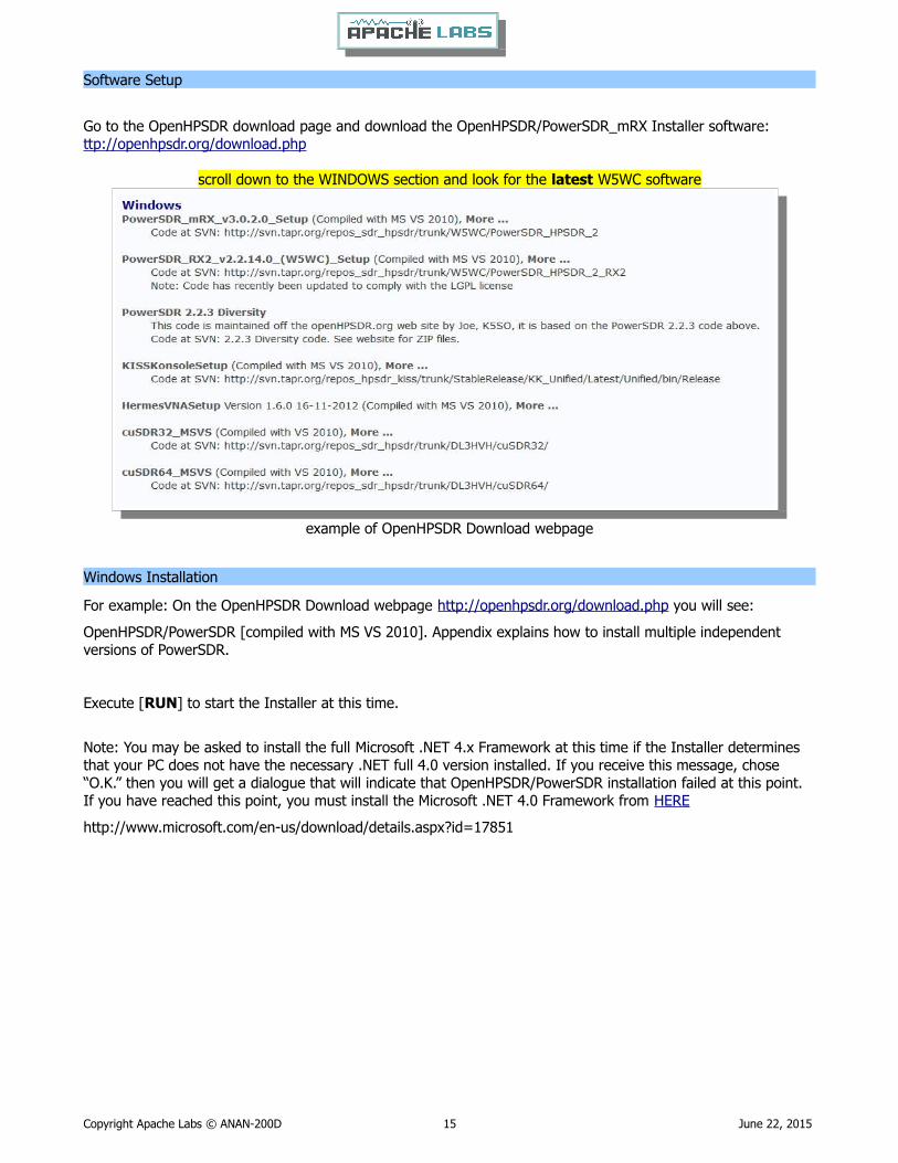
Software Setup
Go to the OpenHPSDR download page and download the OpenHPSDR/PowerSDR_mRX Installer software:ttp://openhpsdr.org/download.php
scroll down to the WINDOWS section and look for the latest W5WC software
example of OpenHPSDR Download webpage
Windows Installation
For example: On the OpenHPSDR Download webpage http://openhpsdr.org/download.php you will see:
OpenHPSDR/PowerSDR [compiled with MS VS 2010]. Appendix explains how to install multiple independent versions of PowerSDR.
Execute [RUN] to start the Installer at this time.
Note: You may be asked to install the full Microsoft .NET 4.x Framework at this time if the Installer determines that your PC does not have the necessary .NET full 4.0 version installed. If you receive this message, chose “O.K.” then you will get a dialogue that will indicate that OpenHPSDR/PowerSDR installation failed at this point. If you have reached this point, you must install the Microsoft .NET 4.0 Framework from HERE
http://www.microsoft.com/en-us/download/details.aspx?id=17851
Copyright Apache Labs © ANAN-200D 15 June 22, 2015
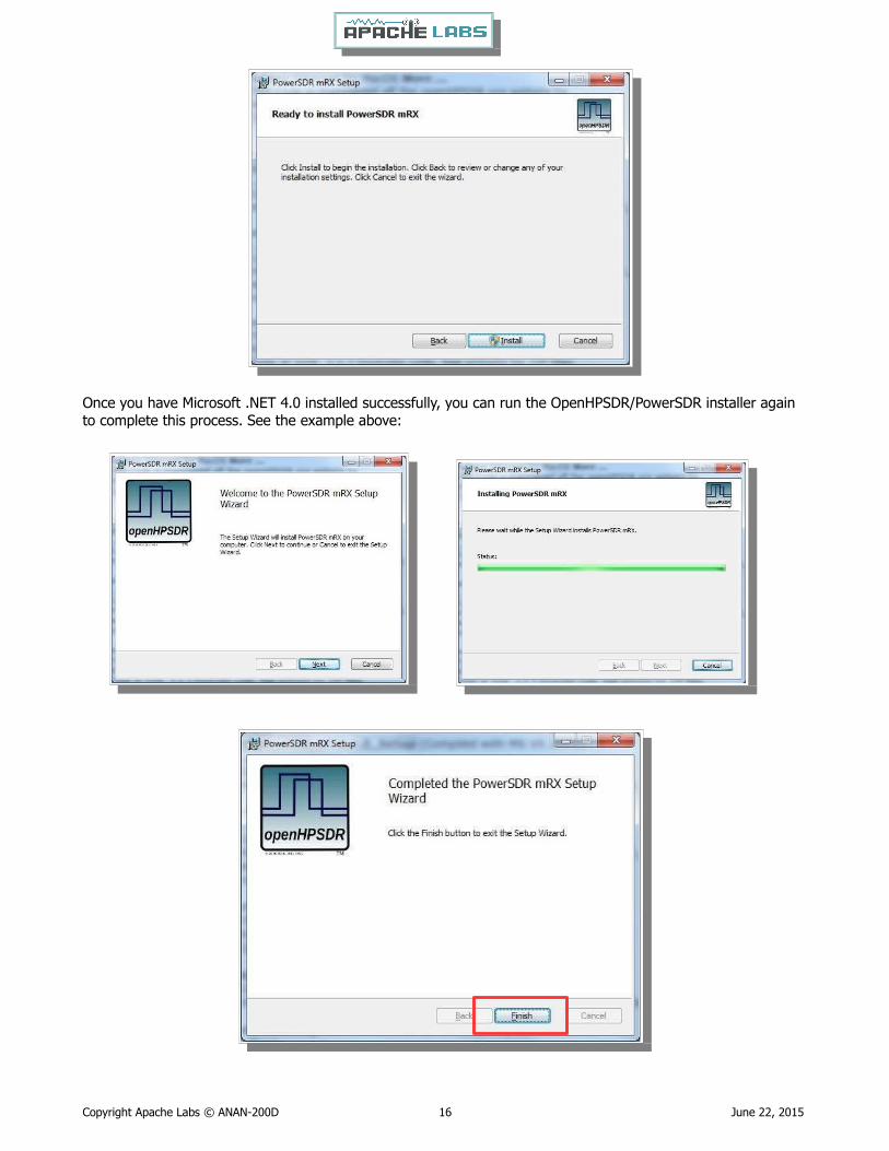
Once you have Microsoft .NET 4.0 installed successfully, you can run the OpenHPSDR/PowerSDR installer again to complete this process. See the example above:
Copyright Apache Labs © ANAN-200D 16 June 22, 2015
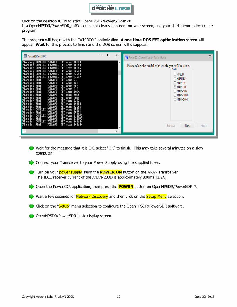
Click on the desktop ICON to start OpenHPSDR/PowerSDR-mRX.If a OpenHPSDR/PowerSDR_mRX icon is not clearly apparent on your screen, use your start menu to locate the program.
The program will begin with the “WISDOM” optimization. A one time DOS FFT optimization screen will appear. Wait for this process to finish and the DOS screen will disappear.
Wait for the message that it is OK. select “OK” to finish. This may take several minutes on a slow computer.
Connect your Transceiver to your Power Supply using the supplied fuses.
Turn on your power supply. Push the POWER ON button on the ANAN Transceiver. The IDLE receiver current of the ANAN-200D is approximately 800ma [1.8A)
Open the PowerSDR application, then press the POWER button on OpenHPSDR/PowerSDR™.
Wait a few seconds for Network Discovery and then click on the Setup Menu selection.
Click on the “Setup” menu selection to configure the OpenHPSDR/PowerSDR software.
OpenHPSDR/PowerSDR basic display screen
Copyright Apache Labs © ANAN-200D 17 June 22, 2015

Note: if you get in trouble with settings and wish to RESET your SYSTEM to it's initial state, look at the bottom of the Setup Menu for the “RESET DATABASE” option. This will over-ride and install a new database with properdefault settings for your ANAN-200D. This can be done at any time. However, it will over-write any special personalization that you might have selected – such as Panadapter color, Display speed in frames per second etc.
Go to → GENERAL → Hardware Configuration tab and note the IP Address and MAC address that are read from the ANAN Transceiver Transceiver.
Note: if the IP ADDRESS is 0.0.0.0 then the software is not communicating with the Transceiveryou must check your LAN connection.OpenHPSDR/PowerSDR/OpenHPSDR software has not been startedPower button on the rig has not been activated
Also check your LAN connector on the ANAN Transceiver to insure that the Link Light on the LEFT side of the LAN connector is illuminated.
Copyright Apache Labs © ANAN-200D 18 June 22, 2015

Make a note of your ANAN Transceiver Transceiver unique MAC address since this will be useful if there is a needfor network problem-solving in the future.
Note: Make sure you have selected the proper radio model from the selections on the LEFT side of the Hardware Configuration box. Failure to do so will result in an improper set of menu options and displays.
The Static IP Addresses are available to point your instance of OpenHPSDR/PowerSDR/OpenHPSDR to a particular Apache Transceiver. There may be several Transceivers on your LAN and the Static IP address is a convenience for pointing this software to a particular unit – where each unit has it's own IP address.
Setup ---> General tab ---> Hardware Config tab, the Radio Model should have ANAN Transceiver selected. Connection Type “ANAN” and “Full Network Discovery” should both be checked. In the “Region, select the Country in which you reside.
The ANAN IP address and Firmware version number in the green box highlighted above will be set automaticallyby your network router DHCP server, or if connected directly to your PC, the IP address will be assigned by the “APIPA” process – WHICH MAY TAKE UP TO SEVERAL MINUTES TO ASSIGN AN IP ADDRESS.
If your LAN is properly configured, the ANAN Transceiver board IP ADDRESS and MAC ADDRESS should be
automatically be detected and assigned. An incorrect default value is 169.254.1XX.XXX.
OpenHPSDR/PowerSDR™ will display the currently assigned IP address and MAC address of the ANAN
Transceiver Hermes board if the LAN connection is properly connected and configured. If the ANAN
Transceiver IP ADDRESS remains 0.0.0.0 then you must determine if OpenHPSDR/PowerSDR and your PC
network connection is operating correctly. Some typical problems could be that the Ethernet connection to
your PC or LAN connector is disabled in Windows. The Ethernet connector may not be properly seated in
your PC or Router. DHCP addressing must be properly enabled on your router. The new HPSDRProgrammer
V2 utility allows you to assign a STATIC IP ADDRESS if you wish.
Please see APIPA appendix of this document for more information.
Copyright Apache Labs © ANAN-200D 19 June 22, 2015
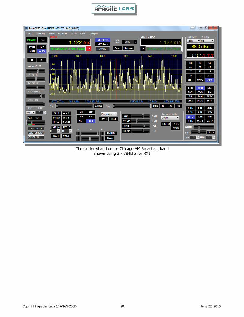
The cluttered and dense Chicago AM Broadcast bandshown using 3 x 384khz for RX1
Copyright Apache Labs © ANAN-200D 20 June 22, 2015

ANAN-200D Antenna ConnectionsThe ANAN-200D provides multiple ways a user can connect antennas and provides great flexibility with numerous options for transmit and receive. Three [3] different Antennas can be connected to the back of the ANAN-200D and be configured to support send or receive on all or a selection of bands by each Antenna. This can be configured on the Ant/Filters tab and additional configuration detail follows later in this manual.
Your ANAN Transceiver assumes a 50 Ohm standard antenna will be connected to Ants 1-3. The ANAN-200D does not have a built in Antenna tuner and therefore unless your antenna’s have a resonant 2:1 SWR, an external tuner should be used to optimized antenna SWR and performance.
The Transceiver provides limited isolation between the Ant 1, Ant 2 and Ant 3 connections by sending the signal to ground and attenuating the receivers input during transmit. Additional attenuation can be selected via the ATT to TX setting on the Ant/Filters tab in PowerSDR MRX Settings.
A very nice feature of the ANAN-200D is it’s ability to monitor your transmit signal on the receivers while transmitting. If you select DUP [DUPLEX] on the main screen in PowerSDR MRX the transmit signal will be visibleon the Panadapter while you transmit allowing you to visually monitor your signal. You must be in Panadapter orPanafall modes to see your signal.
Copyright Apache Labs © ANAN-200D 21 June 22, 2015

Chapter 3 – How to operate SSB PhoneYou need to accomplish the following;
Proper installation of PowerSDR software
Proper installation, power supply, and normal operation of your ANAN-200D Transceiver as indicated in the PowerSDR software windows.
Connecting a suitable Microphone
Most “Computer Condenser” microphones will work when directly plugged into the MIC connector on the front panel of the Apache Transceiver. The Factory settings for Apache Transceivers is to have a small positive voltageapplied to the TIP of the connector for powering a condenser microphone. The RING is connected to push-to-talk, and the SLEEVE is connected to the Transceiver analog ground. The SPACE BAR of your keyboard acts as the default push-to-talk for all microphones. A Computer Condenser mic without a push-to-talk switch can easily be used by substituting the SPACE BAR of your KEYBOARD.
Example: here is a link to a $3 USD microphone using the keyboard space bar for push-to-talk:http://www.officedepot.com/a/products/969486/Cyber-Acoustics-ACM-51-Boom-Microphone/
MIC Adapters
A Ham style, multi-pin microphone requires an adapter. Various adapters are readily available or canbe wired to the Apache 1/8” Stereo style MIC socket.
http://www.ebay.com/itm/like/191566170362?lpid=82&chn=ps
http://www.gigaparts.com/Product-Lines/Microphone-Adapters/Icom-Mic-Adapter-for-Apache-Labs-Transceivers.html
The original ANAN Users Guide has several detailed paragraphs about adapters. The Apache Labs Yahoo Group Files section also has good information about MIC connections and alternatives such as Headsets using a Virtual Audio Cable [VAC] utility or “VB-Audio”.
If you find that you need to change internal jumpers in the ANAN-100, you can refer to the diagram below that is published by Phil Harman VK6PH in his Hermes documentation:
http://svn.tapr.org/repos_sdr_hpsdr/trunk/Hermes/Documentation/Hermes_User_Manual_V1.19
Microphone Connector Databasehttp://www.qsl.net/g4wpw/date.html
If you wish to use a headset, you will need to install a Virtual Audio Cable utility [VAC] or VB-Audio and set it appropriately in the Setup ---> AUDIO ---> VAC1 or VAC2. Please refer to helpful documentation for VAC in the Files section of the Apache Labs Yahoo Group https://groups.yahoo.com/neo/groups/apache-labs/
Copyright Apache Labs © ANAN-200D 22 June 22, 2015
Subject: [apache-labs] PowerSDR_mRX Audio Chain - How it works
From: Warren C. Pratt <[email protected]>
There has been quite a bit of discussion lately of MIC sensitivity and the audio processing in the mRX release. I think a few words of explanation about how things work might be helpful to those exploring various situations and alternatives.
In the case audio enters the MIC connector, it is fairly quickly routed to an audio CODEC to be converted to digital samples. Within that chip, before the ADC, there is a 20dB gain block that can be switched OFF/ON. This gain block is the 20dB Mic Boost that can be selected. Although I haven't tried, I suppose it's possible to overdrive the input stages or
ADC [especially with the 20dB gain block enabled] which could result in clipping of the digital data and resulting distortion.
After conversion to digital, the 16-bit, 48Khz samples are transferred to the computer where they are promptly converted to floating point. With floating point samples, dynamic range is of little consequence as they then progress through the digital signal processing chain. The processing chain is then as follows:
MIC GAIN - a simple multiplier determined by your gain settings is applied to the samples.
DOWNWARD EXPANDER - If activated, the signal is reduced in gain if it is below the threshold set on the console.
GRAPHIC EQUALIZER - If activated, a filter is applied to the audio. The frequency response of the filter is tailored to the response curve that has been set.
LEVELER - If activated, the specified leveler gain is applied to the audio if/when the signal level is running below the leveler's output target amplitude. I currently have the output target set to +0.4 dB. Why not 0 dB? The slight positive bias is beneficial for upcoming features. [Note: NOT the same algorithm that Flex used.]
COMPRESSOR - If activated, the specified maximum compression is applied. Output is compressed to 0dB maximum. [NOTE: Not the compander algorithm that Flex used.]
FILTER - The audio is filtered to match the transmit bandwidth.
ALC - The audio is restricted to 0dB so as not to over-drive the fixed-point dynamic range of the FPGA and/or the DAC. [NOTE: Not the same algorithm used by Flex.]
Finally the audio is converted to 16-bit, 48Khz, samples and transferred to the hardware for up-conversion.
What happens if you run your MIC level above 0dB? If the Leveler is ON, you will get some compression there and everything else runs as normal. If the Leveler is NOT on but the compressor IS, you will get some additionalcompression there, above the value you have selected. If neither the Leveler or Compressor is ON, you will get some compression by the ALC. IN NO EVENT does the compression cause "flat-topping" or "splatter." These phenomena only result from non-linearity and overdrive of the analog amplifiers. Note that the ALC has no knowledge of the analog amplifiers--it is strictly in the digital signal
processing chain.
73,
Warren NR0V
Copyright Apache Labs © ANAN-200D 23 June 22, 2015

Setting up PowerSDR for Phone Operation
With the rig powered on and PowerSDR software running, you should hear great audio from your speakers or headphones connected to the front panel “headphone” jack. Tuning methods are covered on page 38.
Select modulation mode of USB or LSB at the right, center of the OpenHPSDR/PowerSDR window.
Selecting Transmit Profile
The "Profiles" drop down menu allows you select various transmit profiles. The default profile is "Default". You can modify profile settings on this tab and save them to a profile name you select, or you can just modify the included profiles to your liking. You can recall saved profiles at a later time.
Adjusting mic gain
The internal jumpers JP4, JP5, and JP6 on the Hermes board need to be set properly for the type of microphoneused. The default is a simple Condenser mic plugged into the front MIC jack. See the reference section of this document for the jumper settings, or refer to the document by Phil Harman VK6PH: http://svn.tapr.org/repos_sdr_hpsdr/trunk/Hermes/Documentation
You should make all microphone adjustments using a Dummy Load.
Select Setup –-> Transmit the default Source is "Mic In".
Locate the "MIC" gain control slider. It is located at lower right, below the panadapter. The present mic gain setting is shown just to the right of the MIC gain slider.
Copyright Apache Labs © ANAN-200D 24 June 22, 2015
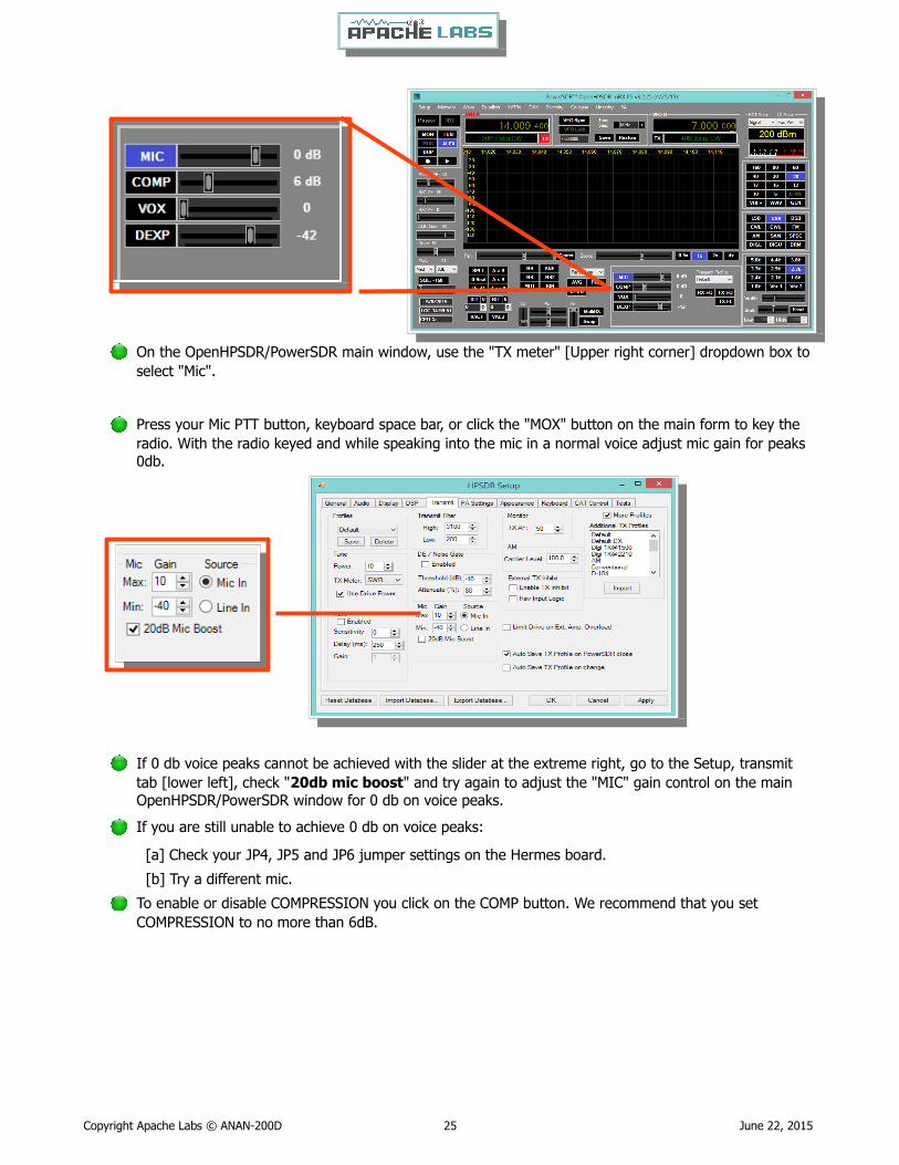
On the OpenHPSDR/PowerSDR main window, use the "TX meter" [Upper right corner] dropdown box to select "Mic".
Press your Mic PTT button, keyboard space bar, or click the "MOX" button on the main form to key the radio. With the radio keyed and while speaking into the mic in a normal voice adjust mic gain for peaks0db.
If 0 db voice peaks cannot be achieved with the slider at the extreme right, go to the Setup, transmit tab [lower left], check "20db mic boost" and try again to adjust the "MIC" gain control on the main OpenHPSDR/PowerSDR window for 0 db on voice peaks.
If you are still unable to achieve 0 db on voice peaks:
[a] Check your JP4, JP5 and JP6 jumper settings on the Hermes board.
[b] Try a different mic.
To enable or disable COMPRESSION you click on the COMP button. We recommend that you set COMPRESSION to no more than 6dB.
Copyright Apache Labs © ANAN-200D 25 June 22, 2015
Transmitting
Tune
The "Tune Power[%]" spinner allows you to select the power output used when the "TUN" button is pressed on the main OpenHPSDR/PowerSDR window. In some versions of OpenHPSDR/PowerSDR, this is actually a percentage of power output rather than output in Watts. The "Tun" button places OpenHPSDR/PowerSDR in CW mode and keys the transmitter using the specified power output level.
The "TX Meter:" drop down selects what the TX Meter on the main form displays when the "Tun" buttonis pressed.
VOX
Click the "enabled" button to enable "Voice Operating Transmit" if you want to cause the transmitter to key when you speak.
Set the sensitivity spinner to a higher value if your wish to have a higher voice level cause the transmitter to key.
Set the delay to cause the VOX to de-key the transmitter after not hearing voice for "Delay [ms]" milliseconds.
Use this with care. Local noises [dog barking, TV playing, door bell, computer sounds] can cause your transmitter to key when you do not want this to happen. Extreme cases can cause your transmitter to key for excessive periods of time resulting in damage to your radio and attached power amplifier.
Transmit Filter
This filter tailors the transmitting frequency response in voice modes.
The default for high is 3100hz in some versions of OpenHPSDR/PowerSDR.
This value exceeds the frequency response allowed on 60 meters in some regions.
You can modify this and other values as needed before hitting the "Save" profile button to save to disk for later recall.
Copyright Apache Labs © ANAN-200D 26 June 22, 2015

HPF/LPF Filters and switching in ANAN Transceiver
The ANAN-200D has a very effective set of High Pass Filters [HPF] and Low Pass Filters [LPF], available on the Setup, General, Ant/Filters/HPF/LPF tab. The HPF and LPF are automatically selected as you change bands, according to the settings on this form.
The ByPass check box on the left side of the HPF/LPF tab, when checked, removes the selected high pass filter from the receive path.
The values in the up/down boxes control the frequency ranges when these filters are automatically selected.
The 6m BPF/LNA bypass check mark controls the 6 meter low noise amplifier and filtering.
The ByPass/55mhz HPF check mark, when enabled bypasses all high pass filters.
The active buttons displayed between the HPF and LPF show which filters are currently active.
The Auto/Manual radio buttons should be left in Auto mode for most operations. Selecting manual will allow you to see what receive filters are selected when you bypass or change receiver frequency ranges etc.
Copyright Apache Labs © ANAN-200D 27 June 22, 2015
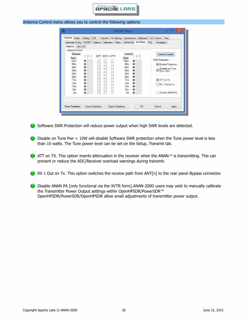
Antenna Control menu allows you to control the following options:
Software SWR Protection will reduce power output when high SWR levels are detected.
Disable on Tune Pwr < 10W will disable Software SWR protection when the Tune power level is less than 10 watts. The Tune power level can be set on the Setup, Transmit tab.
ATT on TX. This option inserts attenuation in the receiver when the ANAN-* is transmitting. This can prevent or reduce the ADC/Receiver overload warnings during transmit.
RX 1 Out on Tx. This option switches the receive path from ANT[n] to the rear panel Bypass connector.
Disable ANAN PA [only functional via the XVTR form].ANAN-200D users may wish to manually calibrate the Transmitter Power Output settings within OpenHPSDR/PowerSDR™ OpenHPSDR/PowerSDR/OpenHPSDR allow small adjustments of transmitter power output.
Copyright Apache Labs © ANAN-200D 28 June 22, 2015

Chapter 4 – How to operate Digital modes
Clarification CCS [30W]/ICAS [100W] operation
AM/FM, CCS [Continuous Commercial Service] 30W
SSB, CW and all ICAS modes [Intermittent Commercial/Amateur Service] 100W PEP
The Power Amplifier MOSFET transistors have characteristics that far exceed the needs of normal Transceiver operation. They are quite rugged. However, other internal components such as the Filters, Integrated Circuits, and some small SMT parts must also be considered when modes with high duty cycles are in use. There are three voltage rails all of which have thermal shutdown protection built in.
Digital modes such as PSK31, RTTY [AFSK), WSPR, JT65A work very well with PowerSDR control software and Apache Transceivers.
Digital operation of a Software Defined Radio may require additional Utilities and supporting software in order tocomplete the complex software [virtual) interconnections for digital operation. Fldigi will be used as an example.
There are dozens of high quality, digital programs available:Helpful catalog of Ham Radio digital software: http://www.dxzone.com/catalog/Software/
Dxzone Software CatalogW1HKJ FldigiVSP, Com0Com, RigCAT, Omni-Rig, VAC, VB-Audio
W1HKJ Fldigi http://www.w1hkj.com/FldigiHelp-3.21/html/index.html
Virtual Audio Cable or VB-AUDIO connections can easily be accomplished with the $25-$40 program called “VAC” or the VB-AUDIO virtual audio cable
VAC is available here http://software.muzychenko.net/eng/vac.htm#downloadVB-Audio is available here: http://vb-audio.pagesperso-orange.fr/Cable/VB-Audio Mixer here: http://vb-audio.pagesperso-orange.fr/Voicemeeter/index.htm
You may also need virtual Serial Ports to interface software PTT connections. Here are two popular Utilities:
http://k5fr.com/ddutilwiki/index.php?title=VSP_Managerhttp://sourceforge.net/projects/com0com/
The Apache Yahoo Group has several helpful digi operating documents:
https://groups.yahoo.com/neo/groups/apache-labs/ files
SignalLink-Hermes-WiringDiagram.pdfhttps://xa.yimg.com/df/apache-labs/PowerSDR-Fldigi_Guide_V2.0.pdf
The KC9XG Yahoo Group also has many helpful diagrams and documents:
https://groups.yahoo.com/neo/groups/KC9XG-SDR/files
Various libraries such as ComCat, RigCat and Omni-Rig may be necessary for CAT [PTT and VFO) control: http://www.dxzone.com/tag-rig-cat-control/ http://www.w1hkj.com/download.html
Copyright Apache Labs © ANAN-200D 29 June 22, 2015
Chapter 5 – How to operate CWSample Rate
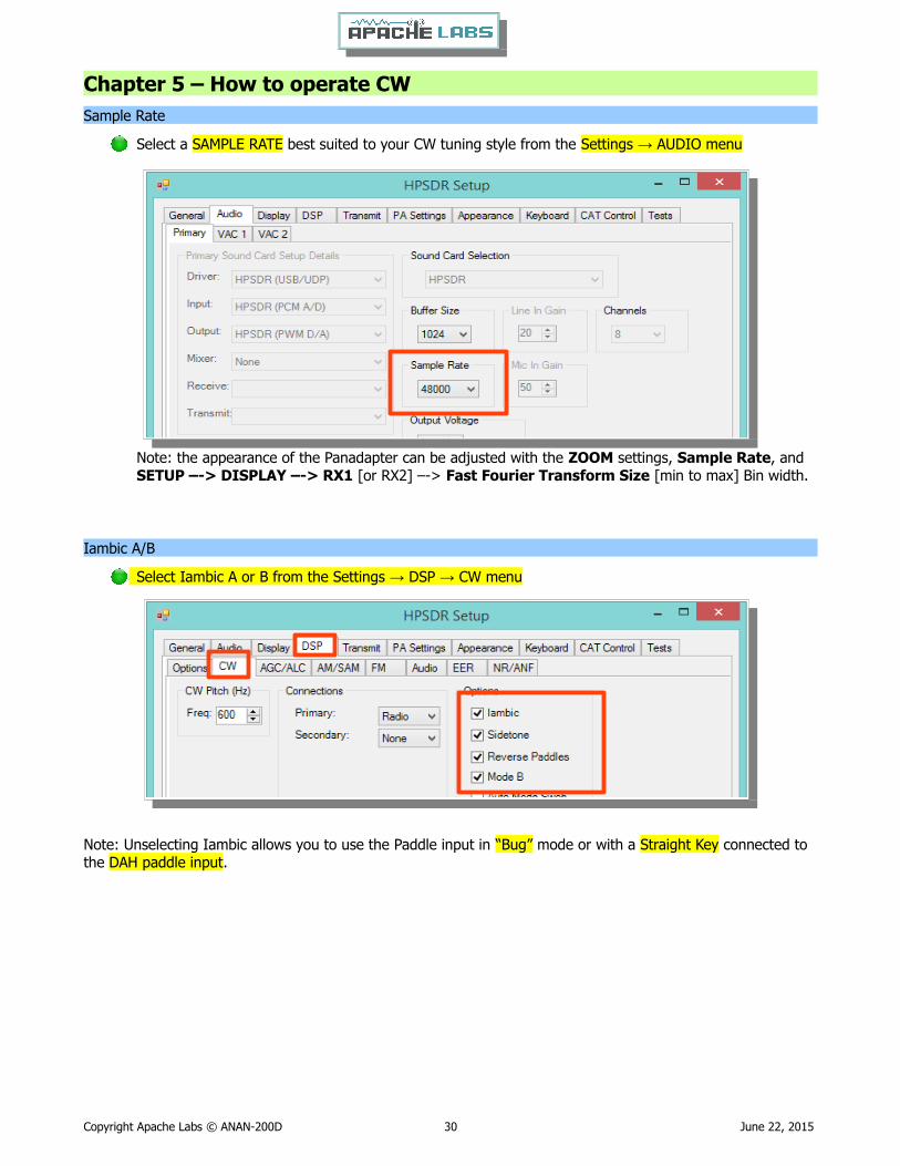
Select a SAMPLE RATE best suited to your CW tuning style from the Settings → AUDIO menu
Note: the appearance of the Panadapter can be adjusted with the ZOOM settings, Sample Rate, and SETUP –-> DISPLAY –-> RX1 [or RX2] –-> Fast Fourier Transform Size [min to max] Bin width.
Iambic A/B
Select Iambic A or B from the Settings → DSP → CW menu
Note: Unselecting Iambic allows you to use the Paddle input in “Bug” mode or with a Straight Key connected to the DAH paddle input.
Copyright Apache Labs © ANAN-200D 30 June 22, 2015

Paddle Connection
Plug your favorite paddles into the front panel using a standard 1/8” Stereo Plug.
To use a CW key with OpenHPSDR/PowerSDR™ you will need to enable it in the menu. To do so, click on Setup → DSP tab followed by the Keyer tab.
Provides connection for a CW key, either straight, single-paddle or Iambic. If using dual-paddle or Iambic mode, the common connection of the key should be made to the sleeve of a 3.5mm 1/8” stereo plug, the “dot” side to the ring and the “dash” side to the tip. If a straight key is used, this should be connected between the sleeve and the tip of the plug. PowerSDR Software enables the dot and dash connections to be reversed via a menu selection [above]. The dot and dash connections are connected to a 3.3vdc via a 1k resistor.
If you find that your DAH and DIT paddles are reversed, there is a very convenient SETUP check box to put DAH on tip and DIT on Ring of the input PLUG
CWU/CWL
Select CWLower or CWUpper from the MODE buttons in the main window. Note the position of the filter changes in the main window.
Copyright Apache Labs © ANAN-200D 31 June 22, 2015
0

Select Operating Frequency
Using your mouse on the PANADAPTER display, select your operating frequency.
Note that you can see your CW [BFO] CENTER FREQUENCY or TX FREQUENCY by checking the boxes on the main screen. Those convenient vertical yellow marker-lines are really great when you are working split. The SPEED of the internal Iambic Keyer is shown at the top of this picture.
Set Drive Level
Set the DRIVE LEVEL slider to 50% [mid range].
Copyright Apache Labs © ANAN-200D 32 June 22, 2015
Break-in Delay
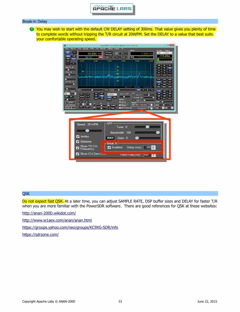
You may wish to start with the default CW DELAY setting of 300ms. That value gives you plenty of time to complete words without tripping the T/R circuit at 20WPM. Set the DELAY to a value that best suits your comfortable operating speed.
QSK
Do not expect fast QSK. At a later time, you can adjust SAMPLE RATE, DSP buffer sizes and DELAY for faster T/Rwhen you are more familiar with the PowerSDR software. There are good references for QSK at these websites:
http://anan-200D.wikidot.com/
http://www.w1aex.com/anan/anan.html
https://groups.yahoo.com/neo/groups/KC9XG-SDR/info
https://sdrzone.com/
Copyright Apache Labs © ANAN-200D 33 June 22, 2015
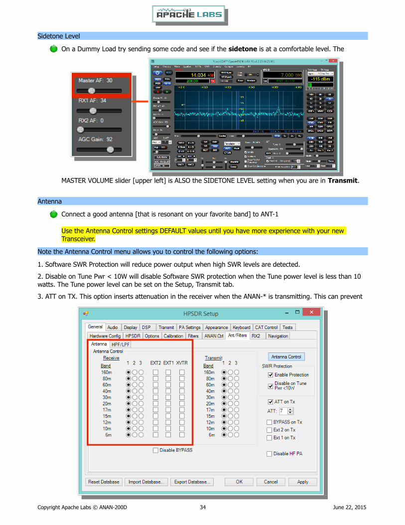
Sidetone Level
On a Dummy Load try sending some code and see if the sidetone is at a comfortable level. The
MASTER VOLUME slider [upper left] is ALSO the SIDETONE LEVEL setting when you are in Transmit.
Antenna
Connect a good antenna [that is resonant on your favorite band] to ANT-1
Use the Antenna Control settings DEFAULT values until you have more experience with your new Transceiver.
Note the Antenna Control menu allows you to control the following options:
1. Software SWR Protection will reduce power output when high SWR levels are detected.
2. Disable on Tune Pwr < 10W will disable Software SWR protection when the Tune power level is less than 10 watts. The Tune power level can be set on the Setup, Transmit tab.
3. ATT on TX. This option inserts attenuation in the receiver when the ANAN-* is transmitting. This can prevent
Copyright Apache Labs © ANAN-200D 34 June 22, 2015

or reduce the ADC/Receiver overload warnings during transmit.
4. RX 1 Out on Tx. This option switches the receive path from ANT[n] to the rear panel Bypass connector.
5. Disable ANAN PA [only functional via the XVTR form]
Tuning
Methods for tuning your Transceiver to a frequency
The ANAN-200D ADC samples the entire spectrum from 10khz through approximately 61.44 Mhz. The receivers are implemented in the FPGA where their data is decimated to an amount of spectrum suitable to send over Ethernet to your PC. If you have an antenna that will receive all those frequencies [like a vertical, loop, or dipole) you can tune your Rx1 and Rx2 to independent bandwidths [selected by the Sample Rate) and frequencies at the same time.
Rx1 might be on your Left speakers [or headphones) and Rx2 might be on the right speaker with easy front panel PowerSDR controls. MultiRx feature a second receiver within the passband of the primary receiver. Rx2 will be undisturbed by the MultiRx and will continue to receive it's independent band and frequency. Take note of the Multi and Rx2 controls in the main Window of PowerSDR.
Direct numeric input
Keyboard commands – see Setup → Keyboard menu
Point and Click with MouseThe mouse can be used to tune signals on the Waterfall or Panadapter. Select an active amateur band by clicking on one of the band buttons located just below the "S Meter" in the upper right portion of the OpenHPSDR/PowerSDR window.
If you right click the mouse on the Panadapter you can go into "click tune" mode. The display will show a yellowindicator tuning line and filter width setting. Left clicking with the mouse will then QSY the receiver to that frequency. You can right click again to revert from "click tune" mode to "drag" tuning mode.
The "Zoom" slider and the "0.5x, 1x, 2x and 4x" buttons can be used to modify the frequency range displayed inthe Panadapter. These controls are located just below the Panadapter/waterfall display. The "Pan" button can be used to move the displayed frequencies within the selected range.
Copyright Apache Labs © ANAN-200D 35 June 22, 2015
Drag MouseIf you press and hold the left mouse button you can "drag" the frequency of interest into the panadapter highlighted filter area.
Roll Mouse Wheel – see main window TUNE STEP selections
CTUNE
The PowerSDR "CTUN" button enables "Click Tuning" while using the panadapter and waterfall displays. "Click tuning" when active, allows you to click within the Panadapter or waterfall to QSY without shifting the Panadapter or Waterfall display. When "CTUN" is inactive, clicking on the Panadapter re-centers the panadapter, thereby shifting the entire panadapter. Note that the " CTUN" function only works within a frequency range equal to the sample rate. IOW, if the selected sample rate is 384khz and RX1 panadapter is 1 MHz, wide, CTUN will only function within the center 384khz of the panadapter or waterfall display.
DUP
The PowerSDR "DUP" [DUPLEX] button enables RX1 reception during transmit, allowing the user to view the transmitted RF signal in the Panadapter. The ANAN-200D transceivers switch the selected antenna [ANT1, ANT2,or ANT3] to ground during transmit, thereby protecting the receiver from damage due to high RF levels. Monitoring of the RF transmission using the "DUP" feature is visible in the Panadapter and Panafall modes.
LOCK VFO – prevents an unintended change of VFO frequency while in a QSO
Copyright Apache Labs © ANAN-200D 36 June 22, 2015
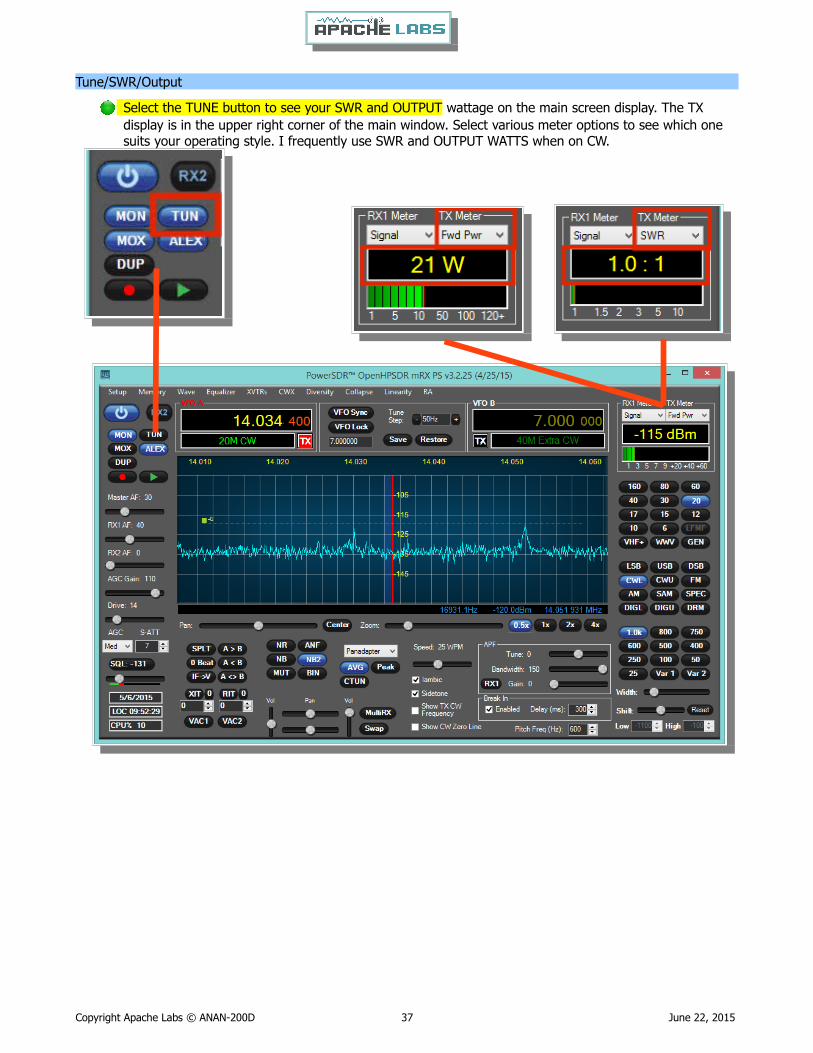
Tune/SWR/Output
Select the TUNE button to see your SWR and OUTPUT wattage on the main screen display. The TX display is in the upper right corner of the main window. Select various meter options to see which one suits your operating style. I frequently use SWR and OUTPUT WATTS when on CW.
Copyright Apache Labs © ANAN-200D 37 June 22, 2015

Drive Level
If you have not yet completed a MANUAL PA CALIBRATION, then the output may be a bit above or below your desired DRIVE slider setting. The PowerSDR default PA CALIBRATION values are usually very good for most Apache Transceivers. Note: the Drive Level is a percentage and not the numerical watts output.
Enjoy your first QSO and be sure to share the news with all the Hams on the Apache Yahoo Group.
https://groups.yahoo.com/neo/groups/apache-labs/info
Copyright Apache Labs © ANAN-200D 38 June 22, 2015
Chapter 6 – How to Interface to your Linear AmplifierPTT Input
PTT Output
Most modern Linear Amplifiers have a connection for PTT input for keying the Linear. Apache Transceivers include a back panel connection for this purpose and it is activated by the PowerSDR software based on menu preferences. On the ANAN-200D Linear Amplifier PTT OUT it is pin 1 of the AUX I/O Ribbon connector.
FET
The PTT OUT is a common DRAIN 2n7002 type FET transistor as shown in the schematic for the ANAN-200D.
The heavy duty type FET is best used to switch 25vdc and 800ma [or less). Exceeding these values may damage the PTT OUTPUT circuit.
How to test your PTT Linear Amplifier circuit BEFORE connecting your Apache Transceiver.
Power your Linear, connect the control cable to your linear but do not connect the other end to your Apache Transceiver
Using a DC Voltmeter, measure the voltage between the center pin and the outer connection of the cable. This must be less than 25vdc.
Connect a DC Ammeter between the center pin and the exciter connection of the cable. This should ACTIVATE the Linear Amplifier and give you a clear measurement of the current requirements. The ANAN-200D PTT circuit should not draw more than 800ma.
If either of these values are out of the required range, then use an external keying interface. There are many keying interfaces available from many sources such as MFJ, Elecraft, DX Engineering.
Important: Connecting a Linear Amplifier that does not meet the above voltage and current requirements is likely to cause damage to the Apache Transceiver linear switching transistor and extreme cases, serious damage to other parts. Damage to the radio caused in this manner is not covered by Warranty.
Various Linear Amplifier Keying ISOLATION adapters are available
http://www.dxengineering.com/search/product-line/kd9sv-products-sv-kr-keying-relays
http://www.ameritron.com/Product.php?productid=ARB-704
http://www.sultantronics.com/product.html
http://stores.ebay.com/radiodan-w7rf?_trksid=p2047675.l2563
ALC
K2UE has written a helpful document about how he uses ALC with his Apache Transceiver. You can find it in the Apache Yahoo Group FILES section: https://xa.yimg.com/df/apache-labs/ExtALC+Installation+%26+Use.pdf
For more information about suitable couplers from the KC9XG Yahoo Group Files section:https://xa.yimg.com/df/KC9XG-SDR/PSSamplersCouplers.pdf
Copyright Apache Labs © ANAN-200D 39 June 22, 2015
Various directional coupler models are available
http://www.elecraft.com
http://www.wavenode.com
http://www.cleanrf.com
In practice, the ANAN-200D works well with PureSignal with no external RF Sampler when running 10W. You will need to determine the suitability of your Linear Amplifier to the modes you wish to operate.
Automatic Band Selection can be accomplished using the Open Collector Output transistors available on the AUXI/O Connector on the back panel. DDUTIL?
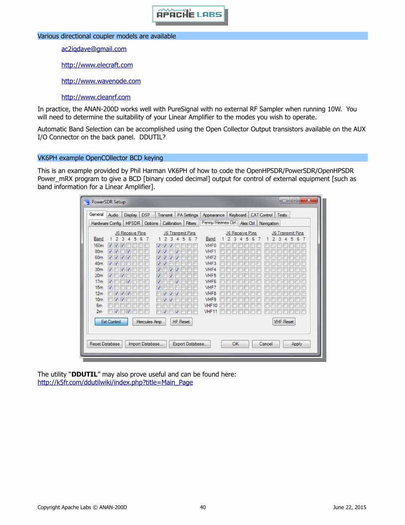
VK6PH example OpenCOllector BCD keying
This is an example provided by Phil Harman VK6PH of how to code the OpenHPSDR/PowerSDR/OpenHPSDR Power_mRX program to give a BCD [binary coded decimal] output for control of external equipment [such as band information for a Linear Amplifier].
The utility “DDUTIL” may also prove useful and can be found here: http://k5fr.com/ddutilwiki/index.php?title=Main_Page
Copyright Apache Labs © ANAN-200D 40 June 22, 2015
Chapter 7 – How to use PureSignal Adaptive predistortion
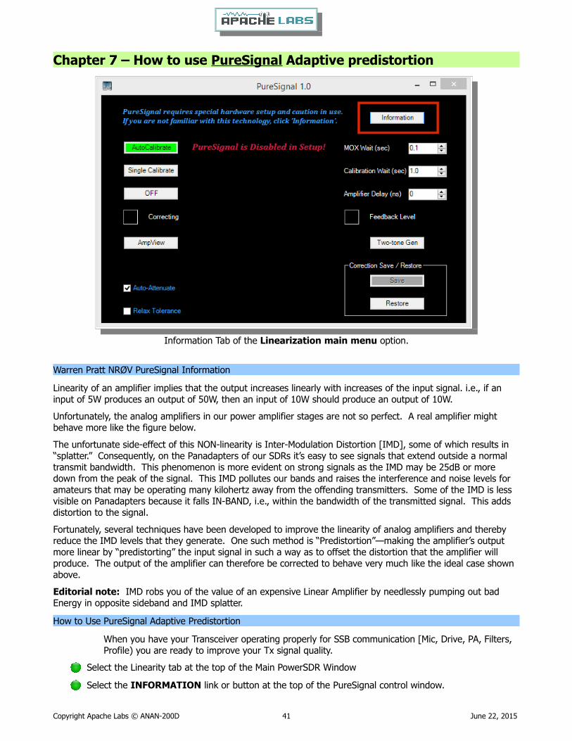
Information Tab of the Linearization main menu option.
Warren Pratt NRØV PureSignal Information
Linearity of an amplifier implies that the output increases linearly with increases of the input signal. i.e., if an input of 5W produces an output of 50W, then an input of 10W should produce an output of 10W.
Unfortunately, the analog amplifiers in our power amplifier stages are not so perfect. A real amplifier might behave more like the figure below.
The unfortunate side-effect of this NON-linearity is Inter-Modulation Distortion [IMD], some of which results in “splatter.” Consequently, on the Panadapters of our SDRs it’s easy to see signals that extend outside a normal transmit bandwidth. This phenomenon is more evident on strong signals as the IMD may be 25dB or more down from the peak of the signal. This IMD pollutes our bands and raises the interference and noise levels for amateurs that may be operating many kilohertz away from the offending transmitters. Some of the IMD is less visible on Panadapters because it falls IN-BAND, i.e., within the bandwidth of the transmitted signal. This adds distortion to the signal.
Fortunately, several techniques have been developed to improve the linearity of analog amplifiers and thereby reduce the IMD levels that they generate. One such method is “Predistortion”—making the amplifier’s output more linear by “predistorting” the input signal in such a way as to offset the distortion that the amplifier will produce. The output of the amplifier can therefore be corrected to behave very much like the ideal case shown above.
Editorial note: IMD robs you of the value of an expensive Linear Amplifier by needlessly pumping out bad Energy in opposite sideband and IMD splatter.
How to Use PureSignal Adaptive Predistortion
When you have your Transceiver operating properly for SSB communication [Mic, Drive, PA, Filters, Profile) you are ready to improve your Tx signal quality.
Select the Linearity tab at the top of the Main PowerSDR Window
Select the INFORMATION link or button at the top of the PureSignal control window.
Copyright Apache Labs © ANAN-200D 41 June 22, 2015
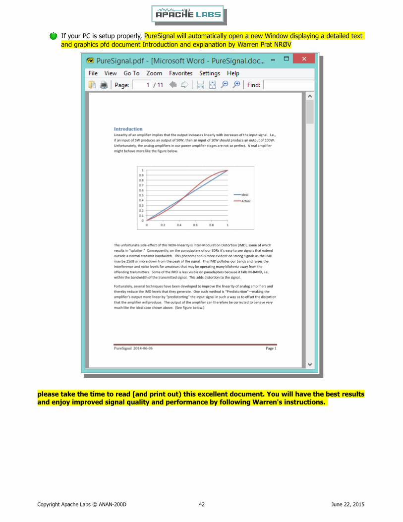
If your PC is setup properly, PureSignal will automatically open a new Window displaying a detailed text and graphics pfd document Introduction and explanation by Warren Prat NRØV
please take the time to read [and print out) this excellent document. You will have the best resultsand enjoy improved signal quality and performance by following Warren's instructions.
Copyright Apache Labs © ANAN-200D 42 June 22, 2015

In PowerSDR release 3.2.25 Warren has introduced a sophisticated new “Automatic Tx Attenuation” adjustment.
This was previously done manually by the operator using Setup ---> General ---> Ant/Filt and adjusting the thumb wheel value of ATT on TX [as shown below) while watching for a GREEN Feedback Level in the Linearization window indicating that you have sufficient feedback RF signal for PureSignal to measure, evaluate, and correct with Adaptive Distortion techniques in the DAC Tx signal.
With the new automatic adjustment feature, Warren has dramatically improved PureSignal so that it is now even easier to use on a routine basis.
Using a DUMMY LOAD and your Panadapter set for DUP, you can activate the TWO TONE button in the PureSignal Window. You should immediately see your transmitted signal displayed with the primary and odd harmonic peaks. PureSignal will adjust your ATT on Tx for an optimal value and then in just a few seconds it willlower your 3rd ,5th ,7th harmonic peaks to a surprisingly lower level. PureSignal can optimally adjust unwanted IMD by as much as -45dbc. PureSignal will continue to optimize your signal as you speak in a normal voice.
Users who have a Linear Amplifiers properly equipped with an RF Signal Sampler will see a similar improvement in the quality of their transmitted two tone signal to the extent that PowerSDR can make mathematical adjustments for distortion introduced by the Linear Amplifier.
For more information about suitable couplers from the KC9XG Yahoo Group Files section:https://xa.yimg.com/df/KC9XG-SDR/PSSamplersCouplers.pdf
Various directional coupler models are available
[email protected]://www.elecraft.comhttp://www.wavenode.comhttp://www.cleanrf.com
Copyright Apache Labs © ANAN-200D 43 June 22, 2015

Chapter 8 – How to install a new version of PowerSDR softwarePlease refer to the Quick Start Software Installation information in Chapter 2
The most convenient method for updating is to download and install the latest PowerSDR .msi installation file from the OpenHPSDR Download webpage.
Updates to the PowerSDR software are issued by the volunteer Development Team on the OpenHPSDR Download webpage: http://openhpsdr.org/download.php
There have been a series of updates to add many new features and to improve performance. The current program is compiled with Microsoft® Visual Studio VS2010 and may be updated to VS2013 in the future. PowerSDR is written in “C” and “C#”. The program is OpenSource.
Announcements about the latest version of PowerSDR are made via email on the Apache Labs Yahoo Group and the OpenHPSDR email list.
If you would like to test the latest update, you may wish to follow this safe procedure:
BACKUP your current installation on a USB Flash Drive or DVD/CDROM so that you can restore your current operational preferences and settings in the even that you do not with to continue with the latest version of PowerSDR.
Instructions to load independent versions on a single PC are summarized here:
Go to the Properties of the shortcut.
At the end of the Target you can add the new directory path using the command line argument –datapath:<”directory path”>
To create a new directory for the ANAN-200D radio I use the name PowerSDR ANAN_10 like this:
start --datapath:"%appdata%\FlexRadio Systems\PowerSDR ANAN_10\"
My new Target will look like this:
"C:\Program Files [x86]\OpenHPSDR\PowerSDR RX2 [W5WC]\PowerSDR.exe"
--datapath:"%appdata%\FlexRadio Systems\PowerSDR mRX\"
When you start PowerSDR using the modified shortcut you will receivethis message the first time.
Ensure the directory path is correct. The click on Yes.
You will then get the normal startup with a new wisdom file and database created in the new folder.
Each installation of PowerSDR makes entries in BOTH the %appdata% and Program Files (x86) folders.If you install a new version, it will override the XML DataBase that contains the detailed description of allyour settings and preferences.
at this time, there is no utility to retain your preferences and apply them to the next revision database
Copyright Apache Labs © ANAN-200D 44 June 22, 2015

Chapter 9 - How/when to install a new version of Apache FirmwareNew Firmware upgrades for all Apache Transceivers will be posted on the Apache Web site following acceptance testing by the Apache technical staff: http://www.apache-labs.co
HPSDRBootloader
The ANAN-10, ANAN-100 use a Hermes Transceiver board and firmware.
The ANAN-100D uses the ANGELIA Transceiver board and firmware.
The ANAN-200D uses the ORION Transceiver board and firmware.
The ANAN-200D Transceivers were designed with an EEPROM to store the “bootloader” code in lower memory and the FPGA firmware .rbf file in upper memory [as shown below). It is usually not necessary to reload the bootloader code.
Firmware updates are most easily uploaded into the EEPROM storage memory using the KVØS HPSDRProgrammer or HPSDRBootloader utilities. The most recent revision of these utilities is available on the OpenHPSDR Download webpage: http://openhpsdr.org/download.php
Firmware for the ANAN-200D is issued infrequently. Apache Labs installs the latest Firmware in each Transceiver at the Factory. The Firmware is stable and will operate smoothly without any maintenance required.
However, in the event that there is an update to add new features or improve performance, you should familiarize yourself with the documentation prepared by Phil VK6PH:
http://svn.tapr.org/repos_sdr_hpsdr/trunk/Hermes/Documentation/Hermes_User_Manual_V1.18.pdf
EEPROM
Should you need any help with a firmware upgrade for your ANAN-200D, please contact Apache Labs Support <[email protected]>
Please do not attempt the Firmware upgrade if you are unsure about the reason for the update and the benefit to your ANAN-200D.
Copyright Apache Labs © ANAN-200D 45 June 22, 2015
.rbf code for FPGA
.pof bootloader code
1MB
HPSDRBootloader loads “.pof” code into the first
1MB of EEPROM
HPSDRProgrammerLoads FPGA code into
the second Megabyte of EEPROM

Pointers to reference materials
Apache Labs International Support
Technical support for ANAN-200D from the factory is available via the Apache Labs Yahoo Group http://groups.yahoo.com/group/apache-labs/
or directly via email <[email protected]>
Apache Yahoo Support Group
http://groups.yahoo.com/group/apache-labs/
OpenHPSDR Group
Instructions relating to joining the OpenHPSDR Group reflector are here:
http://lists.openhpsdr.org/listinfo.cgi/hpsdr-openhpsdr.org
The OpenHPSDR archives may also be searched here:
http://lists.openhpsdr.org/mmsearch.cgi/hpsdr-openhpsdr.org
The latest version of the OpenHPSDR User Manual can be obtained from
http://openhpsdr.org/documents.php Revision 1.9 Author Phil Harman VK6PH
Apache Service and Repair
1023 Tower B4, Spaze I-Tech Park
Sector - 49, Sohna Road
Gurgaon - 122001
Haryana, India
Tel: 91-0124-4245173/4/5 [10AM - 6PM IST]
Email: [email protected]
Website: http://www.apache-labs.com
Apache Schematics
The current Apache ANAN-200D schematic may be downloaded from:
https://apache-labs.com/al-downloads/1002/Hermes-Design-Files.html
Copyright Apache Labs © ANAN-200D 46 June 22, 2015

Original 2013 Users Guide
Please refer to the Technical Reference document [formerly User Guide v3.4] for information about various microphones and how to adapt them to the Apache Transceiver. You may find this reference helpful:
Website: http://www.apache-labs.com
Balanced Audio Input is not implemented in the current Apache Labs Transceivers.
The LEFT LINE level input is currently selectable in PowerSDR as an alternative to the mic input.Balanced audio is not supported by the Audio ADC hardware used in the ANAN radios. If a balanced input is required then an external balanced to unbalanced transformer [or active electronic equivalent] will be required.
Multiple independent .xml databases
Thank you Doug W5WC for this important information.Go to the Properties of the shortcut.
At the end of the Target you can add the new directory path using thecommand line argument –datapath:<”directory path”>
To create a new directory for the ANAN-200D radio I use the name PowerSDRANAN_10 like this:
start -datapath:"%appdata%\FlexRadio Systems\PowerSDR ANAN_10\"
My new Target will look like this:
"C:\Program Files [x86]\OpenHPSDR\PowerSDR RX2 [W5WC]\PowerSDR.exe"-datapath:"%appdata%\FlexRadio Systems\PowerSDR mRX\"
When you start PowerSDR using the modified shortcut you will receivethis message the first time.
Ensure the directory path is correct. The click on Yes.
You will then get the normal startup with a new wisdom file and databasecreated in the new folder.
Copyright Apache Labs © ANAN-200D 47 June 22, 2015

Manual Calibration Procedure
Use the following manual calibration procedure to properly set/calibrate your ANAN-200D power output into a dummy load:
1. Connect a suitable Dummy Load to ANT1 BNC port on the back panel of the Transceiver.
2. Click on menu selection, Setup, Transmit.
3. Set “TUNE”, Power % to 100
4. Select “FWD Pwr” from the “TX Meter” upper right corner of the main OpenHPSDR/PowerSDR/OpenHPSDR window.
5. Enable the Antenna window by clicking on Setup ---> General ---> ANT/FILTERS tab to access the antenna settings.
6. Select the Transmit antenna ANT1 where you connected the Dummy Load.
7. Select the PA settings TAB on the Setup menu window.
The PA Settings TAB allows you to set [calibrate] the ANAN-200D Power Amplifier gain by band [dB – Power Output per Band] for each of the available Ham Bands. There is an up/down gain control for each band, which regulates the Power Amplifier output for that band. As you increase the Gain By Band, power output will decrease. Conversely, decreasing Gain By Band will increase Power Amplifier output.
Maximum power output per band can be reached at the lowest value in this menu.
8. Select one of the bands on the PA settings TAB.
Copyright Apache Labs © ANAN-200D 48 June 22, 2015

9. Ensure you have the Setup ---> Transmit tab ---> Tune control set to 10 and a Dummy Load connected to the selected antenna port on the ANT/FILTERS setup tab.
10. Press “TUN” [Tune] on the upper left side of the OpenHPSDR/PowerSDRmain display form on your computer.
11. Adjust the band gain value for a MAXIMUM TX Meter “FWD PWR” outputreading of 10 watts while using your suitable Dummy Load. Do NOT use anAntenna for this calibration adjustment.
12. Press “TUN” button again to unkey the radio.
Repeat the above procedure for each Ham Band to properly calibrate the RF CWpower output for a MAXIMUM 10 watts.
13. When all bands have been calibrated, remove the Dummy Load and selectthe antenna of your choice in the ANT/FILTERS setup Tab.
14. Remember to reduce the “TUN” power wattage setting on the Setup ---> Transmit tab to approximately 9W.
Computer Performance
Processing of streaming data in real-time can be a challenging task for Windows-based applications and device drivers. This is because by design Windows is not a real-time operating system. There is no guarantee that taskscan be executed in a deterministic [timely] manner.
Audio or video data streams transferred from or to an external device are typically handled by a kernel-mode device driver. Data processing in such device drivers is interrupt-driven.
Typically, the external hardware periodically issues interrupts to request the driver to transfer the next block of data. In Windows NT-based systems [Windows 2000 and later] there is a specific interrupt handling mechanism.When a device driver cannot process data immediately in its interrupt routine, it schedules a Deferred ProcedureCall [DPC]. Microsoft defines them as: A Deferred Procedure Call [DPC] is a queued call to a kernel mode function that will usually be executed at a later time. DPCs are used by drivers to schedule I/O operations that do not have to take place in an ISR at a high IRQL, and can instead be safely postponed until the processor IRQL has been lowered. When you look at Windows Task Manager and sort the running processes by CPU [Processor Utilization], the System Idle Process is almost always at the top of the list. What you may not know isthat ‘process’ is really a roll-up of several things. Among other things included in that CPU number, is hardware interrupts and DPCs. You can see these two items by using the Microsoft “SysInternals” Process Explorer available here: Process Explorer
The Sycon's DPC Latency Checker is a free Windows tool that analyzes the capabilities of a computer system to handle real-time data streams properly. It may help you to determine if your personal computer is capable of powering your HPSDR system or to find the cause for interruptions in real-time audio and video streams, also known as ‘drop-outs’. The program supports Windows 2000, Windows XP, Windows XP x64, Windows Server 2003, Windows Server 2003 x64, Windows Vista, Windows Vista x64, Windows 7 32 bit and 64 bit and is available here. Latency checker found by N9VV
http://www.resplendence.com/latencymonandhttp://www.thesycon.de/deu/latency_check.shtml
Copyright Apache Labs © ANAN-200D 49 June 22, 2015
Warranty
We warrant that our products are free of defects in material and workmanship and extend this warranty under intended use and normal service conditions to the original owner for a period of one year from the date of purchase. This warranty does not apply to any product that has been repaired [Unauthorized] or altered in any manner and is void if damaged by accident, neglect, unreasonable use, improper installation, lack of proper impedance matching [High SWR], improper tuning, over driving power limits, damage due to use of any third party accessories, or any other cause not arising specifically out of defects in material or workmanship.
Our obligations are limited to repairing or replacing, at our sole discretion, any product or part that is returned to the mailing address, all shipping or transportation charges must be pre-paid, accompanied by proof of purchase and which examination reveals to have been defective within the warranty period stated above.
Our Warranty does not imply any obligation other than herein stated. Any implied warranties, including but not limited to fitness for a particular purpose, are limited in duration for the above one year period.
We shall not be liable under this warranty, or any implied warranty, for loss of use of the product or for any other consequential loss or damage incurred by the purchaser.
Warranty -- Apache Labs website has a link to explain their warranty and other pertinent information:http://www.apache-labs.com/terms-of-use.html under "Terms of Use".
IMPORTANT
The FPGA and other components on the ANAN-200D PCBs can be damaged by Electrostatic Discharge [ESD]. When handling the PCB, you should take ESD precautions [e.g. use a work bench with an antistatic mat on it and wear a grounded wrist strap].
When powered on do not touch the top of any IC in order to determine its temperature. In particular, do not touch the Switch Mode Regulator IC. Touching its leads can change the switching frequency and alter the outputvoltage.
Copyright Apache Labs © ANAN-200D 50 June 22, 2015
OpenHPSDR Software
OpenHPSDR/PowerSDR modificationsW5WC source code: click here
http://svn.tapr.org/repos_sdr_hpsdr/trunk/W5WC
W5WC skins with installer herehttp://svn.tapr.org/repos_sdr_hpsdr/trunk/W5WC/OpenHPSDR_Skins/
K.I.S.S_Konsole from OpenHPSDR team http://svn.tapr.org/repos_hpsdr_kiss/branches/K9TRV/KISSKonsoleUnified
VK6PH has added new VNA capabilities to FPGA and K.I.S.S. codes.
ghpsdr3 - QtRadio from John Melton GØORX/N6LYT and a new branch by Alex Lee
Heterodyne [MAC/OS] by Jeremy McDermond
OpenHPSDR software repository and informationhttp://openhpsdr.org/download.php
Copyright Apache Labs © ANAN-200D 51 June 22, 2015
Contributing members to the Hermes project
THANK YOU each for the wonderful gift you have shared with us all
Kevin Wheatley M0KHZ who conceived the Hermes and is the Project Lead
Abhi Arunoday Managing Director, Apache Labs, PCB layout, manufacturer
Phil Harman - VK6PH - Software & hardware development, especially the brain wave for maintaining full DAC bits while reducing power.
Bill Tracey - KD5TFD - Component sourcing and kitting
Lyle Johnson - KK7P - significant contributor to hardware development
Scotty Cowling - WA2DFI – Parts procurement
Graham - KE9H - Hermes PA improvements
Doug W5WC for his adaptation of FLEX OpenHPSDR/PowerSDR to Hermes
Joe K5SO for his many software contributions.
George Brykit K9TRV for his installer and other software contributions.
Plus numerous other contributors via the OpenHPSDR reflector.
Apollo, a companion 20W PA, LPF and ATU, was conceived by Kjell Karlsen – LA2NI
Copyright Apache Labs © ANAN-200D 52 June 22, 2015

The CORDIC Algorithm
The CORDIC mathematical algorithm used in the Apache-10W Transceiver;
CORDIC - Wikipedia, the free encyclopediahttp://en.wikipedia.org/wiki/CORDIC
CORDIC FAQhttp://www.dspguru.com/dsp/faqs/cordic
CORDIC FAQ-IIhttp://www.dspguru.com/info/faqs/cordic2.htm
CORDIC for Dummieshttp://www.jacques-laporte.org/cordic_for_dummies.htm
The CORDIC Algorithmhttp://www.andraka.com/cordic.htm
CORDIChttp://www.nist.gov/dads/HTML/cordic.html
From Hermes VHDL designer Phil Harman VK6PH:
The CORDIC takes the input samples and multiplies them by the sine and cosine of the phase value we feed to it [i.e. the frequency we want to tune to]. The CORDIC is a successive approximation approach to generating the sine and cosine of an angle - since it only uses add and shift logic it was used in the early hand-held calculators. If we use enough bits in the CORDIC then the sine and cosine values it generates are so accurate that we get perfect I & Q signals out in terms of how well the amplitudes are matched and how close to 90 degrees apart they are.
As I said it is a successive approximation approach so it takes about 20 iterations to get the accuracy weneed. In which case there is a delay of 20/122.88MHz from the time the RF appears at its input to the time the Iand Q signals appear.
Because of this delay we use a technique called pipelining - we feed samples into a pipe that is 20 samples long and at the end of the pipe take the result out.
We decimate and filter at the same time. The CIC is a very simple way to produce a filter [just adds andsubtracts] so it is very efficient to implement in the FPGA. But it's frequency response is not ideal so we follow it with a CFIR that compensates for the droop in the CIC passband and cleans up the overall shape.
The Hermes FPGA Verilog code can be found on the SVN http://openhpsdr.org/download.php
Copyright Apache Labs © ANAN-200D 53 June 22, 2015

ANAN-200D Accessory Port [back panel]
The Hermes/Angelia schematic detail J16 pin numbering does not correspond to keyed IDC ribbon cable numbering conventions. An IDC to DB25 adapter cable further re-arranges the pin numbers.
Pin out and connections between 26 pin J16, Modified [shifted] 26 pin IDC ribbon cable and DB 25.
J16 1 2 3 4 5 6 7 8 9 10 11 12 13 14 15 16 17 18 19 20 21 22 23 24 25 26
IDC 26 25 24 23 22 21 20 19 18 17 16 15 14 13 12 11 10 9 8 7 6 5 4 3 2 1
DB25 13 25 12 24 11 23 10 22 9 21 8 20 7 19 6 18 5 17 4 16 3 15 2 14 1
NOTE: Left channel line audio input is the "Line In" source on the Setup, transmit tab. This input can be used instead of the mic jack. Pin 13 is PTT in.
NOTE: The speaker jack contains the Left Channel speaker pair. The Right Channel speaker pair is on pin 6 and Pin 19. These are balanced outputs. Do NOT ground these lines!
The OpenHPSDR/PowerSDR Setup, ANAN Ctrl tab numbering scheme for the J16 Receive and transmit pins does not represent the actual pin numbers.
ACC/IO Port pinout. name schematic pin numbers
1 Open-drain PTT output 25vdc @ 800ma
25
2 OC6 User open-collector output 7 23
3 OC4 User open-collector output 5 21
4 OC2 User open-collector output 3 19
5 OC0 User open-collector output 1 17
6 Right channel speaker Pair with pin 19 15
7 User Digital input 4: connected to 3.3Vvia 1K pullup resistor
13
8 User Analog input 1: 0-3V max 11
9 User Digital input 1: Connected to3.3V via 1K pullup resistor
9
10 Left channel line Out 7
11 Right channel phones output 5
12 Left channel line-level audio input* 3
Copyright Apache Labs © ANAN-200D 54 June 22, 2015
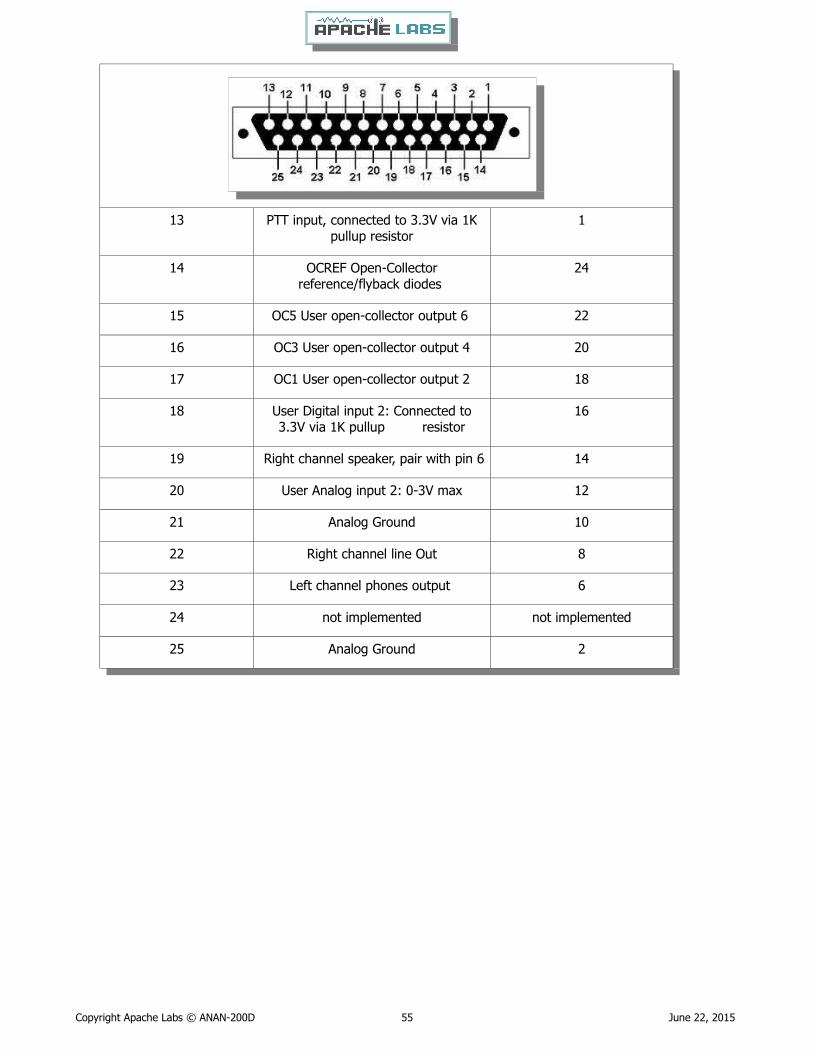
13 PTT input, connected to 3.3V via 1Kpullup resistor
1
14 OCREF Open-Collectorreference/flyback diodes
24
15 OC5 User open-collector output 6 22
16 OC3 User open-collector output 4 20
17 OC1 User open-collector output 2 18
18 User Digital input 2: Connected to3.3V via 1K pullup resistor
16
19 Right channel speaker, pair with pin 6 14
20 User Analog input 2: 0-3V max 12
21 Analog Ground 10
22 Right channel line Out 8
23 Left channel phones output 6
24 not implemented not implemented
25 Analog Ground 2
Copyright Apache Labs © ANAN-200D 55 June 22, 2015

MARS operation
In PowerSDR select Settings → General → Hardware Config → Region you will be able to select band limits by country or Region. Use care in selecting the “Extended” Region.
APIPA Automatic Private IP Addressing
Definition: APIPA is a DHCP failover mechanism for local networks. With APIPA, DHCP clients can obtain IP addresses when DHCP servers are non-functional. APIPA exists in all modern versions of Windows. If your new ANAN-200D Transceiver is connected directly to your PC, you will probably get an APIPA address.
If a DHCP server fails, APIPA allocates IP addresses in the private range 169.254.0.1 to 169.254.255.254. Whenthe DHCP server is again able to service requests, clients update their addresses automatically.
In APIPA, all devices use the default network mask 255.255.0.0 and all reside on the same subnet.
APIPA is enabled on all DHCP clients in Windows unless the computer's Registry is modified to disable it. APIPA can be enabled on individual network adapters.
Your current IP address, Netmask, Firmware revision, and MAC address are all clearly displayed on the main SETUP –→ General –→ Hardware Config menu panel [shown below].
Copyright Apache Labs © ANAN-200D 56 June 22, 2015
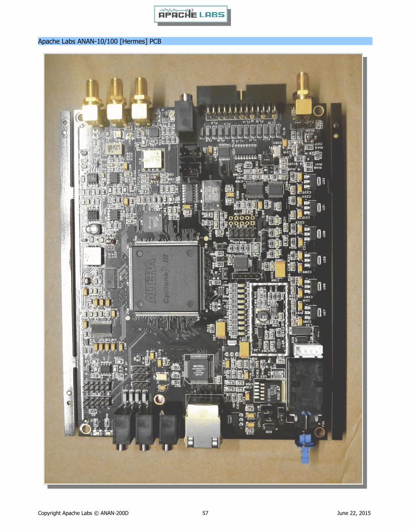
Apache Labs ANAN-10/100 [Hermes] PCB
Copyright Apache Labs © ANAN-200D 57 June 22, 2015

ANAN-100 jumper locations
Copyright Apache Labs © ANAN-200D 58 June 22, 2015

ANAN-100 PA Filter PCB
Copyright Apache Labs © ANAN-200D 59 June 22, 2015
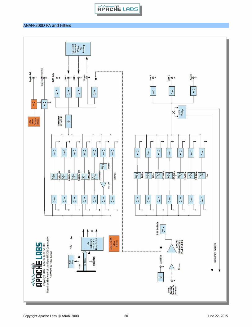
ANAN-200D PA and Filters
Copyright Apache Labs © ANAN-200D 60 June 22, 2015

Apache Labs ANAN-10/100 Block Diagram [courtesy VK6PH]
Copyright Apache Labs © ANAN-200D 61 June 22, 2015

NOTES
______________________________________________________________________________
______________________________________________________________________________
______________________________________________________________________________
______________________________________________________________________________
______________________________________________________________________________
______________________________________________________________________________
______________________________________________________________________________
______________________________________________________________________________
______________________________________________________________________________
______________________________________________________________________________
______________________________________________________________________________
______________________________________________________________________________
______________________________________________________________________________
______________________________________________________________________________
______________________________________________________________________________
______________________________________________________________________________
______________________________________________________________________________
______________________________________________________________________________
Copyright Apache Labs © ANAN-200D 62 June 22, 2015

Alphabetical Index
13.8vdc minimum, 25A.................................................................................1125vdc..........................................................................................................39800ma.........................................................................................................39Abhi Arunoday.............................................................................................52ACC/IO Port pinout......................................................................................54Adjusting mic gain.......................................................................................24ALC.............................................................................................................23ALC.............................................................................................................39ANAN back panel.........................................................................................13ANAN Front Panel........................................................................................12ANAN Hardware Requirements......................................................................11ANAN-200D Linear Amplifier PTT OUT...........................................................39Android.......................................................................................................11Antenna......................................................................................................34Antenna Control...........................................................................................34Antenna Control menu.................................................................................28Apache Labs ANAN-10/100 [Hermes] PCB.....................................................57Apache Labs International Support................................................................46Apache Schematics......................................................................................46Apache Service and Repair...........................................................................46Apache Yahoo Support Group.......................................................................46APIPA..........................................................................................................56Apollo..........................................................................................................52appdata.......................................................................................................44Audio Chain - How it works...........................................................................23BACKUP.......................................................................................................44Bill Tracey - KD5TFD....................................................................................52Break-in Delay.............................................................................................33CCS [Continuous Commercial Service] 30W...............................................8, 29CE and RTTE Certified....................................................................................7CFIR............................................................................................................53Chapter 1 - Introduction.................................................................................9Chapter 2 - Quick Start Instructions..............................................................14Chapter 3 – How to operate SSB Phone.........................................................22Chapter 4 – How to operate Digital modes.....................................................29Chapter 5 – How to operate CW....................................................................30Chapter 6 – How to Interface to your Linear Amplifier....................................39Chapter 7 – How to use PureSignal Adaptive predistortion..............................41Chapter 8 – How to install a new version of PowerSDR software.....................44
Copyright Apache Labs © ANAN-200D 63 June 22, 2015

Chapter 9 - How/when to install a new version of Apache Firmware................45CIC.............................................................................................................53Clarification CCS [30W]/ICAS [100W]........................................................8, 29COMPRESSOR..............................................................................................23Computer Performance.................................................................................49Computer with Full Duplex Ethernet NIC card..................................................9Connect a good antenna...............................................................................34Connecting a suitable Microphone.................................................................22Contributing members to the Hermes project.................................................52CORDIC.......................................................................................................53CTUNE........................................................................................................36cudaSDR.....................................................................................................11cuSDR.........................................................................................................11CW DELAY setting of 300ms.........................................................................33CW key terminated in 3.5mm........................................................................11CWU/CWL...................................................................................................31Damage to the radio caused in this manner is not covered by Warranty..........39DC Ammeter................................................................................................39DC Voltmeter...............................................................................................39Declarations of Conformity.............................................................................7Direct numeric input.....................................................................................35direct-down-conversion [DDC] receiver...........................................................9direct-up-conversion [DUC] transmitter...........................................................9Do not expect fast QSK................................................................................33Doug W5WC................................................................................................52DOWNWARD EXPANDER..............................................................................23Drag Mouse.................................................................................................36DUP............................................................................................................36Dxzone Software Catalog..............................................................................29Extended.....................................................................................................56FILTER........................................................................................................23Firmware revision.........................................................................................56Full Duplex Ethernet switch............................................................................9ghpsdr3.......................................................................................................11Graham - KE9H............................................................................................52GRAPHIC EQUALIZER...................................................................................23Hardware Setup...........................................................................................14Heat Dissipation.............................................................................................8Heterodyn...................................................................................................11How to test your PTT Linear Amplifier...........................................................39HPF/LPF Filters and switching in ANAN Transceiver........................................27
Copyright Apache Labs © ANAN-200D 64 June 22, 2015

HPSDRBootloader........................................................................................45HPSDRProgrammer......................................................................................45http://www.apache-labs.co...........................................................................45HUBS will NOT work.......................................................................................9Iambic A/B..................................................................................................30ICAS modes [Intermittent Commercial/Amateur Service] 100W PEP............8, 29Important....................................................................................................39Inter-Modulation Distortion...........................................................................41Introduction..................................................................................................9Java............................................................................................................11Joe K5SO.....................................................................................................52John Melton GØORX/N6LYT..........................................................................11Kevin Wheatley M0KHZ................................................................................52Keyboard commands....................................................................................35KISS Konsole...............................................................................................11Kjell Karlsen – LA2NI....................................................................................52LEVELER......................................................................................................23Linearity of an amplifier................................................................................41LOCK VFO...................................................................................................36Lyle Johnson - KK7P.....................................................................................52MAC address................................................................................................56manual calibration procedure........................................................................48Methods for tuning your Transceiver..............................................................35Methods for tuning your Transceiver to a frequency.......................................35MIC Adapters...............................................................................................22MIC GAIN....................................................................................................23microphone terminated in 3.5mm.................................................................11Microsoft .NET 4.x Framework......................................................................15Minimum Requirements..................................................................................9NON-linearity...............................................................................................41OpenHPSDR................................................................................................45OpenHPSDR Group.......................................................................................46OpenHPSDR Software..................................................................................51openhpsdrJ..................................................................................................11Operation tips................................................................................................8Original 2013 Users Guide............................................................................47Paddle Connection.......................................................................................31Panadapter set for DUP................................................................................43Phil Harman - VK6PH....................................................................................52pin 1 of the AUX I/O Ribbon connector..........................................................39pipelining.....................................................................................................53
Copyright Apache Labs © ANAN-200D 65 June 22, 2015
Plug............................................................................................................31Point and Click with Mouse...........................................................................35Pointers to reference materials......................................................................46posted on the Apache Web site.....................................................................45PowerSDR...................................................................................................11Program Files (x86)......................................................................................44PTT input.....................................................................................................39PureSignal...................................................................................................41PureSignal control window............................................................................41QSK............................................................................................................33Region.........................................................................................................56Roll Mouse Wheel.........................................................................................36Sample Rate................................................................................................30schematic pin numbers.................................................................................54Scotty Cowling - WA2DFI..............................................................................52Select Operating Frequency..........................................................................32Select the INFORMATION link.......................................................................41Select the Linearity tab.................................................................................41select your operating frequency....................................................................32Selecting Transmit Profile..............................................................................24Set Drive Level.............................................................................................32Set the DRIVE LEVEL....................................................................................32Setting up PowerSDR for Phone Operation.....................................................24Sidetone Level.............................................................................................34Software and download information..............................................................11Software Setup............................................................................................15suitable couplers....................................................................................39, 43The CORDIC Algorithm.................................................................................53Transmit Filter..............................................................................................26Transmitting................................................................................................26Tune...........................................................................................................26TUNE button to see your SWR and OUTPUT..................................................37Tuning.........................................................................................................35TWO TONE button.......................................................................................43Updates to the PowerSDR software...............................................................44Various directional coupler models are available.......................................40, 43VB-Audio.....................................................................................................22Virtual Audio Cable.......................................................................................22VK6PH.........................................................................................................53VK6PH example OpenCOllector BCD keying...................................................40VOX............................................................................................................26
Copyright Apache Labs © ANAN-200D 66 June 22, 2015

W1HKJ Fldigi...............................................................................................29Warranty.....................................................................................................50Warren Prat NRØV.......................................................................................42Warren Pratt NRØV PureSignal......................................................................41Windows Installation....................................................................................15XML DataBase..............................................................................................44..................................................................................9, 15, 23, 36, 46, 49, 51 Linear Amplifiers properly equipped with an RF Signal Sampler......................43“Automatic Tx Attenuation”...........................................................................43%appdata%................................................................................................44
Copyright Apache Labs © ANAN-200D 67 June 22, 2015