analytical coupled vibroacoustic modeling of membrane-type
TRANSCRIPT

Analytical coupled vibroacoustic modeling of membrane-typeacoustic metamaterials: Plate model
Yangyang Chena) and Guoliang Huanga),b)
Department of Systems Engineering, University of Arkansas at Little Rock, Little Rock, Arkansas 72204
Xiaoming Zhou and Gengkai HuKey Laboratory of Dynamics and Control of Flight Vehicle, Ministry of Education, School of AerospaceEngineering, Beijing Institute of Technology, Beijing 100081, China
Chin-Teh SunSchool of Aeronautics and Astronautics, Purdue University, West Lafayette, Indiana 47907
(Received 10 November 2013; revised 15 April 2014; accepted 24 October 2014)
By considering the elastic membrane’s dissipation, the membrane-type acoustic metamaterial
(MAM) has been demonstrated to be a super absorber for low-frequency sound. In the paper, a
theoretical vibroacoustic plate model is developed to reveal the sound energy absorption
mechanism within the MAM under a plane normal incidence. Based on the plate model in
conjunction with the point matching method, the in-plane strain energy of the membrane due to the
resonant and antiresonant motion of the attached masses can be accurately captured by solving the
coupled vibroacoustic integrodifferential equation. The sound absorption ability of the MAM is
quantitatively determined, which is also in good agreement with the prediction from the finite
element method. In particular, microstructure effects including eccentricity of the attached masses,
the depth, thickness, and loss factor of the membrane on sound absorption peak values are
discussed. VC 2014 Acoustical Society of America. [http://dx.doi.org/10.1121/1.4901706]
PACS number(s): 43.20.El, 43.20.Ks, 43.40.Dx, 43.50.Gf [ANN] Pages: 2926–2934
I. INTRODUCTION
The attenuation/absorption of low frequency sound is of
great interest for noise control. Common homogeneous
materials, such as foam and composite panels, usually
exhibit weak absorptions in the low frequency range, due to
their dissipative power being quadratic in material velocities.
Recently, membrane-type acoustic metamaterials (MAMs)
have been suggested to possess excellent acoustic properties
for sound insulation at the 100–1000 Hz frequency regime,
the most difficult regime as dictated by the mass density
law.1,2 This MAM comprises a pre-tensioned elastic rubber
membrane attached with only one rigid circular mass.
Nearly total reflection of low-frequency sound has been
achieved.1–5 To realize broadband wave attenuation and
enhance the wave dissipation, it is usually necessary to
increase the energy density inside the MAM through multi-
ple resonators. Motivated by this idea, a thin elastic mem-
brane decorated with designed patterns of multiple rigid
platelets was further suggested.6 The basic microstructure of
this MAM consists of a membrane with multiple attached
small heterogeneous masses acting as resonators with fixed
boundaries imposed by a relatively rigid grid. It was reported
that the one-layer of MAM can absorb 86% of the acoustic
waves at �170 Hz and can absorb 99% with two layers at
the lowest resonant frequency. However, the wave
attenuation/absorption mechanism is not well interpreted
and understood yet.
Issues about sound transmissions through membranes and
partitions have been intensively investigated for decades.7–10
The classical membrane theory has been used to approximately
govern the motion of the pre-stressed thin elastic membrane.11
However, the dissipative/absorbed sound power, which is pro-
portional to the total strain energy of the membrane,6 cannot
properly be calculated by the classical membrane theory,
because effects of the bending stiffness are neglected.
Therefore, the flexural plate theory for the MAM will be highly
needed for the purpose of the energy absorption calculation.
For vibrations of thin plates combining with varies
boundary conditions, governing equations and the Galerkin
procedure with several approximate series solutions have
been suggested.12,13 The problem of sound transmission
through a thin plate based on vibroacoustic plate model has
been solved with integrals of Green’s functions.14 Whereas,
modeling vibrations and sound dissipations of the MAMs
would address a challenging issue, in which a pre-stressed
clamped thin plate carrying finite attached masses of arbi-
trary shapes needs to be solved. Galerkin procedure and
Rayleigh–Ritz method are the most commonly used system-
atic approaches to study vibrations of plates with attached
masses, in which the bending stiffness of the attached mass
is usually ignored.15,16 However, different from those stud-
ies, bending stiffness of attached masses on MAMs cannot
be neglected. Instead, such attached masses would be rigid
compared with the thin rubber membrane. To properly cap-
ture effects of finite masses on the small deformation of the
membrane, the point matching scheme17 can be applied by
a)Present address: Department of Mechanical and Aerospace Engineering,
University of Missouri, Columbia, MO 65211.b)Author to whom correspondence should be addressed. Electronic mail:
2926 J. Acoust. Soc. Am. 136 (6), December 2014 0001-4966/2014/136(6)/2926/9/$30.00 VC 2014 Acoustical Society of America
Redistribution subject to ASA license or copyright; see http://acousticalsociety.org/content/terms. Download to IP: 152.14.136.96 On: Sat, 17 Jan 2015 23:58:49

using distributed point forces along the interfacial boundary
between masses and the membrane.11 Another issue about
the MAM is geometric nonlinearities of the rubber mem-
brane, in which in-plane pre-stresses are usually comparable
with the Young’s modulus. A plate theory considering incre-
mental deformation and initial stress has been developed for
orthotropic laminated plates.18
In this paper, to investigate sound absorptions of
MAMs, we will develop a vibroacoustic plate model to accu-
rately capture strain energy within the membrane. The initial
tension effect on the effective bending stiffness of the MAM
is determined by using the incremental energy method.
Eigenfrequencies and eigenmodes of the MAM are solved
by using point matching scheme, where the Galerkin proce-
dure with double cosine series expansions is selected.
Finally, the dissipative power is calculated through solving
the coupled vibroacoustic integrodifferential equation with
complex Young’s modulus and the modal superposition
method. Specifically, microstructure effects on sound
absorptions are quantitatively investigated, which include
eccentricities and numbers of masses, depth, and thickness
of the membrane and the membrane’s loss factor.
II. THEORETICAL PLATE MODEL
Consider now the unit cell of an MAM in a global
Cartesian coordinate system (x,y) with the origin O on the
lower left corner of the rectangular membrane, as shown in
Fig. 1(a), where the membrane is symmetrically attached by
several masses with respect to the central line of the mem-
brane along the x direction. Masses can be of arbitrary sym-
metric shapes with respect to the central line of the
membrane along the y direction. The number of masses is
denoted as S, and there are Is collocation points, applied with
point forces along edges of the sth mass. In the figure, the
membrane is subject to initial tension T per unit length
uniformly in both x and y directions. The thickness, width,
depth, and density per unit area of the membrane are denoted
as h, Lx, Ly, and qm, respectively. The ith collocation point on
the inner boundaries between the sth mass and the membrane
is denoted as [XðsÞi , Y
ðsÞi ] in the global Cartesian coordinate
system (x,y). In the study, we focus on the sound absorption of
the stretched MAM in a tube subject to a normally incident
plane sound wave, as shown in Fig. 1(b). Perfectly absorbing
boundary conditions are assumed in both ends of the tube so
that there will be no multiple reflected waves to the MAM.
A. Eigenvalue problem of the MAM
The attached masses are assumed to be rigid and
perfectly bonded to the rectangular membrane. To properly
capture effects of those masses on the deformation of the
membrane, the point matching scheme is applied such that
each mass can be represented by several point loadings on
the membrane along their interfacial boundaries.11 The
incremental energy method is used to consider the initial
stress effect, and the governing equation of the rectangular
membrane can be written as
D�r4w x; y; tð Þ � Tr2w x; y; tð Þ þ qm
@2w x; y; tð Þ@2t
¼XS
s¼1
XIs
i¼1
Fsð Þ
i tð Þdðx� Xsð Þ
i Þdðy� Ysð Þ
i Þ ; (1)
where D� ¼ Dþ ðr0h3=12Þ is the effective bending stiffness
with D and r0 being the bending stiffness and initial stress of
the membrane, which is derived in the Appendix, FðsÞi in the
right-hand side is the force loading at the ith collocation
points from the sth attached mass along sth inner boundaries,
and d is the Dirac delta function. Since only the steady-state
response field will be considered, the time factor eixt, which
applies to all the field variables, will be suppressed in the
paper. Then, FðsÞi becomes a constant to be determined. For a
clamped plate, the boundary conditions are
w ¼ @w
@x¼ 0; on x ¼ 0; x ¼ Lx; (2)
w ¼ @w
@y¼ 0; on y ¼ 0; y ¼ Ly: (3)
To solve Eq. (1), the Galerkin procedure is applied to seek
an approximate solution.13 Since a plane sound wave can
only induce symmetric modes on the MAM, we choose the
double cosine series expansion to satisfy boundary condi-
tions in Eqs. (2) and (3) as12,13
w ¼X1m¼1
X1n¼1
Wmnqmn; (4)
Wmn ¼ 1� cos2mpx
Lx
� �1� cos
2npy
Ly
� �: (5)
Substituting Eq. (4) into Eq. (1), multiplying each term by
Wmn, and integrating all terms over the domain (0 � x � Lx;
(a)
(b)
FIG. 1. (Color online) (a) The MAM symmetrically attached with multiple
masses of arbitrary symmetric shapes. (b) The MAM subjected to a normal
acoustic loading in a tube.
J. Acoust. Soc. Am., Vol. 136, No. 6, December 2014 Chen et al.: Modeling of membrane acoustic metamaterials 2927
Redistribution subject to ASA license or copyright; see http://acousticalsociety.org/content/terms. Download to IP: 152.14.136.96 On: Sat, 17 Jan 2015 23:58:49

0 � y � Ly), lead to a linear system of equations for qmn.13
Solutions of qmn can be expressed by the summation of
Fi(s)qmni
(s) from all the point loadings, where qmni(s) is the so-
lution of the linear system of equations with dðx� XðsÞi Þ
dðy� YðsÞi Þ in the right-hand side. Then, the solution to Eq.
(1) can be expressed as
w ¼XS
s¼1
XI
i¼1
FðsÞi Q
ðsÞi ; (6)
where QðsÞi ¼
P1m¼1
P1n¼1 q
ðsÞmni½1� cos ð2mpx=LxÞ�½1
� cos ð2npy=LyÞ�.The unknown loading Fi
(s) can be determined through
the inner boundary conditions between the membrane and
masses. The natural frequencies and mode shape functions
of the MAM can be determined by using the same techni-
ques in Ref. 11.
B. Vibroacoustic modeling of the MAM
Consider a plane sound wave is normally incident on
the MAM. According to the fact that the thickness of the
MAM is extremely small compared with the wavelength of
low-frequency sound in air, thickness effects of the MAM
can be ignored. The objective is to determine the dissipated
power within the MAM. The governing equation of the
acoustic excited membrane based on the plate theory can be
expressed as
D�r4w�Tr2w�x2qmw
¼p1jðz¼0Þ �p2jðz¼0Þ þXS
s¼1
XIs
i¼1
FðsÞi dðx�X
ðsÞi Þdðy�Y
ðsÞi Þ ;
(7)
where p1 and p2 are pressures on the left and right surfaces
of the MAM. It should be noted that damping effects in
forced vibration analyses are considered by assuming the
Young’s modulus of the membrane to be a complex number.
Then, D� is a complex number in Eq. (7).
By combining equations in the acoustic field,11 Eq. (7)
can be rewritten as
D�r4w� Tr2w� x2qmwþ 2ixqacahwi
� 2x2qa
ðLx
0
ðLy
0
Gdwdx�dy�
¼ 2PI þXS
s¼1
XIs
i¼1
FðsÞi dðx� X
ðsÞi Þdðy� Y
ðsÞi Þ ; (8)
in which the Green function G ¼ eikaS=4pSþ eikaS1=4pS1
with S ¼ffiffiffiffiffiffiffiffiffiffiffiffiffiffiffiffiffiffiffiffiffiffiffiffiffiffiffiffiffiffiffiffiffiffiffiffiffiffiffiffiffiffiffiffiffiffiffiffiffiffiffiffiffiffiffiffiffiffiffiffiffiffiffiffiffiðx� x�Þ2 þ ðy� y�Þ2 þ ðz� z�Þ2
q, S1
¼ffiffiffiffiffiffiffiffiffiffiffiffiffiffiffiffiffiffiffiffiffiffiffiffiffiffiffiffiffiffiffiffiffiffiffiffiffiffiffiffiffiffiffiffiffiffiffiffiffiffiffiffiffiffiffiffiffiffiffiffiffiffiffiffiffiðx� x�Þ2 þ ðy� y�Þ2 þ ðzþ z�Þ2
q; h�i denotes the aver-
age of the parameter; dw ¼ w� hwi; qa, ca, and ka are the
density of air, sound speed, and wave number of acoustic
waves in air, respectively. The displacement field in Eq. (8)
can then be solved by modal superposition method.11
For the application of the MAM, the acoustic
wavelength (k) for low frequency sound (50 to 1000 Hz) is
usually much larger than the dimension of the membrane
(k� Lx; Ly). According to Ref. 11, the higher order scat-
tered waves are caused by the deviation of the out-of-plane
displacement, and the longest wavelength along lateral direc-
tion is ðkkÞmax ¼ðLx; LyÞmax. Consequently, the lateral com-
ponent of the wave number of higher order scattered waves,
kk ¼ 2p=Lx, would be much greater than the maximum total
wave number, ðkaÞmax ¼ xmax=ca. As a result, the normal
component of the wave number (along the z direction) of
higher order scattered waves, kz ¼ffiffiffiffiffiffiffiffiffiffiffiffiffiffiffik2
a � k2k
q, is always an
imaginary number. Therefore, the higher order scattered
waves are eventually evanescent waves because the normal
(z) component of wave number is an imaginary number, and
their amplitude will decay exponentially along the normal
(z) direction.
Therefore, the far field transmission and reflection
coefficients for radiated plane waves of the MAM can be
expressed as11
~T ¼ PT
PI¼ ixqacahwi
PI; (9)
~R ¼ PR
PI; (10)
with the relation being
~R ¼ 1� ~T ; (11)
with PI, PR, and PT being complex amplitudes of incident,
reflected, and transmitted plane waves.
The intensity transmission and reflection coefficients
are11
TI ¼ j ~T j2; (12)
RI ¼ j ~Rj2: (13)
Therefore, the dissipated power of the MAM can be calcu-
lated as
AI ¼ 1�TI�RI ¼ 2ðReð ~TÞ�Reð ~TÞ2� Imð ~TÞ2Þ; (14)
where jReð ~TÞj � 1 and j Imð ~TÞj � 1 according to the defini-
tion of acoustic transmission and reflection coefficients.
Therefore, it can be easily derived that the maximum dissi-
pated power AI cannot be greater than 50% for any thin
MAM. It is noted that the air viscosity for the energy absorp-
tion are not taken into account in the current model.
III. VALIDATION OF THE THEORETICAL MODELING
To verify the developed vibroacoustic plate model,
acoustic and vibration properties of the MAM from the
current model are compared with those from the commercial
finite element software, COMSOL Multiphysics, in which
the acoustic-solid interaction with geometric nonlinearities
is selected. The MAM consists of a membrane
2928 J. Acoust. Soc. Am., Vol. 136, No. 6, December 2014 Chen et al.: Modeling of membrane acoustic metamaterials
Redistribution subject to ASA license or copyright; see http://acousticalsociety.org/content/terms. Download to IP: 152.14.136.96 On: Sat, 17 Jan 2015 23:58:49
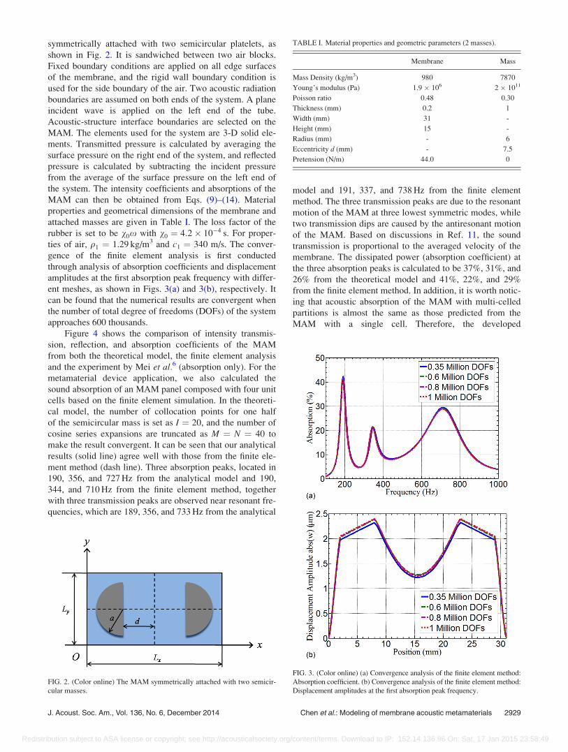
symmetrically attached with two semicircular platelets, as
shown in Fig. 2. It is sandwiched between two air blocks.
Fixed boundary conditions are applied on all edge surfaces
of the membrane, and the rigid wall boundary condition is
used for the side boundary of the air. Two acoustic radiation
boundaries are assumed on both ends of the system. A plane
incident wave is applied on the left end of the tube.
Acoustic-structure interface boundaries are selected on the
MAM. The elements used for the system are 3-D solid ele-
ments. Transmitted pressure is calculated by averaging the
surface pressure on the right end of the system, and reflected
pressure is calculated by subtracting the incident pressure
from the average of the surface pressure on the left end of
the system. The intensity coefficients and absorptions of the
MAM can then be obtained from Eqs. (9)–(14). Material
properties and geometrical dimensions of the membrane and
attached masses are given in Table I. The loss factor of the
rubber is set to be v0x with v0 ¼ 4:2 10�4 s. For proper-
ties of air, q1 ¼ 1.29 kg/m3 and c1 ¼ 340 m/s. The conver-
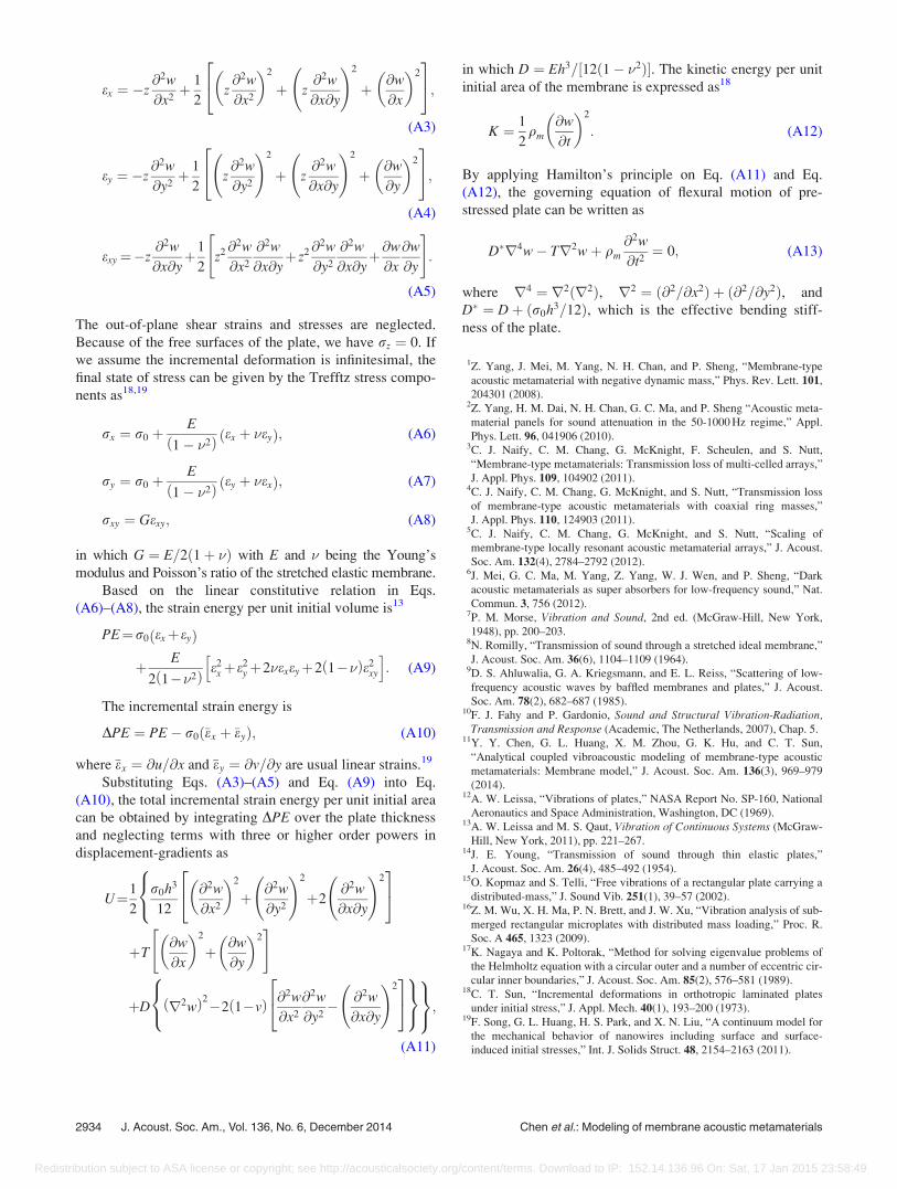
gence of the finite element analysis is first conducted
through analysis of absorption coefficients and displacement
amplitudes at the first absorption peak frequency with differ-
ent meshes, as shown in Figs. 3(a) and 3(b), respectively. It
can be found that the numerical results are convergent when
the number of total degree of freedoms (DOFs) of the system
approaches 600 thousands.
Figure 4 shows the comparison of intensity transmis-
sion, reflection, and absorption coefficients of the MAM
from both the theoretical model, the finite element analysis
and the experiment by Mei et al.6 (absorption only). For the
metamaterial device application, we also calculated the
sound absorption of an MAM panel composed with four unit
cells based on the finite element simulation. In the theoreti-
cal model, the number of collocation points for one half
of the semicircular mass is set as I ¼ 20, and the number of
cosine series expansions are truncated as M ¼ N ¼ 40 to
make the result convergent. It can be seen that our analytical
results (solid line) agree well with those from the finite ele-
ment method (dash line). Three absorption peaks, located in
190, 356, and 727 Hz from the analytical model and 190,
344, and 710 Hz from the finite element method, together
with three transmission peaks are observed near resonant fre-
quencies, which are 189, 356, and 733 Hz from the analytical
model and 191, 337, and 738 Hz from the finite element
method. The three transmission peaks are due to the resonant
motion of the MAM at three lowest symmetric modes, while
two transmission dips are caused by the antiresonant motion
of the MAM. Based on discussions in Ref. 11, the sound
transmission is proportional to the averaged velocity of the
membrane. The dissipated power (absorption coefficient) at
the three absorption peaks is calculated to be 37%, 31%, and
26% from the theoretical model and 41%, 22%, and 29%
from the finite element method. In addition, it is worth notic-
ing that acoustic absorption of the MAM with multi-celled
partitions is almost the same as those predicted from the
MAM with a single cell. Therefore, the developed
FIG. 2. (Color online) The MAM symmetrically attached with two semicir-
cular masses.
TABLE I. Material properties and geometric parameters (2 masses).
Membrane Mass
Mass Density (kg/m3) 980 7870
Young’s modulus (Pa) 1.9 106 2 1011
Poisson ratio 0.48 0.30
Thickness (mm) 0.2 1
Width (mm) 31 -
Height (mm) 15 -
Radius (mm) - 6
Eccentricity d (mm) - 7.5
Pretension (N/m) 44.0 0
FIG. 3. (Color online) (a) Convergence analysis of the finite element method:
Absorption coefficient. (b) Convergence analysis of the finite element method:
Displacement amplitudes at the first absorption peak frequency.
J. Acoust. Soc. Am., Vol. 136, No. 6, December 2014 Chen et al.: Modeling of membrane acoustic metamaterials 2929
Redistribution subject to ASA license or copyright; see http://acousticalsociety.org/content/terms. Download to IP: 152.14.136.96 On: Sat, 17 Jan 2015 23:58:49

theoretical model can be applied for the vibroacoustic analy-
sis of the metamaterial device with multi-cells.
The loss factor is usually determined by fitting theoreti-
cal absorptions with experimental absorptions. Effects of
loss factors will be discussed in the next section. However,
as illustrated in Eq. (14), dissipations would not be greater
than 50% with any loss factors. The comparison of wave
absorption predicted from theoretical model, finite element
method, and experimental measurements is added in Fig. 4.
The main trend of the experimental measurement is almost
the same as those from theoretical model and finite element
simulations. For example, the frequencies of the three sound
absorption peaks predicted from the theoretical model and
experimental testing are in very good agreement. However,
difference of wave absorption magnitude prediction of the
metamaterial from the theoretical model and experimental
testing can also be obviously observed, which needs to be
studied further. The difference may be attributed to the fol-
lowing two facts. First, the higher experimentally measured
sound absorption could be caused by multi-reflections
between the sound speaker and the MAM in the left tube,
which is not considered in the current model. Another reason
of the higher sound absorption in the experiment could be
the imperfect symmetry of attached masses, which can
excite asymmetric modes. However, these asymmetric-
induced modes are not taken into account in both the analyti-
cal model and the finite element method.
To validate the capacity of the current model for the
energy absorption, the displacement amplitude and strain
energy density within the mid-plane of the membrane at
three absorption peak frequencies predicted from the current
model and the finite element method are compared at Fig. 5
and Fig. 6. The images in Fig. 5(a) and Fig. 6(a) are from the
analytical model, and the images in Fig. 5(b) and Fig. 6(b)
are from the finite element method. The strain energy density
within the mid-plane of the membrane in the 2-D theoretical
model is calculated by averaging the strain energy density
within the plate through the thickness. The color bar in the
figure represents a logarithmic scale for the strain energy
density. Good agreement between the analytical and numeri-
cal results is observed in both Figs. 5 and 6. As shown in
Fig. 5, for the MAM with two attached semicircular masses,
the first absorption peak is caused by both the translational
and rotational motion of the masses, whereas the second
peak is mainly caused by the rotational motion of the
masses. The third peak is caused by the strong vibration of
the partial membrane between the two masses. From Fig. 6,
it can be seen that the strain energy density in the perimeter
FIG. 4. (Color online) Comparison of intensity transmission, reflection and
absorption coefficients of the MAM with two semicircular masses between
analytical, finite element (one unit cell and four unit cell panel) and experi-
mental results (absorption only).
FIG. 5. (Color online) Validation of
displacement amplitude at absorption
peak frequencies of the MAM with
two semicircular masses.
2930 J. Acoust. Soc. Am., Vol. 136, No. 6, December 2014 Chen et al.: Modeling of membrane acoustic metamaterials
Redistribution subject to ASA license or copyright; see http://acousticalsociety.org/content/terms. Download to IP: 152.14.136.96 On: Sat, 17 Jan 2015 23:58:49

and clamped regions of the membrane is extremely much
higher than the other regions by about three orders of magni-
tude at all the three absorption peaks. According to the fact
that the local dissipated power is proportional to the strain
energy density, most of the absorbed sound energy would be
dissipated in these regions. The largest absolute discrepancy
(around 10%) of the absorption at the second peak can be
attributed to the approximation of the Kirchhoff hypothesis,
which assumes that in-plane shear stains are dependent on
out-of-plane displacement. Overall, it is clearly evident that
the proposed model can accurately capture the sound energy
dissipation behavior of the MAM as those in the finite ele-
ment method.
IV. RESULTS AND DISCUSSIONS
Based on the developed analytical model, we will inves-
tigate effects of the eccentricity of masses, the width and
thickness of the membrane and loss factors on the sound
absorption behavior of the above MAM. The MAM attached
with multiple semicircular masses will be also considered.
The purpose of this study is to develop an accurate and
highly effective analytical tool to optimize the design of
MAMs on sound dissipations.
A. The MAM with two semicircular masses
In practice, eccentricity of attached masses is a critical
parameter that can be easily changed to fulfill design require-
ment of an MAM. Figure 7 shows effects of eccentricities of
two symmetric semicircular masses on sound absorptions of
the MAM. In the figure, the material and geometric proper-
ties of the MAM are the same as listed in Table I with
v0 ¼ 4:2 10�4 s, and only the eccentricity of attached
masses is changed. It can be found that the first absorption
peak value is increased with the increase of the eccentricity.
However, the third absorption peak value is decreased with
the increase of the eccentricity. It is understandable that
when the eccentricity is increased, the membrane curvature
around circular edges of attached masses and two vertically
clamped edges will become larger at the first resonant fre-
quency, where masses vibrate strongly with both transla-
tional and rotational motion. The strain energy density in
these regions will then become higher, therefore, the total
absorption will increase at the first resonance frequency. The
decrease of the third peak is caused by the reduced mem-
brane curvature along straight edges of masses, in which the
highest strain energy density concentrates by a strong vibra-
tion of the membrane. The second peak is increased slightly,
when d is changed from 6.5 to 7.5 mm, and is reduced from
31% to 18%, when d is changed from 7.5 to 8.5 mm. The
sharp drop of the second peak is due to the decrease of rota-
tional displacement amplitudes of attached masses and mem-
brane curvatures in parameter regions. It should be
mentioned that the eccentricity can also affect the resonant
frequencies of the MAM.
The membrane’s width effects on sound absorption of
the MAM are illustrated in Fig. 8. In the figure, the material
and geometric properties of the MAM are the same as listed
in Table I with v0 ¼ 4:2 10�4 s, and only the width of the
FIG. 6. (Color online) Validation of
strain energy density at absorption
peak frequencies of the MAM with
two semicircular masses.
FIG. 7. (Color online) Effects of masses’ eccentricities to sound absorption
of the MAM with two semicircular masses.
J. Acoust. Soc. Am., Vol. 136, No. 6, December 2014 Chen et al.: Modeling of membrane acoustic metamaterials 2931
Redistribution subject to ASA license or copyright; see http://acousticalsociety.org/content/terms. Download to IP: 152.14.136.96 On: Sat, 17 Jan 2015 23:58:49

membrane is changed. As shown in the figure, when the
width is reduced from 16 to 14 mm, the first absorption peak
is raised from 28% to 47%, and the third peak is increased
from 25% to 29%, whereas the second peak is decreased
from 34% to 27%. All of the three resonant frequencies will
also be increased slightly. The increased absorption values at
the first and third resonant frequencies are caused by the
increased curvature in sharp corners of masses. The
decreased absorption is due to the reduced rotational dis-
placement amplitudes of attached masses at the second reso-
nant frequency.
Figure 9 shows effects of membrane’s thickness on sound
absorption of the MAM. In the figure, the material and geo-
metric properties of the AM are the same as listed in Table I
with v0 ¼ 4:2 10�4 s, only the thickness of the membrane
is changed. It can be seen that the first and third sound absorp-
tion peaks are increased when the membrane becomes thicker.
The second sound absorption peak, however, is reduced. The
increased absorptions can be attributed to the increase of the
bending stiffness of the plate, which is proportional to the
strain energy density of the plate. Nevertheless, the thicker
membrane would confine rotational motion of attached
masses, and eventually the sound absorption of the MAM will
be reduced at the second resonant frequency.
Figure 10 illustrates effects of v0, a constant of the loss
factor, on sound absorption of the MAM. In the figure,
material and geometric properties of the MAM are the same
as listed in Table I, only v0 is changed. It can be easily
observed that the 50% limit of sound absorption of the
MAM is further verified numerically. As expected, absorp-
tion at most of the frequency range can be increased by rais-
ing the value of v0, until the absorption reaches its limit. It is
understandable that the larger loss factor usually means
more energy can be damped and absorbed within the mem-
brane. However, when the dissipated power has reached the
limit with the increase of v0, it cannot be increased anymore,
and it will be decreased instead with the increase of v0.
B. The MAM with four semicircular masses
Sound absorption of the MAM attached with four semi-
circular masses, as shown in Fig. 11, are investigated by the
developed vibroacoustic plate model. In the figure, the
eccentricities of inner and outer masses, d1 and d2 and the
length of the membrane are selected as 7.5, 16.5, and
49.0 mm, respectively. Other material and geometric proper-
ties of the MAM are the same as listed in Table I. Sound
absorptions of the MAM are plotted in Fig. 12 in function of
v0. When four attached masses are used, two additional
absorption peaks are obviously observed for
v0 ¼ 2:1 10�4 s. It should be mentioned that the second
peak becomes less distinct when v0 is above 4.2E-4 s.
Effects of v0 on the other peaks are similar as those of the
MAM with two attached masses. The displacement ampli-
tude fields in the MAM at the five peak frequencies are
shown in Fig. 13. It can be found that the first four absorp-
tion peaks of the MAM are caused by both translational and
FIG. 8. (Color online) Effects of membrane’s width to sound absorption of
the MAM with two semicircular masses.
FIG. 9. (Color online) Effects of membrane’s thickness to sound absorption
of the MAM with two semicircular masses.
FIG. 10. (Color online) Effects of membrane’s loss factors to sound absorp-
tion of the MAM with two semicircular masses.
FIG. 11. (Color online) The MAM symmetrically attached with four semi-
circular masses.
2932 J. Acoust. Soc. Am., Vol. 136, No. 6, December 2014 Chen et al.: Modeling of membrane acoustic metamaterials
Redistribution subject to ASA license or copyright; see http://acousticalsociety.org/content/terms. Download to IP: 152.14.136.96 On: Sat, 17 Jan 2015 23:58:49

rotational motions of the attached masses, whereby the fifth
absorption peak is caused by a strong vibration of the mem-
brane. It can be concluded that the more masses the MAM
attached, the more resonant frequencies can be found in the
low frequency range, which can produce more sound absorp-
tion peaks and make the spectrum of sound absorptions
broader eventually.
V. CONCLUSIONS
The vibroacoustic plate model is first developed to study
sound absorptions and energy dissipations within MAMs
under a normal incidence. The incremental energy method is
applied to derive the effective bending stiffness of plates
with initial in-plane stresses. Based on the plate model in
conjunction with the point matching method, the in-plane
strain energy of the membrane due to the resonant and anti-
resonant motion of the attached masses can be accurately
captured by solving the coupled vibroacoustic integrodiffer-
ential equation. Therefore, the sound absorption of the
MAM is obtained and discussed. The accuracy of the model
is verified by comparison with the finite element method.
Finally, parameter studies including masses’ eccentricities
and the width, thickness and the loss factor of the membrane
on the sound absorption behaviors of the MAM with multi-
ple attached masses are initially demonstrated.
ACKNOWLEDGMENTS
The authors would like to thank Dr. Ping Sheng from
Hong Kong University of Science and Technology and Dr.
Jun Mei from South China University of Technology for
their comments and discussions. This work was supported in
part by the Air Force Office of Scientific Research under
Grant No. AF 9550-10-0061 with Program Manager Dr.
Byung-Lip (Les) Lee, the National Science Foundation
under award No. EPS-1003970, and by National Natural
Science Foundation of China under Grants 11221202,
11290153, and 11172038.
APPENDIX: EFFECTIVE BENDING STIFFNESS OF THEPLATE WITH INITIAL STRESS
The flexural motion of a pre-tensioned elastic rubber
membrane is described by a thin plate model with uniform
in-plane initial stress, r0 ¼ T=h, in both x and y directions,
and the magnitude of initial stresses are comparable with the
Young’s modulus of the rubber membrane. According to the
Kirchhoff hypothesis,13 displacement fields in x and y direc-
tions can be expressed, respectively, as
u x; y; z; tð Þ ¼ �z@w x; y; tð Þ
@x; (A1)
v x; y; z; tð Þ ¼ �z@w x; y; tð Þ
@y; (A2)
where z denotes the coordinate measured from the neutral
plane of the membrane, and w is the out-of-plane displace-
ment of this neutral plane. Green-Lagrangian in-plane strains
are considered and expressed by18
FIG. 12. (Color online) Sound absorption of the MAM with four semicircu-
lar masses with different loss factors.
FIG. 13. (Color online) Displacement amplitude at absorption peak frequen-
cies of the MAM with four semicircular masses.
J. Acoust. Soc. Am., Vol. 136, No. 6, December 2014 Chen et al.: Modeling of membrane acoustic metamaterials 2933
Redistribution subject to ASA license or copyright; see http://acousticalsociety.org/content/terms. Download to IP: 152.14.136.96 On: Sat, 17 Jan 2015 23:58:49
ex ¼ �z@2w
@x2þ 1
2z@2w
@x2
� �2
þ z@2w
@x@y
!2
þ @w
@x
� �2
24
35;
(A3)
ey ¼ �z@2w
@y2þ 1
2z@2w
@y2
!2
þ z@2w
@x@y
!2
þ @w
@y
� �2
24
35;
(A4)
exy¼�z@2w
@x@yþ1
2z2@
2w
@x2
@2w
@x@yþ z2@
2w
@y2
@2w
@x@yþ@w
@x
@w
@y
" #:
(A5)
The out-of-plane shear strains and stresses are neglected.
Because of the free surfaces of the plate, we have rz ¼ 0. If
we assume the incremental deformation is infinitesimal, the
final state of stress can be given by the Trefftz stress compo-
nents as18,19
rx ¼ r0 þE
1� �2ð Þ ex þ �eyð Þ; (A6)
ry ¼ r0 þE
1� �2ð Þ ey þ �exð Þ; (A7)
rxy ¼ Gexy; (A8)
in which G ¼ E=2ð1þ �Þ with E and � being the Young’s
modulus and Poisson’s ratio of the stretched elastic membrane.
Based on the linear constitutive relation in Eqs.
(A6)–(A8), the strain energy per unit initial volume is13
PE¼r0 exþeyð Þ
þ E
2 1��2ð Þ e2xþe2
yþ2�exeyþ2 1��ð Þe2xy
h i: (A9)
The incremental strain energy is
DPE ¼ PE� r0ð�ex þ �eyÞ; (A10)
where �ex ¼ @u=@x and �ey ¼ @v=@y are usual linear strains.19
Substituting Eqs. (A3)–(A5) and Eq. (A9) into Eq.
(A10), the total incremental strain energy per unit initial area
can be obtained by integrating DPE over the plate thickness
and neglecting terms with three or higher order powers in
displacement-gradients as
U¼1
2
r0h3
12
@2w
@x2
� �2
þ @2w
@y2
!2
þ2@2w
@x@y
!224
35
8<:þT
@w
@x
� �2
þ @w
@y
� �2" #
þD r2wð Þ2�2 1�vð Þ @2w
@x2
@2w
@y2� @2w
@x@y
!224
35
8<:
9=;9=;;
(A11)
in which D ¼ Eh3=½12ð1� �2Þ�. The kinetic energy per unit
initial area of the membrane is expressed as18
K ¼ 1
2qm
@w
@t
� �2
: (A12)
By applying Hamilton’s principle on Eq. (A11) and Eq.
(A12), the governing equation of flexural motion of pre-
stressed plate can be written as
D�r4w� Tr2wþ qm
@2w
@t2¼ 0; (A13)
where r4 ¼ r2ðr2Þ, r2 ¼ ð@2=@x2Þ þ ð@2=@y2Þ, and
D� ¼ Dþ ðr0h3=12Þ, which is the effective bending stiff-
ness of the plate.
1Z. Yang, J. Mei, M. Yang, N. H. Chan, and P. Sheng, “Membrane-type
acoustic metamaterial with negative dynamic mass,” Phys. Rev. Lett. 101,
204301 (2008).2Z. Yang, H. M. Dai, N. H. Chan, G. C. Ma, and P. Sheng “Acoustic meta-
material panels for sound attenuation in the 50-1000 Hz regime,” Appl.
Phys. Lett. 96, 041906 (2010).3C. J. Naify, C. M. Chang, G. McKnight, F. Scheulen, and S. Nutt,
“Membrane-type metamaterials: Transmission loss of multi-celled arrays,”
J. Appl. Phys. 109, 104902 (2011).4C. J. Naify, C. M. Chang, G. McKnight, and S. Nutt, “Transmission loss
of membrane-type acoustic metamaterials with coaxial ring masses,”
J. Appl. Phys. 110, 124903 (2011).5C. J. Naify, C. M. Chang, G. McKnight, and S. Nutt, “Scaling of
membrane-type locally resonant acoustic metamaterial arrays,” J. Acoust.
Soc. Am. 132(4), 2784–2792 (2012).6J. Mei, G. C. Ma, M. Yang, Z. Yang, W. J. Wen, and P. Sheng, “Dark
acoustic metamaterials as super absorbers for low-frequency sound,” Nat.
Commun. 3, 756 (2012).7P. M. Morse, Vibration and Sound, 2nd ed. (McGraw-Hill, New York,
1948), pp. 200–203.8N. Romilly, “Transmission of sound through a stretched ideal membrane,”
J. Acoust. Soc. Am. 36(6), 1104–1109 (1964).9D. S. Ahluwalia, G. A. Kriegsmann, and E. L. Reiss, “Scattering of low-
frequency acoustic waves by baffled membranes and plates,” J. Acoust.
Soc. Am. 78(2), 682–687 (1985).10F. J. Fahy and P. Gardonio, Sound and Structural Vibration-Radiation,
Transmission and Response (Academic, The Netherlands, 2007), Chap. 5.11Y. Y. Chen, G. L. Huang, X. M. Zhou, G. K. Hu, and C. T. Sun,
“Analytical coupled vibroacoustic modeling of membrane-type acoustic
metamaterials: Membrane model,” J. Acoust. Soc. Am. 136(3), 969–979
(2014).12A. W. Leissa, “Vibrations of plates,” NASA Report No. SP-160, National
Aeronautics and Space Administration, Washington, DC (1969).13A. W. Leissa and M. S. Qaut, Vibration of Continuous Systems (McGraw-
Hill, New York, 2011), pp. 221–267.14J. E. Young, “Transmission of sound through thin elastic plates,”
J. Acoust. Soc. Am. 26(4), 485–492 (1954).15O. Kopmaz and S. Telli, “Free vibrations of a rectangular plate carrying a
distributed-mass,” J. Sound Vib. 251(1), 39–57 (2002).16Z. M. Wu, X. H. Ma, P. N. Brett, and J. W. Xu, “Vibration analysis of sub-
merged rectangular microplates with distributed mass loading,” Proc. R.
Soc. A 465, 1323 (2009).17K. Nagaya and K. Poltorak, “Method for solving eigenvalue problems of
the Helmholtz equation with a circular outer and a number of eccentric cir-
cular inner boundaries,” J. Acoust. Soc. Am. 85(2), 576–581 (1989).18C. T. Sun, “Incremental deformations in orthotropic laminated plates
under initial stress,” J. Appl. Mech. 40(1), 193–200 (1973).19F. Song, G. L. Huang, H. S. Park, and X. N. Liu, “A continuum model for
the mechanical behavior of nanowires including surface and surface-
induced initial stresses,” Int. J. Solids Struct. 48, 2154–2163 (2011).
2934 J. Acoust. Soc. Am., Vol. 136, No. 6, December 2014 Chen et al.: Modeling of membrane acoustic metamaterials
Redistribution subject to ASA license or copyright; see http://acousticalsociety.org/content/terms. Download to IP: 152.14.136.96 On: Sat, 17 Jan 2015 23:58:49