analysis on the operation of gas regulators and
TRANSCRIPT
Abstract— This paper presents an analysis of the operation of
natural gas regulators in terms of their time constants. At the same time, proposing a solution to optimize the functioning of regulators by reducing the time constants and increasing the amplification factor of the composition controller’s actuators. This optimization was achieved by changing the building shape of spring control and by changing the material of construction of the control membrane. Studies were performed using the techniques of CAD drawing-design-optimization (Computer Aided Design) and CAE (Computer Aided Engineering) for the development of 3D representation and controller components for simulation by finite element method, FEM. To optimize the time constant which allows a faster step response regulator have been changes to the arc control and to optimize the amplification factor were surveyed on the membrane control of the gas regulator. Optimizing the operation of the gas regulator is required to: increase reliability, operational safety, the life of the regulator and to reduce noise and vibration levels that occur in the dynamic regime of functioning.
Keywords—automatic system, actuator, model, natural gas, regulator
I. INTRODUCTION
as regulators for natural gas are major equipment, their primary role is to control and maintain optimal
parameters highly pressurized gas during its movement through the transport network.
The work has been funded by the Sectoral Operational Programme Human Resources Development 2007-2013 of the Romanian Ministry of Labour, Family and Social Protection through the Financial Agreement POSDRU/6/1.5/S/16.
Adelin Ionel Tuta is with Faculty of Engineering from Eftimie Murgu University of Resita, Piata Traian Vuia 1-4, 320085, Resita, Romania, (phone: +40-722-300-075; fax: +40-255-207501; e-mail: [email protected]).
Ion Vela is with Faculty of Engineering from Eftimie Murgu University of Resita, Piata Traian Vuia 1-4, 320085, Resita, Romania, (e-mail: [email protected]).
Marius Tufoi is with Center of Advanced Research, Design and Technology from from Eftimie Murgu University of Resita, Piata Traian Vuia 1-4, 320085, Resita, Romania, (e-mail: [email protected]).
Daniel Amariei is with Center of Advanced Research, Design and Technology from from Eftimie Murgu University of Resita, Piata Traian Vuia 1-4, 320085, Resita, Romania, (e-mail: [email protected]).
Cornel Mituletu is with Center of Advanced Research, Design and Technology from from Eftimie Murgu University of Resita, Piata Traian Vuia 1-4, 320085, Resita, Romania, (e-mail: [email protected]).
Lenuta Suciu is with Faculty of Engineering from Eftimie Murgu University of Resita, Piata Traian Vuia 1-4, 320085, Resita, Romania, (e-mail: [email protected]).
At the entrances to cities, industrial sites or other beneficiaries and end users, regulators are those that are designed to relieve the transport of gas to the conditions imposed on distribution operations, specifically to the classification in the distribution pressure parameters. The regulators ensure consistent and measurable gas pressure, though regulators are those that control gas, the last step prior domestic or industrial consumption. Some constructive regulatory schemes are presented in the following fig. 1 and 2.
Fig. 1 High pressure natural gas regulators
Fig. 2 Low pressure natural gas regulators
Pneumatic pressure regulators are pneumatic equipment that
performed automatically and continuously adjusting of the gas output pressure of the regulator and maintains pre-established limits (prescribed) to change (amendment) inlet pressure and gas flow [1].
It follows therefore, that pressure regulators are pressure control systems of the closed circuit, and systems have their own structure, whose operation is based on misconduct by law adjustment and comparison [2]. A natural gas pressure regulator is equipped with pneumatic actuators regulating
Analysis on the operation of gas regulators and optimization of their operation
A. I. Tuta, I. Vela, M. Tufoi, D. Amariei, C. Mituletu and L. Suciu
G
Advances in Control, Chemical Engineering, Civil Engineering and Mechanical Engineering
ISBN: 978-960-474-251-6 125
bodies, and represents an automatic system, figure 3.
Fig. 3 Automatic system
where: P is process; C- regulator; EE- actuator; T-
transducer; Ti- input transducer; Ye-size output; Yi-prescribed value for y; r-size of the reaction; i - input size; u-control; m-size of execution; p-disturbance. Automatic pressure control system of figure 3 is aimed to maintain the value of output size, Ye, of process, equal or closer to the desired value, prescribed Ye ± ∆Ye under the action of disturbances “p”. Random variations in time leading to differences Ye-Yi in system, through variables “i” and “r” respectively “i-r” violations are processed by the controller C, which generates command “u”, on the actuator EE. Actuators under control action “u” change size of drive “m” until deviations are eliminated from the system.
II. THEORETICAL CONSIDERATIONS AND STUDIES
A. Dynamic mathematical model of pressure regulators
Natural gas pressure regulators are equipped with regulating bodies and pneumatic actuators and are an automatic adjustment of which dynamic mathematical model is given by relations (1) and (2) [3].
)( 212112
2
2 PPbPmbHdt
Hda
dt
Hda ∆−∆+∆=∆+∆+∆ (1)
PcPmdt
Pmdas ∆=∆+∆ (2)
where the differential equation (2) was written in relation to possible deviations of the control gas pressure.
Assuming:
-Time constant k
ma =2
of equation (1) is low and can be
neglected ; -Variation in time of pressures )(1 tP∆ and )(2 tP∆ are
constants, and the b2 coefficient of amplification product will have a negligible value (insignificant)[4].
Based on these assumptions and technical considerations, the system of relations (1) and (2) shall have the following form:
PmbHdt
Hda ∆=∆+∆
11 (3)
PcPmdt
Pmdas ∆=∆+∆ (4)
From equation (1) results as of equal value:
∆+∆=∆ Hdt
Hda
bPm 1
1
1 (5)
and equation (5) is inserted in equation (2), resulting:
PcH
dt
Hda
bdt
Hd
dt
Hda
b
as ∆=
∆+∆+
∆+∆1
12
2
11
1
PcbH
dt
Hda
dt
Hda
dt
Hdaa ss ∆=∆+∆+∆+∆
112
2
1
( ) PcbHdt
Hdaa
dt
Hdaa ss ∆=∆+∆++∆
112
2
1 (6)
This second order differential equation (6) represents the mathematical model, which expresses relatively accurate, dynamic pressure regulators equipped with pneumatic diaphragm actuators.
B. Model’s studies
For a helically spring actuator in gas regulator model S300 (figure4) in which Rm = 35mm, d = 14mm, n = 10, number of turns (figure 5).
Fig. 4 Gas regulator model S 300
Amplification coefficient b is calculated from equation (7).
Fig. 5 Helically spring deflection
( ) bFFGd
nD
dG
nDFRR
GI
LMRy mmmm
p
tm =⋅=
⋅⋅⋅==
4
3
4
8
32/ππ (7)
and then bow arrows, for different values of force developed on command membrane by control pressure Pc. Solution: using for the transverse elasticity modulus the value G = 8.1 x10⁵daN/cm2= 0.81 x 10¹¹N/m2 is calculated directly:
×=××
××== −
N
m
Gd
nRb m 5
411
3
4
3
10882,0014,01081,0
035,0106464 (8)
Advances in Control, Chemical Engineering, Civil Engineering and Mechanical Engineering
ISBN: 978-960-474-251-6 126

The arc arrow under the action of force F=353daN
mmmFby 10,310311,0353010882,0 5 ==××=×= − (9)
The arc arrows under the action of various values of developed force on the PC control membrane, are:
daNFbarPc PC 141;2,0 == (prestressed spring);
mmmH 44,1201244,0141010882,0 51 ==××= −
(10)
daNFbarPc PC 282;4,0 ==
mmmH 87,2402487,0282010882,0 52 ==××= −
daNFbarPc PC 706;1 ==
mmmH 3,620623,0706010882,0 53 ==××= −
Actual value (useful), of the servo-drive stroke is so:
,509,494,123,6213100 mmmmHHH ≈=−=−= (11)
is current value for actuator S300.
C. Optimization of operation of the pressure regulator
Optimization of operation of the pressure regulator for natural gas refers to optimize time constants their downwards. They used CAD and CAE techniques for drawing, design and optimization of the pressure. Studies were also conducted using the finite element method for simulating the deformations that occur in order helical compression spring (reaction) of the controller and also to control the simulation of membrane deformation. To optimize the time constant, the authors have proposed the modification of the geometric shape of the helical spring based on values obtained from classical helical spring deformation simulation with finite element. These values have been validated by experimental measurements performed on testing-calibration bench of regulators. The authors propose the changing of the geometric shape of the arc in order to reduce the time constant of automatic control system. Classical spring and the spring with new form are shown in Figures 6.
Fig. 6 Classical form and new shape of helical springs
New form of the helical spring command has the advantage that at small changes of pressure on the membrane control of the regulator, these variations are taken from the site with smaller diameter of the arc where it compresses sooner because of the variable diameter of the spring. Large and slow variations of pressure on the membrane order are taken of the larger diameter of the proposed helical spring. This leads to a faster and more specific response (depending on the type of variation of input pressure) of the regulator, and thus reduces the time constants. In Figure 7 and 8 are performed simulations for the classical spring and for new proposed control spring.
Fig. 7 Simulation for classical spring with FEM
Fig. 8 Simulation for new shape of spring with FEM
Optimization of the time constant of the pressure regulator downwards can be done by modifying the shape and material from which is made the control membrane of the controller. Usually, the membrane control gas pressure regulators are made of rubber. Making by rubber of the membrane control offers the following advantages: low production cost, increased flexibility, reduced weight relative to volume, light manufacturing technology through vulcanization. Disadvantages of the rubber membranes are reduced reliability
Advances in Control, Chemical Engineering, Civil Engineering and Mechanical Engineering
ISBN: 978-960-474-251-6 127

due to the effect of aging and large displacements of the membrane, relatively small changes in pressure, leading to larger membrane and hence the regulator body, limitations on the operating temperature ranges regulators due to stiffening of rubber at low temperatures. To remove the above disadvantages to the use of rubber in the construction of membranes, the authors propose making control membranes using other materials. Materials used are brass and neoprene. Using these materials in place of rubber without the following benefits: a) In case of neoprene, it reduces the specific weight of the membrane; it can extend the temperature range of use of controllers; increases the reliability of membrane and thus reliability of the controller; b) In case of brass for use in building control membrane, increases the pressure regulator working at the same size of housing; increase the operating temperature range of the controller; gauge regulator may be reduced for the same range of pressure with the regulator, equipped with rubber membrane; increase the reliability controller. In fig. 8 is presented the membrane or diaphragm models proposed by authors, which are made from rubber, brass and neoprene.
D. Simulation with springs and membranes
Figures 9, 10 and 11 shows models of membranes made of rubber, neoprene and brass necessary to simulate the operation of membrane-spring mechanism.
Fig. 9 Rubber membrane
This mechanism is shown in Figures 12, 13 and 14, separately for each type of material used to achieve membrane. The study in particular, is based on the actual gas regulator S300. Studying component parts and using experimental data obtained on test bench, the authors have created this model to study simulation with finite element method. The finite element method (FEM) (its practical application often known as finite element analysis (FEA)) is a numerical technique for finding approximate solutions of partial differential equations (PDE) as well as of integral equations. The solution approach is based either on eliminating the differential equation
completely, or rendering the PDE into an approximating system of ordinary differential equations, which are then numerically integrated using standard techniques such as Euler's method, Runge-Kutta, or other methods.
Fig. 10 Neoprene membrane
Fig. 11 Bras membrane
Fig. 12 Model study for simulation with rubber membrane
To achieve solid parts were used for drawing specialized pograme 3D, SolidWorks 2008. For simulation with finite element method we use the CosmosWorks 2008 [5], [6].
Advances in Control, Chemical Engineering, Civil Engineering and Mechanical Engineering
ISBN: 978-960-474-251-6 128
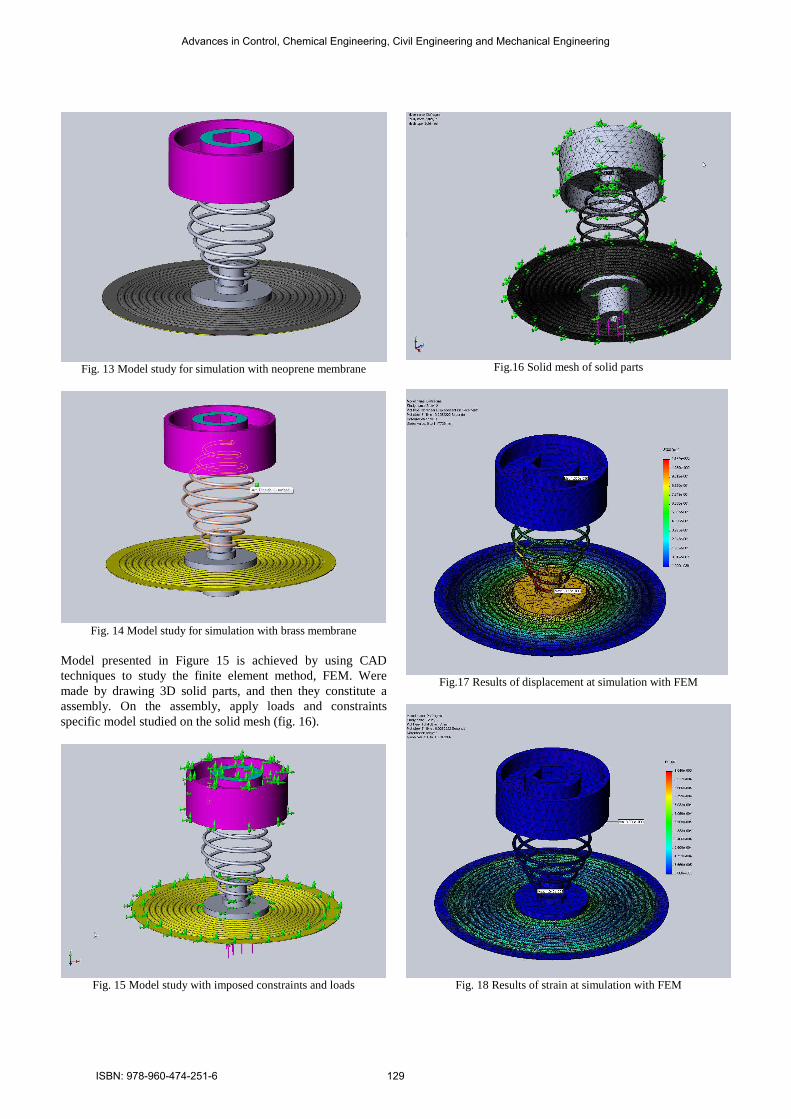
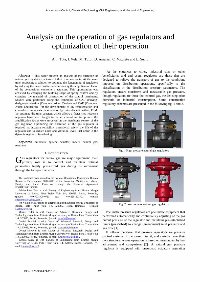
Fig. 13 Model study for simulation with neoprene membrane
Fig. 14 Model study for simulation with brass membrane
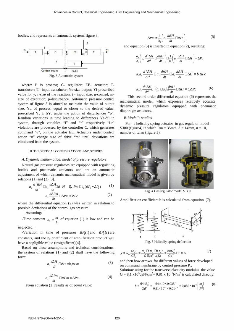
Model presented in Figure 15 is achieved by using CAD techniques to study the finite element method, FEM. Were made by drawing 3D solid parts, and then they constitute a assembly. On the assembly, apply loads and constraints specific model studied on the solid mesh (fig. 16).
Fig. 15 Model study with imposed constraints and loads
Fig.16 Solid mesh of solid parts
Fig.17 Results of displacement at simulation with FEM
Fig. 18 Results of strain at simulation with FEM
Advances in Control, Chemical Engineering, Civil Engineering and Mechanical Engineering
ISBN: 978-960-474-251-6 129

Fig. 19 Results of stress at simulation with FEM
Figure 17, 18, 19 and 20 shows stress, strain, displacement and the stress-strain diagram for the simulation performed for rubber membrane, and in Table 1 shows the numerical results of stress, strain and displacement for the same simulation. The values obtained confirm the experimentally determined values and validate the study model chosen.
TABLE I RESULTS FOR SIMULATION WITH FEM FOR RUBBER MATERIAL
Name Step
Min
[N/mm2]
Location
X,Y,Z
[mm]
Max
[N/mm2]
Location
X,Y,Z
[mm]
Str
ess
VO
N M
ISE
S
Step No: 5(0.0252222Sec)
3.97656e-010
Node: 15467
-146.43
-21.476
-95.308
4.77
at
Node: 6922
7.763
71.504
54.578
Dis
plac
emen
t UR
ES
Step No: 5(0.0252222Sec)
0
Node: 2
17.337
170
2.382
1.17
at
Node: 1
-17.191
0.967
-15.533
Str
ain
ES
TR
N
Step No: 5(0.0252222Sec)
0
Element: 31445
-33.570
139.609
75.503
0.0010
at
Element: 96164
38.782
-19.521
-39.732
Fig. 20 Stress-strain curve for rubber membrane
III. CONCLUSION
Optimizing the natural gas pressure regulator is required to: 1. Increasing the range of pressures, input / output of the regulators; 2. Reducing noise and vibration encountered during operation; 3. Increased operating temperature range; 4. Increased reliability and uptime. All these goals can be achieved by using modern techniques specialists in the field of CAD, CAE, and CAM (Computer Aided Manufacturing). Using these techniques reduce the time required drawing and / or design and actively contribute to the rapid optimization of mechanical parts, constituting the pressure regulator. Studies made by the authors, were based on SolidWorks 2008 software suite, which enables rapid drawing-design-optimization, static and dynamic analysis of complex mechanisms can correct sizing of mechanical parts by finite element simulation. Research and future studies will focus on creating experimental measurements on test stands of the pressure regulators which contain springs and modified membranes, according to these studies to validate experimentally of the theoretical models presented in this paper of their own. Also, it plans to continue studies to develop new models of coil springs and control membranes for gas pressure regulators, continue to optimize them.
REFERENCES
[1] Berce P., Ancau M., Caizar C., Balc N., Comsa S., Jidav H. (2000). Rapid prototyping manufacturing, Technical Publishing House, Bucharest
[2] Canau S. (2009). FEM analysis of spur gear systems with misalignment, Proceedings of DAAAM 2009, Katalinic, B. (Ed.), pp. 261-262, ISSN: 1726-9679, Austria, November 2009, Vienna
[3] Patrascu G., Carutasu N.L., Dragomirescu C.G. (2009). 3D tool wear simulation for turning process, Proceedings of DAAAM 2009, Katalinic, B. (Ed.), pp. 663-664, ISSN: 1726-9679, Austria, November 2009, Vienna
[4] Vintil ă Şt., Cruceru T., Onciu L., Plumbing and gas installations, Didactic and Pedagogic Publishing House, Bucharest, 1995
[5] * HTML.htm http://www.solidworks.com/sw/support/808_ENU_ [6] * HTML.htm, SolidWorks Simulation Professional Accessed on: 2010-
09-10
Advances in Control, Chemical Engineering, Civil Engineering and Mechanical Engineering
ISBN: 978-960-474-251-6 130