analysis of systematic errors in rotating-analyzer ellipsometers
TRANSCRIPT
JOURNAL OF THE OPTICAL SOCIETY OF AMERICA
Analysis of systematic errors in rotating-analyzer ellipsometers*
R. M. A. Azzam and N. M. BasharaElectrical Materials Laboratory, Engineering Research Center, University of Nebraska, Lincoln, Nebraska 68508
(Received 22 April 1974)
The effects of generalized component imperfections, azimuth-angle errors, and errors of the normalizedFourier coefficients of the detected photoelectric current on the measured ratio of reflection coefficients pin rotating-analyzer ellipsometers (RAE) are determined. The problem is formulated in such a way thatmuch of the earlier work done on error analysis for null ellipsometers (NE) can be adapted to RAE. Theresults are conveniently expressed in terms of coupling coefficients that determine the extent to which agiven source of error couples to an error of the measured value of p. The optical properties of thecompensator (if used) and of the surface can be simultaneously obtained from a set of two measurementsusing RAE, in a manner similar to two-zone measurements in NE. In addition, novel methods of obtainingand combining the results from two measurements are examined, with the objective of cancelling the effectof many of the systematic sources of errors. One such method employs two incident polarizations of thesame ellipticity but with orthogonal azimuths, in which case the measured value of p is almost independentof the input optics. If the two incident polarizations are chosen, instead, to have equal but oppositeellipticity and azimuth, the effects of the polarizer imperfection, off-diagonal elements in the compensator,entrance-window, surface, and exit-window imperfection matrices, as well as polarizer and compensatorazimuth-angle ,errors, all disappear upon such two-measurement averaging; the effects of analyzerimperfection or azimuth-angle error and errors of the normalized Fourier coefficients are only partiallycancelled. Finally, use of RAE in generalized ellipsometry and its attendant problems are examined.
Index Headings: Ellipsometry; Polarization; Reflection; Optical systems.
The possibility of detecting the state of polarization of alight beam by Fourier analysis of irradiance variationsbehind a rotating optical analyzer in the beam has beenrecognized.'-5 The method is analogous to one used tomeasure the polarization of lower-frequency electro-magnetic waves by recording the power received by asmall linearly polarized antenna rotated in a planenormal to the direction of wave propagation.6
Recently, several ellipsometer- systems have beendescribed7 -"2 that employ rotating analyzers to measurethe state of polarization of light after its interaction(reflection) with (from) an optical system (surface).These rotating-analyzer ellipsometers (RAE) areattractive because of their speed and precision, andbecause they lend themselves to automation and on-linedata analysis. These considerations are important, forexample, in following rapid surface reactions, in spectro-scopic ellipsometry," and in real-time measurementsduring a manufacturing process.12 To extract informa-tion on polarization from the photoelectric currentdetected after a rotating analyzer, both analog7 -10 anddigital"1"2 signal-processing techniques have beenutilized. The latter generally have improved preci-sion and allow easy combination of the ellipsometerwith a minicomputer, for complicated, on-line datareduction."" 2
As with any measuring instrument, detailed analysesof precision and accuracy are also essential for rotating-analyzer ellipsometers. Hauge and Dill"2 consideredboth precision. and accuracy of RAE, which they callETA, for ellipsometer thickness analyzer. Aspnesexamined the optimization of precision" for threedifferent limiting cases of noise behavior in RAEsystems, and also studied the effect of component
optical activity on calibration and data analysis14 forthe PSA (polarizer-surface-analyzer) and the PCSA(polarizer - compensator - surface - analyzer) arrange-ments of the RAE.
The purpose of the present paper is to analyze theeffects of generalized component imperfections and ofazimuth-angle errors on measurement of the ratio ofthe complex amplitude-reflection coefficients of asurface for the p and s polarizations by use of a rotating-analyzer ellipsometer. The problem is formulated insuch a way that much of the earlier work on erroranalysis for null ellipsometers (NE) can be adapted toRAE. We also consider the simultaneous measurementof the optical properties of the reflecting surface and ofthe compensator, suggest novel ways of carrying outtwo-measurement averaging in RAE (in a manner thatcan be readily automated), and give some attentionto the Kent and Lawson' version of the RAE, becauseof its precision and accuracy. Finally, we examine theuse of RAE in generalized ellipsometry.
I. ERROR ANALYSIS
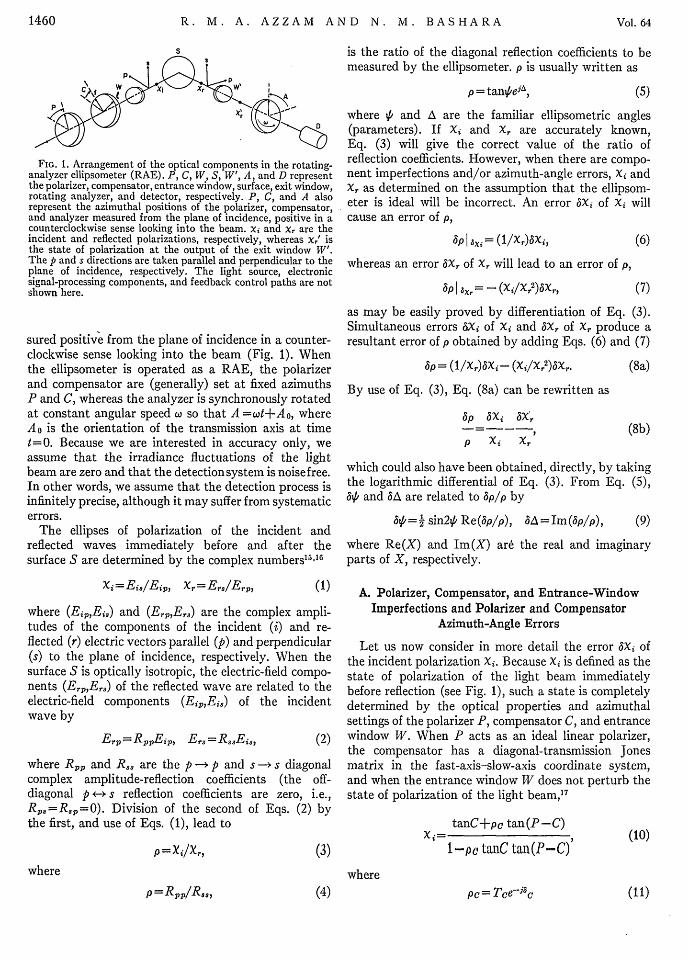
Consider the PCWSW'AD ellipsometer arrangement(Fig. 1). in which the specimen (surface) S undermeasurement is mounted in a test cell with entrance andexit windows W and W', respectively. The polarizingsection (arm) of the instrument consists of a linearpolarizer P and a compensator C, whereas its analyzingsection (arm) consists of a linear analyzer A followed bya photoelectric detector D. P, C, and A also representthe azimuth angles of the transmission axis of thepolarizer, the fast axis of the compensator, and thetransmission axis of the analyzer, respectively, mea-
1459
NOVEMBER 1974VOLUME 64, NUMBER 11
R. M. A. AZZAM AND N. M. BASHARA
is the ratio of the diagonal reflection coefficients to bemeasured by the ellipsometer. p is usually written as
w
XI
FIG. 1. Arrangement of the optical components in the rotating-analyzer ellipsometer (RAE). P, C, W, S, W', A, and D representthe polarizer, compensator, entrance window, surface, exit window,rotating analyzer, and detector, respectively. P, C, and A alsorepresent the azimuthal positions of the polarizer, compensator,and analyzer measured from the plane of incidence, positive in acounterclockwise sense looking into the beam. xi and x, are theincident and reflected polarizations, respectively, whereas x' isthe state of polarization at the output of the exit window W'.The p and s directions are taken parallel and perpendicular to theplane of incidence, respectively. The light source, electronicsignal-processing components, and feedback control paths are notshown here.
sured positive from the plane of incidence in a counter-clockwise sense looking into the beam (Fig. 1). Whenthe ellipsometer is operated as a RAE, the polarizerand compensator are (generally) set at fixed azimuthsP and C, whereas the analyzer is synchronously rotatedat constant angular speed X so that A =wt+Ao, whereAo is the orientation of the transmission axis at timet=0. Because we are interested in accuracy only, weassume that the irradiance fluctuations of the lightbeam are zero and that the detection system is noisefree.In other words, we assume that the detection process isinfinitely precise, although it may suffer from systematicerrors.
The ellipses of polarization of the incident andreflected waves immediately before and after thesurface S are determined by the complex numbers"5 "6
Xi= Ei./Ei ,, x, =Er/Erpa (1)
where (Ei,,Eis,) and (ErpErs) are the complex ampli-tudes of the components of the incident (i) and re-flected (r) electric vectors parallel (p) and perpendicular(s) to the plane of incidence, respectively. When thesurface S is optically isotropic, the electric-field compo-nents (EpErs) of the reflected wave are related to theelectric-field components (Eip,Ei,) of the incidentwave by
Erp= RppEip, Er3 = R 3sEis, (2)
where Rp and R,, are the p -o p and s -n s diagonalcomplex amplitude-reflection coefficients (the off-diagonal p *-. s reflection coefficients are zero, i.e.,Rp,=R3P=O). Division of the second of Eqs. (2) bythe first, and use of Eqs. (1), lead to
p = X/Xr, (3)
where
p= taneJA, (5)
where ,6 and A are the familiar ellipsometric angles(parameters). If Xi and X, are accurately known,Eq. (3) will give the correct value of the ratio ofreflection coefficients. However, when there are compo-nent imperfections and/or azimuth-angle errors, Xi andXr as determined on the assumption that the ellipsom-eter is ideal will be incorrect. An error MXi of Xi willcause an error of p,
ap I axi = (IIX,)6xi,
whereas an error 6X, of Xr will lead to an error of p,
aP I Xr = - (XilXr 2 )bXr,
(6)
(7)
as may be easily proved by differentiation of Eq. (3).Simultaneous errors 6Xi of Xi and 6X, of Xr produce aresultant error of p obtained by adding Eqs. (6) and (7)
ap = (1/X)aXi- (Xi/xr )aXr.
By use of Eq. (3), Eq. (8a) can be rewritten as
ap aXi ax,.
p Xi X,
(8a)
(8b)
which could also have been obtained, directly, by takingthe logarithmic differential of Eq. (3). From Eq. (5),&P6 and SA are related to ap/p by
ASK= sin2iP Re(bp/p), aA =Im(bp/p), (9)
where Re(X) and Im(X) are the real and imaginaryparts of X, respectively.
A. Polarizer, Compensator, and Entrance-WindowImperfections and Polarizer and Compensator
Azimuth-Angle Errors
Let us now consider in more detail the error 6xX ofthe incident polarization xi. Because xi is defined as thestate of polarization of the light beam immediatelybefore reflection (see Fig. 1), such a state is completelydetermined by the optical properties and azimuthalsettings of the polarizer P, compensator C, and entrancewindow W. When P acts as an ideal linear polarizer,the compensator has a diagonal-transmission Jonesmatrix in the fast-axis-slow-axis coordinate system,and when the entrance window W does not perturb thestate of polarization of the light beam,'7
tanC+pc tan(P-C)Xi= I
l-pe~ tanC tan(P-C)(10)
wherep(4= pTce-jc (11)
1460 Vol. 64
p =RppIR8s, (4)
November1974 ERRORS IN ROTATING-ANALYZER ELLIPSOMETERS
represents the slow-to-fast relative amplitude trans-mittance of the compensator; Tc and 3c are therelative amplitude attenuation and phase retardation,respectively.
An imperfect polarizer will be assumed to transmit avibration with small ellipticity. (As pointed out byAspnes, this could be the result of optical activity, as incrystal-quartz Rochon prisms."4 ) In the transmission-axis-extinction-axis coordinate system of the polarizer,such vibration can be described' 8 '9 by the small complexpolarization number d3pp, where 13ppl<<1. Because ofapp, Xi as obtained by Eq. (10) is in error by
6Xi = apipp (12)
to first order, where ap is a complex coefficient thatrelates 6pp to Kxi. The corresponding error Sp of theratio of reflection coefficients p is obtained by substitut-ing Eq. (12) into Eq. (6)
SpI ae= (ap/Xr)3pp
or
pI a PP=YPSiPP, (13)
where
,yp = ap/Xr. (14)
From Eq. (13), we see that -yp defines a complex cou-pling coefficient that couples the polarizer-imperfectionparameter 6pp to an error tip of p. An imperfect compen-sator C or entrance window W is modeled by assumingthat its Jones matrix can be written in the form
T= To+iT, (15)
where T0 describes the ideal behavior of either elementand ST its imperfection properties.2 0 The 2X2 compleximperfection matrix AT= (aiTz) of either C or Wproduces an error e5xi of the incident polarization Xithat can be written, to first order, as
SXi=. aijSTij, (16)ii
where (aij) is a 2X2 array of complex coefficients thatdefines the relationship between aT and t3xi. Substitutionof Eq. (16) into Eq. (6) gives
It is important to observe that, up to this point, thedevelopment, including Eqs. (1)-(18), is the samewhether the instrument is operated as a null ellipsometer(NE), in which case P, C, and A are adjusted for zerodetected light flux, or as a rotating-analyzer ellipsometer(RAE), in which case P and C are set, A is rotated,and the detected light flux is Fourier analyzed. This issignificant because, conseuqently, many of the earlierresults on error analysis for NE can be applied to RAE.
In NE, Xr represents a linear vibration that isdetected by being crossed (extinguished) by the linearanalyzer A; thus
X,= -cotA. (19)
If we substitute this into Eqs. (14) and (18), we obtain
yp(NE)= (-tanA)ap for P, (20)
Yij(NE) = (-tanA)aij for C and W. (21)
In a RAE, Xr represents any linear, circular, orelliptical vibration that is detected by Fourier analysisof the flux variations behind the synchronously rotatinglinear analyzer A.
The coefficients ap and aij, which relate the imperfec-tions dpp and aT to an error axi of the incident polariza-tion Xi according to Eqs. (12) and (16), are indepen-dent of the mode of operation of the ellipsometer.Therefore, we can obtain their values, assuming thatthe instrument is operated as a NE, from Eqs. (20)and (21) as
ap= (-cotA)yp(NE) for P, (22)
aij= (-cotA)-yij(NE) for C and W. (23)
Substitution of ap from Eq. (22) into Eq. (14), and ofaij from Eq. (23) into Eq. (18), yields
-yP(RAE) = (-cotA/X,)yp(NE) for P, (24)
'Yij(RAE) = (-cotA/X)yij(NE) for C and W. (25)
Coupling of the polarizer or compensator azimuth-angle errors (SP or SC) into an error of Xi, hence of p,can be treated in a way exactly analogous to thecoupling of component imperfections. Therefore, theequations that correspond to Eq. (24) or (25) foraximuth-angle errors can be directly written as
zipI |T= (1/Xe) E aijbTijii
tip I T = E yij63 Ti j,iy
where
Equation (17)coefficients p
either C or Wcoefficients (by
,yj= aij/Xr.
gives the error Sp of the ratio of reflexdue to the imperfection matrix a'in terms of an array of complex coul
iiX) -
_yz'(RAE) =(-cotA/X,),yz'(NE), Z=P or C. (26)
-yz' represents a coupling coefficient that relates anazimuth error &Z(==iP or 6C) to an error dip of the ratio
(17) of reflection coefficients according to
P I 5z=yz'a5Z, Z=P or C.
(18) Equations (24)-(26) lead to the important conclusionthat the coupling coefficients that determine the effect
-tion of polarizer, compensator, and entrance-window imper-i of fections, and those that determine the effect of polarizer?ling and compensator azimuth-angle errors in rotating-
analyzer ellipsometers can be obtained by multiplica-
or
(27)
1461
R. M. A. AZZAM AND N. M. BASHARA
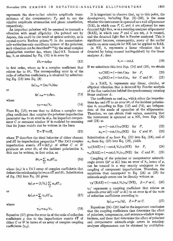
TABLE I. Coupling coefficients for component imperfections in RAE.,
Polarizer (P) Compensator (C) Entrance window (W)(.yij)c, i,j=f,l ('Yij)w, i,j=p,s
Q\ [-pc tan(P-C) -Pc tan2(P-C) -P pxjPC(Q/x,)seC2(P-C) -l
Xr 1tan (P-C) I /x P
Surfaceb (S) Exit window (W') Analyzer (A)('Yij)S, i j= p's ('Yij)W re ,J= p's YA,
* -xil rP -Xil (1arPN /i~x\ tax,- /xr * /Xr p I do ad3 p
Q=sec 2 C/[1-pC tanC tan(P-C)]J, xi=[tanC+pc tan(P-C)]/[1-pc tanC tan(P-C)],Xr= [aj(l-oa 2 -13')}]/(1+8), (OXr/c~a) =- (+ar)'{13Aj[aY(c+1) (1-a'-,i3')4+ (1-ay-j')*]},
(aXr/as) = (1+a!)-I[Fj13(1- c2 -32 )-3]
a These coefficients determine the extent to which small component imperfections app, aTz (Z= C, W, S, W'), SPA of the polarizer P,compensator C, entrance window W, surface S, exit window W', and analyzer A, respectively, couple into errors of the ratio p of thep -- p and s -) s complex reflection coefficients of a surface S in a PCWSW'A rotating-analyzer ellipsometer (RAE) according to5p=-yz~pz (Z=P,A) and Sp =ij Eyzi8Tzxj (Z= C, W, S, W') [Eqs. (13), (17)]. xi and xr define the states of polarization of the lightbeam incident on and reflected from the surface S, respectively [Eq. (1)]. P, C are the azimuth angles of the polarizer and compensator;pc is the slow(l) to fast(f) complex relative transmittance of the compensator; and a, 3 are the normalized Fourier coefficients of thephotoelectric current detected after the rotating analyzer [Eq. (44)]. In case no compensator is used (i.e., in the PWSW'A ellipsometerarrangement), set C=0, pc= 1. Furthermore, if the substitution Xr= -cotA is made, the coupling coefficients for component imperfec-tions appropriate to a null ellipsometer are obtained, where (P, C, A) represents a set of nulling angles.
bBecause it is the ratio of the diagonal elements of the reflection matrix that is measured by the ellipsometer, the elements in the(1,1) and (2,2) diagonal-array positions are of no significance.
tion of the corresponding coupling coefficients pre-viously derived for null ellipsometers'l8 2 021 by the factor-cotA/X,. A summary of the coupling coefficientsthat determine the effect of component imperfectionsand azimuth-angle errors in rotating-analyzer ellipsom-eters is given in Tables I and II.
B. Surface and Exit-Window Imperfections
Often, a reflecting surface is improperly modeled asoptically isotropic, whereas, in reality, it exhibits weakspurious anisotropy caused, for example, by preferential-direction surface roughness, optical activity, or strain.Thus, the reflection matrix R in the ps coordinatesystem is no longer diagonal; rather it has smallnonvanishing off-diagonal elements RS and R,, such
that
1 -<Ki.RP3 Rsp
(28)
We are interested in estimating the error of the calcula-tion of the ratio p(=RI/R,,) of the diagonal reflectioncoefficients due to the presence of the small off-diagonalelements Rp, and R.p.
When the reflection matrix is nondiagonal, therelationship between the incident and reflected polar-izations xi and X, becomes bilinear,' 6
(29)
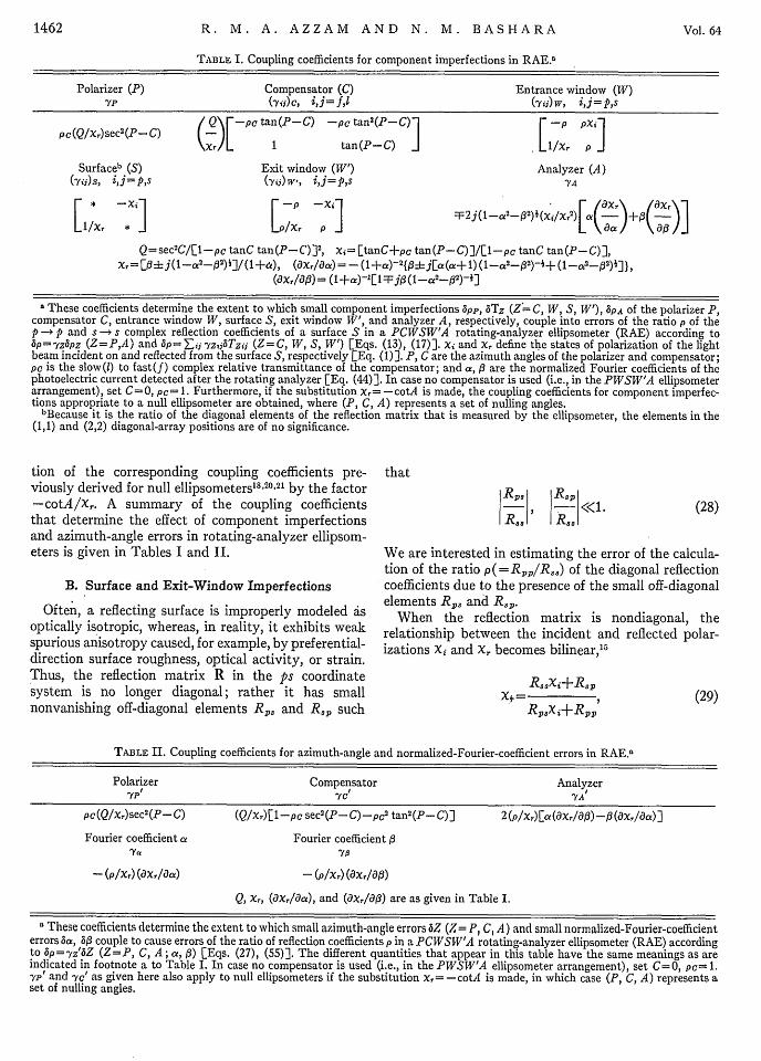
TABLE II. Coupling coefficients for azimuth-angle and normalized-Fourier-coefficient errors in RAE."
Polarizer Compensator Analyzer'YP 'yeI YA/
PC(Q/xr)sec' (P-C) (Q/xr)[1-pc sec2 (P-C)-pc' tan2 (P-C)] 2 (p/xr)[a(oxr/a03)-i3(axr/Oa)]
Fourier coefficient a Fourier coefficient 13
-(p/Xr) (axr/Oa) -(p/Xr) (aXr/0j3)
Q, x,, (ax,/18a), and (axr/al3) are as given in Table I.
a These coefficients determine the extent to which small azimuth-angle errors bZ (Z= P, C, A) and small normalized-Fourier-coefficienterrors Sa, 6,3 couple to cause errors of the ratio of reflection coefficients p in a PCWSW'A rotating-analyzer ellipsometer (RAE) accordingto 3p=yz'SZ (Z=P, C, A; ca, A) [Eqs. (27), (55)]. The different quantities that appear in this table have the same meanings as areindicated in footnote a to Table I. In case no compensator is used (i.e., in the PWSW'A ellipsometer arrangement), set C=0, pc= 1.-yp' and -yc' as given here also apply to null ellipsometers if the substitution x= -cotA is made, in which case (P, C, A) represents aset of nulling angles.
1462 Vol. 64
R8sxi+R8pX.�= 7
Rpsxi+Rpp
November1974 ERRORS IN ROTATING-ANALYZER ELLIPSOMETERS
which reduces to Eq. (3) when Rps=R,= 0. By takingthe inverse of Eq. (29), we obtain
Rppxr-RspXi=
-RpaXr+Ras
( /Rp2 R, p
1?,, RsI RPt ciXi = 1--Xr
If the condition
than Xr, is detected by the analyzer A; the perturbationXr'-Xr is generally small. If we represent the exitwindow by a Jones matrix Tw, in the ps coordinatesystem, the relationship between Xr' and Xr can beexpressed in exactly the same way as the relationshipbetween Xr and xi in Eq. (29). Because Tw, is slightlydifferent from the 2X2 identity matrix, it is approx-imately diagonal. Thus, all of Eqs. (29)-(32) areapplicable in the present case if the substitutions
Xi xr, X, -* XI' and R -Tw are made. In particular,Eq. (32) now reads
(31) X /T= T(siX'+TWP(X')2()
is satisfied,2 2 the first factor on the right-hand sideof Eq. (30) can be replaced by its linear binomialexpansion,
Rp \RPP RspXi = 1+-XI -Xl x--
Ras/ \Ras Ras/
(32)
to first order in the quantities limited by the in-,equalities (28) and (31). Equation (32) can be solvedfor p =RI/R,, to give
(33)
by use of the fact that p = X/lx,, Eq. (3), to zero order.From Eq. (33), we see that the errors of the ratio of
the diagonal reflection coefficients p = R~p/RSS caused bythe neglect of existing small off-diagonal elements Rpsand RP in the reflection matrix R are
AP I RP. =-Xi() SP I R8p= R) (34)
RpS/R3S and RBp/RSS can be considered as surface-imperfection parameters; their effects on p can beevaluated by coupling coefficients IYp and Pysi such that
SP I Rp, =7/SR) a3 SPR~p=Y3P(R) (35)
by analogy with Eq. (13). Comparison between Eqs.(34) and (35) shows that
ps -X, ysp = 1/X7, (36)
which are also cited in Table I.To examine the effect of the exit window W', let us
assume that it changes the state of polarization of thelight beam from XI to Xr', Fig. 1. Note that XI', rather
Twi's)'(37)
where Tw'ij (i,j=p,s) are the elements of the exitwindow's Jones matrix Tw, in the ps coordinate system.If we write Tw=TwA+6Tw, [Eq. (15)], Eq. (37)can be put in the form
Xr=Xr'+Xr(tTwpp-&Twtss)+Xr 2 Tw'ps-a3Tw's3p (38)
where bTw'ij (ij=p,s) are the elements of the exit-window imperfection matrix &Tw,. In going fromEq. (37) to Eq. (38) use has been made of the factthat Xr'Z-Xr and that Tw°O equals the 2X2 identitymatrix if a constant multiplicative factor is neglected.The first term of Eq. (38) represents the zeroth-orderapproximation to XI, and the second term
3Xr= Xr(3Tw'pp-bTwa3) +XA26Tw', p-e5Twap, (39)
represents a first-order correction that is needed toaccount for the effect of the exit-window imperfectionATEw. The error of the ratio of reflection coefficients 5pcaused by bTw, is obtained by substituting from Eq.(39) into Eq. (7)
aPI 5Tt = - (Xi/X,) (6Tw pp-6Tw'ss)- (Xi)bTw,,ps+ (Xi/Xr 2) STw,,p
or
P I 5Tw = -p(6Tw pp-6Tw'8 8 )-Xi6iTw pa+ (p/Xr)STwap, (40)
if the substitution p=Xi/X, is made. Equation (40)takes the form of Eq. (17), from which the array ofcoupling coefficients (yir) w' (i, j= p,s) that relates aT wto an error ap is determined. Such an array is given inTable I.
The foregoing analysis of the effect of surface andexit-window imperfections is valid irrespective of themethod by which X, is analyzed. In other words, theresults are valid for both null and rotating-analyzerellipsometers. In the former, X, represents a linearvibration that is detected by the crossed analyzer Aand is given by Xr= -cotA, Eq. (19). In the latter, X,
Rp«_X I<< 1
RJJ
1463
Xi- Rps 1 RapP=- Xi - +_ -XI Rs.? XI Ras
Rpp� RPP R RXi= - XI+ X I2 -3_0
Ras ) Ras Ras Ras '

R. M. A. AZZAM AND N. M. BASHARA
is arbitrary and is determined by the Fourier analysisof the photoelectric current detected behind the rotatinganalyzer A, as will be discussed in the next section.
C. Analyzer/Detection System Imperfectionsand Analyzer Azimuth-Angle Error
Let XA O represent the polarization passed by theanalyzer A at some reference-azimuth setting aroundthe beam axis. For generality, XAO is assumed to bearbitrary, so that the analyzer may act as an ellipticalanalyzer. When the analyzer is rotated from its referenceposition by an angle A in a counterclockwise senselooking into the beam, the transmitted polarization XA
in this new (oblique) orientation is related to XAO by
(cosA)XAo+ (sinA)XA=
(-sinA)XAO+ (cosA)
or
tanA+XAoXA= , (41)
1 -tanAXAo
which is a bilinear transformation that expresses theeffect of the rotation A.' 5
If Ir denotes the irradiance of the reflected beam thatis polarized in the state X,, the proportion ID of I,passed by the analyzer A and detected by the photo-detector D is a function of X, and XA given by23
XFXr*XAXA*+XrXA*+Xr*XA+ 1ID =klI
XTXr*XAXA*+XrXr*+XAXA*+1
and
(1- IXl2)(1-| XA 01 2) +4 Re (Xr) Re (XA O)a =
(1+ lX,| 2)(1+ I XAQ I2)+4 Im(X,) IMr(XAo)'
2 Re (Xr) (1- IXA o12)-2 Re(XAo)(1- IXr 12)
(1+1X,12)(1+1 XAO 12)+4 Im(x,) Im(XAO)
(46a)
(46b)
In Eq. (44), I represents the average transmittedirradiance over one full rotation of the analyzer; a and 3represent the normalized cosine and sine Fourier coeffi-cients of the irradiance function ID (A). In Eqs. (45)and (46), X I, Re(X), and Im(X) denote the absolutevalue, real, and imaginary parts of the complex polar-ization number X, respectively. As a simple check onEqs. (46), note that a =, =0 when X = 4 j (i.e., whenthe reflected polarization is circular), and also whenXAO = -4j (i.e., when the analyzer acts as a circularanalyzer), as expected. Also, Eqs. (46) are symmetricalwith respect to X, and XAO, as they should be.
By solving Eqs. (46a) and (46b), X, can be recon-structed in terms of the normalized Fourier coefficientsa and 3 as well as the polarization state XA o transmittedby the analyzer in its reference position.26 When ananalyzer of known XAO is synchronously rotated atconstant speed, a and ,B can be measured by analog ordigital Fourier analysis of the periodic photodetectorcurrent from which X, can be determined.
Now consider the special case when the analyzer islinear, as often it is. If we take the reference positionof the analyzer to be that in which its transmissionaxis is parallel to the plane of incidence, then
where the superscript asterisk indicates the complexconjugate and k represents the transmittance of theanalyzer when Xr=XA.
In a null ellipsometer (NE), Xr and (or) XA areadjusted2 4 until ID=O. From Eq. (42), this conditionis satisfied when
Xr =- l/XA*, (43)
which means that the reflected polarization X, must beorthogonal25 to the polarization admitted by theanalyzer A.
In a rotating-analyzer ellipsometer (RAE), X, isdetermined from the variation with azimuth of theirradiance ID leaving the rotating analyzer A. Therefore,we need to examine ID as a function of the analyzerazimuth angle A, which can be done by substituting XA
from Eq. (41) into Eq. (42). After some manipulations,this substitution leads to
ID=I[I+a cos2A+3 sin2A], (44)
where
I(1+IXrI2)(1+ JXAo12)+4 Im(X,) Im(XAO)
I =kIr- (1+1Xr12)(1±+XAO 12) -
(45)
XAO=O-
Substitution of XA O = 0 into Eqs. (46a) andsimplifies them considerably
(1- IXrI2)
(1+ IXr I2)
2 Re(X,)1= -
(1 + | Xr |12)
Equations (48a) and (48b) can beand Re(Xr) in terms of a and 3
1-a3X, I = l,+cJ '
Re(X,) = -(1+a)
(47)
(46b)
(48a)
(48b)
solved for I X, I
(49a)
(49b)
From I XI and Re(X,), the state of polarization of thereflected light beam Xr is given by the identity
X,=Re(X,)4j( I XrJ2-[Re(Xr)]2}* (50)
1464 Vol. 64
I

November 1974 ERRORS IN ROTATING ANALYZER ELLIPSOMETERS
where1
(1 +a)(51)
if Eqs. (49a) and (49b) are used.Equations (50) and (51) show that two reflected
polarizations X, and xr* lead to the same normalizedFourier coefficients a and 3. If (0rer) represent theazimuth and ellipticity angle of X,, then27 (r, - Er)will be the azimuth and ellipticity angle of xr*. There-fore, the handedness (sign of the ellipticity) of thereflected polarization is indeterminate in a polarization-detection technique that employs a rotating linear28
analyzer as is intuitively expected.'2 -'4 When thereflected polarization X, is given by the normalizedFourier coefficients a and f, Eq. (51), and the incidentpolarization Xi is determined from the fixed azimuthalsettings of the polarizer and compensator. Eq. (10),the ratio of reflection coefficients p as measured by theRAE is
RAE=(1 +a)PI RAE=
[ijl-a2-2*tanC+pc tan(P-C)
X1-p.c tanC tan(P-C)
(52)
In Eq. (52), P and C are the polarizer and compensa-tor azimuth angles; PC is the slow-to-fast complexrelative transmittance of the compensator, as before.
Systematic errors 5a and 63 of the normalized Fouriercoefficients a and 13 may be caused by analyzer imperfec-tions, analyzer azimuth-angle errors, or by errors inthe photoelectronic detection system. They will lead tocorresponding errors of Xr,
a xrz) ax,)
/Xi a/Xr\
kXr2A )a
1465
(56a)
(56b)
define coupling coefficients relating 3a and 3h to anerror ep of p.
To determine the effect of a small analyzer imperfec-tion, we need only determine doa and 651 that arise fromsuch an imperfection. As with the polarizer, theanalyzer may be imperfect, in that it transmits avibration that is slightly elliptical instead of exactlylinear so that
XAO=6PA, I 3PA 1<<1. (57)
When the reference position of the analyzer is such thatthe major axis of the almost-linear elliptical vibrationdescribed by Eq. (57) is parallel to the plane of in-cidence, 3
PA is a pure imaginary number. SubstitutingEq. (57) into Eqs. (46), and noting Re(XAo)=O bythe above choice of the analyzer reference position,we find that
ba= [j2a(1 -a 2-02)] (SPA),
a: = i [Dj23 ( 1-a2 -,2) i] (SPA)
(58a)
(58b)
to first order in the imperfection parameter 3PA.
Therefore, the small analyzer imperfection 6 PA leads toan error ep of the measured ratio of reflection coefficientsp in RAE systems given by tP I apA=YA(6PA), where
YA = F2j(1 _a2_02) (Xi/Xr2)[a(_)±+( )]l (59)
/ 1Xr\e5Xr=t /a
/ i3Xr\ax, = ( a:
From Eq. (51), we get
aXr -1
aa { ((+a(2
+ (1-1a2'-#2)i]},
OXr 1-= [1Fji3(1-a2_02)-].013 (I +q)
(53a) is the analyzer-imperfection coupling coefficient. Equa-tion (59) is readily obtained by combining Eqs. (55),(56), and (58).
(53b) The errors of the normalized Fourier coefficients baand a3 caused by an analyzer azimuth-angle error SAcan be simply derived by replacing A and A +6A inEq. (44). Such a step leads to
(54a)
(54b)
The errors of the ratio of reflection coefficients p due to3a and 613 are obtained by substituting'Eqs. (53) intoEq. (7); the errors can be written as
Spt aa==y8a, (55a)
6p I SO = Y 6a 3 , (55b)
ha= (20)3A,
a:3= (-2a)5A.
From Eqs. (55), (56), and (60), we obtain'YA =(X)L (-) a: -) ( )
which is the coupling coefficient for an analyzer azimuth-angle error relating 5 p to 6A according to 6 p IA =YA5A
[Eq. (27)].The coupling coefficients that have been derived in
, this section are summarized in Tables I and II.
(60a)
(60b)
(61)

R. M. A. AZZAM AND N. M. BASHARA
II. SIMULTANEOUS MEASUREMENT OF THECOMPENSATOR AND SURFACE
OPTICAL PROPERTIES
In Sec. I, we have assumed that the slow-to-fastcomplex relative transmittance pc of the compensatoris known, so that the ratio of p -- p and s -+ s complexreflection coefficients p of the surface S could bedetermined in terms of it. In null ellipsometry, bothPC and p are often measured simultaneously, forexample, by taking data corresponding to the twononequivalent nulls that are available when thecompensator is set at a fixed azimuth (different fromzero, usually ±7r/4) and the polarizer and analyzerare adjusted for null."6 8' 29-34 In this section, we showthat pc and p can also be measured simultaneously byuse of a rotating-analyzer ellipsometer.
From Eqs. (3) and (10), we have"
1 tanC+pc tan(P-C)Pa=-, (6a
x, I-pc tanC tan(P-C) (62a)
which can be solved for Pc to give
1 pXr-tanC (62b)
tan(P-C) 1+pxr tanC
Let us assume that, with the compensator C set at afixed azimuth3 CF0, two measurements of the reflectedpolarization X,1 and X, 2 are made (by analog or digitalFourier analysis of the detected photoelectric currentafter the rotating analyzer) corresponding to twodifferent settings P1 and P2 of the linear polarizer P.If Eq. (62a) is written first in terms of (Pi,Xri), thenin terms of (P2,X,2), and if the results are equated, weget a quadratic equation in pC
p02 ±+rPC+m2 = 0, (63a)
whose solution is
pC _-4m+ (m,2 -4m 2 ) 1, (63b)
ml=2(Xri-x, 2)-' csc(2C)[cot(P 2-C)-cot(P--C)], (63c)
m2 =-cot(Pl-C) cot(P2-C). (63d)
With pc now determined from Eqs. (63), we cansubstitute its value, together with either (Pi,Xrl) or(P 2 ,Xr2 ), into Eq. (62a) to obtain3 7 p.
From the foregoing we conclude that two measure-ments (Pixri) and (P 2 Xr2), taken with the compensatorset at a fixed azimuth C5;0 allow the slow-to-fast com-plex relative transmittance pC of the compensator, andthe ratio of the p -- p and s -* s complex reflection co-efficients p of the surface, to be determined simultane-ously by use of a rotating-analyzer ellipsometer. Note,however, that we implicity assume that X, can beunambiguously distinguished" from xr*. Otherwise,this X, or Xr* ambiguity will propagate to Pc through
Eqs. (63c) and (63b), and may become of concern,unless we know an approximate value for Pc, which isoften the case.
In this two-measurement scheme for the determina-tion of p and Pc, the compensator azimuth C (5O0) andthe polarizer azimuths PI and P2 can all be chosen atwill. For convenience, we may take C=4.r/ 4 andP 2 -Pi=r/2, simulating conditions that are en-countered in two-zone null ellipsometry. In this case,Eqs. (63c) and (63d) simplify considerably
m = 2 (Xrl - Xr2)-' sec2Pi,
m2 = 1.
(63c')
(63d')
Again, P1 remains arbitrary. The situation in two-zonenull ellipsometry would be exactly reproduced if P,is chosen so that Xi represents a linear vibration (henceis real), in which case Xr2 (at P2 =P,+7r/2) would alsorepresent a linear vibration. 3 9
Determination of the ratio of reflection coefficients pfrom any combination of two measurements (P1 ,XD),(P2 ,Xr2 ) in a RAE has the same advantage of thefamiliar two-zone measurements in a NE, in that theeffect of an inexact (or unknown) value of the compensa-tor relative transmittance PC is cancelled. Cancellationof the effect of additional error sources characteristic oftwo-zone averaging18' 21' 34 in NE can also be achieved inRAE if C, P1 , and P2 are chosen to create similarconditions in both arrangements as indicated above.
With the RAE ellipsometer under computer con-trol,"",12 the two-measurement method can be auto-mated. Thus, with the compensator set at a fixedazimuth, one measurement X,. (of X,) is made at apredetermined setting for the polarizer Pi. After thismeasurement of Xri has been completed by averagingover a suitable number of cycles of the photodetectorcurrent, an order signal is sent by the computer torotate the polarizer from P, to P2 either mechanically,by a stepping or servomotor, or electro-optically, by aFaraday cell or a KDP crystal subjected to half-wavevoltage, and X,2 is subsequently measured. The com-puter may then process the data C, (Pi,,ri), (P2,Xr2)according to Eqs. (62) and (63) to determine p and pc.Values of pc for a given compensator need only bemeasured once over a given spectral range of interest,then stored in the computer for subsequent dataanalysis based on one measurement (P,X,) only.
III. GENERAL TWO-MEASUREMENTAVERAGING TECHNIQUES
In the previous section, we have shown how tocombine the results from two measurements (Pi,Xrl)and (P2,X,2) in order to determine the optical propertiesp of the surface and pe of the compensator by use of arotating-analyzer ellipsometer (RAE). We explainedthat the advantage of two-zone averaging in thecancellation of systematic errors in null ellipsometers
1466 Vol. 64
November 1974 ERRORS IN ROTATING-ANALYZER ELLIPSOMETERS
(NE) can also be achieved in RAE if the particularazimuthal relationships at null in the former arereproduced in the latter. Here we consider general waysof averaging the results from two measurements, withthe objective of cancelling the effect of many of thesources of systematic error discussed in detail in Sec. I.
First, consider a pair of measurements (Xi1,Xr1 ) and(Xi 2,Xr 2) obtained from the mapping of two differentincident polarizations Xi1,Xi2 into two corresponding.reflected polarizations Xrl,Xr2. From Eq. (3), twovalues of p are obtained
pi = Xii/Xri, (64)
P2 = Xi2 /Xr 2 ,
whose geometric mean is
p = (XiiXi 2/XriXr 2) . (65)
If the two incident polarizations Xi, and Xi2 are chosensuch that
the output optics (exit window and analyzer) or inthe detection system will affect Xri and X, 2 and hencethe value of p [Eq. (67)].
Now we consider a general approach to two-measure-ment averaging in RAE which is based on the erroranalysis of Sec. I. From Sec. I, the ratio of reflectioncoefficients p, corrected to first order in all imperfectionsand azimuth errors, can be written as
(68)P= (Xi/X,)+57 -Yk(XiXr)3fkb
where Xi and X, are obtained from the instrument data(P, C, pc, a, 3) if we assume that the ellipsometer is idealby substituting such data into Eqs. (10) and (51),respectively. -Yk is a coupling coefficient for a generalsource of error 3fk (be it an azimuth error, componentimperfection, or Fourier-coefficient error) and thesummation over k includes all sources of error cited inTables I and II. In a slightly different form, Eq. (68)can be rewritten as
Xi1Xi2 = -1,
Eq. (65) becomes
p = (-1/xrlXr 2 ) 1 .
(66)
(67)
This result is significant because it shows that the ratioof reflection coefficients p will be independent of theinput polarization optics (polarizer, compensator, andentrance window) if the two incident polarizations Xi1
and Xi2 satisfy Eq. (66). If (0iei) are the azimuth andellipticity angle of xi, then27 (Oi-ir/2, Ei) will be theazimuth and ellipticity angle of (- 1/Xi). Thus Eq. (56)is satisfied if the two incident polarizations Xi1 and Xi2
have the same ellipticity and if their azimuths areexactly orthogonal (7r/2 apart).
This scheme of neasurement can be easily automatedwhen the ellipsometer is under computer control.Assume, first, that no compensator is used. In this case,Xr1 is measured with the polarizer set at some suitable4 0
azimuth Pi. When X'1 has been measured, a signal issent by the computer to rotate the polarizer azimuthby exactly 900, either mechanically or electro-optically,and a second value X,2 is measured. The value of p isobtained from Xr1 and Xr2 by the operation indicated byEq. (67). If precision considerations favor the use of acompensator,12 "3 the first value Xri is measured withthe polarizer and compensator set at azimuths P1 , C1,the second X,2 is measured after both of these elementshave been rotated 900 in the same direction. Thegeometric mean of the results is then obtained by use ofEq. (67). Again, the rotation of the polarizer and of thecompensator can be excuted mechanically or electro-optically.4'
It is important to observe that the accuracy of theabove two-measurement averaging procedure is totallyindependent of the input optics only if the rotation ofthe azimuth of the incident vibration is exactly 90° fromthe first measurement to the second. Imperfections of
p=p 0 (l+(l/p') E 'Yk(XiXr) 6fk),k
(69)
where p0 = (Xi/xr) is the zeroth-order approximation top. If two sets of values (Xi1,Xr1 ) and (Xi 2 ,Xr 2 ) aremeasured, we get from Eq. (68)
p1=pi0 (l+(l/p10 ) E Zk(XibXrl)fAk
P2=P20(l+ (l/p2) E 'Yk(Xi2,X,2)f6fk),k
(70)
where p°O= (Xil/X, 1), P20 (Xi 2 /Xr 2). Taking the geo-metric mean of p1 and P2 of Eqs. (70), and noting thatp10 ~P2l'°-P'(p10P20 )1, we obtain
p= (p' 0p2A)I1+2 (pj~p20) ['Y EYk(Xii,Xri)k
+'Yk(Xi2,X,2)15fk), (71)
to first order.Equation (71) can be considered as the general basis
of all two-measurement averaging methods in conven-tional ellipsometry, irrespective of whether the ellipsom-eter employs null or rotating-analyzer detection tech-niques. The effect of a given source of error bfk iscancelled by two-measurement averaging if
'Yk (XilX,1) +Yk (Xi2,Xr2) = 0or
Yk(Xi2,Xr2) = -Yk(Xil,Xr1)- (72)
The optimum combination of two measurements(XilXr), (Xi2,X, 2) for best accuracy is that whichsatisfies Eq. (72) for the majority of the sources oferror. One very interesting possibility is to make thetwo measurements so that
Xi2 =-Xil, (73)
Xr2 =- X,-
1467
R. M. A. AZZAM AND N. M. BASHARA
Equations (73) are satisfied when
P 2=P, (74)C2=-Cl,
as may be seen from Eqs. (3) and (10). From Eqs. (49),we note also that if a, and 3,B are the normalizedFourier coefficients corresponding to Xr,, then
a2 = a1, (75)
02=-01,
are the normalized Fourier coefficients that correspondto Xr 2 = -Xr. From Table I, and by use of Eqs. (73)and (74), we find that Eq. (72) is satisfied for thecoupling coefficients to the polarizer imperfection andthe off-diagonal elements of the compensator, entrance-window, surface, and exit-window imperfection ma-trices; hence their effect is cancelled by two-measure-ment averaging. From Table II, and by use of Eqs. (74)and (75), we find that Eq. (72) is satisfied for thecoupling coefficients for polarizer and compensatorazimuth-angle errors; hence their effects are alsocancelled by two-measurement averaging. The effectof the remaining imperfection parameters given inTables I and II is either partially cancelled (as with theanalyzer imperfection or azimuth error, and errors ofthe normalized Fourier coefficients) or not cancelledat all.
As a special case of the two-measurement scheme, thevalues of PI, C1 may be chosen so that X1 = +j, whichrepresents the right-circular polarization; in that case,X,2=-j (P 2 = -P 1 , C2 =-C1), which represents theleft-circular polarization. Such circular states can beeasily detected by nulling the ac component (a=,B=O)of the photodetector current, and the scheme becomessimilar to the Kent and Lawson version of the RAE.4 2
The ac null condition can be reached automatically ifthe polarizer and compensator are rotated by steppingor servomotors under control of the detected photo-electric current. Furthermore, because the second nullis simply related to the first, Eq. (74), it can also bereached rapidly. Then the two measurements areaveraged, which results in accurate determination ofthe ratio of reflection coefficients p. This is ensured bycancellation of many of the sources of error, as describedabove. Because of its additional high precision,14 thismode of operation of the ellipsometer should becomemore popular.
IV. USE OF RAE IN GENERALIZEDELLIPSOMETRY
Recently, we have shown that an ordinary ellip-someter operated in the nulling mode can be used tomeasure the normalized noldiagonal Jones matrix ofany linear nondepolarizing optical system, in general,and the normalized nondiagonal reflection matrix ofany optically anisotropic surface, in particular.'7 43
This generalized ellipsometry can also be done by use ofrotating-analyzer ellipsometers (RAE), with or withouta compensator. In fact, most of our previous work isalready formulated in a manner that permits easyextension to RAE. Specifically, the procedure by whichthe normalized Jones matrix of the optical system(surface) under measurement is determined from three(or more) pairs (XiiXr), (Xi2,Xr2), (Xi3,Xr3) of incidentand reflected polarizations is independent of how thereflected polarization Xr is analyzed, either by null orrotating-analyzer (photometric) detection. However,the fact that a reflected polarization state Xr cannot bedistinguished from its complex-conjugate state X,* byrotating-linear-analyzer detection, Eqs. (50) and (51),poses a more-serious problem in generalized ellip-sometry than it does in conventional ellipsometry.This X, or Xr* uncertainty gives rise to eight pos-sible combinations (XrlXr2,Xr3), (Xri*,Xr2,Xr3),(Xri*,Xr2*,Xr3*) of three reflected polarizations that canbe used. Hence, eight possible normalized Jones matricescan be obtained from the mapping of the three incidentpolarizations (xil, Xi2, Xi3) onto each of the eight setsof three reflected polarizations. In case measurementsare made on a system about which some information isavailable, it may be possible to reject immediatelyseven wrong possibilities. Otherwise, the X, or Xr*ambiguity may have to be resolved experimentally12 '14
before RAE can be employed successfully in generalizedellipsometry.
V. SUMMARY
In Sec. I, we analyzed the effect of systematic errorson the measurement of the ratio p of the p -- p ands -* s complex reflection coefficients of a surface S whenrotating-analyzer ellipsometers (RAE) are used. Thesesystematic errors include (1) generalized componentimperfections in all of the elements of the PCWSW'A(polarizer P, compensator C, entrance window W,surface S, exit window W', analyzer A) ellipsometerarrangement, of which the PWSW'A arrangement with-out the compensator C is a special case; (2) polarizer,compensator, and analyzer azimuth-angle errors; and(3) systematic errors of the normalized Fourier coeffi-cients a and j of the detected photoelectric current.Much of the analysis is an adaptation of earlier workdone for null ellipsometry (NE), and the results areconveniently summarized in terms of coupling coeffi-cients in Tables I and II.
In Sec. II, we showed that the optical properties pof the surface, and pc of the compensator (its complexslow-to-fast relative transmittance) can be simul-taneously determined from a set of two measurementsby the RAE. In Sec. III, we examined novel ways ofcombining the results from two measurements in RAEwith the objective of cancelling the effects of systematicerrors studied in Sec. I. Finally, we considered theapplication of RAE to generalized ellipsometry inSec. IV.
1468 Vol. 64

November1974 ERRORS IN ROTATING-ANALYZER ELLIPSOMETERS
ACKNOWLEDGMENT
R. M. A. Azzam would like to acknowledge usefuldiscussions with Dr. D. Aspnes of Bell Laboratoriesconcerning the rotating-analyzer ellipsometer, and tothank him for making available preprints of his paperson this subject.'3 " 4
REFERENCES
*Work supported by the National Science Foundation.'C. V. Kent and J. Lawson, J. Opt. Soc. Am. 27, 117 (1937).2W. Budde, Appl. Opt. 1, 201 (1962).3S. R. Rajagopalan and S. Ramaseshan, Proc. Indian Acad. Sci.
A 60, 297 (1964).4S. R. Rajagopalan and S. Ramaseshan, Proc. Indian Acad. Sci.
A 60, 379 (1964)."D. Clarke and J. F. Grainger, Polarized Light and Optical
Measurement (Pergamon, New York, 1971).6J. I. Bohnert, Proc. IRE 39, 549 (1951).7 B. D. Cahan and R. F. Spainer, Surf. Sci. 16, 166 (1969);
also, in Proceedings of the Symposium on Recent Developments inEllipsometry edited by N. M. Bashara, A. B. Buckman, andA. C. Hall (North-Holland, Amsterdam, 1969).
8R. Greef, Rev. Sci. Instrum. 41, 532 (1970).'J. C. Suits, Rev. Sci. Instrum. 42, 19 (1971).0D. J. Scholtens, J. F. Kleibeuker, and J. Kommandeur, Rev.
Sci. Instrum. 44, 153 (1973)."D. E. Aspnes, Opt. Commun. 8, 222 (1973)."P. S. Hauge and F. H. Dill, IBM J. Res. Dev. 17, 472 (1973)."D. E. Aspnes, J. Opt. Soc. Am. 64, 639 (1974).'4 D. E. Aspnes, J. Opt. Soc. Am. 64, 812 (1974)."R. M. A. Azzam and N. M. Bashara, J. Opt. Soc. Am. 62, 222
(1972).'6 D. A. Holmes and D. E. Feucht, J. Opt. Soc. Am. 57, 466
(1967).'7R. M. A. Azzam and N. M. Bashara, J. Opt. Soc. Am. 62,
336 (1972).'8 R. M. A. Azzam and N. M. Bashara, J. Opt. Soc. Am. 61,
600 (1971).19W. R. Hunter, D. H. Eaton, and C. T. Sah, Surf. Sci. 20, 355
(1970).90R. M. A. Azzam and N. M. Bashara, J. Opt. Soc. Am. 62, 700
(1972). For the compensator, Tc° is diagonal; the ratio of the2,2 to the 1,1 matrix elements is equal to pc [Eq. (11)]. Forthe entrance (and exit) window, Tw° is the product of acomplex constant times the 2X2 identity matrix.
2'R. M. A. Azzam and N. M. Bashara, J. Opt. Soc. Am. 61,773 (1971); J. Opt. Soc. Am. 61, 1236 (1971).
"Notice that, because of the inequality (28), the inequality (31)restricts xr to lie inside, on, or not too far outside the unitcircle I xI I = 1 in the complex plane of polarization. In otherwords, the reflected polarization should be more p-like thans-like.
23R. M. A. Azzam and N. M. Bashara, Appl. Phys. 1, 203(1973); Appl. Phys. 2, 59 (1973).
94Xr is controlled by the optical elements P and C of thepolarizing arm of the ellipsometer, whereas XA is adjusted byrotating the analyzer A around the beam axis, Eq. (41).
"5See Eq. (5), Ref. 15.
1469
26Equations (46a) and (46b) can be simplified, without loss ofgenerality, if we choose the reference position of the analyzerso that the major axis of the transmitted elliptical vibrationXAO is parallel to the plane of incidence. Thus, in this case,XAO is pure imaginary, Re(xAo) = 0, and the second terms inthe numerators of the right-hand sides of Eqs. (46a) and(46b) become zero.
27See Fig. 4 and Table II of Ref. 15.28If an elliptical, instead of linear, analyzer is used, the two
polarizations x, and x,* that differ only in handedness lead todifferent normalized Fourier coefficients a and 3, hence can bedistinguished. This can be seen from Eqs. (46a) and (46b) bynoting that, for an elliptical analyzer, the second terms inthe denominators of the right-hand sides of these equationsare nonzero and switch sign as x,* is substituted instead of x,.
29R. J. Archer and C. V. Shank, J. Opt. Soc. Am. 57, 191 (1967).30T. Yolken, R. Waxler, and J. Kruger, J. Opt. Soc. Am. 57,
283 (1967)."1W. G. Oldham, J. Opt. Soc. Am. 57, 617 (1967).32F. L. McCrackin, J. Opt. Soc. Am. 60, 57 (1970)."3J. A. Johnson and N. M. Bashara, J. Opt. Soc. Am. 60, 221
(1970).'4D. E. Aspnes, J. Opt. Soc. Am. 61, 1077 (1971)."Equation (62) is the same as Eq. (52) except that, in the latter,
x, is explicitly expressed in terms of the normalized Fouriercoefficients a and /3 using Eq. (51).
36When C= 0, Eqs. (62a) and (62b) become identical andequivalent to one equation, p/pc= tanP/xr, and the sub-sequent discussion does not apply.
37Alternatively, starting with Eq. (62b) and repeating stepssimilar to those that led to Eq. (63a), we can obtain aquadratic in p only.
38Ways to achieve this are mentioned in Refs. 12 and 14.39This assumes that I p.c I = Tc is very close to unity, which is
true for most compensators. From Eq. (51), note that x, isreal; hence it represents a linear vibration, if a2+02= 1. Thisleads to an amplitude of the ac component of the photo-electric current equal to its dc component, as may be seenfrom Eq. (44) after the cosine and sine terms are combinedinto a single sine or cosine term. Thus, a linear state can bedetected by a rotating analyzer from the condition ofmaximum (unity) modulation depth in the photoelectriccurrent. See Ref. 14.
4 0This may be chosen on the basis of optimum-precisionconsiderations, as discussed in Refs. 12 and 13.
41 The azimuth of the compensator can be changed 900electronically, e.g., by use of a KDP crystal mounted torotate with the (quarter-wave) compensator as one unit, towhich a half-wave voltage that can be regulated by a correc-tive electro-optic feedback loop is applied along the fast axisof the compensator.
4 2The method of Kent and Lawson (Ref. 1) relies on producinga circular reflected state (detected by a rotating analyzer)by varying the azimuth of a linear polarizer in the incidentbeam and the angle of incidence. In the present discussion, weassume that the angle of incidence is fixed, but that acompensator is used in the incident beam, which, togetherwith the polarizer, can be adjusted to make the reflectedpolarization circular.
43 R. M. A. Azzam and N. M. Bashara, J. Opt. Soc. Am. 62,1375A (1972); J. Opt. Soc. Am. 62, 1521 (1972); J. Opt. Soc.Am. 64, 128 (1974).