analysis of a point sink embedded in a porous elastic half ... · widespread than this with...
TRANSCRIPT

INTERNATIONAL JOURNAL FOR NUMERICAL AND ANALYTICAL METHODS IN GEOMECHANICS. VOL. 10, 137- 150 (1986)
ANALYSIS OF A POINT SINK EMBEDDED IN A POROUS ELASTIC HALF SPACE
J. R. BOOKER AND J. P. CARTER
School of Civil and Mining Engineering, University of Sydney, N.S.W. 2006. Australia
SUMMARY Closed-form solutions are presented for the steady-state distributions of displacement, pore pressure and stress around a point sink embedded in a homogeneous, isotropic elastic half space. These solutions have been evaluated for a typical case of a sink (pump) buried in sand and the magnitude of the settlement of the ground surface has been estimated.
INTRODUCTION
When pore water is withdrawn from saturated ground, by pumping, there is a reduction of pore pressure in the neighbourhood of the region of withdrawal. This leads to an increase in effective stress and consequently a decrease in volume of the ground surrounding the region of withdrawal, and hence will lead to some surface subsidence. If the pumping takes place in aquifers of relatively rigid rock the surface subsidence may be small, but if it occurs in deep soil layers the subsidence may be significant. In the latter case the settlement could cause problems for structures founded on or near the surface.
Probably the best known examples of this phenomenon occur in Bangkok, Venice and Mexico City where widespread subsidence has been caused by withdrawal of water from aquifers for industrial and domestic purposes. Recorded settlements in Mexico City have been as large as 8 m and in Venice they have reached rates of 5 to 6cm per year.' However, the problem is far more widespread than this with subsidence due to fluid extraction having been reported in a number of other regions of the The problem is not exclusively caused by the extraction of groundwater; the withdrawal of air and gas can also induce surface subsidenm6
In the past, attempts made to model the phenomenon of subsidence due to fluid extraction have usually employed numerical techniques.'-'O In this paper a simple closed-form solution is found for the long-term settlement caused by withdrawal of fluid, at a constant rate, from a point sink at finite depth below the surface of a homogeneous, isotropic, porous, elastic half space.
GOVERNING EQUATIONS
Suppose that water is being pumped out of a saturated elastic soil. It will be assumed that there has been sufficient rainfall or inflow of groundwater, that no lowering of the water table has occurred. After a long period of time the soil will reach a steady state which will be governed by the following equations.
0363-9061/86/020137- 14$07.00 @ 1986 by John Wiley & Sons, Ltd.
Received 28 August 1984 Revised 3 1 December 1984
138 J. R. BOOKER AND J. P. CARTER
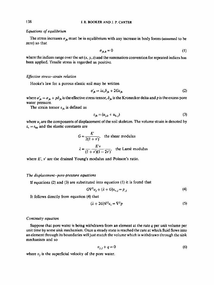
Equations of equilibrium
zero) so that The stress increases f s j k must be in equilibrium with any increase in body forces (assumed to be
Ojk.k = (1)
where the indices range over the set (x, y , z ) and the summation convention for repeated indices has been applied. Tensile stress is regarded as positive.
Effective stress-strain relation
Hooke’s law for a porous elastic soil may be written
b ; k = 2&,6jk + 2G&jk (2) where uik = ujk + pajk is the effective stress tensor, 6 , is the Kronecker delta and p is the excess pore water pressure.
The strain tensor &jk is defined as
&jk = ( u j , k + uk. j ) (3) where uj are the components of displacement of the soil skeleton. The volume strain is denoted by 8, = &kk and the elastic constants are
G G=---- 2(1 + v’)’
the shear modulus
E V 2 = the Lam6 modulus (1 + v’)( 1 - 2v’)’
where E’, v’ are the drained Young’s modulus and Poisson’s ratio.
The displacement-pore-pressure equations
If equations (2) and (3) are substituted into equation (1) it is found that
G V u j + (A + G)&,,j = p , j
It follows directly from equation (4) that
(2. + 2G)V2&, = V 2 p
Continuity equation
Suppose that pore water is being withdrawn from an element at the rate q per unit volume per unit time by some sink mechanism. Once a steady state is reached the rate at which fluid flows into anelement through its boundaries will just match the volume which is withdrawn through the sink mechanism and so
where vj is the superficial velocity of the pore water.

POINT SINK IN A HALF SPACE 139
Darcy's law
water is governed by Darcy's law, so that It will be assumed that the material is homogeneous and isotropic and that the flow of the pore
Pore pressure equation
equation If equations (6), and (7) are combined it is found that the pore pressure satisfies the Poisson
($).ZP = q
It is perhaps worth noting at this stage that equation (8) implies that the determination of the excess pore pressure p is completely uncoupled from the determination of the displacements, equation (4).
SOLUTION WHEN THE SINK IS INFINITELY DEEP
As a first step in the solution process we shall investigate the case where the sink is buried at great depth. The solution for a sink at finite depth can then be obtained by superposition of this solution and a correction term. The correction term can be obtained by using double Fourier transforms and this is discussed in the next section; the solution for the sink at infinite depth may be obtained by elementary means, however the relationship between it and the correction term is most elegantly derived by using a triple Fourier transform and this is the procedure that will be adopted.
Solution using integral transforms
The solution may be obtained by using integral transforms:
(P*, v;,ss) = ( 1 / 2 4 3 rm rm s".. (p, uj , oj& - i(ux +By + Y')dxdydz (9)
where J, k stand for any of the indices x, y, z. Equation (9) is, of course, equivalent to the representation
UdSdY (10) ( p , u j ~ ~ j ~ ) = l ~ m j r n Im (p*, u;, s$)e + i ( a + BY + Yz)d - m - m
Equation (8) becomes, upon transformation
where
and
- ( ;)D2P* + Q* = 0
Dz =az + j?' + y 2

140 J. R. BOOKER AND J. P. CARTER
Equations (4) become, upon transformation
- GD2U: + ( A + G)iaE: = iabP* - GD2 U: + (A + G)i/lE,* = i/lbP* - GD2 U y + (A + G)iyE: = iyP*
where iaU: + igU? + iyUt = E:. It is readily shown that the solution of equation (12) is
P* = (A + 2G)E,* and
The stresses can be found from the transformed versions of equations (2) and thus
Szx= - 2 G ( 1 - $ ) E :
S:,= -2G( 1 - $ ) E :
YS D2
aY D2
Pa D 2
Sy,, = + 2G- E:
S:,= + 2G-EE,*
S& = + 2G- E:
Solution for a point sink
(14)
If fluid is being removed (pumped) from a point sink of strength F located at the origin, then
where 6(x) is the Dirac delta function. It follows from equation (1 lb) that
c
Equation (12) may be used to determine the field quantities. The pore pressure distribution is given
e i ( a = + B ~ + ~ z ) by
= $ /ya /:a - a D2 dadpdy (164
141 POINT SINK IN A HALF SPACE
ox, A 2G 2R
%=-- 2G &(I+$)
ozz A 2G 2R
_- - --( 1 +$)’
_- - --( 1 +$)
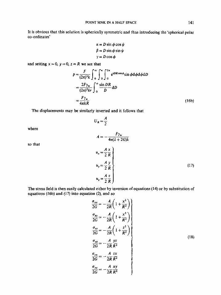
It is obvious that this solution is spherically symmetric and thus introducing the ‘spherical polar co-ordinates’
\
a = Dsin 4 cos JI 1 = D sin 4sin t,b Y = D C O S ~
and setting x = 0, y = 0, z = R we see that
F Y W =- 4akR
The displacements may be similarly inverted and it follows that
A U,=- L
where
so that
A = - Fyw 4 4 + 2G)k
A x
u =-- 2 R
The stress field is then easily calculated either by inversion of equations (14) or by substitution of equations (16b) and (17) into equation (2), and so
142 J. R. BOOKER AND J. P. CARTER
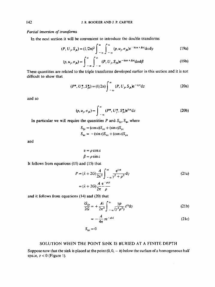
Partial inversion o j transforms
In the next section it will be convenient to introduce the double transforms
(p , uj, Sje) = (1/2n12 (p, uj, cjk)e - + @Y)dxdy ( 194
These quantities are related to the triple transforms developed earlier in this section and it is not difficult to show that
(P*, Uy, S$) = (1 /2~) ( P , U j , Sjk)e-"'dz Sr , and so
( p , Uj, ojk) = (P*, uy, S$)eiYzdZ !Im In particular we will require the quantities P and S,,, S,, where
S,, = (cos s)S,, + (sin s)Syz
S,: = - (sin E)S,, + (cos &)Syz
and
u = pcoss f l=ps in&
It follows from equations (1 1) and (15) that
and it follows from equations (14) and (20) that
SOLUTION WHEN THE POINT SINK IS BURIED AT A FINITE DEPTH
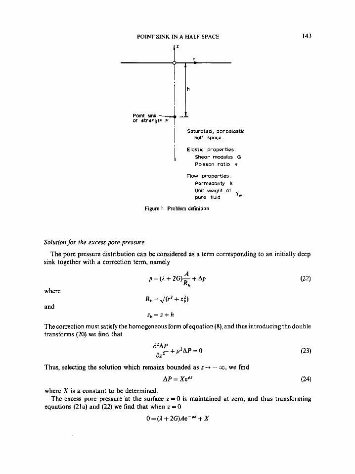
Suppose now that the sink is placed at the point (O,O, - h) below the surface of a homogeneous half spaze, z < 0 (Figure 1).
POINT SINK IN A HALF SPACE
I I n
143
Point sink of StrQngth F
I SatUratQd, poroelastic half SpoCQ.
Elastic proporties: Shoar modulus G Poisson ratio \I
i Flow proportios.
Pormeability k Unit woight of pure fluid y w
Figure 1 . Problem definition
Solution for the excess pore pressure
sink together with a correction term, namely The pore pressure distribution can be considered as a term corresponding to an initially deep
where
and
A p = ( A + 2G)- + Ap
R b
R , = J(r' + z;) z , = z + h
The correction must satisfy the homogeneous form of equation (8), and thus introducing the double transforms (20) we find that
a2AP a22 + p 2 A P = 0
Thus, selecting the solution which remains bounded as z -, - co, we find
AP = XePz (24)
The excess pore pressure 'at the surface z = 0 is maintained at zero, and thus transforming where X is a constant to be determined.
equations (21a) and (22) we find that when z = 0
0 = ( A + 2G)Ae-ph + X

144 J. R. BOOKER AND J. P. CARTER
a2Au aAE, G[ 5 - pzAUz] +(A + G)-- = 0
a z 2 aZ aAu,
ipAU, + __ - - AEv ,
and hence
where
A AP = - (A + 2G)--ePza
2XP z , = z - ~
Equation (25) can be inverted immediately by comparison with equation (21) and thus
where
A Ap = -(A + 2G)-
Ra
R, = J ( r 2 + z t )
The complete solution can now be expressed as
and so, as might be expected, the excess pore pressure distribution may be interpreted as due to a point sink placed at (O,O, - h) in an unbounded medium with an image source of equal strength placed at (O,O, + h), in an unbounded medium.
Solutions for displacement and stress
Once the solution for the excess pore pressures is known we can solve equations (4) to obtain the displacements. A particular solution of those equations is immediately obvious (that correspond- ing to a sink and a source in an unbounded medium) and thus
u =- _-_ "( 2 Rb
, The transformed displacement components satisfy the equations
a2Aus az2
G[ - - p'AU,] + (3, + 2G)ipAE, = 0
where it has been convenient to introduce the auxiliary variables
AVs = (cos E)AU, + (sin E)AU, AU,, = (sin E)AU, + (cos E)AU,
POINT SINK IN A HALF SPACE 145
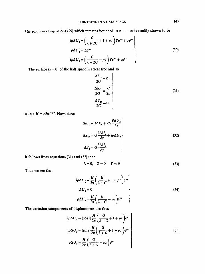
The solution of equations (29) which remains bounded as z + - m is readily shown to be
iAS,, H 2G 2K
-=-
4 - 0 2G
G ipAU,= ___
( L + 2 G
pAU, = Lepz
ipAU, = (= G - pi) YePz + zepz
*
The surface (z = 0) of the half space is stress free and so
adu, a Z
AS,, = G - + ipAU,
aAU, a Z
AS,, = G -
it follows from equations (31) and (32) that
L=O, Z=O, Y = H
Thus we see that
ipAU,=- 2n: ( - L + G + 1 +pz)epZl
t AU,, = 0
p A ( J , = E ( L - p z ) e " 2K L + G
The Cartesian components of displacement are thus
pAUz = E 2n: (L 1 + G - pz)eP'
(33)
(34)
(35)

146 J. R. BOOKER AND J. P. CARTER
The displacements in cylindrical polar co-ordinates are thus
AUe=O
AUr = 1: H ( A+G G + 1 + pz)epzJ,(pr)dp
Thus it is found that
Au, = 0
1 zz, -_ - 2 - (A ," G ) R . + R,3 We thus see that the vertical movement (settlement) of the surface is given by
where R, = J(r2 + h2).
Equations (36) can be used to find the non-zero stress components and these are
1 2G
- = A h { $ + Ace, (E) 1 2G A+G R,(Ra-za)
2G
(37)
(39)
RESULTS
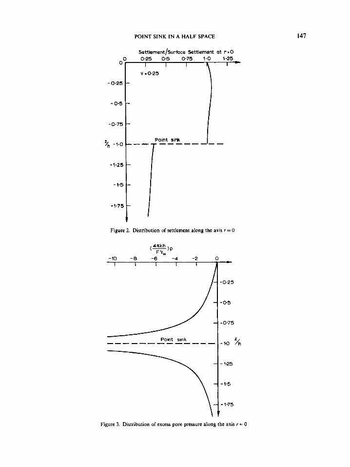
The solutions presented in equations (18), (26), (27), (36), (37) and (38) have been evaluated for the particular case of r = 0, i.e. along the vertical axis containing the sink. The distributions of displacement, excess pore pressure and changeof effective stress are plotted in Figures 2,3 and 4 for a soil skeleton having a Poisson's ratio of 0.25. In addition, the profile of vertical settlement of the surface is also plotted in Figure. 5.
It is clear from Figure 2 that the vertical movement along the axis above the sink is almost uniform; the surface displacement at r = 0 is given by the expression
A + 2 G F A (z) = - 4n(A+ G)(k/y , )
0
- 0-25
- 0.5
-0.75
Yh -1.0
-1-25
- 1.5
-1.75
POINT SINK IN A HALF SPACE
Figure 2. Distribution of settlement along the axis r = 0
-10 -0 -6 -4 -2 I I I I 1
-0.25
- 05
- 0.75
-lQ ‘/h
- 1.25
- 1.5
-1-75
147
Figure 3. Distribution of excess pore pressure along the axis r = 0

148 J. R. BOOKER AND J. P. CARTER
where the negative sign indicates a settlement. It is notable that the magnitude of this settlement is independent of the depth of the embedment. There is a discontinuity in displacement at the location of the sink but at no other point. This discontinuity is due to considering the physically artificial but mathematical convenient case of a point sink; if the sink were distributed over a finite region no such discontinuity would exist. Beneath the sink the material also settles but the magnitude of this movement decays slowly with depth.
Figure 3 shows the distribution with depth of the pore pressure change p. The value of p decreases with depth from zero at the surface and is unbounded at the location of the sink. Beneath the sink the excess pore pressure asymptotically approaches zero again. As can be seen from equation (27) the magnitude of these pore pressure changes is proportional to the quantity
i.e. it is proportional to the strength of the sink and inversely proportional to the permeability of the soil.
The changes in effective stress along the axis, where triaxial stress conditions prevail (a,, = age, a,, = 0), are plotted in Figure 4. Along the entire axis all of the effective stress components experience long-term changes which are compressive in nature. This accounts for the settlements that are predicted within the soil mass and at the surface. The changes in total stress can be found from Figures 3 and 4 using the principle of effective stress.
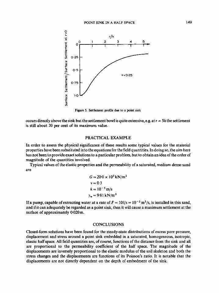
Finally, the surface settlement profile is indicated in Figure 5. Of course, the greatest settlement
-12 -9 -6 -3 0 I
Compression
Figure 4. Distribution of erective stress along the axis r = 0
POINT SINK IN A HALF SPACE 149
9 c r/h - 0 1 2 3 4 5 g o I I I I I * EJ - 4a c
2 0.25 - P)
F
V = 0.25
0 L
v)
c
Figure 5. Settlement profile due to a point sink
occurs directly above the sink but the settlement bowl is quite extensive, e.g. at r = 5h the settlement is still about 20 per cent of its maximum value.
PRACTICAL EXAMPLE
In order to assess the physical significance of these results some typical values for the material properties have been substituted into the equations for the field quantities. In doing so, the aim here has not been to provideexact solutions to a particular problem, but to obtain an idea of the order of magnitude of the quantities involved.
Typical values of the elastic properties and the permeability of a saturated, medium dense sand are
G = 20.0 x lo3 kN/m2 v = 0.3 k = lO-’m/s
yw = 9.8 1 kN/m3
If a pump, capable of extracting water at a rate of F = 1Ol/s = m3/s, is installed in this sand, and if it can adequately be regarded as a point sink, then it will cause a maximum settlement at the surface of approximately 0020m.
CONCLUSIONS
Closed-form solutions have been found for the steady-state distributions of excess pore pressure, displacement and stress around a point sink embedded in a saturated, homogeneous, isotropic, elastic half space. All field quantities are, of course, functions of the distance from the sink and all are proportional to the permeability coefficient of the half space. The magnitude of the displacements are inversely proportional to the elastic modulus of the soil skeleton and both the stress changes and the displacements are functions of its Poisson’s ratio. It is notable that the displacements are not directly dependent on the depth of embedment of the sink.
150 J. R. BOOKER AND J. P. CARTER
It has also been demonstrated that a pump capable of withdrawing pore water from the soil at a rate of 1Ol/s in a sand of medium density could typically cause a maximum surface settlement of about 0.02 m (independent of the depth of embedment).
Finally it is worth noting that the solution developed in this paper and summarized by equations (18), (26), (27), (36), (37) and (38) can be used as a fundamental or Green’s function solution in applications of the boundary integral method and this will appear in a subsequent paper.
REFERENCES
1. R. F. Scott, ‘Subsidence-a review’, in S. K. Saxena (ed.), Eualuation and Prediction of Subsidence, ASCE, New York,
2. A. P. Delfranche, ‘Land subsidence versus head decline in Texas’, in S. K. Saxena (ed.), Evaluation and Prediction of
3. 9. E. Lofgren,‘Changes in aquifer-system properties with ground water depletion’, in S. K. Saxena (ed.), Evaluation and
4. J. Premchitt, ‘Land subsidence in Bangkok, Thailand: results of initial investigation’, 1978, Geotechnical Engineering,
5. Y. Harada and T. Yamanouchi, ‘Land subsidence in saga Plain, Japan and its analysis by the quasi three-dimensional
6. J. Bear and G. F. Pinder, ‘Porous medium deformation in mu1tiDhm flow’, J . Eng. Mech. Din. ASCE, lM(EM4). 881-
1978, pp. 1-25.
Subsidence, ASCE, New York, 1978, pp.320-331.
Prediction of Subsidence, ASCE, New York. 1978, pp. 26-46.
lo(]), 49-76 (1979).
aquifer model’, Geotechnical Engineering, 14( I), 23-54 (1983).
894 (1978).
Prediction of Subsidence. ASCE, New York, 1978, m. 400-416. 7. R. W. Lewis and B. A. Schrefler, ‘A finite element analysis of surface-subsidence’, in S. K. Saxena (ed.), Evaluation and
8. R. S. Sandh;, ‘Modeling land subsidence’, in S. K. Skena (ed.), Evaluation and Prediction of Subsidence, ASCE, New
9. S. K. Saxena and A. Mohan, ‘Study of subsidence due to withdrawal of water below an aquitard‘, in S. K. Saxena (ed.),
10. A. D. W. Sparks, ‘Numerical methods for the settlement of Venice and layered soil deposits’, Proc. Third Int. ConJ on
York, 1978, pp. 565-579.
Evaluation and Prediction of Subsidence, ASCE, New York, 1978, pp. 332-348.
Num. Meth. in Geomechs., Aachen, W. Germany, 1979, Vol. 1, pp.213-225.