“analysis and design of multistored building in hilly
TRANSCRIPT
International Research Journal of Engineering and Technology (IRJET) e-ISSN: 2395-0056
Volume: 07 Issue: 04 | Apr 2020 www.irjet.net p-ISSN: 2395-0072
© 2020, IRJET | Impact Factor value: 7.529 | ISO 9001:2008 Certified Journal | Page 3015
“ANALYSIS AND DESIGN OF MULTISTORED BUILDING IN HILLY AREAS
USING STADD PRO”
Nikhil Ghuge1, Neha Shahare2, Mohini Tupsunder3, Shivram Totewad4,
Nikhil Gaydhani5, Kushal Yadav6
1-6Department of Civil Engineering, Wainganga College of Engineering And Management Wardha Road, Dongargaon, Nagpur, Maharashtra-44114
---------------------------------------------------------------------***----------------------------------------------------------------------
Abstract– India is the most populated country in the world. The on Hill is differ from other building. The Hilly Region is pulling construction industry towards it because most of the plain land is occupied for the purpose of urbanization and industrialization. To fulfill the need of housing for population it becomes to construct multistoried building in hilly region because plain land is scarcely available in urban areas. 3D Analytical model of G+5 is multistoried residential building have been generated and analyzed by using analysis tool “STADD-pro”. The drafting and detailing work is done by using drafting software AUTO-cad. This paper is properly planed Analysis and design the D+5 Residential RCC Building Constructed in hilly region using with IS code 456-2000. Key Words: housing in hilly areas , STADD-pro, multi storied, AUTO-cad.
1. INTRODUCTION: Due to increasing in population now a days in hilly region we have to construct multistoried building in hilly areas.
This project is Analysis and Design of hilly area multistoried residential building [G+5] using very popular analytical and designing software STADD-pro. Reason of choosing this software is it gives accuracy of solution, versatile nature of solving of problems, confirmation of IS codes.
Building in hilly area subjected to the lateral earth pressure at various levels in addition to other normal loads as specified on building on level ground. The soil profile is not uniform and the result into total collapse of the building. The bearing capacity, cohesion, angle of internal friction etc. this project is drafted in drafting software AUTO-cad and after the plan is import in STADD-pro.
1.1 Literature Review Shaikh imran, P.Rajesh (January 2017): Earth quake Analysis of RCC Building in Hilly:
The performance of irregular plan shaped building with vertical irregularity could prove more vulnerable than the regular plan shaped building with vertical irregularity. On plan ground, setback building attract less action forces as comparing with other configurations on sloping ground which make it more stable and it would not suffer more damages due to the lateral load action. On sloping ground set-step back building attract less action forces as comparing with step back building but if the cutting cost of sloping ground is with acceptable limits then setback building may be preferred. In step back building, the development of storey shear and moment and torsion were more than other configuration which found to be more vulnerable. Mr. Tamboli Nikhil Vinod, et.al (2017): Stud Of Seismic Behavior Of Multi- Storied RCC Building Resting On Sloping Ground And Bracing System: The height and length of building in a particular pattern are in multiple of blocks (in vertical and horizontal direction), the size of block is being maintained at 7 m x 5 m x 3.5 m. The height of all floors is 3.5m The depth of footing below ground level is taken as 1.8 m where, the hard stratum is available. The slope of ground is 27 degree with horizontal, which is neither too steep or nor too flat. Basically model consists of two bays with four groups of building configurations. The dynamic analysis is carried out using response spectrum method to the step back and step back and step back building frames. Three dimensional space frame analysis is carried out for four different configurations of buildings ranging from eight, ten and twelve storey resting on sloping ground under the action of seismic load by using E-tabs software. In these way to analysis of these system.
International Research Journal of Engineering and Technology (IRJET) e-ISSN: 2395-0056
Volume: 07 Issue: 04 | Apr 2020 www.irjet.net p-ISSN: 2395-0072
© 2020, IRJET | Impact Factor value: 7.529 | ISO 9001:2008 Certified Journal | Page 3016
Rahul Manojsingh Pawar (June 2017) : Analysis Of Set Back Step Back Building Resting On Sloping Ground: Buildings resting on sloping ground have less base shear compared to buildings on Plain ground. Base shear increases as slope of ground increase Buildings resting on sloping ground have more lateral displacement compared to buildings on Plain ground. Buildings with set back – step back is showing less displacement than step back model. Building is showing high value of displacement in z- direction than in x direction. The critical axial force in columns is more on plain ground than on sloping ground. The shear force and moment in columns is more on sloping ground than on plain ground. The shear force and bending moment value in beams is high in plain ground model than on sloping ground model. The performance of set- step back building during seismic excitation could prove more vulnerable than other configurations of Buildings. The development of moments in set - step back buildings is higher than that in the set-back building. Hence, Set back building are found to be less vulnerable building against seismic ground motion. Step back Set back buildings, overall economic cost involved in leveling the sloping ground and other related issues needs to be studied in detail.
Inguva Sai surya prakash, et.al (2018): A Study On Comparative Analysis Of RCC Building Resting On Plain And Hilly Terrain. Although, the buildings on plain ground attract less action forces as compared to buildings on sloping ground, overall economic cost involved in levelling the sloping ground. In buildings on sloping ground, it is observed that extreme left column at ground level, which are short, are the worst affected. Special attention should be given to these columns in design and detailing. The graph shows that there is significant reduction in bending moments of columns in Z Direction from R.C.C Structure on Plain Ground and Sloping Terrain. Base shear of R.C.C Structure on sloping terrain is very less compared to R.C.C structure plain ground. The storey drift in R.C.C Structure on Plain Ground and Sloping Terrain is nearly equal. This is because; steel structure is more flexible as compared to RCC structure. Bending moment is seem to be reduced due to step up columns in R.C.C Structure on sloping terrain. The bending moment in column is increase at base of frame due to the long column and short column effect in R.C.C Structure on sloping ground. From the study, it is observed that the building which are resting on sloping are subjected to short column effect , attract more forces and are worst affected during seismic excitation. Hence form design point of view, special attention should be given to the size, orientation, and ductility demand of short column
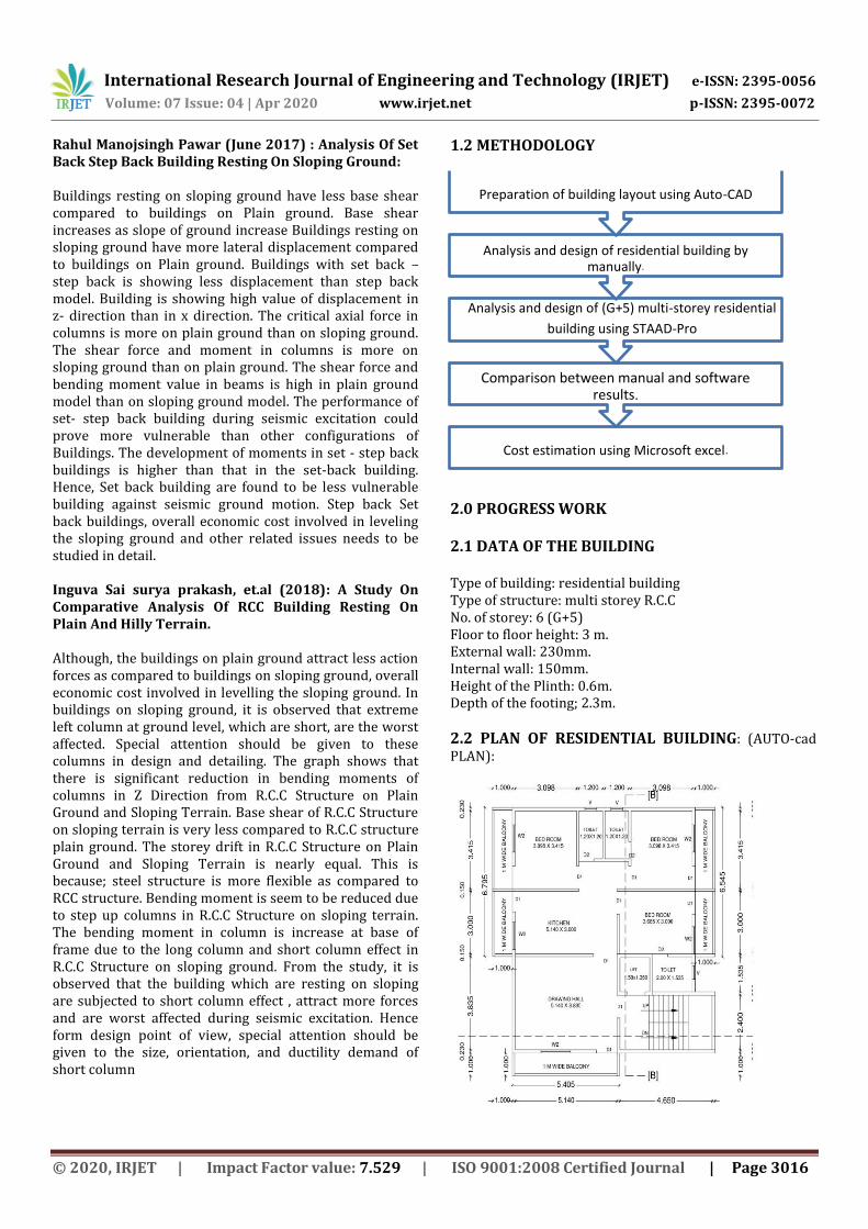
1.2 METHODOLOGY
2.0 PROGRESS WORK 2.1 DATA OF THE BUILDING Type of building: residential building Type of structure: multi storey R.C.C No. of storey: 6 (G+5) Floor to floor height: 3 m. External wall: 230mm. Internal wall: 150mm. Height of the Plinth: 0.6m. Depth of the footing; 2.3m.
2.2 PLAN OF RESIDENTIAL BUILDING: (AUTO-cad PLAN):
Cost estimation using Microsoft excel .
Comparison between manual and software results .
Analysis and design of (G+5) multi-storey residential
building using STAAD-Pro
Analysis and design of residential building by manually .
Preparation of building layout using Auto - CAD
International Research Journal of Engineering and Technology (IRJET) e-ISSN: 2395-0056
Volume: 07 Issue: 04 | Apr 2020 www.irjet.net p-ISSN: 2395-0072
© 2020, IRJET | Impact Factor value: 7.529 | ISO 9001:2008 Certified Journal | Page 3017
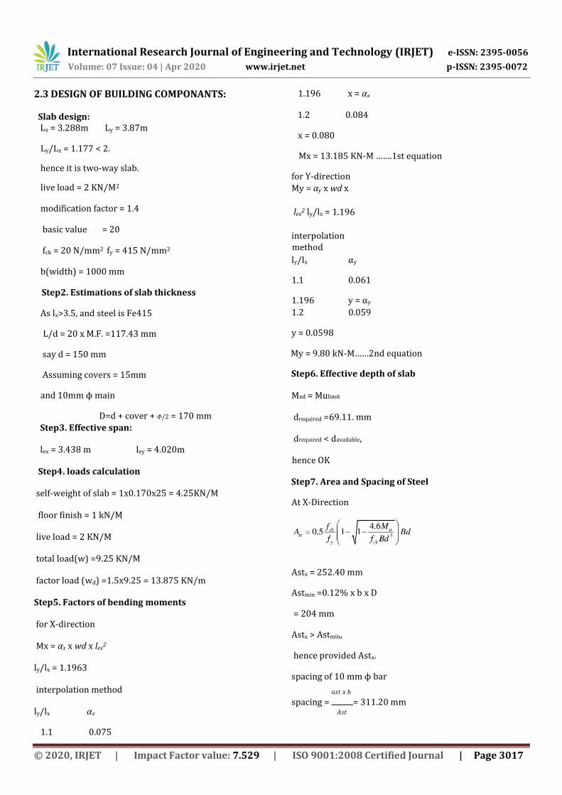
2.3 DESIGN OF BUILDING COMPONANTS: Slab design: Lx = 3.288m Ly = 3.87m
Ly/Lx = 1.177 < 2.
hence it is two-way slab.
live load = 2 KN/M2
modification factor = 1.4
basic value = 20
fck = 20 N/mm2 fy = 415 N/mm2
b(width) = 1000 mm
Step2. Estimations of slab thickness
As lx>3.5, and steel is Fe415
L/d = 20 x M.F. =117.43 mm
say d = 150 mm
Assuming covers = 15mm
and 10mm ϕ main
D=d + cover + 𝛷/2 = 170 mm Step3. Effective span:
lex = 3.438 m ley = 4.020m
Step4. loads calculation
self-weight of slab = 1x0.170x25 = 4.25KN/M
floor finish = 1 kN/M
live load = 2 KN/M
total load(w) =9.25 KN/M
factor load (wd) =1.5x9.25 = 13.875 KN/m
Step5. Factors of bending moments
for X-direction
Mx = αx x wd x lex2
ly/lx = 1.1963
interpolation method
ly/lx αx
1.1 0.075
1.196 x = αx
1.2 0.084
x = 0.080
Mx = 13.185 KN-M …….1st equation
for Y-direction
My = αy x wd x
lex2 ly/lx = 1.196
interpolation method ly/lx αy
1.1 0.061
1.196 y = αy 1.2 0.059
y = 0.0598
My = 9.80 kN-M……2nd equation
Step6. Effective depth of slab
Mxd = Mulimit
drequired =69.11. mm
drequired < davailable,
hence OK
Step7. Area and Spacing of Steel
At X-Direction
Astx = 252.40 mm
Astmin =0.12% x b x D
= 204 mm
Astx > Astmin,
hence provided Astx.
spacing of 10 mm ϕ bar
𝑎𝑠𝑡 𝑥 𝑏 spacing = = 311.20 mm
𝐴𝑠𝑡
International Research Journal of Engineering and Technology (IRJET) e-ISSN: 2395-0056
Volume: 07 Issue: 04 | Apr 2020 www.irjet.net p-ISSN: 2395-0072
© 2020, IRJET | Impact Factor value: 7.529 | ISO 9001:2008 Certified Journal | Page 3018
2
say as spacing = 240 mm …….1st
equation
S=3d = 450 mm ……...2nd equation
S=300 mm……...3rd equation
provide minimum value.
At Y-Direction d' = d- ϕ = 140 mm
Asty = 200.053mm
Asty < Astmin,
hence provided Astmin
spacing of 8 ϕ mm
𝑎𝑠𝑡 𝑥 𝑏 spacing = = 246.431 mm
𝐴𝑠𝑡𝑚𝑖𝑛
say spacing = 225mm
S=3d' = 420 mm
S=300mm
provided minimum value
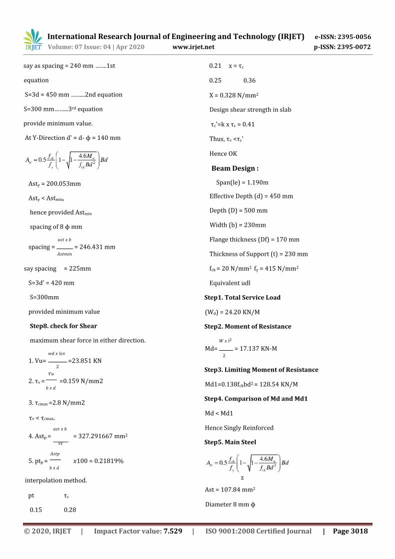
Step8. check for Shear
maximum shear force in either direction.
𝑤𝑑 𝑥 𝑙𝑒𝑥 1. Vu= =23.851 KN
𝑉𝑢 2. τv = =0.159 N/mm2
𝑏 𝑥 𝑑
3. τcmax =2.8 N/mm2
τv < τcmax.
𝑎𝑠𝑡 𝑥 𝑏 4. Astp = = 327.291667 mm2
𝑠𝑥
𝐴𝑠𝑡𝑝 5. ptp = 𝑥100 = 0.21819%
𝑏 𝑥 𝑑
interpolation method.
pt τc
0.15 0.28
0.21 x = τc
0.25 0.36
X = 0.328 N/mm2
Design shear strength in slab
τc'=k x τc = 0.41
Thus, τv <τc'
Hence OK
Beam Design :
Span(le) = 1.190m
Effective Depth (d) = 450 mm
Depth (D) = 500 mm
Width (b) = 230mm
Flange thickness (Df) = 170 mm
Thickness of Support (t) = 230 mm
fck = 20 N/mm2 fy = 415 N/mm2
Equivalent udl
Step1. Total Service Load
(Wd) = 24.20 KN/M
Step2. Moment of Resistance
𝑊 𝑥 𝑙2 Md= = 17.137 KN-M
2
Step3. Limiting Moment of Resistance
Md1=0.138fckbd2 = 128.54 KN/M
Step4. Comparison of Md and Md1
Md < Md1
Hence Singly Reinforced
Step5. Main Steel
z
Ast = 107.84 mm2
Diameter 8 mm ϕ

International Research Journal of Engineering and Technology (IRJET) e-ISSN: 2395-0056
Volume: 07 Issue: 04 | Apr 2020 www.irjet.net p-ISSN: 2395-0072
© 2020, IRJET | Impact Factor value: 7.529 | ISO 9001:2008 Certified Journal | Page 3019
bar Area of bars =
50.240 mm2
Number of bars
= 2.840
Bars Provided = 3 NOS
Ast Provided =150.720 mm2
Step6. Design of Shear
a) Shear Force, Vu=W x le = 28.798 KN
b) Nominal Shear Stress
𝑉𝑢 τv= = 0.278
𝑏 𝑥 𝑑
c) τcmax=2.8 N/mm2
τv < τcmax, OK
d) Shear strength of concrete, τc
𝐴𝑠𝑡 Pt= 𝑥100 = 0.146%
𝑏 𝑥 𝑑
0.150 0.280
0.250 0.360
τc = 0.276 N/mm2
e) As τv > τc
Shear Reinforcement is Required.
f) Shear Force
Vus= vu-(τc.bd) = 180.40 KN
Vusv=Vus
Provided 6 mm ϕ two legged M.S. Vertical Stirrups
g) Spacing
0.87𝑓𝑦.𝐴𝑠𝑡.𝑑 Sv = = 30664.60 mm
𝑉𝑢𝑠𝑣
Check,
01) Minimum Spacing
= 133.621 mm 0.4𝑏
02) Maximum Spacing
0.75d or 300 mm
Provided Spacing 300 mm
Step8. Check for Development length
0.87𝑓𝑦𝛷 Ldrequired = = 169.922 mm
4𝜏𝑏𝑑
Ldavailable = t+(8 ϕ -d') = 253 mm
Step9. Check for Serviceability
Pt required = 0.146
Modification factor = 1.38
Basic L/d (rb) = 7.0
Allowable L/d (ra) = 9.660
Required d=L/d (ra) = 123.188
Design of column
Step1. Axial Load = 2036.12 KN
Step2. Size of column
L = 3000 mm b = 230 mm
Step3. Percentage of steel (Asc)
Pt > 0.8%Pt < 6%
Assuming percentage (%) = 2.0
Asc = 2%Ag = 0.02
Ac=0.02Ag = 0.98
Step4. Depth Required
Pu=0.4fckAc+0.67fyAsc
Ag = 151960.30 mm2
D=Ag/b = 660.70 mm
Provided D =680 mm
Provided Ag = 156400.00 mm2
Step5.Check for Eccentricity and Slenderness ratio
Le/D = 4.41 Le/D<12 OK
L D emin= + =28.67
50 30 mm
emin > 20 mm
International Research Journal of Engineering and Technology (IRJET) e-ISSN: 2395-0056
Volume: 07 Issue: 04 | Apr 2020 www.irjet.net p-ISSN: 2395-0072
© 2020, IRJET | Impact Factor value: 7.529 | ISO 9001:2008 Certified Journal | Page 3020
emax = 0.05D =
34.00 mm
emin < emax OK
Step6. Area of Steel and Percentage Steel
Asc required = 3128 mm2
Bar used 25 mm ϕ
Area of bar =
490.63 mm2
No. of bars Required = 6.38
No. of bars
Provided=8
Ast Provided = 3925
mm2
Pt of steel provided = 2.51
Pt>0.8%Pt<6%OK
Step7. Design of transverse steel
a) Diameter of links = x ϕ and
6 mm Greater is 6.25 mm
Say 8 mm dia. of link
b) Spacing
i)least lateral dimension = 680 mm
ii)16ϕ = 400 mm
iii)300 mm
Provided Spacing = 300 mm
Reinforcement Details 8 No.-25mm at 300 mm c/c.
Design of Staircase
Type of slab = Waist slab
Riser =150 mm Tread = 270 mm
Height =3 m
No. of riser = 20nos
No. of riser in each flight=10nos
No. of trends in each flights =9nos
Going(G)=3.115m
Provided width of landing = 0.9m
Width of stair= 1.027m
Live load = 3 KN
fck =20 N/mm2 fy = 415 N/mm2
Effective span
= Going + half of support + half of support
=3.115+0.9/2+0.9/2
=4.015m
M.F. = 1.6
2.0 Load and bending moment
Assume depth of slab D =170mm
Assume width of slab =1000mm
(a) Load of slab per meter of horizontal span = 4.861KN/m
(b) Steps:
Load on one step=1/2*R*T*25=0.50625KN
Load of step per meter=0.50625*1/0.27=1.875KN/m
(c) Live load=3 KN/m (d) Floor finish= 1 KN/m
Total load w= 10.7361KN/m Factored load wd=16.104KN/m Factored moment Md = 32.450 KN/m
3.0 Depth of slab:
0.138*bd^2*fck = Md
d^2= 11976.27mm
d = 109.4m
Assuming 10mm dia of bar and 25mm cover =139.4mm
139.4mm<170mm OK
Depth required for deflection = 125.46mm
D =170mm
D= 140mm
4.0 Calculate Main Steel
Ast = 718.89 mm2
Provide 10 mm ϕ bar
Area of bar = 78.54
mm2
𝐴𝜙 Spacing = 𝑥1000
International Research Journal of Engineering and Technology (IRJET) e-ISSN: 2395-0056
Volume: 07 Issue: 04 | Apr 2020 www.irjet.net p-ISSN: 2395-0072
© 2020, IRJET | Impact Factor value: 7.529 | ISO 9001:2008 Certified Journal | Page 3021
𝐴𝑠𝑡
= 109.25 mm, say 100 mm c/c
5.0 Area of distribution Steel
Astd = 0.15%of b.D
= 225 mm2
Provide 6 mm ϕ bars
𝐴𝜙 Spacing = 𝑥1000
𝐴𝑠𝑡𝑑
= 110.82mm say110 mm
(<5d or 450mm whichever is less, <5*120 or 450=4
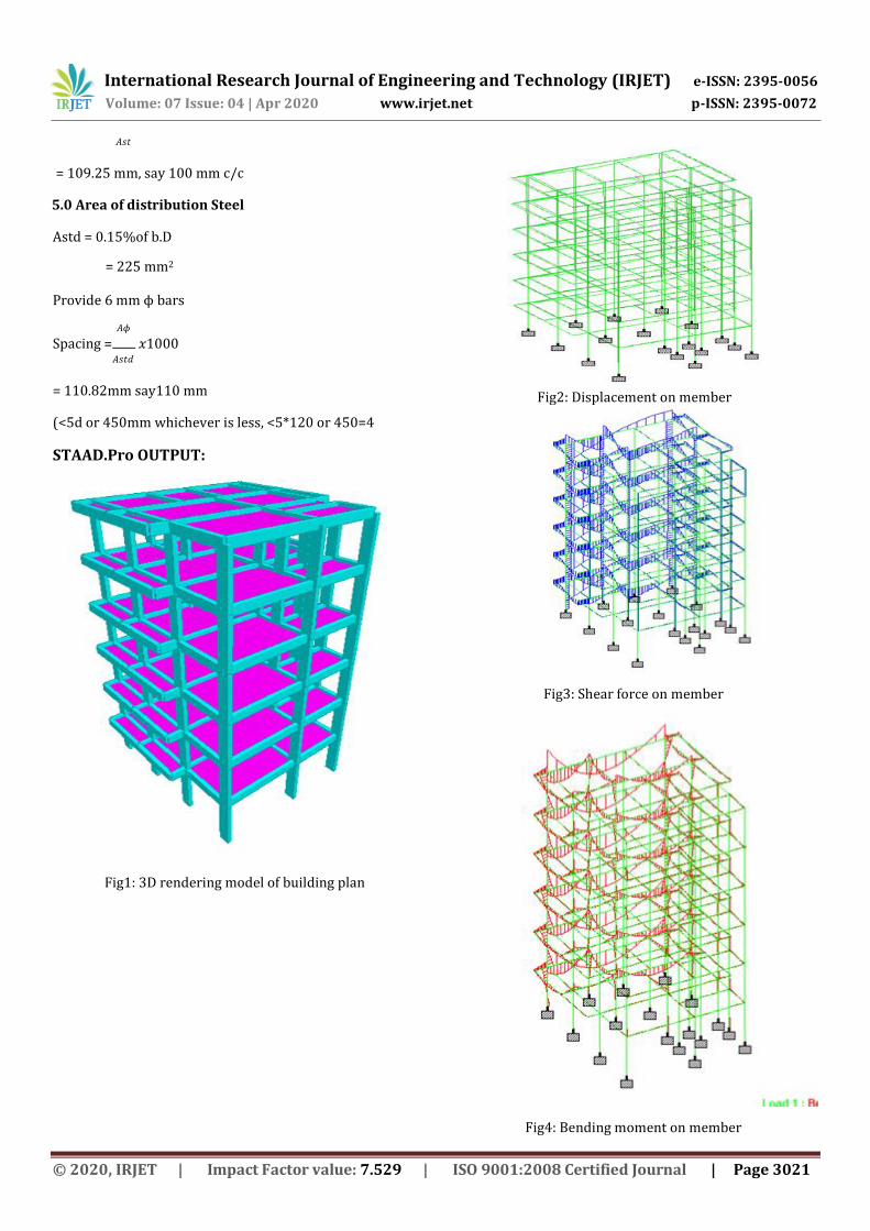
STAAD.Pro OUTPUT:
Fig1: 3D rendering model of building plan
Fig2: Displacement on member
Fig3: Shear force on member
Fig4: Bending moment on member

International Research Journal of Engineering and Technology (IRJET) e-ISSN: 2395-0056
Volume: 07 Issue: 04 | Apr 2020 www.irjet.net p-ISSN: 2395-0072
© 2020, IRJET | Impact Factor value: 7.529 | ISO 9001:2008 Certified Journal | Page 3022
3. CONCLUSIONS
1. This paper is based on design and analysis multistoried residential building(G+5) using commercial software STAAD-pro.
2. Plan of the building is drafted with the help of the drafting software with required dimensions.
3. We applied different kind of the loads on the building Earthquake load, live load and the respective load combination. We found the structure is capable to sustain applied loads.
4. It is included that with the help of the using software STAAD-pro etc, there is possibility of having stable and safe construction of the structure with the provided load.
5. By using the STAAD-pro software it is easy to get fast, efficient and accurate platform for analyzing and designing software.
REFERENCES
1. Harish K S, Akash K, Amith A P, Asha S V, Harish R. Olekar, Analysis Of Multistoreyed Building (G+4) In Sloped Ground, International Journal for Research in Applied Science & Engineering Technology (IJRASET), ISSN: 2321-9653; IC Value: 45.98; SJ Impact Factor:6.887 Volume 5 Issue VIII, July 2017.
2. Tamboli Nikhil Vinod, Dr. Ajay Swarup, Study Of Seismic Behavior Of Multi-storied R.C.C. Buildings Resting On Sloping Ground And Bracing System, IJARIIE, ISSN(O)-2395-4396, Vol-3 Issue-4 2017.
3. Shaik Imran, P. Rajesh, Earthquake Analysis of RCC Buildings on Hilly, IJSART, Volume 3 Issue 1 –JANUARY 2017, ISSN: 2395-1052.
4. Achin Jain, Rakesh Patel, Analysis Of Building Constructed On Sloping Ground For Different Types Of Soil, International Journal For Technological Research In Engineering, Volume 4, Issue 12, August-2017, ISSN: 2347 - 4718.
5. Inguva Sai Surya Prakash, Adireddy Siva Satya Vara Prasad, R Rama Krishna, A Study on Comparative Analysis of RCC Building Resting on Plain and Hilly Terrain, International Journal for Scientific Research & Development, Vol. 6, Issue 01, 2018 | ISSN (online): 2321-0613
6. Design of Reinforced concrete structure by S. Ramamrutham.
7. IS CODE 456-2000. 8. IS CODE 875-1987 (Part 1,2 and 3). 9. Design of R.C.C. Structures by Nirali Prakashan.
BIOGRAPHIES
Nikhil.B.Ghuge BE Final year student, Civil Department, Wainganga College of Engineering & Management Nagpur
Neha.Y.Shahare BE Final year student, Civil Department, Wainganga College of Engineering & Management Nagpur
Mohini.B.Tupsunder BE Final year student, Civil Department, Wainganga College of Engineering & Management Nagpur
Shivram Totewad BE Final year student, Civil Department, Wainganga College of Engineering& Management Nagpur
Nikhil Gaydhani BE Final year student, Civil Department, Wainganga College of Engineering & Management Nagpur
Kushal Yadav Assistant Professor Civil Department,
Wainganga College of Engineering & Management
Nagpur