analogue to digital conversion chapter 13. mbed adc as mentioned before, most sensors of...
TRANSCRIPT

Analogue to Digital ConversionChapter 13

mbed

ADC•As mentioned before, most sensors of temperature, sound, and acceleration have analog outputs. However, these analog outputs have to be converted into digital signals before they can be stored or used in calculations by the microcontroller.•Analog signals are converted into digital representations with a resolution and a rate determined by the Analog to Digital Converter (ADC).▫ An ADC is a circuit whose digital output is proportional to the analog
input.▫ Effectively, an ADC measures the input analog voltage, and gives a
binary output proportional to the size of the input signal.▫ The input range of the ADC is usually determined by the value of a
voltage reference (3.3 V)

ADC Block Diagram •The conversion process is started by a digital input called SC, start convert.▫ It takes a finite time to perform
the conversion, depending on the clock frequency.
▫ The ADC signals that the conversion is completed via the EOC, end of conversion line
•The resulting data can then be written onto the output data bus, when the output enable, OE control line, is high.
+ Analogueto Digital
- Converter
uuee
Analogue Digital Output(n bits)
Analog Input
SC(Start
Convert)
EOC(End of Conversion)
OE(Output Enable)
+
-
Voltage Reference
+
Example Control Lines
to DigitalConverter

2 bit ADC
http://www.asdlib.org/onlineArticles/elabware/Scheeline_ADC/ADC_ADC_Flash.html

•Many ADCs follow the relation where:
▫D is the digital output value ▫Vi is the analog input voltage▫Vr is the reference voltage▫n is the number of bits in the converter output
•How many voltage comparators are needed for a 12-bit ADC?
12 nscomparatorN
n
r
i
V
VD 2

•The output binary number is an integer, and for an n-bit number can take any value from 0 to (2n – 1 ).▫You may want to think about this.
•The ADC process rounds (truncates) the calculation to produce an integer output.
•An ADC will have maximum and minimum input values that it convert. The difference is the range.▫Often the minimum value is 0 V, so the range is then just the
maximum possible input value. Analog input values that exceed the maximum or minimum will likely be digitized as the maximum or minimum values (a limiting or clipping action occurs).

3 bit ADC
•This shows that in making the conversion, an approximation is involved as any one digital output value has to represent a range of analog input signals.▫ For example, if the output value of 100 is precisely correct in the middle of the step, the
greatest errors will occur at either end.
As input voltage goes from 0 V to Vmax, the digital output will step from 0 to 111 or (23-1)Range of analog
values all represented by 100

Error made by ADC
From Understanding Data Converters, Texas Instruments Application Note

Quantisation Error•The greatest quantisation error is one half of the step width, or half of one least significant bit (LSB) equivalent on the voltage scale.▫To reduce the quantisation error, the “step width” should be
narrowed. This can be achieved by increasing the number of bits in the ADC process. This increases complexity and cost, and often the time taken to
undertake the conversion.
•What is the step width and worst case quantisation error? o The LPC1768 ADC is 12 bit. o The reference voltage is taken from the regulated 3.3 V
supply.

Effect of Quantization Error
Quantization Noiseeg 8 bits A/D > ‐ noise floor is ~ 50 dB
From Understanding Data Converters, Texas Instruments Application Note

Sample and Hold
•When performing an analog to digital conversion, a “sample” is taken of analog signal and quantized to the accuracy defined by the resolution of the ADC.▫ The signal is held, which means that it is stored temporally while the
signal is compared to the reference voltage and the digital signal is generated.
•Sometimes, the digital signal is generated by averaging the results of several analog samples. The more samples taken, the more accurate the digital data will be as long as the analog signal is not changing. ▫ Sampling is generally done at a fixed frequency, called the sampling
frequency.

• http://www.seas.upenn.edu/~ese206/labs/adc206/adc206.html
S&H – Sample and Hold
Decoder – circuitry to change outputs of the n comparators to the digital signal.


The ideal sampling frequency depends on the maximum frequency of the signal being digitised. If the sampling frequency is too low, then rapid changes in the analog signal may not be represented in the resulting digital data.
Waveforms showing that undersampling results in the digitised output (lower traces) not representing the input waveforms (upper traces)
Sampling Frequency

Nyquist-Shannon Sampling Theorem•The Nyquist-Shannon sampling criterion states that the
sampling frequency must be at least double that of the highest frequency of interest.▫However, it is generally agreed that the sampling
frequency should be 5+ times the highest frequency found in the analog signal. If the highest frequency that is created when a human
speaks is 3.5 kHz, what is the minimum sampling frequency that should be used?
The name of the criterion is usually shortened one or the other names – Nyquist criterion or Shannon Criterion.

Aliasing•If the Nyquist criteria is not satisfied, a phenomenon known as aliasing occurs. Many weird and wonderful things can happen.▫ Two signals can have the same digitized output.▫ If the sampling frequency is the same as the input frequency, the output
is constant!
http://www.svi.nl/AliasingArtifacts
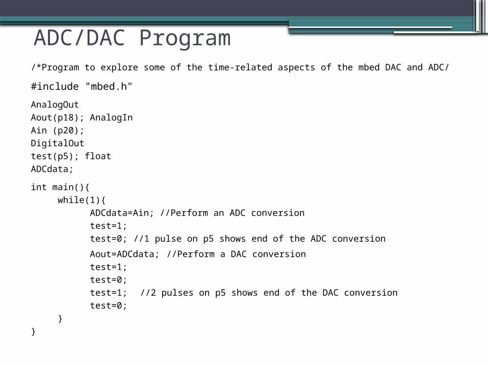
ADC/DAC Program/*Program to explore some of the time-related aspects of the mbed DAC and ADC/
#include "mbed.h"
AnalogOut Aout(p18); AnalogIn Ain (p20); DigitalOut test(p5); float ADCdata;
int main(){ while(1){ ADCdata=Ain; //Perform an ADC conversion test=1; test=0; //1 pulse on p5 shows end of the ADC conversion
Aout=ADCdata; //Perform a DAC conversion test=1; test=0; test=1; //2 pulses on p5 shows end of the DAC conversion test=0; }}

Timing issues and consequences
Single pulse Single pulseDouble pulse Double pulse
DACconversio
n ADC Conversion
DACconversio
n

Switching an digital output on or off takes ~72 ns cf 1 clock period = 1/96 MHz = 10.4 ns
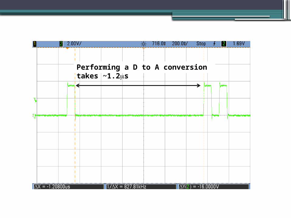
Performing a D to A conversion takes ~1.2s

Performing A to D conversion
takes~22 s

Sampling rate/*Program to explore some of the time-related aspects of the mbed DAC and ADC/
#include "mbed.h"
AnalogOut Aout(p18); AnalogIn Ain (p20); DigitalOut test(p5); float ADCdata;
int main(){ while(1){ ADCdata=Ain; //Perform an ADC conversion test=1; test=0; //1 pulse on p5 shows end of the ADC conversion
Aout=ADCdata; //Perform a DAC conversion test=1; test=0; test=1; //2 pulses on p5 shows end of the DAC conversion test=0;
wait (0.001) // slows sampling rate }}

wait = 1msMaximum frequency < 500 Hz
Ain = 200 Hz
Ain = 400 Hz
Ain = 500 Hz
Ain = 976 Hz

wait = 0 ms. What is Nyquist frequency ?
Looks ~ 44 kHz.Standard audio CDs are sampled at played back at 44.1 kHz, to adhere to Nyquist sampling criteria as it relates to human auditory system which extends to ~ 20 kHz. Coincidence?

Some DAC and ADC timing issues and consequences
This is a bit strange, as from the LPC1768 UserManual Table 531, A/D Control Register
This is the price we are paying for the ease of programming the mbed using the C++ functions.