an investigation of the transient thermal analysis of spur gears
TRANSCRIPT

N . S 4 - 2 8 G 8 8 .NASA Technical Memorandum 83724
An Investigation of the TransientThermal Analysis of Spur Gears
Lotfi E. El-Bayoumy and Lee S. AkinCalifornia State University at Long BeachLong Beach, California
and
Dennis P. TownsendLewis Research CenterCleveland, Ohio
Prepared for theFourth International Power Transmission and Gearing Conferencesponsored by the American Society of Mechanical EngineersCambridge, Massachusetts, October 10-12, 1984
NASA
https://ntrs.nasa.gov/search.jsp?R=19840020019 2018-02-07T06:05:28+00:00Z

AN INVESTIGATION OF THE TRANSIENT THERMAL ANALYSIS OF SPUR GEARS
Lotfl E. El-Bayoumy and Lee S. AkinCalifornia State University at Long Beach
Long Beach, California
and
Dennis P. TownsendNational Aeronautics and Space Administration
Lewis Research CenterCleveland, Ohio 44135
ABSTRACT
A finite element computer program has been developed for evaluating the
transient behavior of surface temperature 1n high performance spur gears. The
program 1s an extension of a previously developed code that was limited to
steady state behavior. The time dimension 1s Implemented using two and three
point finite difference schemes. The different schemes are provided to the
<* user for the purpose of numerical stability and convergence studies. A de-™̂iCN
w tailed explanation of the gear cooling process leading to the establishment of
a modified Blok model 1s also Included. Other conventional models for approxi-
mating the heat transfer coefficients are available for comparison. Prelimi-
nary results are given showing snap shots of gear temperature contours at the
Initial stages of tooth engagement.
INTRODUCTION
Amongst the three modes of gear failure, scoring 1s known to be the most
troublesome 1n high speed case hardened gearing. Experimental evidence [1] has
shown that a sudden surge of the flash temperature of the gear takes place at
the onset of scoring. Because of the Interdependence of the flash and bulk
temperatures of the gear, an accurate prediction of the latter 1s highly desir-
able. Recently 1n Refs. 1 to 3 a finite element approach has been successfully

applied to the estimation of bulk temperatures of a pair of meshing gears at
steady state operation. The temperature distribution within each tooth 1s
assumed to be Identical and all transient effects are neglected. A variety of
models were used to approximate the convectlve heat transfer coefficients with-
in the elastohydrodyanmlc film attached to the tooth profile. The effects of
oil Jet cooling and oil Jet Impingement depth were Included 1n Refs. 1 and 3.
Because of the highly transient nature of thermal behavior at the onset of
scoring a transient thermal analysis of the meshing gears would be extremely
useful. Furthermore since the heat transfer coefficients, as will be shown 1n
the text, are themselves time dependent functions, a steady state approach
could not be used without major averaging approximations.
The Intent of this paper 1s to describe a computer analysis procedure for
the transient thermal analysis of spur gears using the finite element method.
The finite element equations are derived using the well known Galerkln or
weighted residual approach as explained 1n detail 1n Ref. 4. The heat flux
Input generated due to friction between the meshing gears 1s derived as a time
dependent function unlike the heat flux used 1n the steady state solutions of
Refs. 1 to 3. Two separate models have been programmed Into the computer code
for approximating the convectlve heat transfer process within the cooling film.
The first allows the use of fixed heat transfer coefficients along the various
sections of the gear profile as 1n Refs. 1 to 3 for the purpose of comparison
with the steady state solution obtained therein. The second uses an array of
time dependent heat transfer coefficients based on an asymptotic solution to
the one-dimensional heat transfer equation as shown 1n the text.

Derivation of Finite Element Equations for Transient Heat Transfer 1n Gearing
It 1s shown 1n Ref. 3 that the majority of heat dissipation occurs at the
tooth boundary. Therefore at the expense of little loss 1n accuracy, 1t can
be assumed that the temperature within one tooth 1s Independent of those within
the neighboring teeth. This justifies the use of the one tooth sector model
shown 1n F1g. 1, Instead of the whole gear.
The partial differential equation governing heat transfer within the Iden-
tified region 1s given by
where
•fryca - \-r-l (2)
= R * R ' F / 20 0
k Pd <T - Vqav
T Current gear temperature, °C (°F)
T Initial gear temperature, °C (°F)a2 2o Gear d1ffus1v1ty, m /sec (1n. /sec)
c Specific heat of gear material, J/kg °K (Btu/lb °F)
k Thermal conductivity of gear material, W/m °K (Btu/ft °F)
RQ Outside radius of gear, m (ft)
F Face width of gear, m (ft)
q Average heat flux through the gear profile, W/hr (Btu/hr)a V
The associated boundary conditions are

36 ht (S' t} R0~. * ~L— k - ~ e - PdRo 0* - ° on f1an
ae ht (s* t} Ro*= + -* — r - * e = 0 on r. (3)an K *
ae hs
where
nn s;n normal coordinate to the tooth profile
2h. convectlve heat transfer coefficient 1n tooth profile, W/hr-m °K
(Btu/hr ft2 °F)
h convectlve heat transfer coefficient on front and back faces of gear
p. diametral pitch of gear, m~ (1n.~ )
q*
r. tooth Involute boundary, loaded side
r. tooth Involute boundary, coast sidet . • N
r front and back end faces of tooth
Discretization 1n the space domain 1s accomplished through the use of the
Galerkln approach [4] 1n conjunction with the trial function.
6(x, y, z, t) = I lyx, y, z) e^t) = N e (4)
where N. are the spatial shape functions chosen as [2]
The Galerkln principle yields the following first order equation
•
C 6 + H 6 + P = 0 (6)

where
6 . I ( H, P Nj d Q dz
•'-I •'-n
f 'T N1 7NJJd * dz -e
N1 a"re
,dr (7)
P1 = - f N1 q drJ e
a =
p = ~T
h.R
v2k on r
Proceedings 1n the manner described by Z1enk1ew1cz [4] for discretization 1n
the time domain such that
e(t) * e(t) = e1 (8)
where L.(t) are time dependent shape functions and $. represents $ at
node n the time dimension. These are given as
Ln - ] - «0 < 5 < 1 (9)
where
5 = t/«t
Applying the Galerkln principle to Eq. (6) by Integrating Its weighted average
over a time element, 1t follows that

«j [£ (en Ln * entl Ln+1) * H (en Ln * en+1 Ln+1) * P] d* = 0 (10)
where W. 1s any appropriately chosen weighting function of time (e).
Noting the definitions of L and L . 1n Eq. (9), the following recur-
rence relation for $ Is obtained.*n
(C/At + H Y) en+1 = [c/At - H(i - Y)] en + £ (ii)
where
Y = / W.J J
P = / W. P d^// W, d^~ Jn J ~ ^n J
(12)
'0
If a shape function expansion similar to Eq. (8) 1s used to express the heat
Input term P, the last of Eq. (12) becomes
A variety of numerical schemes such as the Euler, Crank-Nicholson, backward
difference etc. are the results of Eq. (11) for various assumptions of the
weighting function W. (see [4] for details). It can be shown that 0 < Y < 1J
and that for numerical stability Y > 1/2.
Derivation of Time Dependent Fr1ct1onal Heat Input
The steady-state heat flux Input generated 1n friction between the two
meshing gears was derived 1n [1] as:
2J
1 1 ~Nl ( A'1 \ (13)2
where the subscript 1 refers to the Instantaneous point of contact along the
tooth profile. Because the analysis 1n [1] was restricted to steady state
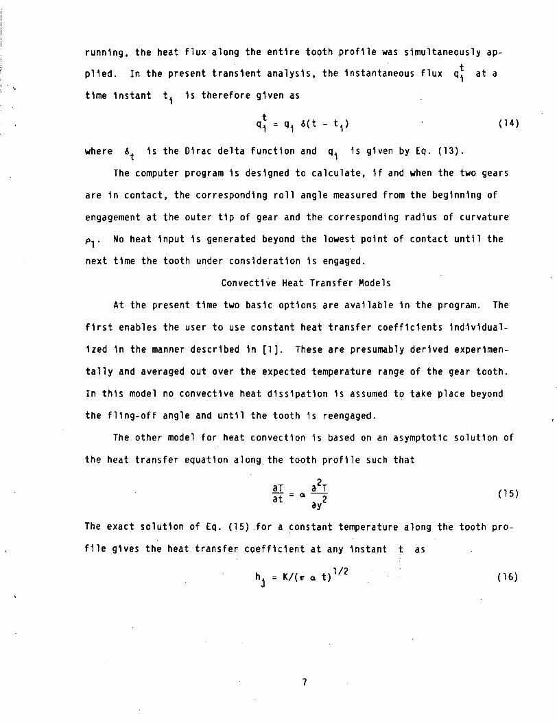
running, the heat flux along the entire tooth profile was simultaneously ap-
plied. In the present transient analysis, the Instantaneous flux q. at a
time Instant t. 1s therefore given as
q* = QI i(t - t,) (14)
where 6. 1s the D1rac delta function and q, 1s given by Eq. (13).
The computer program 1s designed to calculate, 1f and when the two gears
are 1n contact, the corresponding roll angle measured from the beginning of
engagement at the outer tip of gear and the corresponding radius of curvature
PI. No heat Input 1s generated beyond the lowest point of contact until the
next time the tooth under consideration 1s engaged.
Convectlve Heat Transfer Models
At the present time two basic options are available 1n the program. The
first enables the user to use constant heat transfer coefficients Individual-
ized 1n the manner described 1n [1]. These are presumably derived experimen-
tally and averaged out over the expected temperature range of the gear tooth.
In this model no convectlve heat dissipation 1s assumed to take place beyond
the fling-off angle and until the tooth 1s reengaged.
The other model for heat convection 1s based on an asymptotic solution of
the heat transfer equation along the tooth profile such that
3T 32T ,,,..if--^5 < 1 5>
The exact solution of Eq. (15) for a constant temperature along the tooth pro-
file gives the heat transfer coefficient at any Instant t as
h, = K/(ir a t)1/2 (16)

where K 1s the thermal conductivity of the oil. Again 1n this model no heat
dissipation 1s assumed to take place beyond the fling off angle and until the
tooth 1s reengaged.
The amount of heat flux dissipated 1n convection 1s given by
qQ = hA AT (17)
where h may be assigned fixed values, while the tooth Is being cooled, or the
program 1s Instructed to calculate the current value of h from Eq. (16).
RESULTS AND DISCUSSION
The recurrence formula of Eq. (11) above constitutes a set of nonhomoge-
neous algebraic equations for the dlmenslonless temperature array 6 , at a***n +1
time node n+1 1n terms of the temperature array 6 at the preceding time~n
node n and the dlmenslonless heat flux array P. It should be noted that the
latter 1s made of a linear combination of the heat fluxes at times n and
n+1, as defined 1n Eq. (13). Based on recommendations of well known finite
element programs such as NASTRAN [5] the weighting factor y. convectlonally
known as a finite difference parameter,, 1s assigned a value of 0.55. This
value has been found to yield rapid convergence and greater accuracy for prob-
lems with known exact solutions. The computational technique consists of a
standard Initial value problem algorithm 1n which the Initial temperatures are
assumed and heat flux vector 1s computed from Eqs. (14) and (15). A Cholesky
decomposition 1s then administered to Eq. (11) to facilitate the solution [6].
The finite element grid used for computation 1s shown 1n F1g. 2 In which
the tooth 1s divided Into 18 layers of triangular elements using the gear fi-
nite element generator program ATOGEN. It was shown 1n Ref.3 that In the
steady state case, this mesh yielded results of sufficient accuracy. The
example run 1s that of the NASA four square testing apparatus described 1n
Ref. 1.

The temperature distribution within the tooth 1s conveniently represented
1n the computer output 1n the form of constant contour lines as Illustrated 1n
F1gs. 3 to 7. Each figure represents a chronological set of "snap shots" for
the pinion tooth as 1t traverses the line of action between the highest and
lowest points of contact.
All the computer runs were made using an 8 pitch 8.89 cm (3.5 In.) pitch
diameter, 0.635 cm (0.25 1n.) wide spur gear operating at 10 000 rpm with a
normal load of 5912 N/cm (3378 lb/1n.) and a dlmenslonless oil Jet Impingement
depth of 0.336.
In F1gs. 3(a) to (d) (Case 1) the heat transfer coefficients for the dif-
ferent regions of the gear tooth model (fig. 1) are assumed constant during the
period of contact and their values are Identical with those used In Refs. 1 and
3 for the steady state temperature survey of the subject gear and were H = 0.6
for the sides of the tooth, H. = 3.0 for the tooth flank surfaces without oil
Jet cooling, H. = 13 for tooth flank surface with oil Jet cooling and H.^ = 3.0
for top land of tooth with oil Jet cooling. As noted 1n Ref. 1, those values
were obtained 1n an Iterative manner to yield best correlation with test data.
The temperature contours are seen to be crowded around the point of con-
tact, a would be expected, since the heat source at that Instant of time coin-
cides with that point. .The maximum temperature at any Instant during the mesh
cycle always occurs at the Instantaneous point of contact. The contours pro-
ceed to propagate and spread out down the tooth profile. It 1s Interesting to
note that closed loop contours are occasionally observed within the gear tooth
Indicating the presence of local maxima 1n the thermal topology of the tooth.
These contours continue to propagate away from the contact point towards the
unloaded coast side until they totally disappear.

The temperature contours at the same Instants of time are reproduced 1n
F1gs. 4(a) to (d) (Case 2) using a heat transfer coefficient h. obtained from
the time dependent Eq. (16). Gear cooling 1s constrained to the loaded side of
the tooth above the lowest point of contact. The Initial distribution of tem-
perature 1s significantly different from the preceding case for the recess por-
tion of contact, up to the pitch point, where the distribution approaches the
case of steady heat transfer coefficients. In fact the maximum temperature
rise during the contact period 1s nearly the same for the two cases (14.18° C
for case 1 versus 14.11° C for case 2).
Case 3 (figs. 5(a) to (d)) plots pertain to cooling of the top land 1n
addition to the loaded portion of the tooth. Comparison of F1g. 5 with F1g. 4
Indicates no significant change with the additional cooling from the top land.
One may therefore suggest that cooling the top land 1s of little or no benefit
1n reducing the bulk temperature of the gear. More study 1s required before
this will be conclusive. The maximum temperature rise during the first engage-
ment cycle for this case 1s found to be 14.03° C.
The remaining two cases consider the addition of cooling to the coast side
of the tooth as well as the transverse planes of the gear. Because the tran-
sient heat transfer formula, Eq. (16) 1s Independent of temperature (except
Implicitly through the thermal conductivity k and d1ffus1v1ty a), the In-
stantaneous heat transfer coefficients used for all regions of the tooth are
Identical. Although this 1s far removed from practice, 1t 1s Interesting to
note the significant drop 1n temperature as a result of cooling the ends and
coast sides of the tooth. The maximum temperature rise 1s only a fraction of
that computed for cases 1 to 3. The temperature contours are now continuously
crowded around the contact point with most of the tooth remaining at the Ini-
tial temperature.
10

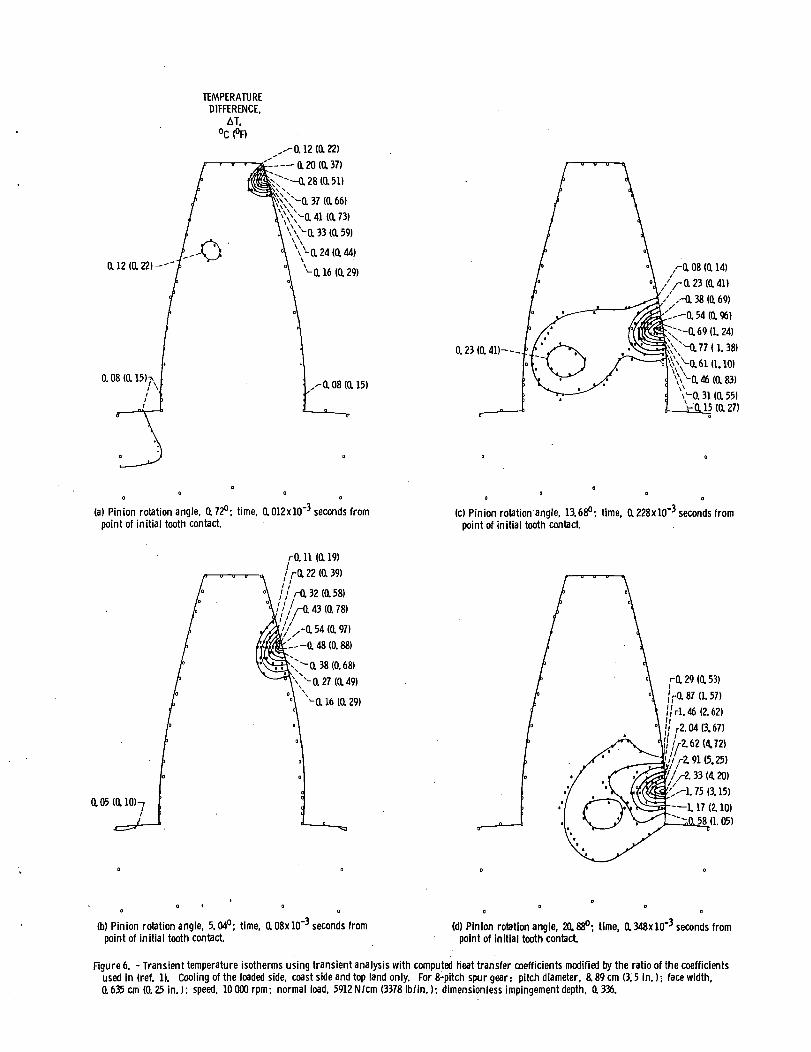
An attempt was made to modify the heat transfer coefficients by multiply-
ing them by a correction factor proportional to the steady state heat transfer
coefficients, I.e., H x.6/13, H. x 3/13, Hn x 13/13 and H.. x 3/13. The re-S L J J L
suiting contour plots are not shown 1n this paper because of their similarity
to F1gs. 6 and 7.
The reduction 1n maximum temperature 1s still very significant, although
not as drastic as shown 1n cases 4 and 5 (figs. 6 and 7) (AT max = 6.03° C not
shown versus 2.91° C (fig. 6(d)).
Figure 8 Illustrates how the Instantaneous maximum temperature varies
with time (or pinion rotation angle) such as would be detected In an experi-
mental measurement. Although no experimental results are available at this
time for the Initial stages of engagement, the wavy patterns obtained 1n
F1g. 8 resemble those for the experimental data shown 1n Ref. 1. The minimum
temperature noted 1n the graph 1s clearly associated with the pitch point,
where pure rolling takes place and friction losses are negligible.
SUMMARY OF RESULTS
A finite element computer program has been developed for evaluating the
transient behavior of surface temperature 1n high performance spur gears. The
program 1s an extension of a previously developed code that was limited to
steady state behavior. The time dimension 1s Implemented using two and three
point finite difference schemes. The different schemes are provided to the
user for the purpose of numerical stability and convergence studies. A de-
tailed explanation of the gear cooling process leading to the establishment of
a modified Blok model 1s also Included. The following results were obtained:
(1) The maximum temperature obtained with constant heat transfer coeffi-
cients, used to predict steady state conditions, 1s nearly the same as that
obtained from a time-dependent modified Blok model when heat dissipation 1s
constrained to the loaded side of the tooth.
11

(2) Cooling of the top land was found to be of no benefit 1n reducing
gear temperature.
(3) Cooling of coast side of the tooth was, on the other hand, of great
significance and should be utilized whenever possible.
(4) The temperature rise along the recess portion of the gear tooth 1s
markedly lower than the approach portion. It should be advantageous, there-
fore, to use recess-action type gears to preclude scoring.
ACKNOWLEDGEMENT
The authors would like to thank Dr. John Murdock for deriving the tran-
sient formula of the heat transfer coefficient.
REFERENCES
1. Townsend, D. P., and Akin, L. S., "Analytical and Experimental Spur Gear
Tooth Temperature as Affected by Operating Variables," Journal of
Mechanical Design. Vol. 13, No. 4, Jan. 1981, pp. 219-226.
2. Patlr, N., and Cheng, H. S., "Prediction of Bulk Temperature 1n Spur
Gears Based on Finite Element Temperature Analysis," ASLE preprint No.
77-LC-38-2, Oct. 1977.
3. El-Bayoumy, L. E., Akin, L. S., and Townsend, D. P., "Parameter Studies
of Gear Cooling Using an Automatic Finite Element Mesh Generator,"
submitted for presentation at the ASME Fourth Int. Power Trans, and
Gearing Conference, Cambridge, MA, Oct. 1984.
4. A1enk1ew1cz, 0. C., The Finite Element Method. McGraw-Hill, New York,
1977, pp. 569-604.
5. MacNeal, R. H., The Nastran Theoretical Manual. Level 15.5,
MacNeal-Schwendler Corporation, Dec. 1972, pp. 8.4-7 to 8.4-12.
6. Segerllnd, L. J., Applied Finite Element Analysis. Wiley, New York, 1976.
12


TEMPERATURE
DIFFERENCE.AT.
1.27 (2.28)
a 84 (1.52)
0.42(0.76)-.
-422(7.60)
3.80(6.84)
-—3.38(6.08)
^0-2.53(4.56)
(3.80)
1.27 (2.28)
- a 84 (1.52) a 91 (1.64)
1.05 (1.89) -
1.19(2.14)-
1.05(1,89)-
0.9H1.64K
\. 19 (2.14)
1.47 (2.65)
1.75 (3.16)
'^,-£03(3.66)
——3.85(6.93)
1.89(3.41)
'-1.61 (2.90)
"M. 33 (2.40)
^-a 77 (1.39)
(a) Pinion rotation angle, a 72°; time, 0.012xlO~3 seconds frompoint of initial tooth contact
° 0
(c) Pinion rotation angle. 13.68°; time, 0.228xlO"3 seconds frompoint of initial tooth contact
1.77(3.19)-f
1.35 (2.44)^
0.53(0.95HX
x-2.19 (3.94)
,--£60(468)
3.02(5.43)
410 (7.37)
~ ~3.84 (6.92)
^ 3.43 (6.17)
--0.94 (1.70)
v- a 11 (a 20)
3.77(6.78)-'
r 6.08 (10.95)
/-7.24 (13.03)
/ / r*. 40 (15.11)/ /'/f-10.71 (19.28)
\\ 03 (23.45)
18 (25.53)
,-\\. 89 (21.36)
9.55(17.20)
(b) Pinion rotation angle, 5.04°; time, ttOSxlO"3 seconds frompoint of initial tooth contact
(d) Pinion rotation angle, 20.88°; time, a 348x 10"3 seconds frompoint of initial tooth contact
Figure 3. - Transient temperature isotherms using steady state heat transfer coefficients Hs, 0.6; Ht and H:t, 3; H.-. 13. For 8-pitch spur gear: pitch diam-eter, a 89 cm (3.5 in.); face width, a 635 cm (a 25 in.); speed, lOOOOrpm; load. 5912 N/cm (3378 Ib/in.V. dimensionless impingement depth, a 336.

TEMPERATUREDIFFERENCE.
AT,°C (°F)
a 12 (a 221
.- a «i,X.—— a 24 (a 43)' '- 0.32 (a 58)
^-0.4(0.72)
136(0.6!
a 28 (0.51)
0.20 (0.36)
-0.12(0.22)
a 98 (1.76)
a 98 (1.76)
a 67 U.20)-
a 36 (0.64)
a 67 (1.20)-1.29(2.32)
-1.91(3.44)
- 2.53 (4.55)
3.15(5.67)
-2.83(5.11)
-2.22(3.99)
M. 60 (2.88)
(a) Pinion rotation angle, 0.72°: time, 0.012x10"^ seconds frompoint of initial tooth contact
<-0.36 (0.64)
(cl Pinion rotation angle, 13.68°; time, 0.228x 10~3 seconds frompoint of initial tooth contact.
a 48 (a 87)
a 37 (0.66) ;
0.25(0.45K
,-0. 25 (a 45)
//-a37 (0.66)
' ̂ a eo a. os)'-'— 0.84 (1.05)
~ '~—1.070.93)
""-1.1912.14)
^-a 95 (1.72)\
'\^a 72 a. 29)x-a 48 (a 87)
a 13 <a 24)
(b) Pinion rotation angle, 5.04°-, time, a08xlO"3 seconds frompoint of initial tooth contact.
1.67(3.00)—'
3.05(5.49)
443(7.78)-
5.82 (10.47)
^5.82(10.47)
^7. 20 (12. 96)
•' /- 9. 97 (17. 94)
/-12. 73 (22. 91)
Vl4.11(25.41)
a 58 (15. 45)
5.82 (la 47)
(d) Pinion rotation angle, 20.88°-, time, a 348xlO"3 seconds frompoint of initial tooth contact
Figure 4. - Transient temperature isotherms using transient thermal analysis with computed heat transfer coefficients, load side cooling only. For 8-pitchspur gear: pitch diameter, a 89 cm (3.5 in.); face width, 0.635 cm (a 25 in.); speed, 10000 rpm; load, 5912 N/cm (3378 Ib/in.); dimensionless impinge-ment depth, tt 336.

TEMPERATUREDIFFERENCE.
AT,
a 20 (a 37)-.
/- a 33 (0.59)
,-0.37 (tt 67)
;—-0.41(0.73)
a 28 (a si)\>a 24 ta 44)
-a 20 ta 37)
0.32(0.58)--.
0.63(1.14)
/-I. 25 (2.25)
^1.87 (3.36)
2.49 (4. 48)
,--3.10(5.59)
2.80(5.03)
2.18 (3. 92)
. 56 (2.81)
-a 94 (1.69)
(a) Pinion rotation angle, 0.72°; time, 0.012xlO~3 seconds frompoint of initial tooth contact.
(c) Pinion rotation angle. 13.68°; time, Q. 228x 10~3 seconds frompoint of initial tooth contact.
,-0.12(0.22)
,-0.241(0.43)
/HX 47 (0.85)
' 0.71 (1.28)
0.94(1.70)
,-~\. 18 (2.13)
—1.06 (1. 92)
a 83 (1.49)
0.59(1.07)
l 36 (0.64)
(b) Pinion rotation angle, 5.04; time, 108x10" seconds frompoint of initial tooth contact
/-5.67 (10.20)
' ,/-7.06(12.71)
&. 46 (15. 22)
,^11.24(20.24)
,/-140(25.25)
12.64(22.75)
—9.85(17.73)—-K
-7.06(12.71)
(d) Pinion rotation angle, 20,88°; time, a348xlO"3 seconds frompoint of initial tooth contact
Figure 5. - Transient temperature isotherms using transient analysis with computed heat transfer coefficients, load side and top tend cooling only.For 8-pitch spur gear: pitch diameter, 8.89 cm (3.5 in.); face width, a635 cm (a 25 in.); speed, 10000 rpm; load, 5912 N/cm (3378 Ib/in.);dimensionless impingement depth, 0,336.
TEMPERATUREDIFFERENCE,
AT.
a 12 ia 22)--
0.08 (a 15KI \
,^0.12 (a 22)"—-0.20(0.37)
-a 28 ia si)^-0.37(0.66)l'";\Mui«x73)
vXvo.33(o.59)Vv a 24 (0.44)
va 16 (a 29)
/- a oa <a is)
a 23 <a 4i)—~
^0. 08 (a 14)//-a 23 <a 4DV-0.38IO.69)'--a 54 ia 96)
\\Nu7a38)
\\H46 (a 83)'̂ a 3i (a 55)
-JtM5 (tt 27)
(a) Pinion rotation angle, 0.72°; time, 0.012xlO~3 seconds frompoint of initial tooth contact.
(c) Pinion rotation angle, 13.68°; time. 0.228xlO~3 seconds frompoint of initial tooth contact.
rO. 11 (tt 19)
(0.39)
a 05 ta 101-7
/rO. 32 (0.58)
//-a 43 (0.78)
'-—§. 48 (0. 88)
a 38 (0.68)
a 16 (a 29)f-0.29<0.53)
,-0. s? a. 57)ifrl. 46 (2.62)
r2.04(3.67)
' /r2.62(4.72)
//ri91(5.25)
^-2.33(420)
',--\. 75 (3.15)
1.17 (i 10)•8 (1.05)
(b) Pinion rotation angle, 5.04°; time, a OSxlO"3 seconds frompoint of initial tooth contact
(d) Pinion rotation angle, 20.88°; time, a 348xlO"3 seconds frompoint of initial tooth contact
Figure 6. - Transient temperature isotherms using transient analysis with computed heat transfer coefficients modified by the ratio of the coefficientsused in (ref. 1). Cooling of the loaded side, coast side and top land only. For 8-pitch spur gear: pitch diameter, 8.89 cm (3.5 in.) • face width,a 635 cm (0.25 in.); speed, 10000 rpm; normal load, 5912 N/cm (3378 Ib/in.); dimensionless impingement depth, 0.336.

TEMPERATUREDIFFERENCE,
AT,
a 10 (a is)—
a 05 ta 09)7"
.,--0.10(0.18)—a 20 ta 37)Cr—0.30(0.55)
a 41 (0.73)0.51(0.91)
-a 46 <a 82)
V-0.25 (0.46)a is ia z?)
a 09 to. i?)
a 19 <a 34)—--r
r 0.09 (a 17)o.28(0.51)
/Vo . 47 (0.85)
',-—0.85(1.53)~---0.95(1.71)
\VMH38(0.68)V0. 19 (0.34)
(a) Pinion rotation angle, 0.72°; time. 0.012x 10"̂ seconds from-point of initial tooth contact
(c) Pinion rotation angle, 13.68°; time, 0.228xlO"3 seconds frompoint of initial tooth contact
r o. 07 <a 12)rO.2010.36)
/Va 34 (0.61)(0.85)
O, 61 (1.09)-—0.67(1.21)
0.54 (tt 97)-a 40 (0.72)-0.27 (a 49)0.13 (tt 24)
r 0.36 (a 65)/rl. 08 (1.94)
/•I. 80 (3. 24)1 1 1 rt 52 (4 53)////V3.246.83)
i. 88 (5. 18)2.16(3.89)
-—1.44(2.59)--a 72 (1. 30)
(b) Pinion rotation angle, 5.04°; time,. 0.08xlO"3 seconds frompoint of initial tooth contact
(d) Pinion rotation angle, 20.88°; time, 0.348xlO~3 seconds frompoint of initial tooth contact
Figure 7. - Transient temperature isotherms using transient analysis with calculated heat transfer coefficients modified by the ratio of the coefficientsused in (ref. 1). Cooling of the loaded side, coast side, top land and end of the teeth. For 8-pitch spur gear: pitch diameter, 8.89 cm (3.5 in.);face width, a 635 cm (a 25 in.); speed, lOOOOrpm: normal load, 5912N/cm (3378lb/in.l; dimensionless impingement depth, 0,336.

15 i—
10
LEDGER OF COMPUTED POINTS
O STEADY H'sD TRANSIENT H: ONLYA TRANSIENT tf AND Hjt ONLYV TRANSIENT tf, H, ANT) Hit
O TRANSIENT H. Ht. HjtAND HS
5 10 15 20PINION ROTATION ANGLE, deg
I I.1 .2
TIME, msec
.3
—127
18
.4
Figure 8. - Variation of maximum temperature risewith pinion rotation angle and time.

1. Report No.
NASA TM-83724
2. Government Accession No. 3. Recipient's Catalog No.
4. Title and Subtitle 5. Report Date
An Investigation of the Transient Thermal Analysis ofSpur Gears 6. Performing Organization Code
505-40-42
7. Authors)
Lotfi E. El-Bayoumy, Lee S. Akin, andDennis P. Townsend
8. Performing Organization Report No.
E-2192
10. Work Unit No.
9. Performing Organization Name and Address
National Aeronautics and Space AdministrationLewis Research CenterCleveland, Ohio 44135
11. Contract or Grant No.
12. Sponsoring Agency Name and Address
National Aeronautics and Space AdministrationWashington, D.C. 20546
13. Type of Report and Period Covered
Technical Memorandum
14. Sponsoring Agency Code
15. Supplementary Notes
Lotfi E. El-Bayoumy and Lee S. Akin, California State University at Long Beach,Long .Beach, California; Dennis P. Townsend, NASA Lewis Research Center. Preparedfor the Fourth International Power Transmission and Gearing Conference sponsoredby the American Society of Mechanical Engineers, Cambridge, Massachusetts,October 10-12. 1984.
16. Abstract
A finite element computer program has been developed for evaluating the transientbehavior of surface temperature in high performance spur gears. The program isan extension of a previously developed code that was limited to steady state be-havior. The time dimension is implemented using two and three point finite dif-ference schemes. The different schemes are provided to the user for the purposeof numerical stability and convergence studies. A detailed explanation of thegear cooling process leading to the establishment of a modified Blok model isalso included. Other conventional models for approximating the heat transfercoefficients are available for comparison. Preliminary results are given showingsnap shots of gear temperature contours at the initial stages of tooth engagement.
17. Key Words (Suggested by Authors))
Transient; Thermal analysis; Finiteelement; Lubrication; Cooling; Gears;Heat transfer
19. Security Classif. (of this report)
Unclassified
18. Distribution Statement
UnclassifiedSTAR Category
20. Security Classif. (of this page)
Unclassified
- unlimited37
21. No. of pages 22. Price*
*For sale by the National Technical Information Service. Springfield, Virginia 22161

National Aeronautics andSpace Administration
Washington, D.C.20546
Official Business
Penalty for Private Use. $300
SPCCIAL FOURTH CLASS MAILBOOK 111
IMAM.
Pottage and Fees PaidNational Aeronautics andSpace AdministrationNASA-451
IWNSA POSTMASTF.R: If Undtliverahlc (S*rliir> ISMPostil Manual) IV> Nul Krlurn