part 15 spur gears students
DESCRIPTION
designTRANSCRIPT
Design
Prof. Samy J. Ebeid ١
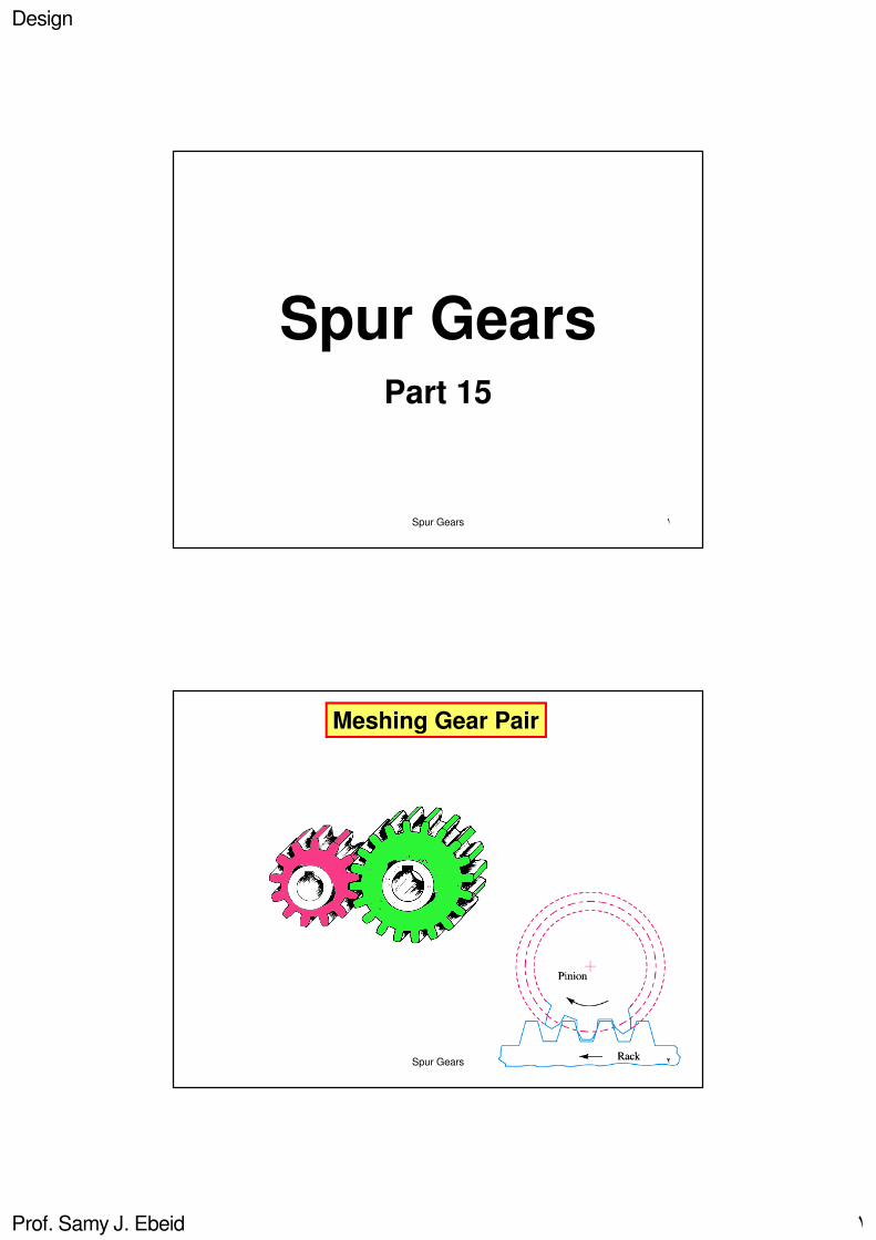
Spur GearsPart 15
١Spur Gears
Meshing Gear Pair
٢Spur Gears

Design
Prof. Samy J. Ebeid ٢
Meshing Gear Pair
Advantages of Gear Drives:
-transmits exact velocity ratio.
-transmits large powers.
-used for short centre distance drives.
-works under high efficiency.
-reliable transmission.
-compact system as compared to belt drives.
Disadvantages of Gear Drives:
-costs much than other drives as special tools are needed.
-subject to noise and vibrations.
٣Spur Gears
Gear Terminology
٤Spur Gears
Parameter Pinion Gear
Number of teeth
Diameter
Module (=d/z)
Addendum
Dedendum
RPM
Design
Prof. Samy J. Ebeid ٣
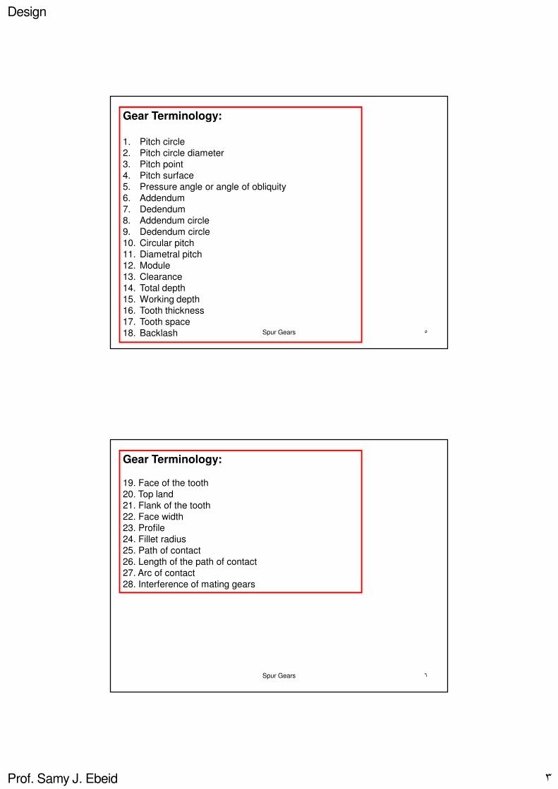
Gear Terminology:
1. Pitch circle
2. Pitch circle diameter
3. Pitch point
4. Pitch surface
5. Pressure angle or angle of obliquity
6. Addendum
7. Dedendum
8. Addendum circle
9. Dedendum circle
10. Circular pitch
11. Diametral pitch
12. Module
13. Clearance
14. Total depth
15. Working depth
16. Tooth thickness
17. Tooth space
18. Backlash ٥Spur Gears
Gear Terminology:
19. Face of the tooth
20. Top land
21. Flank of the tooth
22. Face width
23. Profile
24. Fillet radius
25. Path of contact
26. Length of the path of contact
27. Arc of contact
28. Interference of mating gears
٦Spur Gears

Design
Prof. Samy J. Ebeid ٤
Teeth Interference
Interference is the phenomenon when the tip of a tooth
undercuts the root on its mating gear.
٧Spur Gears
Peripheral Speed & Speed Ratio
100060100060
2211
x
ND
x
NDv
ππ==
2
1
1
2
1
2
N
N
Z
Z
D
Du ===
D2, N2, Z2
٨Spur Gears

Design
Prof. Samy J. Ebeid ٥
Sense of Rotation
Gear B will rotate in an
opposite sense to pinion A
٩Spur Gears
Sense of Rotation of GearsInternal Meshing
Gear B will rotate in
the same sense as pinion A
Gear, D2
C
١٠Spur Gears

Design
Prof. Samy J. Ebeid ٦
The Cycloid Form of Teeth for Spur Gears
The Cycloid curve is the one traced by a point on the circumference of
a circle which rolls without slipping on a fixed straight line.
The EpiCycloid curve is the one traced by a point on the
circumference of a circle which rolls without slipping on the outside of a
fixed circle.
The HypoCycloid curve is the one traced by a point on the
circumference of a circle which rolls without slipping on the inside of a
fixed circle.
١١Spur Gears
C and D are the rolling circles forming the profiles of the cycloidal teeth.
١٢Spur Gears

Design
Prof. Samy J. Ebeid ٧
The Involute Form of Teeth for Spur Gears
The Involute is the curve generated by a point on a
tangent, which rolls on a circle without slipping. This circle
is known as the base circle.
١٣Spur Gears
Strength Calculations for Spur GearsBasic Assumptions
Total stress
The tooth is treated as
a cantilever beam.
The force of interaction can be taken as
being normal to the teeth profiles (i.e.
along the line of action which is tangent to
the base circle). ١٤Spur Gears

Design
Prof. Samy J. Ebeid ٨
Strength Calculations for Spur GearsBasic Assumptions
The force of interaction between a single pair of mating teeth
remains constant in transmitting a constant torque.
The force is applied to the top of the tooth, where the arm of the
force is maximal.
To simplify calculations, the force is moved along the line of action
to the axis of the tooth and is resolved into two components:
1. P * cos α which bends the tooth2. P * sin α which compresses the tooth.
The tooth is treated as a
cantilever beam.
The force of interaction can be
taken as being normal to the
teeth profiles (i.e. along the line
of action which is tangent to the
base circle).
١٥Spur Gears
Strength Calculations for Spur GearsBasic Assumptions
The dangerous cross-section
is at the root of the tooth in
the zone of maximum stress
concentration.
The critical section is one
where fatigue cracks and
failure begins i.e. the tensile
side.
١٦Spur Gears

Design
Prof. Samy J. Ebeid ٩
Strength Calculations for Spur GearsBasic Assumptions
١٧Spur Gears
Strength Calculations for Spur GearsBasic Assumptions
١٨Spur Gears

Design
Prof. Samy J. Ebeid ١٠
Static Bending Strength of TeethModified Lewis Formula
Allowable bending stress Modified form factor Velocity factor
Tangential force Service factor Tooth width Module
mb
sk
vk
yk
bσ
t P =
Assumptions of Lewis:
-Pt acts at the PCD
-Load carried by one tooth
-Load uniformly distributed on tooth
١٩Spur Gears
Static Bending Strength of Teeth
Gear Face Width: b
b/m = 6-10 for cast teeth
10-25 for machined teeth
Velocity: m/s
1-10 slow
10-20 medium
>20 high
Kv = 3 / [3+v] v up to 10 m/s
= 6 / [6+v] v up to 20 m/s
= 5.5 / [5.5+sqrtv] v > 20 m/s
Industrial or commercialMillingSlow
AccurateGrindingMedium
precisionLappingHigh
T {kgcm}=71620 x (HP/N)T {Nm} =9550 x (KW/N)
٢٠Spur Gears

Design
Prof. Samy J. Ebeid ١١
Module Series
٢١Spur Gears
Service Factor
These values are for enclosed well lubricated gears. In case of non-
enclosed and grease gears, the values given in the above table should be
divided by 0.65, i.e. the service factors values will increase.
٢٢Spur Gears
Design
Prof. Samy J. Ebeid ١٢
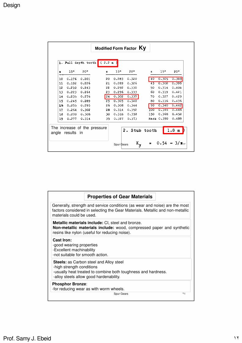
Modified Form Factor Ky
The increase of the pressure
angle results in a stronger
tooth.
٢٣Spur Gears
Properties of Gear Materials
Generally, strength and service conditions (as wear and noise) are the most
factors considered in selecting the Gear Materials. Metallic and non-metallic
materials could be used.
Metallic materials include: CI, steel and bronze.
Non-metallic materials include: wood, compressed paper and synthetic
resins like nylon (useful for reducing noise).
Cast Iron:
-good wearing properties
-Excellent machinability
-not suitable for smooth action.
Steels: as Carbon steel and Alloy steel
-high strength conditions
-usually heat treated to combine both toughness and hardness.
-alloy steels allow good hardenability.
Phosphor Bronze:
-for reducing wear as with worm wheels.٢٤Spur Gears

Design
Prof. Samy J. Ebeid ١٣
Properties of Gear Materials3
σ
1.5
σσ
uy
b ==
٢٥Spur Gears
Properties of Gear Materials
٢٦Spur Gears

Design
Prof. Samy J. Ebeid ١٤
Properties of Gear Materials
٢٧Spur Gears
Properties of Gear Materials
٢٨Spur Gears

Design
Prof. Samy J. Ebeid ١٥
Properties of Gear Materials
BHN
kg/mm²
C%
٢٩Spur Gears
Properties of Gear Materials
yieldkg/mm²
٣٠Spur Gears

Design
Prof. Samy J. Ebeid ١٦
Properties of Gear Materials
UTSkg/mm²
endurancekg/mm²
٣١Spur Gears
Properties of Gear Materials
٣٢Spur Gears

Design
Prof. Samy J. Ebeid ١٧
Dynamic Loading
The Dynamic Load or Impact Load is not anexternal load applied to the system, thus it could betermed: Internal Dynamic Loading.
Due to errors resulting from:-manufacturing and assembly: such errors cause short periods of acceleration and deceleration, which are increased by the elastic deflections of the teeth. -elastic deflection of the teeth under loading
٣٣Spur Gears
Dynamic Loading
We obtain:
-non-uniform rotation of the gear when the pinion rotates at uniform speed.
Thus:-the instantaneous speed ratio is variable
-the average speed ratio is constant
This leads to:
-impact (dynamic) loading on the teeth
Thus the gears operate under:
-vibration
-noise
To minimize probability of Failure in teeth, Lubrication is proposed to:
-reduce friction losses-dissipate the heat generated in the gears-prevent corrosion and abrasion
Due to errors resulting from:-manufacturing and assembly: such errors cause short periods of acceleration and deceleration, which are increased by the elastic deflections of the teeth. -elastic deflection of the teeth under loading
٣٤Spur Gears

Design
Prof. Samy J. Ebeid ١٨
Dynamic Loading
Pd = Pt + ∆∆∆∆Pt
Errors in Tooth Profile:1. Probable error , which results from Manufacturing conditions.2. Permissible error, which depends on Function and is related to speed.
Kd : is due to inaccuracy in machining and tooth vibration.
Kd = (k.e) / ((1/Ep) + (1/Eg))
Where e is the probable error. k =
= 0.107 for 14.5̊ tooth
= 0.111 for 20̊ full depth tooth= 0.115 for 20̊ stub tooth ٣٥Spur Gears
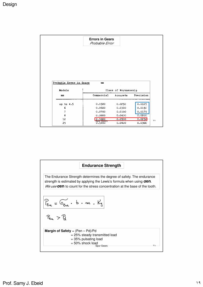
Errors in Gears
Permissible Error
٣٦Spur Gears
Design
Prof. Samy J. Ebeid ١٩
Errors in Gears
Probable Error
٣٧Spur Gears
Endurance Strength
The Endurance Strength determines the degree of safety. The endurance
strength is estimated by applying the Lewis’s formula when using σσσσen.
We use σσσσen to count for the stress concentration at the base of the tooth.
Margin of Safety = (Pen – Pd)/Pd
= 25% steady transmitted load
= 35% pulsating load
= 50% shock load ٣٨Spur Gears
Design
Prof. Samy J. Ebeid ٢٠
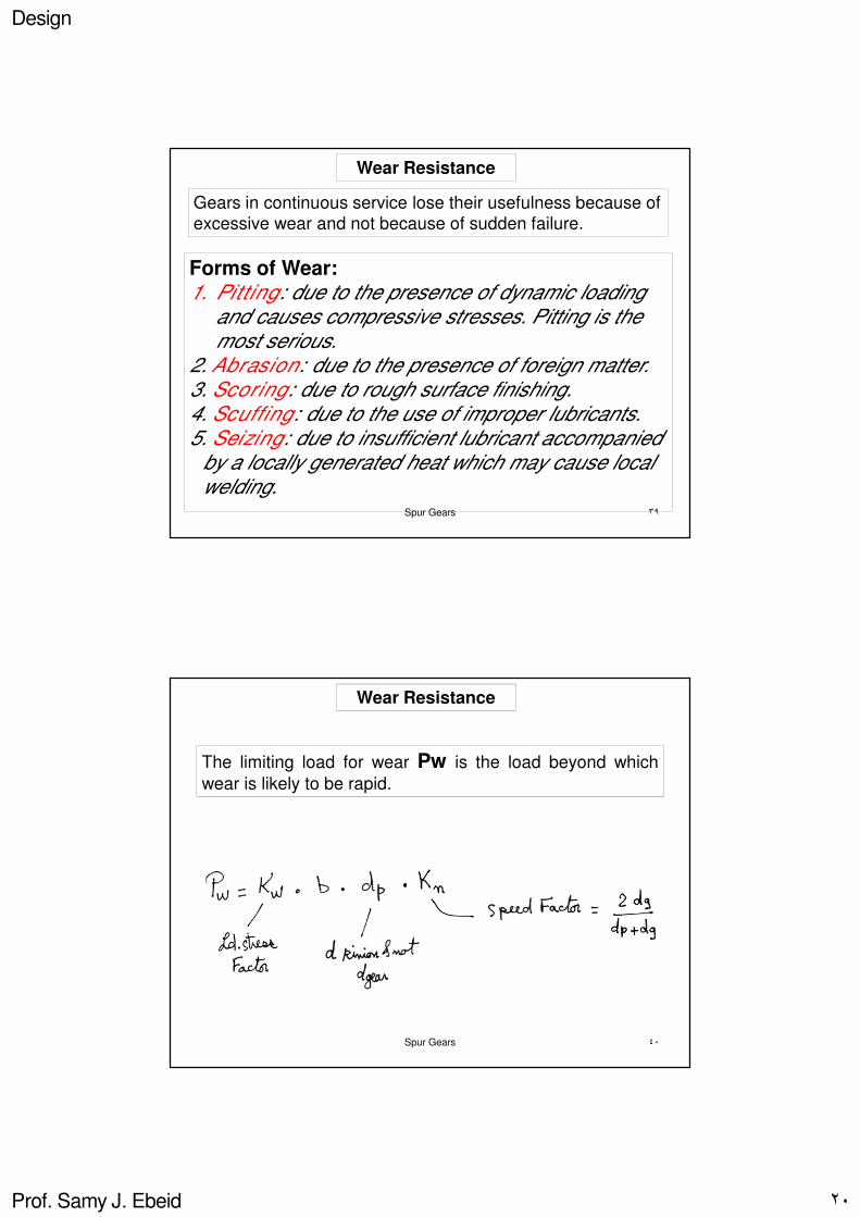
Wear Resistance
Gears in continuous service lose their usefulness because of
excessive wear and not because of sudden failure.
Forms of Wear:1. Pitting: due to the presence of dynamic loading
and causes compressive stresses. Pitting is the most serious.
2. Abrasion: due to the presence of foreign matter.3. Scoring: due to rough surface finishing.4. Scuffing: due to the use of improper lubricants.5. Seizing: due to insufficient lubricant accompanied
by a locally generated heat which may cause local welding.
٣٩Spur Gears
Wear Resistance
The limiting load for wear Pw is the load beyond which
wear is likely to be rapid.
٤٠Spur Gears

Design
Prof. Samy J. Ebeid ٢١
Load Stress Factor kg/sq.mm
٤١Spur Gears
Spur Gear Forces
Fn
Ft
Fr
Driver
Pressure angle
٤٢Spur Gears
Design
Prof. Samy J. Ebeid ٢٢
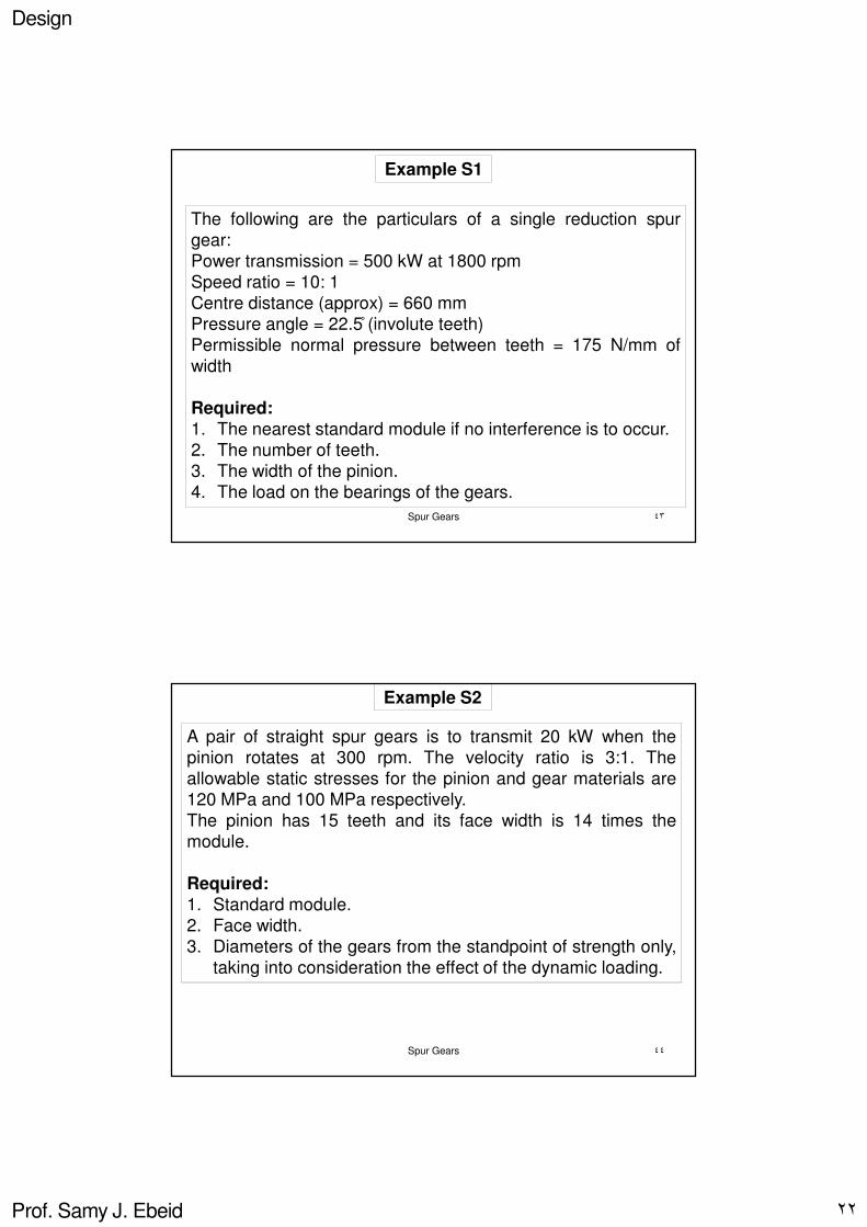
Example S1
The following are the particulars of a single reduction spur
gear:
Power transmission = 500 kW at 1800 rpm
Speed ratio = 10: 1
Centre distance (approx) = 660 mm
Pressure angle = 22.5 ̊ (involute teeth)
Permissible normal pressure between teeth = 175 N/mm of
width
Required:
1. The nearest standard module if no interference is to occur.
2. The number of teeth.
3. The width of the pinion.
4. The load on the bearings of the gears.
٤٣Spur Gears
Example S2
A pair of straight spur gears is to transmit 20 kW when the
pinion rotates at 300 rpm. The velocity ratio is 3:1. The
allowable static stresses for the pinion and gear materials are
120 MPa and 100 MPa respectively.
The pinion has 15 teeth and its face width is 14 times the
module.
Required:1. Standard module.
2. Face width.
3. Diameters of the gears from the standpoint of strength only,
taking into consideration the effect of the dynamic loading.
٤٤Spur Gears

Design
Prof. Samy J. Ebeid ٢٣
Example S3
A gear drive is required to transmit a maximum power of 22.5
kW. The velocity ratio is 2:1 and the speed of the pinion is 200
rpm. The approximate centre distance between the shafts may
be taken as 600 mm. the teeth has 20̊ stub involute profiles.
The static stress for the CI gear material is 60 MPa and the
face width is 10 times the module.
Required:
1. Standard module.
2. Face width.
3. Number of teeth.
Check the design for dynamic and wear loads. The
deformation factor is 80 N/mm and the wear stress factor is
1.4 N/mm2
٤٥Spur Gears
Example S4
A pair of straight teeth spur gears, having 20̊ involute full depth
teeth is to transmit 12 kW at 300 rpm of the pinion. The speed
ratio is 3:1. The allowable static stresses for the CI gear and
the steel pinion are 60 MPa and 105 MPa respectively.
Consider zp = 16 , b = 14m , Kv = 4.5/(4.5+v), Ky = 0.154 –
(0.912/z).
Required:1. Standard module.
2. Face width.
3. Pitch diameters of the gears.
Check the gears for wear, Ep = 200 kN/mm2 and Eg = 100
kN/mm2
٤٦Spur Gears

Design
Prof. Samy J. Ebeid ٢٤
Example S5
A reciprocating compressor is to be connected to anelectric motor through spur gears. The distancebetween the shafts is 500 mm. The speed of theelectric motor is 900 rpm and that of the compressorshaft is 200 rpm. The torque to be transmitted is 5000Nm. Consider the starting torque as 25% more thanthe normal torque.
Required:1. Standard module and face width using 20̊ stub
teeth.2. Number of teeth and pitch circle diameters.
٤٧Spur Gears
Gear Construction
٤٨Spur Gears

Design
Prof. Samy J. Ebeid ٢٥
Gear Construction
٤٩Spur Gears
The cross-section of the arms are usually elliptical, but other forms may be used.
Gear Construction
٥٠Spur Gears

Design
Prof. Samy J. Ebeid ٢٦
٥١Spur Gears