an extension of an algorithm for planar four-bar path generation with
TRANSCRIPT

AN EXTENSION OF AN ALGORITHM FOR PLANAR FOUR-BAR PATHGENERATION WITH OPTIMIZATION
Yahia M. Al-Smadia, Kevin Russellb, Wen-Tzong Leec, Raj S. Sodhida
AECOM Special Structures Group, New York, NY 10005, U.S.A
E-mail: [email protected]
Armaments Engineering and Technology Center, US Army Research, Development and Engineering Center,
Picatinny, NJ 07806, U.S.Ac
Department of Computer Science and Applications, Leader University, Tainan 70970, Taiwand
Department of Mechanical Engineering, New Jersey Institute of Technology, Newark, NJ07102, U.S.A
Received January 2009, Accepted August 2009
No. 09-CSME-03, E.I.C. Accession 3089
ABSTRACT
This work is an extension of the authors’ published work on a planar four-bar motiongeneration search algorithm with Grashof, transmission angle and linkage perimeter conditions[1]. This latest work considers planar four-bar path generation with a coupler point load, crankstatic torque, crank transverse deflection and follower buckling in a modified search algorithm.As demonstrated in the example, a conventional methodology used in kinematic pathgeneration has been expanded to consider static loading, elastic deflection and buckling in pathgeneration. These factors must be considered in mechanical design, but are not the focus intraditional kinematic synthesis.
L’EXTENSION D’UN ALGORITHME DE GENERATION DE TRAJECTOIREOPTIMISE POUR UN QUADRILATERE ARTICULE PLANAIRE
RESUME
L’article est une suite du travail deja publie sur un algorithme de recherche pour la generationde trajectoire pour un quadrilatere articule planaire, base sur la loi Grashof, l’angle detransmission et les conditions de perimetre des liaisons [1]. Ce travail se penche sur la generationde trajectoire avec le chargement d’un point sur la liaison coupleur, la couple statique demanivelle, la deflection transversale de manivelle et le flambage de la liaison suiveur avec unalgorithme de recherche modifie. Une methodologie conventionnelle de generation cinematiquede trajectoire, tel que demontre par un exemple, a ete amelioree en considerant le chargementstatique, la deflection elastique et le flambage. Ces facteurs doivent etre consideres dans laconception mecanique, mais ils ne sont pas le point central dans la synthese cinematiquetraditionnelle.
Transactions of the Canadian Society for Mechanical Engineering, Vol. 33, No. 3, 2009 443

1. INTRODUCTION1.1. Published Works in Synthesis for Rigid-Body Guidance
The synthesis of planar four-bar mechanisms for rigid-body guidance is a well-establishedfield. Recent contributions include the work of Martin et al. [1]. These authors presented asearch and selection algorithm to down-select planar four-bar path generators with respectto Grashof conditions, transmission angle conditions and mechanism perimeter conditions.Yao and Angeles [2] applied the contour method in the approximate synthesis of planarlinkages for rigid-body guidance. By deriving a set of two bivariate polynomial equations andplotting these equations, the real solution to the optimizations (corresponding to theintersections of the contour plots) is determined. Hong and Erdman [3] presented a methodthat is applicable for the synthesis of adjustable four-bar planar and spherical mechanisms.Their work shows that nonadjustable mechanism solutions are special cases of adjustablemechanism solutions. Zhou and Cheung [4] introduced an optimal synthesis method foradjustable four-bar motion generators. A modified genetic algorithm is used to seek theglobal optimal solution of an equation set that includes constraints for fixed pivotpositions, no branch defect, crank existence and link length ratios. Al-Widyan et al. [5]considered the robust synthesis of planar four-bar linkages for motion generation.Danieli et al. [6] applied Burmester theory in the design of planar four-bar motion generatorsto reproduce tibia-femur relative motion. Goehler et al. [7] applied parameterized T1 motiontheory to the synthesis of planar four-bar motion generators. This T1 motion theory isgeneral and not limited to the second order parameterization that is associated with priordevelopment of T1 motion theory. Caracciolo and Trevisani [8] considered rigid-body motioncontrol of flexible four-bar linkages. In their work, a discrete finite element model ofthe four-bar mechanism accounts for geometric and inertial nonlinearities. Zhixing et al. [9]presented a guidance-line rotation method for rigid-body guidance for the synthesisof planar four-bar mechanisms. The method effectively solves the rigid-body guidancesynthesis problem for crank–rocker mechanisms, double-rocker mechanisms anddouble-crank mechanisms for four rigid-body positions and beyond. Lin and Modler [10]presented a method to avoid branch defects, order defects and ensure link rotatability in three-point path generation. The method considers (but is not limited to) planar four-barmechanisms.
Although planar motion and path generation are well-established fields, the concept ofincluding static structural conditions in rigid-body guidance is not nearly as established.With the exception of Huang and Roth [11] whose work includes analytical motion genera-tion models for planar four-bar mechanisms with a prescribed coupler load, most otherworks that investigate the structural behavior of a classical planar four-bar mechanism underload do not consider the structural behavior in the context of motion or path generation. Theworks of Dado [12], Venanzi et al. [13], Sonmez [14], Plaut et al. [15] and Siriam andMruthyunjaya [16] do consider flexible links and/or buckling in mechanism design, but theyconsider the design of compliant mechanisms as opposed to classical planar four-barmechanisms.
1.2. Scope of WorkA coupler load can have a negative effect in path generation since any resulting link
deflections can compromise the accuracy of the precision points achieved by the mechanism.This work presents a nonlinear optimization problem and improved search algorithm to
Transactions of the Canadian Society for Mechanical Engineering, Vol. 33, No. 3, 2009 444

synthesize planar four-bar path generators with constraints for static loading and link elasticity.The specific constraints included consider static torque of the crank, transverse deflection of thecrank and buckling of the follower.
2. PLANAR FOUR-BAR PATH GENERATION
The objective in planar four-bar path generation is to calculate the mechanism dimensionsrequired to achieve or approximate a set of prescribed coupler path points. Figure 1a includesfive prescribed coupler path points defined by the x and y-coordinates of the coupler pointvariable p and the coupler displacement angle variable a1i. Figure 1b includes the mechanismfixed pivot variables a0 and b0 and moving pivot variables a1 and b1. The X and Y-coordinatesof the fixed and moving pivot variables are the mechanism dimensions to be calculated in pathgeneration.
The planar four-bar path generation model presented by Suh and Radcliffe [17] is expressedas
D1i½ �a1{a0ð ÞT D1i½ �a1{a0ð Þ{ a1{a0ð ÞT a1{a0ð Þ~0 (1)
D1i½ �b1{b0ð ÞT D1i½ �b1{b0ð Þ{ b1{b0ð ÞT b1{b0ð Þ~0 (2)
where
D1i½ �~cos a1i { sin a1i pix{p1x cos a1izp1y sin a1i
sin a1i cos a1i piy{p1x sin a1i{p1y cos a1i
0 0 1
24
35: (i~2, 3, 4, 5) (3)
Equation (1) and (2) ensure the constant lengths of the crank and follower links. Equation (3) isa planar coupler displacement matrix. In Equation (3) variables p1 and pi denote a coupler pathpoint in the starting and displaced locations respectively and variable a1i denotes the couplerangular displacement from orientation 1 to orientation i. Because coupler point accuracy is the
Fig. 1. (a) Prescribed coupler parameters and (b) calculated planar four-bar mechanism.
Transactions of the Canadian Society for Mechanical Engineering, Vol. 33, No. 3, 2009 445

focus in path generation, the accuracy of the orientation angles approximated by thesynthesized mechanism is not critical.
When using this mechanism synthesis model to calculate the components of a0, a1, b0 and b1
(where a05[a0x, a0y, 1]T, a15[a1x, a1y, 1]T, b05[b0x, b0y, 1]T and b15[b1x, b1y, 1]T), the user canspecify a maximum of five coupler path points.
3. PLANAR FOUR-BAR MECHANISM UNDER A COUPLER LOAD
Figure 2 illustrates a statically-loaded planar four-bar mechanism. A load (vector F)is applied to the coupler link at p. To achieve static equilibrium under the coupler load F,the rotational degree of freedom of the crank fixed pivot (pivot a0) is constrained.By constraining the rotational degree of freedom of a0, this end of link a0a1
��! becomes afixed end (as indicated by the ground fixed end symbol in Figure 2). An analytical modelto calculate the deflections (vector U) at any element node on this mechanism is formulatedusing
Ff g~ Kglobal
� �Uf g (4)
where the 15x15 global stiffness matrix Kglobal
� �for the mechanism is comprised of
Kj
� �~ Ttransj
� �kj
� �Ttransj
� �{1(5)
-the element stiffness matrix for each mechanism link. In this model, the crank (link a0a1��!) and
coupler (link a1p�! and pb1�!
) are represented by beam elements. Beam elements support X and Y-deflections and Z-rotations [18]. The follower (link b0b1
��!) is represented by a truss member.
Truss members support columnar deflections only [19]. The element stiffness matrix for thecrank and coupler is
Fig. 2. Statically-loaded planar four-bar mechanism.
Transactions of the Canadian Society for Mechanical Engineering, Vol. 33, No. 3, 2009 446

kj
� �~
AjEj
Lj
0 0 {AjEj
Lj
0 0
012EjI j
Lj3
6EjI j
Lj2
0 {12EjI j
Lj3
6EjI j
Lj2
06EjI j
Lj2
4EjI j
Lj
0 {6EjI j
Lj2
2EjI j
Lj
{AjEj
Lj0 0
AjEj
Lj
0 0
0 {12EjI j
Lj3
{6EjI j
Lj2
012EjI j
Lj3
{6EjI j
Lj2
06EjI j
Lj2
2EjI j
Lj
0 {6EjI j
Lj2
4EjI j
Lj
266666666666666666664
377777777777777777775
: (6)
Because the follower is a two-force member (and therefore under columnar loading only) itselement stiffness matrix is
kaxial½ �~
A4E4
L40 0 { A4E4
L40 0
0 0 0 0 0 0
0 0 0 0 0 0
{ A4E4L4
0 0A4E4
L40 0
0 0 0 0 0 0
0 0 0 0 0 0
26666666664
37777777775
(7)
The element local-to-global coordinate frame transformation matrix is
Ttransj
� �~
coshj sinhj 0 0 0 0
{sinhj coshj 0 0 0 0
0 0 1 0 0 0
0 0 0 coshj sinhj 0
0 0 0 {sinhj coshj 0
0 0 0 0 0 1
26666664
37777775: (8)
Vector U includes the global X and Y-deflections and Z rotations for a0, a1, p1, b1 and b0
(Figure 2). Because there are no global X or Y-displacements for the fixed pivots or global Z-rotations for the crank fixed pivot, these components are set to zero (a0x5a0y5a0h5b0x5
b0y50). The remaining component variables are calculated from the analytical four-barmechanism deflection model.
In Figure 2 variables Ej, Aj, Ij and Lj (where j51,2,3,4) are the modulus of elasticity, cross-sectional area, moment of inertia and length of each link respectively. Because the coupler is tobe a member that is uniformly rigid in this work, E25E3, A25A3, I25I3 and its modulus ofelasticity will be prescribed substantially higher (in this work, one million times higher) thanthose of the crank and follower. The angular orientation of each link (using the positive X-axisas reference) is denoted by angle hj (where j51,2,3,4). These angles are used in Equation (8).
Equation (6) is the general stiffness matrix for beam and frame elements [18]. Each elementhas two nodes with three degrees of freedom per node. The first row and column in Equation (6)
Transactions of the Canadian Society for Mechanical Engineering, Vol. 33, No. 3, 2009 447
correspond to the longitudinal displacements of both element nodes relative to the local elementcoordinate system (Figure 2). The second and third rows and columns correspond to the lateraldisplacements and rotations of both element nodes respectively. As nodal constraints areimposed, the general stiffness matrix includes more zero cells. For example, because thefollower link of the mechanism as constrained in Figure 2 undergoes columnar loading only, itsstiffness matrix (Equation (7)) only allows longitudinal displacements.
4. STATIC TORQUE CONSTRAINT OF THE CRANK LINK
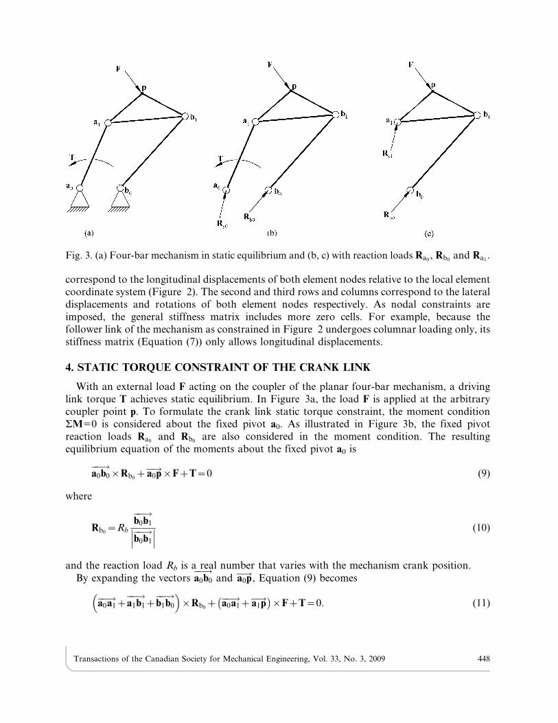
With an external load F acting on the coupler of the planar four-bar mechanism, a drivinglink torque T achieves static equilibrium. In Figure 3a, the load F is applied at the arbitrarycoupler point p. To formulate the crank link static torque constraint, the moment conditionSM50 is considered about the fixed pivot a0. As illustrated in Figure 3b, the fixed pivotreaction loads Ra0
and Rb0are also considered in the moment condition. The resulting
equilibrium equation of the moments about the fixed pivot a0 is
a0b0��!
|Rb0za0p�!|FzT~0 (9)
where
Rb0~Rb
b0b1��!b0b1��!��� ��� (10)
and the reaction load Rb is a real number that varies with the mechanism crank position.
By expanding the vectors a0b0��!
and a0p�!, Equation (9) becomes
a0a1��!za1b1
��!zb1b0��!� �
|Rb0z a0a1��!za1p�!� �
|FzT~0: (11)
Fig. 3. (a) Four-bar mechanism in static equilibrium and (b, c) with reaction loads Ra0, Rb0
and Ra1.
Transactions of the Canadian Society for Mechanical Engineering, Vol. 33, No. 3, 2009 448

Because link b0b1 is a two-force member, vectors Rb0and b0b1
��!are collinear and subsequently
result in a zero cross product. As a result Equation (11) is simplified as
a0a1��!za1b1
��!� �|Rb0
z a0a1��!za1p�!� �
|FzT~0: (12)
Next, the moment condition SM50 is considered about the moving pivot a1 considering allof the links and joints to the right of a1. As illustrated in Figure 3c, the fixed pivot reactionloads Ra1
and Rb0are also considered in the moment condition. The resulting equilibrium
equation of the moments about the moving pivot a1 is
a1b1��!
|Rb0za1p�!|F~0: (13)
Substituting Equation (13) into Equation (12) produces
a0a1��!|Rb0
za0a1��!|FzT~0: (14)
Substituting Equation (10) into Equation (13) and (14) produces
Rb
b0b1��!��� ��� a1b1
��!|b0b1��!
~F|a1p�! (15)
and
Rb
b0b1��!��� ��� a0a1
��!|b0b1��!
~F|a0a1��!{T: (16)
Combining Equation (15) and (16) produces
T~F|a1p�!� �
3
a1b1��!
|b0b1��!� �
3
b0b1��!
zF
0B@
1CA|a0a1
��! (17)
where
F~
fx
fy
0
0@
1A; T~
0
0
ti
0@
1A; a1p�!~pi{ D1i½ �a1; a0a1
��!~ D1i½ �a1{a0; b0b1��!
~ D1i½ �b1{b0; and
a1b1��!
~ D1i½ � b1{a1ð Þ. In Equation (17) the terms F|a1p�!� �3
and a1b1��!
|b0b1��!� �
3are the third
elements of the corresponding vectors. Equation (17) calculates the four-bar mechanism crankstatic torque for a given coupler load. Expressing Equation (17) as an inequality constraint tolimit the maximum crank static torque for N prescribed coupler path points yields
Tið ÞT Tið Þvtmax2: i~1, 2, 3, ::: , N (18)
Equation (18) is the four-bar path generator static torque constraint for the crank link.
Transactions of the Canadian Society for Mechanical Engineering, Vol. 33, No. 3, 2009 449

5. FOLLOWER BUCKLING AND CRANK ELASTIC DEFLECTION CONSTRAINTS
As previously noted, the follower link is under columnar loading only because it is a two-forcemember. The Euler formula for critical buckling load for a column with pinned ends [18] is
Pcr~p2EI
L2: (19)
Johnson’s critical buckling load formula [18] for the same system is
Pcr~sy A-syA2L2
4p2EI
(20)
where variables E, I and L are the modulus of elasticity, moment of inertia and effective columnlength respectively. In Equation (20) variables A and sy are the column cross-section area andmaterial yield stress respectively. Solving for the columnar load in the follower link (Rb) fromEquation (15) yields
Rb~F|a1p�!�� ��
a1b1��!
| b0b1��!b0b1j j
��������: (21)
Expressing Equation (2) as an inequality constraint to prevent follower buckling for N
prescribed coupler path points yields
D1i½ �b1{b0ð ÞT D1i½ �b1{b0ð Þv p2EI
Rb
i~1, 2, 3, ::: , N (22)
where the right-side quantity in this inequality is derived from Equation (19). Being a constantlength constraint, Equation (22) does not calculate the follower buckling load. This equationprevents follower from reaching a buckling length when under the follower columnar load Rb.
Unlike the follower, the crank link is not a two-force member. As shown in Figure 2, thecrank link is a fixed-end cantilevered beam under a transverse load that varies with crankposition. The static torque applied to the crank at a0 (Figure 3a and 3b) and the crank reactionload at a1 due to F (Figure 3c) result in the transversely-loaded, cantilevered beam state of thecrank. Because the constraint and loading conditions on the crank link make crank deflection acommon occurrence, constraining the deflection of the crank is the primary concern. In thiswork, the buckling of link a0a1
��! is not explicitly considered because the link stiffness required tolimit transverse deflection is generally sufficient in avoiding link buckling (especially as thespecified maximum transverse deflection becomes smaller).
The Euler formula for the deflection of a fixed-end cantilevered beam [18] is
d~PL3
3EI(23)
where variables P, L, E and I are the free-end transverse load, beam length, modulus ofelasticity and moment of inertia respectively. From Equation (17), the total load on the movingpivot of the crank link (a1) is
Transactions of the Canadian Society for Mechanical Engineering, Vol. 33, No. 3, 2009 450

Ra�!
~F|a1p�!�� ��
a1b1��!
|b0b1��!��� ��� b0b1
��!zF
0B@
1CA (24)
The transverse component of the crank load is
Ratrans
���!~
F|a1p�!�� ��a1b1��!
|b0b1��!��� ��� b0b1
��!zF
0B@
1CA|
a0a1��!a0a1��!�� �� (25)
Expressing Equation (1) as an inequality constraint to limit crank deflection for N prescribedcoupler path points yields
D1i½ �a1{a0ð ÞT D1i½ �a1{a0ð Þv 3dEI
Ratrans
���!��� ���
0B@
1CA
23
i~1, 2, 3, ::: , N (26)
where the right-side quantity in this inequality is derived from Equation. (22).
6. MODELING CONDITIONS AND ASSUMPTIONS
Because the mechanism of focus in this work is the planar four-bar mechanism only in-planedeflections are considered in the four-bar mechanism deflection model, crank deflectionconstraint and follower buckling constraint. The coupler link is assumed to be exceedingly morestructurally sound than the crank and follower links, and as a result, is assumed to be a non-deforming or ‘‘rigid’’ member. When specifying a modulus of elasticity for the coupler link inthe four-bar mechanism deflection model (Section 3), it is prescribed a value that is 1 milliontimes higher that the modulus for the crank and follower to make its members virtually non-deforming. Also, this work only considers a force at a single coupler point. Because the systemis static and the coupler point load is assumed to exceed the link body forces, these forces areneglected (massless links assumed).
7. PATH GENERATION NONLINEAR OPTIMIZATION PROBLEM
Formulating Equation (1) and (2) into a single objective function (that accommodates anindefinite number of N prescribed coupler path points) to be minimized yields
f Xð Þ~XN
i~2
D1i½ �a1{a0ð ÞT D1i½ �a1{a0ð Þ{ a1{a0ð ÞT a1{a0ð Þh i2�
z D1i½ �b1{b0ð ÞT D1i½ �b1{b0ð Þ{ b1{b0ð ÞT b1{b0ð Þh i2
� (27)
where X~ a0x, a0y, a1x, a1y, b0x, b0y, b1x, b1y
� �T. Equation (27) and inequality constraints (18),
(22) and (26) constitute a nonlinear optimization problem from which mechanism solutions thatapproximate the prescribed coupler path points and satisfy the crank torque, crank deflectionand follower buckling conditions are calculated.
Transactions of the Canadian Society for Mechanical Engineering, Vol. 33, No. 3, 2009 451

The algorithm employed for solving this nonlinear optimization problem is SQP (SequentialQuadratic Programming). This algorithm uses the Quasi-Newton approach to solve its QP(Quadratic Programming) subproblem and a line search approach to determine iteration step.The merit function used by Han [20] and Powell [21] is used in the following form:
Y Xð Þ~f Xð ÞzXm
k~mez1
rk max 0, gk Xð Þ½ � (28)
where gk Xð Þ represents each inequality constraint, me is the total number of equality constraints(me 5 0 in this work), m is the total number of inequality constraints when me 5 0 and thepenalty parameter is
rk~ rlz1ð Þk~ maxk
lk,1
2rlð Þkzlk
� �� �: (29)
The value of r for successive minimizations can be found as
rl~(FAC)1-IR (30)
where IR51 at the start and is incremented by 1 after each successive suboptimum is found. Thefactor FAC can be set arbitrarily although FAC510 is suggested for normal use [17]. InEquation (30) l is the iteration index for calculating the penalty parameter rk for each inequalityconstraint (l50, 1, 2, 3,…). The Lagrange multiplier, which is the rate of the change of theobjective function being optimized with respect to the constraint variables, is
lk~+f Xð Þ+gk Xð Þ : (31)
After specifying initial guesses for the unknown variables in the optimization problem (X),the following SQP steps were employed to calculate the unknown variables:
1. calculate lk and (rl+1)k, (where l50 and k51…m)
2. solve Equation (28) using Quasi-Newton method
3. calculate (rl+1)k using Equation (29) (where l5l+1 and k51…m)
4. repeat step 2 with newly-calculated rk
Steps 2 through 4 constitute a loop that is repeated until the penalty term in Equation (28),Xm
k~1
rk max 0,gk Xð Þ½ �, is less than a specified penalty term residual e (which is 0.001 for the
example in this work).
Modeling the prescribed coupler path points and concept mechanisms via CAD softwarecould enable one to specify initial guesses for the unknown mechanism more judiciously than byarbitrary guessing. This approach could improve the SQP programming results since SQPProgramming does not guarantee global optimization.
8. PATH GENERATOR SELECTION ALGORITHM
Martin et al. [1] presented a selection algorithm for planar four-bar motion generators thatconsiders Grashof conditions, transmission angles and mechanism perimeters. The algorithm
Transactions of the Canadian Society for Mechanical Engineering, Vol. 33, No. 3, 2009 452
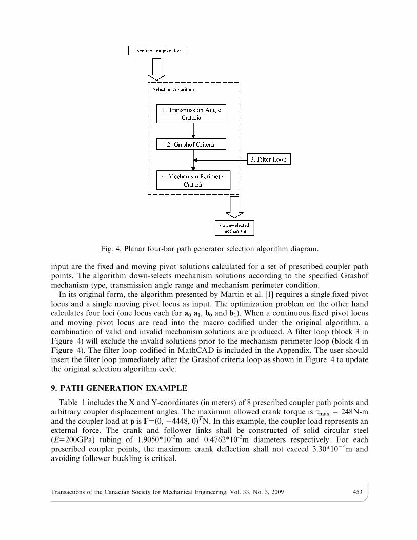
input are the fixed and moving pivot solutions calculated for a set of prescribed coupler pathpoints. The algorithm down-selects mechanism solutions according to the specified Grashofmechanism type, transmission angle range and mechanism perimeter condition.
In its original form, the algorithm presented by Martin et al. [1] requires a single fixed pivotlocus and a single moving pivot locus as input. The optimization problem on the other handcalculates four loci (one locus each for a0 a1, b0 and b1). When a continuous fixed pivot locusand moving pivot locus are read into the macro codified under the original algorithm, acombination of valid and invalid mechanism solutions are produced. A filter loop (block 3 inFigure 4) will exclude the invalid solutions prior to the mechanism perimeter loop (block 4 inFigure 4). The filter loop codified in MathCAD is included in the Appendix. The user shouldinsert the filter loop immediately after the Grashof criteria loop as shown in Figure 4 to updatethe original selection algorithm code.
9. PATH GENERATION EXAMPLE
Table 1 includes the X and Y-coordinates (in meters) of 8 prescribed coupler path points andarbitrary coupler displacement angles. The maximum allowed crank torque is tmax 5 248N-mand the coupler load at p is F5(0, 24448, 0)TN. In this example, the coupler load represents anexternal force. The crank and follower links shall be constructed of solid circular steel(E5200GPa) tubing of 1.9050*10-2m and 0.4762*10-2m diameters respectively. For eachprescribed coupler points, the maximum crank deflection shall not exceed 3.30*1024m andavoiding follower buckling is critical.
Fig. 4. Planar four-bar path generator selection algorithm diagram.
Transactions of the Canadian Society for Mechanical Engineering, Vol. 33, No. 3, 2009 453

Figure 5 illustrates the fixed and moving pivot loci calculated using the nonlinearoptimization problem with a prescribed range of b0x 520.0508, 20.0495…0.0508m and initialguesses (in meters) of b0y 50, b15(0.0381, 0.0635), a05(0.1651, 0.0127) and a15(0.1905,0.1016). The fixed and moving pivot loci are used as input for the updated selection algorithmwith a transmission angle range of 40u#trans.#140u, the Grashof crank-rocker condition and aminimum mechanism perimeter condition. The resulting dimensions (in meters) for the pathgenerator selected (Figure 5 and 7) are b05(0.038100, 20.021057), b15(0.016739, 0.074854),a05(0.147879, 0.090703) and, a15(0.183490, 0.128194). This mechanism has crank, coupler,follower and ground lengths of 0.051707, 0.175074, 0.098260 and 0.156657 meters respectively(satisfying Grashof crank-rocker conditions) and produces the transmission profile illustratedin Figure 6. Figure 7 also includes the coupler path points achieved by the synthesized pathgenerator. This mechanism is the most compact of the available solutions (satisfying minimum
Fig. 5. Path generator fixed and moving pivot loci (with mechanism selection superimposed).
Table 1. Prescribed and achieved coupler path points.
pprescribed [m] aprescribed [deg] pachieved [m] aachieved [deg]
Pos 1 0.129357, 0.129967 0 0.129418, 0.129936 0Pos 2 0.113873, 0.134630 21.5125 0.113995, 0.135758 4.5991Pos 3 0.096378, 0.135545 22.431 0.095829, 0.136428 8.0984Pos 4 0.078395, 0.132283 22.9232 0.078303, 0.131582 10.6369Pos 5 0.027371, 0.091013 20.8910 0.043373, 0.088026 12.2871Pos 6 0.015819, 0.064618 5.7509 0.043861, 0.071780 6.9920Pos 7 0.037338, 0.047701 47.6085 0.049500, 0.061417 5.3094Pos 8 0.073061, 0.073731 46.8257 0.074341, 0.056815 212.1069
Transactions of the Canadian Society for Mechanical Engineering, Vol. 33, No. 3, 2009 454

perimeter condition). Table 2 includes the resulting static torque and deflection of the cranklink as well as the resulting follower link columnar loads. The follower buckling load is 6512N.As noted in Section 5, the link stiffness required to limit transverse deflection for link a0a1
��! isgenerally sufficient in avoiding buckling. The calculated buckling load for link a0a1
��! is over4MN-far exceeding the applied coupler load.
Because the crank and follower links are elastic, the deflections of these links compromise theaccuracy of the coupler path points achieved by the synthesized mechanism. Table 1 includesthe coupler path points and orientation angles calculated from the mechanism deflection modelin Section 3. Because coupler point accuracy is the focus in path generation, the accuracy of theorientation angles approximated by the synthesized mechanism is not critical. Figure 8 is a plotof the scalar differences between the prescribed and achieved coupler path pointsð pprescribed -pachieved
�� ��Þ. Coupler path points 1 through 8 correspond to crank angles of h15
Fig. 7. Coupler path points achieved by synthesized path generator.
Fig. 6. Path generator transmission angles.
Transactions of the Canadian Society for Mechanical Engineering, Vol. 33, No. 3, 2009 455

133.5271u, 112.8409u, 92.5959u, 72.2693u, 8.6884u, 336.4193u, 331.0413u and 294.6046urespectively.
As a comparison between the structural integrity of a path generator calculated using thenonlinear optimization problem and a path generator calculated using Equation (1) and (2)alone, a solution was calculated using the latter model. A prescribed value of a0x 50, the firstfour coupler precision points in Table 1 and initial guesses of a0y 50, a15(0.0381, 0.0635),b05(0.1651, 0.0127) and b15(0.1905, 0.1016) resulted in a0y 5 0.020574, a15( 0.035052,0.079756), b05( 0.367792, 0.011938) and b15( 0.365252, 0.164846). Because the conventionalmodel includes no constraints for buckling and deflection, the calculated four-bar mechanismsolution has a follower scalar length of 0.152908m which is substantially longer than thefollower from the optimization problem solution and much more susceptible to buckling(2131N vs. 6512N in the optimization problem). In addition, the conventional model does notensure full link rotatibility or feasible transmission angles. Although it is possible to calculate akinematically and structurally sound mechanism solution from the convention method by trialand error, the nonlinear optimization problem produces solutions that are kinematically andstructurally sound specifically.
Fig. 8. Scalar differences between prescribed and achieved coupler path points.
Table 2. Crank static torques, deflections and follower columnar loads.
Crank Static Torque[N-m]
Crank Deflection[10-4m]
Follower Load[N]
Pos 1 99.20 0.69 1378.94Pos 2 42.26 0.28 1378.94Pos 3 27.23 0.18 1370.05Pos 4 95.25 0.66 1378.94Pos 5 210.49 1.45 1801.52Pos 6 177.27 0.99 2375.34Pos 7 110.50 0.84 2473.20Pos 8 26.89 0.18 2348.66
Transactions of the Canadian Society for Mechanical Engineering, Vol. 33, No. 3, 2009 456

10. DISCUSSION
In the example problem, the authors prescribed 8 coupler path points. Because the nonlinearoptimization problem formulated in this work can theoretically accommodate an indefinitenumber of precision points, the user is not limited to 8 points. Equation (17) becomes invalidwhen the pivots a1, b1 and b0 are collinear because when collinear, the denominator in Equation(17) becomes zero. Such a state is possible when the four-bar mechanism reaches a ‘‘lock-up’’ orbinding position. The mathematical analysis software MathCAD was used to codify and solvethe formulated nonlinear optimization problem. The cross-sectional area of the follower link, itsslenderness ratio and the column constant determine whether Euler’s or Johnson’s bucklingformula (Equation (19) and (20) respectively) is used. By substituting Euler’s buckling formulawith Johnson’s critical buckling load formula, Equation (22) could be reformulated to considerthe latter buckling condition.
11. CONCLUSION
Although the assumption of link rigidity in kinematic synthesis may be generally appropriateand often practiced, a mechanism under a coupler load will undergo a degree of elasticdeflection-particularly the crank and follower links. Excessive crank deflection and followerbuckling can compromise the accuracy of the precision points approximated and should beconsidered in path generation where coupler loads exist. This work demonstrates the synthesisof a planar four-bar path generator with respect to the following conditions:
N Grashof conditions, transmission angle ranges and mechanism perimeter conditions
N Crank static torque condition
N Crank elastic deflection and follower buckling conditions.
Both the nonlinear optimization problem and modified algorithm ran efficiently in Mathcad-having run times measuring in seconds.
REFERENCES
1. Martin, P.J., Russell, K. and Sodhi, R.S., ‘‘An algorithm for planar four-bar motion generation
with optimization,’’ Transactions of the Canadian Society for Mechanical Engineers, Vol. 31,
No. 3, pp. 357–371, 2007.
2. Yao, J. and Angeles, J., ‘‘Computation of all optimum dyads in the approximate synthesis of
planar linkages for rigid-body guidance,’’ Mechanism and Machine Theory, Vol. 35, No. 8,pp. 1065–1078, 2000.
3. Hong, B. and Erdman, A.G., ‘‘A method for adjustable planar and spherical four-bar linkage
synthesis,’’ ASME Journal of Mechanical Design, Vol. 127, No. 3, pp. 456–463, 2005.
4. Zhou, H. and Cheung, E.H.M., ‘‘Adjustable four-bar linkages for multi-phase motion
generation,’’ Mechanism and Machine Theory, Vol. 39, No. 3, pp. 261–279, 2004.
5. Al-Widyan, K., Angeles, J. and Jesus Cervantes-Sanchez, J., ‘‘The robust synthesis of planar
four-bar linkages for motion generation,’’ Proceedings of the ASME Design Engineering
Technical Conference 5 A, pp. 627–633, 2002.
6. Danieli, G.A., Mundo, D. and Sciarra, V., ‘‘Use of Burmester’s circular theory in the
determination of the optimal four-bar link reproducing actual tibia-femur relative motion,’’
ASME Bioengineering Division, BED 51, pp. 97–98, 2001.
Transactions of the Canadian Society for Mechanical Engineering, Vol. 33, No. 3, 2009 457

7. Goehler, C.M., Stanisic, M.M. and Perez, V.P., ‘‘A generalized parameterization of T1 motionand its applications to the synthesis of planar mechanisms,’’ Mechanism and Machine Theory,Vol. 39, No. 11, pp. 1223–1241, 2004.
8. Caracciolo, R. and Trevisani, A., ‘‘Simultaneous rigid-body motion and vibration control of aflexible four-bar linkage,’’ Mechanism and Machine Theory, Vol. 36, No. 2, pp. 221–243, 2001.
9. Zhixing, W., Hongying, Y., Dewei, T. and Jiansheng, L., ‘‘Study on rigid-body guidancesynthesis of planar linkage,’’ Mechanism and Machine Theory, Vol. 37, No. 7, pp. 673–684, 2002.
10. Lin, S. and Modler, K.H., ‘‘Path generation with emphasis on desired mechanism type andcharacteristics,’’ Proc. of the 11th World Congress in Mechanism and Machine Science, ChinaMachine Press, Tianjin, China, Vol. 3, pp. 1264–169, 2004.
11. Huang, C. and Roth, B., ‘‘Dimensional synthesis of closed-Loop linkages to match force andposition specifications,’’ Journal of Mechanical Design, Vol. 115, pp. 194–198, 1993.
12. Dado, M.H.F., ‘‘Limit position synthesis and analysis of compliant 4-bar mechanism withspecified energy levels using parametric pseudo-rigid-body model,’’ Mechanism and MachineTheory, Vol. 40, No. 1, pp. 977–992, 2005.
13. Venanzi, S., Giesen, P. and Parenti-Castelli, V., ‘‘A novel technique for position analysis ofplanar complaint mechanisms,’’ Mechanism and Machine Theory, Vol. 40, No. 11, pp. 1224–1239, 2005.
14. Sonmez, U., ‘‘Introduction to compliant long dwell mechanism designs using buckling beamsand arcs,’’ Journal of Mechanical Design, Vol. 129, No. 8, pp. 831–843, 2007.
15. Plaut, R.H., Alloway, L.A. and Virgin, L.N., ‘‘A nonlinear oscillations of a buckled mechanismused as a vibration isolator,’’ Proceedings of the IUTAM Symposium, Vol. 122, pp. 241–250, 2003.
16. Sriram, B.R. and Mruthyunjaya, T.S., ‘‘Synthesis of path generating flexible-link mechanisms,’’Computer and Structures, Vol. 56, No. 4, pp. 657–666, 1995.
17. Suh, C.H. and Radcliffe, C.W., Kinematics and Mechanism Design, John Wiley and Sons Inc.,New York, 1978.
18. Pilkey, W.D., Formulas for Stress, Strain and Structural Matrices, John Wiley and Sons Inc.,New York, 1994.
19. Moaveni, S., Finite Element Analysis Theory and Application with ANSYS, Prentice-Hall,Englewood Cliffs, 1999.
20. Han, S.P., ‘‘A Globally Convergent Method for Nonlinear Programming,’’ J. OptimizationTheory and Applications, Vol. 22, p. 297, 1977.
21. Powell, M.J.D., ‘‘A Fast Algorithm for Nonlinearly Constrained Optimization Calculations,’’Numerical Analysis, G. A. Watson ed., Lecture Notes in Mathematics, Springer-Verlag, Berlin,Vol. 630, 1978.
APPENDIX
Filter loop (codified in MathCAD) for planar four-bar motion generator selection algorithm
Cell:5 Mrstack(‘ ‘ ‘ ‘)for i 2 1…rows(Cell) 21
M1r(Celli,0 Celli,1 Celli,2 Celli,3)for j 2 0…(end/2) 21
continue if (Celli,0 ? CRANKj)M1r(‘ ‘ ‘ ‘) if Celli,2 ? CRANKj+(end/2)
Mrstack(M, M1)M
Transactions of the Canadian Society for Mechanical Engineering, Vol. 33, No. 3, 2009 458