an experimental setup for visualizations and measurements
TRANSCRIPT
AN EXPERIMENTAL SETUP FOR VISUALIZATIONS ANDMEASUREMENTS ON FREE HYPERSONIC JETS
Marco BELAN*, Mohsen MIRZAEI*, Sergio DE PONTE**, Daniela TORDELLA***
Abstract: The free hypersonic jets can be found in several technological applicationsand even in astrophysical observations. This article is mainly devoted to explain anexperiment about visualizations and measurements on free hypersonic jets extend-ing on length scales in the order of hundreds of initial diameters and traveling in amedium not necessarily made of the same gas of the jets. The experiments areperformed by means of special facilities where the jet Mach numbers and the jet-to-ambient density ratios can be set independently of each other, what permits theinvestigation of a wide parameters range in the relevant physics. The Mach numberof the jets ranges from 5 to 20 and the jet-to ambient density ratio, which plays animportant role in the jets morphology, can be set from 0.1 up to values exceeding100. The present setup produces the jets by means of a fast piston system (forhigh Mach numbers) or injection valves (for low Mach numbers), both coupled withde Laval nozzles. The visualizations and measurements are based on the electronbeam technique: the jets are weakly ionized, then a fast CMOS camera capturesimages that are analyzed by image processing techniques. A sample of the resultsobtained by this experimental system is included at the end of this work.
1 INTRODUCTIONThe term "free hypersonic jet flow" is the name given to the fluid dynamics phenomenon producedby a jet exhausting at hypersonic velocity in a surrounding unbounded stationary medium. In the lastdecades, hypersonic jets have received much interest from researchers because of their importanceboth in basic fluid dynamics and in applications for aeronautical and mechanical industries. Theseextremely collimated flows can also be observed in natural phenomena such as the young stellar objects(YSO). The literature about these topics is huge in numerical simulations and experiments, even just thefundamental works are too numerous to be cited here. Nevertheless, aero-and astronautical applicationsare mainly focused on the jet near field, on jet control and jet-body interactions. In the astrophysics fieldthe scenario is different, because many observational data and numerical simulations deal with longscale jets; however, also in astrophysics the experimental results deal in general with short jets, aspulsed, short convergent flows of plasma or jets created by laser ablation of shaped targets [1, 2, 3]. Ingeneral it’s hard to find experimental works about the long scale behavior of hypersonic jets evolving inan external medium that may consist also in a gas different from the one of the jet.The present experiment was conceived in such a way as to include the study of natural phenomena, i.e.the stellar jets known in astrophysics, which can have lengths in the order of hundreds, even thousands,initial diameters. In these jets, several physical parameters, expressed as non-dimensional similaritynumbers, affect the physical behaviour; in the long term evolution, Mach number, jet-to-ambient densityratio, Reynolds number and heat flow numbers are in general important. In particular, in a stellar jetReynolds number and temperatures can reach huge values, impossible to scale in a laboratory, whilstthe other crucial parameters, namely the Mach number and the jet-to-ambient density ratio, can bematched in a real experiment, like the one presented in this work. A long-standing issue about stellarjets was also the possible effect of magnetic fields on the jets morphology, but this problem is not
* Marco Belan, Dipartimento di Ingegneria Aerospaziale, Politecnico di Milano, Italy, [email protected]* Mohsen Mirzaei, Dipartimento di Ingegneria Aerospaziale, Politecnico di Milano, Italy, [email protected]** Sergio de Ponte, retired, formerly Dipartimento di Ingegneria Aerospaziale, Politecnico di Milano, Italy, [email protected]*** Daniela Tordella, Dipartimento di Ingegneria Aeronautica e Spaziale, Politecnico di Torino, Italy, [email protected]
EPJ Web of Conferences 25, 01056 (2012) DOI: 10.1051/epjconf/20122501056 © Owned by the authors, published by EDP Sciences, 2012
This is an Open Access article distributed under the terms of the Creative Commons Attribution License 2.0, which permits unrestricted use, distribution, and reproduction in any medium, provided the original work is properly cited.
Article available at http://www.epj-conferences.org or http://dx.doi.org/10.1051/epjconf/20122501056

considered in the present study because our experiment has been designed to investigate the universalphenomenology in newtonian dynamics, regardless of the presence of electromagnetic forces.In this article we describe an experiment which is about visualizations and measurements on hypersonicjets extending on length scales in the order of hundreds of initial diameters and traveling in a medium notnecessarily made of the same gas of the jets. By our experiment, the Mach number M and the jet-to-ambient density ratio η = ρj/ρa can be set independently each other to find the effect of each parameteron the jet behaviour. The Mach number of the jets ranges from 5 to 20; the density ratio η, which playsan important role in the jets morphology, can be set from 0.1 up to values exceeding 100. These twoparameters are in similitude with astrophysics parameters in the hydrodynamic limit. As a consequenceof the setup, the Reynolds number cannot be set independently; it ranges from 104 to 5 · 105. The planof the paper is the following: in Section 2 we present the apparatus setup, Section 3 is about calibrationmethods and measurement techniques, Section 4 is dedicated to some experimental results, and theconclusions are drawn in Section 5.
2 EXPERIMENTAL SETUPThe facilities presented here are designed and built specifically for the generation and display of hy-personic jets. The first version of this system was already employed to study the properties of highlyunderexpanded jets, making use of truncated nozzles and color CCD cameras, detailed information canbe found in the works by Belan et al. [4, 5, 6, 7]. In present work the system was reconfigured, byadding and improving devices for the present purpose, i.e. long scale jets, pressure matched or nearlymatched.
2.1 NOZZLESThe jets under study are generated by de Laval nozzles, specially designed for monoatomic gases flows.The gas acceleration inside an ideal nozzle of this kind working under matched conditions follows theknown formula of one-dimensional isentropic flow:
p0
pj=
(1 +
γ − 12
M2
) γγ−1
(1)
where p0 is the stagnation pressure and pj is the pressure of the gas at the nozzle exit. The set ofnozzles used in this experiment (figure 1) was designed taking into account the real gas properties,so that the ideal pressure ratios were corrected by numerical calculations of boundary layer and heatexchange. The resulting pressure ratios are slightly different from the corresponding ideal ratios, andare reported in table 1. All the nozzles have the same converging section and throat (diameter=2mm),whilst the diverging section depends on the design Mach number, the relevant output diameters are alsoreported in table 1.
Mach Number p0/pj output diameter [mm]
5 270.3 6.3
10 6.667× 10³ 24.0
15 4.762× 10⁴ 71.4
20 1.786× 10⁵ 121.9
Table 1: Pressure ratios at matched conditions for different Mach numbers
Obviously, the generation of a high Mach number jet in an ambient at atmospheric pressure wouldrequire too high stagnation pressures. Therefore, to obtain the pressure ratios indicated in table 1,especially for higher Mach numbers, it is necessary to combine a decrease in ambient pressure andan increase in stagnation pressure, so that the best solution is to use a vacuum chamber together witha driving system able to compress and heat the gas to the required level. The pressure level in theenvironment at the nozzles output is obtained by means of a vacuum vessel, purposely designed. The
EPJ Web of Conferences
01056-p.2

Mach 5
Mach 10
Mach 15
Mach 20
0.1m
Figure 1: The set of nozzles used in this experiment (longitudinal sections)
stagnation pressures are obtained by means of a piston system at the higher Mach numbers and aninjector at the lower Mach numbers.
2.2 VACUUM VESSELThe jets under study are created inside a modular vacuum vessel, with a maximum length of 5m and adiameter of 0.5m. The vacuum is obtained through two vacuum pumps, a lobe pump and a vane pumpin cascade configuration, these two devices are capable to lower the internal pressure down to 0.5 – 1Pa. All parts in the vessel are designed according to the correct principles of vacuum technology [8].The vessel diameter is much larger than the jets diameter, so the lateral walls effects are negligible andthe jets can be considered as free jets until they hit the vessel’s end. The required ambient pressureinside the vessel is obtained by means of a valves system which sets the desired ambient density (atpressures in the range 1.5 to 100 Pa) using a gas in general different from the jet gas. Pressures insidethe vessel are monitored by means of two 0.25% accuracy transducers, ranging from 0.01 to 10 Pa andfrom 0.1 to 100 Pa. The full version of the vessel (figure 2) is composed of three cylindrical sections(2,3,4) plus a head and a tail section (1 and 5). The head segment has a port for the connection ofan electron gun, an optical window for a camera and service ports for vacuum pump, ambient gas inletand electrical connections. Also one of the intermediate sections is provided with similar ports. Themodularity of the apparatus involves the considerable advantage of fitting the total volume and lengthdepending on the needs of the individual tests: a larger size is needed to monitor the development ofhigh Mach number jets, because of their larger diameter, in such a way as to follow the jet evolution overa large number of diameters. The sample results presented in this work are obtained by means of a3-sections setup made of sections 1,2 and 5, where the useful internal vessel length is 2.46 m.
2.3 FAST PISTON SYSTEMEach de Laval nozzle operates at a single nominal Mach number (slight adjustments are possible), whichis obtained by imposing a given pressure ratio between the compressed gas to the ambient pressure.At the higher Mach numbers considered here (M ≥ 10), the apparatus which feeds the nozzles mustbe able to increase significantly the enthalpy of the gas, while reaching the desired stagnation pressureand temperature. For this purpose, we use a purely mechanical system, a fast piston system purposelydesigned, which compresses the jet gas to stagnation pressure in the 0.1 to 0.7 MPa range. It has anannular shape and it slides between two coaxial cylinders, as shown in figure 3. The piston is providedwith a forward cylindrical extension having a set of ports. The inner cylinder is connected to the nozzleinlet by a second set of ports. The two port sets form a valve system which is closed during the pistonrun, and open when the compressed gas reaches the desired stagnation conditions. When the piston
EFM11
01056-p.3

piston/nozzlesfitting
aux ports head ports
primary pumps fitting
camerawindow
nozzle
electron gun head
jet axis
section 5 section 4 section 3 section 2 section 1
Figure 2: Vacuum vessel and experiment setup drawn in full configuration. Top panel: top view. Bottompanel: longitudinal section. The camera window, depending on optical port size and lens in use, is theactual test region.
reaches this position, the two sets of ports match each other and the compressed gas flows into thenozzle. The piston is moved by compressed air, it is normally held by an electromagnet and the startingtime can be programmed on an electronic timer. The proper use of the piston requires well definedprocedures for timing and loading of the jet gas, they are described in the following section. Loadpressures are measured by means of 1% accuracy transducers. A separate transducer is available tocheck stagnation pressures: when needed it can be assembled in place of the nozzle. The resultingrepeatability of the jets at each piston run is very good. Of course, the valves require a finite time topass from the closed to the open condition; therefore the jet mass flow Q has an increasing and adecreasing phase. At the end of compression run, owing to the valves opening, the outflow increasesto a maximum value, which is in the order of the mass flow of the same nozzle under steady conditions,then it diminishes as the residual gas contained in the piston is used up. Figure 4 shows a typical gasinjection curve.
jet gas inlet
piston ports
nozzle
inner cylinder ports
annularpiston
Figure 3: Longitudinal section of the fast piston system, here connected to the Mach 10 Nozzle
EPJ Web of Conferences
01056-p.4

0.00 0.02 0.04 0.06 0.080
1
2
3
4
5
6
7
Time [s]
Q [kg/s x10-5]
Figure 4: Jet gas injection: an example of mass flow vs time for an Helium jet at Mach 10
2.4 JET GAS INJECTORAt the lowest Mach number considered here, the pressure ratio is so low that the piston system cannotafford it, because of leakages and frictional effects. The nominal pressure ratio for Mach 5 is about 270:this means that, for example, a typical ambient pressure in the vessel of 10 Pa, equal to the jet pressurepj under matched conditions, would require a stagnation pressure p0 of 2700 Pa, too low to reach after acompression run. To reach values of p0 in this range we replace the piston with a direct injection systemwhich drives the required low pressure gas into the relevant nozzle. This device receives the jet gas bya set of fast solenoid valves, controlled by an electronic timer. The input pressure is set by extra devices,described in the procedures section. Figure 5 shows a simple sketch of the system, which is usable alsowith the Mach 10 nozzle.
Vessel wall
Mach 5 nozzle
Solenoid valves
fromReservoir
Timerline T2
Figure 5: Longitudinal section of the injection system for Mach 5
2.5 VISUALIZATIONS AND MEASUREMENT DEVICESThe visualizations and measurements are based on the electron beam method. To this purpose, anelectron gun was specifically designed and built in the laboratory, thanks to the design notes availablein literature [9]. This electron gun creates an adjustable beam, up to 2 mA at 20 kV, and it is equippedwith a deflection system to create an electron sheet. This device operates at very low pressures thanks
EFM11
01056-p.5
to two turbomolecular pumps. The electron sheet intercepts the jet under test, so that the absorptionof light by a population of gas molecules raises their energy level to a brief excited state. As theydecay from this excited state, they emit fluorescent light [10]. This fluorescent light generates a planefluorescent section of the flow and images of the fluorescent zone can be acquired by different kindsof cameras, including intensifiers, depending on the experiment to be performed. The sample resultsshown in the last section are acquired by a fast CMOS camera (Phantom V5.1) which captures 512x512or 768x768 monochromatic images at frame rates of 2000 to 5000fps. The camera and the electrongun can be mounted on several ports and optical windows, in the present setup they are mounted onthe head section (see figure 2). Besides visualizations, gas densities and structure velocities can bemeasured by image processing. In particular, the values of the gas density along an image can beobtained by the well known relation between light intensity and gas density [11, 12], taking accountcarefully of the gas species involved in the measurement. Measurements of velocities can be obtainedby standard correlation techniques [13], applied to the typical macroscopic structures appearing in thejet morphology, such as the head bow shock, secondary moving shocks or expansions and mixing layersinstabilities.
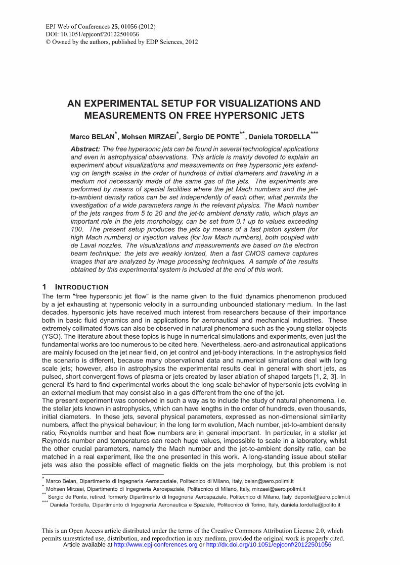
3 CALIBRATION AND MEASUREMENT TECHNIQUESIn each run at a given Mach number, a pair of gases is selected for jet and ambient. The availablegases are helium, argon, xenon and air, only the first three ones are used for the jet since the nozzlesare designed for monoatomic gases. The required ambient inside the vessel is obtained by means of avalve injection system which sets the desired ambient density (at pressure in the 1.5 to 20 Pa range) byusing a gas in general different from the jet gas.
Cylinder -Piston System Vacuum Vessel
Jet Gas Bottle
AmbientGas Bottle
VacuumPump
Control System
Δt2 Δt1
Pa
Patp
air vent Valve
Figure 6: General diagram of the system controls and connections
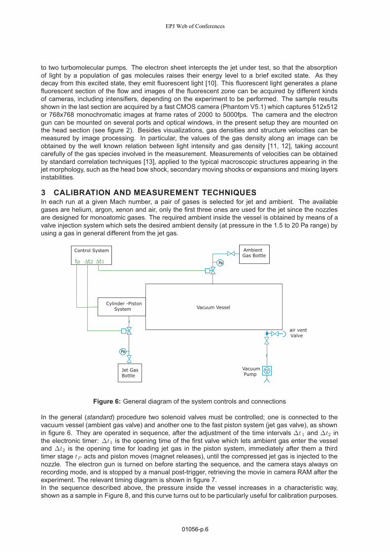
In the general (standard) procedure two solenoid valves must be controlled; one is connected to thevacuum vessel (ambient gas valve) and another one to the fast piston system (jet gas valve), as shownin figure 6. They are operated in sequence, after the adjustment of the time intervals Δt1 and Δt2 inthe electronic timer: Δt1 is the opening time of the first valve which lets ambient gas enter the vesseland Δt2 is the opening time for loading jet gas in the piston system, immediately after them a thirdtimer stage tP acts and piston moves (magnet releases), until the compressed jet gas is injected to thenozzle. The electron gun is turned on before starting the sequence, and the camera stays always onrecording mode, and is stopped by a manual post-trigger, retrieving the movie in camera RAM after theexperiment. The relevant timing diagram is shown in figure 7.In the sequence described above, the pressure inside the vessel increases in a characteristic way,shown as a sample in Figure 8, and this curve turns out to be particularly useful for calibration purposes.
EPJ Web of Conferences
01056-p.6
EnteringAmbient Gas
LoadingJet Gas
ReleasingMagnet
tp
TCamera
Δt1 Δt2
Figure 7: Time diagram of valve system, fast piston system and camera
Obviously, the curve doesn’t start from zero, since the vessel is not ideal, and there is always residualair due to unavoidable small leakages. When the first timer stage acts, the first solenoid valve is openedfor an interval Δt1 and during this time ambient gas enters the vessel, so the pressure goes up from p1
(residual air) to p2 = pa, then during the jet gas loading phase in the cylinder (Δt2), ambient gas reachesa steady state∗, and just afterΔt2, the magnet releases the piston and, after a fast compression lastinga measurable time, the jet gas escapes through the nozzle. The jet travels through the vacuum vesselin the subsequent time interval Δtj, also called jet lifetime. It can be shown that the duration of the jetsin this experiment is well longer than their physical time scale, defined as the sound crossing time on ajet radius [13], so the jets may be considered nearly steady. However, on the time scale of the operatingprocedure their lifetime appears always much shorter than the gas loading times Δt1 and Δt2. Δtj canbe estimated directly by the pressure curve as in figure 8, but the final value is safely measured fromthe movie, since the camera has a very good temporal resolution, working at frame rates in the order ofthousands per second. The jet flow leads rapidly the pressure to the maximum value p3 and finally, atthe end of the experiment, the pressure begin to decrease again because of vacuum pumps.By pressure diagram, a complete calibration of the system can be stated. About the ambient pressure,it is almost immediate to find calibration charts in the form
pa = F (pas, Δt1) (2)
where pas (ambient supply pressure) is the pressure fed by the ambient gas bottle. About the jet, thecalibration of timeΔt2 and piston supply pressure ps, in order to obtain a matched jet having the desiredproperties, is much more complicated as shown in what follows. In the throat of a de Laval nozzle, gasflow is choked, so the equation for the jet mass flow rate can be written in the ideal case by means ofstandard gas dynamics relations:
m = Acρ0c0
(2
γ + 1
) 12
γ+1γ−1
(3)
where Ac is cross-sectional area of the throat whilst ρ0 and c0 are stagnation density and speed ofsound. This formula can be rewritten in terms of stagnation pressure and temperature by means of theideal gas law p = ρRjT :
m = Acp0
(γ
RjT0
) 12
(2
γ + 1
) 12
γ+1γ−1
. (4)
∗About the ambient pressure, it is worth to mention that it must be set taking account of the best working conditions for theelectron gun, approximately below 20 Pa, because for higher pressures the resulting image quality may decrease remarkably.
EFM11
01056-p.7

0.5 1.0 1.5 2.0 2.5 Time [s]
0
5
10
15
20
Pressure [Pa]
Δtjp1
p3
p2
Δt2Δt1
Figure 8: Pressure diagram inside the vacuum vessel during a sample run
At the end of the experiment, the jet gas is completely mixed with the ambient gas and it can be assumedthat the mixture has the room temperature Ta, because the mass of the ambient gas is much greaterthan the one of the jet and because of the fast effect of heat radiation from the vessel walls. Thus thepressure increase due to the jet Δp = p3 − p2 shown in fig. 8 can be related to the density increase Δρinside the vessel volume V and to the jet mass flow:
Δp
RjTa= Δρ =
m
V=
∫Δtj
m
Vdt (5)
Now by replacing (4) in (5) and rearrange the formula it is found:
Δp =AcTa
V
∫Δtj
p0
(Rjγ
T0
) 12
(2
γ + 1
) 12
γ+1γ−1
dt (6)
Here the crucial parameters p0 and T0 are not independent since they are due to the compression inthe piston. For a fast ideal isentropic compression they can be related to the supply pressure ps andtemperature Ts = Ta, i.e. p and T of the gas loaded from the bottle into the piston,
T0 = Ts
(p0
ps
) γ−1γ
. (7)
The combination of (5) and (6) leads to:
Δp =AcTa
V
∫Δtj
p0
(ps
p0
) γ−12γ
(Rjγ
Ta
) 12
(2
γ + 1
) 12
γ+1γ−1
dt (8)
This formula shows how the final increase in vessel pressure Δp and the jet lifetime Δtj are related tothe pressure ps of gas initially loaded into the piston and to the stagnation pressure p0 at the end of thecompression. Δp,Δtj and ps can be measured directly, so the formula can be used to express p0, whichin turn depends on the gas loading time Δt2, and finally leads to calibration charts of the kind
p0 = G(ps, Δt2) (9)
EPJ Web of Conferences
01056-p.8

whereΔtj doesn’t appear because it is not an independent parameter, actually the jet lifetime for a givennozzle properly working depends on the quantity of gas available, which is automatically set by selectingps, Δt2. Up to now, the derivation of the calibration charts was based on ideal conditions, as a furtherstep accurate calibration charts must then be obtained including corrections for non ideal effects likesmall heat losses, dependence on the piston driving pressure, frictional effects and progressive openingof the piston valves, so that they take the form
p0 = G(ps, Δt2, pp, k) (10)
where pp is the piston driving pressure and k is a set of coefficients related to the laboratory conditions.Finally, the values of p0 and T0 yield pressure, temperature and density at nozzle exit, so that thecalibration charts can be used to set the desired properties.For example, first step to get an hypersonic jet is to find a good pressure ratio for a given de Lavalnozzle (table 1). Then, after having set piston driving pressure and supply pressures, changing Δt1
and Δt2 gives different pressures for ambient and jet respectively. Typically, for a given nozzle, a set ofexperiments is performed changing the parametersΔt1, Δt2 whilst pas, ps and pp are kept constants, ingeneral they are set afresh when a new nozzle is assembled on the system. Furthermore, in a set ofexperiments Δt2 can be adjusted to obtain well matched jets or even slightly unmatched jets, having ajet-to-ambient pressure ratio pj/pa in an approximated range 0.7 to 1.3, since the boundary layer insidethe nozzles has stabilizing effects against the pressure unmatching [14]; this gives rise to interesting flowmorphologies, appearing as perturbations of a properly matched jet (for slightly unmatched jets it is alsopossible to calculate corrections to the nominal Mach number). Bringing the pressure ratio outside ofthis range leads instead to the formation of strong shocks and expansions close to the nozzle exit, i.e. todefinitely over- or underexpanded jets. In general, these jets are greatly affected by turbulence, so thatthe mixing with the surrounding ambient becomes faster than in matched jets; when this phenomenontakes place, it can be observed in the camera window.The research project is divided in four parts; for each part a nozzle, i.e. a nominal Mach number ischosen, then density ratio is varied by selecting different gases and/or adjusting the pressure ratio.In what follows, first part is Mach 20, second Mach 15, third Mach 10, and fourth is Mach 5. Theexperimental procedure for each part is different from the other ones as explained below.
3.1 MACH 20 PROCEDURESThe de Laval nozzle for Mach 20 has a large diameter, so that it is necessary to put the vessel in a longconfiguration in order to observe jets extending for a sufficient number of initial diameters. Accordingto table 1, matched pressure ratio p0/pj is close to 180000, so for a typical test at ambient pressurepa up to 10 Pa, stagnation pressure should grow up to about 18 bar, what may create safety problemsin our system. The solution is to decrease ambient pressure to the minimum value (about 1.5 Pa), butas mentioned, vacuum vessel is not ideal and at low pressures residual air becomes predominant. Toovercome this problem, vessel is filled by ambient gas up to more than 20 Pa, then a timer let the vacuumpumps work for a given time, in such a way as when vessel pressure reaches again the minimum level,the residual gas can be considered almost pure ambient gas. Timer stage Δt2 must be set in advancein order to obtain the desired jet, and after this point the general procedure described above can befollowed until the experiment is completed.
3.2 MACH 15 PROCEDURESAccording to table 1, the matched pressure ratio p0/pj for Mach 15 is about 48000, well affordable by thesystem in standard configuration. In this case the standard procedure described above can be followedas it stands.
3.3 MACH 10 PROCEDURESFor Mach 10 the calibration and test procedures are more complicated. The main issue is the matchedpressure ratio p0/pj , which in this case is about 6700. One way to obtain this pressure ratio is increaseambient pressure, but there is a limitation, because by increasing the ambient pressure, the quality ofimages worsens. To satisfy the pressure ratio for a typical test at ambient pressure < 10Pa, stagnationpressure should be< 0.7bar, i.e. less than atmospheric pressure. This condition creates problems in theloading phase of the piston, since it becomes necessary to load low pressure gas and then recompress itto the final p0 < 1bar avoiding contamination from the surrounding ambient. To get the proper stagnation
EFM11
01056-p.9

pressures, another system has been designed. As shown in Figure 9, a small reservoir has been addedto the jet gas pipe to keep inside it some amount of gas; its pressure is a bit more that atmosphericpressure. Once this reservoir is full, the valve of jet gas bottle is closed and by adjusting a precisionvalve connected to the vacuum pumps, the pressure of jet gas in the reservoir is reduced to the desirableone (in the order of 0.4 bar). Again, the desired pressure ratio is obtained by presetting Δt1 and Δt2.
Cylinder -Piston System Vacuum Vessel
AmbientGas Bottle
VacuumPump
Pa
Jet Gas Bottle
Reservoir
Pa
Pa
Control System
Δt2 Δt1tp
air vent Valve
High Precision Valve
Figure 9: Sketch of modified system for Mach 10
3.4 MACH 5 PROCEDURESThe test procedures for this part are necessarily different because of the new device used instead ofthe piston. The setup for this case is shown in Figure 10. At first the reservoir is emptied by opening
air vent Valve
InjectionSystem Vacuum Vessel
Jet Gas Bottle
AmbientGas Bottle
VacuumPump
Control System
Δt2 Δt1
Reservoir
Pa
Pa
Pa
High Precision Valves
Figure 10: Sketch of modified system for Mach 5
the valve connected to the vacuum pump, then the test gas enters the reservoir increasing the pressureup to levels in the order of 0.3 bar by means of a high precision valve. When the pressure inside thereservoir satisfies the pressure ratio, the experiment can be started. In this procedure, the timer stage
EPJ Web of Conferences
01056-p.10

Δt1 sets the ambient as before, but the stageΔt2 controls directly the injection, i.e. the gas flows throughthe injector for the time Δt2, then the flow is interrupted. Jet duration is thus directly set by the openingtime of the valves connected to the injector. In this case the third timer stage is not used. At the time ofwriting this report, the first tests of this injector are in progress.
4 RESULTSIn this section, we present some sample results obtained by the present experimental system.Figure 11 shows the head of a xenon jet traveling in an argon ambient, it is a matched jet obtained bysetting a stagnation/ambient pressure ratio p0/pa = 5.17 · 104 ± 10% and an ambient pressure pa =10.5 ± 0.1Pa. These parameters lead to a nearly matched jet having at the nozzle exit a Mach numberM = 15.1 and a density ratio η = 77, thus the jet is highly overdense in comparison with the surroundingambient. The jet structure visible in figure 11 may be interpreted as follows [2]: the jet head is made of abow shock, traveling left to right, clearly visible in figure, followed by a terminal shock much smaller thanthe bow shock, and in this case very close to it, so that it cannot be resolved in the image. On the right ofthe bow-terminal shock structure, only the unperturbed ambient gas is visible; on the left of this structure,the jet core is clearly visible, it is made of xenon traveling at a velocity vg which can be estimated about(560± 20)m/s. This velocity is larger than the one of the shock structure vh = (210± 50) m/s, measuredby correlation techniques, so that the jet gas, after being decelerated by the terminal shock, is deflectedsideways and form a small backward flowing region behind the bow shock, the so-called cocoon, whichthen mixes with the ambient gas. Since the velocity of the head structure is known, two images insuccession can be superimposed after shifting the second one by the displacement of the structureunder study. Then, this procedure can be repeated, so that a reconstruction of a part of the jet structurecan be done by superimposing parts of adjacent frames, obtaining an image larger than what the camerawindow allows. This method is used for all the figures in this section; of course, it has a physical meaningonly if the changes in structure properties are slow in comparison with the interframe time.
Figure 11: Head region of a heavy jet, Xenon in Argon at M = 15.1, density ratio η = 77. The verticalsize of the image is 340mm = 9.5 nozzle radii.
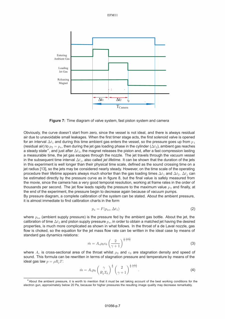
The images presented here come from a movie made of 150 frames taken at 4300 frames per s, anoutline of the movie converted in reconstructed parts of the jet is presented in figure 12. Frame 15 to 30,as in figure 11, show the morphology of this jet as a free flow, i.e. practically not perturbed by the wallseffects. After image 30, the jet head impacts the vessel end, so that a strong backflow is generated andthe flow inside the vessel becomes a jet surrounded by a coaxial stream flowing backward (this is nota naturally backward flow like the cocoon). Under these conditions, the interface between the two flowsbecomes unstable, so that strong waves appear, they move forward at high velocities v i > vh and areparticularly visible in the frames 61 to 90.Figure 13 shows a helium jet traveling in a xenon ambient, it is a slightly unmatched jet obtained bysetting a stagnation/ambient pressure ratio p0/pa = 3.88 · 104 ± 20% and an ambient pressure pa =10.0 ± 0.1Pa. These parameters lead to a jet having at the nozzle exit a Mach number M = 13.4 anda density ratio η = 0.9, thus the jet is slightly underdense in comparison with the surrounding ambient.This jet has a Mach number close to the one of figure 11, but the density ratio is much lower than in thatcase, what changes the jet morphology deeply. Figure 13 is obtained by the superposition techniqueexplained above, and refers to the free jet behaviour, i.e. before the impact with the vessel end. It hasthe same scale of figure 11. Here the shape of the terminal/bow shock structure is remarkably differentfrom the previous case, owing to the heavy xenon ambient which contrasts the light jet advancing.Furthermore, the backward flowing cocoon becomes very large in comparison with the size of the jetcore, which is now surrounded in turn by a region of fast expanded jet gas (dark in the image) and by an
EFM11
01056-p.11
15-30
121-150
91-120
61-90
31-60
Figure 12: Sequence of reconstructed images for the heavy jet Xe in Ar at M = 15.1, η = 77 obtainedas superpositions of scaled correlated frames from the original movie. The numbers on the left refer tothe frame positions in the movie.
unstable interface between jet gas and ambient gas. Here also the velocities are very different from theoverdense jet case, actually the core gas velocity vg can be estimated about (3200± 300)m/s, whilst themeasured value of the head structure is vh = (350 ± 50) m/s, so the ratio vg/vh is much higher in thiscase.
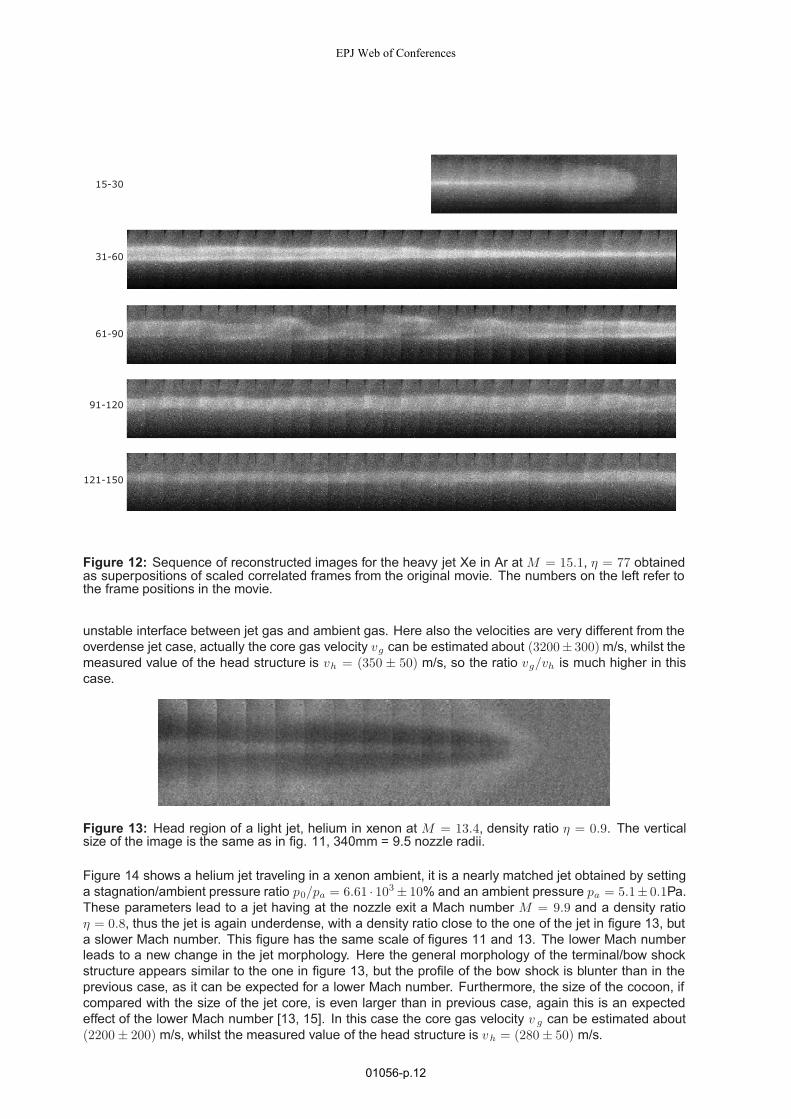
Figure 13: Head region of a light jet, helium in xenon at M = 13.4, density ratio η = 0.9. The verticalsize of the image is the same as in fig. 11, 340mm = 9.5 nozzle radii.
Figure 14 shows a helium jet traveling in a xenon ambient, it is a nearly matched jet obtained by settinga stagnation/ambient pressure ratio p0/pa = 6.61 · 103 ± 10% and an ambient pressure pa = 5.1± 0.1Pa.These parameters lead to a jet having at the nozzle exit a Mach number M = 9.9 and a density ratioη = 0.8, thus the jet is again underdense, with a density ratio close to the one of the jet in figure 13, buta slower Mach number. This figure has the same scale of figures 11 and 13. The lower Mach numberleads to a new change in the jet morphology. Here the general morphology of the terminal/bow shockstructure appears similar to the one in figure 13, but the profile of the bow shock is blunter than in theprevious case, as it can be expected for a lower Mach number. Furthermore, the size of the cocoon, ifcompared with the size of the jet core, is even larger than in previous case, again this is an expectedeffect of the lower Mach number [13, 15]. In this case the core gas velocity v g can be estimated about(2200 ± 200) m/s, whilst the measured value of the head structure is vh = (280 ± 50) m/s.
EPJ Web of Conferences
01056-p.12

Figure 14: Head region of a light jet, helium in xenon atM = 9.9, density ratio η = 0.8. The vertical sizeof the image is the same as in fig. 13, 340mm = 28.3 nozzle radii in this case.
5 CONCLUSIONSThe whole facility is reliable in the different configurations and usable in a wide range of Mach Numbers.The use of matched or quasi-matched de Laval nozzles allows to have rather well known boundaryconditions of the jets. The calibration procedures developed for the different Mach Numbers are alsoreliable, so that the set of experiments may be further carried on following the ones yet conducted,where the whole set of experimental conditions is well and clearly defined. Thanks to the geometry ofthe devices for the jet generation, even the repeatability of each experiment is very good.The distance of observation, as referred to the initial jet diameter, is far larger than any of the availableexperiment and is in the range of stellar jets, while it is not the only purpose of these facilities, as showne.g. in [6]. Although real stellar jets are not generated in this way, the development of the jets and ofthe observed instabilities in form of ”knots” are not related to boundary conditions but are part of the jetdevelopment itself. Both overdense and underdense jets may be simulated in a wide range of densityratios and this has allowed to have an insight in the change both in jet and cocoon structures, and also inthe instabilities that appear on streams interfaces. The fact that the jet structure is persistent even afterthe impact on the vessel end, although is not part of the stellar jets effort of simulations, is interesting asit is a new piece of knowledge.About the results, it has been shown that many of the facets of stellar jets may be simulated in a purefluid dynamic experiment, without the need of electromagnetic fields, what is an important issued inastrophysics [13]. Although the quality of the images is not so good as desirable, due to the cameralimits, they may be elaborated to get enough data, while the use of a camera with higher performancesis the most urgent further development of the experimental setup.
REFERENCES[1] Ferrari A.: Modeling extragalactic jets, Annual Rev. Astron. & Astrophys. 36 539, 1998
[2] Gouveia Dal Pino E.M.: Astrophysical jets and outflows, Advances in Space Research 35 908–924,2005
[3] Bellan P.M., Livio M., Kato Y., Lebedev S.V., Ray T.P., Ferrari A., Hartigan P., Frank A., Foster J.M.,Nicolaï P.: Astrophysical jets: Observations, numerical simulations, and laboratory experiments,Phys. Plasmas 16 4, 2009
[4] Belan M., Tordella D., De Ponte S.: A system of fast acceleration of a mass of gas for the laboratorysimulation of stellar jets, 19th ICIASF, Cleveland, August 27-30, 2001
[5] Belan M., De Ponte S., Massaglia S., Tordella D.: Experiments and numerical simulations on themid-term evolution of hypersonic jets, Astrophys Space Sci 293 (1-2): 225-232, 2004
[6] Belan M., De Ponte S., Tordella D.: Determination of density and concentration from fluorescentimages of a gas flow, Exp. Fluids 45 501511, 2008
[7] Belan M., De Ponte S., Tordella D.: Highly underexpanded jets in the presence of a density jumpbetween an ambient gas and a jet, Physical Review E 82 026303, 2010
[8] Roth A.: Vacuum Technology, North-Holland Elsevier, 1990
EFM11
01056-p.13

[9] Bakish R., Wiley J. & Sons: Introduction to Electron Beam Technology, NY, 1962
[10] Brown L.O., Miller N.: α-Ray induced luminescence of gases, Trans. Faraday Soc. 53: 748, 1957
[11] Muntz E.P.: The electron beam fluorescence technique, AGARDograph 132, 1968
[12] Bütefisch K.A, Vennemann D.: The electron-beam technique in hypersonic rarefied gas dynamics,Prog Aer Sci 15: 217-255, 1974
[13] Tordella D., Belan M., Massaglia S., De Ponte S., Mignone A., Bodenschatz E, Ferrari A.: Astro-physical jets: insight into long term hydrodynamics, New J of Physics 13, 043011, 2011
[14] Huzel D.K., Huang D.H: Design of liquid propellant rocket engines, NASA report SP-125, 1967
[15] Massaglia S., Bodo G., Ferrari A.: Dynamical and radiative properties of astrophysical supersonicjets I. Cocoon morphologies, Astron & Astrophys 307 997, 1996
EPJ Web of Conferences
01056-p.14