rf ingress measurements for shielded twisted pair · pdf filerf ingress measurements for...
TRANSCRIPT
RF Ingress Measurements for Shielded Twisted Pair (STP)
Cables from Automotive BCI Test
Larry Cohen
Ramin Shirani
1
2
Overview• Main Purpose: Measurement of the induced MDI port voltage from a standard automotive
radiated immunity bulk current injection (BCI) test with samples of shielded twisted pair (STP) automotive harness cable
–The BCI test method is described in ISO 11452-4; this procedure is generally used only up to 400 MHz for testing RF immunity of automotive cable harnesses
–Two different 2 meter cable samples: Single pair STP with H-MTD connectors, shielded star-quad with HSD connectors (only one pair active); both samples 2 meters long with only end connectors
–Power cables not subjected to BCI; test setup intended to measure BCI ingress only on signal port
• Brief description of shielded star-quad cable
• Procedure and setup diagram for measurement of induced MDI port voltage from BCI test
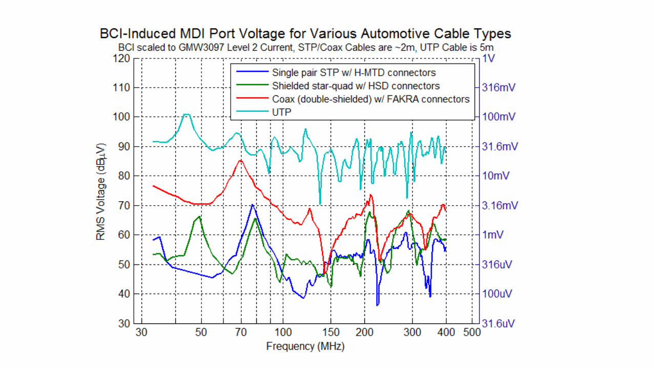
• Measurement plots of MDI port voltage levels vs. frequency
–Comparison of STP cables with coaxial cable and UTP cable
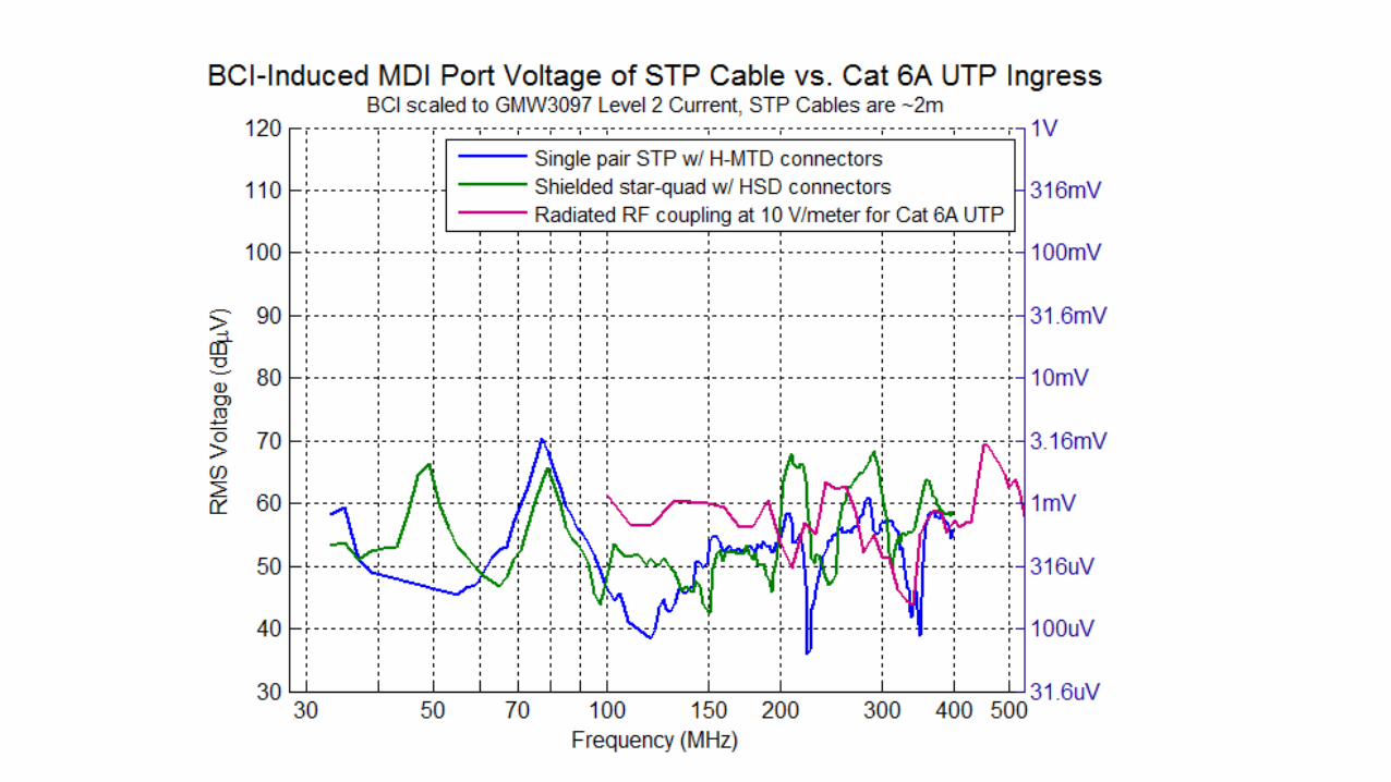
–Comparison of STP cables and comparison with RF ingress of Cat 6A UTP at 10 V/meter (RF ingress measurement data from study group contribution cohen_3NGAUTO_01_022117)
• Main observation
–The BCI-induced MDI port voltage on STP cables are significantly less than coax or UTP; similar to RF ingress level observed with Cat 6A UTP at 10 V/meter
3
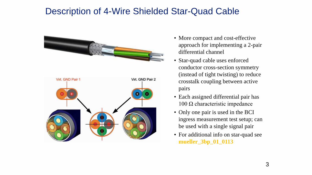
Description of 4-Wire Shielded Star-Quad Cable
• More compact and cost-effective
approach for implementing a 2-pair
differential channel
• Star-quad cable uses enforced
conductor cross-section symmetry
(instead of tight twisting) to reduce
crosstalk coupling between active
pairs
• Each assigned differential pair has
100 Ω characteristic impedance
• Only one pair is used in the BCI
ingress measurement test setup; can
be used with a single signal pair
• For additional info on star-quad see
mueller_3bp_01_0113
4
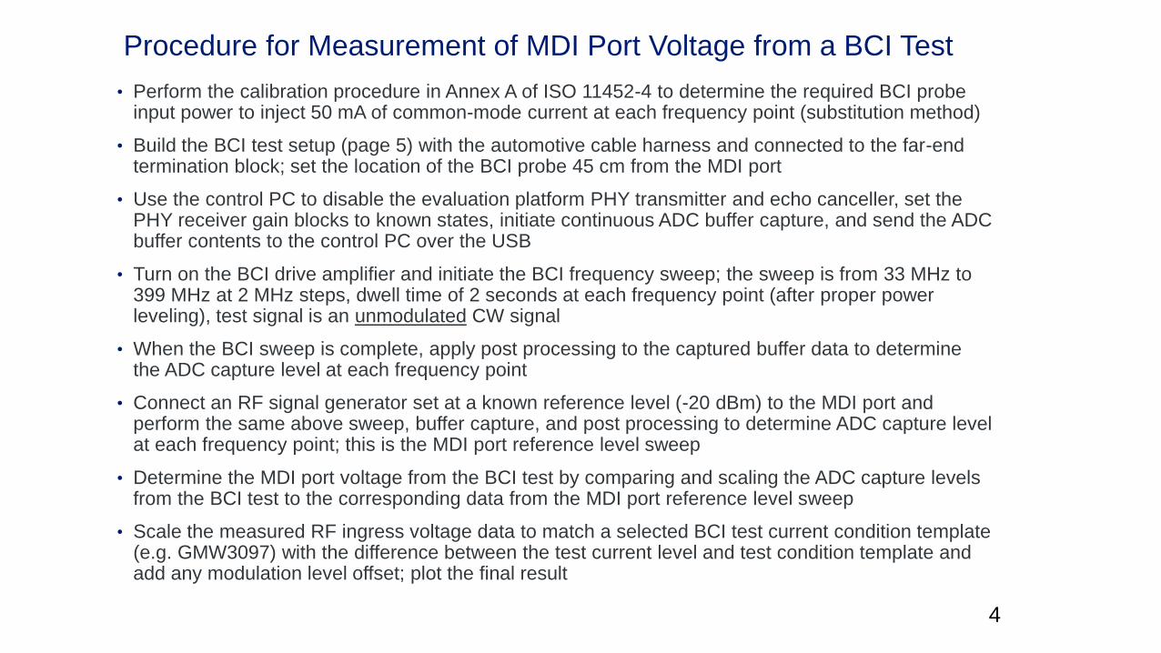
Procedure for Measurement of MDI Port Voltage from a BCI Test
• Perform the calibration procedure in Annex A of ISO 11452-4 to determine the required BCI probe input power to inject 50 mA of common-mode current at each frequency point (substitution method)
• Build the BCI test setup (page 5) with the automotive cable harness and connected to the far-end termination block; set the location of the BCI probe 45 cm from the MDI port
• Use the control PC to disable the evaluation platform PHY transmitter and echo canceller, set the PHY receiver gain blocks to known states, initiate continuous ADC buffer capture, and send the ADC buffer contents to the control PC over the USB
• Turn on the BCI drive amplifier and initiate the BCI frequency sweep; the sweep is from 33 MHz to 399 MHz at 2 MHz steps, dwell time of 2 seconds at each frequency point (after proper power leveling), test signal is an unmodulated CW signal
• When the BCI sweep is complete, apply post processing to the captured buffer data to determine the ADC capture level at each frequency point
• Connect an RF signal generator set at a known reference level (-20 dBm) to the MDI port and perform the same above sweep, buffer capture, and post processing to determine ADC capture level at each frequency point; this is the MDI port reference level sweep
• Determine the MDI port voltage from the BCI test by comparing and scaling the ADC capture levels from the BCI test to the corresponding data from the MDI port reference level sweep
• Scale the measured RF ingress voltage data to match a selected BCI test current condition template (e.g. GMW3097) with the difference between the test current level and test condition template and add any modulation level offset; plot the final result
5
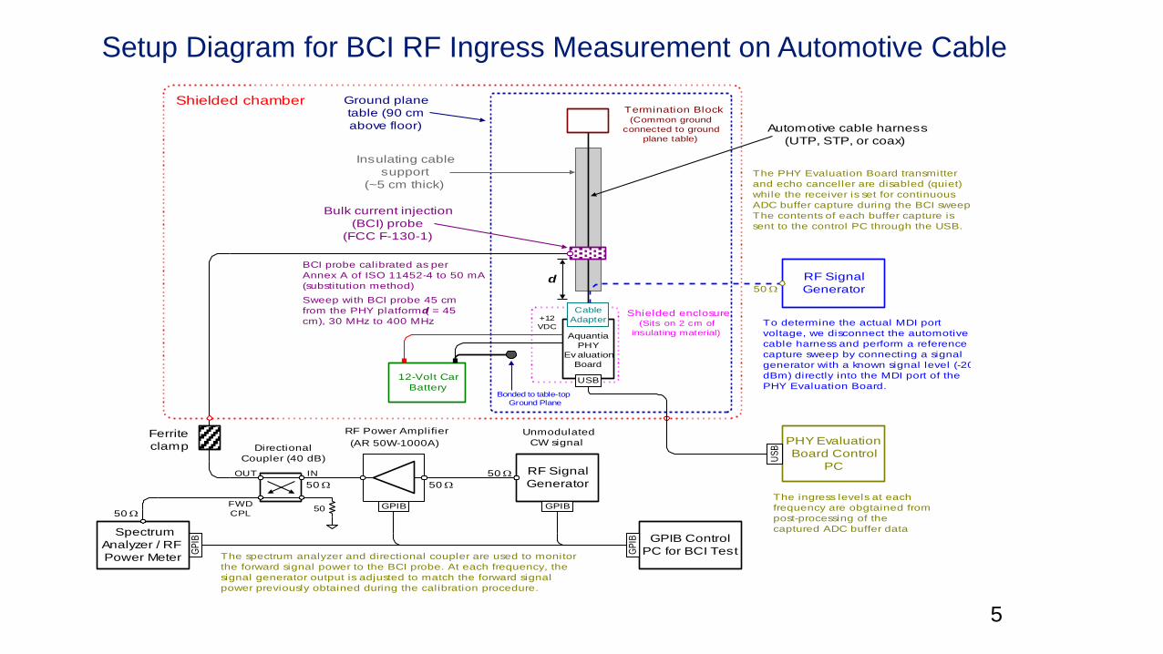
Setup Diagram for BCI RF Ingress Measurement on Automotive Cable
Aquantia
PHY
Ev aluation
Board
Ground plane
table (90 cm
above floor)
GP
IB
RF Power Amplifier
(AR 50W-1000A)
Shielded chamber
RF Signal
Generator50
50
GPIB GPIB
50
Insulating cable
support
(~5 cm thick)
Bulk current injection
(BCI) probe
(FCC F-130-1)
Ferrite
clamp
INOUT
50
Directional
Coupler (40 dB)
FWD
CPL
Spectrum
Analyzer / RF
Power Meter
50
GPIB Control
PC for BCI TestGP
IB
PHY Evaluation
Board Control
PC
US
B
Automotive cable harness
(UTP, STP, or coax)
The spectrum analyzer and directional coupler are used to monitor
the forward signal power to the BCI probe. At each frequency, the
signal generator output is adjusted to match the forward signal
power previously obtained during the calibration procedure.
Unmodulated
CW signal
USB
Cable
Adapter
d
Shielded enclosure(Sits on 2 cm of
insulating material)
BCI probe calibrated as per
Annex A of ISO 11452-4 to 50 mA
(substitution method)
Sweep with BCI probe 45 cm
from the PHY platform (d = 45
cm), 30 MHz to 400 MHz
The PHY Evaluation Board transmitter
and echo canceller are disabled (quiet)
while the receiver is set for continuous
ADC buffer capture during the BCI sweep.
The contents of each buffer capture is
sent to the control PC through the USB.
Termination Block(Common ground
connected to ground
plane table)
+12
VDC
12-Volt Car
Battery
To determine the actual MDI port
voltage, we disconnect the automotive
cable harness and perform a reference
capture sweep by connecting a signal
generator with a known signal level (-20
dBm) directly into the MDI port of the
PHY Evaluation Board.
The ingress levels at each
frequency are obgtained from
post-processing of the
captured ADC buffer data
RF Signal
Generator50
Bonded to table-top
Ground Plane
6
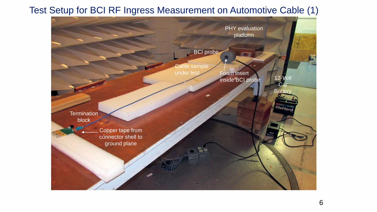
Test Setup for BCI RF Ingress Measurement on Automotive Cable (1)
Isolation
transformer
BCI probe
Termination
block
PHY evaluation
platform
Cable sample
under test
Termination
block
BCI probe
PHY evaluation
platform
Cable sample
under test12-Volt
Car
Battery
Copper tape from
connector shell to
ground plane
Foam insert
inside BCI probe
7
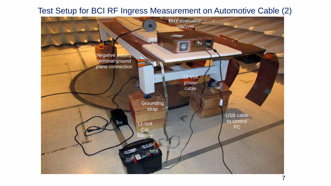
Test Setup for BCI RF Ingress Measurement on Automotive Cable (2)
Isolation
transformer
BCI probe
Termination
block
PHY evaluation
platform
Cable sample
under test
Termination
block
BCI probe
PHY evaluation
platform
Cable sample
under test12-Volt
Car
Battery
Copper tape from
connector shell to
ground plane
PHY evaluation
platform
12-Volt
Car
Battery
Negative battery
terminal ground
plane connection
12-Volt
power
cable
USB cable
to control
PC
Grounding
strap
8
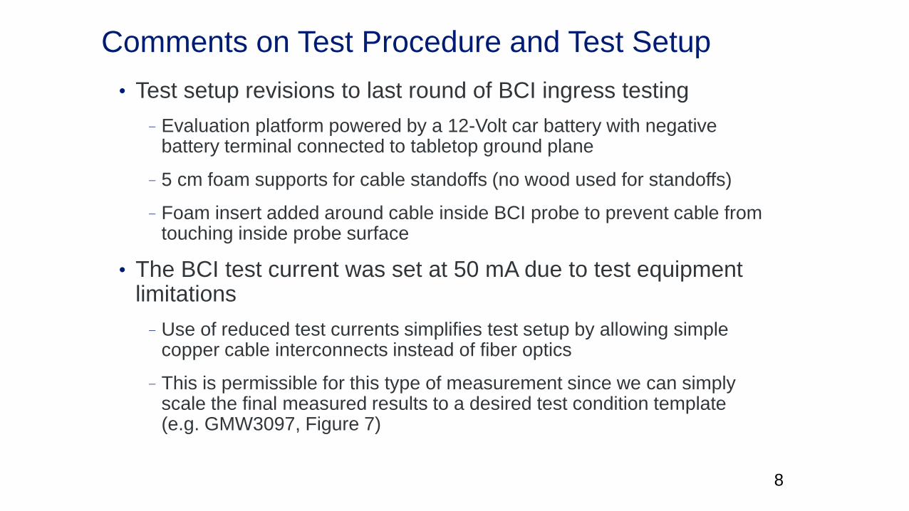
Comments on Test Procedure and Test Setup
• Test setup revisions to last round of BCI ingress testing
–Evaluation platform powered by a 12-Volt car battery with negative battery terminal connected to tabletop ground plane
–5 cm foam supports for cable standoffs (no wood used for standoffs)
–Foam insert added around cable inside BCI probe to prevent cable from touching inside probe surface
• The BCI test current was set at 50 mA due to test equipment limitations
–Use of reduced test currents simplifies test setup by allowing simple copper cable interconnects instead of fiber optics
–This is permissible for this type of measurement since we can simply scale the final measured results to a desired test condition template (e.g. GMW3097, Figure 7)
7/3/20179
7/3/201710
11
Observations and Next Steps
• Observations
–The observed RF ingress coupling from the STP cable samples is significantly less than double-shielded coaxial cable
–Star-quad with a single active pair has similar ingress level to single pair STP
–The observed RF ingress coupling from both STP cable samples is similar to the RF ingress level observed for Cat 6A UTP cabling in a 10 V/meter field
–The different peak/null pattern in the UTP measurement is due to the longer cable sample that was tested (5m for UTP vs. 1.9m for coaxial cable samples)
• Next steps
–Perform RF ingress measurements on multi-segment connectorizedchannels

Thank you.