an experimental investigation of the effects of diode
TRANSCRIPT
An experimental investigation of the effects of diode laser surface hardening of AISI 410 stainless steel and comparison with furnace hardening heat treatment Moradi, M., Arabi, H. & Kaplan, A. F. H. Author post-print (accepted) deposited by Coventry University’s Repository
Original citation & hyperlink:
Moradi, M, Arabi, H & Kaplan, AFH 2019, 'An experimental investigation of the effects of diode laser surface hardening of AISI 410 stainless steel and comparison with furnace hardening heat treatment', Journal of the Brazilian Society of Mechanical Sciences and Engineering, vol. 41, 434. https://doi.org/10.1007/s40430-019-1925-2 DOI 10.1007/s40430-019-1925-2 ISSN 1678-5878 ESSN 1806-3691 Publisher: Springer
The final publication is available at Springer via http://dx.doi.org/10.1007/s40430-019-1925-2 Copyright © and Moral Rights are retained by the author(s) and/ or other copyright owners. A copy can be downloaded for personal non-commercial research or study, without prior permission or charge. This item cannot be reproduced or quoted extensively from without first obtaining permission in writing from the copyright holder(s). The content must not be changed in any way or sold commercially in any format or medium without the formal permission of the copyright holders. This document is the author’s post-print version, incorporating any revisions agreed during the peer-review process. Some differences between the published version and this version may remain and you are advised to consult the published version if you wish to cite from it.

1
An experimental investigation of the effects of diode laser surface
hardening of AISI 410 stainless steel and comparison with furnace
hardening heat treatment
Mahmoud Moradi1, 2*, Hossein Arabi1, 2, Alexander F.H. Kaplan3
1- Department of Mechanical Engineering, Faculty of Engineering, Malayer University, P.O.
Box 65719-95863 Malayer, Iran
2- Laser Materials Processing Research Centre, Malayer University, Malayer, Iran.
3- Department of Engineering Sciences and Mathematics, Lulea University of Technology,
971 87, Lulea, Sweden
Email: [email protected], [email protected], 3 [email protected]
Abstract
This study investigated the ability of the continues wave diode laser surface hardening
on AISI 410 martensitic stainless steel with a maximum power of 1600 W. Variable process
parameters; scanning speed (4-7 mm/s), laser power (1200-1600 Watts) and stand-off distance
(65-75mm) were considered in this study. Micro-hardness, the geometry of hardened layer
(depth and width), micro-hardness deviation from the base metal micro-hardness (MHD),
microstructure analysis of the laser-hardened zone through optical microscopy (OM) and field
emission scanning electron microscopy (FE-SEM) and percentage of the ferrite phase in AISI
410 microstructure by using clemex software were considered as process output responses.
Results confirmed that by increasing the laser power and reducing the scanning speed, the
surface hardness and depth of hardness increase. It is also revealed the width of the hardened
area increases by enhancing in stand-off distance and reduction the laser power. Maximum
hardness of 630 HV0.3 with 2.2 mm depth is obtained. Also, the furnace hardening heat
treatment compared with the laser hardening process. Microstructure, microhardness, and
impact test of the two processes are compared. Results showed that the hardness of the diode
laser is 1.4 times the hardness of the furnace hardening heat treatment.
Keywords: Laser surface hardening; Diode laser; Microhardness; AISI410 martensitic
stainless steel; Microhardness deviation.

2
1. Introduction
To improve surface properties of materials, especially steels, which are widely used in
industry, traditional heat treatment methods are very popular, but modern methods like laser
surface treatment are more precise [1]. Laser processing is used for various applications such
as laser welding, brazing, and hardening [2-7], laser drilling [8], and laser cutting [9]. The
diode lasers are one of the most used and advanced lasers in the modern industry. This type of
laser with high accuracy heat-treated the surface of the matter. Martensitic stainless steels are
used in several industries including petroleum, gas and petrochemical, food and
pharmaceutical. These alloys are used in manufacturing corrosion resistance pipes and plates
and applied in an acidic environment which are more economical than similar grades [10].
One type of martensitic stainless steels widely used in industry is AISI 410 from 400 series of
these steels. Surface hardening is one of the laser surface treatment processes in which the
laser is selected with preset parameters. These parameters are variables depends on the type of
laser and material to be treated. After selecting optimum parameters, laser hardening
accomplishes, and surface hardness of steel improves which transformation of ferrite and
austenite phase to martensite will lead to more hardness [11]. Mahmoodi et al. [12] carried
out laser surface treatment of AISI 420 by means of Nd:YAG laser in pulsed module, which
in their research micro-hardness in depth and width of hardened area were studied. To
compare the ability of CO2 laser and diode laser in hardening of AISI 1045, Li et al. [13]
investigated the effect of each process on quality of the surface hardening. According to
experimental data of laser hardening by these two types of lasers, they simulated the process,
which showed the quality achieved by high power diode laser was higher than the one by CO2
laser. Guarino et al. [14] were used a high-power diode laser to develop the fatigue life of
AISI 1040 steel. Results revealed that laser treatment could considerably increase the fatigue
life. Netprasert et al. [15] studied to harden the AISI 420 martensitic stainless steel by using a
nanosecond pulse laser. The results showed that the micro-hardness increased from 242 HV to
1700 HV and depth of the hardened layer was created to be 60-80 µm. Yazici et al. [16]
investigated the effect of different processing temperatures on wear properties of high power
diode laser on R260 grade rail steel. Martinez et al. [17] surveyed the effects of the distinctly
applied laser heat treatment (LHT) and ultrasonic impact treatment (UIT) and the joined
LHT + UIT process on the wear and friction behaviors of the hardened surface layers of the
tool steel AISI D2. Syed et al. [18] studied effects of surface hardening by using a high power

3
diode laser. On C-Mn low carbon automotive steel. N. Barka et al. [19] were Investigated a
simulating model (finite difference method) and experimental method for laser hardening of
4340 steel. Telasang et al. [20] were investigated properties of corrosion resistance and wear
of AISI H13 steel, which hardened up to 800 Vickers. Fahdil Idan et al. [21] compared the
effects of CO2 laser hardening and tempering of 40, 40Cr and 38Cr2MoAl steels in GOST
Russian standard. Saftar et al. [22] investigated the effects of beam geometries (circular,
inverse triangle, rectangular beams) by using high power diode laser on the laser surface
hardening process. Moradi et al. [23] studied on laser surface hardening of AISI 410 by using
a 700 watts Nd:YAG laser in which the effect of laser pulse energy and focal point position
on geometrical dimensions and microhardness of hardened zone was investigated. Jahromi et
al. [24] investigated a study by Nd:YAG laser on the three different microstructures of AISI
410 martensitic stainless steel samples were heat treated including: fine ferrite, fine and
coarse martensite. Furthermore, finite element simulation was done using ABAQUS software
to predict diffusion on the hardness of the different microstructures by using Nd:YAG laser.
A mathematical model for Nd:YAG laser surface hardening of 42CrMo steel was presented
by using finite element method and verified by experimental results by sun et al. [25]. Ehlers
at al. [26] carried out laser surface hardening of AISI 4140 steel sheet by using a 2000W
diode laser. The maximum hardness reached to 740 HV with 1.9 mm depth in this study.
In spite of the efforts of these and other researchers, investigation on diode laser
hardening of AISI 410 martensitic stainless steel has not survived before. The use of diode
lasers to increase the depth and with of hardness, as well as hardness uniformity in the
hardened area, is considered as an effective challenge in other lasers, including the Nd:YAG
laser, which was previously written by the authors of this paper. In this study, the effect of
laser power, scanning speed and the stand-off distance (SOD) on the surface hardness and
geometric dimensions of the hardened area of AISI 410 were studied by using diode laser.
The microstructure changes of the steel surface were also measured and investigated. The
microstructure of the hardened area was evaluated. Also, the microstructure and mechanical
properties of furnace heat treatment were compared with the diode laser surface hardening.
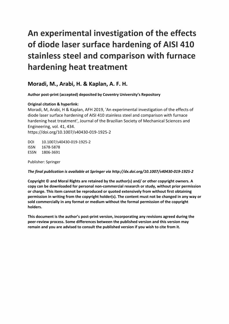
Figure 1 depicts the cross-section and geometrical responses of the hardened zone. The
microstructure of the hardened area surveyed by an OM and FESEM device. MHD and the
percentage of the ferrite phase in the structure investigated.
4
Figure.1 Specimen cross-section and geometrical responses of the hardened zone.
2. Experimental work
The chemical composition of AISI 410 stainless steel used in this research is mentioned
in Table 1. The chemical composition measured by atomic spectroscopy. The specimens with
(Specifications of the thickness =10 mm and the diameter = 65 mm) were selected.
Table1 Chemical composition (Wt. %) of AISI 410
Element
Name C Mo Cr Cu S P Mn Ni Si Al V Fe
Weight
percent 0.15 0.03 13.5 0.11 0.024 0.018 0.51 0.12 0.28 0.008 0.021 Balance
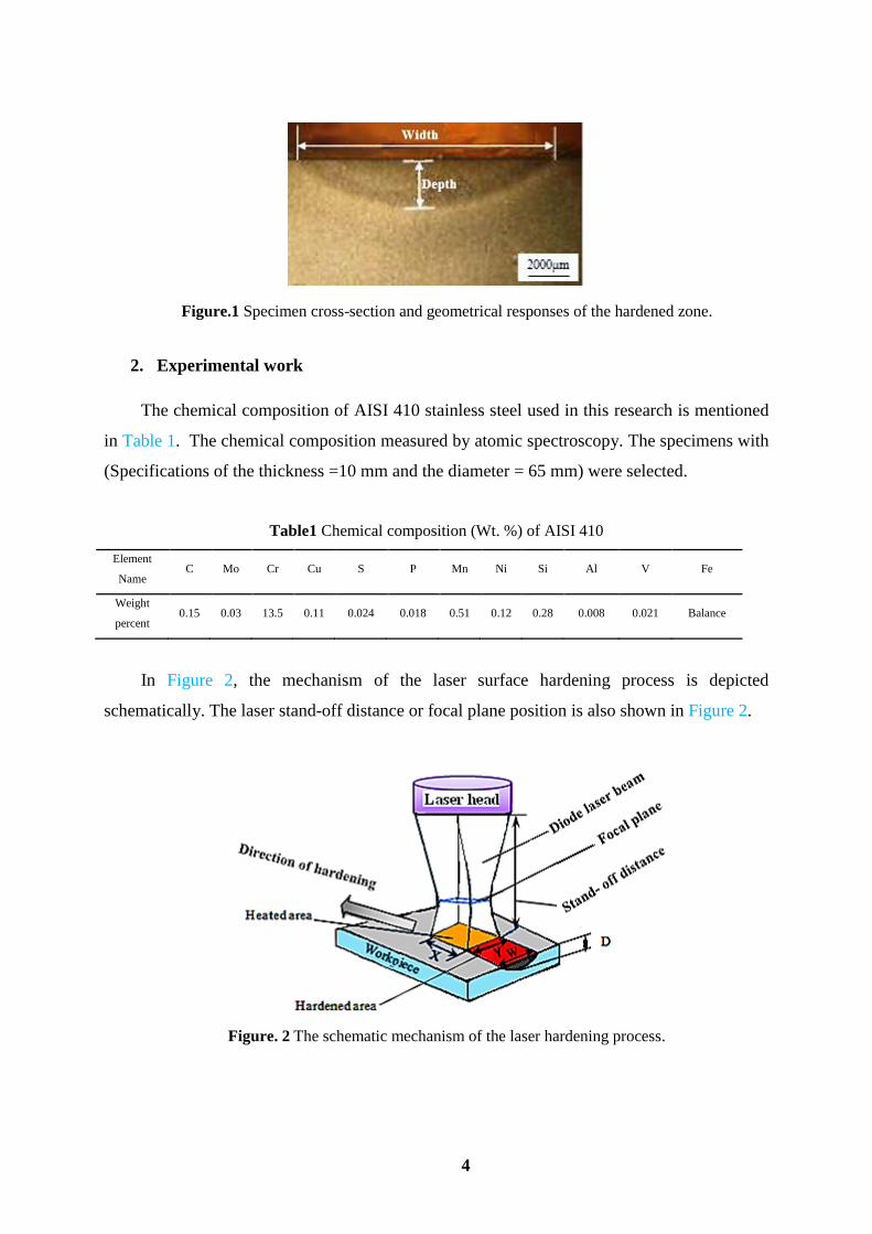
In Figure 2, the mechanism of the laser surface hardening process is depicted
schematically. The laser stand-off distance or focal plane position is also shown in Figure 2.
Figure. 2 The schematic mechanism of the laser hardening process.

5
Table. 2 Experimental layout and outcomes
A diode laser with a maximum power of 1600 W was used as a heat source for this
research. Experimental settings and outcomes of laser hardening process by diode laser is
shown in Table 2. Scanning speed (4-7 mm/s), laser power (1200 – 1600 W), and stand-off
distance (65-75 mm) were considered as input variables. Table 3 shows the different
dimensions of the incidence beam with a different focal plane position used in this research.
Table 3 The relationship between the incident beam length, width, and area
Stand-off distance Incident beam length (x) Incident beam width (y) Incident beam area (x-y)
65 mm 2.55 mm 9.94 mm 25.34 mm2
70 mm 3.60 mm 11.88 mm 42.77 mm2
75 mm 4.65 mm 13.82 mm 64.30 mm2
In Figure 3, images of AISI 410 samples hardened by diode laser are shown. To
investigate the microstructure of the hardened area, the samples are firstly cut into specific
pieces and by mounting and metallurgical preparations they have been etched in the villa's
reagent with a formula of ( Hcl 5cc, C6H3N3O7 2 gr, C2H5OH 100cc). Then, OM and
FESEM Images are taken. Microhardness was accomplished by a micro-indentation device
with a maximum load of 300 gr and a dwell time of 30 s. The geometric dimensions (depth
and width) of the hardened area were obtained. Figure 1 shows the depth and width of
hardness as a macroscopic structure. The Precision measurement of hardened dimensions was
done by ImageJ software. Figure 4 illustrates the cross-sectional view of Vickers indenters in
Sample Input parameters Output results
number Scanning
speed
(mm/s)
stand-off
distance (mm)
Laser
power
(W)
Maximum
hardness
(HV)
The depth of
hardness
(mm)
The width
of hardness
(mm)
MHD in
depth
MHD in
width
Ferrite
percent (%)
1 5 65 1400 630 2.2 8.12 18813.71 28651.62 0.52
2 6 70 1200 490 1.4 8.42 12399.23 16417.13 1.92
3 4 70 1200 540 1.7 8.33 16211.64 21364.23 0.71
4 6 70 1600 620 1.8 8.21 18658.42 26621.61 0.62
5 7 65 1400 530 1.6 8.41 16053.43 20813.71 1.10
6 5 75 1400 520 1.5 8.52 15311.97 18355.25 1.50

6
depth and width of the hardened layer. The interval of the points in depth and width are
100µm and 300µm, respectively.
Figure. 3 Image of the hardened laser samples (sample diameter is 65mm)
Figure. 4 Image of Vickers indenters
3. Results and discussion
In this research, the effects of diode laser parameters (i.e., scanning speed, laser power,
and stand-off distance) on AISI 410 martensitic stainless steel in surface hardening process
was studied. To investigate the metallurgical properties, geometrical dimensions of the
hardened area, microhardness distribution of the laser hardening, microstructure on the
hardened surface, MHD and the percentage of the ferrite phase in the structure were analyzed.
3.1 Micro-hardness distribution
Figure 5-a and 5-b show the micro-hardness changes from the surface to the depth and
width of samples 1, 4 and 5.

7
Figure.5 Micro-hardness profile of the hardened layer in a) depth and b) width.
In Figure 5-a it is clear that surface hardness is increased and little by little is decreased
along the depth of the hardened zone to reach the base metal hardness. It is because of the
reduction of transferred laser energy in the material. Fine grain martensitic and ferrite phase
dispersed in the hardened area. It is because of the high rate of quenching during laser
hardening process, which produces unique metallurgical effects in the steel, such as
improvement of microstructure and grain size, higher hardness with appropriate toughness in
the steel. Figure 5-b depicts the microhardness distribution of the hardened layer in width. It
is displayed in half of the width of the hardened zone. As it is clear, its distribution likes a
sinusoidal function that in the hardness is the maximum in the center and decreases gradually
in the outside of the hardened area. The reason for this phenomenon is the rectangular energy
distribution of the laser beam that is illustrated in Figure 6.

8
Figure 6-a and 6-b depict the images of the energy distribution in the diode laser beam
and the shape of top-hat energy distribution, respectively [27]. Maximum surface hardness
occurs in sample number 1 equal to 630 HV0.3 hardness. It means that the surface hardness
increases 90% from 330 HV of the base metal.
Figure. 6 a) distribution of the diode laser beam energy, b) the shape of top-hat energy distribution
[27-28].
To improve the results of the laser hardening process, the following parameters should
be carefully considered:
1. The amount of heat entering the laser beam to the surface of the material.
1. The effect of metallurgical factors on the microstructure of the hardened area, such as
grain size.
At first, the effect of heat input on the workpiece surface is studied. Equation 1 shows the
laser heat input to the surface [29].
H = P / S (1)
Therefore, by increasing the power of the laser beam and reducing the scanning speed on the
workpiece, the heat input increases. Increases in the heat input lead to increases the hardness,
while for Sample #1, Sample #4 and Sample #5 the heat input are 280 (j/mm), 266.6 (j/mm)
and 200 (j/mm) respectively. The grain size of the laser hardened zone is an important issue
for considering. The ASTM-112 standard is used to measure the grain size. To specify the
grain size, the usual heat treatment cycle should be initiated at 850 ° C for one hour and then
cooled at the furnace temperature. After achieved the declared heat treatment with a suitable

9
etching solution, the initial austenite particle, which is a solid solution of carbon and is stable
at high temperatures is studied. Indeed, by measuring the size of the initial austenite, by using
the Nital solution (2 ml Nitric acid and 98 ml Ethanol alcohol) the grain size is estimated [30].
For the base metal of the AISI 410, ASTM grain size number =7 (Equal to 30µm) reach to
ASTM grain size number =11 (Equal to 7µm). By reducing the size of the initial austenitic
grains, the structure is susceptible to the formation of a smaller martensitic phase during the
process of austenite transformation into martensite. As the particle size of the martensite
increases, the hardness of the surface of the hardened area increases. The Hall-Petch equation
[30-31] presents the relationship between the size of the grain in the microstructure and the
mechanical properties. Equation 2 describes Hall-Petch's relation:
(2)
Where 𝜎𝑖 is yield stress, 𝜎0 is the friction stress, K is the locking parameter and D is the mean
diameter of the grain. Due to reduced grain size, the strength of the material and mechanical
properties improve.
3.2 Geometrical dimensions of the hardened layer
As it is discussed above for Figure 6, the shape of the geometrical dimensions of the
hardened zone is similar to the form of the laser energy distribution. By increasing the stand-
off distance, the laser beam diverges, and the energy density is decreased, and a spot diameter
of the laser becomes larger. In this paper increasing the stand-off distance (SOD) means
getting away from The focal plane which is affected by penetration depth and also the
hardness. Figure 7-a illustrates the effect of SOD on the distribution of the hardness in depth
of the hardened zone. It is showed that in sample # 1 (SOD =65mm) the trend of hardness is
higher than sample # 6 (SOD =75mm). The reason is that by decreasing the distance between
the spot plane of the laser and workpiece, causes more energy induced in metal. It leads to
increase the metallurgical transformation and causes more hardness. By focusing on the
results presented in Table 2, it can understand that increasing the laser power causes increases
in the depth of the hardened layer. More laser power leads to increases the austenitic
temperature. So the micro-hardness and geometrical dimensions increases (compare samples
# 4 and samples # 2). Figure 7-b illustrates the influence of the laser power on the hardness
distribution in depth of the hardened layer. Scanning speed has a direct effect on the laser
hardening results. Decreasing scanning speed increases the interaction time between the laser
𝜎0 = 𝜎𝑖 + 𝐾𝐷−12⁄

10
beam and the workpiece. Therefore, heat input energy to the material increases which leads
increase the hardness and geometrical dimensions of the hardened layer.
Figure.7 Image of microhardness profile for Depth of the hardened area, a) effect of stand-off
distance, b) effect of laser power, c) effect of scanning speed.
Influence of scanning speed could be seen in samples # 5 and samples # 2 (see Table 2).
Figure 7-c illustrates the influence of scanning speed on the hardness distribution in depth of
the hardened layer. In the following discussion, the influence of three other important
parameters that have an important influence on the geometric dimensions is presented. These
parameters are Beam density of the diode laser, the shape of the distribution of energy beam in
diode laser and metallurgical properties such as the form of the phases in the microstructure,
which is described below. The energy beam density of the diode laser is shown in Equation 3
[3].
Beam density = Laser power / Incident beam area (3)
By increasing the density of the energy beam, the surface temperature of the workpiece
increases. Then the austenitic temperature rises, so hardness and the depth of the hardened
area are increased. Table 2 and 3 present the incident beam area and the laser power. By using
Equation 3, the beam density is calculated, for sample #1 and sample #6 as shown in Figure
7-a, the beam densities are, 55.25 W/mm2 and 21.77 W/mm2, respectively. Therefore, with
more beam density in sample #1, the geometric dimensions (depth and width) of the hardened
11
area will greater. According to Figure 7-b, the beam density of sample #4 and sample #2 are
37.40W/mm2 and 28.05 W/mm2, respectively. The reason for the increase in the geometric
dimensions (of the hardened area) in sample #4, compared to the sample #2, is the increase in
the beam density of sample #4. in Figure 7-c, both sample #5 and sample #2 have the same
beam density, but because of increasing the heat input in sample #5 than sample #2 the
geometric dimensions will be increased.
As shown in Figure 6, the form of the energy distribution in the diode laser is
rectangular. This top-hat distribution of energy leads to the expansion of the heat affected
area, and the hardened area becomes larger, so the geometric dimensions of the hardened area
are larger than another laser beams that are in the form of a gaussian distribution, such as
(Nd:YAG laser and fiber laser). In addition when the shape of the particles is extended in the
microstructure, the thermal conductivity and laser penetration increase, so the geometric
dimensions of the hardened area increase. What concluded from the microstructure images is
that ferrite particles are stretched; therefore, the penetration of the thermal energy of diode
laser in depth and width of the workpiece increases.
3.3 Microstructure of hardened layer
To study the effect of laser hardening process on the microstructure of the material, the
metallographic survey is performed by using optical microscopy (OM) and field emission
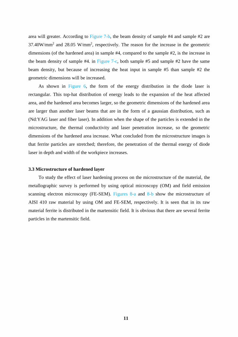
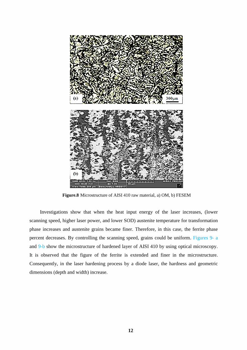
scanning electron microscopy (FE-SEM). Figures 8-a and 8-b show the microstructure of
AISI 410 raw material by using OM and FE-SEM, respectively. It is seen that in its raw
material ferrite is distributed in the martensitic field. It is obvious that there are several ferrite
particles in the martensitic field.
12
Figure.8 Microstructure of AISI 410 raw material, a) OM, b) FESEM
Investigations show that when the heat input energy of the laser increases, (lower
scanning speed, higher laser power, and lower SOD) austenite temperature for transformation
phase increases and austenite grains became finer. Therefore, in this case, the ferrite phase
percent decreases. By controlling the scanning speed, grains could be uniform. Figures 9- a
and 9-b show the microstructure of hardened layer of AISI 410 by using optical microscopy.
It is observed that the figure of the ferrite is extended and finer in the microstructure.
Consequently, in the laser hardening process by a diode laser, the hardness and geometric
dimensions (depth and width) increase.

13
Figure.9 The microstructure of AISI 410 laser hardened layer (OM), a) sample #1, b) sample#4
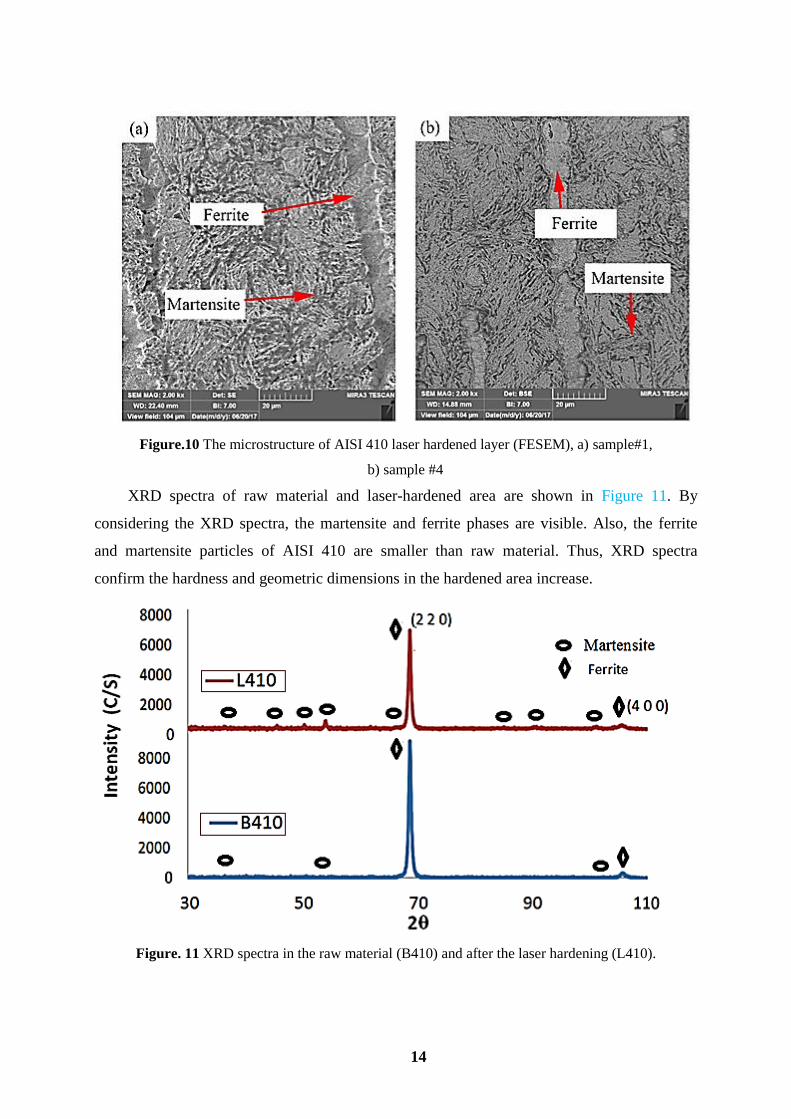
Figures 10-a and 10-b illustrate the microstructure of the hardened layer of Sample #1
and sample #4, respectively. These images are taken by using the FE-SEM. Due to higher laser
energy, martensitic particles are finer, and ferrite particles are dissolved in the structure fields.
Therefore, laser hardening has caused higher surface hardness, more uniform and suitable
structure. It is observed that the ferrites are stretched and martensites are stretched and needle-
shaped in the structure. Thus, laser hardening caused major changes in the size of the
martensitic phase and the dissolution of the ferrites.
14
Figure.10 The microstructure of AISI 410 laser hardened layer (FESEM), a) sample#1,
b) sample #4
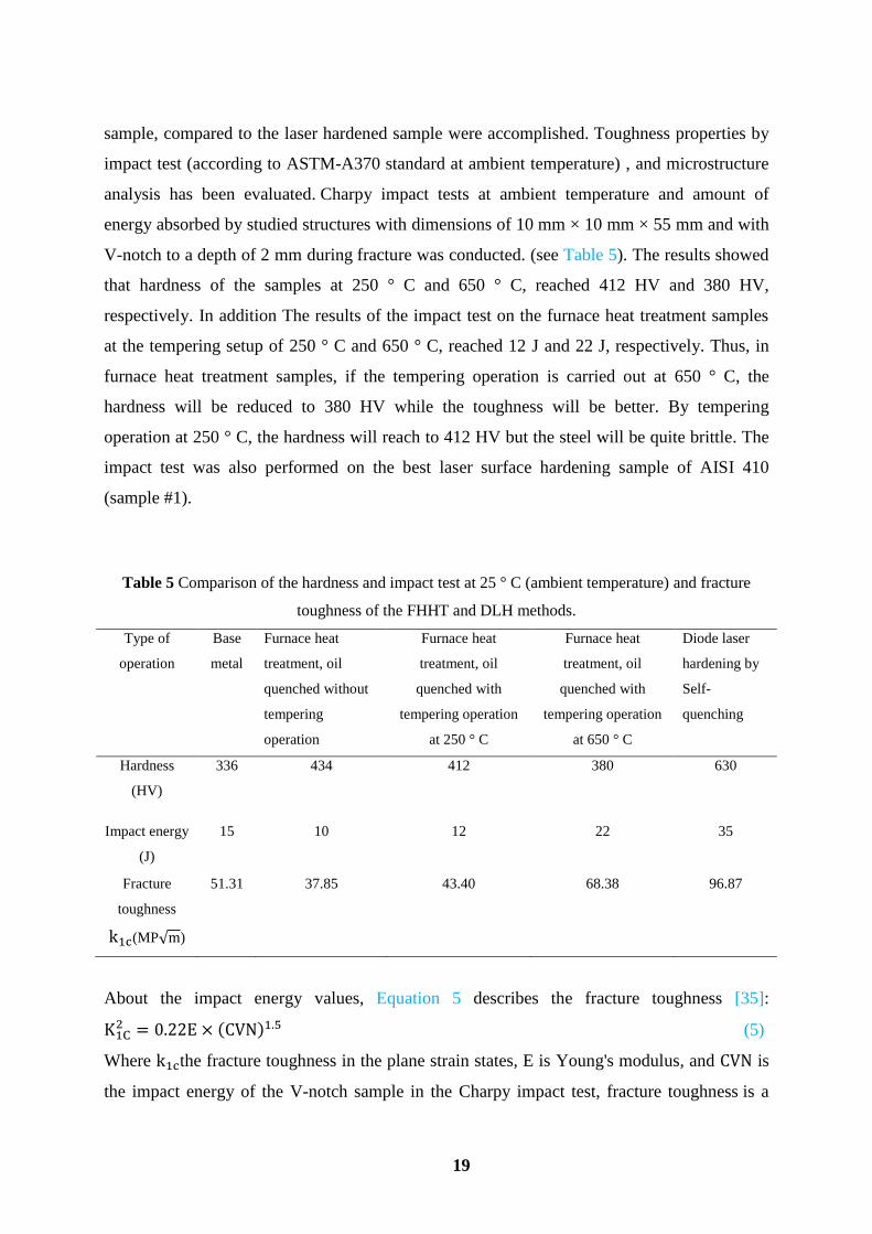
XRD spectra of raw material and laser-hardened area are shown in Figure 11. By
considering the XRD spectra, the martensite and ferrite phases are visible. Also, the ferrite
and martensite particles of AISI 410 are smaller than raw material. Thus, XRD spectra
confirm the hardness and geometric dimensions in the hardened area increase.
Figure. 11 XRD spectra in the raw material (B410) and after the laser hardening (L410).

15
3.4 Microhardness deviation from the base metal (MHD)
To study how the microhardness distribution profile changes at the depth and width of
the hardened area, the parameter of MHD is used according to Equation 4 [32].
MHD = ∑(Xi−Xb.m)2
n
ni=1 (4)
Where Xi is the microhardness of point i and Xb.m is raw metal microhardness, n is the
number of measured microhardness points. In the present research, n is 10 and Xb.m equal 330
wickers for AISI 410 stainless steel. Higher MHD in the laser hardening is more desirable.
MHD is one of the most important output parameters in this study. Indeed, MHD designates
the uniformity of hardness in the hardened area.
3.5 The percentage of the ferrite phase
By analyzing images of the microstructure using celemex software, the amount of ferrite
phase particles in the structure of the hardened samples was obtained. The results are
presented in Table 2. The existence of ferrite in the hardened area reduces the hardness and
strength of the steel. Microstructure images of the hardened surface were selected along the
center of the hardened area. In Figure 12-a and 12- b the red dots represent the ferrite phase
and the blue field indicating martensites. As shown in Table 2, in Figure 12-a, the percentage
of ferrite is lower than that of Figure 12-b, The reason is that sample number #1 has a higher
heat input energy (higher laser power and lower stand-off distance). Thus by increasing the
laser thermal energy, the steel's austenitic temperature rises and the ferrites phases are solved
in the structure. Figure 13 depicts the relationship of ferrite percentage with the maximum
surface hardness of samples. As seen, decreasing the ferrite percentage results in increasing
the maximum surface hardness.

16
Figure. 12 Determination of ferrite percentage by celemex software a) sample #1, b) sample #2
Figure.13 Profile of ferrite percent in microhardness.
3.6 Comparison of the furnace hardening heat treatment (FHHT) and diode laser
hardening (DLH)
In this section, FHHT was conducted to compare with the DLH method. For comparing
the DLH with the conventional method, the furnace heat treatment according to the cycle
presented in Figure 14 was performed. The AISI 410 samples preheated to 540 º C for 1 hour,

17
heated to 980 º C with the rate of 70 º C/hour, and were kept for 2 hours. Then samples
quenched with three ways (air, oil, and water-cooling).
Figure.14 Image of FHHT cycle for AISI 410 stainless steel [33].
3.6.1 Comparison of the hardness
Table 4 shows the comparison of the hardness results of furnace hardening heat
treatment and laser surface hardening. As seen in Table 4 the hardness of furnace hardened of
AISI 410 stainless steel quenched in the air, oil, and water are 412 Vickers, 434 Vickers, and
446 Vickers, respectively. Due to the possibility of micro crack formation in the water, and
the lower the hardness in the air, the oil is an ideal quenching method with a hardness of 434
Vickers for AISI 410. So the hardness value with the diode laser hardening method (630
Vickers) is 1.4 times than the furnace hardening heat treatment.
Table 4. Comparison of furnace hardening heat treatment and laser hardening
Heat treatment cycle furnace hardening heat
treatment laser hardening
Cooling in oil 434 Vickers -
Cooling in water 446 Vickers -
Cooling in air 412 Vickers -
Self-cooling (Self- quenching) - 630 Vickers
3.6.2 Comparison of the microstructure
As shown in Figure 15-a and 15-b the fine ferrites are dispersed in the rough martensitic
field of FHHT samples, while in the DLH, these elements are interconnected in the fine
martensitic field. Due to the high-energy concentration in the DLH, local hardness occurs,

18
while in the FHHT, the hardness is volumetric. The existence of ferrite in the martensite field
reduces the hardness and strength of the steel. Because of small interaction time in the laser
and high speed of the process, ferrites are detected in the martensite field. To reduce or
remove them, increase the laser power and slow down the scanning speed could overcome
this challenge. In FHHT technique because of keeping the sample at a specific time during the
heating cycle, in the microstructure, fine ferrite and rough martensite phases are observed.
Hence, in the FHHT technique the hardness increases, but this structure is brittle.
Figure.15 Microstructure images of the hardened sample a) FHHT, oil quenched b) DLH, sample #1
3.6.3 Comparison of the impact test and fracture toughness
According to the heat treatment cycle of Figure 14, AISI 410 is heated to 980 ° C, at this
temperature the microstructure consists of austenite and ferrite, then, with the quenching
operation, the sample is rapidly cooled, and the martensitic and ferrite particles are obtained
with a very tough structure. Quenching operation creates internal stresses as well as brittle
structures in steel. In this process, the hardness of the steel is higher, but the mechanical
properties are reduced. To improve the mechanical properties of steel, such as an increase in
toughness and a reduction in the residual stress after the quenching operation, the tempering
heat treatment cycle is performed. The temperature and time selection of tempering operations
depends on the chemical composition of the steel, the dimensions of the pieces and the
mechanical properties are required. Tempering is performed by controlled heating of the
quenched workpiece called the lower transformation temperature (Under the temperature of
723 ° C). This steel conducted relatively high hardness and strength after tempering at such
high temperature of 600-700°C [33]. In the present study, to investigation of the hardness and
toughness of The furnace heat treatment hardening samples, tempering sample with high
temperatures of 650°C, tempering sample with a minimum of 250°C [34] and No tempering
19
sample, compared to the laser hardened sample were accomplished. Toughness properties by
impact test (according to ASTM-A370 standard at ambient temperature) , and microstructure
analysis has been evaluated. Charpy impact tests at ambient temperature and amount of
energy absorbed by studied structures with dimensions of 10 mm × 10 mm × 55 mm and with
V-notch to a depth of 2 mm during fracture was conducted. (see Table 5). The results showed
that hardness of the samples at 250 ° C and 650 ° C, reached 412 HV and 380 HV,
respectively. In addition The results of the impact test on the furnace heat treatment samples
at the tempering setup of 250 ° C and 650 ° C, reached 12 J and 22 J, respectively. Thus, in
furnace heat treatment samples, if the tempering operation is carried out at 650 ° C, the
hardness will be reduced to 380 HV while the toughness will be better. By tempering
operation at 250 ° C, the hardness will reach to 412 HV but the steel will be quite brittle. The
impact test was also performed on the best laser surface hardening sample of AISI 410
(sample #1).
Table 5 Comparison of the hardness and impact test at 25 ° C (ambient temperature) and fracture
toughness of the FHHT and DLH methods.
Type of
operation
Base
metal
Furnace heat
treatment, oil
quenched without
tempering
operation
Furnace heat
treatment, oil
quenched with
tempering operation
at 250 ° C
Furnace heat
treatment, oil
quenched with
tempering operation
at 650 ° C
Diode laser
hardening by
Self-
quenching
Hardness
(HV)
336 434 412 380 630
Impact energy
(J)
15 10 12 22 35
Fracture
toughness
k1c(MP√m)
51.31 37.85 43.40 68.38 96.87
About the impact energy values, Equation 5 describes the fracture toughness [35]:
K1C2 = 0.22E × (CVN)1.5 (5)
Where k1cthe fracture toughness in the plane strain states, E is Young's modulus, and CVN is
the impact energy of the V-notch sample in the Charpy impact test, fracture toughness is a

20
property, which describes the ability of a material to resist fracture, and is one of the most
important properties of any material for many design applications. Fracture toughness is a
quantitative way of expressing a material's resistance to brittle fracture when a crack is
present. A material with high fracture toughness may undergo ductile fracture as opposed to
brittle fracture. According to Table 5, the result shows that diode laser hardening has higher
hardness and toughness than furnace hardening heat treatment. Having a higher hardness and
higher fracture toughness at the same time in laser surface hardening could improve the
application of this process, which could have so many applications in industries such as steam
turbine blade application. Figure 16-a, b and c show images of the microstructure of
tempering operation at 250°C and 650°C and diode laser hardening respectively. Fine
particles of ferrite and martensite exist in the structure of the tempered at 250°C, which causes
higher hardness and lower fracture toughness (See Figure 16-a). As shown in Figure 16-b, in
the tempered state at 650°C, the coarse ferrite and martensite particles has been scattered in
the microsructure, this can be lead to lower hardness and higher fracture toughness in the
AISI 410 hardened sample. In the diode laser hardening, as shown in Figure 16-c, finer
particles of ferrite and martensite can be seen which causes higher hardness and higher
fracture toughness.
Figure.16 Microstructure images of the tempering operation at a) 250°C b) 650°C
c) Diode laser hardening
4. Conclusions
The influences of diode laser parameters (i.e., laser power, scanning speed, and stand-off
distance) on AISI 410 martensitic stainless steel in surface transformation hardening process
was studied. Geometrical dimensions of the hardened layer, microhardness distribution in
depth and width of laser hardening and microstructure on the hardened surface were analyzed.
The following conclusions can be drawn:
1. Increasing the laser power and reducing scanning speed, (increasing heat input),
lead to increases in microhardness and depth of the hardened layer. Decreasing the

21
stand-off distance causes more energy induced to the material. Regarding
rectangular energy distribution of the laser beam, hardness, and depth of the
hardening layer increases.
2. The maximum surface hardness of 630 HV0.3 with the maximum depth of the
hardened layer of 2.2 mm is obtained. It means that the surface hardness increases
90% from 330 HV of the base metal.
3. The microhardness deviation (MHD) specifies the uniformity of hardness in the
hardened area, so, if the hardness decreases gradually from surface to depth, the
MHD in depth will be higher.
4. To reduce or eliminate ferrite phases, the lower scanning speed and the higher laser
power is recommended. Also in the laser hardening, ferrite particles are
interconnected in the microstructure. However, in the furnace hardening operation,
are finer and more dispersed.
5. The hardness value of the diode laser hardening method (630 HV0.3) is 1.4 times
than furnace hardening heat treatment.
6. The maximum hardness and impact energy values for the laser hardened samples
are 630 HV and 35 J, respectively. While these values for the furnace heat treatment
sample are 380 HV and 35 J, respectively.
5. References:
1. E. Kannatey, Jr. Asibu, Principles of Laser Materials Processing, Second Edition, pp. 568-
581, New Jersey: John Wiley and Sons, 2009.
2. M. Moradi, M. Karami Moghadam, M. Kazazi, Improved Laser Surface Hardening of AISI
4130 Low Alloy Steel with Electrophoretically Deposited Carbon Coating, Optik, Vol. 178
(February), pp. 614-622, 2019.
3. M. Moradi, M. Karami Moghadam, High power diode laser surface hardening of AISI
4130; statistical modeling and optimization, Optics & Laser Technology Vol. 111 (April),
pp.554-570, 2019.
4. A Khorram, A Jafari, M Moradi, Effect of Linear Heat Input on the Morphology and
Mechanical Properties of Ti-6Al-4V Welded Using a CO2 Laser, Lasers in Engineering, Vol
40 (1-3), pp. 49-64, 2018.
22
5. A. H. Faraji, M. Moradi, M. Goodarzi, P. Colucci, Carmine Maletta. An investigation on
the capability of hybrid Nd:YAG laser-TIG welding technology for AA2198 Al-Li alloy.
Optics and Lasers in Engineering.Vol. 96, PP.1-6. 2017.
6. A. khorram, A Jafari, M Moradi. Laser brazing of 321 and 410 stainless steels using BNI-2
nickel-based filler metal. Modares Mechanical Engineering, Vol.17 No. 1, pp. 129-135, 2017.
7. M. Moradi, M. Ghoreishi and A. Khorram. Process and Outcome Comparison between
Laser, Tungsten Inert Gas (TIG) and Laser-TIG Hybrid Welding. Journal of lasers in
Engineering, Vol 39, No. 3-6, pp. 379-391. 2018.
8. M. Moradi, A. Mohazabpak. Statistical modeling and optimization of laser percussion
micro-drilling on Inconel 718 sheet using response surface methodology. Journal of lasers in
Engineering, Vol 39, No. 4-6, pp. 313-331, 2018.
9. M. Moradi, Omid Mehrabi, Taher Azdast, Khaled Y Benyounis, Enhancement of low
power CO2 laser cutting process for injection molded polycarbonate, Optics & Laser
Technology, Vol. 96C, pp. 208–218,2017.
10. L. Li, “The advances and characteristics of high-power diode laser materials processing”,
Optics and Lasers in Engineering 34, pp. 231-253, 2000.
11. R. Puli, G. D. Janaki Ram, Wear and corrosion performance of AISI 410 martensitic
stainless steel coatings produced using friction surfacing and manual metal arc welding,
Surface and Coatings Technology, Vol. 209, No. 24, pp. 1-7, 2012.
12. B. Mahmoudi, A. R. Sabour Aghdam, M. J. Torkamany, Controlled laser transformation
hardening of martensitic stainless steel by pulsed Nd: YAG laser, Electronic Science and
Technology, Vol. 8, No. 01, pp. 87-90, 2010.
13. R. Li, Y. Jin, Zh. Li, K. Qi, A comparative study of high-power diode laser and CO2 laser
surface hardening of AISI 1045 steel, Materials Engineering and Performance, Vol. 23, No.
09, pp. 3085-3091, 2014.
14. S.Guarino, M.Barletta, A.Afilal, High Power Diode Laser (HPDL) surface hardening of
low carbon steel: Fatigue life improvement analysis, Journal of Manufacturing Processes, Vol
28, No.01, pp. 266-271, 2017.
15. O. Netprasert, V.Tangwarodomnukun , Ch.Dumkum, Surface Hardening of AISI 420
stainless Steel by Using a Nanosecond Pulse Laser, Materials Science Forum, Vol. 911, pp.
44-48, 2018.

23
16. O.Yazici, S.Yilmaz, Investigation of effect of various processing temperatures on abrasive
wear behaviour of high power diode laser treated R260 grade rail steels, tribology
International, Vol 119, pp. 222-229, 2018.
17. D. A. LesykS. Martinez, B. N. Mordyuk,V. V. Dzhemelinskyi, Lamikiz,G. I.
Prokopenko, K. E. Grinkevych, I. V. Tkachenko, Laser-Hardened and Ultrasonically Peened
Surface Layers on Tool Steel AISI D2: Correlation of the Bearing Curves’ Parameters,
Hardness and Wear,Journal of Materials Engineering and Performance, Vol 27, No 02, pp.
764–776, 2018.
18. B.Syed, S.M. Shariff, G.Padmanabham, Sh.Lenka, B.Bhattacharya, S .Kundu, Influence
of laser surface hardened layer on mechanical properties of re-engineered low carbon steel
heet, Materials Science and Engineering: A,Vol 685, pp. 168-177, 2017.
19. N.Barka, J.Brousseau, Case study of laser hardening process applied to 4340 steel
cylindrical specimens using simulation and experimental validation, Case Studies in Thermal
Engineering, Vol.11, pp. 15-25, 2018.
20. G. Telasang, J. D. Majumdar, G. Padmanabham, I. Manna, Wear and corrosion behavior
of laser surface engineered AISI H13 hot-working tool steel, Surface and Coatings
Technology, Vol. 261, No. 01, pp. 69-78, 2015.
21. A. Fahdil iidan, O. Akimov, L.Golovco, O.Goncharuk, K.Kostyk, The study of the
influence of laser hardening conditions on the change in properties of steel. Iadn; 2(5), pp. 69-
73, 2016.
22. Sh. Safdar, L. Li, M.A. Sheikh, M.J .Schmidt. Modelling the effect of laser beam
geometry on laser surface heating of metallic materials. Proceedings of the 23 International
Congress on Applications of Lasers and Electro-Optics, 2004.
23. M. Moradi, M. KaramiMoghadam, J. Zarei, B. Ganji. The effects of gha laser pulse
energy and focal point position on laser surface hardening of AISI 410 stainless steel.
Modares Mechanical Engineering. 17(7), pp. 311-318. 2017.
24. S.A. Jenabali Jahromi, A. Khajeh, B. Mahmoudi. Effect of different pre-heat treatment
processes on the hardness of AISI 410 martensitic stainless steels surface-treated using pulsed
neodymium-doped yttrium aluminum garnet laser. Materials and Design, 34, pp. 857–862,
2012.

24
25. P. Sun, Sh. Li, G. Yu, X. He, C. Zheng & W. Ning, “Laser surface hardening of 42CrMo
cast steel for obtaining a wide and uniform hardened layer by shaped beams”, Int J Adv
Manuf Technol, Vol. 70, pp.787–796. 2014.
26. B. Ehlers, H.J. Herfurth, S. Heinemann, Hardening and welding with high power diode
lasers, Proc. SPIE 3945, pp. 63–70. 2000.
27. R. Li, Y. Jin, Zh. Li, & K. Qi, A Comparative Study of High-Power Diode Laser and CO2
Laser Surface Hardening of AISI 1045 Steel, JMEPEG, Vol. 23, pp. 3085–3091, 2014.
28. M. Moradi, M.M. Fallah, S. Jamshidi Nasab, Experimental study of surface hardening of
AISI 420 martensitic stainless steel using high power diode laser, Transaction of the Indian
institute of metal, Springer Nature, pp.1-18, 2018.
29. E. Haddadi, M. Moradi, A. Karimzad Ghavidel, A. Karimzad Ghavidel, S. Meiabadi.
Experimental and Parametric Evaluation of Cut Quality Characteristics in CO2 Laser Cutting
of Polystyrene, Optik, Vol. 184, pp. 103-114, 2019.
30. B.Jung a, H.Lee b, H.Park, Effect of grain size on the indentation hardness for
polycrystalline materials by the modified strain gradient theory, International Journal of
Solids and Structures Vol 50, pp. 2719–2724, 2013.
31. X.Liu, F.Yuan, Y.Wei, Grain size effect on the hardness of nanocrystal measured by the
Nano- size indenter, Applied Surface Science Vol 279, pp. 159-166, 2013.
32. M. R. Jelokhani-Niaraki, N. B. Mostafa Arab, H. Naffakh-Moosavy, & M. Ghoreishi,
The systematic parameter optimization in the Nd:YAG laser beam welding of Inconel 625,
The International Journal of Advanced Manufacturing Technology. Vol. 84, NO 9–12, pp.
2537–2546, (June) 2016.
33. M. Moradi, M. Fallah, S. Jamshidi Nasab, Experimental study of surface hardening of
AISI 420 martensitic stainless steel using high power diode laser. Transaction of the Indian
institute of metal: Springer Nature. Vol. 71 (8), pp. 1-18, 2018.
34. M Moradi, H Arabi, S Jamshidi Nasab, KY Benyounis. A comparative study of laser
surface hardening of AISI 410 and 420 martensitic stainless steels by using diode laser.
Optics and Laser Technology, 111, pp. 347-357, (April) 2019.
35. A. Salemi Golezani, The Effect of Microstructure on Estimation of the Fracture
Toughness (KIC) Rotor Steel Using Charpy Absorbed Energy (CVN), Journal of Advanced
Materials and Processing, Vol. 1, No. 3, pp. 11-17, 2013.