an experimental investigation of structural fire · pdf filean experimental investigation of...
TRANSCRIPT

An Experimental Investigation of Structural Fire Behaviour of a Rigid Steel Frame
TAKEO HIRASHIMA1, KAZUMA OKUWAKI1, XUANSU ZHAO1, YUKI SAGAMI2 and KOJI TOYODA2 1Division of Architecture and Urban Science, Graduate School of Engineering, Chiba University 1-33, Yayoicho, Inage-ku, Chiba 263-8522, Japan
2Fire Laboratory, Environmental Engineering Department, General Building Research Corporation 5-8-1, Fujishirodai, Suita, Osaka 565-0873, Japan
ABSTRACT
Some experimental studies have been conducted on structural fire behaviour of steel sub-frames in order to
investigate the effects of thermal stress due to the axial restraint from columns to a heated beam on the
behaviour of connections, and its influences on the connected beam and robustness of steel frames.
However, the object connections were not beam-to-beam connections but beam-to-column connections
with fin plates, end plates, and web cleats. This paper discusses, on the basis of experimental results,
structural fire behaviour of a rigid steel frame with fully-moment-resisting beam-to-beam connections with
splice plates and HSFG bolts, and beam-to-column connections with full penetration welds. The structural
behaviour in the test was also analysed with finite element analysis using Bernoulli-Euler beam elements.
The test results indicated that the moment-resisting connections in the rigid steel frame have sufficient
load-carrying capacity, but failure may occur in the connected beam due to inadequate shear resistance of
the beam web in fire. The critical temperature of the steel beam could be approximated on the basis of its
inherent resistance at elevated temperature and initial effects, because the thermal stress disappeared at the
fire limit stage. This study was also intended to provide experimental data to help understand the
fundamental behaviour of rigid steel frames in fire.
KEYWORDS: rigid steel frames, load-bearing fire test, structural response, steel temperature distribution,
connections, finite element analysis, critical temperature, structural fire engineering
NOMENCLATURE LISTING
E Young‟s modulus (N/mm2)
Et plastic modulus (N/mm2)
l1 length from the loading point to the beam end (m)
l2 length from the loading point to the beam-splice connection (m)
buj M design ultimate moment resistance of the beam-splice connection for bolts failure (kN m)
pM design full-plastic moment of the beam (kN m)
n shape factor of the stress-strain curve
P each single load on the beam (kN)
buj Q design ultimate shear resistance of the beam-splice connection for bolts failure (kN)
yQ design shear resistance of the beam (kN)
T steel temperature (°C)
Tcr critical temperature (°C)
Greek subscripts temperature reduction factor b bolt strain e beam end
0 yield strain j beam-splice connection stress (N/mm
2) w web
T reduction factor for strength of steel
at temperature T wb
web bolt
FIRE SAFETY SCIENCE-PROCEEDINGS OF THE ELEVENTH INTERNATIONAL SYMPOSIUM pp. 677-690 COPYRIGHT © 2014 INTERNATIONAL ASSOCIATION FOR FIRE SAFETY SCIENCE/ DOI: 10.3801/IAFSS.FSS.11-677
677
INTRODUCTION
Steel fully-moment-resisting frame buildings have ductility through the development of yielding in their
members when they receive severe horizontal loading in the case of a strong earthquake. Such a rigid steel
framing system has moment-resisting beam-to-beam connections with splice plates and high strength
friction grip (HSFG) bolts, and beam-to-column connections with full penetration welds, and it is often
utilized for medium and high-rise buildings in highly seismic regions. The ductility of the rigid steel frames
is so high that a simple calculation method [1] based on the limit state design is often used for structural
fire safety design of steel structures in Japan. Thermal stress in critical members in a steel structure is
assumed to disappear at the fire limit stage, and the critical temperatures of members are calculated against
only initial effects or permanent service loads. In the method, there must be ensured not only the ductility
of members (e.g., low width thickness ratio), but also the high resistance of connections. Therefore, the
connection may have the problem that strength loss at elevated temperature is larger for the HSFG bolts
than for the steel plates or the connected beams, and in Japanese regulation of fire safety engineering
design for steel structures, beam temperature is limited at 550°C because of concern about failure of bolted
connections. The regulation is so conservative that a research project on the structural fire performance of
beam-to-beam connections was planned in order to modify the regulation. This paper discusses structural
fire behaviour of a rigid steel frame with fully-moment-resisting beam-to-beam connections with splice
plates and HSFG bolts, and beam-to-column connections with full penetration welds on the basis of
experimental results.
In European countries, some experimental studies on structural fire behaviour of steel sub-frames have
already been conducted in order to investigate the effects of thermal stress due to the axial restraint from
columns to a heated beam on connection behaviour and its influences on the connected beam and
robustness of steel frames [2 - 5]. However, the object connections are not beam-to-beam connections but
beam-to-column connections with fin plates, end plates, and web cleats. Certainly, these beam-to-column
connections are key elements for fire engineering design of steel framed structures and it is more important
to understand not only strength but also robustness of the connections in steel frames for advanced
structural fire safety design (e.g., taking into account the membrane action of unprotected composed
flooring system exposed to fire heating). Meanwhile, a rigid steel frame with moment-resisting beam-to-
beam connections may be an excellent frame for supporting an unprotected composed flooring system in
case of a fire, but no experimental data are available on the structural fire performance of such a rigid steel
frame.
AIJ recommendation for fire resistant design of steel structures [1], which gave an approximation to the
critical temperature of a simple plastic collapse model, was a research product on the basis of numerical
analysis of rigid steel frames. The validity of the approximation method was not clarified by experimental
investigation, and AIJ recommendation did not describe the influence of the temperature distribution and
shear failure on the critical temperature of statically indeterminate steel beams. Therefore, the load-bearing
fire test was conducted in order to investigate the actual behaviour of the rigid steel frames in fire. The
specific motivations of this experimental study were as follows:
(1) to obtain the temperature distribution in a protected rigid steel frame exposed to a compartment fire
(single storey fire) and to discuss the influence of the steel temperature at the connections on their heat
capacities and thermal conduction to the unheated members;
(2) to reveal the behaviour of moment-resisting beam-to-beam connections with splice plates and HSFG
bolts and beam-to-column connections with full penetration welds in fire;
(3) to obtain the deflection and elongation of a heated beam in a rigid steel frame and to discuss the
influence of restraint from unheated members to the heated beam on the failure of the beam or
connections and development of thermal stress in the frame;
(4) to assess an approximation method of the critical temperatures of statically indeterminate beam with
moment-resisting connections in fire;
(5) to compare the test result with that obtained from a numerical finite element (FE) analysis using
Bernoulli-Euler beam elements and to check the validity of the FE analysis.
It should be pointed out that the fire test was not for a composite beam as would be the case in practice.
This paper discusses fundamental structural behaviour of a rigid steel frame in fire.
FIRE SAFETY SCIENCE-PROCEEDINGS OF THE ELEVENTH INTERNATIONAL SYMPOSIUM pp. 677-690 COPYRIGHT © 2014 INTERNATIONAL ASSOCIATION FOR FIRE SAFETY SCIENCE/ DOI: 10.3801/IAFSS.FSS.11-677
678
TEST AND ANALYSIS
Test setup, specimen, and measurement
Fig. 1 shows the experimental setup. A standard fire was assumed to occur on the first storey of a two-
storey sub-frame which was taken to be a part of a whole steel frame building. The sub-frame specimen
was composed of both side columns and three beams, and the columns were divided into a lower column
on the first storey and an upper column on the second storey. Heated members were the middle beam
(exposed to fire on three sides) and the lower columns (exposed to fire on four sides). The role of unheated
members, which were the top beam, the bottom beam, and the upper columns, was to restrain thermal
elongation of the heated middle beam. The middle beam and its connections were examined for their load
bearing (or carrying) capacity in fire. The constant load (each target load was 73.8 kN) applied to the
middle beam was near the design allowable permanent load of the beam. The initial bending moment at the
ends of the middle beam before heating was 2/3 the yield moment of the beam. The steel grade of the
beams and splice plates was SN400B (in accordance with JIS G-3136: Rolled Steels for Building Structure)
whose design yield stress is 235 N/mm2. The dimensions of the section of the beams were height: 300 mm,
width: 150 mm, web thickness: 6.5 mm, flange thickness: 9 mm, and fillet radius: 13 mm. The steel
columns were cold-formed SHS (square hollow section) columns whose design yield stress is 295 N/mm2.
The sizes of the section of the columns were widths: 250 mm, thickness: 12 mm, and corner radius: 30 mm.
Fig. 2 and Table 1 show the details of the connections. Fig. 2 (a) shows the details of the moment-resisting
beam-splice connections. The grade of the HSFG bolt was F10T, and the pre-tension of the high-strength
hexagon bolts was in accordance with JIS B 1186 for friction grip joints. The bolt shank diameter was
16 mm, and bolt hole diameter was 17 mm. The thicknesses of the splice plates for the flanges and web
were 9 mm and 6 mm, respectively. All lap joints were double shear. A fully-moment-resisting connection
was defined [6] as one whose bearing resistance is more than 1.15 times the plastic moment of the beam.
As shown in Fig. 2 (b), the beam-to-column connections were full penetration arc welding connections with
through diaphragms. The thickness of the diaphragms was 12 mm, and the groove angle was 45°. Web
plates of the beams were connected by fillet weld, and the fillet size was 6.5 mm. Table 2 and Table 3 show
Certified Mill Test Reports for SN400B, BCR295 and F10T.
The test was carried out in a loading frame and furnace for horizontal elements at General Building
Research Corporation of Japan. The temperature of the furnace was controlled to follow the ISO 834-1
standard fire. The fire protection material of the middle beam and lower columns was a ceramic fibre
blanket, with a fire resistance rating of about one hour for a thickness of 12.5 mm. The bottom beam in the
furnace was covered more with a protection whose thickness was 100 mm, because the bottom beam was
assumed to be an unheated beam. The ALC board that formed the ceiling of the furnace was not
structurally connected to the middle beam. The total length of the specimen was 4.7 m and the total height
was 2.4 m. The fire test was conducted in reduced scale (about 1 in 2), due to limitations in the structural
fire testing facility. While making the experimental plan, Lim‟s test report [7] was referred. Constant loads
were applied near the mid-span of the middle beam as two point loads, and controlled loads were applied to
the top beam in order to cancel the loads against the top beam and to control the constant loads against the
middle beam (see Fig. 1). Lehigh mechanisms were used in order to prevent lateral buckling of the middle
beam.
As shown in Fig. 1, displacement transducers were placed on the middle beam and the upper columns to
measure the beam deflection and the beam elongation. In order to investigate the thermal stress in the frame,
strain gages were installed at the two sections of the upper columns, which were not affected by heating.
Bending moments at the two sections and shear force of the upper columns were given by the values of
these strain gages. Fig. 3 shows the arrangement of thermocouples. In order to capture the temperature
distribution in the specimen, 58 Cromel-Almel thermocouples (Type K) were installed in the beams,
columns, and connections. Fig. 4 shows the result of the gas temperature distribution in the furnace.
Seventeen temperature-time curves measured around the test frame followed the standard fire temperature-
time curve reasonably well.
FIRE SAFETY SCIENCE-PROCEEDINGS OF THE ELEVENTH INTERNATIONAL SYMPOSIUM pp. 677-690 COPYRIGHT © 2014 INTERNATIONAL ASSOCIATION FOR FIRE SAFETY SCIENCE/ DOI: 10.3801/IAFSS.FSS.11-677
679

250 400 1300 800 1300 400 2504700
30
02
40
03
00
75
030
07
50
500
oil jack
(200kN)
load cellSouth North
oil jack
(500kN)
ALC board
Lehigh mechanism
middle beam
top beam
bottom beam
transducer
strain gage
Lehigh mechanism
loading frame
upper column
lower column
upper column
lower columncorrideofsmoke
wall offurnace
ALC board
ALC board
Fig. 1. The test setup. (Unit: mm)
(a) Moment-resisting beam-splice connection. (b) Beam-to-column connection with weld.
Fig. 2. Details of the connections. (Unit: mm)
Table 1. Details of the connections. (Unit: mm)
Beam-to-beam connection Beam-to-column connection
Flange Bolt: F10T-M16x55, Splice plates: SN400B
PL-9x150x290 (out), 2PL-9x60x290 (in)
Full penetration weld with scallop
Groove angle: 45°, Baking strip: 9x25x150
Web Bolt: F10T-M16x50, Splice plates: SN400B
2PL-6x170x200
Fillet weld
Fillet size: 6.5 mm
40
60
60
40
200
40 40 10 40 40
170
40 60 40 40 60 40
290
10
φ17
Thermo-
couple
FIRE SAFETY SCIENCE-PROCEEDINGS OF THE ELEVENTH INTERNATIONAL SYMPOSIUM pp. 677-690 COPYRIGHT © 2014 INTERNATIONAL ASSOCIATION FOR FIRE SAFETY SCIENCE/ DOI: 10.3801/IAFSS.FSS.11-677
680
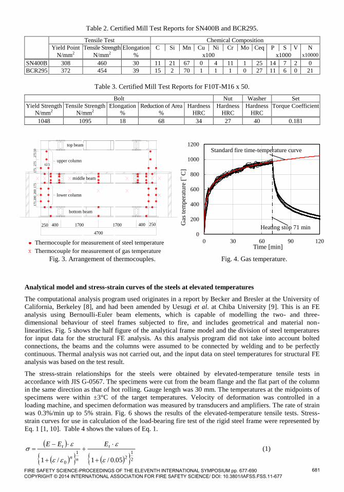
Table 2. Certified Mill Test Reports for SN400B and BCR295.
Tensile Test Chemical Composition
Yield Point Tensile Strength Elongation C Si Mn Cu Ni Cr Mo Ceq P S V N
N/mm2 N/mm2 % x100 x1000 x10000
SN400B 308 460 30 11 21 67 0 4 11 1 25 14 7 2 0
BCR295 372 454 39 15 2 70 1 1 1 0 27 11 6 0 21
Table 3. Certified Mill Test Reports for F10T-M16 x 50.
Bolt Nut Washer Set
Yield Strength Tensile Strength Elongation Reduction of Area Hardness Hardness Hardness Torque Coefficient
N/mm2 N/mm2 % % HRC HRC HRC
1048 1095 18 68 34 27 40 0.181
Thermocouple for measurement of steel temperature
x Thermocouple for measurement of gas temperature Fig. 3. Arrangement of thermocouples. Fig. 4. Gas temperature.
Analytical model and stress-strain curves of the steels at elevated temperatures
The computational analysis program used originates in a report by Becker and Bresler at the University of
California, Berkeley [8], and had been amended by Uesugi et al. at Chiba University [9]. This is an FE
analysis using Bernoulli-Euler beam elements, which is capable of modelling the two- and three-
dimensional behaviour of steel frames subjected to fire, and includes geometrical and material non-
linearities. Fig. 5 shows the half figure of the analytical frame model and the division of steel temperatures
for input data for the structural FE analysis. As this analysis program did not take into account bolted
connections, the beams and the columns were assumed to be connected by welding and to be perfectly
continuous. Thermal analysis was not carried out, and the input data on steel temperatures for structural FE
analysis was based on the test result.
The stress-strain relationships for the steels were obtained by elevated-temperature tensile tests in
accordance with JIS G-0567. The specimens were cut from the beam flange and the flat part of the column
in the same direction as that of hot rolling. Gauge length was 30 mm. The temperatures at the midpoints of
specimens were within ±3°C of the target temperatures. Velocity of deformation was controlled in a
loading machine, and specimen deformation was measured by transducers and amplifiers. The rate of strain
was 0.3%/min up to 5% strain. Fig. 6 shows the results of the elevated-temperature tensile tests. Stress-
strain curves for use in calculation of the load-bearing fire test of the rigid steel frame were represented by
Eq. 1 [1, 10]. Table 4 shows the values of Eq. 1.
2
12
1
0 05.0/1/1
t
nn
t EEE (1)
0
200
400
600
800
1000
1200
0 30 60 90 120
Gas
tem
per
atu
re [°C
]
Time [min]
Standard fire time-temperature curve
Heating stop 71 min
bottom beam
middle beam
top beam
upper column
lower column
17001700
50
275
275
175
175
200
200
175
62.5
4700
400 250400250
FIRE SAFETY SCIENCE-PROCEEDINGS OF THE ELEVENTH INTERNATIONAL SYMPOSIUM pp. 677-690 COPYRIGHT © 2014 INTERNATIONAL ASSOCIATION FOR FIRE SAFETY SCIENCE/ DOI: 10.3801/IAFSS.FSS.11-677
681

0
100
200
300
400
500
0 0.01 0.02 0.03 0.04 0.05
Str
ess
[N/m
m2]
Strain
23°C
300°C
400°C
500°C
600°C
700°C800°C
0
100
200
300
400
500
0 0.01 0.02 0.03 0.04 0.05
Str
ess
[N/m
m2]
Strain
300°C
20°C
400°C
500°C
700°C
600°C
800°C
Table 4. The values of Eq. 1.
Temperature
SN400B (Beam) BCR295 (Column)
E Et ε0 n E Et ε0 n
N/mm2 N/mm2 x10-6 N/mm2 N/mm2 x10-6
20°C 208000 3526 1300 2.0 208000 942.1 1900 2.0
300°C 193000 6076 1300 1.4 193000 2142.2 2200 1.4
400°C 191400 6343 1100 1.1 174000 -602.6 2400 1.1
500°C 155100 2869 1400 1.1 141000 -607.5 1800 1.1
600°C 134200 565 1000 1.1 122000 -262.4 1000 1.1
700°C 110000 -98 500 1.1 100000 -96.3 600 1.1
800°C 85800 39 400 1.1 78000 72.2 400 1.1
(a) Division of temperatures for the beam elements (b) Division of temperatures in the beam element
Fig. 5. Half figure of the analytical frame model and the division of steel temperatures.
(a) SN400B (Beam) (b) BCR295 (Column)
Fig. 6. Stress-strain relationships for the steels at elevated temperatures.
mid-span of
middle beam
mid-span
top beam (ambient temperature)
bottom beam
(ambient temperature)
upper column (ambient temperature)
beam-splice connection beam end
mid-span
panel zone
top end of lower column
bottom end
mid-span
47
47
47
300
1509
9
47
47
47
Ttf (top flange)
Tbf (bottom flange)
Tuw (upper web)
Tlw (lower web)
2/uwtf TT
3/2 lwuw TT
3/2 lwuw TT
2/lwbf TT
Solid lines : Tests
Broken lines: Eq. 1
Solid lines : Tests
Broken lines: Eq. 1
FIRE SAFETY SCIENCE-PROCEEDINGS OF THE ELEVENTH INTERNATIONAL SYMPOSIUM pp. 677-690 COPYRIGHT © 2014 INTERNATIONAL ASSOCIATION FOR FIRE SAFETY SCIENCE/ DOI: 10.3801/IAFSS.FSS.11-677
682

As shown in Fig. 6, the calculation models of the stress-strain curve roughly agreed with the elevated
tensile test results. The relative thermal elongation of carbon steel for use in the FE analysis is given by
Eurocode 3 equations [11].
RESULTS AND DISCUSSION
Temperature distribution in the steel frame
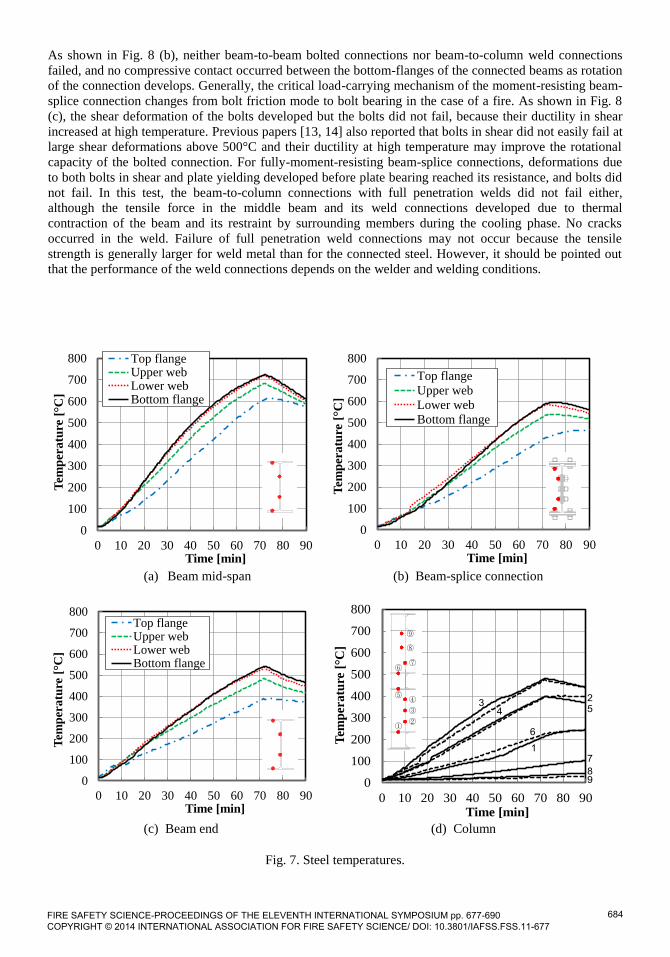
Fig. 7 (a), (b), and (c) show the temperatures at the mid-span, the beam-splice connection (north side), and
the end (north side) of the middle beam, respectively. The temperatures of the north side at the connection
and the end of the beam were almost same as that of the south side. Heating was stopped at 71 min after
ignition, when the beam mid-span deflection reached 100 mm. As shown in Fig. 7(a), the temperatures at
the bottom flange and the web lower part of the beam mid-span were almost the same and rose to about
580°C at 50 min and above 700°C after 70 min. The rising rate of steel temperature decreased from 600°C,
because specific heat capacity of steel gradually increased from 600°C. The temperature was lower for the
top flange than for the bottom flange, because the boundary conditions of heat transfer differed. As shown
in Fig. 7(b), the temperature was distinctly lower for the beam-splice connection than for the mid-span of
the beam, because moment-resisting beam-splice connections had a relatively high heat capacity. The mean
temperature of the connections (377°C at 50 min and 510°C at 67.5 min) was 71-77 % that for the beam
mid-span (528°C at 50 min and 659°C at 67.5 min). The time to reach the limiting rate of deflection for
flexural elements in accordance with ISO834-1 was 67.5 min. This result was similar to previous report
[12] of load-bearing fire tests, imitating the action of continuous beams with beam splice connections. As
shown in Fig. 7 (c), the temperature was also lower for the end of the beam than for the mid-span of the
beam, because the heat conduction from the beam end to the panel-zone and the unheated upper column
occurred at the end due to difference of the temperatures. The temperatures at the end and mid-span of the
beam were similar up to 100°C at 10 min after ignition, and subsequently the difference between the two
temperatures gradually increased. The mean temperature of the ends (368°C at 50 min and 471°C at 67.5
min) was about 70 % that for the mid-span. The differences of steel temperatures between the mid-span, the
ends of the beam, and the beam-splice connections were considerable. In order to approximate the critical
temperature of the beam accurately, the temperature reduction factors should be considered. The
temperature reduction factors are shown in Table 5 in the section "Critical temperature of the beam".
Fig. 7 (d) shows the temperatures of the columns and the panel zone (north side). Although the fire
protection of the lower column is the same as that for the middle beam, as shown in Fig. 7 (a) and (d), the
steel temperature was distinctly lower for the mid-span of the lower column than for the mid-span of the
middle beam, and the difference of mean temperatures was above 150°C after 50 min. The section factor,
which is the ratio of the heated surface area of a steel member to the volume of the member, was lower for
the SHS column (0.091 mm-1
) than for the I-beam (0.191 mm-1
). The temperatures of the lower column
were below 500°C and the temperature at the bottom of the upper column was about 80°C at 70 min. The
temperatures at the section where strain gages were installed were below 40°C up to 70 min. The
temperature was lower for the upper diaphragm (220°C at 70 min) than for the lower diaphragm (390°C at
70 min) of the panel zone.
Observations, connections behaviour, and failure mode
Fig. 8 (a) shows the global aspect of residual deformation of the frame after the test. The middle beam
deflected to a great extent, due to rotation at the connections, shear deformation at the insides of the
connections, and bending deflection at the mid-span of the beam. Failure of the beam occurred due to the
shear force; i.e., diagonal tension in the beam web adjacent to the connection, and thus a “truss analogy” as
a mechanism of shear transfer. Therefore, the resistance of the beam should be related not only to bending
resistance but also to shear resistance. For the rigid steel frame, the shear failure of beams may occur in
case of a fire, because the shear arm ratio (the ratio of shear span to depth) is smaller for a continuous beam
than for a simply supported beam with pin connections (e.g., fin plate connection). Meanwhile, the bending
failure mode, which is a plastic collapse of the beam and its connections due to the bending moment,
should be also considered, because rotation of the connections was very large. Members other than the
middle beam were not deformed to a great extent after the test.
FIRE SAFETY SCIENCE-PROCEEDINGS OF THE ELEVENTH INTERNATIONAL SYMPOSIUM pp. 677-690 COPYRIGHT © 2014 INTERNATIONAL ASSOCIATION FOR FIRE SAFETY SCIENCE/ DOI: 10.3801/IAFSS.FSS.11-677
683
0
100
200
300
400
500
600
700
800
0 10 20 30 40 50 60 70 80 90
Tem
per
atu
re [ C
]
Time [min]
Top flangeUpper webLower webBottom flange
0
100
200
300
400
500
600
700
800
0 10 20 30 40 50 60 70 80 90
Tem
per
atu
re [ C
]
Time [min]
Top flange
Upper web
Lower web
Bottom flange
0
100
200
300
400
500
600
700
800
0 10 20 30 40 50 60 70 80 90
Tem
per
atu
re [ C
]
Time [min]
Top flangeUpper webLower webBottom flange
As shown in Fig. 8 (b), neither beam-to-beam bolted connections nor beam-to-column weld connections
failed, and no compressive contact occurred between the bottom-flanges of the connected beams as rotation
of the connection develops. Generally, the critical load-carrying mechanism of the moment-resisting beam-
splice connection changes from bolt friction mode to bolt bearing in the case of a fire. As shown in Fig. 8
(c), the shear deformation of the bolts developed but the bolts did not fail, because their ductility in shear
increased at high temperature. Previous papers [13, 14] also reported that bolts in shear did not easily fail at
large shear deformations above 500°C and their ductility at high temperature may improve the rotational
capacity of the bolted connection. For fully-moment-resisting beam-splice connections, deformations due
to both bolts in shear and plate yielding developed before plate bearing reached its resistance, and bolts did
not fail. In this test, the beam-to-column connections with full penetration welds did not fail either,
although the tensile force in the middle beam and its weld connections developed due to thermal
contraction of the beam and its restraint by surrounding members during the cooling phase. No cracks
occurred in the weld. Failure of full penetration weld connections may not occur because the tensile
strength is generally larger for weld metal than for the connected steel. However, it should be pointed out
that the performance of the weld connections depends on the welder and welding conditions.
(a) Beam mid-span (b) Beam-splice connection
(c) Beam end (d) Column
Fig. 7. Steel temperatures.
0
100
200
300
400
500
600
700
800
0 10 20 30 40 50 60 70 80 90
Tem
per
atu
re [ C
]
Time [min]
1
43
25
6
7
89
①②
③
④⑤
⑥⑦
⑧
⑨
FIRE SAFETY SCIENCE-PROCEEDINGS OF THE ELEVENTH INTERNATIONAL SYMPOSIUM pp. 677-690 COPYRIGHT © 2014 INTERNATIONAL ASSOCIATION FOR FIRE SAFETY SCIENCE/ DOI: 10.3801/IAFSS.FSS.11-677
684

(a) Global aspect of the frame
(b) Connections (c) Bottom flange bolts
Fig. 8. Residual deformation of the frame after the test.
Beam deflection, beam elongation, and thermal stress
Fig. 9 (a) and (b) show the deflection and the rate of deflection (per min) at the mid-span of the middle
beam and a comparison of the test result with the result calculated from FE analysis (legend “FEA”) using
Bernoulli-Euler beam elements. The deflection was the relative vertical displacements between mid-span
and ends of the beam. In Fig. 9 (a), the initial deflection is zero, and this does not include deflection due to
variation of loading at ambient temperature before heating. The recorded beam mid-span deflection at the
target load of 73.8 kN was about 5 mm. During the early stages of the fire, up to 30 min, the beam
deflection was very low, because the thermal expansion across the height of the beam, which would
normally cause much of the deflection of the beam, was countered by the restraint to rotation at its ends,
which applied a hogging moment. Small increases of the deflection occurred suddenly at 33 min and 44
min due to the occurrence of slip between the splices and the connected beams, and the rate of deflection
gradually increased after 50 min. The fire resistance time was 67.5 min (when the mean temperature at the
mid-span of beam was 659°C), which was the time to reach the limiting rate of deflection (L2/9000d=7.3
mm/min, L=4450 mm: the span of the test specimen, d=300 mm: the beam depth) for flexural elements in
accordance with ISO834-1. For estimation of the limiting deflection and the limiting rate of deflection, the
FIRE SAFETY SCIENCE-PROCEEDINGS OF THE ELEVENTH INTERNATIONAL SYMPOSIUM pp. 677-690 COPYRIGHT © 2014 INTERNATIONAL ASSOCIATION FOR FIRE SAFETY SCIENCE/ DOI: 10.3801/IAFSS.FSS.11-677
685

0
20
40
60
80
100
120
0 10 20 30 40 50 60 70 80
Def
len
ctio
n [
mm
]
Time [min]
Test result
FEA result
0.0
2.5
5.0
7.5
10.0
12.5
15.0
0 10 20 30 40 50 60 70 80
Ra
te o
f d
efle
nct
ion
[m
m/m
in]
Time [min]
Test result
FEA result
span of the test specimen L was taken to be the length of the beam, which was defined as the distance
between the centroids of the columns. It should be pointed out that the limiting values for fire resistant time
might be not completely correct, because this was not a test for a simply supported beam. Heating was
stopped at 71 min, when the beam mid-span deflection reached 100 mm, and loading was stopped at 73
min (when the mean temperature at mid-span of the beam was 682°C), because the rate of deflection
reached 15 mm/min and the security of the testing facility was of concern. The specimen might lose its
load-bearing capacity around 73 min, although the loading could not be kept up to that point, when the
beam exhibited sufficient catenary action. The FE analysis did not take into account the beam-to-beam
bolted connection, but the result from FEA agreed with the test result up to about 65 min. This time was
close to the fire resistance time (67.5 min) in accordance with ISO834-1. Subsequently, the rate of
deflection was lower for the FEA result than for the test result, because the FE analysis using Bernoulli-
Euler beam elements did not take into account the development of beam deflection due to shear failure. The
prediction may need a full non-linear FE analysis using shell elements.
Fig. 10 shows the elongation of the middle beam, which was measured by displacement transducers placed
horizontally at the bottom of the upper columns (see Fig. 1). The elongation was thermal elongation of the
beam receiving axial restraint by the surrounding members. During the early stages of the fire, up to 50 min
(when the mean temperature at the mid-span of beam is 528°C), the elongation of the beam increased in
proportion to the heating time or the temperature of the beam, but the value was considerably lower than
the free thermal elongation of the beam. Then the elongation decreased due to the development of
deflection of the beam. Fig. 10 also shows the sudden low decreases of the elongation due to the occurrence
of slip between the splices and the connected beams, but the elongation might be not affected by the bolted
connections very much. The FEA result approximated the whole aspect of the test result for the elongation,
but it seemed that slip of the bolted connection was one reason for the difference between the test result and
FEA result. It should be pointed out that the FEA result for the elongation did not agree with the test result
after 65 min, as in the case of beam deflection.
Fig. 11 shows the variation of the shear force in the upper columns. The shear force in the test was
calculated from the values of the strain gages installed at the two sections of the upper column. This was
due to thermal elongation of the middle beam and its restraint from the columns. Therefore, Fig. 11 for the
variation of the shear force was similar to Fig. 10 for the elongation of the middle beam. The shear force in
the upper columns increased during the early stages of the fire, up to 45 min in the test. After the bending
moment at the ends of the column reached the resistance of the column, the shear force in the column
decreased due to a reduction of the steel‟s resistance. Moreover, the shear force decreased sharply due to
development of beam deflection after 50 min. The shear force on columns became zero at 72 min, when the
beam reached the limit state stage due to its shear or bending ultimate strength at elevated temperature, and
then the tensile force in the beam increased and the beam might exhibit catenary action. The FEA result
approximated the whole aspect of the test result for the shear force in the columns, as in the case of
elongation of the middle beam.
(a) Deflection (b) Rate of the deflection
Fig. 9. Deflection at the mid-span of the middle beam. FIRE SAFETY SCIENCE-PROCEEDINGS OF THE ELEVENTH INTERNATIONAL SYMPOSIUM pp. 677-690 COPYRIGHT © 2014 INTERNATIONAL ASSOCIATION FOR FIRE SAFETY SCIENCE/ DOI: 10.3801/IAFSS.FSS.11-677
686

0
2
4
6
8
10
12
14
0 10 20 30 40 50 60 70 80
Elo
ng
ati
on
[m
m]
Time [min]
Test result
FEA result
-50
0
50
100
150
200
250
0 10 20 30 40 50 60 70 80
Sh
ear
forc
e[k
N]
Time [min]
Test result
FEA result
Fig. 10. Elongation of middle beam. Fig. 11. Shear force in upper columns.
Critical temperature of the beam
The critical temperatures for continuous steel beams can be approximated on the basis of the theory of
simple plastic design [1, 11]. An approximation to the critical temperature of a simple plastic collapse
model was given by AIJ recommendation [1]. This paper also discusses the approximation method for the
critical temperature of steel beams with moment-resisting beam-splice connections. The simple plastic
collapse model originated in Ozaki-Suzuki„s concept [15], which was based on the resistance of the beam
and the beam-splice connection in the fire limit state calculated as for an undivided span with three plastic
hinges. The resistance of the beam-splice connection was on the bolt failure and was calculated from the
strength of the bolts. In this study, the differences of steel temperatures between the mid-span, the ends of
the beam, and the beam-splice connections were also taken into consideration [12]. In order to take into
account the considerable difference of their temperatures, the critical temperature was defined by the mean
temperature of the section at the mid-span of the beam at the fire resistance time or at the limit state stage.
Table 5 shows the temperature reduction factors for the beam end, the beam-splice connection, and the
beam web, which were the mean temperatures of the sections or the web parts divided by the mean
temperature of the section at the mid-span of the beam at 67.5 min, which was the fire resistance time from
the test result. The critical temperature of the beam Tcr was given by Eq. 2 and this was the minimum
critical temperature calculated by Eq. 3 – Eq. 6. Table 5 also shows the design resistance for the beam and
the connection at ambient temperature for calculation of the critical temperature.
4321 ,,,min crcrcrcrcr TTTTT (2)
111 crecrp TTMlP (3)
222 crjbbujcrp TMTMlP (4)
3crwy TQP (5)
4crwbbbuj TQP (6)
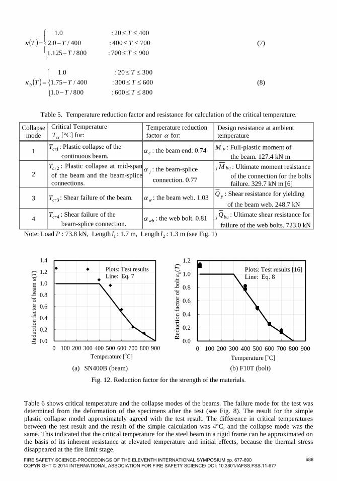
On the basis of elevated-temperature tensile tests, the reduction factor for the effective yield strength of the
steel used for the beam at elevated temperature was given by Eq. 7. As shown in Fig. 12 (a), the reduction
factor for the approximation of the critical temperature agreed with the 1% proof stress from the tensile
tests result. The strength reduction factor of the bolts at elevated temperature was given by Eq. 8 from the
results of our previous study [16] on HSFG bolts as shown in Fig. 12 (b).
FIRE SAFETY SCIENCE-PROCEEDINGS OF THE ELEVENTH INTERNATIONAL SYMPOSIUM pp. 677-690 COPYRIGHT © 2014 INTERNATIONAL ASSOCIATION FOR FIRE SAFETY SCIENCE/ DOI: 10.3801/IAFSS.FSS.11-677
687
0.0
0.2
0.4
0.6
0.8
1.0
1.2
0 100 200 300 400 500 600 700 800 900
Red
uct
ion
fac
tor
of
bolt
κb(T
)
Temperature [°C]
Plots: Test results [16]
Line: Eq. 8
0.0
0.2
0.4
0.6
0.8
1.0
1.2
1.4
0 100 200 300 400 500 600 700 800 900
Red
uct
ion f
acto
r of
bea
m κ
(T)
Temperature [°C]
Plots: Test results
Line: Eq. 7
900700:800/125.1
700400:400/0.2
40020:0.1
TT
TT
T
T
(7)
800600:800/0.1
600300:400/75.1
30020:0.1
TT
TT
T
Tb
(8)
Table 5. Temperature reduction factor and resistance for calculation of the critical temperature.
Collapse
mode
Critical Temperature
crT [°C] for: Temperature reduction
factor for: Design resistance at ambient
temperature
1 1crT : Plastic collapse of the
continuous beam. e : the beam end. 0.74 pM : Full-plastic moment of
the beam. 127.4 kN m
2 2crT : Plastic collapse at mid-span
of the beam and the beam-splice
connections.
j : the beam-splice
connection. 0.77
buj M : Ultimate moment resistance
of the connection for the bolts
failure. 329.7 kN m [6]
3 3crT : Shear failure of the beam. w : the beam web. 1.03 yQ : Shear resistance for yielding
of the beam web. 248.7 kN
4 4crT : Shear failure of the
beam-splice connection. wb : the web bolt. 0.81 buj Q : Ultimate shear resistance for
failure of the web bolts. 723.0 kN
Note: Load P : 73.8 kN, Length 1l : 1.7 m, Length 2l : 1.3 m (see Fig. 1)
(a) SN400B (beam) (b) F10T (bolt)
Fig. 12. Reduction factor for the strength of the materials.
Table 6 shows critical temperature and the collapse modes of the beams. The failure mode for the test was
determined from the deformation of the specimens after the test (see Fig. 8). The result for the simple
plastic collapse model approximately agreed with the test result. The difference in critical temperatures
between the test result and the result of the simple calculation was 4°C, and the collapse mode was the
same. This indicated that the critical temperature for the steel beam in a rigid frame can be approximated on
the basis of its inherent resistance at elevated temperature and initial effects, because the thermal stress
disappeared at the fire limit stage.
FIRE SAFETY SCIENCE-PROCEEDINGS OF THE ELEVENTH INTERNATIONAL SYMPOSIUM pp. 677-690 COPYRIGHT © 2014 INTERNATIONAL ASSOCIATION FOR FIRE SAFETY SCIENCE/ DOI: 10.3801/IAFSS.FSS.11-677
688

Table 6. The critical temperature of the beam with the beam-splice connections.
Test result Calculation result crT 1crT 2crT 3crT 4crT
Shear failure
of the beam
Shear failure
of the beam 3crT
Bending failure of: Shear failure of:
beam beam and connections beam connection
659 °C 663 °C 695 °C 688 °C 663 °C 813 °C
Notice: These temperatures were the mean temperatures of the section at the mid-span of the beam.
CONCLUSIONS
This paper has presented structural behaviour results of a load-bearing fire test on a rigid steel frame with
connections. This fire test was intended to provide experimental data to help understand the fundamental
structural responses of rigid steel frames in fire. The main conclusions were:
(1) Temperature distribution: The difference of steel temperatures between the centre, the ends of the
beam, and the beam-splice connections was considerable. The mean temperature of the beam-splice
connections was 71-77% of that of the beam mid-span. The mean temperature of the ends was about
70% that of the mid-span.
(2) Neither the full-moment-resisting beam-splice connection nor the full penetration weld connection
failed, although a large beam mid-span deflection developed during the heating phase and the tensile
force in the heated beam developed due to thermal contraction of the beam and its restraint from the
surrounding members during the cooling phase.
(3) The beam deflection was very low during the early stages of the fire, because the thermal expansion
across the height of the beam was countered by the restraint to rotation at its ends, which applied a
hogging moment. The beam deflection gradually increased above 500°C, and ultimately shear failure
of the beam occurred. Therefore, the resistance of the beam should be related not only to bending
resistance but also to shear resistance. For the rigid steel frame, the shear failure of beams may occur in
the case of a fire, because the shear arm ratio is shorter for a continuous beam than for a simply
supported beam with pin connections.
(4) The shear force in the columns increased during the early stages of fire due to thermal elongation of
the heated beam and its restraint by the columns. Then the shear force decreased due to degradation of
the column and the development of beam deflection, and ultimately, it became zero when the beam
reached the limit state stage due to its shear or bending ultimate strength at elevated temperature.
(5) The difference in critical temperatures between the test result and the result of the simple calculation
was 4°C, and the collapse mode was the same. The critical temperature for the steel beam in a rigid
frame was approximated on the basis of its inherent resistance at elevated temperature and initial
effects, because the thermal stress disappeared at the fire limit stage.
(6) The influence of the slip of the beam-splice connection on the behaviour of the frame in fire was not
very large. The result of a finite element analysis using Bernoulli-Euler beam elements approximately
agreed with the test result before the occurrence of shear failure of the beam.
AKNOWLEDGEMENTS
This work was supported by JSPS KAKENHI Grant Number 23246101. The authors would like to thank
Prof. Minehiro Nishiyama and Prof. Kazunori Harada at Kyoto University for giving us advice in the
meeting of JSPS KAKENHI. The authors would like to acknowledge Toa-rika Co., Ltd for producing the
specimen.
FIRE SAFETY SCIENCE-PROCEEDINGS OF THE ELEVENTH INTERNATIONAL SYMPOSIUM pp. 677-690 COPYRIGHT © 2014 INTERNATIONAL ASSOCIATION FOR FIRE SAFETY SCIENCE/ DOI: 10.3801/IAFSS.FSS.11-677
689

REFERENCES
[1] Architectural Institute of Japan, “Recommendation for fire resistant design of steel structures”, 1st
edition 1999, 2nd edition 2008. (in Japanese)
[2] Liu, T.C.H., Fahad, M.K., and Davies, J.M., Experimental investigation of behaviour of axially
restrained steel beams in fire, Journal of Constructional Steel Research 58, 2002, pp. 1211–1230,
http://dx.doi.org/10.1016/S0143-974X(01)00062-1
[3] Wald, F., Simoes da Silva, L., Moore, D., Lennon, T., Chladna, M., Santiago, A., Benes, M., and
Borges, L., Experimental behaviour of a steel structure under natural fire, Fire Safety Journal 41,
2006, pp. 509-522, http://dx.doi.org/10.1016/j.firesaf.2006.05.006
[4] Santiago A, Simoes da Silva L., Vaz, G., Vila Real P., and Gameiro, L.A., Experimental
investigation of the behaviour of a steel sub-frame under a natural fire, Steel and Composite
Structures, Vol. 8, No. 3, 2008, pp. 243-264
[5] Wang, Y.C., Dai, X.H., and Bailey, C.G, An experimental study of relative structural fire behaviour
and robustness of different types of steel joint in restrained steel frames, Journal of Constructional
Steel Research 67, 2011, pp. 1149-1163, http://dx.doi.org/10.1016/j.jcsr.2011.02.008
[6] Architectural Institute of Japan, Recommendation for design of connections in steel structures,
2001. (in Japanese)
[7] Lim, S., Ota, S., Sakaguchi, A., Tanaka, Y., Tasaka, S., Tani, M., Harada, K., and Nishiyama, M.,
Experimental study on fire-resistance of reinforced concrete frames with column-beam connection,
Part 1: Outline, Summaries of Technical Papers of Annual Meeting, Architectural Institute of
Japan, A-2, 2011, pp. 21-22
[8] Becker, J., Bresler, B., FIRES-RC--- A Computer Program for the Fire Response of Structure ---
Reinforced Concrete Frames, Report No.UCB FRG74-3, University of California Berkeley, 1974
[9] Li, Y., Lin, H., Hirashima, T., Uesugi, H., and Wakamatsu, T., An analytical method of deflection
behavior concerning three-dimensional steel frame exposed to fire which takes account of the
thermal expansion of a floor slab, International Journal for Fire Science and Technology, Vol. 24,
No. 4, Center for Fire Science and Technology, Tokyo University of Science, 2005, pp. 211-236
[10] Richard, R.M and Abbott, B.J., Versatile Elastic-Plastic Stress-Strain Formula, EM4 Technical
Note, 1975, pp. 511-515
[11] CEN, EN 1993-1-2. Eurocode 3: Design of steel structures Part 1-2: General rules - Structural fire
design, British standards Institution, 2005
[12] Hirashima, T., Toyoda, K., Yatagai, A., Esaki, Y., Tasaka, S., Yoshida, M., Masuda, H. and
Harada, K., Experimental Study on Fire Resistance of H-shaped Steel Beams with High Strength
Bolted Joints, J. Struct. Constr. Eng., AIJ, Vol.75 No.658, 2010, pp. 2257-2265 (in Japanese),
http://dx.doi.org/10.3130/aijs.75.2257
[13] Hirashima T. and Uesugi H., “Experimental Study on Shear Strength of Friction-Type High-
Tension Bolted Joints at Elevated Temperature”, Proceedings of the 6th Asia-Oceania Symposium
on Fire Science and Technology, Daegu, Korea, 272-284, 2004.
[14] Hongxia Y., Burgess I.W., Davison J.B. and Plank R.J, “Experimental investigation of the
behaviour of fin plate connections in fire”, Proceedings of ICSCS 2007, 541-548, 2007.
[15] Ozaki, F. and Suzuki, H., Ultimate temperatures of steel frames with high strength bolted beam
joints subjected to fire, J. Struct. Constr. Eng., AIJ, No.547, 2001, pp. 207-214 (in Japanese)
[16] Hirashima, T., Hamada, N., Ozaki, F., Ave, T. and Uesugi, H., Experimental Study on Shear
Deformation behavior of High Strength Bolts at Elevated Temperature, J. Struct. Constr. Eng.,
AIJ, No.621, 2007, pp.175-180 (in Japanese)
FIRE SAFETY SCIENCE-PROCEEDINGS OF THE ELEVENTH INTERNATIONAL SYMPOSIUM pp. 677-690 COPYRIGHT © 2014 INTERNATIONAL ASSOCIATION FOR FIRE SAFETY SCIENCE/ DOI: 10.3801/IAFSS.FSS.11-677
690