an end-to-end system for designing mechanical structures...
TRANSCRIPT

An End-to-End System for Designing Mechanical Structures for
Print-and-fold Robots
Ankur M. Mehta and Daniela Rus1
Abstract— This work presents a script-based develop-ment environment aimed at allowing users to easily designand create mechanical bodies for folded plastic robots.The origami-inspired fabrication process is inexpensiveand widely accessible, and the tools developed in thiswork allow for open source design sharing and modularreuse. Designs are generated by recursively combiningmechanical components – from primitive building blocks,through mechanisms and assemblies, to full robots – in aflexible yet well-defined manner. This process was usedto design robotic elements of increasing complexity upto a multi-degree-of-freedom compliant manipulator arm,demonstrating the power of this system. The developedsystem is extensible, opening avenues for further researchultimately leading to the development of a complete robotcompiler.
I. INTRODUCTION
Robots can come in a variety of form factors witha number of uses, displaying potential to become in-dispensable for purposes such as academic research,educational outreach, or general household use [1]–[3]. However, the power of robotics comes from cus-tomizability in the system design. To enable the generalpublic to personally design and create individualizedrobots, non-specialized users must be able to go fromproblem specification to device fabrication rapidly andrepeatedly.
Though there are many computer aided design(CAD) packages focusing on various stages of thisprocess, the creation of a robotic system still requiresa multitude of such tools, along with the specializedskills needed to navigate each one. This currentlyleaves robotics within a domain of experts. To bringpersonalized robots into the homes of the general pub-lic, the complete design process needs to be reworked.
This paper presents a toolbox-like system to simplifyand streamline the design and manufacture of printablerobot bodies. Mechanical structures are fabricated in anorigami-inspired process wherein precision patternedand cut 2D sheets of plastic are folded into 3D ele-ments. Designs for these structures are generated bya collection of Python scripts which allow a user todefine complex geometries by hierarchically composingsimpler building blocks, starting from a library of basicprimitives. These designs are then fabricated using an
*This work was supported by the National Science Foundation,grant numbers 1240383 and 1138967.
1A. Mehta and D. Rus are with the Computer Science and ArtificialIntelligence Laboratory, Massachusetts Institute of Technology, Cam-bridge, MA 02139, USA. email: {mehtank, rus}@csail.mit.edu
inexpensive desktop paper/vinyl cutter. The resultingprocess is intuitive, versatile, and extensible, allowingquick and easy design of sophisticated robot bodies. Ituses cheap and easily available software and hardwaretools and raw materials, making it accessible to a casualhobbyist.
The contributions presented in this paper include:
• a method of abstracting 2D fold patterns viascripted objects,
• a composition paradigm to generate hierarchicalprint-and-fold mechanical designs,
• a collection of mechanical elements forming a li-brary of building blocks, and
• complex multi-degree-of-freedom robot bodies de-signed using the aforementioned system.
II. ORIGAMI INSPIRED FOLDING
There are many tools and processes available tobe used in the fabrication of mechanical structures,optimized for a variety of applications. When con-sidering the task of creating custom designed robotbodies, several concerns take precedence. The designof mechanical structures often involves trial-and-erroror successive refinement. In order to facilitate sucha process, the fabrication method must be relativelyfast and cheap, while still versatile enough to producethe variety of structures necessary for arbitrary robotbodies.
A common rapid prototyping method is 3D printing,made accessible to home users by products such asthe MakerBot [4] and popularized through user com-munities like Thingiverse [5]. Structures are designedby creating 3D solid models, which are then fabricatedthrough an additive manufacturing process using plas-tic stock material. Current 3D printers can make a widevariety of solid body rigid objects, but are significantlylimited in permitting structures with mechanical de-grees of freedom. Furthermore, the additive process canoften take hours to build a complete model.
Instead, this work focuses primarily on an origami-inspired print-and-fold process for creating 3D struc-tures from 2D patterned sheets of plastic, as presentedin e.g. [6], [7]. Such patterns can be quickly printedusing an inexpensive desktop paper/vinyl cutter, withraw material cheaply and readily available. This pro-cess inherently allows for constrained motion by usingpatterned folds as hinges. Similar to the diversity dis-played by origami creations, the print-and-fold process
allows for a wide range of mechanical designs. Thisprocess has already been used to manually design anumber of successful standalone robots [6]–[9].
III. DESIGN PRINCIPLES
To enable personal robotics to gain widespread trac-tion, the process by which desired devices are designedmust be greatly simplified. With a potential targetaudience of school children or the general public, thesystem must be usable by those without a backgroundin engineering design. In particular, there are a numberof guiding principles to help translate users’ visionsinto mechanical structures as easily and directly aspossible.
Most importantly, the system environment should beintuitive, allowing an inexperienced user to easily un-derstand and implement the design process. A “whatyou see is what you get” (WYSIWYG) model is ideal,wherein the starting state and all operations directlycorrelate to their real-world implementation. Generateddesigns should be easy to share, modify, adapt, andextend. Free and open source tools are preferable toexpensive and esoteric computer aided design (CAD)programs, and designs should be similarly unencum-bered by proprietary standards.
Earlier work on origami inspired robotics [6]–[8], [10]were lacking in one or more of those goals. Designsare often manually drawn from scratch in sophisticated2D CAD programs, and can be difficult to visualize as3D objects. Most robots are created as monolithic inte-grated designs, and so these issues are compounded asdesigns grow in size and complexity.
The design package presented in this paper consistsof a collection of Python scripts that automate theend-to-end process of designing and fabricating themechanical body of a folded plastic robot. The sim-ple text-based representation of these designs enablesmany of the same benefits of the Open Source Softwaremovement such as incremental modification, modularreuse, and community based sharing of designs. Expertusers can generate new modules and edit the scriptsdirectly, while novice users need only be concernedwith designed modules as building blocks, connectingthem through a simple interface that hides the detailsof the underlying software.
IV. DESIGN ENVIRONMENT IMPLEMENTATION
The system presented in this paper is outlined infigure 1.
A. Software abstraction
3D folded plastic geometries are defined by their foldpatterns – the 2D drawings specifying edges to eithercut or fold. However, because of the non-intuitivemapping between the fold pattern and its resulting 3Dgeometry, mechanical elements are first abstracted intotheir constituent components, hiding the underlying
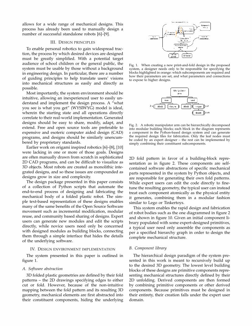
Fig. 1. When creating a new print-and-fold design in the proposedsystem, a designer needs only to be responsible for specifying theblocks highlighted in orange: which subcomponents are required andhow their parameters are set, and what parameters and connectionsto expose to higher designs.
Fig. 2. A robotic manipulator arm can be hierarchically decomposedinto modular building blocks; each block in the diagram representsa component in the Python-based design system and can generatethe required design files for fabrication. Only the leaf nodes mustbe coded by an expert designer – the rest can be implemented bysimply combining their constituent subcomponents.
2D fold pattern in favor of a building-block repre-sentation as in figure 2. These components are self-contained software abstractions of specific mechanicalparts represented in the system by Python objects, andare responsible for generating their own fold patterns.While expert users can edit the code directly to fine-tune the resulting geometry, the typical user can insteadtreat each component atomically as the physical entityit generates, combining them in a modular fashionsimilar to Lego or Tinkertoys.
This system enables the rapid design and fabricationof robot bodies such as the one diagrammed in figure 2and shown in figure 10. Given an initial component li-brary populated with some expert-designed primitives,a typical user need only assemble the components asper a specified hierarchy graph in order to design thecomplete mechanical structure.
B. Component library
The hierarchical design paradigm of the system pre-sented in this work is meant to recursively build upto the desired 3D geometry. The lowest level buildingblocks of these designs are primitive components repre-senting mechanical structures directly defined by their2D unfolding. Derived components are then formedby combining primitive components or other derivedcomponents. Because primitives must be designed intheir entirety, their creation falls under the expert userdomain.

Each component implements a common set of meth-ods defined in the parent class, providing a structuredimplementation for parametrization and composition.These methods can then be called from the casualuser domain to enable customization and extensibilitywithin the expert-defined bounds. The parameters ofa component are defined by the expert designer toenumerate user-configurable degrees of freedom inthe geometric specification of a design, an exampleof which is shown in lines 6-10 of listing 2. Typicalparameters include size, shape, or repetition counts.The component designer is responsible for ensuringthat the assigned parameter values are then reflectedin the final design of the component. Each componentalso specifies a list of connections – locations identifiedby the designer to which other components can safelybe attached. This can be seen in lines 12-15 of listing 2.
C. Composition
A design implemented in this system is a constrainedcombination of components (and is itself another com-ponent); specifying a design in this system consists ofrecursively composing the right collection of compo-nents to generate the desired robot body. Composinga new design requires the user to follow a prescribedset of steps to generate the Python class representingthe new component. These steps could be carried outby manually generating the required Python script, oran automated user interface could generate the codedirectly from user input.
The required subcomponents must first be identifiedand collected, as in line 4 of listing 2. If any do notyet exist in the library, they must be created either bydrawing a new primitive component or by composinga new derived component in the same manner beingpresented here.
By default, the parameter set of the new derivedcomponent begins as simply a union of the parametersof all its subcomponents. However, an assembled de-sign often imposes constraints between related param-eters of its constituent parts, and so these constraintsmust be specified relative to the desired parameters ofthe assembly. The final set of parameters must exactlycover the available geometric degrees of freedom ofthe composite design, and specify all the parametersof the subcomponents. The parameters in listing 2 aredeclared in lines 6-10, and set in lines 17-20.
Finally, the subcomponents must be attached to eachother along allowable connections to generate the finalgeometry, as accomplished by lines 22-40 of listing 2.As each subcomponent is actualized as a 2D unfoldingof the desired 3D structure, attaching two unfoldingsmust result in a new planar unfolding of the compositestructure. With careful design, this can sometimes beachieved by simply concatenating the two unfoldingsalong a shared edge. Other times, however, a more
rigorous algorithm such as that presented in [11] mustbe used to generate the composition.
D. Fabrication
Each component in this system is an instance of acommon parent class, stored as an executable Pythonscript. When run, this class calls a method to generatethe final 2D design file to be sent directly to the cuttingmachine, thus providing the fabrication path for theprintable robot. The class also has methods to gener-ate 3D representations to aid in the design process,demonstrating the static and dynamic appearance andbehavior of the resulting structure. Instantiating thefinal design consists of setting the required parameters,generating a 2D design file, sending it to a cutter topattern a sheet of plastic, then folding it to the final 3Dgeometry, using generated models for guidance.
V. RESULTS
The proposed system was used to design and fabri-cate a number of mechanical structures.
A. Primitive components
There are many possible primitives, a subset ofwhich are presented below. They are typically limitedto simple structures; more complex structures can of-ten be subdivided into compositions of these simplerdesigns.
1) Basic shapes: The simplest non-trivial geometriesrequired to build 3D structures are convex polyhedra.Building blocks such as cubes (shown in figure 3,from the code in listing 1) and beams (shown infigure 4) form the structural elements of most foldedplastic robots. The unfolded geometries are specifiedby Python scripts as first presented in [9]: and encap-sulated in the component framework presented above.They are parametrized to allow for user specified ge-ometries. For example, the length, diameter, numberof sides, and face angles can all be adjusted for abeam component. The components also publish theiravailable connections – edges along which other com-ponents are allowed to connect.
1 class Cube(Drawing):
2 def __init__(self, edge, top=True, bot=True):
3 Drawing.__init__(self)
45 r = Rectangle(edge, edge)
6 self.append(r, 'rm')
7 if top:
8 self.attach('rm.e0', r, 'e2', 'rt', 90)
9 if bot:
10 self.attach('rm.e2', r, 'e0', 'rb', 90)
1112 self.renameedge('rm.e1', 'e1')
13 for i in range(4):
14 self.attach('e1', r, 'e3', 'r%d' % i, 90)
15 self.renameedge('r%d.e1' % i, 'e1')
Code Listing 1. A cube is formed by joining square faces at rightangles.
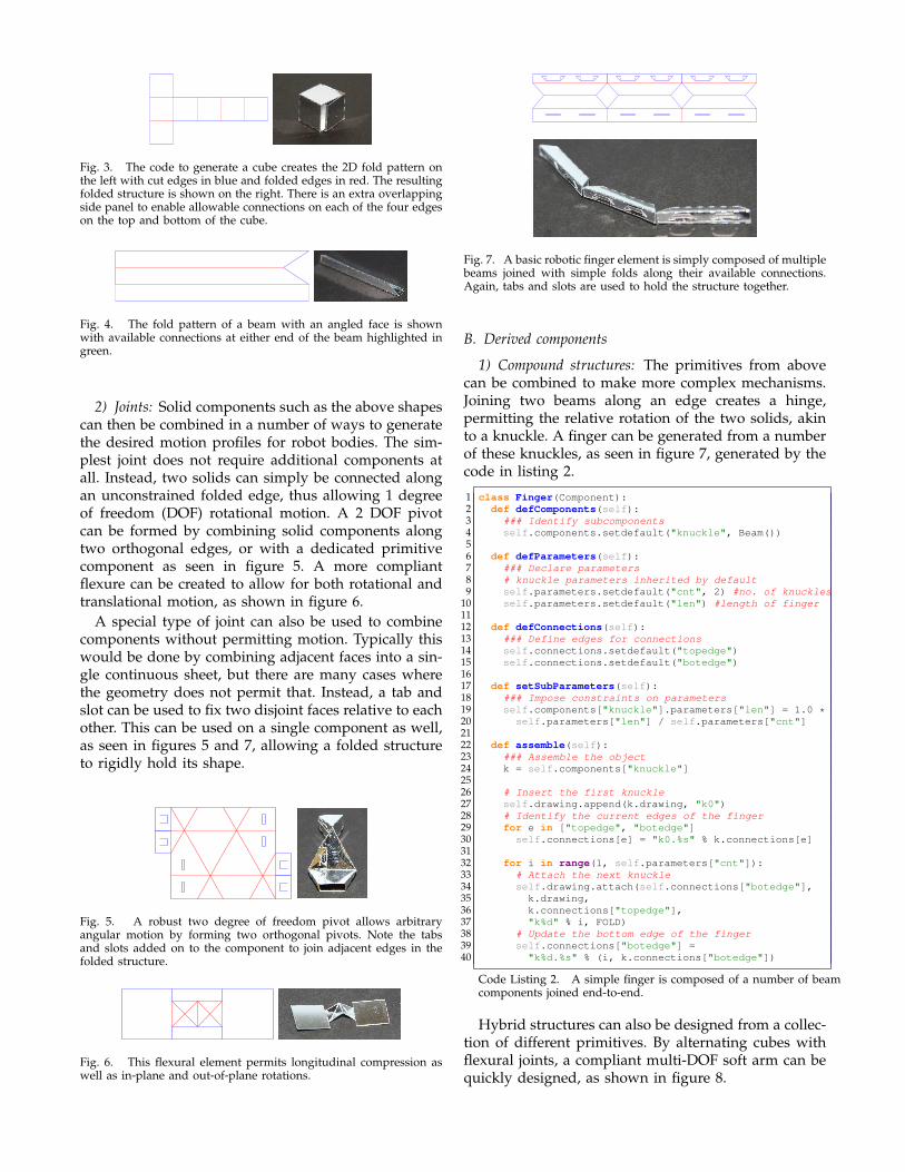
Fig. 3. The code to generate a cube creates the 2D fold pattern onthe left with cut edges in blue and folded edges in red. The resultingfolded structure is shown on the right. There is an extra overlappingside panel to enable allowable connections on each of the four edgeson the top and bottom of the cube.
Fig. 4. The fold pattern of a beam with an angled face is shownwith available connections at either end of the beam highlighted ingreen.
2) Joints: Solid components such as the above shapescan then be combined in a number of ways to generatethe desired motion profiles for robot bodies. The sim-plest joint does not require additional components atall. Instead, two solids can simply be connected alongan unconstrained folded edge, thus allowing 1 degreeof freedom (DOF) rotational motion. A 2 DOF pivotcan be formed by combining solid components alongtwo orthogonal edges, or with a dedicated primitivecomponent as seen in figure 5. A more compliantflexure can be created to allow for both rotational andtranslational motion, as shown in figure 6.
A special type of joint can also be used to combinecomponents without permitting motion. Typically thiswould be done by combining adjacent faces into a sin-gle continuous sheet, but there are many cases wherethe geometry does not permit that. Instead, a tab andslot can be used to fix two disjoint faces relative to eachother. This can be used on a single component as well,as seen in figures 5 and 7, allowing a folded structureto rigidly hold its shape.
Fig. 5. A robust two degree of freedom pivot allows arbitraryangular motion by forming two orthogonal pivots. Note the tabsand slots added on to the component to join adjacent edges in thefolded structure.
Fig. 6. This flexural element permits longitudinal compression aswell as in-plane and out-of-plane rotations.
Fig. 7. A basic robotic finger element is simply composed of multiplebeams joined with simple folds along their available connections.Again, tabs and slots are used to hold the structure together.
B. Derived components
1) Compound structures: The primitives from abovecan be combined to make more complex mechanisms.Joining two beams along an edge creates a hinge,permitting the relative rotation of the two solids, akinto a knuckle. A finger can be generated from a numberof these knuckles, as seen in figure 7, generated by thecode in listing 2.
1 class Finger(Component):
2 def defComponents(self):
3 ### Identify subcomponents
4 self.components.setdefault("knuckle", Beam())
56 def defParameters(self):
7 ### Declare parameters
8 # knuckle parameters inherited by default
9 self.parameters.setdefault("cnt", 2) #no. of knuckles
10 self.parameters.setdefault("len") #length of finger
1112 def defConnections(self):
13 ### Define edges for connections
14 self.connections.setdefault("topedge")
15 self.connections.setdefault("botedge")
1617 def setSubParameters(self):
18 ### Impose constraints on parameters
19 self.components["knuckle"].parameters["len"] = 1.0 *20 self.parameters["len"] / self.parameters["cnt"]
2122 def assemble(self):
23 ### Assemble the object
24 k = self.components["knuckle"]
2526 # Insert the first knuckle
27 self.drawing.append(k.drawing, "k0")
28 # Identify the current edges of the finger
29 for e in ["topedge", "botedge"]
30 self.connections[e] = "k0.%s" % k.connections[e]
3132 for i in range(1, self.parameters["cnt"]):
33 # Attach the next knuckle
34 self.drawing.attach(self.connections["botedge"],
35 k.drawing,
36 k.connections["topedge"],
37 "k%d" % i, FOLD)
38 # Update the bottom edge of the finger
39 self.connections["botedge"] =
40 "k%d.%s" % (i, k.connections["botedge"])
Code Listing 2. A simple finger is composed of a number of beamcomponents joined end-to-end.
Hybrid structures can also be designed from a collec-tion of different primitives. By alternating cubes withflexural joints, a compliant multi-DOF soft arm can bequickly designed, as shown in figure 8.

Fig. 8. Joining sequential cube faces with flexural joints allows 3DOF motion between each pair of cubes, creating a soft robot arm.Additional components, namely the tendons and their slots, werealso added into the design to allow for actuation of the arm.
Fig. 9. A number of fingers joined to the edges of a cube forms agripping hand. A 3D printed model of the central cube, generatedalongside the 2D fold pattern and assembled into the structure duringthe folding process as shown here, can provide rigidity to the device.
2) Robots bodies: These derived mechanisms can befurther refined and combined into complete robot bod-ies. By attaching a number of fingers onto the edges of asolid, a gripper is created as shown in figure 9. Variantsof the tabs, cube, and finger components were designedto produce this more sophisticated hand structure.Attaching this gripper onto the end of the compliantarm from above then yields a highly controllable ma-nipulator arm as shown in figure 10.
Designing this final complex robot took no more thancombining the relevant building blocks into structuresof ever increasing complexity, each step of the waycombining only a small number of previously designedcomponents to make the next mechanism. It is here thatthe power of this system is evident. The first pass foreach derivative component took less than an hour todesign, code, print, and fold, with subsequent designiterations happening much quicker. A full robot bodylike the manipulator arm could be assembled from acomponent library of only primitives in a small handfulof hours. If the library included any of the derivativeelements along the way, perhaps obtained through anopen source sharing community, the final design couldhave been reached even faster. For an expert designerfamiliar with the system, the primitives themselves aresimilarly quick to implement.
Fig. 10. Putting a gripper at the end of a flexible arm yields a truerobot body, a multi-degree of freedom manipulator arm, shown herebeing manually actuated.
C. Current component database
Over the course of creating bending, crawling,rolling, and flying robots, a number of componentswere designed and added to the component libraryto form an ever expanding database of designs. Mostcomponents in the library are quite simple, containingonly a few subcomponents. However, many containseveral levels of hierarchy, recursively building up fromset of primitives. In the current library, there are fewerthan 10 primitives defining solid objects, joints andhinges, connectors, and specialized geometries suchas mounts and wings. However, simple mechanismsform the first tier of compositional hierarchy, and fullfeatured robot bodies are already beginning to appearat the second tier. More complex robots, such as thatas diagrammed in figure 2 and shown in figure 10,may take more levels of nonetheless similarly simplecomponents.
VI. EXTENSIONS
The system as presented above is capable of generat-ing designs for printable robots of arbitrary complexityusing the folded plastic fabrication process. However,the system is not limited there. The scripted nature ofthe underlying robot representation allows for addi-tional functionality via further software development.
A. 3D printing
Though there are many benefits of the folded plasticprocess, it is not optimal for some applications. Inparticular, while lightness and flexibility is valuable forcreating moving parts, it is a detriment in situationswhere rigidity is necessary, for example when consider-ing energy efficiency in flying robots [9] or grip strengthin hand-like end effectors. However, since this systemproduces models of the 3D structures generated by anunfolding, it can also extract solid models to send to a3D printer. For example, in figure 9, a 3D printed modelof the cube forming the palm is co-designed along withthe fold pattern. The hybrid process can produce robotsmore versatile than either fabrication method alone.

Fig. 11. Mechanical bodies can include mounts for electromechanicaldevices; complete robots are then formed by installing a processorcontrolling servomotors to actuate the printed structures. Sensors canalso be incorporated to enable feedback control.
B. Electronics
Finally, to generate complete robots instead of robotbodies, the electrical subsystem needs to be includedwith the mechanical elements. In the robot examplespresented above, the designed degrees of freedom wereactuated by servomotors winding up cables tied tobody elements, as seen in figure 11. The mounts forthese servomotors, naturally, are designed as compo-nents attached to the final body design. However, thehardware controller, drivers, and application softwareare currently ad-hoc solutions added manually (in thecase of the above, the servos are driven by an Ar-duino or a GINA board [12] running custom writtenfirmware). Since the degrees of freedom of the robotalong with the specific drive actuators are specifiedby the mechanical body design, it should be possibleto automatically design these components as well, in-corporating electronic mounting and wiring into thegenerated design files that get fabricated.
VII. CONCLUSIONS
A. Contributions
The primary contribution of this work is a newend-to-end rapid design and fabrication paradigmthat specifies mechanical robot bodies by hierarchi-cally composing simpler components. An abstractionwas developed allowing for mechanical componentsto be described by scripts; a few designed primitivecomponents plus rules and algorithms for composi-tion were then sufficient to generate a wide array ofrobot mechanisms and bodies. This system was imple-mented in Python and used to generate design filesfor an origami-inspired plastic print-and-fold process.A database of primitive components was generated andused by the system to design and fabricate a numberof robot mechanisms of increasing sophistication andcomplexity.
B. Future work
In addition to extending this system to create robotdesigns of ever increasing functionality and complexity,there are additional avenues for research opened up bythe work initiated herein.
1) Design decomposition: The basis for this systemis the hierarchical modular design of robots by non-experts. However, there are many robot experts thatcan and do design custom robots (see for example[6]–[9]) to a much higher precision than achievableby a general multi-purpose system. It then becomesinteresting to see whether it is possible to decomposeexperts’ designs into parametrizable modules for usein this system. Big data techniques could potentially beapplied to extract useful reusable design componentsfrom complete designs, thus increasing the depth ofthe component library and expanding the scope ofdesignable robots.
2) Automated recommendations: Further analysis ofgenerated robot designs could also reveal details ofengineering principles. By evaluating existing robotstructures, it might be possible to build a recommen-dation engine into the design system, further reducingthe burden on a robot designer. As the corpus ofdesigned robots grows, so too does the engineeringknowledge contained in those designs, and the systemcould evolve from a tool to realize conceptual designsto a tool to propose new designs. Eventually, this leadsus down a path to a full fledged robot compiler, ableto produce complete robot designs from a specificationof the problem to be solved.
ACKNOWLEDGMENTS
The authors would like to acknowledge the contri-butions of Roger Lo and Ian Trase, whose assistance inthis project was invaluable.
REFERENCES
[1] J. Forlizzi and C. DiSalvo, “Service robots in the domesticenvironment: a study of the roomba vacuum in the home,” inProc. ACM SIGCHI/SIGART conf. on HRI, 2006, pp. 258–265.
[2] G. V. Lauder, “Flight of the robofly,” Nature, vol. 412, no. 16, pp.688–689, 2001.
[3] African robotics network (AFRON) - design challenge. [Online].Available: http://www.test.org/doe/
[4] 3D printing — MakerBot. [Online]. Available: http://www.makerbot.com/
[5] Thingiverse - digital design for physical objects. [Online].Available: http://www.thingiverse.com/
[6] C. D. Onal, M. T. Tolley, K. Koyanagi, R. J. Wood, and D. Rus,“Shape memory alloy actuation of a folded bio-inspired hexa-pod,” in in ATBio Workshop, IROS, 2012.
[7] C. D. Onal, R. J. Wood, and D. Rus, “An origami-inspired ap-proach to worm robots,” Mechatronics, IEEE/ASME Transactionson, vol. 18, no. 2, pp. 430–438, 2013.
[8] D. E. Soltero, B. J. Julian, C. D. Onal, and D. Rus, “A lightweightmodular 12-DOF print-and-fold hexapod,” in IROS, 2013 (toappear).
[9] A. Mehta, D. Rus, K. Mohta, Y. Mulgaonkar, M. Piccoli, andV. Kumar, “A scripted printable quadrotor: Rapid design andfabrication of a folded MAV,” 2013 (in review).
[10] S. M. Felton, M. T. Tolley, C. D. Onal, D. Rus, and R. J. Wood,“Robot self-assembly by folding: A printed inchworm robot,”in ICRA, 2013 (to appear).
[11] C. Sung, E. D. Demaine, M. L. Demaine, and D. Rus, “Joiningunfoldings of 3-D surfaces,” in ASME IDETC/CIE, 2013 (toappear).
[12] A. M. Mehta and K. S. Pister, “Warpwing: A complete opensource control platform for miniature robots,” in IROS. IEEE,2010, pp. 5169–5174.