an effective utilization of mxene and its effect on
TRANSCRIPT
RSC Advances
PAPER
Ope
n A
cces
s A
rtic
le. P
ublis
hed
on 0
8 Ja
nuar
y 20
20. D
ownl
oade
d on
1/2
5/20
22 1
:31:
47 A
M.
Thi
s ar
ticle
is li
cens
ed u
nder
a C
reat
ive
Com
mon
s A
ttrib
utio
n-N
onC
omm
erci
al 3
.0 U
npor
ted
Lic
ence
.
View Article OnlineView Journal | View Issue
An effective utili
aDivision of Bio-Nanochemistry, College of
Iksan 570-749, Korea. E-mail: raagulan
[email protected]; Fax: +82-63-841bDepartment of Chemical Engineering, Won
E-mail: [email protected] Electronics Technology Institute (KE
Center, Korea. E-mail: [email protected]; miydComposite Research Division, Korea Institu
South Korea. E-mail: [email protected]
† Electronic supplementary information (the composite and MXene under the scancross-section of the composite under theXPS O 1s Overlapping curve of compositcomposites from XPS. Table S2: Peak poXPS. Fig. S4: XPS of FCCNW, CCNW andd-MXene, u-MXene, MAX phase, CCNcomposites. Table S3: XRD peaks ofcomparison of composite in different ranshi. Fig. S8: (a–g) TGA and DTG analysithermal conductivity and heat capacThermogravimetric analysis (TG)thermogravimetry (DTG) analysis. TableS8: SEA of fabricated composites. Table SS10: The bandwidth comparison at aboS11: EMI shielding comparison of previoshort-listed EMI shielding compariso10.1039/c9ra09522e
Cite this: RSC Adv., 2020, 10, 1613
Received 15th November 2019Accepted 23rd December 2019
DOI: 10.1039/c9ra09522e
rsc.li/rsc-advances
This journal is © The Royal Society o
zation of MXene and its effect onelectromagnetic interference shielding: flexible,free-standing and thermally conductive compositefrom MXene–PAT–poly(p-aminophenol)–polyaniline co-polymer†
Kanthasamy Raagulan,a Ramanaskanda Braveenth,a Bo Mi Kim,b Kwang Jin Lim,c
Sang Bok Lee,d Miyoung Kim*c and Kyu Yun Chai *a
MXene and conductive polymers are attractive candidates for electromagnetic interference shielding (EMI)
applications. The MXene–PAT-conductive polymer (CP) composites were fabricated by a cost-effective
spray coating technique and characterized using X-ray photoelectron spectroscopy (XPS), scanning
electron microscopy (SEM), X-ray diffraction (XRD) and Raman spectroscopy. A new approach has been
developed for the synthesis of exfoliated MXene. The MXene–PAT–poly(p-aminophenol)–polyaniline co-
polymer composite exhibited good electric conductivity (EC) of 7.813 S cm�1. The composites revealed
an excellent thermal properties, which were 0.687 W (m K)�1 thermal conductivity, 2.247 J (g K)�1 heat
capacity, 0.282 mm2 s�1 thermal diffusivity and 1.330 W s1/2 m�2 K�1 thermal effusivity. The composites
showed 99.99% shielding efficiency and the MXene–PAT–PANI–PpAP composite (MXPATPA) had EMI
shielding effectiveness of 45.18 dB at 8.2 GHz. The reduced form of MXene (r-Ti3C2Tx) increased the
shielding effectiveness (SE) by 7.26% and the absorption (SEA) was greatly enhanced by the ant farm like
structure. The composites possess excellent thermal and EMI SE characteristics, thus can be applied in
areas, such as mobile phones, military utensils, heat-emitting electronic devices, automobiles and radars.
Natural Sciences, Wonkwang University,
@live.com; [email protected];
-4893; Tel: +82-63-850-6230
kwang University, Iksan 570-749, Korea.
TI), Researcher/IT Application Research
[email protected]; Tel: +82-63-219-0011
te of Materials Science, Changwon 51508,
ESI) available: Fig. S1: The topology ofning electron microscope. Fig. S2: Thescanning electron microscope. Fig. S3:es. Table S1: Elemental percentage ofsition of elements in composites fromdb-MXene. Fig. S5: XRD of df-MXene,W and FCCNW. Fig. S6: XRD ofcomposites. Fig. S7: Raman spectrage. Table S4: Peak position of Ramans of composites (h) thermal diffusivity,ity of the composites. Table S5:of the composites, derivative
S7: SE of fabricated composites. Table9: SER of fabricated composites. Tableut 99.99% shielding efficiency. Tableus work published and Table S12: Then for graph (Fig. 12e). See DOI:
f Chemistry 2020
1 Introduction
Widespread electromagnetic interference (EMI) is a demandingissue as a consequence of the rapid advancement of miniatureelectronic components and extensive usage of wirelesscommunication worldwide. The global growth in human pop-ulation together with the mass production of a variety of elec-tronic devices is creating electromagnetic pollution. EMI isa hot topic, due to the effect on the proximal biological andelectronic systems.1,2 In general, the passage of migrant birdsdramatically changes from year to year, due to electromagneticnoise (EMN), which disturbs the natural compass and magneticpositioning capability of migratory birds. Hence, EMN restrictsseasonal and natural habitant birds in rural, town, and wildareas.1–3 Furthermore, EMI also causes various health issues inhuman, such as headaches, chromosomal mutation, andnervous disorders.3 When electromagnetic radiation hitsa living organism, a dipole environment is created in the body,which creates additional potential, and diminishes the ionstransportation through nerves. EMI induces vibration of watermolecules, which releases extra heat energy, which is dissemi-nated among organs to generate physiological dysfunction,unhealthy infant, denature of protein, disorder in enzymefunction, non-regular function of organelles, and reduction of
RSC Adv., 2020, 10, 1613–1633 | 1613
RSC Advances Paper
Ope
n A
cces
s A
rtic
le. P
ublis
hed
on 0
8 Ja
nuar
y 20
20. D
ownl
oade
d on
1/2
5/20
22 1
:31:
47 A
M.
Thi
s ar
ticle
is li
cens
ed u
nder
a C
reat
ive
Com
mon
s A
ttrib
utio
n-N
onC
omm
erci
al 3
.0 U
npor
ted
Lic
ence
.View Article Online
fertility, which raise questions about the sustainability ofhuman and other living things on the Earth.4,5
EMI shielding is expressed in dB, and is inevitable in themodern electronic world.3 Non-Ionized Radiation (NIR) has beenwidely used, as it is safe, even though recent study reports thatsome NIR radiation has a detrimental issue on biotic structure.The NIR includes extremely low frequency, radio-frequency,microwaves, visible light, and some part of ultraviolet (UV),which can be categorized into perceptible and non-perceptibleradiation. The visible region is unharmful, whereas somefrequencies of imperceptible radiation potentially have consider-able inuence on human health. The electron moving materialsare the primary source of NIR, while the surrounding environmentis a scattering source of NIR.6–8 Thus, achieving electromagneticcompatibility is indispensable in the current norm. Electromag-netic noise is engendered by various sources, such as thermalbackground noise, EMI, and terrestrial noise. Diminishing orblocking electromagnetic noise without disturbing adjacentcomponents is considered to be electromagnetic compatibility.9,10
To accomplish good electromagnetic compatibility, scien-tists worldwide utilize numerous strategies by using variousmaterials, such as MXene, metal plate, textile, wax, noncon-ductive polymer matrix, carbon fabric, intrinsic conductivepolymer (ICP), graphite, graphene, carbon nanotube, nano-plate, nanoparticle, plant materials, carbon black, andcement.11–16 Nonconductive polymers, such as polyvinyl chlo-ride (PVC), nylon,17 polyvinylidene uoride (PVDF), poly-ethylene terephthalate (PET),18 polydimethylsiloxane (PDMS),19
polyethylene (PE),20 polypropylene (PP), polyurethane, andpolystyrene21 are used as supportive matrices for EMI shieldingapplications. ICPs, such as polyaniline (PANI),19 polypyrrole(PPy),22 and polythiophene,23 are used as a single matrix, or incombination. The combination of different materials is used tocreate different structural features with enhanced EMI shield-ing.17–28 Absorption, reection, and multiple reections arecentral factors for the EMI shielding behaviour of materials,where one aspect of the basic mechanism is more dominantthan others. Absorption can be enhanced by increasing thebipolarity of the composite, whereas reection depends on theelectric conductivity of the materials. Absorption happens dueto scattering, multiple reections, and electric and magneticbipolarity. Nanoparticles possess strong scattering ability, andare able to absorb different energy electromagnetic radiation.Multiple reections can be enhanced by layered structure andelectron ow. The dipolar environment can be created by usingpolar llers, and hollow and triangular nanomaterials. Unevenelectron distribution in hollow and triangular nanostructurecreates polar components that affect EMI shielding.19–23,29,30
Ti3C2Tx/co-doped polyaniline composite exhibits 36 dB of EMISE with 24.4 S cm�1. The co-doped shows 16 dB of EMI SE and0.3 S cm�1 of EC while pure polyaniline (PANI) exhibits 20 dB ofEMI SE and 0.213 S cm�1 of EC. In addition, carbon nanotube/polyaniline lms displays the EMI shielding of 74.9 dB with 7.5� 104 dB cm3 g�1 of SSE, 3009 S cm�1 of EC and thickness of0.029 mm. The MWCNT/PANI (Ku band), SWCNT/PANI (2–18GHz), MWCNT/PANI (0.8–3 GHz) composite show 39.2, 31.5, 47dB of EMI shielding and its corresponding thickness are 2, 2.4
1614 | RSC Adv., 2020, 10, 1613–1633
and 0.5 mm, respectively. PEDOT : PSS/waterborne polyurethane(WPU) composite exhibits EMI shielding of 62 dB with 0.15mm.24–28 Therefore, increasing thickness of the conductive poly-mer composites reduces the EMI shielding. Hence, conductivepolymer composition should be a thin lm.
MXene is a novel kind of two-dimensional ternary metalcarbide/nitride derived from the corresponding three-dimensionalMAX phase. The MXene possess excellent physical properties suchas hydrophilic in nature with good electrical and thermalconductivity, higher specic surface area and excellent lm form-ing ability which aremain reason for the preference ofMXene thangraphene. Hence, MXene and MXene composites become hottopic for EMI shielding application around the world. The varioustype of MXene have been studied and EMI shielding applicationmainly focus on Ti3C2Tx. The Shahzad et al. reported that theTi3C2Tx/sodium alginate coating with 45 mm on Polyethyleneterephthalate (PET) lm shows 92 dB of EMI SE with 4600 S cm�1
of electric conductivity.14,27,28 The ultralight MXene-based aerogelsexhibits 75 dB EMI shielding with SSE of 9904 dB g�1 cm3 anddensity of 0.004 g cm�3 where aerogel induced by freeze dryingprocess whileMXene Foam exhibits 70 dB of EMI SEwith 0.006 cmof thickness 0.22 g cm�3 density and SSE of 318 dB g�1 cm3 wherefoaming induce by hydrazine.16,24 Moreover, MXene/calcium algi-nate aerogel exhibits 54.3 dB of EMI shielding with SSE of 40.22 dBg�1. cm3, thickness 26 mm of and density of 1.35 g cm�3.25 Hence,introduction of polymers comparatively reduces the EMI shieldingof pureMXene, increase the density and give rise various structuralfeatures. The graphene/copper nanowire embedded grapheneaerogel exhibits 47 dB of EMI SE with 0.2 cm of thickness and ECof 1.208 S cm�1.26 The MXene polypyrrole (PPy) textile with thick-ness 1.3 mm (3 times coated) displays EMI SE of 90 dBwith 10 S cm�1 of EC whereas Ti3C2Tx/poly(3,4-ethyl-enedioxythiophene)–poly(styrenesulfonate) (PEDOT : PSS) (7 : 1)with 11.1 mm thickness and 340.5 S cm�1 of EC shows 42.1 dB ofEMI SE.12,13 Hence, the MXene is a good choice for EMI shieldingcompare to the other llers which is due to the MXene have lowdensity, high electric conductivity, high EMI shielding withmicronthickness.
The selective etching strategy has been used to synthesizeMXene, for which HF, LiF/HCl, FeF3/HCl, and NH4F/HCl are used.However, the minimally intensive layer delamination (MILD)method uses LiF/HCl, which gives rise to the best quality MXene,compared with other etchants.31 The general formula of MXene isMnXn+1Tx, while the correspondingMAX phase possessesMnAXn+1universal symbolization, where M is an early transition metals, Ais a group 13/14 element, X is carbon or nitrogen, and Tx isa surface functional group, which include –OH, –F, ]O and Cl.During the etching process, the A layer is eradicated, and thecorresponding bond between M–A and A–X are substituted by thesurface functional groups. Thus, the MXene is formed with thegap between 2 layers. One A layer is a sandwich between two M–Xlayers, where the M–X bond is stronger than the M–A bond.Hence, depletion of M–A bond is easier than of M–X bond, whichremains as MXene.31–35 So far, many MAX phases and MXeneshave been studied, even though Ti3AlC2 and its correspondingMXene are widely used for various applications, such as EMIshielding, battery, medical, and capacitors.31–36
This journal is © The Royal Society of Chemistry 2020
Paper RSC Advances
Ope
n A
cces
s A
rtic
le. P
ublis
hed
on 0
8 Ja
nuar
y 20
20. D
ownl
oade
d on
1/2
5/20
22 1
:31:
47 A
M.
Thi
s ar
ticle
is li
cens
ed u
nder
a C
reat
ive
Com
mon
s A
ttrib
utio
n-N
onC
omm
erci
al 3
.0 U
npor
ted
Lic
ence
.View Article Online
In this study, we developed a new type of polymer compo-sition called “PAT polymer” solution and a new approached hasbeen made to prepare exfoliated MXene (d-MXene) and reducedMXene (r-MXene). According to our knowledge, this is the rsttime that the conductive polymers (CP), such as poly(p-amino-phenol) (PpAP), polyaniline–PpAP (PANI–PpAP) copolymer wereemployed for EMI shielding application. We have prepared andanalyzed the effectiveness of other CPs, such as polypyrrole(PPy), polyaniline (PANI), polythiophene (PTh) for this study.The general formula of composite was MXPATCP; where MX isMXene, PAT is polymer composition and CP is conductivepolymer. Hence, MXPATPN, PXPATPA, MXPATPNPA,MXPATPPy and MXPATPTh composites were successfullyfabricated with corresponding conductive polymers, which arePANI, PpAP, PANI–PpAP, PPy and PTh, respectively. Thecomposites without CP are MXPAT, dMXPAT, uMXPAT andrMXPAT which were prepared by using MXene, d-MXene, u-MXene and r-MXene, respectively. The rMXPAT and dMXPATwere used to compare the EMI SE with other composites. Theconductive carbon ber network was denoted as CCNW andfunctionalized CCNW was denoted as FCCNW. The parameterssuch as elemental analysis, structural features, thermalstability, thermal conductivity, electric conductivity and EMIshielding were investigated in detail.
2 Materials and method2.1. Materials
Titanium, Titanium carbide, and aluminium (325 mesh size)were purchased fromMaterials Korea (Rep. of Korea). Graphene(M-25, average size of 25 mm) was obtained from Ditto Tech-nology (Rep. of Korea). Ethanol (98%), agar, hydrochloric acid(HCl 35%), tetrahydro furan (THF), and aniline were suppliedby Samchun (Seoul, Korea). Polyethylene terephthalate (PET)binder (bre diameter 2.2 dtex, 5 mm) and carbon bre (brediameter 7 mm, 6 mm length) were obtained from TORAYproduct, (Tokyo, Japan), while polyacrylamide (PAM) waspurchased from Sigma Aldrich (Seoul, South Korea). Iron(III)chloride (FeCl3 97%), lithium uoride (LiF 300 mesh), pyrrole(98%), thiophene (99%), trimesic acid (98%), 4-aminophenol(98%), acrylic acid, N-methyl-2-pyrrolidone (NMP), and poly-acrylic acid (PAA) were obtained from Sigma Aldrich (Seoul,South Korea). Polyvinyl alcohol (PVA 89%) and polyvinylideneuoride (PVDF) were supplied by Alfa Aesar (Seoul, Korea).Chitiooligosaccharide (10 000 MW) was provided by SunchonNational University, Biomedical polymer lab, (Jeonju Korea).Glycerin was obtained by reagent from Duksan (Seoul Korea).N,N-Dimethylformamide (DMF) was purchased from Daejung(Seoul Korea). All of the chemicals were used without furtherpurication.
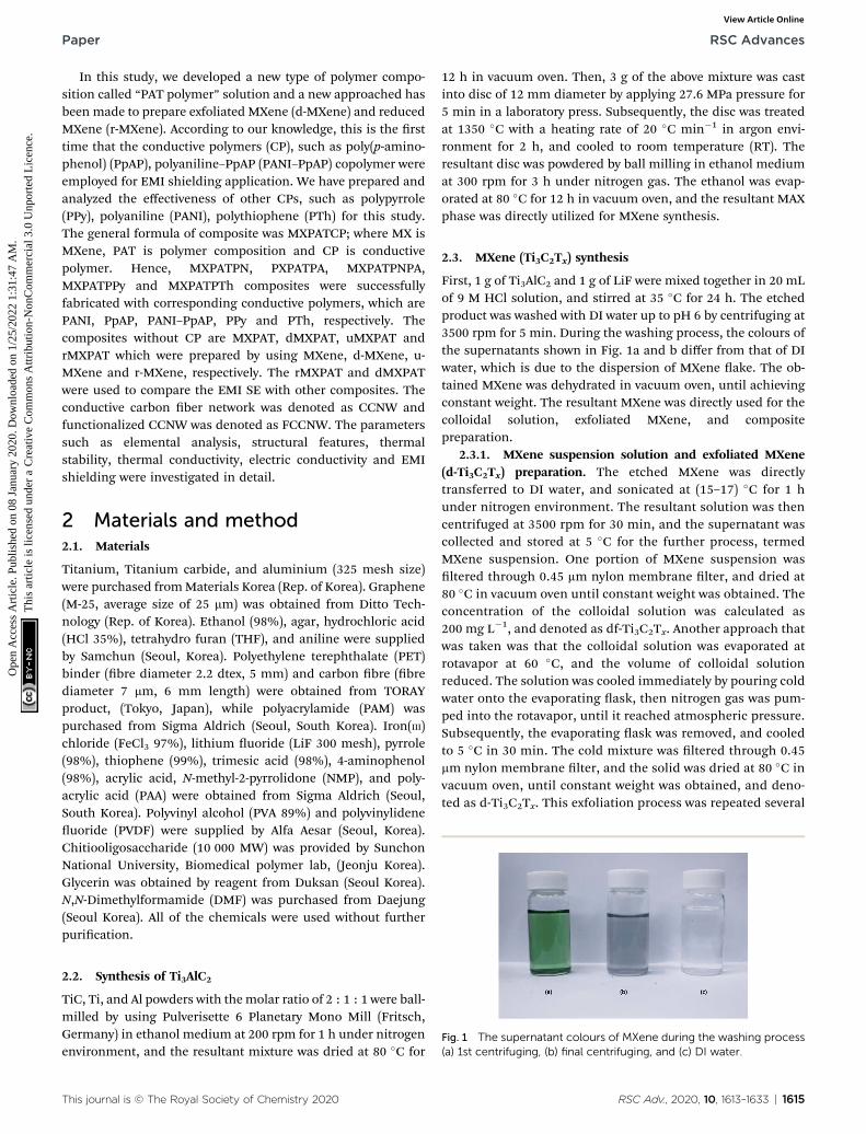
Fig. 1 The supernatant colours of MXene during the washing process(a) 1st centrifuging, (b) final centrifuging, and (c) DI water.
2.2. Synthesis of Ti3AlC2
TiC, Ti, and Al powders with themolar ratio of 2 : 1 : 1 were ball-milled by using Pulverisette 6 Planetary Mono Mill (Fritsch,Germany) in ethanol medium at 200 rpm for 1 h under nitrogenenvironment, and the resultant mixture was dried at 80 �C for
This journal is © The Royal Society of Chemistry 2020
12 h in vacuum oven. Then, 3 g of the above mixture was castinto disc of 12 mm diameter by applying 27.6 MPa pressure for5 min in a laboratory press. Subsequently, the disc was treatedat 1350 �C with a heating rate of 20 �C min�1 in argon envi-ronment for 2 h, and cooled to room temperature (RT). Theresultant disc was powdered by ball milling in ethanol mediumat 300 rpm for 3 h under nitrogen gas. The ethanol was evap-orated at 80 �C for 12 h in vacuum oven, and the resultant MAXphase was directly utilized for MXene synthesis.
2.3. MXene (Ti3C2Tx) synthesis
First, 1 g of Ti3AlC2 and 1 g of LiF were mixed together in 20 mLof 9 M HCl solution, and stirred at 35 �C for 24 h. The etchedproduct was washed with DI water up to pH 6 by centrifuging at3500 rpm for 5 min. During the washing process, the colours ofthe supernatants shown in Fig. 1a and b differ from that of DIwater, which is due to the dispersion of MXene ake. The ob-tained MXene was dehydrated in vacuum oven, until achievingconstant weight. The resultant MXene was directly used for thecolloidal solution, exfoliated MXene, and compositepreparation.
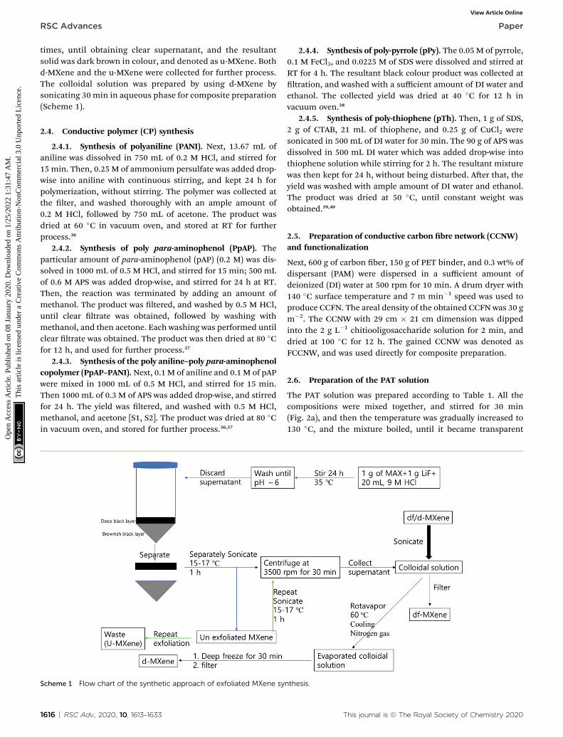
2.3.1. MXene suspension solution and exfoliated MXene(d-Ti3C2Tx) preparation. The etched MXene was directlytransferred to DI water, and sonicated at (15–17) �C for 1 hunder nitrogen environment. The resultant solution was thencentrifuged at 3500 rpm for 30 min, and the supernatant wascollected and stored at 5 �C for the further process, termedMXene suspension. One portion of MXene suspension wasltered through 0.45 mm nylon membrane lter, and dried at80 �C in vacuum oven until constant weight was obtained. Theconcentration of the colloidal solution was calculated as200 mg L�1, and denoted as df-Ti3C2Tx. Another approach thatwas taken was that the colloidal solution was evaporated atrotavapor at 60 �C, and the volume of colloidal solutionreduced. The solution was cooled immediately by pouring coldwater onto the evaporating ask, then nitrogen gas was pum-ped into the rotavapor, until it reached atmospheric pressure.Subsequently, the evaporating ask was removed, and cooledto 5 �C in 30 min. The cold mixture was ltered through 0.45mm nylon membrane lter, and the solid was dried at 80 �C invacuum oven, until constant weight was obtained, and deno-ted as d-Ti3C2Tx. This exfoliation process was repeated several
RSC Adv., 2020, 10, 1613–1633 | 1615
RSC Advances Paper
Ope
n A
cces
s A
rtic
le. P
ublis
hed
on 0
8 Ja
nuar
y 20
20. D
ownl
oade
d on
1/2
5/20
22 1
:31:
47 A
M.
Thi
s ar
ticle
is li
cens
ed u
nder
a C
reat
ive
Com
mon
s A
ttrib
utio
n-N
onC
omm
erci
al 3
.0 U
npor
ted
Lic
ence
.View Article Online
times, until obtaining clear supernatant, and the resultantsolid was dark brown in colour, and denoted as u-MXene. Bothd-MXene and the u-MXene were collected for further process.The colloidal solution was prepared by using d-MXene bysonicating 30 min in aqueous phase for composite preparation(Scheme 1).
2.4. Conductive polymer (CP) synthesis
2.4.1. Synthesis of polyaniline (PANI). Next, 13.67 mL ofaniline was dissolved in 750 mL of 0.2 M HCl, and stirred for15 min. Then, 0.25 M of ammonium persulfate was added drop-wise into aniline with continuous stirring, and kept 24 h forpolymerization, without stirring. The polymer was collected atthe lter, and washed thoroughly with an ample amount of0.2 M HCl, followed by 750 mL of acetone. The product wasdried at 60 �C in vacuum oven, and stored at RT for furtherprocess.36
2.4.2. Synthesis of poly para-aminophenol (PpAP). Theparticular amount of para-aminophenol (pAP) (0.2 M) was dis-solved in 1000 mL of 0.5 M HCl, and stirred for 15 min; 500 mLof 0.6 M APS was added drop-wise, and stirred for 24 h at RT.Then, the reaction was terminated by adding an amount ofmethanol. The product was ltered, and washed by 0.5 M HCl,until clear ltrate was obtained, followed by washing withmethanol, and then acetone. Each washing was performed untilclear ltrate was obtained. The product was then dried at 80 �Cfor 12 h, and used for further process.37
2.4.3. Synthesis of the poly aniline–poly para-aminophenolcopolymer (PpAP–PANI). Next, 0.1 M of aniline and 0.1 M of pAPwere mixed in 1000 mL of 0.5 M HCl, and stirred for 15 min.Then 1000 mL of 0.3 M of APS was added drop-wise, and stirredfor 24 h. The yield was ltered, and washed with 0.5 M HCl,methanol, and acetone [S1, S2]. The product was dried at 80 �Cin vacuum oven, and stored for further process.36,37
Scheme 1 Flow chart of the synthetic approach of exfoliated MXene sy
1616 | RSC Adv., 2020, 10, 1613–1633
2.4.4. Synthesis of poly-pyrrole (pPy). The 0.05 M of pyrrole,0.1 M FeCl3, and 0.0225 M of SDS were dissolved and stirred atRT for 4 h. The resultant black colour product was collected atltration, and washed with a sufficient amount of DI water andethanol. The collected yield was dried at 40 �C for 12 h invacuum oven.38
2.4.5. Synthesis of poly-thiophene (pTh). Then, 1 g of SDS,2 g of CTAB, 21 mL of thiophene, and 0.25 g of CuCl2 weresonicated in 500 mL of DI water for 30 min. The 90 g of APS wasdissolved in 500 mL DI water which was added drop-wise intothiophene solution while stirring for 2 h. The resultant mixturewas then kept for 24 h, without being disturbed. Aer that, theyield was washed with ample amount of DI water and ethanol.The product was dried at 50 �C, until constant weight wasobtained.39,40
2.5. Preparation of conductive carbon bre network (CCNW)and functionalization
Next, 600 g of carbon ber, 150 g of PET binder, and 0.3 wt% ofdispersant (PAM) were dispersed in a sufficient amount ofdeionized (DI) water at 500 rpm for 10 min. A drum dryer with140 �C surface temperature and 7 m min�1 speed was used toproduce CCFN. The areal density of the obtained CCFN was 30 gm�2. The CCNW with 29 cm � 21 cm dimension was dippedinto the 2 g L�1 chitiooligosaccharide solution for 2 min, anddried at 100 �C for 12 h. The gained CCNW was denoted asFCCNW, and was used directly for composite preparation.
2.6. Preparation of the PAT solution
The PAT solution was prepared according to Table 1. All thecompositions were mixed together, and stirred for 30 min(Fig. 2a), and then the temperature was gradually increased to130 �C, and the mixture boiled, until it became transparent
nthesis.
This journal is © The Royal Society of Chemistry 2020
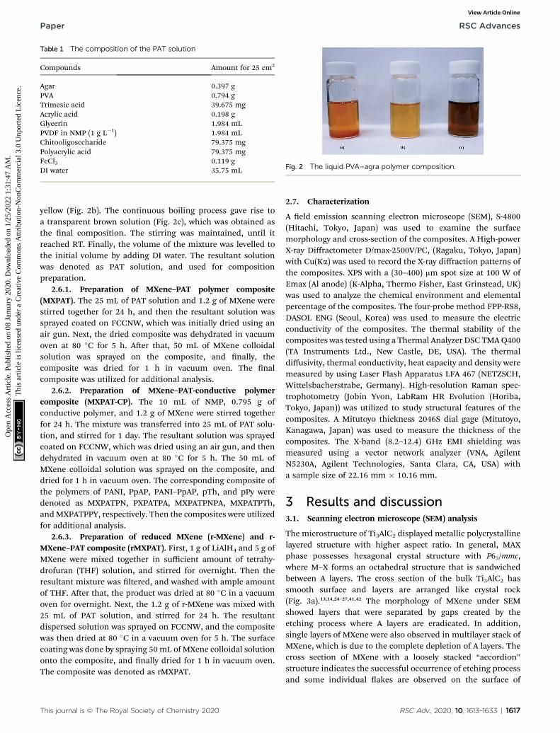
Table 1 The composition of the PAT solution
Compounds Amount for 25 cm2
Agar 0.397 gPVA 0.794 gTrimesic acid 39.675 mgAcrylic acid 0.198 gGlycerin 1.984 mLPVDF in NMP (1 g L�1) 1.984 mLChitooligosccharide 79.375 mgPolyacrylic acid 79.375 mgFeCl3 0.119 gDI water 35.75 mL Fig. 2 The liquid PVA–agra polymer composition.
Paper RSC Advances
Ope
n A
cces
s A
rtic
le. P
ublis
hed
on 0
8 Ja
nuar
y 20
20. D
ownl
oade
d on
1/2
5/20
22 1
:31:
47 A
M.
Thi
s ar
ticle
is li
cens
ed u
nder
a C
reat
ive
Com
mon
s A
ttrib
utio
n-N
onC
omm
erci
al 3
.0 U
npor
ted
Lic
ence
.View Article Online
yellow (Fig. 2b). The continuous boiling process gave rise toa transparent brown solution (Fig. 2c), which was obtained asthe nal composition. The stirring was maintained, until itreached RT. Finally, the volume of the mixture was levelled tothe initial volume by adding DI water. The resultant solutionwas denoted as PAT solution, and used for compositionpreparation.
2.6.1. Preparation of MXene–PAT polymer composite(MXPAT). The 25 mL of PAT solution and 1.2 g of MXene werestirred together for 24 h, and then the resultant solution wassprayed coated on FCCNW, which was initially dried using anair gun. Next, the dried composite was dehydrated in vacuumoven at 80 �C for 5 h. Aer that, 50 mL of MXene colloidalsolution was sprayed on the composite, and nally, thecomposite was dried for 1 h in vacuum oven. The nalcomposite was utilized for additional analysis.
2.6.2. Preparation of MXene–PAT-conductive polymercomposite (MXPAT-CP). The 10 mL of NMP, 0.795 g ofconductive polymer, and 1.2 g of MXene were stirred togetherfor 24 h. The mixture was transferred into 25 mL of PAT solu-tion, and stirred for 1 day. The resultant solution was sprayedcoated on FCCNW, which was dried using an air gun, and thendehydrated in vacuum oven at 80 �C for 5 h. The 50 mL ofMXene colloidal solution was sprayed on the composite, anddried for 1 h in vacuum oven. The corresponding composite ofthe polymers of PANI, PpAP, PANI–PpAP, pTh, and pPy weredenoted as MXPATPN, PXPATPA, MXPATPNPA, MXPATPTh,andMXPATPPY, respectively. Then the composites were utilizedfor additional analysis.
2.6.3. Preparation of reduced MXene (r-MXene) and r-MXene–PAT composite (rMXPAT). First, 1 g of LiAlH4 and 5 g ofMXene were mixed together in sufficient amount of tetrahy-drofuran (THF) solution, and stirred for overnight. Then theresultant mixture was ltered, and washed with ample amountof THF. Aer that, the product was dried at 80 �C in a vacuumoven for overnight. Next, the 1.2 g of r-MXene was mixed with25 mL of PAT solution, and stirred for 24 h. The resultantdispersed solution was sprayed on FCCNW, and the compositewas then dried at 80 �C in a vacuum oven for 5 h. The surfacecoating was done by spraying 50 mL of MXene colloidal solutiononto the composite, and nally dried for 1 h in vacuum oven.The composite was denoted as rMXPAT.
This journal is © The Royal Society of Chemistry 2020
2.7. Characterization
A eld emission scanning electron microscope (SEM), S-4800(Hitachi, Tokyo, Japan) was used to examine the surfacemorphology and cross-section of the composites. A High-powerX-ray Diffractometer D/max-2500V/PC, (Ragaku, Tokyo, Japan)with Cu(Ka) was used to record the X-ray diffraction patterns ofthe composites. XPS with a (30–400) mm spot size at 100 W ofEmax (Al anode) (K-Alpha, Thermo Fisher, East Grinstead, UK)was used to analyze the chemical environment and elementalpercentage of the composites. The four-probe method FPP-RS8,DASOL ENG (Seoul, Korea) was used to measure the electricconductivity of the composites. The thermal stability of thecomposites was tested using a Thermal Analyzer DSC TMAQ400(TA Instruments Ltd., New Castle, DE, USA). The thermaldiffusivity, thermal conductivity, heat capacity and density weremeasured by using Laser Flash Apparatus LFA 467 (NETZSCH,Wittelsbacherstrabe, Germany). High-resolution Raman spec-trophotometry (Jobin Yvon, LabRam HR Evolution (Horiba,Tokyo, Japan)) was utilized to study structural features of thecomposites. A Mitutoyo thickness 2046S dial gage (Mitutoyo,Kanagawa, Japan) was used to measure the thickness of thecomposites. The X-band (8.2–12.4) GHz EMI shielding wasmeasured using a vector network analyzer (VNA, AgilentN5230A, Agilent Technologies, Santa Clara, CA, USA) witha sample size of 22.16 mm � 10.16 mm.
3 Results and discussion3.1. Scanning electron microscope (SEM) analysis
The microstructure of Ti3AlC2 displayed metallic polycrystallinelayered structure with higher aspect ratio. In general, MAXphase possesses hexagonal crystal structure with P63/mmc,where M–X forms an octahedral structure that is sandwichedbetween A layers. The cross section of the bulk Ti3AlC2 hassmooth surface and layers are arranged like crystal rock(Fig. 3a).13,14,24–27,41,42 The morphology of MXene under SEMshowed layers that were separated by gaps created by theetching process where A layers are eradicated. In addition,single layers of MXene were also observed in multilayer stack ofMXene, which is due to the complete depletion of A layers. Thecross section of MXene with a loosely stacked “accordion”structure indicates the successful occurrence of etching processand some individual akes are observed on the surface of
RSC Adv., 2020, 10, 1613–1633 | 1617
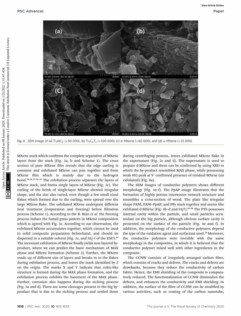
Fig. 3 SEM image of (a) Ti3AlC2 (�50 000), (b) Ti3C2Tx (�100 000), (c) d-MXene (�60 000), and (d) u-MXene (�15 000).
RSC Advances Paper
Ope
n A
cces
s A
rtic
le. P
ublis
hed
on 0
8 Ja
nuar
y 20
20. D
ownl
oade
d on
1/2
5/20
22 1
:31:
47 A
M.
Thi
s ar
ticle
is li
cens
ed u
nder
a C
reat
ive
Com
mon
s A
ttrib
utio
n-N
onC
omm
erci
al 3
.0 U
npor
ted
Lic
ence
.View Article Online
MXene stack which conrms the complete separation of MXenelayers from the stack (Fig. 3a, b and Scheme 1). The crosssection of pure MXene lm reveals that the edge curling iscommon and exfoliated MXene can join together and formMXene lm which is mainly due to the hydrogenbond.14,24–27,41–43 The exfoliation process separates the layers ofMXene stack, and forms single layers of MXene (Fig. 3c). Thecurling of the brink of single-layer MXene showed irregularshape, and the size also varied, even though a few small sizedakes which formed due to the curling, were spread over thelarge MXene ake. The exfoliated MXene undergone differentheat treatment (evaporation and freezing) before ltrationprocess (Scheme 1). According to the R. Bian et al. the freezingprocess induce the foxtail grass pattern in MXene compositionwhich is agreed with Fig. 3c. According to our observation, theexfoliated MXene accumulates together, which cannot be usedin solid composite preparation beforehand, and should bedispersed in a suitable solvent (Fig. 3c, and S1j–l of the ESI†).44
The incessant exfoliation of MXene nally yields non-layered by-product, where we can predict the basic mechanism of MAXphase and MXene formation (Scheme 2). Further, the MXenemade up of different size of layers and breaks in to the akesduring exfoliation process, and leaves the mark identied by Zon the origin. The marks X and Y indicate that cubic-likestructure is formed during the MAX phase formation, and theexfoliation process exhibits the basement of the MAX phase.Further, corrosion also happens during the etching process(Fig. 3a and d). There are some cleavages present in the big by-product that is due to the etching process and settled down
1618 | RSC Adv., 2020, 10, 1613–1633
during centrifuging process, leaves exfoliated MXene ake inthe supernatant (Fig. 3c and d). The supernatant is used toprepare d-MXene and these can be conrmed by using XRD inwhich the by-product resembled MAX phase, while possessingweak 002 peak at 9� conrmed presence of residual MXene (unexfoliated) (Fig. 8a).
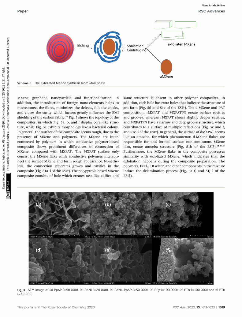
The SEM images of conductive polymers shows differentmorphology (Fig. 4a–f). The PpAP image illustrates that theformation of highly porous interwoven network structure andresembles a cross-section of wood. The plate like irregularshape PANI, PANI–PpAP, and PPy stack together and seems likeexfoliated d-MXene (Fig. 4b–d and S1j†).36–38 The PTh possessesinternal cavity within the particle, and small particles accu-mulate on the big particle, although obvious surface cavity ispresented on the surface of the particle (Fig. 4e and f). Inaddition, the morphology of the conductive polymers dependthe type of the oxidation agent and surfactant used.38 Moreover,the conductive polymers were invisible with the samemorphology in the composites, in which it is believed that theconductive polymer mixed well with other ingredients in thecomposite.
The CCNW consists of irregularly arranged carbon bre,which consists of cracks and defects. The cracks and defects aredrawbacks, because they reduce the conductivity of carbonfabric. Hence, the EMI shielding of the composite is compara-tively reduced. The functionalization of CCNW diminishes thedefects, and enhances the conductivity and EMI shielding. Inaddition, the surface of the bre of CCNW can be modied byvarious activities, such as coating of the carbon nanotube,
This journal is © The Royal Society of Chemistry 2020
Scheme 2 The exfoliated MXene synthesis from MAX phase.
Paper RSC Advances
Ope
n A
cces
s A
rtic
le. P
ublis
hed
on 0
8 Ja
nuar
y 20
20. D
ownl
oade
d on
1/2
5/20
22 1
:31:
47 A
M.
Thi
s ar
ticle
is li
cens
ed u
nder
a C
reat
ive
Com
mon
s A
ttrib
utio
n-N
onC
omm
erci
al 3
.0 U
npor
ted
Lic
ence
.View Article Online
MXene, graphene, nanoparticle, and functionalization. Inaddition, the introduction of foreign nano-elements helps tointerconnect the bres, minimizes the defects, lls the cracks,and closes the cavity, which factors greatly inuence the EMIshielding of the carbon fabric.45 Fig. 5 shows the topology of thecomposites, in which Fig. 5a, b, and f display coral-like struc-ture, while Fig. 5c exhibits morphology like a bacterial colony.In general, the surface of the composite seems rough, due to thepresence of MXene and polymers. The MXene are inter-connected by polymers in which conductive polymer-basedcomposite shows prominent differences in connection ofMXene, compared with MXPAT. The MXPAT surface onlyconsist the MXene ake while conductive polymers intercon-nect the surface MXene and form rough appearance. Nonethe-less, the connection generates groves and cavities in thecomposite (Fig. S1a–i of the ESI†). The polypyrrole-basedMXenecomposite consists of hole which creates nest-like edice and
Fig. 4 SEM image of (a) PpAP (�50 000), (b) PANI (�20 000), (c) PANI–(�30 000).
This journal is © The Royal Society of Chemistry 2020
same structure is absent in other polymer composites. Inaddition, each hole has extra holes that indicate the structure ofant farm (Fig. 5d and S1e of the ESI†). The d-MXene and PATcomposition, rMXPAT and MXPATPN create surface cavitiesand grooves, whereas rMXPAT shows slightly deeper cavities,and MXPATPN have a narrow and deep groove structure, whichcontributes to a surface of multiple reections (Fig. 5e and f,and S1e–i of the ESI†). In general, the surface of dMXPAT seemslike an amoeba, for which phenomenon d-MXene akes areresponsible for and formed surface non-continuous MXenelm, create amoeba structure (Fig. S1h of the ESI†).14,46,47
Furthermore, the MXene ake in the composite possessessimilarity with exfoliated MXene, which indicates that theexfoliation happens during the composite preparation. Thepolymers, FeCl3, DI water, and other components in the mixtureinduce the delamination process (Fig. 5a–f, and S1j–l of theESI†).
PpAP (�50 000), (d) PPy (�100 000), (e) PTh (�100 000) and (f) PTh
RSC Adv., 2020, 10, 1613–1633 | 1619
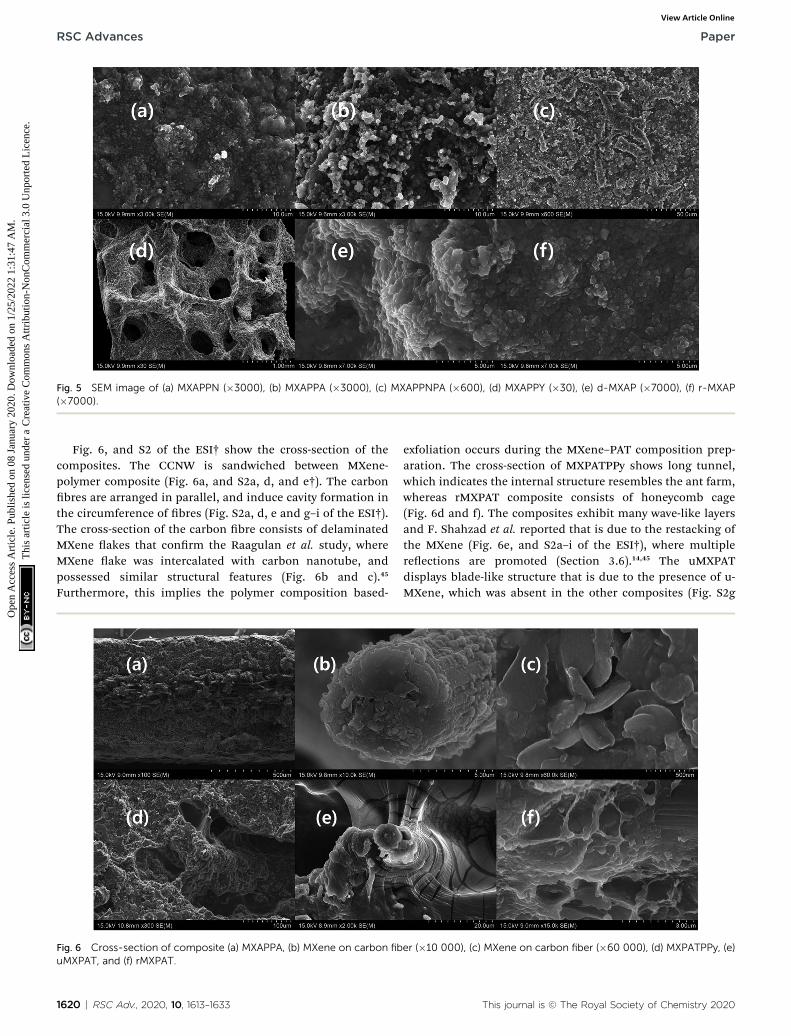
Fig. 5 SEM image of (a) MXAPPN (�3000), (b) MXAPPA (�3000), (c) MXAPPNPA (�600), (d) MXAPPY (�30), (e) d-MXAP (�7000), (f) r-MXAP(�7000).
RSC Advances Paper
Ope
n A
cces
s A
rtic
le. P
ublis
hed
on 0
8 Ja
nuar
y 20
20. D
ownl
oade
d on
1/2
5/20
22 1
:31:
47 A
M.
Thi
s ar
ticle
is li
cens
ed u
nder
a C
reat
ive
Com
mon
s A
ttrib
utio
n-N
onC
omm
erci
al 3
.0 U
npor
ted
Lic
ence
.View Article Online
Fig. 6, and S2 of the ESI† show the cross-section of thecomposites. The CCNW is sandwiched between MXene-polymer composite (Fig. 6a, and S2a, d, and e†). The carbonbres are arranged in parallel, and induce cavity formation inthe circumference of bres (Fig. S2a, d, e and g–i of the ESI†).The cross-section of the carbon bre consists of delaminatedMXene akes that conrm the Raagulan et al. study, whereMXene ake was intercalated with carbon nanotube, andpossessed similar structural features (Fig. 6b and c).45
Furthermore, this implies the polymer composition based-
Fig. 6 Cross-section of composite (a) MXAPPA, (b) MXene on carbon fibuMXPAT, and (f) rMXPAT.
1620 | RSC Adv., 2020, 10, 1613–1633
exfoliation occurs during the MXene–PAT composition prep-aration. The cross-section of MXPATPPy shows long tunnel,which indicates the internal structure resembles the ant farm,whereas rMXPAT composite consists of honeycomb cage(Fig. 6d and f). The composites exhibit many wave-like layersand F. Shahzad et al. reported that is due to the restacking ofthe MXene (Fig. 6e, and S2a–i of the ESI†), where multiplereections are promoted (Section 3.6).14,45 The uMXPATdisplays blade-like structure that is due to the presence of u-MXene, which was absent in the other composites (Fig. S2g
er (�10 000), (c) MXene on carbon fiber (�60 000), (d) MXPATPPy, (e)
This journal is © The Royal Society of Chemistry 2020
Paper RSC Advances
Ope
n A
cces
s A
rtic
le. P
ublis
hed
on 0
8 Ja
nuar
y 20
20. D
ownl
oade
d on
1/2
5/20
22 1
:31:
47 A
M.
Thi
s ar
ticle
is li
cens
ed u
nder
a C
reat
ive
Com
mon
s A
ttrib
utio
n-N
onC
omm
erci
al 3
.0 U
npor
ted
Lic
ence
.View Article Online
of the ESI†). The cavities in uMXPAT leave continuous layeredinterfaces that end up in carbon bre (Fig. 6e and S2I of theESI†). Possessing the abovementioned structure and u-MXeneleads to good thermal conductive material (Section 3.5).
3.2. X-ray photoelectron spectroscopy (XPS)
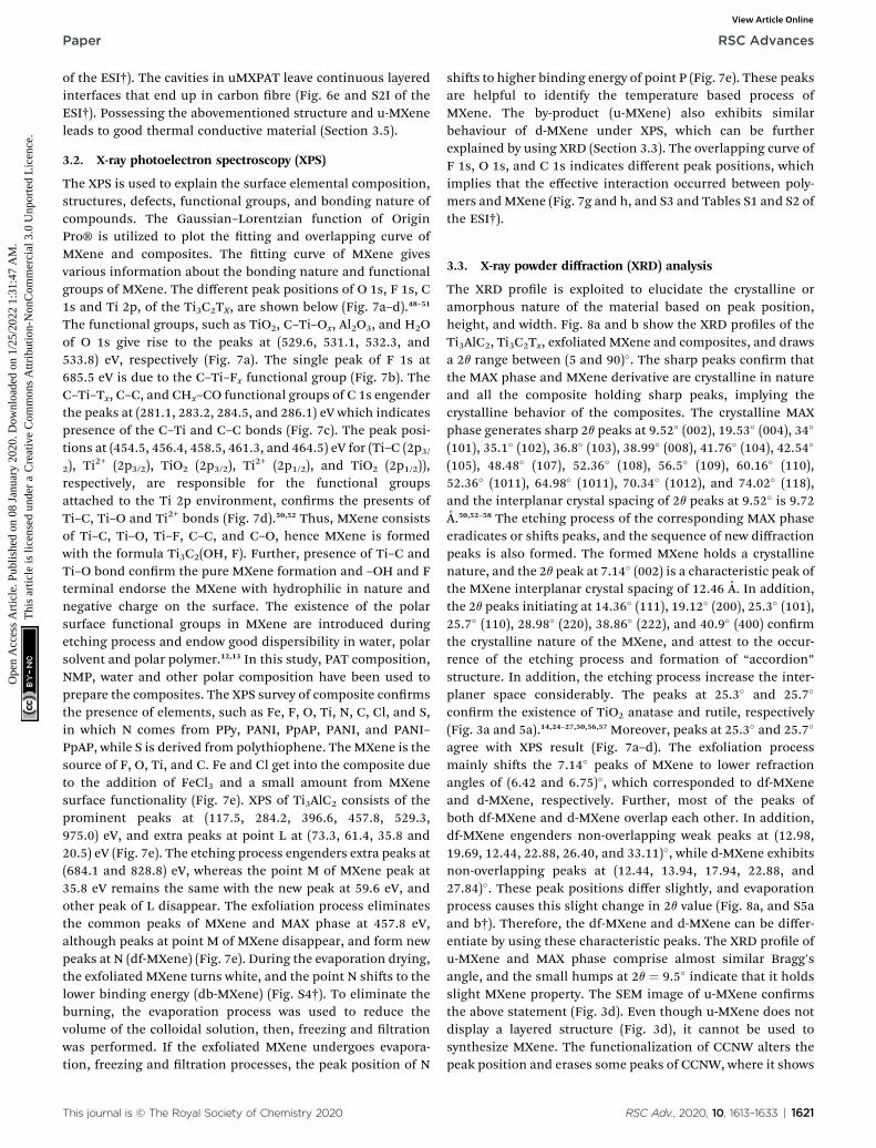
The XPS is used to explain the surface elemental composition,structures, defects, functional groups, and bonding nature ofcompounds. The Gaussian–Lorentzian function of OriginPro® is utilized to plot the tting and overlapping curve ofMXene and composites. The tting curve of MXene givesvarious information about the bonding nature and functionalgroups of MXene. The different peak positions of O 1s, F 1s, C1s and Ti 2p, of the Ti3C2TX, are shown below (Fig. 7a–d).48–51
The functional groups, such as TiO2, C–Ti–Ox, Al2O3, and H2Oof O 1s give rise to the peaks at (529.6, 531.1, 532.3, and533.8) eV, respectively (Fig. 7a). The single peak of F 1s at685.5 eV is due to the C–Ti–Fx functional group (Fig. 7b). TheC–Ti–Tx, C–C, and CHx–CO functional groups of C 1s engenderthe peaks at (281.1, 283.2, 284.5, and 286.1) eV which indicatespresence of the C–Ti and C–C bonds (Fig. 7c). The peak posi-tions at (454.5, 456.4, 458.5, 461.3, and 464.5) eV for (Ti–C (2p3/2), Ti2+ (2p3/2), TiO2 (2p3/2), Ti2+ (2p1/2), and TiO2 (2p1/2)),respectively, are responsible for the functional groupsattached to the Ti 2p environment, conrms the presents ofTi–C, Ti–O and Ti2+ bonds (Fig. 7d).50,52 Thus, MXene consistsof Ti–C, Ti–O, Ti–F, C–C, and C–O, hence MXene is formedwith the formula Ti3C2(OH, F). Further, presence of Ti–C andTi–O bond conrm the pure MXene formation and –OH and Fterminal endorse the MXene with hydrophilic in nature andnegative charge on the surface. The existence of the polarsurface functional groups in MXene are introduced duringetching process and endow good dispersibility in water, polarsolvent and polar polymer.12,13 In this study, PAT composition,NMP, water and other polar composition have been used toprepare the composites. The XPS survey of composite conrmsthe presence of elements, such as Fe, F, O, Ti, N, C, Cl, and S,in which N comes from PPy, PANI, PpAP, PANI, and PANI–PpAP, while S is derived from polythiophene. The MXene is thesource of F, O, Ti, and C. Fe and Cl get into the composite dueto the addition of FeCl3 and a small amount from MXenesurface functionality (Fig. 7e). XPS of Ti3AlC2 consists of theprominent peaks at (117.5, 284.2, 396.6, 457.8, 529.3,975.0) eV, and extra peaks at point L at (73.3, 61.4, 35.8 and20.5) eV (Fig. 7e). The etching process engenders extra peaks at(684.1 and 828.8) eV, whereas the point M of MXene peak at35.8 eV remains the same with the new peak at 59.6 eV, andother peak of L disappear. The exfoliation process eliminatesthe common peaks of MXene and MAX phase at 457.8 eV,although peaks at point M of MXene disappear, and form newpeaks at N (df-MXene) (Fig. 7e). During the evaporation drying,the exfoliated MXene turns white, and the point N shis to thelower binding energy (db-MXene) (Fig. S4†). To eliminate theburning, the evaporation process was used to reduce thevolume of the colloidal solution, then, freezing and ltrationwas performed. If the exfoliated MXene undergoes evapora-tion, freezing and ltration processes, the peak position of N
This journal is © The Royal Society of Chemistry 2020
shis to higher binding energy of point P (Fig. 7e). These peaksare helpful to identify the temperature based process ofMXene. The by-product (u-MXene) also exhibits similarbehaviour of d-MXene under XPS, which can be furtherexplained by using XRD (Section 3.3). The overlapping curve ofF 1s, O 1s, and C 1s indicates different peak positions, whichimplies that the effective interaction occurred between poly-mers andMXene (Fig. 7g and h, and S3 and Tables S1 and S2 ofthe ESI†).
3.3. X-ray powder diffraction (XRD) analysis
The XRD prole is exploited to elucidate the crystalline oramorphous nature of the material based on peak position,height, and width. Fig. 8a and b show the XRD proles of theTi3AlC2, Ti3C2Tx, exfoliated MXene and composites, and drawsa 2q range between (5 and 90)�. The sharp peaks conrm thatthe MAX phase and MXene derivative are crystalline in natureand all the composite holding sharp peaks, implying thecrystalline behavior of the composites. The crystalline MAXphase generates sharp 2q peaks at 9.52� (002), 19.53� (004), 34�
(101), 35.1� (102), 36.8� (103), 38.99� (008), 41.76� (104), 42.54�
(105), 48.48� (107), 52.36� (108), 56.5� (109), 60.16� (110),52.36� (1011), 64.98� (1011), 70.34� (1012), and 74.02� (118),and the interplanar crystal spacing of 2q peaks at 9.52� is 9.72A.50,52–58 The etching process of the corresponding MAX phaseeradicates or shis peaks, and the sequence of new diffractionpeaks is also formed. The formed MXene holds a crystallinenature, and the 2q peak at 7.14� (002) is a characteristic peak ofthe MXene interplanar crystal spacing of 12.46 A. In addition,the 2q peaks initiating at 14.36� (111), 19.12� (200), 25.3� (101),25.7� (110), 28.98� (220), 38.86� (222), and 40.9� (400) conrmthe crystalline nature of the MXene, and attest to the occur-rence of the etching process and formation of “accordion”structure. In addition, the etching process increase the inter-planer space considerably. The peaks at 25.3� and 25.7�
conrm the existence of TiO2 anatase and rutile, respectively(Fig. 3a and 5a).14,24–27,50,56,57 Moreover, peaks at 25.3� and 25.7�
agree with XPS result (Fig. 7a–d). The exfoliation processmainly shis the 7.14� peaks of MXene to lower refractionangles of (6.42 and 6.75)�, which corresponded to df-MXeneand d-MXene, respectively. Further, most of the peaks ofboth df-MXene and d-MXene overlap each other. In addition,df-MXene engenders non-overlapping weak peaks at (12.98,19.69, 12.44, 22.88, 26.40, and 33.11)�, while d-MXene exhibitsnon-overlapping peaks at (12.44, 13.94, 17.94, 22.88, and27.84)�. These peak positions differ slightly, and evaporationprocess causes this slight change in 2q value (Fig. 8a, and S5aand b†). Therefore, the df-MXene and d-MXene can be differ-entiate by using these characteristic peaks. The XRD prole ofu-MXene and MAX phase comprise almost similar Bragg'sangle, and the small humps at 2q ¼ 9.5� indicate that it holdsslight MXene property. The SEM image of u-MXene conrmsthe above statement (Fig. 3d). Even though u-MXene does notdisplay a layered structure (Fig. 3d), it cannot be used tosynthesize MXene. The functionalization of CCNW alters thepeak position and erases some peaks of CCNW, where it shows
RSC Adv., 2020, 10, 1613–1633 | 1621
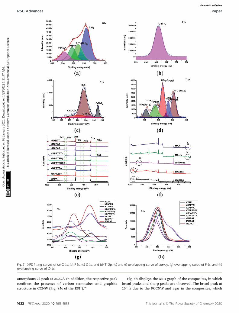
Fig. 7 XPS fitting curves of (a) O 1s, (b) F 1s, (c) C 1s, and (d) Ti 2p, (e) and (f) overlapping curve of survey, (g) overlapping curve of F 1s, and (h)overlapping curve of O 1s.
RSC Advances Paper
Ope
n A
cces
s A
rtic
le. P
ublis
hed
on 0
8 Ja
nuar
y 20
20. D
ownl
oade
d on
1/2
5/20
22 1
:31:
47 A
M.
Thi
s ar
ticle
is li
cens
ed u
nder
a C
reat
ive
Com
mon
s A
ttrib
utio
n-N
onC
omm
erci
al 3
.0 U
npor
ted
Lic
ence
.View Article Online
amorphous 2q peak at 25.52�. In addition, the respective peakconrms the presence of carbon nanotubes and graphitestructure in CCNW (Fig. S5c of the ESI†).58
1622 | RSC Adv., 2020, 10, 1613–1633
Fig. 8b displays the XRD graph of the composites, in whichbroad peaks and sharp peaks are observed. The broad peak at20� is due to the FCCNW and agar in the composites, which
This journal is © The Royal Society of Chemistry 2020
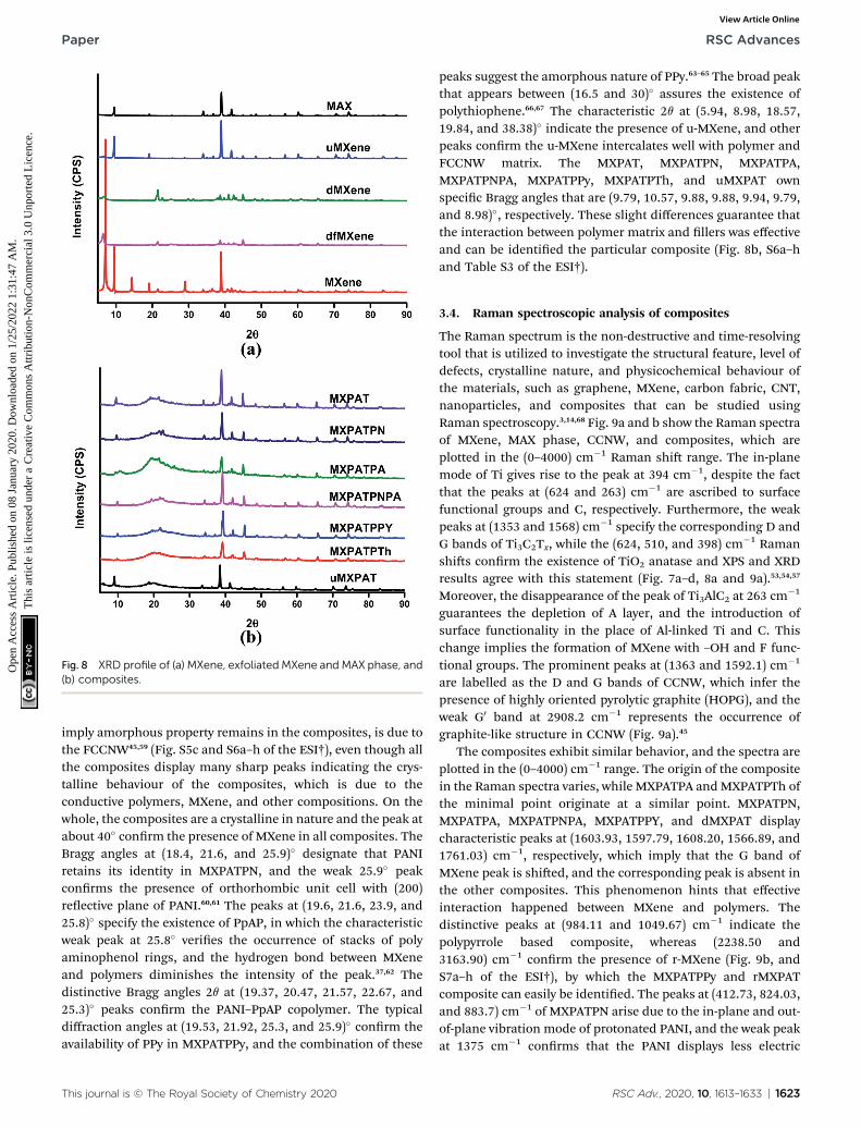
Fig. 8 XRD profile of (a) MXene, exfoliatedMXene and MAX phase, and(b) composites.
Paper RSC Advances
Ope
n A
cces
s A
rtic
le. P
ublis
hed
on 0
8 Ja
nuar
y 20
20. D
ownl
oade
d on
1/2
5/20
22 1
:31:
47 A
M.
Thi
s ar
ticle
is li
cens
ed u
nder
a C
reat
ive
Com
mon
s A
ttrib
utio
n-N
onC
omm
erci
al 3
.0 U
npor
ted
Lic
ence
.View Article Online
imply amorphous property remains in the composites, is due tothe FCCNW45,59 (Fig. S5c and S6a–h of the ESI†), even though allthe composites display many sharp peaks indicating the crys-talline behaviour of the composites, which is due to theconductive polymers, MXene, and other compositions. On thewhole, the composites are a crystalline in nature and the peak atabout 40� conrm the presence of MXene in all composites. TheBragg angles at (18.4, 21.6, and 25.9)� designate that PANIretains its identity in MXPATPN, and the weak 25.9� peakconrms the presence of orthorhombic unit cell with (200)reective plane of PANI.60,61 The peaks at (19.6, 21.6, 23.9, and25.8)� specify the existence of PpAP, in which the characteristicweak peak at 25.8� veries the occurrence of stacks of polyaminophenol rings, and the hydrogen bond between MXeneand polymers diminishes the intensity of the peak.37,62 Thedistinctive Bragg angles 2q at (19.37, 20.47, 21.57, 22.67, and25.3)� peaks conrm the PANI–PpAP copolymer. The typicaldiffraction angles at (19.53, 21.92, 25.3, and 25.9)� conrm theavailability of PPy in MXPATPPy, and the combination of these
This journal is © The Royal Society of Chemistry 2020
peaks suggest the amorphous nature of PPy.63–65 The broad peakthat appears between (16.5 and 30)� assures the existence ofpolythiophene.66,67 The characteristic 2q at (5.94, 8.98, 18.57,19.84, and 38.38)� indicate the presence of u-MXene, and otherpeaks conrm the u-MXene intercalates well with polymer andFCCNW matrix. The MXPAT, MXPATPN, MXPATPA,MXPATPNPA, MXPATPPy, MXPATPTh, and uMXPAT ownspecic Bragg angles that are (9.79, 10.57, 9.88, 9.88, 9.94, 9.79,and 8.98)�, respectively. These slight differences guarantee thatthe interaction between polymer matrix and llers was effectiveand can be identied the particular composite (Fig. 8b, S6a–hand Table S3 of the ESI†).
3.4. Raman spectroscopic analysis of composites
The Raman spectrum is the non-destructive and time-resolvingtool that is utilized to investigate the structural feature, level ofdefects, crystalline nature, and physicochemical behaviour ofthe materials, such as graphene, MXene, carbon fabric, CNT,nanoparticles, and composites that can be studied usingRaman spectroscopy.3,14,68 Fig. 9a and b show the Raman spectraof MXene, MAX phase, CCNW, and composites, which areplotted in the (0–4000) cm�1 Raman shi range. The in-planemode of Ti gives rise to the peak at 394 cm�1, despite the factthat the peaks at (624 and 263) cm�1 are ascribed to surfacefunctional groups and C, respectively. Furthermore, the weakpeaks at (1353 and 1568) cm�1 specify the corresponding D andG bands of Ti3C2Tx, while the (624, 510, and 398) cm�1 Ramanshis conrm the existence of TiO2 anatase and XPS and XRDresults agree with this statement (Fig. 7a–d, 8a and 9a).53,54,57
Moreover, the disappearance of the peak of Ti3AlC2 at 263 cm�1
guarantees the depletion of A layer, and the introduction ofsurface functionality in the place of Al-linked Ti and C. Thischange implies the formation of MXene with –OH and F func-tional groups. The prominent peaks at (1363 and 1592.1) cm�1
are labelled as the D and G bands of CCNW, which infer thepresence of highly oriented pyrolytic graphite (HOPG), and theweak G0 band at 2908.2 cm�1 represents the occurrence ofgraphite-like structure in CCNW (Fig. 9a).45
The composites exhibit similar behavior, and the spectra areplotted in the (0–4000) cm�1 range. The origin of the compositein the Raman spectra varies, while MXPATPA andMXPATPTh ofthe minimal point originate at a similar point. MXPATPN,MXPATPA, MXPATPNPA, MXPATPPY, and dMXPAT displaycharacteristic peaks at (1603.93, 1597.79, 1608.20, 1566.89, and1761.03) cm�1, respectively, which imply that the G band ofMXene peak is shied, and the corresponding peak is absent inthe other composites. This phenomenon hints that effectiveinteraction happened between MXene and polymers. Thedistinctive peaks at (984.11 and 1049.67) cm�1 indicate thepolypyrrole based composite, whereas (2238.50 and3163.90) cm�1 conrm the presence of r-MXene (Fig. 9b, andS7a–h of the ESI†), by which the MXPATPPy and rMXPATcomposite can easily be identied. The peaks at (412.73, 824.03,and 883.7) cm�1 of MXPATPN arise due to the in-plane and out-of-plane vibration mode of protonated PANI, and the weak peakat 1375 cm�1 conrms that the PANI displays less electric
RSC Adv., 2020, 10, 1613–1633 | 1623
Fig. 9 Raman spectroscopy of (a) composite, and (b) MXene, MAXphase, and composite.
RSC Advances Paper
Ope
n A
cces
s A
rtic
le. P
ublis
hed
on 0
8 Ja
nuar
y 20
20. D
ownl
oade
d on
1/2
5/20
22 1
:31:
47 A
M.
Thi
s ar
ticle
is li
cens
ed u
nder
a C
reat
ive
Com
mon
s A
ttrib
utio
n-N
onC
omm
erci
al 3
.0 U
npor
ted
Lic
ence
.View Article Online
conductivity (Fig. 9b, S7c and d of the ESI†).69 The band in the1602.49 cm�1 region engrains the stretching frequency of theC–C bond of PANI.70 In addition, the peaks in the range (800–1000) cm�1, such as (824.03 and 883.7) cm�1, affirm the pres-ence of agar.71 The band at 1135.95 cm�1 can represent thestretching mode of bonds such as C–O and C–C of PVA. Thepeaks at (1179.66 and 1431.69) cm�1 represent the stretchingfrequency of –C–H and –OH of PVA (Fig. 9b, and S7a–h of theESI).72 According to Kumar et al., the trimesic acid can beconrmed by characteristic peaks at 1648 cm�1(C]O),955 cm�1 (–OH–vibration) and 3085 cm�1 (–OH-stretching). Thepeak of C]O at 1651.9 cm�1 conrms the existence of trimesicacid, and the absence of the other two peaks shows that thetrimesic acid bonds successfully with PVA and agar (Fig. 9b andS7c–e†).73 In addition, the weak peaks of CCNW and MXenevirtually disappear, which species that effective interaction hasoccurred among MXene, PANI, agar, PVA, and the othercompositions (Fig. 9b, S7b–h and Table S4 of the ESI†). TheMXPATPNPA overlaps with MXPATPN in about the 60 cm�1
range, while MXPATPA aligns in parallel up to 1000 cm�1, whichdesignates the presence of PANI–PpAP (Fig. 9b, and S7c of the
1624 | RSC Adv., 2020, 10, 1613–1633
ESI†). MXPATPN shows characteristic peaks within 1000 cm�1,and the MXPATPA also exhibits similar peaks at (419.35, 571.25,and 798.92) cm�1, even though MXPATPNPA do not revealtypical peaks in this region, but disclose distinctive peaks at1341.16 cm�1. Further, the distinguishing peaks at1603.93 cm�1 conrm the presence of MXPATPN, MXPATPA,and MXPATPNPA (Fig. 9b, and S7b–d†). The MXPATPPyengenders distinctive bands at (924.8, 984.11, 1049.67, and1566.89) cm�1, in which (924.8, 984.11, and 1049.67) cm�1 areconsidered as the ring deformation of quinoid polaronic,bipolaronic structure, and C–H in-plane deformation of pyrrole,respectively. The peaks at (701.24 and 1450.06) cm�1 conrmthe C–C and C]C stretching frequency of MXPATPTh.74,75 Therange of (250–1500) cm�1 of MXPAT, rMXPAT, dMXPAT, anduMXPAT exposes a linear trend, and exhibits distinctive peaksat (2225.06, 2228.48, 1761.03, and 2114.83) cm�1, by which thecorresponding composites can be identied (Fig. 9b and S7†).Furthermore, the disappearance of the D and G bands of MXeneand CCNW indicates that operative bonding and interactionhave occurred between them, and formed perfect composite.
3.5. Thermal and electric property of the composites
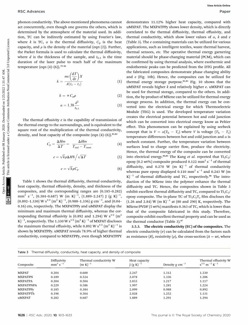
3.5.1. Thermal stability and thermo gravimetric analysis ofcomposites. The thermogravimetry analysis (TGA) and differ-ential thermal analysis (DTA) were exploited to examine thethermal stability of the composite under a particular tempera-ture range. The TGA and DTA analyses were carried out usingAl2O3 crucible in a nitrogen environment (ow rate of 50mL min�1) with a heating rate of 10 �C min�1. Fig. 11a andb show the TGA and DTG graphs, and all the composites displaysimilar behaviour in both cases, with outstanding thermalstability. It was obvious that the weight loss of the compositevaries, due to the constitutional composition effect ofcomposites. The DTG plot displays several peaks that correlatewith the endothermic and exothermic peaks of DSC, where theweight loss of the composite happens.76 The compositeundergoes about 15% weight loss in the temperature range (30–175) �C. Even though the level of weight loss varies according tothe constitutional components of the composites, MXPAT,MXPATPN, MXPATPNPA, MXPATPPy, MXPATPTh and uMXPATlose (16.81, 14.71, 13.37, 13.86, 14.33, 13.65, and 13.69) % ofweight, respectively, and the corresponding temperatures are(194.17, 194.81, 190.77, 194.17, 180.14, 176.52, and 185.45) �C,respectively. The total reductions of weight of MXPAT,MXPATPN, MXPATPNPA, MXPATPPy, MXPATPTh, and uMXPATare (65.69, 58.86, 56.67, 55.09, 66.11, 63.54, and 59.05) %,respectively, in the entire temperature range of (30–1000) �C(Fig. 11a and b, and S8a–h and Table S5 of the ESI†). Among allthe composites, MXPATPPy shows a maximum of 66.11% ofweight loss, while MXPATPNPA shows a minimum of 55.09%.The PANI–PpAP co-polymer minimizes the thermal degrada-tion, which is due to the hydroxyl and amine groups in polymer.On the other hand, the PPy also shows that nitrogen displaysthe highest degradation. Thus, these prominent differences aredue to the copolymer effect. In addition, the thermal stability ofthe composite can also be explained by using heat-resistance
This journal is © The Royal Society of Chemistry 2020
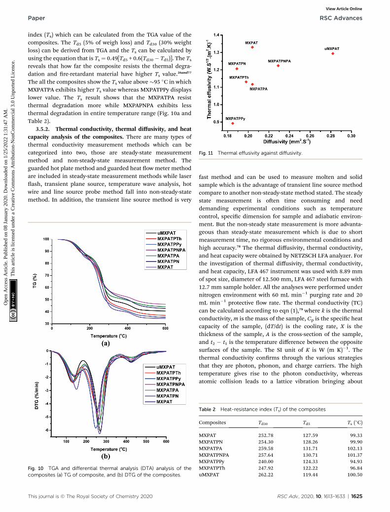
Fig. 11 Thermal effusivity against diffusivity.
Paper RSC Advances
Ope
n A
cces
s A
rtic
le. P
ublis
hed
on 0
8 Ja
nuar
y 20
20. D
ownl
oade
d on
1/2
5/20
22 1
:31:
47 A
M.
Thi
s ar
ticle
is li
cens
ed u
nder
a C
reat
ive
Com
mon
s A
ttrib
utio
n-N
onC
omm
erci
al 3
.0 U
npor
ted
Lic
ence
.View Article Online
index (Ts) which can be calculated from the TGA value of thecomposites. The Td5 (5% of weigh loss) and Td30 (30% weightloss) can be derived from TGA and the Ts can be calculated byusing the equation that is Ts¼ 0.49[Td5 + 0.6(Td30� Td5)]. The Tsreveals that how far the composite resists the thermal degra-dation and re-retardant material have higher Ts value.26and77
The all the composites show the Ts value above �95 �C in whichMXPATPA exhibits higher Ts value whereas MXPATPPy displayslower value. The Ts result shows that the MXPATPA resistthermal degradation more while MXPAPNPA exhibits lessthermal degradation in entire temperature range (Fig. 10a andTable 2).
3.5.2. Thermal conductivity, thermal diffusivity, and heatcapacity analysis of the composites. There are many types ofthermal conductivity measurement methods which can becategorized into two, those are steady-state measurementmethod and non-steady-state measurement method. Theguarded hot plate method and guarded heat ow meter methodare included in steady-state measurement methods while laserash, transient plane source, temperature wave analysis, hotwire and line source probe method fall into non-steady-statemethod. In addition, the transient line source method is very
Fig. 10 TGA and differential thermal analysis (DTA) analysis of thecomposites (a) TG of composite, and (b) DTG of the composites.
This journal is © The Royal Society of Chemistry 2020
fast method and can be used to measure molten and solidsample which is the advantage of transient line source methodcompare to another non-steady-state method stated. The steadystate measurement is oen time consuming and needdemanding experimental conditions such as temperaturecontrol, specic dimension for sample and adiabatic environ-ment. But the non-steady state measurement is more advanta-geous than steady-state measurement which is due to shortmeasurement time, no rigorous environmental conditions andhigh accuracy.78 The thermal diffusivity, thermal conductivity,and heat capacity were obtained by NETZSCH LFA analyzer. Forthe investigation of thermal diffusivity, thermal conductivity,and heat capacity, LFA 467 instrument was used with 8.89 mmof spot size, diameter of 12.500 mm, LFA 467 steel furnace with12.7 mm sample holder. All the analyses were performed undernitrogen environment with 60 mL min�1 purging rate and 20mL min�1 protective ow rate. The thermal conductivity (TC)can be calculated according to eqn (1),79 where k is the thermalconductivity,m is the mass of the sample, Cp is the specic heatcapacity of the sample, (dT/dt) is the cooling rate, X is thethickness of the sample, A is the cross-section of the sample,and t2 � t1 is the temperature difference between the oppositesurfaces of the sample. The SI unit of K is W (m K)�1. Thethermal conductivity conrms through the various strategiesthat they are photon, phonon, and charge carriers. The hightemperature gives rise to the photon conductivity, whereasatomic collision leads to a lattice vibration bringing about
Table 2 Heat-resistance index (Ts) of the composites
Composites Td30 Td5 Ts (�C)
MXPAT 252.78 127.59 99.33MXPATPN 254.30 128.26 99.90MXPATPA 259.58 131.71 102.13MXPATPNPA 257.64 130.71 101.37MXPATPPy 240.00 124.33 94.93MXPATPTh 247.92 122.22 96.84uMXPAT 262.22 119.44 100.50
RSC Adv., 2020, 10, 1613–1633 | 1625
RSC Advances Paper
Ope
n A
cces
s A
rtic
le. P
ublis
hed
on 0
8 Ja
nuar
y 20
20. D
ownl
oade
d on
1/2
5/20
22 1
:31:
47 A
M.
Thi
s ar
ticle
is li
cens
ed u
nder
a C
reat
ive
Com
mon
s A
ttrib
utio
n-N
onC
omm
erci
al 3
.0 U
npor
ted
Lic
ence
.View Article Online
phonon conductivity. The above-mentioned phenomena cannotact concurrently, even though one governs the others, which isdetermined by the atmosphere of the material used. In addi-tion, TC can be indirectly estimated by using Fourier's law,where k is TC, a is the thermal diffusivity, Cp is the heatcapacity, and r is the density of the material (eqn (2)). Further,the Parker formula is used to calculate the thermal diffusivity,where d is the thickness of the sample, and t0.5 is the timeduration of the laser pulse to reach half of the maximumtemperature (eqn (4)–(6)).79–81
k ¼mc
�dT
dt
�X
Aðt2 � t1Þ (1)
k ¼ fCpr (2)
a ¼ 1:38d2
t0:5(3)
The thermal effusivity e is the capability of transmission ofthe thermal energy to the surroundings, and is equivalent to thesquare root of the multiplication of the thermal conductivity,density, and heat capacity of the composite (eqn (4)–(6)).81,82
Cp ¼ DHm
DT¼ DHm
Tend � Tonset
(4)
e ¼ffiffiffik
prDH8
. ffiffiffiffiffiffiffiDT
p(5)
e ¼ffiffiffik
prCp (6)
Table 1 shows the thermal diffusivity, thermal conductivity,heat capacity, thermal effusivity, density, and thickness of thecomposites, and the corresponding ranges are (0.185–0.282)mm2 s�1, (0.384–0.687) W (m K)�1, (1.889–2.247) J (g K)�1,(0.892–1.330) W s1/2 (m2 K)�1, (0.988–1.336) g cm�3, and (0.04–0.16) cm, respectively. The MXPATPPy and uMXPAT display theminimum and maximum thermal diffusivity, whereas the cor-responding thermal effusivity is (0.892 and 1.294) W s1/2 (m2
K)�1, respectively. The 1.330 W s1/2 (m2 K)�1 of MXPAT disclosesthe maximum thermal effusivity, while 0.892 W s1/2 (m2 K)�1 isshown by MXPATPPy. uMXPAT reveals 78.9% of higher thermalconductivity, compared to MXPATPPy, even though MXPATPPY
Table 3 Thermal diffusivity, conductivity, heat capacity, and density of c
CompositeDiffusivitymm2 s�1
Thermal conductivity W(m K)�1
MXPAT 0.204 0.600MXPATPN 0.189 0.524MXPATPA 0.204 0.504MXPATPNPA 0.229 0.586MXPATPPy 0.185 0.384MXPATPTh 0.198 0.504uMXPAT 0.282 0.687
1626 | RSC Adv., 2020, 10, 1613–1633
demonstrates 11.12% higher heat capacity, compared withuMXPAT. The MXPATPPy shows lower density, which is directlycorrelated to the thermal diffusivity, thermal effusivity, andthermal conductivity, which show lower values of a, k and e(Table 3). The e containing materials can be utilized for variousapplications, such as intelligent textiles, waste thermal harvest,thermal sensors, etc. The operative thermal energy garneringmaterial should be phase-changing material (PCM), which canbe conrmed by using thermal analysis, where exothermic andendothermic peaks can be predicted from the DTG prole. Allthe fabricated composites demonstrate phase changing abilityand e (Fig. 10b). Hence, the composites can be utilized forthermal energy storage purpose.81,83 Fig. 10 shows that theuMXPAT reveals higher k and relatively higher e. uMXPAT canbe used for thermal storage, compared to the others. In addi-tion, the by-product of MXene can be utilized for thermal energystorage process. In addition, the thermal energy can be con-verted into the electrical energy for which ThermoelectricModule (TEG) is used. The developed temperature variationcreates the electrical potential between hot and cold junctionwhich can be converted into electrical energy know as Peltiereffect. This phenomenon can be explained by using seebeckconcept that is V ¼ a(Th � Tc) where V is voltage (Th � Tc)temperature differences between hot and cold junction and a isseebeck constant. Further, the temperature variation betweensurfaces lead to charge carrier ow, produce the electricity.Hence, the thermal energy of the composite can be convertedinto electrical energy.84,85 The Kang et al. reported that Ti3C2/epoxy (0.2 wt%) composite produced 0.122 mm2 s�1 of thermaldiffusivity, and 0.270 W (m K)�1 of thermal conductivitywhereas pure epoxy displayed 0.110 mm2 s�1 and 0.243 W (mK)�1 of thermal diffusivity and TC, respectively.86 The intro-duction of the MXene into the polymer enhance the thermaldiffusivity and TC. Hence, the composites shown in Table 3exhibit excellent thermal diffusivity and TC, compared to Ti3C2/epoxy composite. The in-plane TC of Ti3C2Tx lm discloses the(1.26 and 2.84) W (m K)�1 at (80 and 290) K, respectively. TheMXene/PVDF (5 wt%)manifests 0.363 of TC, which is lower thanthat of the composite fabricated in this study. Therefore,composite exhibit excellent thermal property and can be used asthe thermal conductor (Table 3).87
3.5.3. The electric conductivity (EC) of the composites. Theelectric conductivity (s) can be calculated from the factors suchas resistance (R), resistivity (r), the cross-section (A ¼ wt, where
omposite
Heat capacityJ (g K)�1 Density g cm�3
Thermal effusivity Ws1/2 m�2 K�1
2.247 1.312 1.3302.078 1.336 1.2062.033 1.217 1.1171.997 1.281 1.2242.099 0.988 0.8922.028 1.252 1.1311.889 1.291 1.294
This journal is © The Royal Society of Chemistry 2020
Paper RSC Advances
Ope
n A
cces
s A
rtic
le. P
ublis
hed
on 0
8 Ja
nuar
y 20
20. D
ownl
oade
d on
1/2
5/20
22 1
:31:
47 A
M.
Thi
s ar
ticle
is li
cens
ed u
nder
a C
reat
ive
Com
mon
s A
ttrib
utio
n-N
onC
omm
erci
al 3
.0 U
npor
ted
Lic
ence
.View Article Online
w is width and t, is thickness), length (L) and sheet resistance(Rs). The arithmetic multiplication of resistivity and lengthdivided by cross-section gives rise resistance (R¼ (rL)/A) of thematerials. The multiplied value of Rs and t produce the r. Theconductivity of the material is reversibly proposal to r of thematerial.45 The thickness, electric conductivity, surface resis-tance and resistivity of the composites are shown in Table 4. Therange of the thickness of the composites is 0.4–1.6 mm whichindicates the thickness of the composite in mm range. Thecomposites display 1.6–160 000 U and 0.128–256 000 U cmrange of surface resistance and resistivity, respectively. Theconductivity range of the composites place between 3.906 �10�5 and 7.813 S cm�1. It was obvious that MXPATPPY showedvery higher resistance and resistivity compare to othercomposites and exhibites very low EC value of 3.906 �10�5 S cm�1. Hence, the EMI shielding of the MXPATPPy mustbe very low, though, it shows 99.99% of shielding efficiencywhich is discussed in details in Section 3.6. In addition, theMXPATPPy exhibited low thermal diffusivity (0.185 mm2 s�1),thermal conductivity (0.384 W (m K)�1), density (0.988 g cm�3)and thermal effusivity (0.892 W s1/2 m�2 K�1) which indicatesthat the lower EC and its structure inuence the thermalproperties of the MXPATPPy (Tables 3 and 4, Fig. 5d, S1d andS2d†). The internal channels in the composite and surfacecavities play a major role for the uncommon behavior of thecomposite. EC of PVA is 1.63 � 10�12 S cm�1 and the EC of agaris 6.5 � 10�5 S cm�1 which imply that the addition of CP andMXene greatly improve the EC of the composites.88,89 Moreover,the EC of PANI,36 PTh90 and PPy91 are 4.4, 7.17 � 10�6 and0.61 S cm�1, respectively, and change in EC of the compositedue to the presence of the MXene. The conductivity ofMXPATPN and MXPATPA was lower than that of MXPAT, eventhough, MXPATPNPA exhibited 1000 times higher conductivitythan MXPATPN which was due to the introduction of PNPA co-polymer. Thus, PANI–PpAP copolymer have excellent conduc-tivity and EMI shielding enhancing ability than PANI and PpAP(Table 4 and Section 3.6). The above mention phenomenahappened due to the effective hole–electron transportationbetween MXene and PANI–PpAP. It is obvious that CPcomparatively increase the EMI shielding of the composites(Section 3.6). The r-MXene and u-MXene composition heldlower EC compare to MXene which is considered due to lack of
Table 4 The electric conductivity comparison of the composites
CompositesThickness(cm)
Surface resista(Rs U)
MXPAT 0.052 6.1MXPATPN 0.087 15MXPATPA 0.062 13MXPATPNPA 0.08 1.6MXPATPPy 0.16 160 000MXPATPTh 0.092 680uMXPAT 0.04 270dMXPAT 0.06 46rMXPAT 0.066 20
This journal is © The Royal Society of Chemistry 2020
proper orientation and bonding among constitutionalelements, though, rMXPAT possessed 8.18 times higherconductivity than u-MXene. This is due to the availability ofsurface functional groups which promote bonding of llers. Thereduction process considerably replaced –F by –H inMXene andu-MXene signicantly lost surface functional groups due to theexfoliation process. This process diminishes the charge owalong the matrix of the composite, thus, show lower (Table 4).
3.6. EMI shielding measurement
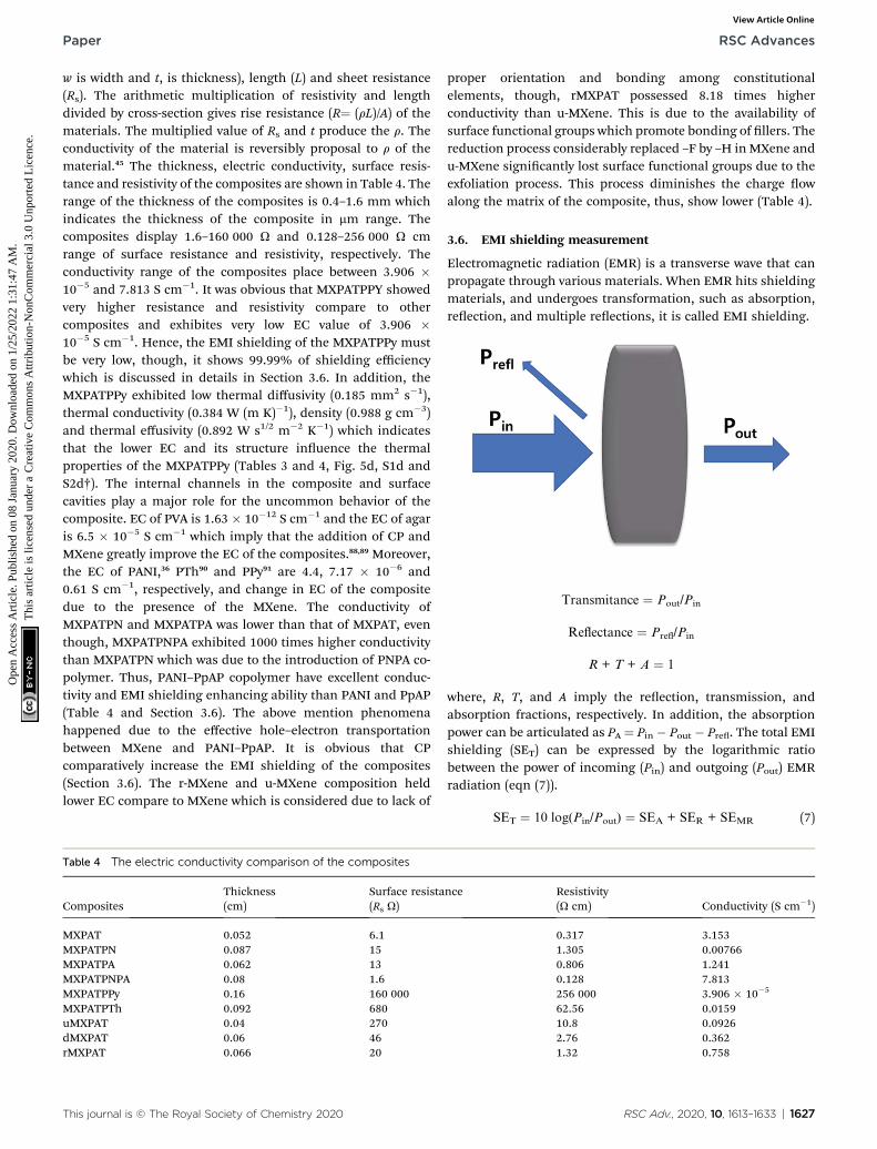
Electromagnetic radiation (EMR) is a transverse wave that canpropagate through various materials. When EMR hits shieldingmaterials, and undergoes transformation, such as absorption,reection, and multiple reections, it is called EMI shielding.
Transmitance ¼ Pout/Pin
Reflectance ¼ Prefl/Pin
R + T + A ¼ 1
where, R, T, and A imply the reection, transmission, andabsorption fractions, respectively. In addition, the absorptionpower can be articulated as PA ¼ Pin � Pout � Pre. The total EMIshielding (SET) can be expressed by the logarithmic ratiobetween the power of incoming (Pin) and outgoing (Pout) EMRradiation (eqn (7)).
SET ¼ 10 log(Pin/Pout) ¼ SEA + SER + SEMR (7)
nce Resistivity(U cm) Conductivity (S cm�1)
0.317 3.1531.305 0.007660.806 1.2410.128 7.813256 000 3.906 � 10�5
62.56 0.015910.8 0.09262.76 0.3621.32 0.758
RSC Adv., 2020, 10, 1613–1633 | 1627
RSC Advances Paper
Ope
n A
cces
s A
rtic
le. P
ublis
hed
on 0
8 Ja
nuar
y 20
20. D
ownl
oade
d on
1/2
5/20
22 1
:31:
47 A
M.
Thi
s ar
ticle
is li
cens
ed u
nder
a C
reat
ive
Com
mon
s A
ttrib
utio
n-N
onC
omm
erci
al 3
.0 U
npor
ted
Lic
ence
.View Article Online
where, SET is the total EMI shielding, SEA is the absorption, SERis the reection, and SEMR is multiple reections. The effect ofmultiple reections is insignicant, and the total EMI shieldingcan be expressed as SET ¼ SEA + SER. Further, the power of theincident wave (PI) can be calculated by adding the reectedpower (PR), absorbed power (PA), and transmitted power (PT)that is PI ¼ PA + PR + PT. In addition, the intensity can becalculated in the same way as Io ¼ IA + IR + IT. The specicshielding effectiveness (SSE) is driven from the ratio betweenEMI SE and density (r) of the materials, and the correspondingunit is dB g�1 cm3. It is obvious that low-density materialspossess higher SSE value. Furthermore, SSE does not have thethickness (t) basis information, because of the large t with lowerr exhibits higher SSE. Hence, absolute effectiveness (SSE/t) withthe unit of dB g�1 cm2 is used to evaluate the thickness effect ofthe material (eqn (8) and (9)).
SSE ¼ EMI SE
r(8)
SSE=t ¼ SSE
t(9)
The composites were fabricated by the spray coating processfor which special polymer composition was synthesized, calledPAT solution. The MXene was directly dispersed in PAT solu-tion, while the conductive polymer was dispersed in NMPsolution. Then both are mixed together, and nally utilized forthe spray coating process on CCNW with areal density of 30 gm�2. In the PAT solution preparation process PVDF used asa plasticizer,92 the trimesic acid is utilized to connect both agarand PVA for the desired FeCl3 used as coupling reagent.93 Theglycerin and polyacrylic acid were exploited as a dispersant andgained the strength of composite, respectively.94,95 The PAT ishydrophilic in nature, as it consists of agar and PVA. This PATsolution was a key player to disseminate MXene evenly, andconductive polymers intercalate within MXene, which createsa conductive network. In addition to the conductive network, CPplays a major role in creating the different structural featureswithin the composite. It is virtually true according to the SEMthat reection (SER) and absorption (SEA) give rise to newphenomena for EMI shielding. In the EMI shielding, theabsorption plays a major role, while reection exposes a generaltrend (Fig. 11a–c and Table S7 of ESI†). The maximum,minimum, and average SE ranges of composite are ((39.33–45.18), (36.04–41.54), and (37.25–42.40)) dB, while themaximum, minimum, and average SER ranges are ((4.71–11.44),(2.27–9.47), and (3.24–10.13)) dB, respectively. In addition, theSEA is prominent compared to SER, and its maximum,minimum, and average ranges are ((29.99–37.57), (26.24–36.46),and (27.55–36.77)) dB, respectively. The maximum EMI shield-ing values of MXPAT, MXPATPN, MXPATPA, MXPATPNPA,MXPATPPy, MXPATPTh, uMXPAT, dMXPAT, and rMXPAT are(41.31, 39.33, 45.18, 44.08, 41.31, 42.99, 39.69, 43.74, and 44.31)dB, respectively; and the corresponding minimum EMI shield-ing values are (38.55, 37.83, 39.00, 37.87, 39.65, 40.25, 36.04,41.54, and 39.94) dB, respectively. In these results, MXPATPA
1628 | RSC Adv., 2020, 10, 1613–1633
shows 45.18 dB of maximum shielding, whereas MXPATPNdisplays 39.33 dB of lowest EMI shielding which is due to theless conductive PANI. The minimum SER values of MXPAT,MXPATPN, MXPATPA, MXPATPNPA, MXPATPPy, MXPATPTh,uMXPAT, dMXPAT, and rMXPAT are (9.27, 7.40, 8.41, 7.37, 2.27,7.87, 9.18, 8.49, and 9.47) dB, respectively, while the corre-sponding maximum SEA values are (30.58, 30.44, 34.85, 36.56,37.57, 34.87, 29.99, 34.48 and 34.09) dB, respectively. It wasfound that MXPATPA exhibits the higher SE of 45.18 dB, whichis due to the PpAP, and the absence of PpAP reduces SE to about10.94%. Hence, the intercalation of CP relatively alters the SEwith respect to MXPAT. MXPATPNPA, MXPATPPy, MXPATPTh,and MXPATPN reveal (6.71, 0, 4.07, and �4.79) %, respectively,where a minus sign indicates the reduction of SE with respect toMXPAT. The reduction of SE in MXPATPN due to PANI can befurther affirmed by the Raman band at 1375 cm�1 (Fig. 9b). It isapparent that the reduction of MXene increases SE by 7.26%which is another output that MXene can be reduced by LiAlH4,and has an impact on EMI shielding (Fig. 11a, and Table S7 ofthe ESI†). The MXPATPPy has ant farm-like structure, whichpromotes the absorption, and surface cavities can be seen bythe naked eye. Fig. 11d below shows the basic mechanism ofMXPATPPy, where surface cavities act as reection, multiplereections, and absorption units, while MXene layerscontribute as multiple reection units, which lead to absorp-tion, and each ant farm-like structure purely gives rise toabsorption unit by internal multiple reection process (Fig. 5d,S1e and S2e of ESI†). Hence, MXPATPPy demonstrates 23.14times higher absorption compared to reection. The MXPAT-PAPN shows 36.56 dB of absorption and 9.09 dB of reectionwhich is due to the porous conductive network of the MXPAT-PAPN. In addition, the MXPATPNPA displays higher EC of7.813 S cm�1 which is due to the presence of PpAP-PANI co-polymer, has impact on reection process. In porous struc-ture, PpAP-PANI co-polymer induces the reection and it turn tomultiple reection in pores which leads to absorption. Thebasic mechanism is similar to the MXPATPPY (Fig. 12a–d andS2d, Table 4, S8 and S9 of the ESI†). The dMXPAT and rMXPATwere studied to compare EMI shielding with MXPAT, in whichrMXPAT shows higher EMI shielding of 44.31 dB, while MXPATshows 41.31 dB with higher mechanical strength (2.88MPa) andelastic nature compare to other composite fabricated (Fig. S9†).Tensile strength of MXene is 1.8 MPa while MXene/eggshellmembrane composite shows 1.48 MPa of tensile strengthwhich is less than that of MXPAT (2.88 MPa) and MXene.96 Inaddition, the tensile strength of MXPATPPy and MXPATPN are1.68 and 1.47 MPa, respectively, and tensile strength ofMXPATPA is 4.3 MPa. The Nacre-Inspired Structure of MXene/cellulose composite displays 135.4 MPa of tensile strength.Hence, addition of PAT composition, arrangement of MXeneake in composite and presence of hydroxyl functional group inpolymer signicantly increase tensile strength of the compos-ites.11,96,97 The SSE range is (28.85–40.49) dB g�1 cm3, in whichuMXPAT demonstrates the lowest value of 28.85 dB g�1 cm3.The SSE/t range was 236.45–721.25 dB g�1 cm2 in which uMX-PAT possessed maximum value of 721.25 dB g�1 cm2 (TableS7†).
This journal is © The Royal Society of Chemistry 2020
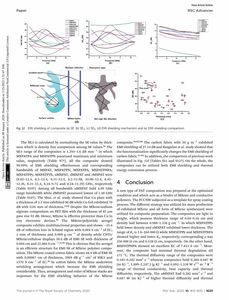
Fig. 12 EMI shielding of composite (a) SE, (b) SEA, (c) SER, (d) EMI shielding mechanism and (e) EMI shielding comparison.
Paper RSC Advances
Ope
n A
cces
s A
rtic
le. P
ublis
hed
on 0
8 Ja
nuar
y 20
20. D
ownl
oade
d on
1/2
5/20
22 1
:31:
47 A
M.
Thi
s ar
ticle
is li
cens
ed u
nder
a C
reat
ive
Com
mon
s A
ttrib
utio
n-N
onC
omm
erci
al 3
.0 U
npor
ted
Lic
ence
.View Article Online
The SE/t is calculated by normalizing the SE value by thick-ness which is density free comparison among SE values.95 TheSE/t range of the composites is 1.393–1.6 dB mm�1 in whichMXPATPA and MXPATPN possessed maximum and minimumvalue, respectively (Table S7†). All the composite showed99.99% of EMI shielding effectiveness and correspondingbandwidth of MXPAT, MXPATPN, MXPATPA, MXPATPNPA,MXPATPPy, MXPATPTh, uMXPAT, dMXPAT and rMXPAT were(8.82–12.4, 8.2–12.4, 9.31–12.4, 8.2–11.98, 10.06–12.4, 8.42–12.36, 8.31–12.4, 8.24–9.72 and 8.24–11.19) GHz, respectively(Table S10†). Among all bandwidth uMXPAT held 4.09 GHzrange bandwidth while dMXPAT possessed lowest of 1.48 GHz(Table S10†). The Shui. et al. study showed that Cu plate witha thickness of 3.1 mm exhibited 90 dB while Cu foil exhibited 70dB with 0.01 mm of thickness.14,98 Despite the MXene/sodiumalginate composition on PET lm with the thickness of 45 mmgave rise 92 dB. Hence, MXene is effective protector than Cu intiny electronic devises.98 The MXene/polyimide aerogelcomposite exhibits multifunctional properties and shows�45.4dB of reection loss in X-band region with 0.004 S cm�1 of EC,2 mm of thickness and 0.009 g cm�3 of density while CNTs/MXene/cellulose displays 38.4 dB of EMI SE with thickness of0.004 cm and 25.066 S cm�1.95,99 This is obvious that the aerogelis an efficient structure for EMI SE of MXene polymer compo-sition. The MXene coated cotton fabric shows 48.9 dB of EMI SEwith 0.00067 cm of thickness, 2969 dB g�1 cm2 of SSE/t and1570 S cm�1 of EC.99 In cotton fabric the MXene underwentwrinkling arrangement which increase the EMI shieldingconsiderably. Thus, arrangement and order of MXene stacks areimportant for the EMI shielding behavior of the MXene
This journal is © The Royal Society of Chemistry 2020
composite.95,99,100 The carbon fabric with 30 g m�2 exhibitedEMI shielding of 27.14 dB and Raagulan et al. study showed thatthe functionalization signicantly changes the EMI shielding ofcarbon fabric.45,101 In addition, the comparison of previous workillustrated in Fig. 11f (Tables S11 and S12†). On the whole, thecomposites can be utilized both EMI shielding and thermalenergy conversion process.
4 Conclusion
A new type of PAT composition was prepared at the optimizedcondition and which acts as a binder of MXene and conductivepolymers. The FCCNW subjected as a template for spray coatingprocess. The different strategy was utilized for mass productionof exfoliated MXene and all form of MXene synthesized wereutilized for composite preparation. The composites are light inweight, which possess thickness range of 0.04–0.16 cm anddensity laid between 0.988–1.336 g cm�1. In which MXPATPPyheld lower density and uMXPAT exhibited lower thickness. Therange of Rs is 1.6–160 000 U while MXPATPPy and MXPATPNPAshowed higher and lower Rs, respectively; corresponding r was256 000 U cm and 0.128 U cm, respectively. On the other hand,MXPATPNPA showed an excellent EC of 7.813 S cm�1. More-over, the composite had minimal thermal degradation till175 �C. The thermal diffusivity range of the composites were0.185–0.282 mm2 s�1 whereas composites hold 0.384–0.687 W(m K)�1, 1.889–2.247 J (g K)�1 and 0.892–1.330 W s1/2 m�2 K�1
range of thermal conductivity, heat capacity and thermaldiffusivity, respectively. The uMXPAT had 0.282 mm2 s�1 and0.687 W (m K)�1 of higher thermal diffusivity and thermal
RSC Adv., 2020, 10, 1613–1633 | 1629
RSC Advances Paper
Ope
n A
cces
s A
rtic
le. P
ublis
hed
on 0
8 Ja
nuar
y 20
20. D
ownl
oade
d on
1/2
5/20
22 1
:31:
47 A
M.
Thi
s ar
ticle
is li
cens
ed u
nder
a C
reat
ive
Com
mon
s A
ttrib
utio
n-N
onC
omm
erci
al 3
.0 U
npor
ted
Lic
ence
.View Article Online
conductivity, respectively. While MXPAT showed 2.247 J (g K)�1
and 1.330 W s1/2 m�2 K�1 of heat capacity and thermal effu-sivity, respectively. The MXPATPA exhibited maximum EMIshielding of 45.18 dB (9.31–12.4 GHz) with 33.26 dB g�1 cm3,236.45 dB g�1 cm2 and 1.6 dB mm�1 of SSE, SSE/t and SE/t,respectively. The composites blocked almost 99.99% of incidentradiation and maximum SE range of 45.18–39.33 dB while SSE,SSE/t and SE/t range were 27.99–40.49 dB g�1 cm3, 236.45–721.25 dB g�1 cm2 and 1.393–1.6 dB mm�1, respectively. Thecomposites possess excellent EMI shielding ability, exibilityand good thermal behaviors. Thus, composites can be utilizedfor both thermal and EMI shielding applications.
Conflicts of interest
The authors declare no conict of interest.
Acknowledgements
This work is supported by Wonkwang University in the year of2019.
References
1 Y. J. Yim, D. C. Chung and S. J. Park, EMI shieldingeffectiveness and mechanical properties of MWCNTs-reinforced biodegradable epoxy matrix composites,Carbon Letters, 2017, 22, 36–41.
2 S. Engels, N. L. Schneider, N. Lefeldt, C. M. Hein, M. Zapka,A. Michalik, D. Elbers, A. Kittel, P. J. Hore and H. Mouritsen,Anthropogenic electromagnetic noise disrupts magneticcompass orientation in a migratory bird, Nature, 2014,509(7500), 353.
3 S. Pothupitiya Gamage, K. Yang, R. Braveenth, K. Raagulan,H. Kim, Y. Lee, C. M. Yang, J. Moon and K. Chai, MWCNTcoated free-standing carbon ber fabric for enhancedperformance in EMI shielding with a higher absolute EMISE, Materials, 2017, 10(12), 1350.
4 A. Wdowiak, P. A. Mazurek, A. Wdowiak and I. Bojar, Effectof electromagnetic waves on human reproduction, Ann.Agric. Environ. Med., 2017, 24(1), 13–18.
5 A. Asghari, A. A. Khaki, A. Rajabzadeh and A. Khaki, Areview on Electromagnetic elds (EMFs) and thereproductive system, Electron. Physician, 2016, 8(7), 2655.
6 S. J. Genuis, Fielding a current idea: exploring the publichealth impact of electromagnetic radiation, Public Health,2008, 122(2), 113–124.
7 P. Vecchia, Exposure of humans to electromagnetic elds.Standards and regulations, Ann. Istituto Super. Sanita,2007, 43(3), 260.
8 F. Ozdemir and A. Kargi, Electromagnetic waves and humanhealth, in Electromagnetic Waves, IntechOpen, 2011.
9 P. Russer, Electromagnetic Compatibility Engineering forElectronic Circuits and Devices, in Proceedings of IEEECALCON 2014, National Conference on Electrical,Electronics, and Computer Engineering, Gallery 2 TechnicalSession T4 (EC), 2014.
1630 | RSC Adv., 2020, 10, 1613–1633
10 J. Shapira, Electromagnetic Compatibility for SystemEngineers, IETE Tech. Rev., 2011, 28(1), 70–77.
11 W. T. Cao, F. F. Chen, Y. J. Zhu, Y. G. Zhang, Y. Y. Jiang,M. G. Ma and F. Chen, Binary strengthening andtoughening of MXene/cellulose nanober compositepaper with nacre-inspired structure and superiorelectromagnetic interference shielding properties, ACSNano, 2018, 12(5), 4583–4593.
12 R. Liu, M. Miao, Y. Li, J. Zhang, S. Cao and X. Feng,Ultrathin Biomimetic Polymeric Ti3C2Tx MXeneComposite Films for Electromagnetic InterferenceShielding, ACS Appl. Mater. Interfaces, 2018, 10(51), 44787–44795.
13 Q. W. Wang, H. B. Zhang, J. Liu, S. Zhao, X. Xie, L. Liu,R. Yang, N. Koratkar and Z. Z. Yu, Multifunctional andWater-Resistant MXene-Decorated Polyester Textiles withOutstanding Electromagnetic Interference Shielding andJoule Heating Performances, Adv. Funct. Mater., 2019,29(7), 1806819.
14 F. Shahzad, M. Alhabeb, C. B. Hatter, B. Anasori,S. M. Hong, C. M. Koo and Y. Gogotsi, Electromagneticinterference shielding with 2D transition metal carbides(MXenes), Science, 2016, 353(6304), 1137–1140.
15 S. K. Yee and M. Z. M. Jenu, Electromagnetic Shielding ofCement-Graphite Powder Between 100 to 2000 MHz, ARPNJ. Eng. Appl. Sci., 2015, 1–4.
16 R. Bian, G. He, W. Zhi, S. Xiang, T. Wang and D. Cai,Ultralight MXene-based aerogels with highelectromagnetic interference shielding performance, J.Mater. Chem. C, 2019, 7(3), 474–478.
17 L. W. Shacklette, N. F. Colaneri, V. G. Kulkarni andB. Wessling, EMI shielding of intrinsically conductivepolymers, J. Vinyl Addit. Technol., 1992, 14(2), 118–122.
18 K. Raagulan, R. Braveenth, H. Jang, Y. Seon Lee, C. M. Yang,B. Mi Kim, J. Moon and K. Chai, Electromagnetic shieldingby MXene-graphene-PVDF composite with hydrophobic,lightweight and exible graphene coated fabric, Materials,2018, 11(10), 1803.
19 D. Jiang, V. Murugadoss, Y. Wang, J. Lin, T. Ding, Z. Wang,Q. Shao, C. Wang, H. Liu, N. Lu and R. Wei,Electromagnetic interference shielding polymers andnanocomposites-a review, Polym. Rev., 2019, 59(2), 280–337.
20 L. C. Jia, D. X. Yan, X. Jiang, H. Pang, J. F. Gao, P. G. Ren andZ. M. Li, Synergistic Effect of Graphite and CarbonNanotubes on Improved Electromagnetic InterferenceShielding Performance in Segregated Composites, Ind.Eng. Chem. Res., 2018, 57(35), 11929–11938.
21 T. T. Li, A. P. Chen, P. W. Hwang, Y. J. Pan, W. H. Hsing,C. W. Lou, Y. S. Chen and J. H. Lin, Synergistic effects ofmicro-/nano-llers on conductive and electromagneticshielding properties of polypropylene nanocomposites,Mater. Manuf. Processes, 2018, 33(2), 149–155.
22 J. A. Pomposo, J. Rodrıguez and H. Grande, Polypyrrole-based conducting hot melt adhesives for EMI shieldingapplications, Synth. Met., 1999, 104(2), 107–111.
23 M. K. Erdogan, M. Karakisla and M. Saçak, Preparation,characterization and electromagnetic shielding
This journal is © The Royal Society of Chemistry 2020
Paper RSC Advances
Ope
n A
cces
s A
rtic
le. P
ublis
hed
on 0
8 Ja
nuar
y 20
20. D
ownl
oade
d on
1/2
5/20
22 1
:31:
47 A
M.
Thi
s ar
ticle
is li
cens
ed u
nder
a C
reat
ive
Com
mon
s A
ttrib
utio
n-N
onC
omm
erci
al 3
.0 U
npor
ted
Lic
ence
.View Article Online
effectiveness of conductive polythiophene/poly(ethyleneterephthalate)composite bers, J. Macromol. Sci., Part A:Pure Appl. Chem., 2012, 49(6), 473–482.
24 J. Liu, H. B. Zhang, R. Sun, Y. Liu, Z. Liu, A. Zhou andZ. Z. Yu, Hydrophobic, exible, and lightweight MXenefoams for high-performance electromagnetic-interferenceshielding, Adv. Mater., 2017, 29(38), 1702367.
25 Z. Zhou, J. Liu, X. Zhang, D. Tian, Z. Zhan and C. Lu,Ultrathin MXene/Calcium Alginate Aerogel Film forHigh-Performance Electromagnetic InterferenceShielding, Adv. Mater. Interfaces, 2019, 6(6), 1802040.
26 X. Yang, S. Fan, Y. Li, Y. Guo, Y. Li, K. Ruan, S. Zhang,J. Zhang, J. Kong and J. Gu, Synchronously improvedelectromagnetic interference shielding and thermalconductivity for epoxy nanocomposites by constructing3D copper nanowires/thermally annealed grapheneaerogel framework, Composites, Part A, 2020, 128, 105670.
27 Y. Zhang, L. Wang, J. Zhang, P. Song, Z. Xiao, C. Liang,H. Qiu, J. Kong and J. Gu, Fabrication and investigationon the ultra-thin and exible Ti3C2Tx/co-dopedpolyaniline electromagnetic interference shieldingcomposite lms, Compos. Sci. Technol., 2019, 183, 107833.
28 A. Tanvir, P. Sobolciak, A. Popelka, M. Mrlik, Z. Spitalsky,M. Micusik, J. Prokes and I. Krupa, Electricallyconductive, transparent polymeric nanocompositesmodied by 2D Ti3C2Tx (MXene), Polymers, 2019, 11(8),1272.
29 K. J. Zhang, D. B. Lu, B. Da and Z. J. Ding, Coupling ofSurface Plasmon Modes and Refractive Index Sensitivityof Hollow Silver Nanoprism, Sci. Rep., 2018, 8(1), 15993.
30 M. Alhabeb, K. Maleski, B. Anasori, P. Lelyukh, L. Clark,S. Sin and Y. Gogotsi, Guidelines for Synthesis andProcessing of Two-Dimensional Titanium Carbide(Ti3C2Tx MXene), Chem. Mater., 2017, 29(18), 7633–7644.
31 J. Luo, W. Zhang, H. Yuan, C. Jin, L. Zhang, H. Huang,C. Liang, Y. Xia, J. Zhang, Y. Gan and X. Tao, Pillaredstructure design of MXene with ultralarge interlayerspacing for high-performance lithium-ion capacitors, ACSNano, 2017, 11(3), 2459–2469.
32 J. Palisaitis, I. Persson, J. Halim, J. Rosen and P. O. Persson,On the structural stability ofMXene and the role of transitionmetal adatoms, Nanoscale, 2018, 10(23), 10850–10855.
33 R. Lot, M. Naguib, D. E. Yilmaz, J. Nanda and A. C. VanDuin, A comparative study on the oxidation of two-dimensional Ti3C2 MXene structures in differentenvironments, J. Mater. Chem. A, 2018, 6(26), 12733–12743.
34 N. Zhang, Y. Hong, S. Yazdanparast and M. A. Zaeem,Superior structural, elastic and electronic properties of 2Dtitanium nitride MXenes over carbide MXenes:a comprehensive rst principles study, 2D Materials, 2018,5(4), 045004.
35 Z. M. Sun, Progress in research and development on MAXphases: a family of layered ternary compounds, Int. Mater.Rev., 2011, 56(3), 143–166.
36 J. Stejskal and R. G. Gilbert, Polyaniline: Preparation ofa conducting polymer (IUPAC technical report), Pure Appl.Chem., 2002, 74(5), 857–867.
This journal is © The Royal Society of Chemistry 2020
37 G. Thenmozhi, P. Arockiasamy and R. J. Santhi, Isomers ofpoly aminophenol: chemical synthesis, characterization,and its corrosion protection aspect on mild steel in 1 MHCl, Int. J. Electrochem., 2014, 2014, 1–11.
38 A. Yussuf, M. Al-Saleh, S. Al-Enezi and G. Abraham,Synthesis and Characterization of Conductive Polypyrrole:The Inuence of the Oxidants and Monomer on theElectrical, Thermal, and Morphological Properties, Int. J.Polym. Sci., 2018, 2018, 1–7.
39 Z. Wang, Y. Wang, D. Xu, E. S. W. Kong and Y. Zhang, Facilesynthesis of dispersible spherical polythiophene nanoparticlesby copper (II) catalyzed oxidative polymerization in aqueousmedium, Synth. Met., 2010, 160(9–10), 921–926.
40 M. Nasrollahzadeh, M. Jahanshahi, M. Salehi, M. Behzadand H. Nasrollahzadeh, Synthesis and characterization ofnanostructured polythiophene in aqueous medium byso-template method, J. Appl. Chem., 2013, 8, 31–34.
41 A. Mockute, Synthesis and Characterization of New MAXPhase Alloys, Doctoral dissertation, Linkoping UniversityElectronic Press, 2014.
42 Y. Tan, H. Luo, X. Zhou, S. Peng and H. Zhang,Dependences of microstructure on electromagneticinterference shielding properties of nano-layered Ti3AlC2
ceramics, Sci. Rep., 2018, 8(1), 7935.43 A. Tariq, M. A. Iqbal, S. I. Ali, M. Z. Iqbal, D. Akinwande and
S. Rizwan, Ti3C2-MXene/Bismuth Ferrite Nanohybrids forEfficient Degradation of Organic Dye and ColorlessPollutant, ChemRxiv, 2019, 1–33.
44 N. K. Chaudhari, H. Jin, B. Kim, D. San Baek, S. H. Joo andK. M. X. Lee, an emerging two-dimensional material forfuture energy conversion and storage applications, J.Mater. Chem. A, 2017, 5(47), 24564–24579.
45 K. Raagulan, R. Braveenth, L. Ro Lee, J. Lee, B. M. Kim,J. J. Moon, S. B. Lee and K. Y. Chai, Fabrication ofFlexible, Lightweight, Magnetic Mushroom Gills andCoral-Like MXene–Carbon Nanotube Nanocomposites forEMI Shielding Application, Nanomaterials, 2019, 9(4), 519.
46 C. Di Franco, E. Beccari, T. Santini, G. Pisaneschi andG. Tecce, Colony shape as a genetic trait in the pattern-forming Bacillus mycoides, BMC Microbiol., 2002, 2(1), 33.
47 S. O. Mast, Structure, movement, locomotion, andstimulation in amoeba, J. Morphol., 1926, 41(2), 347–425.
48 P. Graat and M. A. Somers, Quantitative analysis ofoverlapping XPS peaks by spectrum reconstruction:determination of the thickness and composition of thiniron oxide lms, Surf. Interface Anal., 1998, 26(11), 773–782.
49 T. W. Lee, S. E. Lee and Y. G. Jeong, Carbon nanotube/cellulose papers with high performance in electric heatingand electromagnetic interference shielding, Compos. Sci.Technol., 2016, 131, 77–87.
50 A. Qian, S. E. Hyeon, J. Y. Seo and C. H. Chung, Capacitancechanges associated with cation-transport in free-standingexible Ti3C2Tx(TO,F,OH) MXene lm electrodes,Electrochim. Acta, 2018, 266, 86–93.
51 V. Datsyuk, M. Kalyva, K. Papagelis, J. Parthenios, D. Tasis,A. Siokou, I. Kallitsis and C. Galiotis, Chemical oxidation ofmultiwalled carbon nanotubes, Carbon, 2008, 46, 833–840.
RSC Adv., 2020, 10, 1613–1633 | 1631
RSC Advances Paper
Ope
n A
cces
s A
rtic
le. P
ublis
hed
on 0
8 Ja
nuar
y 20
20. D
ownl
oade
d on
1/2
5/20
22 1
:31:
47 A
M.
Thi
s ar
ticle
is li
cens
ed u
nder
a C
reat
ive
Com
mon
s A
ttrib
utio
n-N
onC
omm
erci
al 3
.0 U
npor
ted
Lic
ence
.View Article Online
52 L. Wang, H. Zhang, B. Wang, C. Shen, C. Zhang, Q. Hu,A. Zhou and B. Liu, Synthesis and electrochemicalperformance of Ti3C2Tx with hydrothermal process,Electron. Mater. Lett., 2016, 12, 702–710.
53 H. B. Zhang, Y. C. Zhou, Y. W. Bao and M. S. Li, Abnormalthermal shock behavior of Ti3SiC2 and Ti3AlC2, J. Mater.Res., 2006, 21, 2401–2407.
54 M. Han, X. Yin, H. Wu, Z. Hou, C. Song, X. Li, L. Zhang andL. Cheng, Ti3C2 MXenes with modied surface for high-performance electromagnetic absorption and shielding inthe X-band, ACS Appl. Mater. Interfaces, 2016, 8, 21011–21019.
55 A. Ivasyshyn, O. Ostash, T. Prikhna, V. Podhurska andT. Basyuk, Oxidation Resistance of Materials Based onTi3AlC2 Nanolaminate at 600 �C in Air, Nanoscale Res.Lett., 2016, 11, 358.
56 T. A. Saleh, S. Agarwal and V. K. Gupta, Synthesis ofMWCNT/MnO2 and their application for simultaneousoxidation of arsenite and sorption of arsenate, Appl.Catal., B, 2011, 106, 46–53.
57 P. Yan, R. Zhang, J. Jia, C. Wu, A. Zhou, J. Xu and X. Zhang,Enhanced supercapacitive performance of delaminatedtwo-dimensional titanium carbide/carbon nanotubecomposites in alkaline electrolyte, J. Power Sources, 2015,284, 38–43.
58 V. Gupta and T. A. Saleh, Syntheses of carbon nanotube-metal oxides composites; adsorption and photo-degradation, in Carbon Nanotubes-From Research toApplications, InTech, Shanghai, China, 2011.
59 R. Leones, F. Sentanin, L. C. Rodrigues, I. M. Marrucho,J. M. S. S. Esperança, A. Pawlicka and M. M. Silva,Investigation of polymer electrolytes based on agar andionic liquids, Express Polym. Lett., 2012, 6(12), 1007–1016.
60 H. Xu, J. Zhang, Y. Chen, H. Lu and J. Zhuang,Electrochemical polymerization of polyaniline doped withCu2+ as the electrode material for electrochemicalsupercapacitors, RSC Adv., 2014, 4(11), 5547–5552.
61 Z. Zhou, X. Zhang, C. Lu, L. Lan and G. Yuan, Polyaniline-decorated cellulose aerogel nanocomposite with stronginterfacial adhesion and enhanced photocatalytic activity,RSC Adv., 2014, 4(18), 8966–8972.
62 H. Duan, K. Zheng, L. Zhang and Y. Cui, Synthesis of poly(4-aminophenol) by horseradish peroxidase and theevaluation of its adsorptivity for silver ions, J. Appl. Polym.Sci., 2014, 131(12), 40367–40373.
63 K. Ahmed, F. Kanwal, S. Ramay, S. Atiq, R. Rehman, S. Aliand N. Alzayed, Synthesis and Characterization of BaTiO3/Polypyrrole Composites with Exceptional DielectricBehaviour, Polymers, 2018, 10(11), 1273.
64 S. Shrikrushna, J. A. Kher and M. V. Kulkarni, Inuence ofdodecylbenzene sulfonic acid doping on structural,morphological, electrical and optical properties onpolypyrrole/3C-SiC nanocomposites, J. Nanomed.Nanotechnol., 2015, 6(5), 1.
65 J. Al Dream, C. Zequine, K. Siam, P. K. Kahol, S. R.Mishra andR. K. Gupta, Electrochemical Properties of Graphene OxideNanoribbons/Polypyrrole Nanocomposites, C, 2019, 5(2), 18.
1632 | RSC Adv., 2020, 10, 1613–1633
66 F. Zhang, Y. Shi, Z. Zhao, W. Song and Y. Cheng, Inuenceof semiconductor/insulator/semiconductor structure onthe photo-catalytic activity of Fe3O4/SiO2/polythiophenecore/shell submicron composite, Appl. Catal., B, 2014,150, 472–478.
67 M. Sharif and B. Pourabas, Polythiophene–graphene oxidedoped epoxy resin nanocomposites with enhancedelectrical, mechanical and thermal properties, RSC Adv.,2016, 6(96), 93680–93693.
68 M. Hu, Z. Li, T. Hu, S. Zhu, C. Zhang and X. Wang, High-Capacitance Mechanism for Ti3CTx MXene by in SituElectrochemical Raman Spectroscopy Investigation, ACSNano, 2016, 10(12), 11344–11350.
69 A. B. Rohom, P. U. Londhe, S. K. Mahapatra, S. K. Kulkarniand N. B. Chaure, Electropolymerization of polyaniline thinlms, High Perform. Polym., 2014, 26(6), 641–646.
70 D. N. Huyen, N. T. Tung, N. D. Thien and L. H. Thanh,Effect of TiO2 on the gas sensing features of TiO2/PANinanocomposites, Sensors, 2011, 11(2), 1924–1931.
71 F. S. de Siqueira Oliveira, H. E. Giana and L. Silveira,Discrimination of selected species of pathogenic bacteriausing near-infrared Raman spectroscopy and principalcomponents analysis, J. Biomed. Opt., 2012, 17(10), 107004.
72 N. A. Zubair, N. A. Rahman, H. N. Lim, R. M. Zawawi andY. Sulaiman, Electrochemical properties of PVA–GO/PEDOT nanobers prepared using electrospinning andelectropolymerization techniques, RSC Adv., 2016, 6(21),17720–17727.
73 K. Kumar and S. Murugesan, Synthesis, characterizationand anti-bacterial activity of divalent transition metalcomplexes of hydrazine and trimesic acid, J. Saudi Chem.Soc., 2018, 22(1), 16–26.
74 C. Yong and Q. Renyuan, IR and Raman studies ofpolythiophene prepared by electrochemicalpolymerization, Solid State Commun., 1985, 54(3), 211–213.
75 X. Fan, Z. Yang and N. He, Hierarchical nanostructuredpolypyrrole/graphene composites as supercapacitorelectrode, RSC Adv., 2015, 5(20), 15096–15102.
76 I. Rashid, N. H. Daraghmeh, M. M. Al Omari,B. Z. Chowdhry, S. A. Leharne, H. A. Hodali andA. A. Badwan, Magnesium silicate, in Proles of DrugSubstances, Excipients and Related Methodology, AcademicPress, 2011, vol. 36, pp. 241–285.
77 M. Haezal, A. Khalina, Z. Zurina, M. Azaman andZ. Hanafee, Thermal and Flammability Characteristics ofBlended Jatropha Bio-Epoxy as Matrix in Carbon Fiber–Reinforced Polymer, J. Compos. Sci., 2019, 3(1), 6.
78 X. Yang, C. Liang, T. Ma, Y. Guo, J. Kong, J. Gu, M. Chen andJ. Zhu, A review on thermally conductive polymericcomposites: classication, measurement, model andequations, mechanism and fabrication methods, Adv.Compos. Hybrid Mater., 2018, 1(2), 207–230.
79 R. Singh, G. Sandhu, R. Penna and I. Farina, Investigationsfor thermal and electrical conductivity of ABS-grapheneblended prototypes, Materials, 2017, 10(8), 881.
80 J. Szałapak, K. Kiełbasinski, J. Krzeminski, A. Młozniak,E. Zwierkowska, M. Jakubowska and R. Pawłowski, A
This journal is © The Royal Society of Chemistry 2020
Paper RSC Advances
Ope
n A
cces
s A
rtic
le. P
ublis
hed
on 0
8 Ja
nuar
y 20
20. D
ownl
oade
d on
1/2
5/20
22 1
:31:
47 A
M.
Thi
s ar
ticle
is li
cens
ed u
nder
a C
reat
ive
Com
mon
s A
ttrib
utio
n-N
onC
omm
erci
al 3
.0 U
npor
ted
Lic
ence
.View Article Online
Method Of Calculating Thermal Diffusivity AndConductivity For Irregularly Shaped Specimens In LaserFlash Analysis, Metrol. Meas. Syst., 2015, 22(4), 521–530.
81 L. Vozar and W. Hohenauer, Flash method of measuringthe thermal diffusivity. A review, High. Temp.–High. Press.,2004, 36(3), 253–264.
82 A. L. Cottrill, A. T. Liu, Y. Kunai, V. B. Koman, A. Kaplan,S. G. Mahajan, P. Liu, A. R. Toland and M. S. Strano,Ultra-high thermal effusivity materials for resonantambient thermal energy harvesting, Nat. Commun., 2018,9(1), 664.
83 H. Lei, C. Fu, Y. Zou, S. Guo and J. Huo, A thermal energystorage composite with sensing function and its thermalconductivity and thermal effusivity enhancement, J.Mater. Chem. A, 2019, 7(12), 6720–6729.
84 H. U. Zaman, C. E. Shourov, A. Al Mahmood andN. E. A. Siddique, Conversion of wasted heat energy intoelectrical energy using TEG, in 2017, IEEE 7th AnnualComputing and Communication Workshop and Conference(CCWC), IEEE., 2017, pp. 1–5.
85 T. Kyono, R. O. Suzuki and K. Ono, Conversion of unusedheat energy to electricity by means of thermoelectricgeneration in condenser, IEEE Trans. Energy Convers.,2003, 18(2), 330–334.
86 R. Kang, Z. Zhang, L. Guo, J. Cui, Y. Chen, X. Hou, B. Wang,C. T. Lin, N. Jiang and J. Yu, Enhanced ThermalConductivity of Epoxy Composites Filled with 2DTransition Metal Carbides (MXenes) with UltralowLoading, Sci. Rep., 2019, 9(1), 9135.
87 Y. Cao, Q. Deng, Z. Liu, D. Shen, T. Wang, Q. Huang, S. Du,N. Jiang, C. T. Lin and J. Yu, Enhanced thermal propertiesof poly(vinylidene uoride) composites with ultrathinnanosheets of MXene, RSC Adv., 2017, 7(33), 20494–20501.
88 S. Ningaraju and H. B. Ravikumar, Studies on electricalconductivity of PVA/graphite oxide nanocomposites: a freevolume approach, J. Polym. Res., 2017, 24(1), 11.
89 T. J. Trivedi, K. S. Rao and A. Kumar, Facile preparation ofagarose–chitosan hybrid materials and nanocompositeionogels using an ionic liquid via dissolution,regeneration and sol–gel transition, Green Chem., 2014,16(1), 320–330.
90 R. Liu and Z. Liu, Polythiophene: synthesis in aqueousmedium and controllable morphology, Chin. Sci. Bull.,2009, 54(12), 2028–2032.
This journal is © The Royal Society of Chemistry 2020
91 J. C. Thieblemont, J. L. Gabelle and M. F. Planche,Polypyrrole overoxidation during its chemical synthesis,Synth. Met., 1994, 66(3), 243–247.
92 C. H. Du, Y. Y. Xu and B. K. Zhu, Plasticizer effect of dibutylphthalate on the morphology and mechanical properties ofhard elastic poly(vinylidene uoride) bers, J. Appl. Polym.Sci., 2009, 114(6), 3645–3651.
93 N. Ieda, K. Mantri, Y. Miyata, A. Ozaki, K. Komura andY. Sugi, Esterication of long-chain acids and alcoholscatalyzed by ferric chloride hexahydrate, Ind. Eng. Chem.Res., 2008, 47(22), 8631–8638.
94 M. Guillot, D. Ruhlmann and M. Buri, Use of glycerol as anagent to improve the self-dispersing properties of a mineralmaterial to be added to an aqueous composition, US Pat.,163147, Omya International AG and Coatex SAS, 2015.
95 J. Liu, H. B. Zhang, X. Xie, R. Yang, Z. Liu, Y. Liu andZ. Z. Yu, Multifunctional, superelastic, and lightweightMXene/polyimide aerogels, Small, 2018, 14(45), 1802479.
96 M. Han, X. Yin, K. Hantanasirisakul, X. Li, A. Iqbal,C. B. Hatter, B. Anasori, C. M. Koo, T. Torita, Y. Soda andL. Zhang, Anisotropic MXene Aerogels witha Mechanically Tunable Ratio of Electromagnetic WaveReection to Absorption, Adv. Opt. Mater., 2019, 7(10),1900267.
97 W. Xin, G. Q. Xi, W. T. Cao, C. Ma, T. Liu, M. G. Ma andJ. Bian, Lightweight and exible MXene/CNF/silvercomposite membranes with a brick-like structure andhigh-performance electromagnetic-interference shielding,RSC Adv., 2019, 9(51), 29636–29644.
98 X. Shui and D. D. L. Chung, Nickel lament polymer-matrixcomposites with low surface impedance and highelectromagnetic interference shielding effectiveness, J.Electron. Mater., 1997, 26, 928–934.
99 W. Cao, C. Ma, S. Tan, M. Ma, P. Wan and F. Chen,Ultrathin and Flexible CNTs/MXene/Cellulose NanobrilsComposite Paper for Electromagnetic InterferenceShielding, Nano-Micro Lett., 2019, 11(1), 72.
100 L. Geng, P. Zhu, Y. Wei, R. Guo, C. Xiang, C. Cui and Y. Li, Afacile approach for coating Ti3C2Tx on cotton fabric forelectromagnetic wave shielding, Cellulose, 2019, 26(4),2833–2847.
101 K. Raagulan, R. Braveenth, H. J. Jang, Y. S. Lee, C. M. Yang,B. M. Kim, J. J. Moon and K. Y. Chai, Fabrication ofNonwetting Flexible Free-Standing MXene-Carbon Fabricfor Electromagnetic Shielding in S-Band Region, Bull.Korean Chem. Soc., 2018, 39(12), 1412–1419.
RSC Adv., 2020, 10, 1613–1633 | 1633