an efficient method for performance monitoring of active
TRANSCRIPT

1236 IEEE TRANSACTIONS ON GEOSCIENCE AND REMOTE SENSING, VOL. 47, NO. 4, APRIL 2009
An Efficient Method for Performance Monitoringof Active Phased Array Antennas
Benjamin Bräutigam, Marco Schwerdt, and Markus Bachmann
Abstract—Modern synthetic aperture radars (SARs) areequipped with active phased array antennas to electronically gen-erate various antenna beams. The TerraSAR-X satellite is a highresolution SAR system launched in June 2007. Its active phasedarray X-band antenna hosts 384 transmit/receive modules (TRMs)for controlling the electronic beam steering in azimuth and eleva-tion direction. The precise modeling of the antenna performanceis only possible if the actual characteristics of each individualTRM are monitored. TerraSAR-X has been equipped with aninnovative characterization mode based on a coding technique,which is the so-called pseudonoise gating method. The individualand simultaneous characterization of all TRMs is realized undermost realistic conditions with power supply loads like in nominalradar operation. For the first time, this novel technique has beenapplied on a spaceborne SAR system.
Index Terms—Active phased array antenna, internal calibra-tion, synthetic aperture radar (SAR), TerraSAR-X, transmit/receive modules (TRMs).
I. INTRODUCTION
THE FAST technological progress and success in remotesensing applications based on spaceborne synthetic aper-
ture radars (SARs) lead to flexible radar systems to satisfythe user needs for global earth observation with diverse dataproducts. Recent satellite SAR instruments are featuring var-ious antenna beams and imaging modes. Many modern SARsystems operate an active phased array antenna to provide themultitude of different antenna beams within short switchingtimes. The accurate monitoring of the antenna performancebecomes necessary to achieve the high stability requirementsof satellite SAR instruments.
The German satellite mission TerraSAR-X, launched in June2007, has been designed as a flexible X-band SAR system im-plemented in a public–private-partnership between the GermanAerospace Center (DLR) and EADS Astrium GmbH [1]. Thesatellite produces high-quality images in stripmap, spotlight,ScanSAR, and additional experimental modes for all polariza-tions in left and right looking mode. Covering a wide look anglerange, in total, a variety of over 10 000 antenna beams can becommanded in these different modes. The sensor operates ata center frequency of 9.65 GHz with a maximum bandwidthof 300 MHz. Relevant TerraSAR-X system parameters aresummarized in Table I.
Manuscript received May 7, 2008; revised October 1, 2008. Current versionpublished March 27, 2009.
The authors are with the Microwaves and Radar Institute, German AerospaceCenter, 82234 Wessling, Germany (e-mail: [email protected];[email protected]; [email protected]).
Color versions of one or more of the figures in this paper are available onlineat http://ieeexplore.ieee.org.
Digital Object Identifier 10.1109/TGRS.2008.2008719
TABLE ISYSTEM PARAMETERS OF TERRASAR-X
TerraSAR-X products have an absolute radiometric accu-racy of better than 0.6 dB, inherently based on its relativeradiometric accuracy and radiometric stability [2]. This highquality is guaranteed by calibrating the whole system duringthe commissioning phase after launch [3]. The accuracy of thiscalibration process essentially depends on the stability of theradar instrument and the capability to determine its radiomet-ric characteristics. Instrument fluctuations and antenna patternvariations are the main error contributions to the radiometricstability. Thus, for monitoring and compensating drift effectsdown to individual RF components of its active front end,TerraSAR-X hosts an internal calibration facility [4].
For the various antenna beams, the active phased array an-tenna allows one to electronically steer and shape the patterns.The array consists of 384 slotted waveguide subarrays for hori-zontal and vertical polarizations arranged in a matrix of N = 12panels with M = 32 rows. Each array element is individuallyadjusted in gain and phase by one active transmit/receive mod-ule (TRM) for shaping and steering of the antenna pattern inazimuth and elevation direction [5], [6].
Instrument stability is the prerequisite for successful calibra-tion and high radiometric accuracy of a SAR system. The totalinstrument stability is determined by the internal calibrationfacility. In the case of drift or failure of individual TRMs,the antenna performance degrades. Only if the actual gain andphase settings—the beam excitation coefficients—are exactlyknown, the antenna beams can be accurately described.
In the module stepping mode of the ENVISAT AdvancedSAR (ASAR) instrument [7], individual measurements on theexcitation coefficients of the TRMs are only possible if allmodules except the one being characterized are switched off.The power load conditions of this module stepping mode arenonrepresentative, as four ASAR TRMs are fed by one powersupply. This leads to a less accurate gain and phase estimation
0196-2892/$25.00 © 2009 IEEE
Authorized licensed use limited to: Deutsches Zentrum fuer Luft- und Raumfahrt. Downloaded on March 24, 2009 at 03:27 from IEEE Xplore. Restrictions apply.

BRÄUTIGAM et al.: EFFICIENT METHOD FOR PERFORMANCE MONITORING OF ACTIVE PHASED ARRAY ANTENNAS 1237
compared to measurements in the nominal mode with all TRMsoperating.
This paper shows the advantages of individual TRM charac-terization with the efficient pseudonoise (PN) gating method[8] implemented on TerraSAR-X [9]. After introducing thesystem features of TerraSAR-X, its active phased array antennais presented in Section II. The concept of individual TRM char-acterization with details on TerraSAR-X specifics is describedin Section III and is verified with on-ground tests in Section IV.For the first time, in-orbit characterization results with thiscoding technique are presented (Section V) in the frame ofTerraSAR-X calibration measurements. The accuracy of itsperformance monitoring capabilities is treated in Section VI.
II. TERRASAR-X ACTIVE PHASED ARRAY ANTENNA
The stability of antenna performance is guaranteed bytwo novel calibration approaches both implemented in theTerraSAR-X system. The first key element of dynamic antennacharacterization is a mathematical antenna model covering allpassive and active components of the radar front end. Thesecond important part is an internal calibration facility mon-itoring the instrument stability. In orbit, the absolute powerlevel is calibrated via external targets like transponders orcorner reflectors [10], [11]. Hence, for antenna performancemonitoring, only relative characterization results are of interest.
A. Antenna Model Theory
Due to the high amount of different beams and modes,the antenna was precisely characterized on ground insteadof costly and time consuming far-field measurements duringthe mission. An antenna model was established to simulatethe patterns before launch validated by a dedicated near-fieldmeasurement campaign with a high measurement accuracy of0.2 dB. Thus, the in-orbit verification can be reduced to a smallnumber of beams [12], [13]. The antenna model calculates thebeam shapes, considering different input parameters like thefollowing:
• geometry of the antenna;• beam excitation coefficients of all 384 array modules;• an antenna performance matrix;• embedded radiation patterns measured on ground on
single subarrays of the antenna.The antenna geometry is well known from the spacecraftstructure. The beam excitation coefficients are defined by theapplied gain and phase settings of each array element to formthe pattern.
The antenna performance matrix Xmn contains informa-tion on drift and failures of individual array elements forcalculating the antenna patterns. Derived from housekeepingtelemetry data or individual module measurements, the actualperformance is considered for adapting the individual excitationcoefficients.
The embedded radiation patterns Gmn(ε, α) are a superposi-tion of single subarray patterns measured over azimuth angle αand elevation angle ε. Each TRM excites one radiating subarraywith a complex signal
xmn = amn · ejϕmn (1)
Fig. 1. XFE of TerraSAR-X instrument with four of 384 TRMs. The cali-bration signal is routed via couplers at the TRMs and the calibration facilitynetwork (CAL N/W).
where m and n are the indices of the M rows and N panels inthe antenna, and the complex beam excitation coefficient xmn
consists of amplitude amn and phase ϕmn.Combining the theory of array antennas [14] with the dif-
ferent inputs described earlier, the antenna generates the 2-Dpattern E(ε, α)
E(ε, α) =M−1∑m=0
N−1∑n=0
xmn · Gmn(ε, α) · e−jk sinα(n−N−12 )Δx
· e−jk sin ε(m−M−12 )Δy. (2)
Δx and Δy are the subarray spacings in row and paneldirections, and k is the wavenumber.
B. Instrument Internal Calibration Architecture
For calibrating and monitoring the instrument stability, theradar instrument of TerraSAR-X features an internal calibrationfacility coupling into an additional port of each TRM, as shownin Fig. 1. Calibration pulses are routed through the X-band frontend (XFE) to characterize critical elements of the transmit (TX)and receive (RX) paths. These pulses are directly looped back tothe recording unit. The acquired signals can only be measuredat the composite ports of the distribution networks located inthe “signal generation and recording” unit. These signals canbe evaluated for total instrument gain and phase. Periodicalmeasurements monitor the instrument stability for possible gainand phase drifts. The TerraSAR-X in-orbit instrument stabilityis presented in [4].
III. INDIVIDUAL TRM CHARACTERIZATION APPROACH
Even though the TerraSAR-X XFE is designed to be insensi-tive to degradations like those of individually failed or driftingmodules, it is necessary to detect such failures and continuouslycharacterize the TRMs. The precise modeling of the antennaperformance is only possible when the actual characteristics ofeach individual TRM are known.
A. Estimation of Individual TRM Characteristics
The tapering and steering of the antenna beam depend onthe beam excitation coefficients xmn defining the gain andphase of the TRMs. Thus, apart from measuring the stability
Authorized licensed use limited to: Deutsches Zentrum fuer Luft- und Raumfahrt. Downloaded on March 24, 2009 at 03:27 from IEEE Xplore. Restrictions apply.
1238 IEEE TRANSACTIONS ON GEOSCIENCE AND REMOTE SENSING, VOL. 47, NO. 4, APRIL 2009
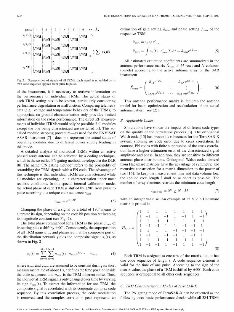
Fig. 2. Superposition of signals of all TRMs. Each signal is scrambled by itsown code sequence applied from pulse to pulse.
of the instrument, it is necessary to retrieve information onthe performance of individual TRMs. The actual status ofeach TRM setting has to be known, particularly consideringperformance degradation or malfunction. Comparing telemetrydata (e.g., voltage and temperature behaviors of the TRMs) toappropriate on-ground characterization only provides limitedinformation on the radar performance. The direct RF measure-ments of individual TRMs would only be possible if all modulesexcept the one being characterized are switched off. This so-called module stepping procedure—as used for the ENVISATASAR instrument [7]—does not represent the actual status ofoperating modules due to different power supply loading inthis mode.
A detailed analysis of individual TRMs within an activephased array antenna can be achieved by a coding technique,which is the so-called PN gating method, developed at the DLR[8]. The name “PN gating method” refers to the possibility ofscrambling the TRM signals with a PN code. The advantage ofthis technique is that individual TRMs are characterized whileall modules are operating, i.e., a characterization under mostrealistic conditions. In this special internal calibration mode,the actual phase of each TRM is shifted by ±90◦ from pulse topulse according to a unique code sequence cmn
cmn = e±j90◦. (3)
Changing the phase of a signal by a total of 180◦ means toalternate its sign, depending on the code bit position but keepingits magnitude constant (see Fig. 2).
The total phase commanded for a TRM is the phase ϕmn ofits setting plus a shift by ±90◦. Consequently, the superpositionof all TRM gains amn and phases ϕmn at the composite port ofthe distribution network yields the composite signal sc(t), asshown in Fig. 2
sc(t) =M−1∑m=0
N−1∑n=0
cmn(t) · amnejϕmn + nmn (4)
where amn and ϕmn are assumed to be constant during its shortmeasurement time of about 1 s, t defines the time position insidethe code sequence, and nmn is the TRM inherent noise. Thus,the individual TRM signal is only changed over time by varyingits sign cmn(t). To extract the information for one TRM, thecomposite signal is correlated with its conjugate complex codesequence. By this correlation process, the code modulationis removed, and the complex correlation peak represents an
estimation of gain setting amn and phase setting ϕmn of therespective TRM
xmn = sc ⊗ c∗mn
xmn =∫
sc(t) · c∗mn(t) dt = amnejϕmn . (5)
All estimated excitation coefficients are summarized in theantenna performance matrix Xmn of M rows and N columns(panels) according to the active antenna array of the SARinstrument
Xmn =
⎛⎝
a11ejϕ11 · · · a1Nejϕ1N
.... . .
...aM1ejϕM1 · · · aMNejϕMN
⎞⎠ . (6)
This antenna performance matrix is fed into the antennamodel for beam optimization and recalculation of the actualantenna pattern [see (2)].
B. Applicable Codes
Simulations have shown the impact of different code typeson the quality of the correlation process [3]. The orthogonalWalsh code [15] has proven its robustness for the TerraSAR-Xsystem, showing no code error due to cross correlation. Incontrast, PN codes with finite suppression of the cross correla-tion have a higher estimation error of the characterized signalamplitude and phase. In addition, they are sensitive to differentantenna phase distributions. Orthogonal Walsh codes derivedfrom Hadamard matrices have the advantage of symmetric andrecursive construction for a matrix dimension to the power oftwo [16]. To keep the measurement time and data volume low,the applied code length l shall be as short as possible. Thenumber of array elements restricts the minimum code length
lmodule = 2w ≥ N · M (7)
with an integer value w. An example of an 8 × 8 Hadamardmatrix is printed in
H8×8 =
⎛⎜⎜⎜⎜⎜⎜⎜⎜⎜⎝
1 1 1 1 1 1 1 11 −1 1 −1 1 −1 1 −11 1 −1 −1 1 1 −1 −11 −1 −1 1 1 −1 −1 11 1 1 1 −1 −1 −1 −11 −1 1 −1 −1 1 −1 11 1 −1 −1 −1 −1 1 11 −1 −1 1 −1 1 1 −1
⎞⎟⎟⎟⎟⎟⎟⎟⎟⎟⎠
.
(8)
Each TRM is assigned to one row of the matrix, i.e., it hasone code sequence of length l. A code sequence element isvalid for the time of one pulse. According to the sign of thematrix value, the phase of a TRM is shifted by ±90◦. Each codesequence is orthogonal to all other code sequences.
C. TRM Characterization Modes of TerraSAR-X
The PN gating mode of TerraSAR-X can be executed as thefollowing three basic performance checks while all 384 TRMs
Authorized licensed use limited to: Deutsches Zentrum fuer Luft- und Raumfahrt. Downloaded on March 24, 2009 at 03:27 from IEEE Xplore. Restrictions apply.

BRÄUTIGAM et al.: EFFICIENT METHOD FOR PERFORMANCE MONITORING OF ACTIVE PHASED ARRAY ANTENNAS 1239
are simultaneously operated:• module level with a minimum of 512 code bits for 384
TRMs;• panel level with a minimum of 16 code bits for 12 panels;• row level with a minimum of 32 code bits for 32 rows.As the antenna beams are realized by applying row-wise ex-
citation settings for elevation steering and panelwise excitationsettings for azimuth steering, row and panel level checks arewell suited for characterizing the beam excitations. For rowlevel check, all modules of one antenna row are assigned tothe same code sequence. Thus, the row level check provides anaveraged estimation of the excitation setting for each row and,consequently, the 32 antenna beam settings in elevation. Panellevel check means averaging over all subarray modules withinone panel. The final result of all panels describes the antennaazimuth settings.
Although the minimum number of bits for each PN gatingmeasurement is sufficient, a longer code length helps to im-prove correlation quality. Thus, for TerraSAR-X, row and panellevel measurements are executed with 64 code bits each. Thetotal measurement time is driven by the number of pulses perbit and the commanded pulse repetition frequency. It is on theorder of 1 s for each mode.
D. Advanced TRM Failure Check
For health check of the front end, it is necessary to get areliable feedback on failed TRMs, as this is a strong indicationfor instrument contingencies. During satellite operations, a fastbut reliable failure diagnosis is necessary. This can be realizedwith an advanced TRM failure check method, as failed TRMsare detected by lower power levels of the respective row andpanel at the affected array element position.
The total number of measured calibration pulses can besignificantly reduced by only measuring the antenna array onrow and panel levels consecutively. The total code length ofboth code sequences from panel and row level checks is
l′panel = 2u ≥ N l′row = 2v ≥ M (9)l′panel + l′row = 2u + 2v ≥ N + M (10)
with integer values u and v. For N and M greater than two, itcan be derived that the total number of code pulses is less thanfor the code length lmodule of a module level check
N + M < N · M (11)l′panel + l′row < lmodule. (12)
In the case of TRM failure, the total power level will de-crease. The defective TRM can be identified by a lower powerlevel at positions n and m in the respective panel and row.
Fig. 3 shows the code length required for an array of Mrows and N panels (with M = N ), comparing both methods.Increasing array size leads to a lower increase of required codelength for the advanced TRM failure check. For TerraSAR-X,the row and panel level checks need at least 48 different codedcalibration pulses in sum (l′panel = 16; l′row = 32). In contrastto module level check with 512 code bits, the advanced TRMfailure check is up to ten times faster than individual TRMcharacterization.
Fig. 3. Minimum code length for M rows and N panels with M = N .
Fig. 4. Sum of 384 signals with signed code sequences of 512 code bits.The composite signal of boresight beam has a higher dynamic range than thegeometric coding beam.
E. Dynamic Range of Composite Signal
For best signal-to-noise ratio in the internal calibration fa-cility, the instrument is operated in boresight condition, i.e.,all TRM gains and phases are set to equal and constant valuesduring measurement. However, for PN gating with orthogonalWalsh codes, each TRM signal is furthermore modulated witha unique code (see Fig. 2).
Assuming equal gains for all TRMs, the composite signalreduces to a noiselike signal when the TRM phase excitationsare scrambled. The only exception is for code bits where allsigns are equal; compare the first column of (8). Here, theindividual TRM signals coherently sum up to a high powerlevel. Fig. 4 shows the sum of 384 coded signals over time ina module level check. The dashed line shows the high dynamicrange for PN gating on boresight beam, which may lead to anonideal saturation degree of the receiver.
Although TerraSAR-X is fully qualified for this high dy-namic range of module level measurements, the drop of powerlevel can be eliminated by choosing another underlying beaminstead of boresight condition. While applying the PN gatingcode sequences to the TRMs over time, the underlying beamcan have an additional phase distributed over the array antennageometry. In an iterative process, the antenna phases are chosenby optimizing for the smallest dynamic range over time, whenthe overall sum signal is composed with the PN code sequence.
Authorized licensed use limited to: Deutsches Zentrum fuer Luft- und Raumfahrt. Downloaded on March 24, 2009 at 03:27 from IEEE Xplore. Restrictions apply.

1240 IEEE TRANSACTIONS ON GEOSCIENCE AND REMOTE SENSING, VOL. 47, NO. 4, APRIL 2009
Fig. 5. Antenna performance matrix of TerraSAR-X antenna. Normalized TXamplitude estimation derived from module level check with one TRM switchedoff at position 8/17 (light gray: Full performance; dark gray: Failure).
By this “geometric coding,” the underlying beam contributesan additional constant phase distribution during PN gatingmeasurement, avoiding the coherent superposition of equallyphased TRMs like in boresight condition. Thus, the powerlevel of the composite signal for the first code bit is reduced,while the remaining part of the code sequence has more signalvariation (see solid line in Fig. 4).
IV. ON-GROUND VERIFICATION OF ESTIMATION METHOD
The following several cases of performance degradation havebeen studied during on-ground verification activities:
1) single TRM failure;2) malfunction of half a panel (16 TRMs) in a tapered beam;3) gain and phase degradation of several TRMs.
The checks were executed as module, row, and panel levelson the TerraSAR-X antenna with 384 TRMs and compared toacquired reference sets without malfunction.
A. TRM Failure From Module Level Check
In the instrument configuration, one TRM was switchedoff. The results of a module level check are plotted into anantenna performance matrix representing the antenna TRMconfiguration of TerraSAR-X. Fig. 5 shows the estimated gainsin TX. High power levels are light gray, and low power levelsare dark gray. The evaluation shows a significant decrease ingain for the switched-off TRM. The position of the detectedfailed element is at the expected place that conforms to theassigned code at column 8 and row 17.
The degraded array element is written into the antennaperformance matrix Xmn, which is an important input for theantenna model (6). Although few affected modules do not in-fluence the total antenna performance, the antenna patterns canbe recalculated in the case of several failures or module drifts.
B. TRM Failure From Panel and Row Level Check
In further measurement, the advanced TRM failure checkfrom (12) is applied to the TerraSAR-X array with a switched-
Fig. 6. (Top) Row level check of antenna with switched-off TRM. Gaindegradation at row 17 is visible for TX and RX. (Bottom) Panel level checkof antenna with switched-off TRM. Gain degradation at panel 8 is visible forTX and RX. Plots show the difference to reference measurement.
off TRM. Fig. 6 shows the effectiveness of this diagnosismethod. It shows that the positions of failed modules aredetected by reducing the analysis to panel and row levelchecks. As for module level check, the switched-off TRM canbe identified by the lower gain in row 17 and panel 8. The PNgating technique is accurate enough to show small differenceson the order of few tenths of a decibel compared to nominalreference configuration.
Instead of applying a code of 512 bits length like for modulelevel check, an equivalent meaningful result could be foundmuch faster by combining two measurements of code lengthl′ = 64 each for panel and row level checks. These two checkswith shorter code lengths decrease the measurement time anddata volume by a factor of four.
C. Panel Malfunction in a Tapered Beam
Applying the PN gating technique on a nominal ta-pered beam (like for stripmap mode) yields the actual beamcoefficients set in the TRMs. The determined excitation can becompared to the commanded one and is fed into the antennamodel for calculating the real antenna pattern.
Half a panel (16 TRMs) was switched off, whereas theantenna was excited with a gain taper in elevation direction. Thecommanded taper in elevation applied to all panels is drawn as asolid line in Fig. 7. By module level check, individual subarrayelements are measured. Thus, the estimated gain over eleva-tion can be analyzed for each panel separately. The measuredelevation excitations are compared to the commanded ones.The estimated gain of panel 0 is plotted as a dashed line. Itmatches the commanded beam taper very well. Accordingly,the gain characteristics of (dotted line) panel 10 correspond tothe expected values, too. The first 16 TRMs of panel 10 yieldonly noise signal, as these TRMs were switched off.
D. Gain and Phase Estimation
Several TRMs were commanded with different excitationcoefficients in gain and phase compared to boresight operation.Panels 8 and 9 were commanded with a shift of +45◦ in TX
Authorized licensed use limited to: Deutsches Zentrum fuer Luft- und Raumfahrt. Downloaded on March 24, 2009 at 03:27 from IEEE Xplore. Restrictions apply.

BRÄUTIGAM et al.: EFFICIENT METHOD FOR PERFORMANCE MONITORING OF ACTIVE PHASED ARRAY ANTENNAS 1241
Fig. 7. Commanded and measured beam taper on panel 0 and panel 10 ofTerraSAR-X antenna. The first 16 TRMs in panel 10 were switched off.
Fig. 8. On-ground measurements of antenna in TX and RX. Each data setis referenced to its maximum value. (Above) Gain degradation of −2.4 dBin RX for TRMs 64 to 127 corresponding to panels 2 and 3. (Below) Phasedegradation of +45◦ at TRMs 256 to 319 corresponding to panels 8 and 9.
phase, while panels 2 and 3 were attenuated by 2.3 dB for RXgain. All other panels had nominal settings of 0 dB attenuationand 0◦ phase in TX and RX.
Fig. 8 shows all TRM characteristics for TX and RX behav-iors of the antenna. After averaging over all elements of onepanel, the estimated TX phase of panels 8 and 9 was +45◦, asconfigured. The estimated RX gain of panels 2 and 3 resultsin −2.4 dB, only deviating by 0.1 dB from the commandedvalue.
After achieving these excellent results of the on-ground ver-ification, PN gating is applied as an essential TRM character-ization method for in-orbit performance monitoring. The totalaccuracy of repeated spaceborne measurements is summarizedin the following sections.
Fig. 9. Comparison of first in-flight measurement to on-ground reference. TheRX gain of all TRMs is shown. On-ground and in-flight results are normalizedto each other. TRM at position 273 is switched off and has a gain of less than−20 dB. TRMs at positions 45, 260, and 282 show degradations of more than2 dB compared to their on-ground statuses.
Fig. 10. Measurement variation of three neighbored TRMs over mission time.TRM 282 is one of the three degraded TRMs for the RX case. It has the highestvariation of RX gain. Neighbored TRMs 281 and 283 show much more stablebehavior.
V. IN-ORBIT TRM PERFORMANCE MONITORING
One of the first test data takes after satellite launch, and in-strument switch-on was a PN gating TRM measurement. Asidefrom the functional verification of the mode, this gave a fasttelemetry-independent look on the performance of the TRMs.There are 384 excitations each for TX and RX gains, as well asfor TX and RX phases; thus, a total of 1536 estimations exist.The first in-flight results show very good accordance to the on-ground reference, as plotted for the RX amplitude in Fig. 9.
Comparing all 1536 measurements to their on-ground ref-erence, more than 99% of all excitations correspond to theexpected result. This proves the robustness of the PN gat-ing technique, confirming the on-ground verification of thismethod. It has to be mentioned that one TRM was intentionallyswitched off before launch as it showed anomalies. This con-dition will be kept during the whole satellite mission to avoidnegative influences (compare row 17 of panel 8 in Fig. 5). Threemodules at position 45, 260, and 282 work outside the expectedperformance range in RX operation. Their actual degradationbetween 2 and 6 dB is successfully determined with repeated
Authorized licensed use limited to: Deutsches Zentrum fuer Luft- und Raumfahrt. Downloaded on March 24, 2009 at 03:27 from IEEE Xplore. Restrictions apply.

1242 IEEE TRANSACTIONS ON GEOSCIENCE AND REMOTE SENSING, VOL. 47, NO. 4, APRIL 2009
Fig. 11. In-orbit variation of individual TRMs for 42 different measurements of TX behavior. Each asterisk represents one evaluated measurement point. Thesolid curve represents the mean value of all measurement results per TRM. (Left) TX amplitude. (Right) TX phase.
TRM measurements during the commissioning phase. TRMposition 282 has been identified with the highest variationover repeated measurements. In Fig. 10, the solid line showsits variation over time by plotting its derived excitation. Thedashed lines are the neighbored TRMs plotted for comparison.As the long-term variation is still small enough for all TRMs,no action is necessary. However, the plots emphasize the needfor long-term TRM performance monitoring and trend analysis.Considering the three degraded RX modules after launch, PNgating measurements become stringent in terms of efficient androbust individual TRM characterization.
VI. MEASUREMENT ACCURACY
During the five months of commissioning phase, numerousPN gating checks have been executed in order to monitor theTRM performance. In total, the in-flight monitoring comprisesthe evaluation of about 100 data sets including the following:
• 42 module level acquisitions;• 25 row level acquisitions;• 25 panel level acquisitions.The actual excitation of each module can be measured for
TX and RX gains, as well as for TX and RX phases. Thus, intotal, four times 384 measurements are available for each PNgating acquisition. For monitoring the stability, all evaluationsare normalized to the first in-flight measurement. The individualTRM stabilities during the mission time are then easily visible.
Fig. 11 shows the estimated TX excitation settings derivedfrom 42 module level measurements during the commissioningphase. The solid line through all points connects the meanvalues of these measurements to provide the average offsetcompared to the reference values. The evaluation of all settingsshows a very stable behavior of the TRMs. The results providethe following two points of information for each element.
1) The reference offset of one element specifies the actualexcitation coefficient (compared to boresight).
2) The standard deviation of each element comprises thesetting accuracy of the TRMs, their variation, and the PNgating estimation accuracy.
Table II summarizes the standard deviation for the module,row, and panel level measurements. The TRM at position 273,which is switched off, has been masked out for this analysis,as noise signals falsify the measurement accuracy with their
TABLE IISTANDARD DEVIATION OF REPEATED MEASUREMENTS
inherent gain and phase instabilities (see variations at position273 in Fig. 11). Looking at the amplitude accuracies in Table II,the TRMs are more stable in TX. This is due to better signal-to-noise ratio of the whole chain for TX than for RX. Asthe accuracy of the PN gating method itself is part of theoverall measurement accuracy of the TX case, this new TRMcharacterization method is hence better than the following:
• 0.09 dB for amplitude;• 1.9◦ for phase.
Finally, the presented PN gating method demonstrates thehigh stability of the TerraSAR-X TRMs over the completeduration of the commissioning phase. The TRMs perform betterthan 0.1 dB for TX gain and 0.2 dB for RX gain, and 2.0◦ forTX phase and 1.3◦ for RX phase.
VII. CONCLUSION
SARs with active phased array antennas depend on thereliable performance of its electronic instrument components.For the TerraSAR-X satellite, the stability of its 384 TRMsis of crucial importance for fast and flexible generation ofvarious antenna beams. The flexibility of TerraSAR-X can beunderlined with its ability to demonstrate new SAR modes andthe introduction of innovative calibration concepts [2], [3].
Implementing the novel PN gating method is an importantmilestone for the successful calibration and dynamic optimiza-tion of the whole system during mission lifetime. The PNgating method allows operating all TRMs under most realisticconditions with the advantage that all individual modules canbe characterized simultaneously. During on-ground characteri-zation of the TerraSAR-X radar instrument, this technique hasalready been established as an essential diagnostic tool forfunctional checks, as well as TRM drift and failure monitoring.
Authorized licensed use limited to: Deutsches Zentrum fuer Luft- und Raumfahrt. Downloaded on March 24, 2009 at 03:27 from IEEE Xplore. Restrictions apply.

BRÄUTIGAM et al.: EFFICIENT METHOD FOR PERFORMANCE MONITORING OF ACTIVE PHASED ARRAY ANTENNAS 1243
PN gating acquisitions are possible as different level checksbased on module, panel, and row-wise measurements. Modulelevel checks provide precise estimations of TRM characteristicsin amplitude and phase, detecting performance degradation ormodule failure of individual TRMs. Combined row and panellevel checks accelerate the process of TRM failure detection bylocalizing gain degradation inside the whole antenna.
For the first time ever, this innovative method is applied ina spaceborne environment on the TerraSAR-X mission. Theresults from repeated in-orbit measurements prove the highestimation accuracy of the PN gating technique of better than0.09 dB for amplitude and 1.9◦ for phase estimation of individ-ual TRMs.
The fast and accurate estimation of individual TRM settingsduring the lifetime of the SAR instrument is a valuable supportfor in-orbit characterization and performance stability monitor-ing. As proven for TerraSAR-X, the evaluation of all measure-ments shows that PN gating is an excellent method for detectingTRM failures and characterizing instrument degradation. Fur-thermore, the technique described in this paper is applicable forthe characterization and calibration of other advanced sensorsystems featuring active phased array antennas.
REFERENCES
[1] S. Buckreuss, W. Balzer, P. Mühlbauer, R. Werninghaus, and W. Pitz,“The TerraSAR-X satellite project,” in Proc. 25th IEEE Int. Geosci. Re-mote Sens. Symp., Toulouse, Frankreich, 2003, pp. 3096–3098.
[2] M. Schwerdt, B. Bräutigam, M. Bachmann, B. Döring, D. Schrank, andJ. Hueso, “Final results of the efficient TerraSAR-X calibration method,”in Proc. IEEE Radar Conf., Rome, Italy, 2008, pp. 1175–1180.
[3] M. Schwerdt, D. Hounam, B. Bräutigam, and J. L. Alvarez-Pérez,“TerraSAR-X: Calibration concept of a multiple mode high resolutionSAR,” in Proc. 25th IEEE Int. Geosci. Remote Sens. Symp., Seoul, Korea,2005, pp. 4874–4877.
[4] B. Bräutigam, M. Schwerdt, and M. Bachmann, “In-flight monitoring ofTerraSAR-X radar instrument stability,” in Proc. IRS, Cologne, Germany,2007.
[5] W. Pitz, “The TerraSAR-X satellite,” in Proc. 6th Eur. Conf. SyntheticAperture Radar, Dresden, Germany, 2006.
[6] M. Wahl, “High precision T/R module for SAR earth observation,” inProc. 6th Eur. Conf. Synthetic Aperture Radar, Dresden, Germany, 2006.
[7] C. Buck, “ASAR instrument gain monitoring,” ESTEC, European SpaceAgency (ESA), ENVISAT ASAR Calibration Review (ECR), 2002.
[8] D. Hounam, M. Schwerdt, and M. Zink, “Active antenna module charac-terisation by pseudo-noise gating,” in Proc. 25th ESA Antenna WorkshopSatellite Antenna Technol., Noordwijk, The Netherlands, 2002.
[9] B. Bräutigam, M. Schwerdt, M. Bachmann, and M. Stangl, “Individ-ual T/R module characterisation of the TerraSAR-X active phased arrayantenna by calibration pulse sequences with orthogonal codes,” in Proc.27th IEEE Int. Geosci. Remote Sens. Symp., Barcelona, Spain, 2007,pp. 5202–5205.
[10] B. Bräutigam, M. Schwerdt, and M. Bachmann, “The external calibrationof TerraSAR-X, a multiple mode SAR-system,” in Proc. 6th Eur. Conf.Synthetic Aperture Radar, Dresden, Germany, 2006.
[11] B. Döring, M. Schwerdt, and R. Bauer, “TerraSAR-X calibration groundequipment,” in Proc. WFMN, Chemnitz, Germany, 2007, pp. 86–90.
[12] M. Bachmann, M. Schwerdt, B. Bräutigam, B. Grafmüller, A. Herschlein,and J. L. Alvarez-Pérez, “The TerraSAR-X antenna model approach,” inProc. ITG Conf. Antennas, Munich, Germany, 2007, pp. 139–142.
[13] M. Bachmann, M. Schwerdt, and B. Bräutigam, “TerraSAR-X in-orbitantenna model verification results,” in Proc. EuRAD, Munich, Germany,2007, pp. 9–12.
[14] in Antenna Theory: Analysis and Design. Hoboken, NJ: Wiley, 1997.[15] S. D. Silverstein, “Application of orthogonal codes to the calibration of
active phased array antennas for communication satellites,” IEEE Trans.Signal Process., vol. 45, no. 1, pp. 206–218, Jan. 1997.
[16] J. H. Dinitz, Contemporary Design Theory: A Collection of Surveys.Hoboken, NJ: Wiley, 1992.
Benjamin Bräutigam received the Dipl.Ing. degreein electrical engineering from the Technical Univer-sity Karlsruhe, Karlsruhe, Germany, in 2003.
In 2003, he was a Visiting Scientist at the En-vironmental Technology Laboratory of the NationalOceanic and Atmospheric Administration, Boulder,CO. Since 2004, he has been with the Microwavesand Radar Institute, German Aerospace Center,Wessling, Germany. Since then, he has been in theradar calibration group responsible for internal in-strument calibration in spaceborne SAR projects like
TerraSAR-X, TerraSAR-L, TanDEM-X, and Global Monitoring Environmentand Security Program Sentinel-1. His major research interests include thedevelopment and analysis of innovative methods for instrument calibration andperformance monitoring.
Marco Schwerdt received the Dipl.Ing degree inelectrical engineering and the Doctorate (Dr. Ing.)degree, with a thesis on electrooptical E-field sen-sors, from the Technical University of Berlin, Berlin,Germany.
Since 1998, he has been with the Microwaves andRadar Institute, German Aerospace Center (DLR),Wessling, Germany, working on SAR calibrationmethods and performance analysis tools. Since 2000,he has been the head of the Radar CalibrationGroup, performing various radar calibration activ-
ities for different SAR missions like XSAR/SRTM or the ScanSAR modeof ASAR/ENVISAT. He is responsible for the successful calibration of thewhole SAR system of the German TerraSAR-X satellite mission, launched in2007. Currently, all preparations are made to calibrate the TanDEM-X system.Furthermore, as part of the Global Monitoring Environment and SecurityProgram, he is responsible for developing the overall SAR system calibrationand validation plan for the Sentinel-1 mission of the European Space Agency.Under his leadership, the DLR’s comprehensive radar calibration facilities,including novel tools for product quality control and performance analysis,have been maintained and extended. His major research interest includes thedevelopment of innovative and efficient calibration methods.
Dr. Schwerdt received the Award “Der Deutsche Gründerfonds” in 1997 forestablishing an enterprise of manufacturing electrooptical field sensors underthe patronage of the German Federal Minister for Science and Research.
Markus Bachmann received the Dipl.Ing. degree inelectrical engineering from the Technical Universityof Karlsruhe, Karlsruhe, Germany, in 2005.
Since 2005, he has been with the Microwavesand Radar Institute, German Aerospace Center,Wessling, Germany, where he is working as aCalibration Engineer in SAR calibration. In theTerraSAR-X project, he is responsible for theantenna model calibration, and in TanDEM-X forthe digital elevation model calibration concept.
Authorized licensed use limited to: Deutsches Zentrum fuer Luft- und Raumfahrt. Downloaded on March 24, 2009 at 03:27 from IEEE Xplore. Restrictions apply.