an analytical approach for dynamic response of timber ... · an analytical approach for dynamic...
TRANSCRIPT

952
An analytical approach for dynamic response of timber railroad bridges
A. S. UPPAL
Bridges and Structures, Canadian National Railways, 10004 - 104 Avenue, Edmonton, Alta., Canada T5J 0K2
AND
R. B. PINKNEY AND S. H. RIZKALLA
Department of Civil Engineering, University of Manitoba, Winnipeg, Man., Canada R3T 2N2
Received August 12, 1988
Revised manuscript accepted May 23, 1990
In the 1970s, it was reported that there were approximately 3700 track kilometers of timber railroad bridges in the United States and Canada. For short spans, they offer an attractive alternative to other types of bridges, as they are economical, faster to construct, and easy to maintain. Current design practices do not allow an independent consideration of the effects of the dynamic loads in sizing the bridge components, because very little information is available on the subject. Dynamic tests were carried out in 1986 on timber bridge spans at two test sites using test trains consisting of a locomotive unit, two loaded hopper cars, and a caboose. This paper gives a brief description of the analytical approach employed for determining the dynamic response of timber bridge spans under railway vehicles travelling at a constant speed. The model comprises a multi-degree-of-freedom system with each vehicle having bounce, pitch. and roll movements. Two parallel chords. each having its distributed mass lumped at discrete points, were used to idealize the bridge spans. A computer program developed on this basis was used to predict the loads at the wheel - rail interfaces and the vertical displacements at the discrete points on the spans. The predicted loads at wheel-rail interfaces and the maximum vertical displacements were found to be in agreement within about 20% and 16% respectively of the measured values. The program was utilized to study the effect of speed and other factors on the dynamic response of open-deck and ballast-deck bridges.
Key words: analytical approach, timber railway bridge. railway locomotive and cars. constant speed, wheel-rail interface, loads, displacements. accelerations, dynamic response.
Dans les annees 1970, des rapports faisaient etat de l'existence d'environ 3700 km de voie ferree sur des ponts de bois au Canada et aux Etats-Unis. Lorsque les travees sont COUrtes, ils constituent une solution interessante, car ils sont economiques, de construction rapide et faciles d'entretien. Les methodes de conception actuelles ne tiennent pas compte de fa~on independante des effets des charges dynamiques au moment du choix des composantes du pont parce qu'il existe tres peu d'information 11 cet effet. Des essais dynamiques ont ete effectues sur deux ponts de chemin de fer de bois, 11 l'aide de trains d'essai comportant une locomotive, deux wagons 11 tremie charges et un fourgon de queue. Cet article decrit brievement la methode analytique utilisee afin de determiner la reponse dynamique des travees de pont de bois sous des wagons circulant 11 une vitesse constante. Le modele comporte un systeme a plusieurs degres de liberte, chaque vehicule ayant des mouvements de rebondissement, de tangage et de roulement. Deux membrures paralleles ayant chacune leur masse repartie concentree en des points discrets ont ete utilisees pour predire les charges aux interfaces roues-rails et les deplacements verticaux aux points discrets des travees. Les differences entre les previsions des charges aux interfaces roues-rails et des deplacements verticaux maximums et les valeurs mesurees variaient respectivement de 20 et 16%. Le programme a servi a etudier l'effet de la vitesse et autres facteurs sur la reponse dynamique de ponts a tablier superieur ouvert et de ponts a tablier superieur avec empierrement.
Mots cies : methode analytique, pont de chemin de fer de bois, locomotive et wagos de chemin de fer, vitesse constante, interface roues-rails, charges, deplacements, accelerations, reponse dynamique.
[Traduit par la Redaction]
Can. J. Civ. Eng. 17, 952-964 (1990)
Introduction
The problem of the dynamic response of bridges has interested researchers since the middle of the nineteenth century. Willis (1849) gave an approximate solution for the case of a single constant load over a beam of a negligible mass. An exact solution of the equation he formulated was obtained by Stokes (1934). Later, Timoshenko (1922) pointed out three major causes of vibrations in railroad bridges: the live load effect of a smoothly rolling load, the impact effect of the balance weights of the locomotive driving wheels, and the impact effect due to irregularities of the track and flat spots in the wheels. He examined two possible extreme cases of the live
load effect: that the mass of the~oving load is either large or small in comparison with the mass of the beam, for a simply supported beam using the method of expansion of the eigenfunctions. Lowan (1935) solved the latter case with the aid of Green's function. Timoshenko also solved the problem of the effect of the balance weights by using a harmonic force moving over a beam at a constant speed.
The problem involving both the load mass and the beam mass, being more complicated, was examined much later by leffcott (1929), whose iterative method became divergent in some cases. Different approaches were attempted by Fryba (1972), Wen (1960), and Bolotin (1952).
NOTE: Written discussion of this paper is welcomed and will be received by the Editor until April 30, 1991 (address inside front cover). PriDIod in Canada I Imprime au Canada
Inglis (1934) used harmonic analysis to solve several practically important cases of dynamics of railway bridges traversed by steam locomotives, i.e., motion of a concentrated force. sprung and unsprung masses and harmonic forces acting on a beam, etc. His results were in excellent agreement with the
> UPPAL ET AL.: 2 953
Secondary
CAR BODY
+ Su spens ion,k sy _~iiIiii!"=----==;ii=,J
Primary ~ Suspension, ksp
(a)
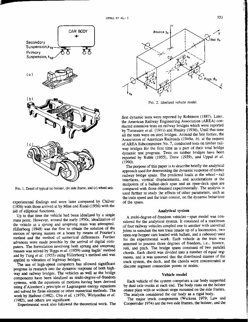
FIG. 1. Detail of typical (a) bolster. (b) side frame, and (c) wheel sets.
experimental findings and were later compared by Chilver (1956) with those arrived at by Mise and Kunii (1956) with the aid of elliptical functions.
Up to that time the vehicle had been idealized by a single mass point. However, around the early 1950s, idealization of the vehicle as a sprung and unsprung mass was attempted. Hillerborg (1948) was the first to obtain the solution of the motion of sprung masses on a beam by means of Fourier's methlXl and the methlXl of numerical differences. Further advances were made possible by the arrival of digital computers. The formulation involving both sprung and unsprung masses was solved by Biggs et al. (1959) using Inglis' methlXl and by Tung et al. (1955) using Hillerborg's method and was applied to vibration of highway bridges.
The use of high-speed computers has allowed significant progress in research into the dynamic response of both highway and railway bridges. The vehicles as well as the bridge components have been idealized as multi-degree-of-freedom systems, with the equations of motions having been derived using d' Alembert's principle or Lagrangean energy equations and solved by finite element or other numerical methlXls. The work by Hathout (1982), Chu et al. (1979), Wiriyachai et al. (1982), and others are significant.
Experimental work also followed the theoretical work. The
y
FIG. 2. Idealized vehicle model.
first dynamic tests were reported by Robinson (1887). Later, the American Railway Engineering Association (AREA) conducted extensive tests on railway bridges which were reported by Turneaure et al. (1911) and Hunley (1936). Until that time all the tests were on steel bridges. Around the late forties, the Association of American Railroads (1949a , b), at the request of AREA Subcommittee No.7, conducted tests on timber railway bridges for the first time as a part of their total bridge dynamic test program. Tests on timber bridges have been reported by Ruble (1955), Drew (1959), and Uppal et al. (1990).
The purpose of this paper is to describe briefly the analytical approach used for determining the dynamic response of timber railway bridge spans. The predicted loads at the wheel-rail interfaces, vertical displacements, and accelerations at the midpoints of a ballast-deck span and an open-deck span are compared with those obtained experimentally. The analysis is used further to studyj}e effects of other parameters, such as the train speed and the train consist, on the dynamic behaviour of the spans.
Analytical system
A multi-degree-of-freedom vehicles-span model was considered for the analytical system. It consisted of a maximum of four railway vehicles coupled one to another with universal joints to simulate the test train (made up of a locomotive, two open-top hopper cars loaded with ballast, and a caboose) used for the experimental work. Each vehicle in the train was assumed to possess three degrees of freedom, i.e., bounce, roll, and pitch. The bridge spans consisted of two parallel chords. Each chord was divided into a number of equal segments, and it was assumed that the distributed masses of the track system, the deck, and the chords were concentrated at discrete segment connection points or nodes.
Vehicle model
Each vehicle of the system comprises a car body supported by dual axle trucks at each end. The body rests on the bolster centre plate with or without stops mounted on the side frames. The analysis considered the car body as a rigid body.
The major truck components (Wickens 1979; Law and Cooperrider 1974) are the two side frames, the bolster, and the
,-.1
,
Ii
954 CAN. J. CIV. ENG. VOL 17, 1990
Open Deck Bridge Spon NO.52
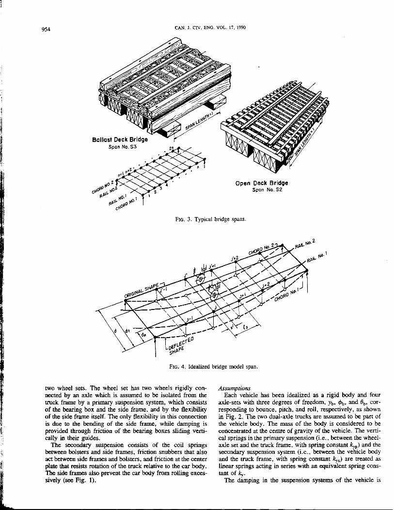
FIG. 3. Typical bridge spans.
FIG. 4. Idealized bridge model span.
two wheel sets. The wheel set has two wheels rigidly connected by an axle which is assumed to be isolated from the truck frame by a primary suspension system, which consists of the bearing box and the side frame, and by the flexibility of the side frame itself. The only flexibility in this connection is due to the bending of the side frame, while damping is provided through friction of the bearing boxes sliding vertically in their guides.
The secondary suspension consists of the coil springs between bolsters and side frames, friction snubbers that also act between side frames and bolsters, and friction at the center plate that resists rotation of the truck relative to the car body. The side frames also prevent the car lx>dy from rolling excessively (see Fig. 1).
Assumptions Each vehicle has been idealized as a rigid body and four
axle-sets with three degrees of freedom. YJ" <I>t" and Ob, corresponding to bounce, pitch. and roll. respectively, as shown in Fig. 2. The two dual-axle trucks are assumed to be part of the vehicle body. The mass of the body is considered to be concentrated at the centre of gravity of the vehicle. The vertical springs in the primary suspension (i.e .• between the wheelaxle set and the truck frame, with spring constant kyp) and the secondary suspension system (i.e., between the vehicle body and the truck frame, with spring constant kvs) are treated as linear springs acting in series with an equivaJent spring constant of k".
The ctamping in the suspension systems of the vehicle is

I I I
I UPPAL ET AL.: 2 955
small and assumed not to change while the vehicle traverses a short bridge span and is therefore neglected. The effects of lateral or longitudinal movements in the vehicle components caused by hunting, sway, or braking action are neglected. The couplings between the vehicles are provided by universal joints and so no motion is transferred from one vehicle to another. All vehicles in a train cross the bridge span at a constant speed.
Equations of motion Assuming no damping in the suspension systems and using
Newton's second law of motion, the equations of motion for a vehicle with three degrees of freedom can be expressed as follows:
8 M jJ, + E It- )Ii = 0
b , i=! "'Y r (vertical displacement)
(pitch displacement)
8
lb Ob + E ky y~(±de) = 0 (roll displacement) r r ;=1 r r
where y~ = (Yb ± licpb ± de8b - u~ ); u~ is the vertical displacement of the wheel- rail contact' point for the ith wheel at any time t; I! is the distance from the centre of gravity of vehicle to the ith wheel; de equals one-half of the distance between the wheel- rail contact points of a wheel-axle set: and r is the vehicle number.
By substituting the value of y~ and rearranging the tenus, [1] can be represented in the following matrix form:
[:b' I:, : 1 ~: + ky, [: 8(l?, : I~) : 1 ~ o 0 lb, Ob, 0 0 84, 8b,
8
E k" ui ±/~ i=! .' b
or simply
[2] [MyJ br} + [k"J {Yr} = {FyJ
where. as before. r refers to vehicle number. Similar expressions can be derived for other vehicles in the train and the entire train can be represented in matrix form.
Bridge span model A timber railroad bridge (American Railway Engineering
Association 1988) consists of relatively short spans supported by bents. The spans are made up of structural members called stringers, which run parallel to the track. The stringers may be simply supported or, alternatively, may be continuous over the bents and may be spaced apart or closely packed together in a chord under each rail. The spans are often classified according to the type of deck they carry, i.e., a ballast deck or an open deck as shown in Fig. 3. In a ballast deck, the track ties are partially embedded in ballast which is laid between the rails and wooden flooring planks secured to the stringers, whereas in an open deck the ties are laid transversely between the rails and the stringers.
M~'~TV
J i l' . ,
M~
J+I ' J+2 LSTRAIGHT LINES J
~
FIG. 5. Interaction between wheel and rail.
Assumptions A bridge span comprises two parallel chords (Le., beams)
which are simply supported over bents as shown in Fig. 4. Each chord was divided into a number of equal segments approximating the tie spacing in the case of an open deck. The distributed mass of track, deck, and chords was considered to be concentrated (or lumped) at the segment connections or nodes. Only a vertical degree of freedom was assigned to each node and only the fundamental mode of vibration was considered. All displacements were assumed to be small. The effect of rotary inertia was neglected. The span material was assumed to possess linear behaviour. The experimental work confirmed this to be valid within the limits of the operating loads. The span was considered to have viscous damping, which is proportional to the velocity of vibration. The bridge span was assumed to be at rest before the train of vehicles entered the span.
Equations of motion For a dynamic system possessing stiffness and damping,
such as a stringer chord with lumped masses, the following equations of motion were obtained by means of d' Alembert' s principle:
[3] [Me]{a(t)} + [Del {u(t)} + [Ke]{u(t)} = {Fe(x, t)}
in which [Me] is the mass matrix of a chord with m masses lumped at the nodal points. This is a diagonal matrix with m = (wig + AgP)/s, where w = dead weight of track and bed material, A~ = gross cross-sectional area of chord, p = mass density of the material of chord, and Is = length of chord segment. [Kc] is the stiffness matrix of a chord, which was obtained by inversion of the flexibility matrix, the elements of which were obtained by summing the flexibility influence coefficients (Thompson 1965). This is a symmetric matrix. [Dc] is the damping matrix of a chord. The viscous damping was taken as a linear combination of [Me] and [Ke], i.e.,
[Dc] = a[Me] + .8[Ke]
which for normal modes can be expressed in the following form:
[4] [Dc] = 2~wn[Mc]
where ~ is the damping coefficient of a chord as a fraction of

956
t .:>< o o .=
CAN. J. ClY. ENG. VOL. 17. 1990
VEHICLE 4 VEHICLE 3 VEHICLE 2
FIG. 6. Train model.
VEHICLE I
(a)
North
t "., o c .=
-
(b)
~
Slough Crossing at km 26.55 Oak Point Subdivision
Sase of, Roll Ballast Deck
3.44m 3.66m 3.02m
I4.1Sm
Slough Crossing at km 31.38 Oak Point Subdivision
Base of Roll
3.S4m 3.S8m 3.S1m
I !.13m
FIG. 7. (a) Ballast-deck bridge; (b) open-deck bridge.
Locomotive Hopper Car No. I Hopper Car No.2 Caboose
I I 3 4
I I 5 6
I I I I II 12 13 14
I Track
,.. Track
AXIS NO.
AXIS ~~~~ ______ +-~ __ ~r-~ ___ ~_·-_O_~_·~~+-~~ __ H __ ~_O~ __ • __ ~~~~~ ________ +-~~SPACING
796 796 em
FIG. 8. Test train.
critical damping; Wn is the circular frequency for the nth mode (for n = 1. it is the fundamental circular frequency); and u(t) , u(t). and il(t) are the vertical displacements, velocities. and accelerations, respectively, with respect to time t at nodal points.
Vebicle- bridge interaction
The vehicle - bridge interaction takes place at the wheelrail contact surfaces. The load that a wheel exerts on a rail is a function of the masses and the suspension systems of the vehicle and the characteristics of the span. These loads at the wheel- rail interfaces fluctuate continuously as the vehicles move over the bridge spans.
Similarly, the equations of motion for the second chord were derived and the two sets were combined to form the equations of motion for the bridge span.

UPPAL ET AL.: 2
TABLE 1. Bridge spans data
Particulars
1. Span length, 1 cm (in.) 2. No. of stringers per chord 3. Effective no. of stringers per chord 4. Nominal size of stringers, cm x cm (in. x in.) 5. Density of Douglas fir, p N/cm3 (lb/in.3)
6. Weight of track and deck per chord, N/cm (lb/in.)
7. Damping coefficient as percentage of critical damping, ~
8. No. of segments per chord, ns 9. Center-to-center spacing of chords, d cm (in.)
10. Distance of 1st rail to near side chord, dn cm (in.) 11. Distance of 2nd rail to near side chord, df cm (in.) 12. Modulus of elasticity of Douglas fir, E MPa (lb/in.2
)
Ballast-deck bridge, span 3
365.8 (144.00) 5 4
20.3 x 40.6 (8 x 16) 0.94252 x 10⁻² (0.34722 x 10⁻¹)
168.12 (96.00)
9.8 10
153.1 (60.28) 2.5 (0.97)
152.3 (59.97) 11376 (1.65 x 10⁶ )
NOTE: acceleration due to gravity. g = 9.815 rnls2 (386.4 in.ls2).
TABLE 2. Vehicle train data
Locomotive OTH Car Particulars CN #5608 CN #090159
1. Body mass, Mb kg 296.71 219.73 (lb·s2/in.) (654.14) (484.42)
2. Sprung mass associated with each wheel, Ms kg 32.08 25.41 (lb . s2/in.) (70.72) (56.02)
3. Unsprung mass associated with each wheel, Mu kg 5.01 2.05 (lb·s2/in.) (11.05) (4.53)
4. Body pitch moment of inertia, Ib kg . cm2 2.24 x 10¹⁰ 1.88 X 10¹⁰ (lb . in .. S2) (1.98 X 10⁷) (1.66 x 1Q1)
5. Body roll moment of inertia, lb kg' cm2 1.33 x 10¹⁰ 1.45 X 10¹⁰ (lb . in .. S2) (1.17 x 10⁶) (1.28 x 10⁶ )
6. Vertical spring stiffnesslwheel, Kv N/cm 5820 19 300 (lb/in.) (3324) (11 020)
7. Half distance between truck centers, ~ cm 518.2 483.2 (in.) (204.00) (190.25)
8. Half distance between two wheel-axle sets of a truck, lw cm 137.2 86..+ (in.) (54.00) (34.00)
9. Half distance between two wheel- rail points of a wheel- axle set, de cm 74.9 74.9 (in.) (29.50) (29.50)
10. Distance between last axle of one vehicle and first axle of following vehicle, Lv cm 0.00 351.2 (in.) (0.00) (138.25)
957
Open-deck bridge, span 2
350.5 (138.00) 4 3
20.3 x 40.6 (8 x 16) 0.94252 x 10⁻² (0.34722 x 10- 1)
OTH Car CN #090151
240.18 (529.50)
27.97 (61.66)
2.05 (4.53)
1.88 X 10¹⁰ (1.66 X 10⁷)
1.45 X 10¹⁰
(1.28 x 10⁶) 19300
(11 020) 483.2
(109.25)
86..+ (34.00)
74.9 (29.50)
210.0 (82.50)
40.28 (23.00)
6.2 10
154.9 (60.97) 2.6 (1.03)
152.5 (60.03) 11376 (1.65 x 10⁶)
Caboose CN #79715
71.39 (157.40)
6.85 (15.10)
2.05 (4.53)
0.31 X 10¹⁰ (0.27 x 1Q1) 0.27 X 10¹⁰
(0.24 x 10⁶)
2800 (1600) 418.8
(164.88)
86.4 (34.00)
74.9 (29.50)
301.0 (118.50)
NOTES: (i) The vertical damping constant of vehicle(s), C,. taken as 0 N . stcm (lb' stin.). (ii) Time step = 0.005 s or more for speeds less than 48.3 kmlh (30 mph); for speeds 48.3 kmIh and over, time step = 0.001 s.
Assumptions The wheels of the vehicle were assumed to remain in contact
with the rails at all times. The surfaces of the wheel treads were assumed smooth and round. The track surface irregularities were assumed to be small and negligible. The rails and bridge ties for the open deck and the flooring planks for the ballast deck were assumed to be pin-connected at the nodal points to the stringers.
Let us consider the ith wheel of the rth vehicle, as shown in Fig. 5. There are two masses, a sprung mass (i.e., part of the vehicle body), M. ' supported by a spring system of stiffness ky, (damping in'vehicle assumed to be zero) and the unsprung mass, Mu (i.e., the wheel and half of the axle), which is always in contact with the rail.
The load at the wheel- rail interface, Fi, for the ith wheel is given by the following expression (Biggs 1964):
[5] F, = (M~, + MUg + ky,y~ - M~,a~,
or, by rearranging the terms,
F: = M~,(g - af,) + ky,y~ - Mtg
where
y~ = (Yb, ± li~, ± dc8.a, - u~)
and r refers to the vehicle number. The displacement, ~ , can
also be expressed in terms of nodal displacements, uj and uj+ 1 I ! ~

-
~I
~l' 4.
!"
.'
~
,
958 CAN. J. CIV. ENG. VOL. 17. 1990
E E
I-
4
3
Z 2 w ~ w u <[
~ M
~
~ ~ --1 a.. I (j)
Ci r-
II Ii Ii ~f\ o
-0.5 o
II I" I
2
TIME (5)
I'
I
3 4
FIG. 9. Computed displacement versus time. Ballast-deck bridge. span S3; train at 48.3 kmIh (30 mph).
5
4 ~ ~ A
E E 3
I-Z w 2 ~
~ ~ w u <[ --1 a.. (j)
Ci
0
If\f\ -I I
0 2 TIME (5)
3 4
FIG. 10. Computed displacement versus time. Open-deck bridge. span S2; train at 48.3 kmIh (30 mph).
for chord 1 and U) and uj'+1 for chord 2, using linear interpolation by the following relationship:
u{" = 'Y(aiu)+l + (3iuj) + 'Y(aiUj'+l + (3iuj.)
Differentiating the above equation twice,
[6] at = 'Y(aiUj+l + (3iuj) + 'Y(aiUj'+l + (3IUj-)
The contributions of the effect of the ith and (i + l)th wheels on the chord segments j, j + 1 and j', j' + 1 were obtained assuming linear interpolation function and generalized coordinates (Clough and Penzien 1975) for rigid-body masses, stiffness, damping, and interaction forces.
Overall dynamic system
Each chord was divided into lis = n + 1 equal segments or n effective nodal points. Every node was assigned one degree of freedom, namely, the vertical displacement. Therefore, a
0.8
0.6
0.4
Z 0.2 o ti 0 cr w d - 0.2 U U <[ - 0.4
-0.6
- 0.8
o 3
TIME (5)
FIG. 11. Computed acceleration versus time. Ballast-deck bridge. span S3: train at '+8.3 km/h (30 mph).
z o ti cr W --1 W U U <[
1.6
1.2
2
TIME (5)
3 4
FIG. 12. Computed acceleration versus time. Open-deck bridge, span S2; train at 48.3 km/h (30 mph).
bridge span possessed 2n degrees of freedom. Further, there were three degrees of freedom assigned to each vehicle, so a train consisting of lear number of cars had 3lcar degrees of freedom. The overall dynamic system. therefore, comprised 2n + 3/= degrees of freedom.
From [1] -[6], the equations of motion for the overall trainbridge span system may be expressed as follows:
[7] [Mo]{D} + [co]{b} + [Ko]{D} = {Fo}
in which [Mo].' [Co], and [Kol are. respectively, the overall matrices of mass, damping, and stiffness and {Fo} is the vector of force including the effect of vehicle - bridge span interaction. {b}, {D}. and {D} are the vectors of accelerations. velocities. and displacements. respectively, at the nodal points of the span and other locations on the vehicles. The sizes of the matrices and the vectors for the overall system depend on the number of segments a bridge span is divided into and on the number of vehicles considered in a train.

r UPPAL ET AL.: 2 959
TABLE 3. Computed vertical displacements and accelerations at midpoint of open-deck bridge, span S2
Acceleration (x g)
Vertical displacement, mm (in.) Left rail Right rail
Train consist
Locomotive Locomotive and one car Locomotive and two cars Locomotive, two cars, and caboose
4
E 3 E
fZ
~ 2 w U <t ....J a.. Ul I Ci
Left rail Right rail
4.04 (0.159) 4.05 (0.159) 4.94 (0.194) 4.91 (0.193) 5.23 (0.206) 5.21 (0:205) 5.20 (0.205) 5.22 (0.206)
0.8 -0.5 oL---L.----:0:'-.2--.J......--:0,....4--..1---0...J..6--....J....-~
TIME (5)
FIG. 13. Computed displacement versus time. Open-deck bridge, span S2; locomotive at SO.5 kmih (50 mph).
5r---------~-----------~
fZ
4
~ 2 w ~ -l a.. I Ul o
_I L-....J...._...J._~....J...._...J._.J......~__l~..1__L.__l~....J....-:'-_~_l
o 0.2 0.4 0.6 0.8 1.0 1.2 1.4
TIME (5)
FIG. 14. Computed displacement versus time. Open-deck bridge, span S2; locomotive and one car at 80.5 krruh (50 mph).
Computer program
A computer program was developed to solve the equations of motion for the overall dynamic system using different methods of numerical integration. The outline of the proce-
Average
4.05 (0.159) 4.93 (0.194) 5.22 (0.206) 5.21 (0.205)
6
5
E 4
E
f- 3 Z w ~ w
2 U <t ....J a.. Ul 0
0
-10 0.2
Maximum
+5.22 +6.34 +7.43 +3.70
0.4 0.6
Minimum
-4.S9 -5.54 -7.S0 -3.03
Maximum
+6.76 +S.04 +7.32 +3.69
Minimum
-6.57 -10.14 -7.39 -2.S9
FIG. 15. Computed displacement versus time. Open-deck bridge, span S2; locomotive and two cars at SO.5 kmlh (50 mph).
6r-------------------------------~
5
E 4 E
f- 3 Z w ~
~ 2 <t ....J a.. ~ I
0.4 0.8 1.2 1.6 2.0 2.4
TIME (5)
FIG. 16. Computed displacement versus time. Open-deck bri<,lge. span S2; full train at 80.5 kmlh (50 mph).
dure of analysis employed in the program is given in the following steps: (i) Compute the constant parameters of the system and construct the mass and stiffness matrices for each vehicle and each chord individually from [2] and [3], respectively.

960
S ::l S '2 '5
"'0000"'1.0 00 r--- --t"""'i NMlf'ir-:o\ I I I I I
$;;;~~~ MM..r-ooci +++++
8~~~&l M..rlf'ir-:oci I I I I I
O~oor-~ r-C'"lIrl~1rl
MM..r-ooci +++++
V1~N~N ~ ~N~RlRl ~ SSeSe, < N ~ ~ ~~
If'ilf'i-or-:r-:
.-....-...-. .-...-. "'IrlNIrlOO O-Irl"' .... NNNNC'"l 00000 -- -- ------
V-;:;'=N"G' C-Irl"'~ NNNNC'l
Se8Se CC'"l"'-1rl N~C'"l~C'l
If'ilf'i-or-:-o
C'"lONON MN("f")-1.I"\ o\NoOr-:M r- 00 00 '" -----N .-..-...-. -...-.. C""'")\Or---O\C'"lr-O\-~
O""':N..r1f'i ~~~~~ o"'~r-O\ ~r--1rl0\
o\"';"':\Ci-= r-oo",,,,o ----N 8$8~0\ C'"l-r-~.,.,
oo"",:..ro ~~~~~
CAN. J. CIV. ENG. VOL. 17, 1990
(ii) Obtain the fundamental circular frequency of the chords by eigenvalue analysis, assuming undamped harmonic motion. Choose the damping coefficient for the chord and construct the damping matrix for the span using [4]. (iii) Establish the distance vectors from the configuration of wheels in each vehicle and distances between the vehicles as shown in Fig. 6. (iv) Choose a time step and calculate the position of the wheels by algebraically adding y' 1 = vt to all the terms of the distance vector and determine the number of wheels on a chord segment. (v) For every wheel, determine its position with respect to the chord segment it occupies. i.e., the distance ~ from nodes j and j + 1 (or j' and j' + 1 for the other chord) as shown in Fig. 5 and, using the general coordinates for mass, stiffness, and interacting force, determine the contributions of the wheel positions to be added to the overall mass. damping and stiffness matrices, and force vectors. (vi) Formulate the equations of motion of the overall dynamic system by constructing the overall mass, damping and stiffness matrices, and force vectors. (vii) Solve the equations of motion for the overall system by numerical integration using Newmark's ,a-method to find the dynamic displacements, velocities, accelerations, etc. (viii) Choose the next time step, t + ~t. and repeat the above procedure until the last axle of the train has gone past the span.
The computer program. written in FORTRAN VI, is quite flexible in that it can be used for any length of span having different material properties. Though at present no provision exists for track irregularities, the program could be adapted to incorporate the track line and surface irregularities. Up to four vehicles are currently included in a train. but the program can be expanded to include more than four vehicles. Initial values of displacements for different degrees of freedom can be specified for both vehicles and span for predicting their influences on the dynamic response of the system.
Numerical example
The numerical example is based on span ~o. 3 of the ballastdeck and span No.2 of the open-deck test bridges, respectively, as shown in Fig. 7. for which the measured data (Uppal et al. 1990) are available under the test train No.2 shown in Fig. 8 .
The data on the spans and the test train used as input for the program are given in Tables 1 and 2. The calculated fundamental frequency of the ballast-deck and open-deck spans were 22.4 and 34.2 Hertz per chord respectively.
Computer output
Figures 9 and 10 show typical computed displacement versus time plots for the midpoint of spans 3 and 2, respectively, for a train speed of 48.3 kmlh l30 mph). The maximum values of displacement occur at axle 9 and axle ~. respectively.
Figures 11 and 12 show typical computed acceleration versus time plots for the above cases. The maximum ranges of acceleration values for the ballast-deck and open-deck spans were +0.86g, -0.82g and +1.70g, -1.49g. respectively.
The effect of the train consist. i.e .. the number of vehicles on the midpoint displacement of span S2 of the open-deck bridge. was also computed. The maximum vertical displacements at a speed of 80.5 kmih (50 mph) and the corresponding values of accelerations are given in Table 3. It may be noted

UPPAL ET AL.: 2 961
TABLE 5. Maximum loads at wheel-rail interfaces, kN (kips)
Predicted Measured Speed
kmlh (mph) Left rail Right rail Average Left rail Right rail Average
(A) Ballast-deck bridge, span S3 1.6 (1) 139.01 (31.25) 141.36 (31.78) 140.18 (31.52) 153.64 (34.54) 152.30 (34.24) 152.99 (34.39)
16.1 (10) 141.28 (31.76) 143.01 (32.15) 142.14 (31.96) 158.13 (35.55) 48.3 (30) 150.22 (33.77) 155.42 (34.94) 152.82 (34.36) 160.31 (36.04) 155.69 (35.00) 157.97 (35.52) 80.5 (50) 162.23 (36.47) 163.16 (36.68) 162.69 (36.58) 158.80 (35.70) 160.14 (36.00) 159.47 (35.85)
(B) Open-deck bridge, span S2 1.6 (1) 141.19 (31.74) 139.90 (31.45) 140.55 (31.59) 154.00 (34.62) 147.06 (33.06) 150.53 (33.84)
16.1 (10) 143.41 (32.24) 143.28 (32.21) 143.34 (32.23) 158.36 (35.60) 150.04 (34.18) 154.45 (34.89) 48.3 (30) 149.82 (33.68) 152.62 (34.31) 151.22 (34.00) 181.35 (40.77) 160.31 (36.04) 170.83 (38.41) 80.5 (50) 179.26 (40.30) 179.35 (40.32) 179.31 (40.32) 138.78 (31.20) 153.77 (34.57) 146.27 (32.89)
---- Meosured -- Predicled
5
E 4
l. l r" E
1" l- . \ I,
3 " I Z .. I
\A.I ; I
:!: I I
\A.I 2 . \ I U I I <t : I ...J I a.. I
~ I I
a
O~,,~~~--L-~~--~~--~+-~ , o 3 4 5
Rigid Body Movement. O.55mm
TIME (5)
FIG. 17. Comparison between measured and predicted displacements versus time. Ballast-deck bridge. span S3; train at 48.3 kmlh (30 mph).
that the maximum displacement occurs under the cars, since two wheels can act on the span at the same time. This is because the maximum displacement is a function of the wheel load and the wheel spacing (besides the span parameters and the train speed). Although the locomotive has a heavier wheel load, the spacing between its wheels is large in comparison with the short span of the chords. The acceleration values do not seem to indicate a definite relationship with the train consist.
The displacement versus time plots for a locomotive, a locomotive and a car, a locomotive and two cars, and the full train are given in Figs. 13 -16. The effects of the low spot in the bridge approach on the loads at the wheel-rail interfaces, vertical displacements, and accelerations are shown in Table 4.
Comparison with measured data
Loads at wheel- rail interfaces The maximum values of the loads at the wheel-rail inter
face, as predicted by the analytical model and as measured from the tests in the field under test train 2 at the midpoint of the spans, are given in Table 5. The predicted values of maximum loads at the wheel- rail interfaces are based on absolutely smooth wheel and irregular rail surfaces, however small
.1...----------------------------- _____ _
6r-------------------------.
E E
5
4
3 I-Z \A.I :!: 2 \A.I U
51 a.. ~
---- Meosured -- Predicled
FIG. 18. Comparison between measured and predicted displacements versus time. Open-deck bridge, span S2; train at 48.3 kmlh (30 mph).
the irregularities may be. These irregularities affect the loads. Although. the number of measured values is not sufficient to lend a fair comparison, in most cases the difference between the two is within 16 % .
Vertical displacements Figures 17 and 18 show the comparison between the mea
sured and predicted displacements versus time plots for the ballast-deck span S3 and the open-deck span S2, respectively, for test train No. 2 at 48.3 kmlh (30 mph). The maximum values of the predicted and measured net displacements at the midpoints of the spans for the above cases are given in Table 6.
It may be noted that the maximum predicted displacements increase in value with increase in speed, and their aver-age values are up to 20% higher than the measured displacements. This was expected because the analytical model assumes the stringers to be simply supported, whereas in actual fact each stringer was continuous over one support, with alternate stringers staggered longitudinally by one span. Thus they are referred to as "semicontinuous" or partially continuous over their supports.
.,

--962 CAN. J. CN. ENG. VOL. 17. 1990
TABLE 6. Vertical displacements, nun (in.)
Predicted Measured net Speed
km/h (mph) Left rail Right rail Average Left rail Right rail Average
(A) Ballast-deck bridge, span S3 1.6 (1) 3.68 (0.145) 3.76 (0.148) 3.72 (0.147) 4.52 (0.178) 3.32 (0.131) 3.92 (0.154)
16.1 (10) 3.97 (0.156) 4.05 (0.159) 4.01 (0.158) 4.55 (0.179) 3.41 (0.134) 3.98 (0.157) 48.3 (30) 4.03 (0.159) 4.12 (0.162) 4.07 (0.160) 4.80 (0.189) 3.45 (0.153) 4.13 (0.171) 80.5 (50) 4.41 (0.174) 4.50 (0.177) 4.45 (0.176) 4.89 (0.193) 3.72 (0.146) 4.31 (0.170)
(B) Open-deck bridge, span S2
1.6 (1) 4.40 (0.173) 4.42 (0.174) 4.41 (0.173) 4.44 (0.175) 3.86 (0.152) 4.15 (0.163) 16.1 (10) 4.49 (0.177) 4.46 (0.176) 4.48 (0.176) 4.75 (0.187) 3.94 (0.155) 4.35 (0.171) 48.3 (30) 4.56 (0.180) 4.57 (0.180) 4.56 (0.180) 4.78 (0.188) 4.16 (0.164) 4.47 (0.176) 80.5 (50) 5.20 (0.205) 5.22 (0.206) 5.21 (0.206) 6.33 (0.249) 6.07 (0.239) 6.20 (0.244)
NOTE: Measured net displacement is equal to the actual measured displacement less displacement due to the rigid-body movement, i.e .• tightening of the components of a span and settlement of support points. etc. The value of the rigid-body movement varies with the train speed.
TABLE 7. Maximum and minimum accelerations (g)
Predicted Measured
Left rail Right rail Left rail Right rail Speed
km/h (mph) Maximum Minimum Maximum Minimum Maximum Minimum Maximum Minimum
(A) Ballast-deck bridge. span S3 1.6 (1) -0.08 +0.07 +0.02 -0.02 +0.75 -1.06 +0.08 -0.13
16.1 (10) +0.21 -0.24 +0.21 -0.25 +4.52 -5.18 + 1.11 -0.81 48.3 (30) +0.86 -0.82 +0.72 -0.73 +4.10 -4.86 +5.86 -2.09 80.5 (50) +1.37 -1.38 + 1.49 -1.43 -7.00 +3.16 -4.65
(B) Open-deck bridge. span S2 1.6 (1) +0.19 -0.19 +0.06 -0.05 +0.23 -0.21 +0.33 -0.38
16.1 (10) +0.45 -0.43 +0.46 -0.42 +5.78 -3.63 +3.07 -2.51 48.3 (30) + 1.71 -1.60 + 1.49 -1.44 * * * * 80.5 (50) +3.70 -3.03 +3.69 -2.89 * * * * * A value of ± IO.08g was the limit set for measurement; these values exceeded the limit. The predicted values of the accelerations
were very low compared with the measured ones. This is because the computed values were for the chords. whereas the measured ones are for stringers that are located directly under the rails only.
Accelerations and the damping coefficients were used as input for the numerical examples cited. The maximum values of the computed and measured accel
erations at the midpoints of the spans for the above cases are given in Table 7.
Discussion
Several assumptions were made to simplify the development of the theoretical model. The effect of some of the assumptions is quite evident from the predicted results, while for the others, the effect was nullified by their counter balancing nature.
The model assumes the spans to be simply supported, whereas in actual fact the timber railroad bridge spans are partially continuous. The model would in turn yield higher predicted values of displacements. However, the results do not exhibit this in all instances, because the net measured displacements are based on the rigid-body movements of the partially continuous spans.
The model does not differentiate between an open-deck and a ballast-deck span other than the fact that different values of the dead load, the dispersion of the axle load on the stringers,
Despite the above, the model does provide a means of predicting the loads at the wheel-rail interfaces, the vertical displacements and accelerations. and the influence of the parameters such as speed, train length. and the low spot.
Summary and conclusions
(i) An analytical approach has been presented for predicting the dynamic response of timber railroad bridge spans. The computer program developed using this approach can be used for simply supported spans of steel or concrete bridges as well. The program could be expanded to include any number of vehicles in a train.
(ii) The maximum values of the loads at wheel-rail interfaces, the maximum vertical displacements, and the accelerations increase with an increase in train speed.
(iii) For a given train speed, the maximum values of the loads at the wheel- rails interface, the vertical displacements,

UPPAL ET AL.: 2 963
and the accelerations increase with an increase in the depth of the low spot at the bridge approaches.
(iv) For a constant train speed, the maximum vertical displacement occurs under the cars, since the two wheels can act on the span at the same time. Although the locomotive has a heavier wheel load, the spacing between the wheels is large in comparison with the short span of the chords.
(v) A comparison between the predicted and the measured values indicate that (a) the maximum predicted loads at the wheel- rail interfaces were in agreement within about 20 % of the measured values; (b) the maximum predicted vertical displacements were in agreement within about 16% of the measured values; and (c) the maximum predicted accelerations were very low compared with the measured values. This was because the computed values were for the chords, whereas the measured values were for the stringers that were directly under the rails only.
Acknowledgement
This study was carried out in the Department of Civil Engineering at the University of Manitoba with the financial assistance from the Transportation Institute of the University of Manitoba.
AMERICAN RAILWAY ENGINEERING AsSOCIATION. 1988. Timber structures. In Manual of railway engineering, Vol. 1. American Railway Engineering Association. Washington, DC. Chap. 7.
AsSOCIATION OF AMERICAN RAILROADS. 1949a. Tests of an open floor wooo pile trestle - Missouri - Kansas-Texas railroad. In Impact and bridge stresses. Advanced Report of Committee 30. Association of American Railroads, Washington. DC. pp. 103 -105.
--- 1949b. Tests of a ballasted floor pile trestle - southern railway system. In Impact and bridge stresses. Advanced Report of Committee 30, Association of American Railroads, Washington. DC. pp. 121-125. -
BIGGS. 1. M. 1964. Introouction to strucmral dynamics. McGraw-Hill Book Company, New York. NY. Chap. 8.
BIGGS. J. M., SUER. H. S .. and Louw. 1. M. 1959. Vibration on simple-span highway bridges. Transactions of the American Society of Civil Engineers. 124: 291-318.
BOLOTIN. V. V. 1952. On dynamic calculations of railway bridges with consideration given to the mass of the moving load. (In Russian.) Trudy Moskovskogo instituta inzhenerove zheleznooorozhnogo transporta. 76: 87 -107.
CHILVER. A. H. 1956. A note on the Mise-Kunii theory of bridge vibration. Quarterly Journal of Mechanics and Applied Mathematics, 9(2): 433 --+36.
CHV. K. H., GARG. V. K., and DHAR. C. L. 1979. Railway bridge impact: simplified train and bridge mooel. ASCE Journal of the Structural Division, 105(ST9): 1823 -1844.
CLOUGH, R. w.. and PENZIEN. 1. 1975. Dynamics of structures. McGraw-Hill Book Company. New York. NY. Chap. 13.
DREW. F. P. 1959. Load consideration for beams. ASCE Journal of the Strucmral Division. 85(STl): 113 -122.
FRYBA. L. 1972. Vibration of solids and strucmres under moving loads. Academia. Publishing House of the Czechoslovak Academy of Sciences, Prague. Czechoslovakia.
HATHOUT, I. A. 1982. Dynamic response of highway bridges. Ph.D. thesis, University of Waterloo. Waterloo. Onto
HILLERBORG. A. 1948. A study of dynamic influences of moving loads on girders. 3rd Congress. International Association for Bridge and Strucmral Engineering. Preliminary Publication, pp. 661-667.
Ht:NLEY, J. B. 1936. Impact in steel railway bridges. American Railway Engineering Association. Proceedings. 37: 747.
INGLIS. C. E. 1934. A mathematical treatise on vibration in railway bridges. The University Press. Cambridge, MA.
JEFFCOTT. H. H. 1929. On the vibration of beams under the action of moving loads. Philosophical Magazine. Ser. 7. Vol. 8, No. 48. pp.66-97.
LAW, E. H .• and COOPERRIDER, N. K. 1974. A survey of railway vehicle dynamic research. Journal of Dynamic Systems. Measurements and Control. ASME, 26(2): 132-146.
LOWAN, A. N. 1935. On transverse oscillations of beams under the action of moving variable loads. Philosophical Magazine. Ser. 7. Vol. 19, No. 127, pp. 708-771.
MISE, K .. and KUNII. S. 1956. A theory for the forced vibrations of a railway bridge under the action of moving loads. Quarterly Journal of Mechanics and Applied Mathematics, 9(2): 195-206.
ROBINSON, S. W. 1887. Vibration of bridges. Transactions of the American Society of Civil Engineers, 16: 42.
RUBLE, E. 1. 1955. Impact in railroad bridges. Proceedings of the American Society of Civil Engineers, 81: 736-1 to 736-36.
STOKES. G. G. 1934. Discussion of a differential equation relating to the breaking of railway bridges. Cambridge University Press, Cambridge. MA.
THOMPSON, W. T. 1965. Vibration theory and applications. PrenticeHall Inc .. Englewood Cliffs. N1.
nMOSHENKO, S. P. 1922. On the forced vibrations of bridges. Philosophical Magazine, 43: 1018-1019.
TuNG, J. P., GOODMAN, L. E., CHEN, T. Y., and NEWMARK. N. M. 1955. Highway bridge impact problems. Highway Research Board. Bulletin, 124: 111-134.
TuRNEAURE. F. E., et al. 1911. Report of Committee on Impact. American Railway Engineering Association, Proceedings. 12(Part 3): 13.
UPPAL, A. S .• RlZKALLA, S. H., and PINKNEY, R. B. 1990. Response of timber bridges under train loading. Canadian Journal of Civil Engineering, 17: this issue.
WEN, R. K. 1960. Dynamic response of beams traversed by two-axle loads. ASCE Journal of the Engineering Mechanics Division. 86(EM5): 91-111.
WICKENS. A. H. 1979. General aspects of dynamics of railway vehicles. Journal of Engineering for Industry, Transactions of the ASME. 91(Series B): 869-878.
WILLIS. R. 1849. Report of the commissioners appointed to inquire into the applications of iron to railway structures. Stationery Office. London. United Kingdom. Appendix B.
WIRIYACHAI, A., CHU. K. H .. and GARG. V. K. 1982. Bridge impact due to wheel and track irregularities. ASCE Journal of the Enoin-eering Mechanics Division~ l08(EM4): 648-666. '"
List of symbols
General g acceleration due to gravity, 9.806 mls~ (386.4 in.ls2)
time(s) for the 1st axle of train taken to travel a distance of x in. from the left end of the bridge span
v speed of train, cmls (in./s) Bridge span Ag gross cross-sectional area of chord, cm2 (in7) d distance center to center of chords, cm (in.) df distance between rail 2 (L.R.) and cord I (R. Chord),
cm (in.) dn distance between rail 1 (R.R.) and chord 1 (R. Chord),
cm (in.) E modulus of elasticity of chord material, MPa (lb/in~) I moment of inertia of chord material. cm~ (in7) I length of span (center to center of support points), cm (in.) Is length of chord segment. crn (in.) n no. of active nodes ns no. of equal segments in chord = n + 1 w dead weight of track and deck material, N/cm (lb/in.) .ri distance of the ith wheel from node j

964 CAN. J. CIV. ENG. VOL. 17. 1990
ct = xi/Is {3i = 1 - CJ,i (, = df/d li = 1 - df/d = 1 - (, 'Y = dnld 'Y = 1 - dn/d = 1 - 'Y P mass density of the material of chord, kg/cm3 (lb . s2/in.) ~ damping coefficient of chord (as percentage of critical
damping)
Vehicle(s) dc, one-half distance between the wheel-rail contact points
of a wheel-axle set of vehicle r; (df - dn)/2, cm (in.) I
b, pitch moment of inertia of vehicle r, kg' cm2 (lb'
in .. s2) J
b roll moment of inertia of vehicle r, kg . cm2 (lb . in .. S2) < equivalent vertical spring stiffness per wheel (the vertical springs in the primary and secondary suspension are considered as linear springs in series) of vehicle r, N/cm (lb/in.)
I~ distance of the centroid of vehicle r to the ith wheel, cm (in.)
Mi. s,
Mi. u,
r
one-half distance between the truck centers of vehicle r, cm (in.) distance between the last axle of the 1 st vehicle r and the 1st axle of the rear vehicle (i.e., r + 1), cm (in.) one-half distance between the wheel base (i.e., between two wheel-axle sets of a truck) of vehicle r, cm (in.) body mass of vehicle r including truck frames, kg (lb . s2/in.) sprung mass associated with wheel i of vehicle r = Mb 18, kg (lb . s2/in.) un~prung mass per wheel i of vehicle r (i.e., half the mass of axle-set), kg (lb' s2/in.) vertical displacement of node j due to wheel i on segment between nodes j and j + 1 scale weight of a vehicle (locomotive or car), kN (lb) vertical displacement of vehicle r, rom (in.) pitch displacement of vehicle r, rad roll displacement of vehicle r, rad superscript indicating the wheel number, i = 1, 2,
nw a subscript indicating the vehicle number, r = 1, 2, 3, 4