an abb sace division technical journal dayby · pdf filean abb sace division technical journal...
TRANSCRIPT

An ABB SACE Division technical journal
on Modular Devices
1|10
Insulation monitoring 14Operational continuity thanks to IT distribution systemsThe long life of SPDs 18Nominal discharge current In is a measure of the electrical endurance of the SPD. Let's discover why!High precision energy metering 22Conforming to the MID Directive
News and interesting facts for informed professionals
Day by DIN

2 Day by DIN 1|10 Day by DIN 1|10
ABB Group does not need any introductions, especially as far as professionals of our business are concerned, who through the years have learnt to appreciate the products wide range, its quality, and its reliabillity. Some of ABB most successful products are its DIN Rail products, which have always been appreciated for their performance and the wide range of choice they offer; many of the functions of an electrical distribution panel deserve nevertheless an in-depth look at.
"Day by DIN" was born to let you know more about ABB range of DIN Rail products. Our new magazine wish is to support professionals of electricity - installers and designers, panel builders and wholesalers - in their daily work.
A magazine, of which this is the first issue, rich in product information, but also in curiosities and interesting facts on electrical business, through which ABB would like to share ideas with panel builders and installers and contribute to their professional growth.
Day by DIN will be available free of charge at electrical wholesale outlets, and will be available for download in electronic format or to order in hard copy on the website http://bol.abb.com.
Enjoy reading Day by DIN!
Editorial
Emanuele TosattiLine Protection DevicesProduct ManagerModular Din Rail ComponentsABB S.p.A. - ABB SACE Division
1|10
Day by DIN 1| 10 •An ABB SACE Division Journal - Modular Devices • copyright 2010 • Product Management Modular Devices: Emanuele Tosatti • E-mail: [email protected] • Published by: ABB S.p.A. - ABB SACE Division • Design: Winning Associates • Printed by: Caleidograf • Any use of texts or images is forbidden without the prior written consent of ABB S.p.A.- ABB SACE Division
04 14 DINew! A guide to DIN products: what's new
Insulation monitoring Operational continuity thanks to IT distribution systems
Day by DIN

Day by DIN 1|10 3Day by DIN 1|10
News and facts4 DINew!
A guide to DIN products: what's new8 In the news
Literature on our latest products10 Case History
Cover feature12 Top five
Market classification13 Events
Announcement of events in the business32 ABB meetings for professionals
“Energy in the city” conventions
The expert answers10 Letters from the front (panel)
The editor responds 11 Quiz
Tests for those who are really skilled30 Energy saving ideas
Latching relay31 How much does he know?
The expert answers
History20 Law 46/90
Safety welcomed into Italian households
Technical14 Insulation monitoring
Operational continuity thanks to IT distribution systems
18 The long life of SPDs Nominal discharge current In is a measure of the electrical endurance of the SPD. Let's discover why!
22 High-precision energy metering Conforming to the MID Directive
26 Low voltage switchgear New Standard EN 61439
32 Lighting control Choose the ideal device for controlling lighting. When is it better to use a digital timer instead of an electromechanical one?
Time to relax33 DIN Photos34 The Electrical Network
The electrical journey for photovoltaic specialists
Contents
18
30
The long life of SPDsNominal discharge current In is a measure of the electrical endurance of the SPD. Let's discover why!
Energy saving ideas Latching relay
4 Day by DIN 1|10 Day by DIN 1|10
News and facts
DINew!In this section you will find ABB's newest DIN rail and front panel offerings: from power supplies to digital instruments, from MCBs to surge protective devices and fuse holders. Featuring a brief description of each product with its main technical characteristics.
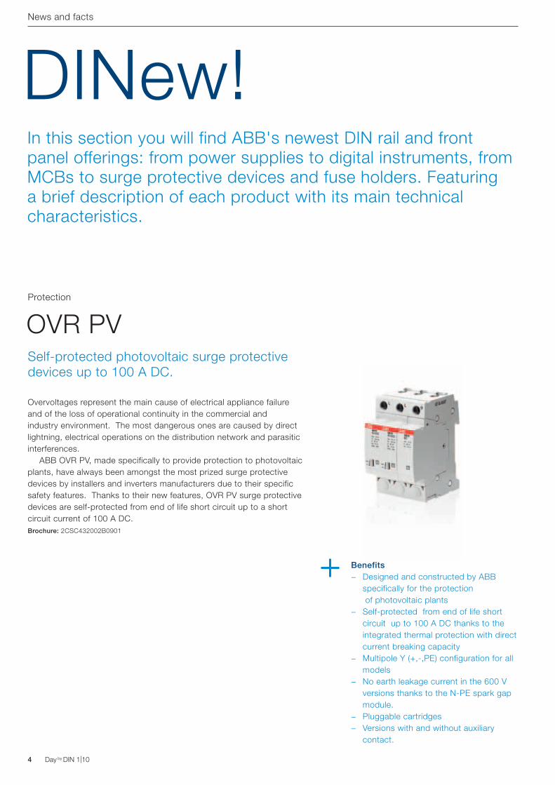
Overvoltages represent the main cause of electrical appliance failure and of the loss of operational continuity in the commercial and industry environment. The most dangerous ones are caused by direct lightning, electrical operations on the distribution network and parasitic interferences. ABB OVR PV, made specifically to provide protection to photovoltaic plants, have always been amongst the most prized surge protective devices by installers and inverters manufacturers due to their specific safety features. Thanks to their new features, OVR PV surge protective devices are self-protected from end of life short circuit up to a short circuit current of 100 A DC.Brochure: 2CSC432002B0901
OVR PVProtection
Self-protected photovoltaic surge protective devices up to 100 A DC.
Benefits − Designed and constructed by ABB
specifically for the protection of photovoltaic plants
− Self-protected from end of life short circuit up to 100 A DC thanks to the integrated thermal protection with direct current breaking capacity
− Multipole Y (+,-,PE) configuration for all models
− No earth leakage current in the 600 V versions thanks to the N-PE spark gap module.
− Pluggable cartridges − Versions with and without auxiliary
contact.

Day by DIN 1|10 5Day by DIN 1|10
News and facts
The range of E 90 fuse holders is rich in devices which provide visual warnings of fuse tripping, for industrial applications and photovoltaic plants: E 90s PV, in particular, is the first modular fuse holder with a signal light with a nominal voltage of up to 1000 V DC. Fuse tripping is easily displayable on the device handle thanks to the special LED display. The visual warning, in red, is activated when the fuse trips, allowing the immediate identification of ther failed line. In the case of battery installation, the failed pole on which to carry out the cartridge replacement is immediately identifiable.Brochure: 2CSC444002B0902
E 90 Fuse holders Protection
Benefits − Designed and manufactured by ABB
specifically for the monitoring of industrial and photovoltaic plants, from 24 to 1000 V
− Easy identification of the faulted pole − Auxilliary power supplies not needed
With blown fuse indication
The TMD-T4/96 temperature control unit now has a completely different look, for total aesthetic uniformity with ABB industrial devices. The control unit takes up to four PT100 temperature probes and allows the monitoring of excessive increases in the temperature of the power transformers: the detection of critical values along with an indication of overload or malfunction, allows the prevention of possible failure and cost-inefficiencies of the installation. Brochure: 2CSC441019B0901
TMD-T4Measurement
Restyling of the TMD-T4/96 temperature control unit
Benefits − Monitoring and management of 4
distinct temperatures to prevent malfunctions and sources of inefficiency
− Double pre-alarm (ALARM) level and tripping (TRIP)
− Serial output RS485, Modbus RTU protocol
− Restyling in line with all ABB industrial products

6 Day by DIN 1|10 Day by DIN 1|10
News and facts
Designed to guarantee maximum functionality and minimum employed space, all the products in the digital instruments range are of a new compact size: only 30 mm of depth inside the switchgear! The new measuring instruments include the features of the traditional instruments and, in addition, they feature an integrated programmable relay. Thanks to the internal programmable relay, it is possible to set tripping threshold alarms of maximum and minimum voltage and current. Moreover, it is possible to visualize the maximum and minimum peak values of the measured parameter. Brochure: 2CSC445018B0902
VLMD P and AMTD PMeasurement
Benefits − Load measurement and management in
a single product − Alarm threshold completely user-
programmable − Visualization of peak values: maximum
and minimum current, and maximum and minimum voltage.
− Suitable both for DC and AC − Optimisation of installation spaces: only
30 mm of depth inside the switchboard
Digital VLMD P and AMTD P instruments for the front panel
The exclusive design of the new D Line digital time switches, with white back-lit LCD display, is combined with an extreme simplicity of use, with two line text menus and only four pushbuttons. Thanks to the innovative management of the holiday periods, the D Line clocks allow the exclusion of the normal weekly program at one or more points in the year or over the years. Brochure: 2CSC440021B0901
D LineControl
Digital time switches
Benefits − High-contrast LCD display, for optimal
visibility in all conditions. − The clock and the internal battery are
activated at first installation − Holiday management at different times
of the year − Minimum change-over switching of 1
second − Maintenance management of the
connected loads − Zero load switching − Running reserve of 6 years from first
power on − Vast choice of programs: standard,
cyclic, random and holiday − Multilanguage menu offers the possibility
of choosing from 11 languages

Day by DIN 1|10 7Day by DIN 1|10
News and facts
The new E 9F series of fuses represent the right solution for protection against overloads and short circuits. The gG types are characterised by a rapid trip curve, ideal for protecting electronic devices, transformers and electrical cables, while the aM types are characterised by a delayed trip curve, that allows the protection of industrial motors that, in start-up mode, call for a high surge of current. Brochure: 2CSC44402B0901
E 9FProtection
Benefits − Nominal voltage from 400 to 690V AC − Nominal currents from 0,5 to 125A − Interruption power of up to 120kA − Compliant to the ROHS directive − LLOYD, NF, and BV approved
Cylindrical fuses
The range of S800PV-M switch disconnectors for photovoltaic plants has been enlarged with a new bipolar 25 A nominal current and a 650 V DC operating voltage product. The devices in the range conform to IEC 60947-3 Standards and therefore guarantee the complete switch disconnection of the DC side of the photovoltaic plant. S802PV-M25, with 650V DC, is a bipolar disconnector (in 3 modules) that can be fed from both sides. It is used as a manoeuvring device for DC side and works in the DC21A voltage category. The disconnectors in the S800PV-M range have interchangeable terminals that allow them to switch from a standard cage terminal configuration to one with an eyelet terminal. Brochure: 2CSC413001B0904
S802PV-M25Control
DC main switch for photovoltaic applications up to 650 V DC
Benefits − Interchangeable terminals − Visualization of the contact status
for each single pole − No restrictions on polarity and direction
of power supply to the cables. − Use category: DC21A − Possiblity of accessorizing with
contacts, reels and a panel-mounted handle.

Gamma di sezionatori e portafusibili E 90Prestazioni senza compromessi
Il giusto clima in cabinaCentralina di misura della temperatura TMD: controllo e sicurezza dei trasformatori di potenza
8 Day by DIN 1|10 Day by DIN 1|10
Intelligent and safe, the E 90 range allows fast, flexible and error-proof installation, and sets a new standard in safety thanks to its exclusive features. Brochure: 2CSC444002B0902
E 90 disconnectors and fuse holders
News and facts
Protection
The TMD temperature control unit allows the monitoring of excessive increases in the temperature of the power transformers, it provides indication of overload or malfunction, preventing possible failure and cost-inefficiencies of the installation.Brochure: 2CSC441019B0901
TMD temperature control unit
Measurement
The right climate in the switchboard
Uncompromising performance
A range of devices proposed by ABB to control electrical appliances based on the needs that arise in every application, improving their use and guaranteeing an efficient use of energy in the residential, commercial and industrial environment.Brochure: 2CSC440020B0901
Time, light, comfort
Control
Solutions for comfort, energy saving and simple automation
In the newsIf you would like information on the latest catalogues published by ABB or on the most recent software made for professionals in the electrical business to help them with their work, this is the section for you! For every “tool” there is a brief description with a cover photo. The documents and software are free to download from the website http://bol.it.abb.com/

(a)
(b)V
t
V
t
(f)50 Hz
A
050
100
150
200250 500
A
050
100
150
200250 500
V
0
8060
40
20
Su misura.Guida pratica alle misure elettriche nei quadri di bassa tensione
Tempo di efficienza.Da ABB i nuovi orologi digitali Linea D. Semplicemente precisi
Sorveglianza assoluta dell’impianto Voltmetri e amperometri con relè di allarme
Day by DIN 1|10 9Day by DIN 1|10
The CT Facile selection software allows the specification of codes and types of current transformers based on the technical characteristics of the main switch. The program requires the installation of Microsoft Access or Access Runtime.Software: 2CSC445040E0901
Among the new features of the software, the possibility to choose surge protections for photovoltaic applications and the possibility to print a personalised solution in just a few clicks. The software requires the installation of Microsoft Access or Access Runtime.Software: 2CSC432010E0902
CT Facile OVR Facile 2
News and facts
Software: Software:
Thanks to the simulator, numerous DMTME digital multimeter functions can be discovered interactively. DMTME are simple but rich in functionalities, suitable for commercial and industrial applications. Software: 2CSC445020E5101
The measurement and monitoring of electrical parameters allow the optimisation of the prevention of failure and the programming of maintenance operations, thanks to an advanced identification of problems that, actually, translates into a higher level of protection not just of the plants but of the facilities connected to them.Brochure: 2CSC445012D0901
D Line is the new range of ABB digital time switches that includes 1 and 2 channel versions, equipped with large capacity internal battery offers the possibility to be able to function during a blackout and an EEPROM permanent data store, that guarantees adherence to the programming and the maintenance of the time and date settings even in case of a power supply failure.Brochure: 2CSC440021B0901
DMTME Demo
Made to measure
D Line digital time switches
Software:
MeasurementControl
DMTME digital multimeter simulators
Practical guide to the electrical measurements in low voltage switchboards
Time efficiency and accuracy
CT current transformers: today even Easier!
Quick product selection software for surge protective devices
ABB digital instruments guarantee measurement precision and ease of use, achieving a systematic surveillance of the plant: it is the same instrument that warns the operator of a situation that requires attention.Brochure: 2CSC445018B0902
Voltmeters and ammeters
Measurement
Complete installation surveillance

10 Day by DIN 1|10 Day by DIN 1|10
Letters from the front (panel)The editor respondsOn this page, professionals can interact with ABB, always with a view to the continuous updating of their professional skills. Your letters or the most frequently asked questions you send to ABB, regarding DIN rail and front panel products, can be found in this section.
Is it possible to feed the LED of an E210 luminous push button with a different voltage from the one used in the controlled circuit? The cabling of this type of product allows it to be independently wired to the push button and the LED. For example, it is possible to use the pushbutton in a 230 V AC circuit and, by choosing the suitable version of indicator light, connect the LED to a 24 V DC power supply. The LEDs, as a matter of fact, are multivoltage and can be fed with 12-48 V AC/DC, 115-250 V AC and 110-220 V DC. The
possibility to double feed allows the status of the piece of equipment to be visualized independently from the presence of voltage in the pushbutton.
At Limone Piemonte, the renowned tourist spot in the province of Cuneo a “Lu Carfat” village was recently created, comprised of more than fifty habitable units, for use as holiday homes, subdivided into elegant low-rise flats and independent chalets with direct access to the ski slopes.
The objective was to create a luxury residence, that guarantees high levels of comfort and safety to its users, with particular attention however, to the energy efficiency of the buildings, achieved by carefully rationalizing all consumption. The central element of this technological approach is a control and technical automation bus system, to KNX International Standard. For the realization of the electrical plant ABB's products were decided on, both for the control and protection of appliances installed in the electrical panels, and the civil series. In each dwelling the
system carries out the most widespread domotic and safety functions, managing, through programmed scenarios, the lighting and thermoregulation. The functional integration between the efficiency of the system in the single dwellings and the efficiency in the wider environment of the village allows the technical team which manages the district to carry out an autonomous and
Case History Cover feature
The expert answers
Send us your thoughts to this e-mail address: [email protected]
secure management, with optimization of time and costs.Moreover, the data for gas, water, heating, and electricity consumption are gathered - via ABB electronic DeltaMeter meters - and transmitted via KNX to the management system of the district.

Day by DIN 1|10 11Day by DIN 1|10
QuizTests for those who are really skilledDo you want to test your competence and relative knowledge on DIN rail and front panel products? On this page, from time to time, questions related to application of apparatus will be put forward, starting from an easier subject and moving on to a more difficult one, to which to reply.
1- EasyIf I read the following values on a multimeter display, such as a DMTME, installed in a single-phase system for direct insertion via a 50/5 A voltage transformer:
Power P = 1 kWEnergy E = 1 kWh
are they coherent consumption values, given a nominal current of In = 50 A, Isec = 5 A, voltage V = 230 V?
AnswerNo, because, in the calculation, as a tranformation ratio the default value of the instrument was used equal to 1
Pincorrect = V · Isec · kTA = 230 x 5 x 1 = 1,15 kW
It is necessary to consider, instead, kTA = In / Isec=10 and you get:
Pcorrect = V · Isec · kCT = 230 x 5 x 10 = 11.5 kW
2- MediumIf I read the following values on a multimeter display, such as a DMTME, installed in a single-phase system for direct insertion via a 50/5 A voltage transformer:
Power P = 57.5 kWEnergy E = 57.5 kWh
are they coherent consumption values, given a nominal current of In = 50 A, Isec = 5 A, voltage V = 230 V?
AnswerFor the calculation, as a transformation ratio, the value kTA = 50 A was used, giving
Pincorrect = V · Isec · kTA = 230 x 5 x 50 = 57.5 kW
The right value to use is, instead, kTA = In / Isec=10:
Pcorrect = V * Isec * kTA = 230 x 5 x 10 = 11.5 kW
3 - DifficultIs it possible to read on the display of a DMTME multimeter the values PF = 0.7 and cos φ = 0.9 for the same appliance?
If so, why?
AnswerYes, because we are in a non-sinusoidal regime, therefore it is correct to find different PF and cos φ values. If we were in a sinusoidal regime we would have to have equal values of the two parameters.
The expert answers

12 Day by DIN 1|10 Day by DIN 1|10
Top fiveA market classification of the top five most interesting products and current ABB suggestions to installers. In this first issue of Day by DIN, we start off with some tips to improve energy efficiency, one of the most talked about subjects at this moment.
News and facts
Compact modular devices, require less space for installation, with a consequent reduction in the size of the parity circuit panel. Easy to assemble, they permit a reduction in labour time and cable length. The use of low consumption LEDs in the signalling lights of the whole series minimizes consumption.
E 210 Series
Used to control lamps from more than one switch, latching relays call for current only during the brief period of the duration of the pulse, without any consumption in the retention phase.
E 250
Latching relaysOn-off switches, pushbuttons and indicator lights
Measuring is the first step to optimizing energy consumption and to scout sources of money savings. Thanks to energy meters it is also possible to record the green energy produced by individuals or industrial power plants that use renewable resources.
ODINsingle
Energy meters

Day by DIN 1|10 13Day by DIN 1|10
The possibility to control the lights based on the level of external brightness and a specific temporal programming allows a better dividing up of energy consumption, activating lighting only when necessary.
TW
Twilight switches
The installation of relay staircase lighting allows the activation of lighting only for the necessary transit time of people in public and private places, avoiding pointless consumption and saving a lot of energy.
E 232
Staircase lighting relay
News and facts
Events
Health Expo International Health and Assistance Exhibition. ABB took part in Bologna's Salone Exposanità last May with the new CLINOS 3000, the communication and signalling system for hospital locations and suchlike, and with the new product line H+Line, specially designed for Group 2 hospital locations, in order to guarantee insulation and avoid the sudden interruption of the energy supply caused by momentary, non-significant faults or by the interference of other medical devices.
ABB will also be present at:
Home&Building Days Verona, 12-13 October 2010. The international two-day Convention and Exhibition dedicated to Domotics and Building Automation.
Safety Fair Milan, 17-19 November 2010. An international event that, for more than 25 years, has been uniting the workers of the sectors of intrusion, fireproofing, passive protection and Home & Building Automation.
Training courses With an even more developed, locally held offer of training, ABB SACE addresses designers, installers, architects, institutions and agencies, offering innovative solutions to the demands of a continuously evolving market.
For more information:http://bol.it.abb

14 Day by DIN 1|10 Day by DIN 1|10
Technical

Day by DIN 1|10 15Day by DIN 1|10
Technical
Insulation monitoringOperational continuity thanks to IT distribution systemsMarco Castoldi: Line Protection Devices - Product Manager - Modular Din Rail Components

16 Day by DIN 1|10 Day by DIN 1|10
Technical
To ensure the continuous operation of electrical equipment, Standard CEI 64-8, “Electrical equipment using
a nominal voltage less than 1,000 V in alternating current and 1,500 V in direct current”, imposes the obligation of protecting the equipment from direct and indirect contacts.
Means of protection Out of all the means of protection singled out by the Standard, only IT distribution systems can guarantee an increased operational continuity in the case of a first earth fault: as a matter of fact, in these systems, the protection switch doesn not intervene, since the fault current is limited by the high insulation impedance. The IT distribution systems are therefore used where the operational continuity is a fundamental prerequisite, to avoid the risks that an interruption of the power supply would carry.
Operational continuity in a hospital location In operating rooms and all group 2 medical locations, the presence of supply is an essential condition for feeding medical appliances and devices on which the patient's life depends. In these contexts it is mandatory to install an IT-M system that guarantees operational continuity over medical activities even in the case of a first earth fault. The IT-M system is an electrical IT distribution system, in which the letter M stands for the specific application in the medical sector. This system is prescribed by Standard CEI 64-8/7-710, that states the characteristics
that the electrical distribution equipment has to have relative to their particular uses (Section 7) and that medical locations have to have (710). The IT-M system is fed by a specific isolating transformer for medical use that has a permanent insulation control device as prescribed by Standard IEC 61557-8. The IT-M operating principle is based on the fact that the circuit fed by the secondary of the insulation transformer is galvanically separate so, at the appearance of a first earth fault due to a defect of the insulators of a user, the current has no option but to continue to flow through the phase conductors. In this situation, the result is that all the electromedical devices keep on working. The IT-M system is not mandatory, but recommended in group 0 and 1 locations, while in group 2 locations it is mandatory in the patient environment, for the sockets and plugs and for fixed handheld appliances. The first earth fault must however be eliminated immediately, since a second earth fault would cause the tripping of the protective devices (thermomagnetic switches), causing an interruption of the power supply. The Standard deems necessary, therefore, the obligation of installing an insulation monitor to signal the detachment of the first earth fault, in such a way as to intervene promptly, before a further fault interrupts the necessary continuous operation of the equipment.
Operational continuity in an industrial environment Even in an industrial and commercial environment the operational continuity 02
01
01 The protection of the direct and indirect contacts is fundamental for ensuring operational continuity.
02 ISOLTESTER is the insulation monitoring device specifically for group 2 medical locations
03 ISL insulation monitoring devices allow the prompt detection of loss of insulation in the cases in which it is necessary to guarantee a continuous power supply even in the presence of a first earth fault.
Day by DIN 1|10 17Day by DIN 1|10
Technical
IT System: An electrical system in which neutral is insulated or earthed via appropriate value impedance (a few hundred ohm in 230÷400 V plants) and the metallic masses are joined, separately or collectively, to an earthing system that is shared or separate from that to which the neutral might be connected.
Insulation monitoring device: Device able to signal the first earth fault, in such a way as to intervene
promptly, before the intervention of the protection devices to interrupt the necessary continuous operation of the plant.
Group 2 medical locations: Medical locations where electromedical devices are used with applied parts destined to be used in intracardiac surgery, surgical operations, or where the patient is subjected to vital treatment where the absence of a power supply could be life threatening.
GlossaryInsulation resistance:
Is the resistance value of the IT circuit in relation to earth. During normal operation it is very high (even a few Mohm), precisely because the IT system is isolated from earth. A low insulation resistance value is, on the contrary, an indication of a dispersion to earth due to a fault. In Group 2 medical locations, Standard CEI 64-8/7-710 assumes there is a fault when the insulation resistance drops below the 50 kohm threshold.
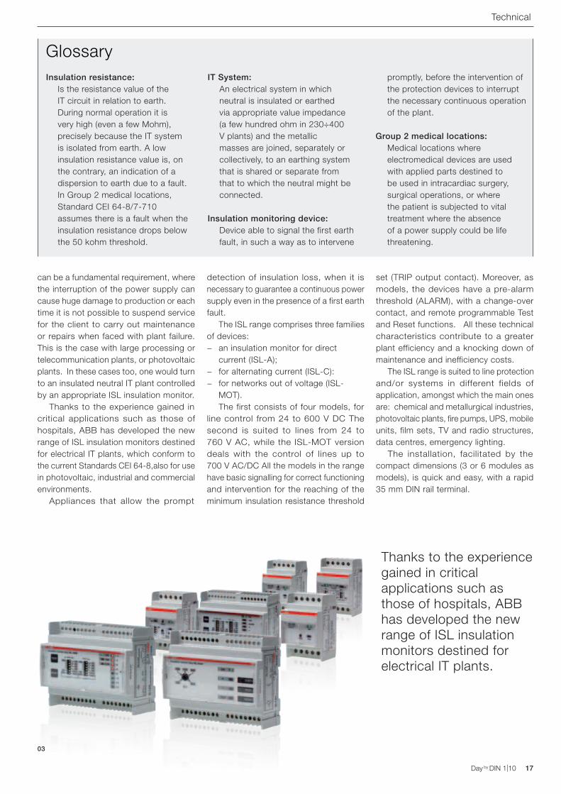
can be a fundamental requirement, where the interruption of the power supply can cause huge damage to production or each time it is not possible to suspend service for the client to carry out maintenance or repairs when faced with plant failure. This is the case with large processing or telecommunication plants, or photovoltaic plants. In these cases too, one would turn to an insulated neutral IT plant controlled by an appropriate ISL insulation monitor. Thanks to the experience gained in critical applications such as those of hospitals, ABB has developed the new range of ISL insulation monitors destined for electrical IT plants, which conform to the current Standards CEI 64-8,also for use in photovoltaic, industrial and commercial environments. Appliances that allow the prompt
03
Thanks to the experience gained in critical applications such as those of hospitals, ABB has developed the new range of ISL insulation monitors destined for electrical IT plants.
detection of insulation loss, when it is necessary to guarantee a continuous power supply even in the presence of a first earth fault. The ISL range comprises three families of devices:
− an insulation monitor for direct current (ISL-A);
− for alternating current (ISL-C): − for networks out of voltage (ISL-
MOT). The first consists of four models, for line control from 24 to 600 V DC The second is suited to lines from 24 to 760 V AC, while the ISL-MOT version deals with the control of lines up to 700 V AC/DC All the models in the range have basic signalling for correct functioning and intervention for the reaching of the minimum insulation resistance threshold
set (TRIP output contact). Moreover, as models, the devices have a pre-alarm threshold (ALARM), with a change-over contact, and remote programmable Test and Reset functions. All these technical characteristics contribute to a greater plant efficiency and a knocking down of maintenance and inefficiency costs. The ISL range is suited to line protection and/or systems in different fields of application, amongst which the main ones are: chemical and metallurgical industries, photovoltaic plants, fire pumps, UPS, mobile units, film sets, TV and radio structures, data centres, emergency lighting. The installation, facilitated by the compact dimensions (3 or 6 modules as models), is quick and easy, with a rapid 35 mm DIN rail terminal.

18 Day by DIN 1|10 Day by DIN 1|10
Technical
The long life of SPDsNominal discharge current In is a measure of the electrical endurance of the SPD. Let's discover why!Emanuele Tosatti: Line Protection Devices - Product Manager - Modular Din Rail Components

Day by DIN 1|10 19Day by DIN 1|10
Technical
We all (or nearly all) know it: a surge protective device is not a fuse, that needs to be changed at the
first tripping, nor a switch, that can be reclosed for an indeterminate number of times once the failure has been eliminated. This small in-depth technical examination aims to give practical tips on how to foresee the duration of a SPD according to its performances.
Standard IEC 61643-11 deems necessary, for the SPD Class 2 tests, a rather articulate functional test. To summarize, we can state that an SPD is made to survive undamaged at least 20 8/20 μs waveform surges to its nominal discharge current In.What is the meaning of this statement in terms of duration of the SPD? Let's look at an example: if the collection area for indirect lightning for a building is, let's assume for simplicity, Am = 1 km2 and, in the district in which this is installed, the number of lightning strikes per year per km 2 is Ng = 4 lightning strikes/km2 x year and the maximum discharge current expected at the plant is 5 kA, a SPD with In = 5 kA will have a duration of approximately:
It is evident that a SPD with In = 5 kA, while fully complying with regulations, would have a very low duration, if compared to the expected life of the plant to which it is connected. If then the SPD are numerous, given that 5 years is the average expected life, the maintenance technician would find himself replacing the cartridges of the SPD even before the theoretical 5 years. The In value which best fits the cost of the SPD with the cost of the successive maintenance of the product lies between 15 kA and 20 kA. We now have the elements to respond to the initial question. Let's imagine the worst case scenario: let's assume that all the discharges that affect the plant in its life are equal to 5 kA, the maximum value forseen by the Standard. So the average number of discharges that the SPD is able to tolerate is shown in table 1, next to the
Glossary
Indirect lightningConsequence of an atmospheric discharge that falls in the vicinity of a building which contains devices.
SPDSurge Protective Device, definition of surge arresters according to International Standards.
Class 2 testTest protocol foreseen by Standard IEC 61643-11 to test products made for protection against indirect lightning.
Nominal discharge current InIt is the 8/20 μs current that the surge protective device is able to discharge to earth at least 20 consecutive times, without deteriorating.
8/20 μs waveIt is the standardized waveform used in the laboratory to simulate the effects of indirect lightning in Class 2 tests. The current reaches 90% of peak value in 8 μs and drops to 50% of this in 20 μs.
Nominal discharge current In of the surge
protective device
Discharge current expected at the plant
65 40 20 15 10 5 2 1
30 1 3 20 50 150 400 2,500 9,000
20 1 5 20 40 200 1,000 3,000
5 1 2 20 150 1,000
blue column. A standard 20 kA SPD for protection, in the most extreme conditions forseen by the Standard of 5 kA surges, will last an average of 200 strikes, presumably more than the average duration of the electrical system in which it is installed!
Table 1
20 surges
Am(km2) ×Ng
surgeskm2year( )
=201× 4
surgessurges year
= 5 years

20 Day by DIN 1|10 Day by DIN 1|10
History

Day by DIN 1|10 21Day by DIN 1|10
History
It was the year 1990.. 5th March to be precise, that for the first time a Law promulgated by the Italian Republic dictated precise rules for the installation of technical appliances in the houses of our Country, rendering compulsory what was already deemed necessary according to technical Standards, in particular Standard CEI 64-8 for everything regarding electrical appliances, and forseeing inspections and penalties on whoever had carried out work that did not comply to rules.
Law 46/90
In reality, already in 1968, Law 186: “Regulations concerning the production of materials, appliances, machinery, electrical and electronic
installations and equipment”, had put into place a first regulation in the safety matters of equipment and, even though it was an important step, it had, however, the defect of not providing for any form of checking. With the promulgation of Law 46/90: “Regulations for the safety of equipment”, the Parliament was finally regulating safety in buildings and not just of buildings. The legislator actually set himself the objective of guaranteeing safety to whoever lived in these dwellings. The situation highlighted by the new Law was disconcerting: in millions of Italian households, appliances, especially electrical ones, did not conform to the design and manufacturing directions set out by the Standard. In other words, they were not safe!
The professionality of the installers recognised Another important innovation introduced by the new Law was represented by the recognition of the professionality of the installers and maintenance technicians. As a matter of fact, previously, anybody, even without specific experience, could undertake the job of installation and maintenance. Now, however, the Law established the obbligation of the possession of precise technical/professional requirements for all those who had various roles in the
realization of a piece of equipment. Requirements that were certified by the attainment of a qualification certificate issued by suitable boards founded by the Chamber of Commerce, that had also to provide to the establishment of the Registers of qualified installers. Fundamental was also the role assigned by the Law to the project for plant installation, transformation, and extension of devices, that had to be the exclusive area of expertise of professionals registered with the professional governing Body and obligatorily written in a suitable article in the cases covered. Finally, to guarantee the production of the plant according to the rules of the trade, the Law ordered the issue of a Declaration of conformity that would have to accompany the appliance for all its life and with which the fitter assumed the responsibility of the correct carrying out of the work. The Declaration of conformity became a necessary document for the issue of the Certificate of habitation, practicability, and, for large structures, also of a Fire Safety Certificate. Law 46/90, with the relative regulation of implementation promulgated in Presidential Decree no. 447 of 6th
December 1991, was abolished in 2008, and replaced by the Ministerial Decree for Economic Development no. 37: “Reorganisation of the provision of installation activities of equipment inside buildings”... but that is another story!
With the promulgation of Law 46/90: “Standards for the safety of equipment”, the Parliament was finally regulating safety in buildings and not just of buildings.

22 Day by DIN 1|10 Day by DIN 1|10
Precision of energy metering
The conformity to the MID Directive ensures the reliability of energy meters
The range of ABB meters conforms to the MID directive, for both single-phase instruments and three-
phase ones. The European Union regulation «Measurement Instrument Directive» MID, published on 30th April 2004 in the Official Journal L. 135 as Directive 2004/22/EC, defines the means of certif ication for an energy meter for fiscal metering purposes. This directive is applicable to the devices and systems with measurement functions defined in the specific attachments. The requirements of the energy meters are defined in attachment MI-003. Before this regulation, the calibration of instruments was subject to national laws. This meant that every device that required calibration could be sold commercially only when a sample of it had obtained national approval and every device had been calibrated. The MID was created as a result of the EU principles that aim to simplify commerce between nations, with the harmonization of demands and the mutual recognition of the declarations of conformity. The MID directive has the intention of regulating the marketing of measuring instruments until the phase when they are actually put into use. The MID regulation includes the following requirements:
− essential requirements for market trading or for putting new devices
into use; − assessment of conformity to the
regulations in force; − procedure for conformity
assessment; − designation criteria of the notification
of a body; − the identification principles of
measuring instruments; − market surveillance.
Nevertheless, the MID does not regulate how the legal check is carried out (calibration service), neither does it regulate the periodic checks of the devices in use, such as, for example: recalibration, lifespan of the calibration or the maximum transaction limits.
Conformity assessment according to the MID directive There are different modules provided for conformity assessment.
Module B Type examination: part of the conformity evaluation procedure, for which a notified body examines the technical design of a measuring instrument and ensures and declares that the technical design corresponds to the appropriate MID Directive requirements.
Technical
01 ODINsingle energy meters for single-phase networks and DELTAplus energy meters for three-phase networks networks, both MID certifiied and suitable for fiscal use
01
Francesca Sassi: Line Protection Devices - Product Manager - Modular Din Rail Components

Day by DIN 1|10 23Day by DIN 1|10
Module D Declaration of type conformity based on the quality assurance of the manufacturing process: part of the conformity evaluation procedure, for which the manufacturer fulfils the obligations defined by the Directive and ensures and declares that the concerned measuring instruments conform to the type described in the EC examination certificate and correspond to the appropriate MID Directive requirements.
Module F Declaration of type conformity based on the verification of the product: part of the conformity evaluation procedure, for which the manufacturer fulfils the obligations defined by the Directive and ensures and declares that the concerned measuring instruments, that have undergone tests and inspections, conform to the type described in the EC examination certificate and correspond to the appropriate MID Directive requirements.
Module H1 Declaration of type conformity based on the complete assurance of quality and control of the design: part of the conformity evaluation procedure, for which
Technical
Product development Modules B + F Modules B + D Modules H1
Development - Planning - Designing Type B examination Type B examination
Inspection of planning
Series production Quality certification system D
Complete quality systemFinished product First calibration F
02
02 Correspondence between the different phases of development of a product and the assessment modules.

24 Day by DIN 1|10
the manufacturer fulfils the obligations defined by the Directive and ensures and declares the worldwide conformity of the concerned instruments to the appropriate requirements of the EU Directive.
Procedure for MID conformity assessment The conformity evaluation of the measuring instruments occurs according to the procedure chosen by the manufacturer. The evaluation criteria regard the three phases for making a product conform, the type of assessment and the notified body. For active electrical energy meters, the manufacturers can choose the assessment modules:
− B + F, applicable to single production batches;
− B + D, applicable to production with the certified quality system ISO 9001.
− H1, applicable to products with their own testing laboratory and certified quality system ISO 9001.
ABB has chosen modules B and D as procedures for the assessment of conformity of their energy meters. The notified body appointed to carry out the conformity test is NMI, a Dutch corporation. The MID covers the bringing of the devices into conformity in terms of development, series production and the finished product; the 02 label establishes the correspondence between the different phases and the assessment modules.
Regulations applicable to electrical energy meters The MID has also redefined the Standards for electrical energy meters
in association with the manufacturers' organisations CITEF and CENELEC (the European Committee for Standardization). The objective was to get the European regulation EN as close as possible to the existing international regulation IEC. Nevertheless, it has been impossible to prevent the arisal of important differences between the EN and IEC regulations.
− designation of class according to EN 50470 with class A, class B, class C;
− designation of class according to IEC 62053 with class 2, class 1, class 0.5.
Marks required for active electrical energy meters In addition to the name of the manufacturer and the name of the product, on active electrical energy meters there must also be an affixed metrology mark to satisfy the MID Directive. The devices must carry the CE mark. Furthermore, a rectangular mark must be applied with a frame containing the letter M, the last two digits of the year of manufacture and, lastly, the identification number of the notified body. The precision class, the unit of measurement and the series number must also be clearly visible (figure 03). Additional information must also appear including the technical characteristics, device outline, number of certification tests and, in the case of electrical meters, the software version. Furthermore, every dispatch of energy meters must be accompanied by the relative declaration of conformity for the EU country concerned. ABB has integrated a declaration of conformity in its instruction and assembly manual.
03
GlossaryActive energy
Quote of available energy to carry out a job
Accuracy classFor a measuring device it is an index of its accuracy.
N. Symbol
1 Type code
2 Voltage range
3 Frequency
4 Base current (max. current)
5 Accuracy class
6 Frequency of impulse signal
7 Frequency LED
8 Series number
9 Week of production
10 Year of production
11 Range of exercise temperature
12 Clock back-up time
13 Protection class
14
MID mark- Safety declaration - Year of verification- Notified body
15 Bar code
16
17 Network type
DAB 130073x57-280/100-500V50/60Hz
1 (6)A CI B (CI.1)Prog Imp/kWh
LED 5000 Imp/kWhTb 72 -40C to 55C
2010 - 33 1001
2CMA139305R1000
0122M10
1 2 3 41716
15 14 13 12 11 10 9 8 7 6 5
03 Example of type of product label, on which all the information regarding the MID mark, the con-ditions of use, and the technical characteristics appear.
Technical

Day by DIN 1|10
CT Facile. The choice of current transformers in 3 clicks
ABB SACE A division of ABB S.p.A. Modular Devices Tel. 02 9034.1 - Fax 02 9034 7609
With a couple of clicks, the CT Facile software allows the pinpointing of a product suitable for the application, just knowing the characteristics of the main switch.http://bol.it.abb.com - www.abb.it

26 Day by DIN 1|10 Day by DIN 1|10
Technical
Day by DIN 1|10 27Day by DIN 1|10
Technical
The switchgear has a peculiarity inside the electrical system: it can actually be considered both as a single unit and as a
more or less complex system, and can therefore simultaneously be subject to the constraints imposed by the legislation in force for matters involving product safety and electrical equipment, as well as the Directive for the free circulation of goods in the Member States of the European Union. Noteworthy, in addition, has been the evolution registered in the design and use of the switchgear over time: from a realization based on the experience of each producer, to the development of standard configurations available in large amounts. A continuous improvement, also from the point of view of safety, that has seen manufacturers and users involved in a close collaboration. Today, the switchgear is not just
enclosure to contain electrical equipment, but a system that integrates the mechanical structure, the distribution systems, and the electrical equipment for protection, control, and signalling, connected to each other to execute the functions required by the electrical plant in which it is housed.
Evolution of the Standard The restructuring plan of the the series of Standard IEC EN 60439 regarding Low voltage Switchgears was started in 1998 with the objective both of having a clearer-cut structure of the Standard and a greater legibility, and of overcoming the difficulty of TTA switchgear definitions (Type-tested low-voltage switchgear and controlgear assembly) and PTTA switchgear (partially type-tested low-voltage switchgear and controlgear assembly) and of their correct interpretation. The journey was not easy, but finally, at the beginning of 2009, the first two parts of the Standard were published,
Low voltage switchgear New Standard EN 61439
The switchgear represents the main human interface for the management, control and distribution of electrical energy
The main new element introduced by Standard IEC EN 61439 is the overriding of the TTA and PTTA definitions and the introduction of the concept of the "verified" switchgear

28 Day by DIN 1|10 Day by DIN 1|10
that modified the "name", assuming the international notation IEC EN 61439, to underline the large change compared to the current series. As regards the application in our Country, in the month of January 2010 the two IEC 61439-1 Standards were published: "General rules" and IEC 61439-2: "Power panels", while the following parts, equivalent to the current ones, will come out in 2012: this entails that, until that date, for the products treated in parts 2, 3, 4 and 5 the reference remains the regulation in force today. And, furthermore, the project of the writing of Guide IEC TR 61439-0 is underway, which will in essence constitute a support to the specification of switchgears in operation, and of installation and performance requirements and, where applicable, a sort of guide to the use of the Standard itself. To be emphasized is how the list of the parts may be expanded to include typologies of electric panels currently excluded: for example, there already exists the proposal for the development of new parts relative to particular switchgears for installation outdoors (campsites, parking lots, docks, etc.).
The applicability of Standard IEC 60439-1 expires on 1st November 2014: until this date, the certificates and the verifications of conformity issued based on this regulation maintain their validity.
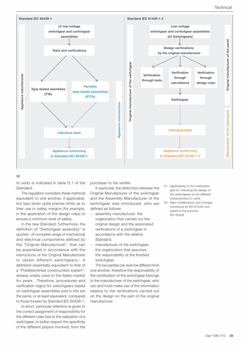
The main changes The main change introduced by Standard IEC 61439 is the overriding of the TTA and PTTA definitions and the introduction of the concept of the "verified" switchgear. The conformity of each switchgear must always be verified by two different routes: verification of the design, to demonstrate that the design of the switchgear conforms to the requirements of IEC 61439; individual verification, to confirm that the materials and the construction are in accordance with what was put forth via the design. While the latter has only been better defined compared to the previous Standard, the design verification uses a new approach, introducing three control methodologies of switchgear design: verification by laboratory tests (equivalent to type tests), verification by calculation/measurement, verification by satisfying design rules. The applicability of these methods to the different characteristics
N° Characteristics to verify Articles or paragraphs
Choice of the viable verification
Verification by trials
Verification by calculations
Verification by design rules
1 Robustness of the materials and parts of the switchgear: 10.2
Resistance to corrosion 10.2.2 YES NO NO
Properties of the insulating materials: 10.2.3
Thermal stability 10.2.3.1 YES NO NO
Resistance of the insulating materials to normal heat 10.2.3.2 YES NO NO
Resistance of the insulating materials to abnormal heat and to fire that starts due to internal influences of an electrical nature
10.2.3.3 YES NO NO
Resistance to ultraviolet radiation (UV) 10.2.4 YES NO NO
Lifting 10.2.4 YES NO NO
Mechanical impact 10.2.6 YES NO NO
Mark 10.2.7 YES NO NO
2 Degree of casing protection 10.3 YES NO YES
3 Insulation distances in air and on surfaces 10.4 YES YES YES
4 Protection against electric shocks and the integrity of the protection circuits:
10.5
Effective operational continuity of the earthing between the earthing of the switchgear and the protection circuit
10.5.2 YES NO NO
Operational continuity of the switchgear during external faults 10.5.3 YES YES YES
5 Installation of manoeuvring devices and components 10.6 NO NO YES
6 Internal electrical circuits and attachments 10.7 NO NO YES
7 Terminals for external conductors 10.8 NO NO YES
8 Dielectric properties: 10.9
Industrial frequency withstand voltage 10.9.2 YES NO NO
Impulse withstand voltage 10.9.3 YES NO YES
9 Overtemperature limits 10.10 YES YES YES
10 Short-circuit withstand 10.11 YES YES YES
11 Electromagnetic Compatibility (EMC) 10.12 YES NO YES
12 Mechanical operation 10.13 YES NO NO
Technical
01
Day by DIN 1|10 29Day by DIN 1|10
to verify is indicated in table D.1 of the Standard. The regulation considers these methods equivalent to one another, if applicable, but lays down quite precise limits as to their use or safety margins (for example, in the application of the design rules) to ensure a minimum level of safety. In the new Standard, furthermore, the definition of "Switchgear assembly" is quoted: «A complete range of mechanical and electrical components defined by the "Original Manufacturer", that can be assembled in accordance with the instructions of the Original Manufacturer to obtain different switchgears». A definition essentially equivalent to that of a “Predetermined constructible system”, already widely used on the Italian market for years. Therefore, procedures and verification logics for switchgears based on switchgear assemblies sold in kits are the same, or at least equivalent, compared to those forseen by Standard IEC 60439-1. In short, particular attention is given to the correct assignment of responsibility for the different roles tied to the realization of a switchgear, to better respect the specificity of the different players involved, from the
purchaser to the verifier. In particular, the distinction between the Original Manufacturer of the switchgear and the Assembly Manufacturer of the switchgear was introduced, who are defined as follows:
− assembly manufacturer: the organization that carried out the original design and the associated verifications of a switchgear in accordance with the relative Standard;
− manufacturer of the switchgear: the organization that assumes the responsibility of the finished switchgear.
The two parties can even be different from one another, therefore the responsibility of the certification of the switchgear belongs to the manufacturer of the switchgear, who can and must make use of the information relative to the verifications carried out on the design on the part of the original manufacturer.
Technical
Tests and verifications
Ap
plia
nce
man
ufa
ctu
rer
Ori
gin
al m
anu
fact
ure
r o
f th
e sw
itch
gea
r
Ori
gin
al m
anu
fact
ure
r o
f th
e p
anel
Ap
plia
nce
man
ufa
ctu
rer
Man
ufa
ctu
rer
of
the
swit
chg
ear
Design verifications
by the original manufacturer
Individual tests
Switchgear
Individual tests
Appliance conforming
to Standard IEC 61439-1-2
Appliance conforming
to Standard IEC 60439-1
Verification
through tests
Verification
through
design rules
Verification
through
calculations
Type-tested asemblies
(TTA)
Partiallly
type-tested assemblies
(PTTA)
Standard IEC 60439-1 Standard IEC 61439-1-2
02
01 Applicability of the methodolo-gies for checking the design of the switchgears to the different characteristics to verify
02 Main modifications and changes introduced by IEC 61439 com-pared to the previous IEC 60439
LV low-voltage
switchgear and controlgear
assemblies
Low-voltage
switchgear and controlgear assemblies
(LV Switchgears)

30 Day by DIN 1|10 Day by DIN 1|10
The expert answers
Do you know that using latching relays instead of contactors in lighting circuits no coil needs to be fed, with a saving of around 2W per relay? The global energy saving for each relay is greater than 5 kWh a year (for an average use of 8 hours a day). The latching relays permit, moreover, the control of the lighting with an unlimited number of pushbuttons. The realization of the circuit with parallel keys is very simple! This makes it particularly suitable to be used in more complex lighting plants, when, for example, the sequential control of the utilities via a single circuit of pushbuttons is required.
These devices can be used to realize innovative solutions, ensuring the maximum saving of energy, thanks to their design philosophy, which consumes only in the brief period of the duration of the impulse control. E250 latching relays allow electrical energy saving and the simplification of the lighting plant cables: fewer cables, less time needed to connect the devices and lower CO2 emissions!
Energy saving ideas E250 latching relays

Day by DIN 1|10 31Day by DIN 1|10
In a control appliance, can I use the two secondary outlets of a single phase transformer to feed two different auxilliary currents? It is possible to simultaneously use both the secondary outlets of an ABB transformer to supply two different low-voltage circuits.
To feed safety extra-low-voltage security circuits (SELV), what type of transformer is needed? To realize a SELV circuit it is necessary to use a safety transformer which conforms to Standard IEC 61558-2-6, that guarantees both the separation between the systems by means of double insulation, and the extra-low voltage required (12÷24 V ±5%).
Is it possible to connect the secondary windings of two or more single-phase ABB transformers in parallel? Up to a maximum of 3 ABB transformers of equal power can be connected in parallel, keeping in mind that the total power which can be drawn will be equal to 90% of the sum of the individual powers. It is necessary to pay maximum attention to the connection of the terminals and, if necessary, test the circuit first in series then in parallel.
In an appliance fed by 24 V AC. I need to supply a cooling fan with a nominal feed voltage of 230 V AC: can I use a transformer, supplying it from the secondary? It is possible to supply the transformers on the secondary side, but due to the nature of their manufacturing, the voltage output from the primary may vary by 10-30% relative to the nominal voltage.
How can I quickly size the power of a transformer? Using the formula
P = 0,8 (∑Pm + ∑Pr + Pa)
where:∑Pm = the sum of all continuous power
consumptions of contactors∑Pr = the sum of all the resistive powersPa = the inrush power of the largest
contactor
Did you know that?
Modular power sockets are also available in various colours
The coloured modular power sockets allow you to signal a specific use of the plug, for example: - green to signal an upstream dedicated
protective device; - red to signal a continuity group, that allows
the use of the socket even in the absence of the mains supply.
There is also the black version, for the connection of industrial and automation devices.
How much does he know?The expert answersThe reliability of ABB's experience in its responses to every need arising from the work of professionals of the sector. In this section an ABB expert responds to the most frequently asked questions that regard the use of DIN rail and front panel products, to resolve problems and propose the most suitable solutions for every application.
The expert answers
32 Day by DIN 1|10 Day by DIN 1|10
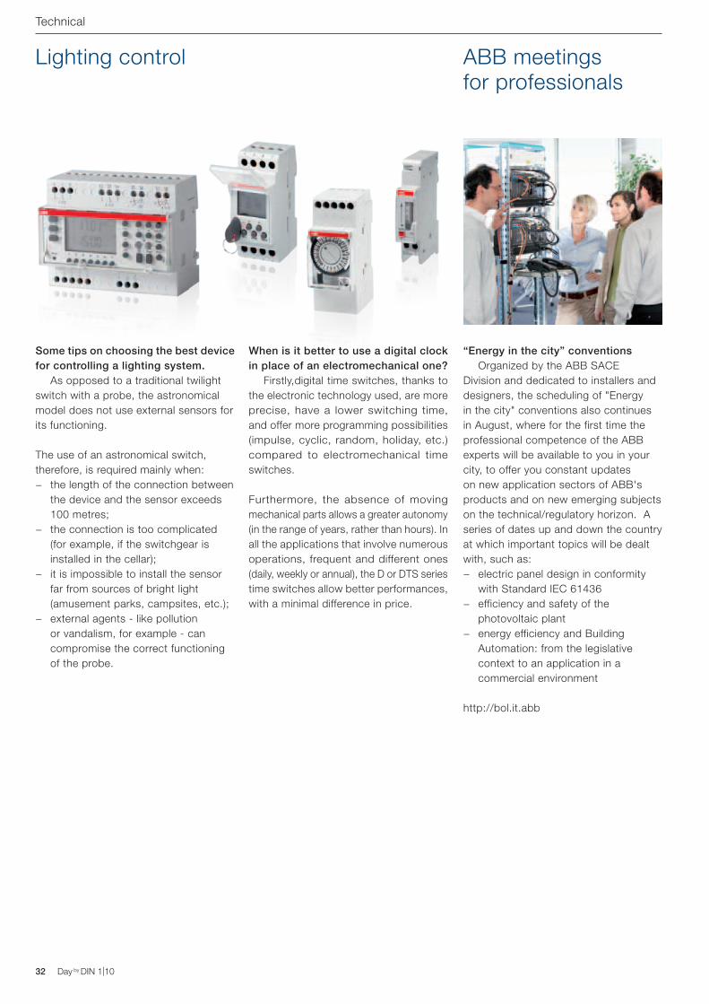
Some tips on choosing the best device for controlling a lighting system. As opposed to a traditional twilight switch with a probe, the astronomical model does not use external sensors for its functioning.
The use of an astronomical switch, therefore, is required mainly when:
− the length of the connection between the device and the sensor exceeds 100 metres;
− the connection is too complicated (for example, if the switchgear is installed in the cellar);
− it is impossible to install the sensor far from sources of bright light (amusement parks, campsites, etc.);
− external agents - like pollution or vandalism, for example - can compromise the correct functioning of the probe.
When is it better to use a digital clock in place of an electromechanical one? Firstly,digital time switches, thanks to the electronic technology used, are more precise, have a lower switching time, and offer more programming possibilities (impulse, cyclic, random, holiday, etc.) compared to electromechanical time switches.
Furthermore, the absence of moving mechanical parts allows a greater autonomy (in the range of years, rather than hours). In all the applications that involve numerous operations, frequent and different ones (daily, weekly or annual), the D or DTS series time switches allow better performances, with a minimal difference in price.
ABB meetings for professionals
Lighting control
“Energy in the city” conventions Organized by the ABB SACE Division and dedicated to installers and designers, the scheduling of "Energy in the city" conventions also continues in August, where for the first time the professional competence of the ABB experts will be available to you in your city, to offer you constant updates on new application sectors of ABB's products and on new emerging subjects on the technical/regulatory horizon. A series of dates up and down the country at which important topics will be dealt with, such as:
− electric panel design in conformity with Standard IEC 61436
− efficiency and safety of the photovoltaic plant
− energy efficiency and Building Automation: from the legislative context to an application in a commercial environment
http://bol.it.abb
Technical

Day by DIN 1|10 33Day by DIN 1|10
DIN Photo
Send the photo of an application you have realized with ABB DIN rail and front panel products to the e-mail address: [email protected] The most interesting and likeable one will be published.
DIN Photo

34 Day by DIN 1|10
15
6
16
2
8
9
3
5
10
1
7
13
4
14
11 12
The Electrical Network The electrical journey for photovoltaic specialists
Across2 – Joining the cable to the module6 – A dark enemy7 – It is of National distribution8 – It turns out better if attention is
paid to..9 – From continuous to alternating11 – Peak power14 – The connection of the modules15 – It can be compulsory or
photovoltaic16 – It is also called a panel
Down1 – This is where you connect the
strings2 – Here are the technical rules of..3 – Better if it is cold4 – The faster it is the cheaper it is 5 – Against overvoltages10 – A synomym of "inclination" in
English11 – They are read on the meter 12 – It can be national, games or solar13 – It manages the incentives14 – Everything starts from there
15
6
16
2
8
9
3
5
10
1
7
13
4
14
11 12
UOE
SR
R
N
O
E
V
N
T
T
T
E
N
E
T
B
DL
R
EM
R
E
O
MC
R
O
R
U
E
P
NMP W TK
TC LT
E S GEA IW E R
OE
O E
ANAS
I
O
QC
SO UD
DNMA
LA
S
OA
NR O SLH
Time to relax
Times have changed!

Day by DIN 1|10
New DS202C. A type of protection that is not afraid of size
ABB SACE A division of ABB S.p.A. Modular Devices Tel. 02 9034.1 - Fax 02 9034 7609
Thanks to the width of only 2 modules the DS202C RCBO series allow a saving of 50% of the space occupied in the switchgears compared to the traditional solution in 4 modules. Available in an advanced and complete technological range, the DS202C can be applied in the commercial sector, large scale industrial plants and naval applications. The new series fits in perfectly with the System pro M compact® modular range, starting with the identical form, that ensures the installation has an aesthetically coordinated appearance. And maximum protection in just 2 modules.http://bol.it.abb.com - www.abb.it
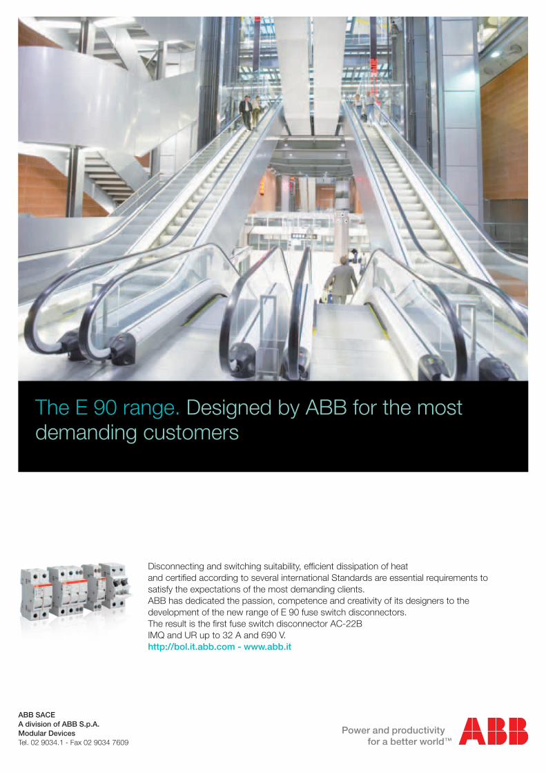
The E 90 range. Designed by ABB for the most demanding customers
ABB SACE A division of ABB S.p.A. Modular Devices Tel. 02 9034.1 - Fax 02 9034 7609
Disconnecting and switching suitability, efficient dissipation of heat and certified according to several international Standards are essential requirements to satisfy the expectations of the most demanding clients. ABB has dedicated the passion, competence and creativity of its designers to the development of the new range of E 90 fuse switch disconnectors. The result is the first fuse switch disconnector AC-22B IMQ and UR up to 32 A and 690 V.http://bol.it.abb.com - www.abb.it