an 1202: low leakage current xgen - excelsys … 1202: low leakage current xgen ... an alternative...
TRANSCRIPT
AN 1202: Low Leakage Current Xgen
Abstract: This application note describes the adjustments that must be carried out on the medical range of Xgen
six-slot powerPacs in order the reduce the leakage current so that two powerPacs can be used in parallel, while
maintaining an EMC performance that complies with the Class A limits of the EN55022 standard.
Electromagnetic Compatibility (EMC)
The electromagnetic compatibility (EMC) of an electrical device is a measure of its ability to function
sufficiently well in its electromagnetic environment without generating unintentional interference to the other
equipment in the system. An interference source may generate conducted or radiated electromagnetic energy,
i.e. conducted emission (CE) or radiated emission (RE). In this application note we will concentrate on
conducted emission.
As well as being obliged to ensure that these electrical devices produce very little electromagnetic disturbances
to their surroundings (emission), according to standards, manufacturers of electrical devices are also obliged to
sufficiently protect their devices from electromagnetic disturbances (immunity). Both of these requirements are
achieved through the use of an electrical filter. X and Y capacitors are frequently used components in electrical
filters.
X and Y Capacitors
There are two forms of possible conducted disturbances, differential mode and common mode.
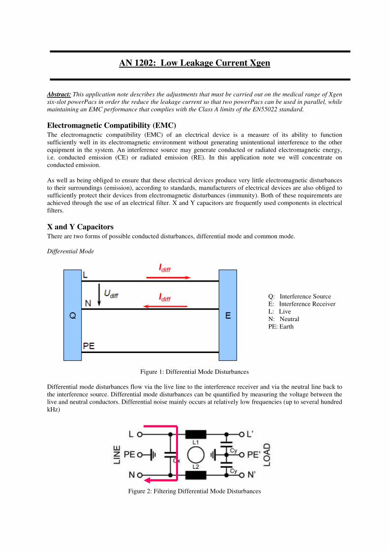
Differential Mode
Q: Interference Source
E: Interference Receiver
L: Live
N: Neutral
PE: Earth
Figure 1: Differential Mode Disturbances
Differential mode disturbances flow via the live line to the interference receiver and via the neutral line back to
the interference source. Differential mode disturbances can be quantified by measuring the voltage between the
live and neutral conductors. Differential noise mainly occurs at relatively low frequencies (up to several hundred
kHz)
Figure 2: Filtering Differential Mode Disturbances
The use X-capacitor (between the live and neutral lines) dampens differential mode disturbances between live
and neutral. It does this by acting as a short circuit for high frequency nioise.
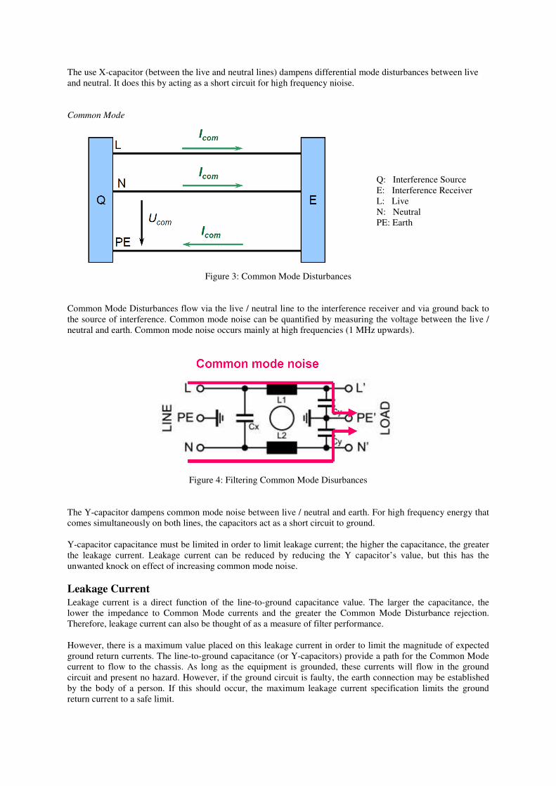
Common Mode
Q: Interference Source
E: Interference Receiver
L: Live
N: Neutral
PE: Earth
Figure 3: Common Mode Disturbances
Common Mode Disturbances flow via the live / neutral line to the interference receiver and via ground back to
the source of interference. Common mode noise can be quantified by measuring the voltage between the live /
neutral and earth. Common mode noise occurs mainly at high frequencies (1 MHz upwards).
Figure 4: Filtering Common Mode Disurbances
The Y-capacitor dampens common mode noise between live / neutral and earth. For high frequency energy that
comes simultaneously on both lines, the capacitors act as a short circuit to ground.
Y-capacitor capacitance must be limited in order to limit leakage current; the higher the capacitance, the greater
the leakage current. Leakage current can be reduced by reducing the Y capacitor’s value, but this has the
unwanted knock on effect of increasing common mode noise.
Leakage Current
Leakage current is a direct function of the line-to-ground capacitance value. The larger the capacitance, the
lower the impedance to Common Mode currents and the greater the Common Mode Disturbance rejection.
Therefore, leakage current can also be thought of as a measure of filter performance.
However, there is a maximum value placed on this leakage current in order to limit the magnitude of expected
ground return currents. The line-to-ground capacitance (or Y-capacitors) provide a path for the Common Mode
current to flow to the chassis. As long as the equipment is grounded, these currents will flow in the ground
circuit and present no hazard. However, if the ground circuit is faulty, the earth connection may be established
by the body of a person. If this should occur, the maximum leakage current specification limits the ground
return current to a safe limit.
The Xgen Power Supply and Leakage Current
With a given supply voltage and frequency, the leakage current depends solely on the capacitors CYL (Live to
Earth) and CYN (Neutral to Earth). The total amount is given by the equation
Ileak = ω CY V
For a filter with a CY of 2.2 nF (Xgen medical power supplies), an input voltage of 230 V at 50 Hz, and
factoring in a tolerance of +/- 20% the expected leakage current can be calculated as:
= 2 * 3.14 * 50 * (2.2 x 10-9
*1.2) * 230
= 190 µA
The medical range of Xgen power supplies has a measured leakage current of around 240 µA. (The limit for
medical power supplies is 300 µA). The additional leakage current can be attributed to stray capacitance
between the Live / Neutral lines and Ground, which acts in parallel to the capacitance of the Y caps. This stray
capacitance is responsible for approximately 50 uA of leakage current.
If we want to use two Xgens in parallel (say in an N+1 redundancy scheme), we must half the leakage current.
We can do this by sufficiently reducing the Y-capacitance (since we cannot adjust the input voltage or
frequency). It should also be remembered that the leakage current due to the stray capacitance will remain the
same. If the Y-capacitors of 2.2 nF are replaced with Y-capacitors of 470 pF, and the calculations repeated, we
get:
Ileak = ω C Y V
= 2 * 3.14 * 50 * (0.47 x 10-9
*1.2) * 230
= 41 uA
Add in the additional 50 µA from the stray capacitance and we would expect a leakage current of around 91 µA.
(Actually measured at 96 uA). Thus, two supplies used in parallel would have a combined leakage of around
180 µA at 230 V, less than the medical standard limit of 300 µA.
But we must remember that reducing the leakage like this will have a knock on effect on the level of common
mode noise.
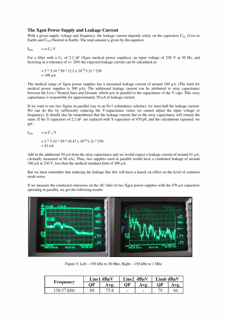
If we measure the conducted emissions on the AC inlet of two Xgen power supplies with the 470 µA capacitors
operating in parallel, we get the following results:
Figure 5: Left – 150 kHz to 30 Mhz, Right – 150 kHz to 1 Mhz
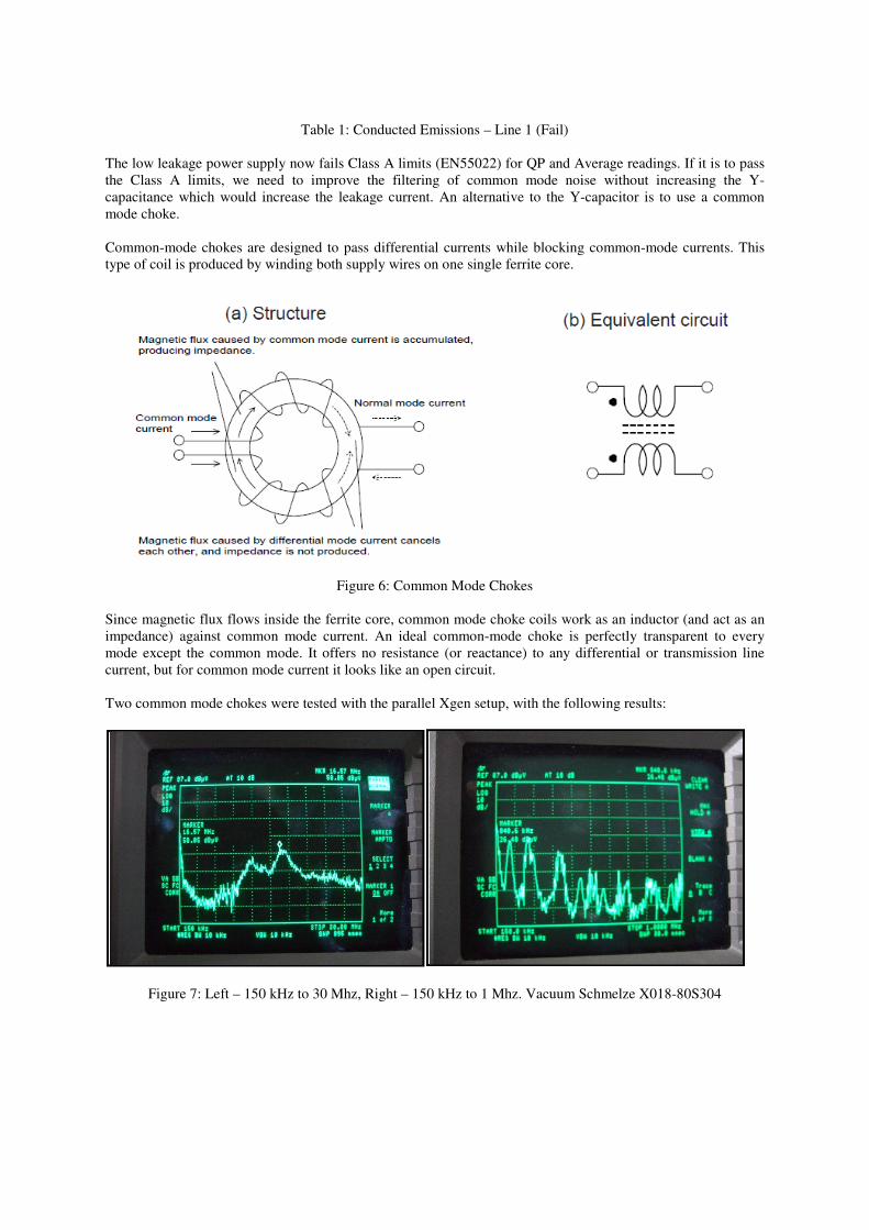
Table 1: Conducted Emissions – Line 1 (Fail)
The low leakage power supply now fails Class A limits (EN55022) for QP and Average readings. If it is to pass
the Class A limits, we need to improve the filtering of common mode noise without increasing the Y-
capacitance which would increase the leakage current. An alternative to the Y-capacitor is to use a common
mode choke.
Common-mode chokes are designed to pass differential currents while blocking common-mode currents. This
type of coil is produced by winding both supply wires on one single ferrite core.
Figure 6: Common Mode Chokes
Since magnetic flux flows inside the ferrite core, common mode choke coils work as an inductor (and act as an
impedance) against common mode current. An ideal common-mode choke is perfectly transparent to every
mode except the common mode. It offers no resistance (or reactance) to any differential or transmission line
current, but for common mode current it looks like an open circuit.
Two common mode chokes were tested with the parallel Xgen setup, with the following results:
Figure 7: Left – 150 kHz to 30 Mhz, Right – 150 kHz to 1 Mhz. Vacuum Schmelze X018-80S304
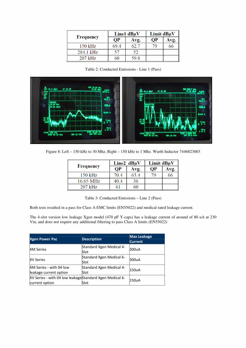
Table 2: Conducted Emissions - Line 1 (Pass)
Figure 8: Left – 150 kHz to 30 Mhz, Right – 150 kHz to 1 Mhz. Wurth Inductor 7446823003
Table 3: Conducted Emissions – Line 2 (Pass)
Both tests resulted in a pass for Class A EMC limits (EN55022) and medical rated leakage current.
The 4-slot version low leakage Xgen model (470 pF Y-caps) has a leakage current of around of 80 uA at 230
Vin, and does not require any additional filtering to pass Class A limits (EN55022)
Xgen Power Pac Description Max Leakage
Current
XM Series Standard Xgen Medical 4-
Slot 300uA
XV Series Standard Xgen Medical 6-
Slot 300uA
XM Series - with 04 low
leakage current option Standard Xgen Medical 4-
Slot 150uA
XV Series - with 04 low leakage
current option Standard Xgen Medical 6-
Slot 150uA
The Excelsys portfolio has a range of products available to the user to provide a solution for whatever the
application requirements may be.
With output power levels from 200W to 1340W, the Xgen series of User configurable modular power supplies
provide high efficiency, high reliability power solutions for Medical, Industrial, Communications and HI-Rel
applications. For more information and copy of our catalogue, please contact [email protected] , or for North
America and Canada [email protected]
Alternatively, please visit our website at www.excelsys.com to download our catalogue and learn more about
the Xgen.
References
[1] Schurter Electronic Components, “Introduction to EMC”, www.schurterinc.com
[2] TE Connectivity, “Understanding Leakage Current”, www.te.com.
[3] Exergia, “Differential and Common Mode Noise”, www.Exergia.info
[4] Chuck Counselman, “Common Mode Chokes”, www.yccc.org
Excelsys Technologies Ltd. is a modern world-class power supplies design company
providing quality products to OEM equipment manufacturers around the world. This is
achieved by combining the latest technology, management methods and total customer
service philosophy with a 20 year tradition of reliable and innovative switch mode power supply design, manufacture and sales. If there are any further points you wish to discuss from this
paper please contact [email protected].