american national standard for machine tools – performance
TRANSCRIPT

ANSI B11.19-2003
American National Standard for Machine Tools –
Performance Criteria for Safeguarding
Secretariat and Accredited Standards Developing Organization: The Association for Manufacturing Technology 7901 Westpark Drive McLean, VA 22102 Approved: APRIL 29, 2003 American National Standards Institute
ANSI Store order #X204842 Downloaded: 8/18/2005 4:52:12 PM ETSingle user license only. Copying and networking prohibited.

AMERICAN NATIONAL STANDARDS By approving this American National Standard, the ANSI Board of Standards Review confirms that the requirements for due process, consensus, balance and openness have been met by AMT – The Association For Manufacturing Technology (the ANSI-accredited standards developing organization). American National Standards are developed through a consensus process. Consensus is established when substantial agreement has been reached by directly and materially affected interests. Substantial agreement means much more than a simple majority, but not necessarily unanimity. Consensus requires that all views and objections be considered, and that a concerted effort be made toward resolution. This process brings together volunteers and/or seeks out the views of persons who have an interest in the topic covered by this publication. While AMT administers the process and establishes procedures to promote fairness in the development of consensus, it does not write the document and it does not independently test, evaluate or verify the accuracy or completeness of any information or the soundness of any judgments contained in its standards or guidelines. American National Standards are promulgated through ANSI for voluntary use; their existence does not in any respect preclude anyone, whether they have approved the standards or not, from manufacturing, marketing, purchasing, or using products, processes, or procedures not conforming to the standards. However, users, distributors, regulatory bodies, certification agencies and others concerned may apply American National Standards as mandatory requirements in commerce and industry. The American National Standards Institute does not develop standards and will in no circumstances give an interpretation of an American National Standard. Moreover, no person shall have the right or authority to issue an interpretation of an American National Standard in the name of the American National Standards Institute. Requests for interpretations should be addressed to the Secretariat (AMT). AMT makes no warranty, either expressed or implied as to the fitness of merchantability or accuracy of the information contained within this standard, and disclaims and makes no warranty that the information in this document will fulfill any of your particular purposes or needs. AMT disclaims liability for any personal injury, property or other damages of any nature whatsoever, whether special, indirect, consequential or compensatory, directly or indirectly resulting from the publication, use of, application or reliance on this document. AMT does not undertake to guarantee the performance of any individual manufacturer or seller’s products or services by virtue of this standard or guide, nor does it take any position with respect to the validity of any patent rights asserted in connection with the items which are mentioned in or are the subject of this document, and AMT disclaims liability for the infringement of any patent resulting from the use of or reliance on this document. Users of this document are expressly advised that determination of the validity of any such patent rights, and the risk of infringement of such rights, is entirely their own responsibility. In publishing or making this document available, AMT is not undertaking to render professional or other services for or on behalf of any person or entity, nor is AMT undertaking to perform any duty owed by any person or entity to someone else. Anyone using this document should rely on his or her own independent judgment, or as appropriate, seek the advice of a competent professional in determining the exercise of reasonable care in any given circumstances. AMT has no power, nor does it undertake to police or enforce conformance to the requirements of this document. AMT does not certify, test or inspect products, designs, or installations for safety or health purposes. Any certification or other statement of conformance to any health or safety-related information in this document shall not be attributable to AMT and is solely the responsibility of the certifier or maker of the statement. NOTICE: This American National Standard may be revised or withdrawn at any time. The procedures of the American National Standards Institute require that action be taken periodically to reaffirm, revise, or withdraw this standard. You may contact the Secretariat for current status information on this, or other B11 standards. Individuals interested in obtaining up-to-date information on standards can access this information at http:\\www.nssn.org (or by contacting ANSI). NSSN - A National Resource for Global Standards, provides a central point to search for standards information from worldwide sources and can connect those who seek standards to those who supply them.
Published by: AMT – The Association For Manufacturing Technology 7901 Westpark Drive, McLean, VA 22102–4269, USA Copyright © 2003 by the Association For Manufacturing Technology All rights reserved. Printed in the United States of America No part of this publication may be reproduced in any form, in an electronic retrieval system or otherwise, without the prior written permission of the publisher.
ii
ANSI Store order #X204842 Downloaded: 8/18/2005 4:52:12 PM ETSingle user license only. Copying and networking prohibited.

Table of Contents Page
FOREWORD.................................................................................................................V
DELEGATE...................................................................................................................V
EXPLANATION OF THE FORMAT OF THIS STANDARD, AND ANSI B11 CONVENTIONS..........................................................................................................VII
1 SCOPE.................................................................................................................... 1
2 NORMATIVE REFERENCES ................................................................................. 1
3 DEFINITIONS.......................................................................................................... 3
4 RESPONSIBILITY .................................................................................................. 9 4.1 SAFEGUARDING SUPPLIER .................................................................................... 9 4.2 SAFEGUARDING USER........................................................................................... 9 4.3 PERSONNEL ...................................................................................................... 10
5 HAZARD CONTROL ............................................................................................ 10
6 GENERAL SAFEGUARDING REQUIREMENTS ................................................ 11 6.1 PERFORMANCE OF THE SAFETY RELATED FUNCTION(S) ......................................... 11 6.2 SAFETY DISTANCE.............................................................................................. 12 6.3 STOPPING PERFORMANCE MONITOR .................................................................... 12
7 GUARDS: FIXED, ADJUSTABLE, AND INTERLOCKED................................... 12 7.1 DESIGN AND CONSTRUCTION............................................................................... 12 7.2 INSTALLATION AND OPERATION............................................................................ 13
8 SAFEGUARDING (PROTECTIVE) DEVICES ...................................................... 15 8.1 MOVABLE BARRIER DEVICES ............................................................................... 15 8.2 PULL BACK (PULL OUT) AND RESTRAINT DEVICES.................................................. 16 8.3 ELECTRO-OPTICAL, RF, AND AREA SCANNING PRESENCE-SENSING SAFEGUARDING
DEVICES ............................................................................................................. 17 8.4 TWO-HAND OPERATING LEVER, TRIP AND CONTROL DEVICES.................................. 22 8.5 SAFETY MAT DEVICES......................................................................................... 25 8.6 SAFETY EDGE DEVICES....................................................................................... 28 8.7 PROBE DETECTION DEVICES................................................................................ 31 8.8 SINGLE CONTROL SAFEGUARDING DEVICES .......................................................... 32
iii
ANSI Store order #X204842 Downloaded: 8/18/2005 4:52:12 PM ETSingle user license only. Copying and networking prohibited.

9 AWARENESS BARRIERS, SIGNALS AND SIGNS............................................. 33 9.1 AWARENESS BARRIERS....................................................................................... 33 9.2 AWARENESS SIGNALS......................................................................................... 34 9.3 AWARENESS (SAFETY) SIGNS.............................................................................. 34
10 SAFEGUARDING METHODS ............................................................................. 34 10.1 SAFE DISTANCE SAFEGUARDING.......................................................................... 35 10.2 SAFE HOLDING SAFEGUARDING ........................................................................... 35 10.3 SAFE OPENING SAFEGUARDING ........................................................................... 36 10.4 OTHER SAFEGUARDING METHODS ....................................................................... 36
11 SAFE WORK PROCEDURES ........................................................................... 36
12 COMPLEMENTARY EQUIPMENT .................................................................... 37 12.1 SAFETY BLOCKS, SLIDE LOCKS, CHAIN LOCKS, LOCKING PINS................................. 37 12.2 WORKHOLDING EQUIPMENT ................................................................................ 38 12.3 ENABLING DEVICES ............................................................................................ 38 12.4 STOPPING PERFORMANCE MONITOR .................................................................... 40 12.5 PROCESS MALFUNCTION, DETECTION AND MONITORING EQUIPMENT ....................... 41 12.6 HAND TOOLS ..................................................................................................... 41 12.7 SAFETY INTERFACE (SAFETY RELAY) MODULES..................................................... 42 12.8 COVERS AND SHIELDS ........................................................................................ 42 12.9 STOP AND EMERGENCY STOP DEVICES................................................................. 42
13 INSPECTION AND MAINTENANCE OF SAFEGUARDING ............................. 42
14 TRAINING ON THE USE OF SAFEGUARDING ............................................... 43
INFORMATIVE ANNEXES
ANNEX A – GUIDANCE IN UNDERSTANDING THE B11 STANDARDS, B11.19 AND B11.TR3...................................................................................................................... 44
ANNEX B – HAZARD LIST FOR SAFEGUARDING.................................................. 45
ANNEX C – PERFORMANCE OF THE SAFETY-RELATED FUNCTION(S)............. 46
ANNEX D – SAFETY DISTANCE............................................................................... 47
ANNEX E - APPLICATIONS AND ATTRIBUTES ...................................................... 56
iv
ANSI Store order #X204842 Downloaded: 8/18/2005 4:52:12 PM ETSingle user license only. Copying and networking prohibited.
American National Standard B11.19–2003
Foreword (This foreword is not part of the requirements of American National Standard B11.19-2003) The primary objective of this standard is to establish the requirements for the design, construction, installation, operation and maintenance of the safeguarding (e.g., guards, safeguarding devices, awareness devices, safeguarding methods and safe work procedures) used to eliminate or control hazards to individuals associated with machine tools. This standard relies on other standards to determine which safeguarding is required or allowed to control identified hazards or hazardous situations, and is intended to be used in conjunction with the ANSI B11 “base” standard for a given machine tool. To accomplish this objective, this standard has established responsibilities for the safeguarding supplier (e.g., manufacturer, rebuilder, installer, integrator and modifier), the user, and individuals in the working environment. The overall goal is to achieve safe work practices and a safe work environment. In addition, this standard includes a comprehensive informative Annex on safety distance, which utilizes the updated Liberty Mutual anthropometric data. The original data, which OSHA (29 CFR 1910.217 Table 0-10) uses to base their safe distance safeguarding, was developed by Liberty Mutual in the 1940s. This data was updated and published in 1995, and used larger anthropometric surveys especially relating to women and minorities. While the data sets are similar, several important modifications to the maximum gap size / minimum distance were suggested, and these modifications have been incorporated (see Table D.1 and Figure D.10, Annex D). The words "safe" and "safety" are not absolutes. Safety begins with good design. While the goal of this standard is to eliminate injuries, this standard recognizes that risk factors cannot practically be reduced to zero in any human activity. This standard is not intended to replace good judgment and personal responsibility. Operator skill, attitude, training, job monotony, fatigue and experience are safety factors that must be considered by the user. Safeguarding and associated equipment technologies are continuously evolving. This standard reflects the most commonly used and time-tested state of the art at the time of its approval. The inclusion or omission of language relative to any evolving technology, either in the requirements or explanatory area of this standard, in no way infers acceptance or rejection of such technologies. Inquiries with respect to the application or the substantive requirements of this standard, and suggestions for its improvement are welcomed, and should be sent to the AMT – The Association For Manufacturing Technology, 7901 Westpark Drive, McLean, Virginia 22102-4269, Attention: B11 Secretariat. This standard was processed and submitted for ANSI approval by the B11 Accredited Standards Committee on Safety Standards for Machine Tools. Committee approval of this standard does not necessarily imply that all committee members voted for its approval. At the time this standard was approved as an American National Standard, the ANSI B11 Accredited Standards Committee was composed of the following member organizations: John W. Russell, PE, CSP Chairman Gary D. Kopps, Vice-Chairman David A. Felinski, Secretary Organizations Represented Name of Representative(s) Delegate Alternate Aerospace Industries Association of America Wil Wood, ARM Robert Eaker, PE, CSP Alliance of American Insurers John Russell, PE, CSP Keith Lessner Aluminum Extruders Council Jeff Dziki Martin Bidwell American Institute of Steel Construction Thomas Schlafly American Society of Safety Engineers Bruce Main, PE, CSP George Karosas, PE, CSP Association For Manufacturing Technology Russell Bensman Can Manufacturers Institute Geoff Cullen Deere and Company Gary D. Kopps Ellen K. Blanshan Forging Industry Association John W. Commet Karen Taylor General Motors Corporation Michael Taubitz
v
ANSI Store order #X204842 Downloaded: 8/18/2005 4:52:12 PM ETSingle user license only. Copying and networking prohibited.

American National Standard B11.19–2003 Graphic & Product Identification Mfgs. Assn. Donald Root Intl. Association of Machinists & Aerospace Workers Jim Soptic Ken Hass Intl. Union, United Automobile, Aerospace and Agricultural Implement Workers of America (UAW)
Jim Howe, CSP Luiz Vazquez
Machinery Dealers National Association John Stencel, III James Heppner, Jr. Metal Building Manufacturers Association Charles M. Stockinger Charles E. Praeger Metal Powder Industries Federation Dennis Cloutier, CSP Donald White National Electrical Manufacturers Association Vincent A. Baclawski Frank Kitzantides National Fluid Power Association June VanPinsker National Institute for Occupational Safety & Health John Etherton, PhD, PE National Tooling and Machining Association Andy Levine Richard R. Walker Precision Metalforming Association Christopher E. Howell Christie Carmigiano Presence Sensing Device Manufacturers Association Jim Kirton Barry Stockton Rubber Manufacturers Association Kim Weber Robert Walker Sheet Metal and Air Conditioning Contractors' National Association
Mike McCullion
Tooling and Manufacturing Association Jeffery W. Hayes Bruce C. Braker Unified Abrasives Manufacturers’ Association, Bonded Division
Charles S. Conant
U.S. Department of the Navy (NAVSEA) Various delegates depending on the Standard At the time this standard was approved, the ANSI B11 ASC B11.19 Subcommittee had the following members who participated in the development of this revision: Barry A. Stockton, High Tech Consulting Chairman David A. Felinski, AMT Secretary
Don Allison, PhD, PE Chris Bacon Jim Barrett, PhD, PE Joe Bode Sam Boytor Mike Carlson Mike Crampton Howard DeWees Steve Dukich Dennis Ebens Mathew F. Einecker, PE John Etherton, PhD, PE George Fargher Roy F. Gottschalk Christine Hansen Michel Houtermans Jim Howe, CSP Jim Kirton Richard Larson Don Lawson Tom Levitt Marshall Lovelace Jose Marsano John Perrotti, III Jack Podojil Tom Polistina Bill Riley Bill Roorda, PE George Schreck Louis Schubert Joe Schultz Chris Soranno Mike Taubitz
Allison Engineering Delphi Automotive Systems Link Systems Industrial Safety Consultant Fox Controls, Inc. Banner Engineering General Motors SICK Inc. Rockwell Automation Rockford Systems Control Reliability Engineering NIOSH Tapeswitch Gottschalk Engineering Associates Underwriters Laboratories TUV UAW International Union ISB Services LARCO/Safety Controls Pilz Automation Safety Levitt & Associates Stuart C. Irby Company TUV Product Service Gordon Engineering Podojil & Associates Tapeswitch U.S. Department Of Navy Alcona Associates Komatsu America Industries Scientific Technologies Larco Safe-T-Sense General Motors
vi
ANSI Store order #X204842 Downloaded: 8/18/2005 4:52:12 PM ETSingle user license only. Copying and networking prohibited.
American National Standard B11.19–2003
Explanation of the format of this standard, and ANSI B11 conventions
This ANSI B11.19 – 2003 American National Standard is divided into parts formerly referred to as sections or chapters and now referred to as clauses in line with the current ANSI style manual. Major divisions of clauses are referred to as subclauses and, when referenced by other text in the standard, are denoted by the subclause number (e.g., see 5.1). The standard uses a two-column format to provide supporting information for requirements. The material in the left column is confined to “Standards Requirements” only, and is so captioned. The right column, captioned "Explanatory Information" contains information that the writing Subcommittee believed would help clarify the requirements of the standard. The Explanatory Information column should not be construed as being a part of the requirements of this American National Standard. As in all American National Standards, the term “SHALL” denotes a requirement that is to be strictly followed in order to conform to this standard; no deviation is permitted. The term “SHOULD” denotes a recommendation, a practice or condition among several alternatives, or a preferred method or course of action. Similarly, the term “CAN” denotes a possibility, ability or capability, whether physical or causal, and the term “MAY” denotes a permissible course of action within the limits of the standard. To achieve uniform interpretation, it is imperative to read and understand the definitions (clause 3) of this standard. B11 conventions: Operating rules (safe practices) are not included in either column of this standard unless they are of such nature as to be vital safety requirements, equal in weight to other requirements, or guides to assist in compliance with the standard. The B11 standards do not use the term “and/or” but instead, the term “OR” is used as an inclusive disjunction, meaning one or the other or both. A distinction between the terms “individual” and “personnel” is drawn. Individual includes personnel (employees, subcontractors, consultants, or other contract workers under the indirect control of the supplier or user) but also encompasses persons who are not under the direct or indirect control of the supplier or user (e.g., visitors, vendors, etc.). Gauge refers to a measuring or testing instrument; gage refers to a limiting device (e.g., backgage). All Annexes are for information purposes only and are not normative parts of the standard. Suggestions for improvement of this standard will be welcome. They should be sent to AMT-The Association For Manufacturing Technology, 7901 Westpark Drive, McLean, VA 22102 - Attention: B11 Secretariat.
vii
ANSI Store order #X204842 Downloaded: 8/18/2005 4:52:12 PM ETSingle user license only. Copying and networking prohibited.

ANSI Store order #X204842 Downloaded: 8/18/2005 4:52:12 PM ETSingle user license only. Copying and networking prohibited.

American National Standard B11.19–2003 Standard Requirements Explanatory Information American National Standard for Machine Tools -
Performance Criteria for Safeguarding
STANDARD REQUIREMENTS
EXPLANATORY INFORMATION (Not part of the requirements of this American National Standard for Machine Tools —- Performance Criteria for Safeguarding ANSI B11.19–2003)
1 Scope
E1 This standard provides performance requirements for the design, construction, installation, operation and maintenance of the safeguarding listed below when applied to machine tools.
a) Guards (see clause 7); b) Safeguarding devices (see clause 8); c) Awareness devices (see clause 9); d) Safeguarding methods (see clause 10); e) Safe work procedures (see clause 11);
The manufacturer or supplier referred to in this standard is the manufacturer or supplier of the safeguarding, not the manufacturer or supplier of the machine tool (see clause 3 definitions of manufacturer and supplier).
This standard does not provide the requirements for the selection of the safeguarding for a particular application.
See the appropriate ANSI B11 machine tool safety standard for the requirements for the selection of safeguarding based on specific applications. Selection of the safeguarding requires task and hazard identification, and the application of risk assessment and risk reduction of the total production system. See ANSI B11.TR3 on risk assessment and risk reduction, and Annex E for additional guidance.
2 Normative references
E2 Informative references The standards below contain provisions that are referenced in this text. This standard is intended to be used in conjunction with these standards. At the time of publication, the editions indicated were valid. All standards are subject to revision, and parties to agreements based on this American National Standard are encouraged to investigate the possibility of applying the most recent editions of the standards indicated.
The standards below contain information and guidance in the implementation of the requirements of this standard or are referenced by other B11 standards. They are included for information only.
ANSI / NFPA 79 -2002 Electrical Standard for Industrial Machinery
ANSI / NFPA 70 – 2002 The National Electrical Code
ANSI Z535.1 – 2002 Safety Color Code
ANSI Z244.1–2003 Control of hazardous energy – Lockout/tagout and alternative methods
ANSI Z535.3 – 2002 Criteria for Safety Symbols
IEC 61496, 1997: Safety of machinery; Electrosensitive protective equipment
ANSI Z535.4 – 2002 Product Safety Signs and Labels
29 CFR 1910.147: Control of hazardous energy (‘lockout/tagout’) (For more info, www.osha.gov )
1
ANSI Store order #X204842 Downloaded: 8/18/2005 4:52:12 PM ETSingle user license only. Copying and networking prohibited.
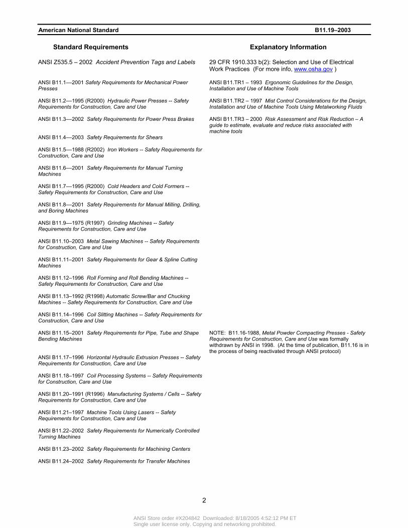
American National Standard B11.19–2003 Standard Requirements Explanatory Information ANSI Z535.5 – 2002 Accident Prevention Tags and Labels
29 CFR 1910.333 b(2): Selection and Use of Electrical Work Practices (For more info, www.osha.gov )
ANSI B11.1––2001 Safety Requirements for Mechanical Power Presses
ANSI B11.TR1 – 1993 Ergonomic Guidelines for the Design, Installation and Use of Machine Tools
ANSI B11.2––1995 (R2000) Hydraulic Power Presses -- Safety Requirements for Construction, Care and Use
ANSI B11.TR2 – 1997 Mist Control Considerations for the Design, Installation and Use of Machine Tools Using Metalworking Fluids
ANSI B11.3––2002 Safety Requirements for Power Press Brakes
ANSI B11.TR3 – 2000 Risk Assessment and Risk Reduction – A guide to estimate, evaluate and reduce risks associated with machine tools
ANSI B11.4––2003 Safety Requirements for Shears
ANSI B11.5––1988 (R2002) Iron Workers -- Safety Requirements for Construction, Care and Use
ANSI B11.6––2001 Safety Requirements for Manual Turning Machines
ANSI B11.7––1995 (R2000) Cold Headers and Cold Formers -- Safety Requirements for Construction, Care and Use
ANSI B11.8––2001 Safety Requirements for Manual Milling, Drilling, and Boring Machines
ANSI B11.9––1975 (R1997) Grinding Machines -- Safety Requirements for Construction, Care and Use
ANSI B11.10–2003 Metal Sawing Machines -- Safety Requirements for Construction, Care and Use
ANSI B11.11–2001 Safety Requirements for Gear & Spline Cutting Machines
ANSI B11.12–1996 Roll Forming and Roll Bending Machines -- Safety Requirements for Construction, Care and Use
ANSI B11.13–1992 (R1998) Automatic Screw/Bar and Chucking Machines -- Safety Requirements for Construction, Care and Use
ANSI B11.14–1996 Coil Slitting Machines -- Safety Requirements for Construction, Care and Use
ANSI B11.15–2001 Safety Requirements for Pipe, Tube and Shape Bending Machines
NOTE: B11.16-1988, Metal Powder Compacting Presses - Safety Requirements for Construction, Care and Use was formally withdrawn by ANSI in 1998. (At the time of publication, B11.16 is in the process of being reactivated through ANSI protocol)
ANSI B11.17–1996 Horizontal Hydraulic Extrusion Presses -- Safety Requirements for Construction, Care and Use
ANSI B11.18–1997 Coil Processing Systems -- Safety Requirements for Construction, Care and Use
ANSI B11.20–1991 (R1996) Manufacturing Systems / Cells -- Safety Requirements for Construction, Care and Use
ANSI B11.21–1997 Machine Tools Using Lasers -- Safety Requirements for Construction, Care and Use
ANSI B11.22–2002 Safety Requirements for Numerically Controlled Turning Machines
ANSI B11.23–2002 Safety Requirements for Machining Centers
ANSI B11.24–2002 Safety Requirements for Transfer Machines
2
ANSI Store order #X204842 Downloaded: 8/18/2005 4:52:12 PM ETSingle user license only. Copying and networking prohibited.
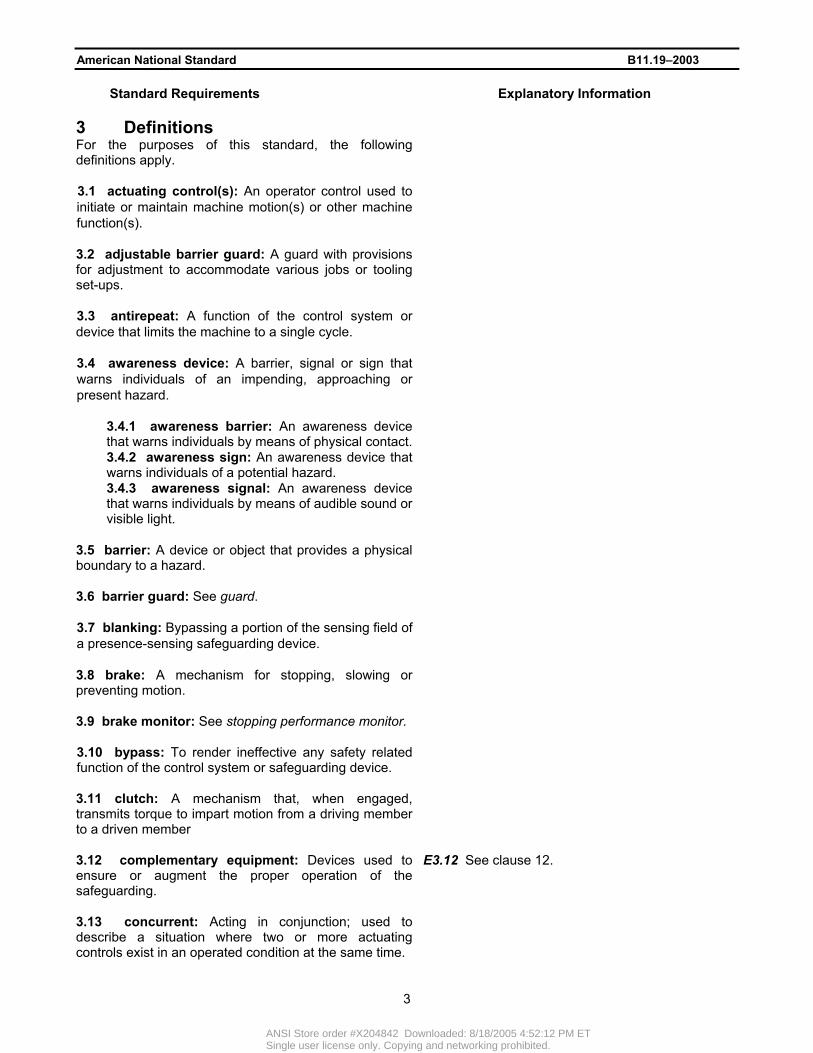
American National Standard B11.19–2003 Standard Requirements Explanatory Information 3 Definitions For the purposes of this standard, the following definitions apply.
3.1 actuating control(s): An operator control used to initiate or maintain machine motion(s) or other machine function(s).
3.2 adjustable barrier guard: A guard with provisions for adjustment to accommodate various jobs or tooling set-ups.
3.3 antirepeat: A function of the control system or device that limits the machine to a single cycle.
3.4 awareness device: A barrier, signal or sign that warns individuals of an impending, approaching or present hazard.
3.4.1 awareness barrier: An awareness device that warns individuals by means of physical contact.
3.4.2 awareness sign: An awareness device that warns individuals of a potential hazard.
3.4.3 awareness signal: An awareness device that warns individuals by means of audible sound or visible light.
3.5 barrier: A device or object that provides a physical boundary to a hazard.
3.6 barrier guard: See guard.
3.7 blanking: Bypassing a portion of the sensing field of a presence-sensing safeguarding device.
3.8 brake: A mechanism for stopping, slowing or preventing motion.
3.9 brake monitor: See stopping performance monitor.
3.10 bypass: To render ineffective any safety related function of the control system or safeguarding device.
3.11 clutch: A mechanism that, when engaged, transmits torque to impart motion from a driving member to a driven member
3.12 complementary equipment: Devices used to ensure or augment the proper operation of the safeguarding.
E3.12 See clause 12.
3.13 concurrent: Acting in conjunction; used to describe a situation where two or more actuating controls exist in an operated condition at the same time.
3
ANSI Store order #X204842 Downloaded: 8/18/2005 4:52:12 PM ETSingle user license only. Copying and networking prohibited.

American National Standard B11.19–2003 Standard Requirements Explanatory Information 3.14 control reliability: The capability of the machine control system, the safeguarding, other control components and related interfacing to achieve a safe state in the event of a failure within their safety related functions.
E3.14 See also, safety related function.
3.15 control system: Sensors, manual input, and mode selection elements, interlocking and decision–making circuitry, and output elements that control the machine operating devices or mechanisms.
3.16 cycle: A complete movement or process from the initial start position or state back to that same start position or state.
E3.16 A cycle may be the motion of the slide of a hydraulic press from open to close to open, the time from loading a workpiece into a milling machine until that part is removed, or a machine sequence without motion.
3.17 design: To develop and plan the machine or safeguarding to meet the intended purpose and function.
3.18 device: A component, attachment or mechanism designed to serve a specific purpose or perform a specific function.
3.19 enabling device: A manually operated device which when continuously activated, permits motion.
3.20 ensure: To design, construct, and apply by the user or supplier or to establish, maintain, or monitor an effective program, procedure, or system to implement the safeguarding or system requirements of this standard.
3.21 foot control: A foot-operated mechanism or device used as an actuating control.
3.22 guard: A barrier that prevents exposure to an identified hazard.
E3.22 Sometimes referred to as “barrier guard.”
3.23 hand control: A hand-operated mechanism or device used as an actuating control.
3.24 hand tool: Any device used for manual feeding or removal of a workpiece, freeing of a jammed workpiece, or removal of scrap.
3.25 hazard: A potential source of harm to individuals.
3.26 hazard area: An area or space that poses an immediate or impending hazard.
3.27 immediate stop command: A command that initiates an action(s) to stop a hazardous motion (or situation) at any point in the machine cycle.
4
ANSI Store order #X204842 Downloaded: 8/18/2005 4:52:12 PM ETSingle user license only. Copying and networking prohibited.

American National Standard B11.19–2003 Standard Requirements Explanatory Information 3.28 individual: A particular human being.
E3.28 For the purposes of this standard, a distinction between individual and personnel is drawn. The term “individual” includes personnel but encompasses persons who are not under direct or indirect control of the supplier or user (e.g., visitors, vendors, etc.). See also, personnel.
3.29 installer: A supplier who installs the safeguarding.
E3.29 See also, supplier.
3.30 integrator: A supplier who applies or installs safeguarding, safety-related control interfaces, interconnections or the safety-related functions of the control system into a machine production system.
E3.30 See also, supplier.
3.31 interlock: An arrangement in which the operation of one control or mechanism allows or prevents machine motion.
3.32 interlocked barrier guard: A barrier, or section of a barrier, interfaced with the machine control system in such a manner as to prevent inadvertent access to the hazard.
3.33 maintenance personnel: Individuals who inspect and maintain the safeguarding.
E3.33 When maintenance personnel perform installation, integration or modification activities, they are considered installers, integrators or modifiers, respectively. See also, the clause 3 definitions of these terms, and 4.1.
3.34 manufacturer: A supplier who designs or manufactures safeguarding.
E3.34 See also, supplier.
3.35 modifier: A supplier who changes the original purpose or function of safeguarding by design or construction.
E3.35 See also, supplier.
3.36 monitoring: The checking of system components to detect a failure of a component, subassembly or module that affects the performance of the safety-related functions.
3.37 movable barrier device: A safeguarding device arranged to enclose the hazard area before machine motion can be initiated.
E3.37 There are two types of movable barrier devices: – Type A, which encloses the hazard area during
the complete machine cycle; – Type B, which encloses the hazard area during
the hazardous portion of the machine cycle.
3.38 muting: The automatic temporary bypassing of any safety related function(s) of the control system or safeguarding device.
5
ANSI Store order #X204842 Downloaded: 8/18/2005 4:52:12 PM ETSingle user license only. Copying and networking prohibited.

American National Standard B11.19–2003 Standard Requirements Explanatory Information 3.39 normal stop command: A command that initiates an action(s) to stop motion(s) or situation(s) at the end of a machine cycle or at other points required by the machine functions.
3.40 operator: An individual who performs production work on the machine and who controls the movements of the machine.
3.41 operator controls: A push button, switch, lever, hand wheel, or other device actuated by the operator that initiates, cycles, controls or stops the motion of a machine.
3.42 personnel: Individuals who are employed by or on behalf of the user.
E3.42 Personnel includes subcontractors, consultants, or other contract workers under the indirect control of the supplier or user.
3.43 point of operation: The location in the machine where the material or workpiece is positioned and work is performed.
3.44 presence-sensing device: A device that creates a sensing field, area or plane to detect the presence of an individual or object.
E3.44 For the purpose of this standard, a presence-sensing device is an electro-optical, radio frequency or area scanning device.
3.45 probe detection device: A device used to detect the presence or absence of the individual’s hand by encircling all or part of the hazard area with a two- or three-dimensional object prior to actuating the machine cycle.
3.46 pull back (pull out) device: A device that is attached to the operator's hands and wrists and is connected to the ram, slide, upper die, or other moving portion of the machine, so that when properly adjusted, the device will prevent the operator from reaching into the hazard area, or withdraw the operator’s hands from the hazard area during hazardous motion.
3.47 rebuilder: A supplier who restores safeguarding to its original design and function.
3.48 redundancy: The use of multiple means to perform the same function.
3.49 repeat: An unintended or unexpected successive cycle of the machine.
E3.49 Typically results from, or in conjunction with, a malfunction.
3.50 restraint device: A safeguarding device with attachments for the operator's hands and wrists that prevents the operator from reaching into the hazard area.
E3.50 Also sometimes referred to as a hold out device.
6
ANSI Store order #X204842 Downloaded: 8/18/2005 4:52:12 PM ETSingle user license only. Copying and networking prohibited.
American National Standard B11.19–2003 Standard Requirements Explanatory Information 3.51 safe holding (workpiece) safeguarding: A method of safeguarding that requires the operator to hold the workpiece with both hands so the hands are out of the hazard area during the hazardous portion of the machine cycle.
3.52 safe opening safeguarding: A method of safeguarding that limits access to the hazard area by the size of openings or by closing off access when the workpiece is in place in the machine.
3.53 safe work procedure(s): Formal written instructions developed by the user, which describe how a task is to be performed.
3.54 safeguarding: Protection of personnel from hazards by the use of guards, safeguarding devices, awareness devices, safeguarding methods, or safe work procedures.
3.55 safeguarding device: A device that detects or prevents inadvertent access to a hazard.
3.56 safeguarding method: Safeguarding implemented to protect individuals from hazards by the physical arrangement of distance, holding, openings, or positioning of the machine or machine production system to ensure that the operator cannot reach the hazard.
E3.56 The phrase “safeguarding by location” is often used to describe these methods.
3.57 safety block: A prop that is inserted between opposing machine or tooling members to prevent closing of machine members or tooling components.
3.58 safety distance: The calculated distance between a hazard and its associated safeguard.
E3.58 See also, Annex D.
3.59 safety edge device: A device, consisting of a sensing edge and its control, that detects an individual(s) when in contact with its sensing edge.
3.60 safety interface module: A device designed to ensure the performance of the safety related function(s).
E3.60 Safety interface modules are also commonly referred to as “safety relay modules.”
3.61 safety mat device: A device, consisting of a sensing surface and control, which detects the presence of individual(s) on its surface.
3.62 safety related function(s): That portion of the control system or safeguarding device that either eliminates exposure to a hazardous situation or reduces exposure to a hazard or hazardous situation to a tolerable level.
7
ANSI Store order #X204842 Downloaded: 8/18/2005 4:52:12 PM ETSingle user license only. Copying and networking prohibited.

American National Standard B11.19–2003 Standard Requirements Explanatory Information 3.63 sensing angle: The angle defining the sensing surface at which the individual will always be detected by the sensing edge.
3.64 set-up: The process of adjusting the machine, and installing or adjusting workholding devices, tooling and safeguarding.
3.65 shield: A barrier used to either keep chips or coolant within the confines of the machine, or to reduce the potential of tooling parts or workpieces from being ejected from the machine.
3.66 single control safeguarding device: A single actuating control used to initiate or maintain machine motion, located at a safe distance from the hazard.
3.67 single cycle (stroke): One complete cycle of the machine from the initial (open) position through the closing or work performing position and a return to the initial position.
3.68 stop command: A command that initiates an action(s) to stop a hazardous motion or remove a hazardous situation.
3.69 stopping performance monitor: A sensor, system, or device used to monitor the stopping performance of the machine.
E3.69 A stopping performance monitor is sometimes referred to as a “brake monitor.”
3.70 supplier: An individual, corporation, partnership or other legal entity or form of business who provides equipment or services.
E3.70 A supplier can be the manufacturer, manufacturer’s agent, representative or distributor, reseller, installer, modifier, rebuilder or integrator who provides equipment or services for the safeguarding associated with the machine. For the purpose of this standard, a supplier provides, or makes available for use, all or part of the safeguarding associated with the machine. When the user provides any of the above services, the user is considered the supplier.
3.71 trip or tripping: The actuation of the machine control or mechanism to initiate the machine cycle.
E3.71 Trip or tripping of the machine control or mechanism is usually the momentary actuation of one or more initiating means to initiate a complete, uninterrupted machine cycle.
3.72 two-hand control device: An actuating control that requires the concurrent use of the operator’s hands to initiate or control machine motion during the hazardous portion of the machine cycle.
E3.72 Two-hand control devices are sometimes referred to as hostage controls.
3.73 two-hand trip device: An actuating control that requires the concurrent use of the operator’s hands to initiate the machine cycle.
8
ANSI Store order #X204842 Downloaded: 8/18/2005 4:52:12 PM ETSingle user license only. Copying and networking prohibited.
American National Standard B11.19–2003 Standard Requirements Explanatory Information 3.74 user: An entity that utilizes machines, systems, and related equipment.
E3.74 When the user manufactures, installs, modifies, rebuilds or integrates the safeguarding, the user is considered the supplier.
3.75 workpiece: Any piece of material placed into the machine for the purpose of having work performed upon it.
4 Responsibility 4.1 Safeguarding supplier 4.1.1 The safeguarding supplier, within the scope of its work activity, shall ensure that safeguarding meets the design, construction, integration and installation requirements of this standard.
E4.1.1 See also, 3.74. If more than one entity is involved in the design, construction, integration or installation, each entity is responsible for the scope of its work activity.
4.1.2 The safeguarding supplier shall furnish documentation as required for the safeguarding, including installation requirements, operating instructions, and maintenance requirements.
E4.1.2 The documentation should include the following, where applicable:
• performance specifications; • electrical or pneumatic schematics and
diagrams; • physical environment for which the device
was designed; • function and location of the operator
controls, indicators, and displays; • schedules for periodic maintenance,
lubrication and inspection; • signs and warnings.
4.2 Safeguarding user 4.2.1 The user shall be responsible for ensuring that safeguarding is provided, integrated, installed, maintained, and used in accordance with the requirements of this standard.
E4.2.1 The user should consider the safeguarding supplier’s performance specifications, schematics, and diagrams, operating and maintenance instructions and warnings when installing, operating, and maintaining the safeguarding. When the user designs, constructs, installs, modifies, or reconstructs the safeguarding, the user is considered to be the supplier. See also, 4.1.
4.2.2 The user shall be responsible for ensuring that supervisors, operators, maintenance, and service personnel are trained in the proper installation, adjustment, operation and maintenance of the safeguarding, within the scope of their work activity.
E4.2.2 The user should direct operators and service personnel to immediately report to supervision, any apparent malfunction or improper operation of the safeguarding systems. The user should consider the safeguarding supplier’s performance specifications, schematics and diagrams, operating and maintenance instructions, and warnings when developing installation and operation procedures or instructions.
9
ANSI Store order #X204842 Downloaded: 8/18/2005 4:52:12 PM ETSingle user license only. Copying and networking prohibited.

American National Standard B11.19–2003 Standard Requirements Explanatory Information
10
4.2.3 The user shall ensure that when any change of the tooling, process or procedures occurs, the safeguarding continues to meet the requirements of this standard and the ANSI B11 ‘base’ standard (the B.11 standard dealing with the specific machine tool), or meets the intent of ANSI B11.TR3.
E4.2.3
Changes in the production system that may affect the safeguarding include, but are not limited to:
• tooling changes; • addition or removal of auxiliary equipment; • modification of the machine; • modification of machine systems; • operating method (program); • change in operating personnel; • adjustment location of safeguarding; • part configuration.
Adjustments to the safeguarding or supplemental safeguarding may be necessary.
4.3 Personnel E4.3 Personnel involved with the installation, operation, or maintenance of the safeguarding shall be responsible for following the training and safety procedures provided by the user in the operation and maintenance of the safeguarding.
The Occupational Safety and Health Act of 1970 − Public Law 91-596, states in Section 5(b) “Each employee shall comply with occupational safety and health standards and all rules, regulations and orders issued pursuant to this Act which are applicable to his own actions and conduct.”
Personnel have a responsibility to avoid the hazards that are identified or known to them, and not intentionally attempt to circumvent the safeguarding.
5 Hazard control
E5 Hazards associated with the use of the safeguarding shall be identified and controlled as part of the overall risk reduction strategy.
The overall hazard identification and risk reduction strategy is identified in each ANSI B11 ‘base’ standard or in B11.TR3. These documents are used to select safeguarding appropriate to the foreseeable tasks and identified hazards. Refer to Annex B for additional information on the hazards associated with safeguarding.
ANSI Store order #X204842 Downloaded: 8/18/2005 4:52:12 PM ETSingle user license only. Copying and networking prohibited.

American National Standard B11.19–2003 Standard Requirements Explanatory Information 6 General safeguarding requirements
Guards, safeguarding devices, awareness devices, safeguarding methods, safe work procedures, and complementary equipment shall meet the requirements of this clause and clauses 7, 8, 9, 10, 11 and 12.
6.1 Performance of the safety related function(s)
E6.1
This subclause shall apply when referenced by other parts of this standard. When a component, module, device or system failure occurs, such that it or a subsequent failure of another component, module, device or system would lead to the inability of the safety-related function(s) to respond to a normal stop command or an immediate stop command, the safety-related function shall: • prevent initiation of hazardous machine motion (or
situation) until the failure is corrected or until the control system is manually reset; or
• initiate an immediate stop command and prevent re-initiation of hazardous machine motion (or situation) until the failure is corrected or until the control system is manually reset; or
• prevent re-initiation of hazardous machine motion (or situation) at the next normal stop command until the failure is corrected or until the control system is manually reset.
Because some failures cannot be detected until the completion of a cycle or a portion of the cycle, loss of safety functions may occur for a portion of the machine cycle. Other failures cannot be detected until a demand is made on the safety-related function. An example of such a safety-related function may be the use of an electro-optical device protecting a hazard area where individuals do not normally enter the area during a normal machine cycle. When a failure is detected, the safety-related function should meet the requirements of this clause.
In the presence of a failure, the user shall be responsible to ensure that repetitive manual reset of the system or device is not used for production operation.
The intention of a manual reset is to encourage the diagnosis of a failed component, subassembly, device or module. A second failure may occur during the diagnostic or troubleshooting process, negating the safety-related function(s). Additional safeguarding should be used to protect individuals during this process.
Control reliability: • is one of the design strategies that may be
used to meet these requirements; • cannot prevent a repeat cycle in the event
of a major mechanical failure or in the presence of multiple simultaneous component failures;
• is not provided by simple redundancy. There must be monitoring to assure that redundancy is maintained.
For further information on the performance of safety-related functions, see Annex C.
11
ANSI Store order #X204842 Downloaded: 8/18/2005 4:52:12 PM ETSingle user license only. Copying and networking prohibited.

American National Standard B11.19–2003 Standard Requirements Explanatory Information 6.2 Safety distance E6.2 When required by this standard, the guard or safeguarding device shall be located at a distance from its associated hazard such that individuals cannot reach the hazard before cessation of hazardous motion (or situation).
Guards and safeguarding devices should be located at a safety distance in accordance with Annex D.
6.3 Stopping performance monitor E6.3 When the stopping time of the machine can change to a point where the calculated safety distance used in locating the safeguarding is no longer met, a stopping performance monitor shall be provided in accordance with 12.4 of this standard. See the “base” B11 machine tool safety standard for specific requirements.
A stopping performance monitor is used to detect when stopping time increases to a point that the safety distance calculated in 6.2 no longer protects the safeguarded individual(s). Driven machines having no clutch in their powertrains and using servo drives, ac or dc drives, or variable speed drives may not require a stopping performance monitor. Failure of these drives is usually catastrophic.
The operating mechanisms (cylinders, valves, hydraulic/pneumatic motors) of hydraulic and pneumatic operated machines may become sticky, sluggish or may wear, affecting the stopping distance. The use of a stopping performance monitor should be evaluated based on the risk assessment.
7 Guards: fixed, adjustable, and interlocked
Fixed, adjustable, and interlocked guards shall meet the applicable requirements of clause 6.
7.1 Design and construction 7.1.1 Material used in the construction of barrier guards shall be of such design and strength as to protect individuals from identified hazards.
7.1.2 Barrier guards shall be free of sharp edges, burrs, slag welds, fasteners, or other hazards that may injure individuals when handling, removing or using the guards or equipment.
7.1.3 The design and construction of the barrier guard shall ensure that individuals cannot reach the hazard by reaching over, under, around, or through the barrier guard.
E7.1.3 Other guards, safety devices or methods may be used in conjunction with barrier guards to accomplish this requirement. The safeguarding supplier should provide instructions to the user for the proper installation and use of the barrier guard. Barrier guard openings should conform to Table D.1 and Figure D.10 (Annex D).
12
ANSI Store order #X204842 Downloaded: 8/18/2005 4:52:12 PM ETSingle user license only. Copying and networking prohibited.

American National Standard B11.19–2003 Standard Requirements Explanatory Information 7.1.4 Barrier guards shall be designed and constructed so as to ensure ease of use.
E7.1.4 Barrier guards that are burdensome (i.e., overly large, heavy or cumbersome) to personnel may discourage proper use.
7.1.5 The guard shall be designed and constructed to provide visibility of the hazard area appropriate to the particular operation.
E7.1.5 Where visibility of the operation is required, appropriate materials and color for the device should be selected. For example: a) the perforated material or wire mesh should
provide adequate open viewing area; b) the color should be darker than the area
observed to enhance visibility.
7.1.6 Interlocked barrier guards shall be designed and constructed to meet the following additional requirements:
E7.1.6 See 7.1.1.
1) Interlock devices used in conjunction with barrier guards shall be specifically designed and constructed for use in safeguarding applications.
1) Some electrical interlock devices increase reliability of operation through the use of positive opening contacts that are forced open by the insertion or removal of the interlock actuator by non-resilient (non-spring) members. There are similar devices available for fluid power interlocking. The use of two interlock devices that are checked by electrical or fluid power circuits for proper operation can also greatly increase the reliability of the interlock function. See also, Annex C.
Interlocks should be designed to discourage the capability to easily bypass the interlock with readily available items such as tape, pieces of metal, screws, tools, etc. Some interlock devices use special keys, trapped keys or actuators that make the interlock more difficult to bypass. There are also interlocking devices that physically obstruct or shield the interlock with the guard open, and others that use electrical, mechanical, magnetic, or optical coding.
2) Handles placed on interlocked barrier guards shall be secured to the guard so as not to create a pinch point between the handles and the guard, frame or machine.
7.2 Installation and operation 7.2.1 Attachment of the barrier guard to the machine or the hazard area shall ensure that individuals cannot reach the hazard by reaching over, under, around, or through the barrier guard.
E7.2.1 Other guards, devices, or methods may be used in conjunction with barrier guards to accomplish this requirement. Barrier guard openings should conform to Table D.1 and Figure D.10 (Annex D).
7.2.2 Adjustable barrier guards shall be adjusted to ensure that individuals cannot reach the hazard by reaching over, under, around or through the guard.
E7.2.2 The adjustment of barrier guards should be checked and readjusted, if necessary, after each set-up or tooling change. See also, 7.1.1.
13
ANSI Store order #X204842 Downloaded: 8/18/2005 4:52:12 PM ETSingle user license only. Copying and networking prohibited.

American National Standard B11.19–2003 Standard Requirements Explanatory Information 7.2.3 Components, subassemblies or modules of the interlock or machine control system shall meet the requirements of 6.1.
7.2.4 The interlocked section of the interlocked barrier guard(s) shall be prevented from opening until hazardous motion has ceased, or shall be located so that an individual cannot reach the hazard before cessation of the hazardous motion when the interlocked section is open.
E7.2.4 Interlocked barrier guards are not intended to be used as a normal stop command. Refer to Annex D on safety distance.
7.2.5 When a machine is modified or relocated, the barrier guard(s) shall be re-evaluated in accordance with clauses 4 and 5 or reinstalled to protect individuals from recognized hazards.
7.2.6 The user shall ensure that barrier guards are installed, maintained, and operated so as to protect against: a) unauthorized adjustment or circumvention; b) hazards between the guard and the moving machine
or tooling parts.
E7.2.6 Guards installed in such a manner that tools are necessary for their adjustment or removal may satisfy this requirement. Training and supervision in the adjustment, maintenance, and operation of the safeguarding are necessary to ensure its proper operation. Examples of some types of fasteners that should not be used are:
• slotted or Phillips head screws; • wing nuts; • magnets; • latches and hasps; • hooks and eyes.
The devices should be checked frequently for proper operation.
c) operation such that when the interlock is opened, re-closing the interlock shall not, in or of itself, cause any hazardous motion of the machine.
c) Restarting the equipment should require a deliberate action, such as reactivating the normal actuating control. Interlocks that serve as a safeguarding means are not, by themselves, always able to protect individuals in the area when jogging or cycling the machine during set-up or maintenance operations. Care should be taken to protect such individuals during these operations.
7.2.7 Visibility of the hazard(s) shall be considered when locating the guard.
E7.2.7 Where visibility of the operation is required, appropriate materials and color for the device should be selected, for example:
• perforated material or wire mesh should provide adequate open area;
• color of the material should be darker than the area observed to enhance visibility.
7.2.8 The user shall ensure that barrier guards that are frequently removed or that have movable or hinged sections are interlocked.
14
ANSI Store order #X204842 Downloaded: 8/18/2005 4:52:12 PM ETSingle user license only. Copying and networking prohibited.

American National Standard B11.19–2003 Standard Requirements Explanatory Information 8 Safeguarding (protective) devices Safeguarding devices shall meet the requirements of clause 6.
8.1 Movable barrier devices 8.1.1 Design and construction 8.1.1.1 Type A: The type A movable barrier device shall be designed and constructed to enclose the hazard area prior to the start of hazardous machine motion, and shall be held closed until the machine has ceased motion and is at its initial starting position. The device shall open or be opened at the end of the machine cycle in order to reset the system before initiation of a subsequent machine cycle.
8.1.1.2 Type B: The type B movable barrier device shall be designed and constructed to enclose the hazard area prior to the start of hazardous motion of the machine and shall be held closed until completion of the hazardous portion of the machine cycle. The device shall open at the completion of hazardous motion and shall reset the system prior to the initiation of a subsequent machine cycle.
8.1.1.3 The initiation of the machine cycle shall require: a) the movable barrier device to be in the closed
position; and b) that the cycle initiation means be actuated.
8.1.1.4 Movable barrier devices shall be designed to be capable of returning to the open position should the device encounter an obstruction while enclosing the hazard area.
8.1.1.5 Components, subassemblies or modules of the device shall meet the requirements of 6.1.
8.1.1.6 Movable barrier devices shall not, in and of themselves, create a hazard.
8.1.1.7 The movable barrier device shall be designed and constructed to provide visibility of the hazard area when it is necessary to view the machine operation.
E8.1.1.7 Where visibility of the operation is required, appropriate materials and color for the device should be selected, for example:
• perforated material or wire mesh should provide adequate open area;
• color of the material should be darker than the area observed to enhance visibility.
8.1.2 Installation, operation and maintenance 8.1.2.1 The user shall ensure that the movable barrier device is installed, maintained, adjusted, and operated in accordance with this standard.
E8.1.2.1 The user should follow the supplier's recommendations for proper operation of the device. The user should direct individuals to immediately report any apparent malfunction or improper operation of the device to a designated person.
15
ANSI Store order #X204842 Downloaded: 8/18/2005 4:52:12 PM ETSingle user license only. Copying and networking prohibited.

American National Standard B11.19–2003 Standard Requirements Explanatory Information 8.1.2.2 Movable barrier devices shall be installed and operated such that individuals cannot reach the hazard by reaching over, under, around, or through the device when in the closed position.
E8.1.2.2 Other guards or devices may be used in conjunction with barrier guards to accomplish this requirement. Device openings should conform to Table D.1, and Figure D.3 ( Annex D).
8.1.2.3 Adjustments of the movable barrier device that affect the operational safety of the machine shall only be performed by authorized individuals.
8.1.2.4 The motion of the movable barrier device shall not, in or of itself, create a hazard while enclosing or exposing the hazard area.
E8.1.2.4 When the device encloses (or exposes) the hazard area, it should not cause injury should it come into contact with individuals.
8.1.2.5 Visibility of the hazard(s) shall be considered when locating the movable barrier device.
E8.1.2.5 When necessary to view the machine operation through the guard, it should be installed to provide visibility of the hazard.
8.2 Pull Back (pull out) and restraint devices 8.2.1 Design and construction 8.2.1.1 The pull back device shall be designed to protect the machine operator by keeping the operator's hands out of the hazard area during the hazardous portion of the machine cycle.
8.2.1.2 The restraint device shall protect the operator by holding the operator's hands away from the hazard area at all times.
8.2.1.3 The safeguarding supplier shall provide instructions with the pull back or restraint device for its proper installation and operation, and establish guidelines for its proper maintenance.
E8.2.1.3 See 4.1.2
8.2.1.4 Pull back and restraint devices shall be provided with hand or wrist attachments for the operator and a means of adjustment to allow for varying locations to the nearest point of operation hazard.
8.2.1.5 Fasteners, pins, and other components used to secure and maintain the setting of the pull back or restraint device shall be applied in such a manner as to minimize loosening, slipping, or failure during operation.
8.2.1.6 The pulling or holding members or cables and the hand or wrist attachments of the device shall be of a substantial material that is flexible, non-stretchable, and will resist wear from abrasion.
8.2.2 Installation, operation and maintenance 8.2.2.1 The user shall ensure that the pull back or restraint device is installed, maintained, adjusted, and used in accordance with the requirements of this standard.
E8.2.2.1 The user should: a) make the supplier’s instructions available to set-
up personnel and operators; b) provide additional instruction relative to the
unique application of the device, if necessary; c) provide training to ensure that the instructions
are understood;
16
ANSI Store order #X204842 Downloaded: 8/18/2005 4:52:12 PM ETSingle user license only. Copying and networking prohibited.
American National Standard B11.19–2003 Standard Requirements Explanatory Information
17
d) provide continuing supervision to ensure that the instructions are followed.
8.2.2.2 If more than one operator is required for a particular operation on the machine, and if the additional operator is exposed to the recognized hazard, then: a) The device shall be designed to protect each
operator; or b) Each operator shall be provided with a separate
device; or c) Additional safeguarding shall be provided to ensure
that individuals who are not safeguarded by the device and who are exposed to the recognized hazard are protected.
8.2.2.3 The user shall ensure that the following conditions are met: a) The hand attachments, including wristlets, snaps
and cables, are used in a manner prescribed by the supplier and required by this standard;
b) Die or tooling set-ups that have bolts, nuts, studs, stops, blow-off tubes, or other objects that protrude from the hazard area shall be protected such that they will not interfere with the normal pulling action of the hand attachments.
8.2.2.4 If gloves are used by the operator, the user shall ensure that the gloves are worn over the hand attachments in a manner such that a glove, if trapped in the machine or tooling, will not prevent the pull back device from removing the operator's hand from the hazard area during the hazardous portion of the machine cycle.
8.2.2.5 The user shall ensure that each pull back or restraint device is inspected, checked, and adjusted:
a) according to the user's established procedures at the start of each operator's shift;
b) following a new die or tooling change or adjustment; and
c) when the operators are changed. All necessary adjustments, maintenance and repairs shall be made and completed before operating the machine.
E8.2.2.5 Special consideration should be given to the point of operation opening before and after the work cycle, since the opening may be reduced on some operations. Also, consideration of the relationship between the workpiece and the tooling, including mal-positioning of the workpiece, should be taken into account when making adjustments.
8.3 Electro-optical, RF, and area scanning presence-sensing safeguarding devices
8.3.1 Design and construction 8.3.1.1 The presence-sensing device shall be designed and constructed to create a field that detects the presence of an individual(s). The presence-sensing device shall not create a hazard in and of itself.
E8.3.1.1 The device should be designed and constructed such that it does not present hazards to individuals from:
• sharp edge or pinch point hazards; • radiated light or energy hazards; • electromagnetic interference hazards; • electrical shock hazards.
ANSI Store order #X204842 Downloaded: 8/18/2005 4:52:12 PM ETSingle user license only. Copying and networking prohibited.

American National Standard B11.19–2003 Standard Requirements Explanatory Information 8.3.1.2 The electro-optical presence-sensing device shall have a minimum object sensitivity such that an obstruction of a same or greater size will always be detected anywhere within its sensing field, regardless of the plane of intrusion.
E8.3.1.2 The presence-sensing device should have a minimum object sensitivity stated by the supplier. For example, an electro-optical device may detect an opaque object with a diameter of 32 mm (1-1/4 inch) anywhere in its sensing field, but allow an obstruction with a diameter of 25 mm (1 inch) to pass undetected at certain points in the field.
8.3.1.3 The device shall not fail to change its output state, if not muted, when it detects the presence of an individual.
E8.3.1.3 Muting may be accomplished by the device, its interface, auxiliary controls, or the machine control system. When the device provides the muting, its output may or may not change state.
8.3.1.4 Adjustment or configuration of presence-sensing devices shall be capable of being supervised by the user.
E8.3.1.4 Methods of meeting this requirement include, but are not limited to, the use of key operated controls or controls located under lockable covers. Adjustments or configuration can include, but are not limited to:
• muting; • blanking; • power adjustments; • sensing field configuration; • reset functions.
8.3.1.5 The presence-sensing device shall incorporate visual means to indicate that the device is detecting an individual within the effective sensing field of the device.
E8.3.1.5 Indicators, (usually red and green), displays or meters should be provided to indicate the status of the device. The visual means may be integral to the device or part of the interface or machine control system. Due to the prevalence of color blindness, methods such as unambiguous positioning, patterning, labeling or flashing of the indicators may be effective in providing the indication required.
8.3.1.6 The presence-sensing device shall have a maximum response time that shall not be affected by object sensitivity or environmental changes. The safeguarding supplier shall provide the maximum response time of the presence-sensing device.
8.3.1.7 The RF (radio frequency) presence-sensing device shall provide means to adjust the sensitivity of the field. The field, once adjusted, shall not decrease in sensitivity below this established level.
8.3.1.8 The electro-optical device shall not be affected by ambient light conditions or by changes in the device light source characteristics, such that an increase in response time or object sensitivity occurs.
E8.3.1.8 When the electro-optical device is exposed to signals from other electro-optical devices or to changes in ambient light commonly associated with windows, light fixtures, skylights, bay doors or work area lights, the response time or object sensitivity should not be adversely affected.
18
ANSI Store order #X204842 Downloaded: 8/18/2005 4:52:12 PM ETSingle user license only. Copying and networking prohibited.

American National Standard B11.19–2003 Standard Requirements Explanatory Information 8.3.1.9 Components, subassemblies or modules of electro-optical, RF, and area scanning presence-sensing safeguarding devices shall be designed and constructed to meet the requirements of 6.1.
8.3.1.10 The area scanning device shall provide a means or operating mode to verify the size, shape, and detection capabilities of the detection area or zone. Information shall be provided by the area scanning device supplier to identify the:
a) maximum safeguarding range; b) minimum object sensitivity within the stated
safeguarding range; c) maximum field of view in degrees; d) tolerance in the range measurement; and e) detection capabilities with respect to the reflectivity
of an object versus the distance to the object.
E8.3.1.10 These devices typically operate on the principle of “diffuse reflectance,” which is a principle of transmitting beam(s) of light to form a detection area or zone. When an object enters the detection area, it reflects the transmitted light back to the device, which then evaluates the object’s position. The amount of reflected light (degree of reflectance in percent) that can be reliably detected typically ranges from 1.8% to over 90% and can be represented graphically by reflectivity versus distance. For more information see IEC 61496 parts 1 and 3.
8.3.2 Installation, operation and maintenance 8.3.2.1 Exposure to the hazard(s) shall not be possible by reaching over, under or around the sensing field of the device. Additional guards or safeguarding devices shall be provided to protect those areas.
E8.3.2.1 The user should select a presence-sensing device adequate to prevent individuals from reaching over, under or around the sensing field during the hazardous portion of the machine cycle. Additional safeguarding may be required in conjunction with the device to meet this requirement.
The effective sensing field shall be of adequate height, width, and depth so that entry of the individual into the hazard area is detected.
If individuals can place themselves between the sensing field and the hazard area, additional safeguarding should be used in conjunction with the device to prevent the individual from exposure to the hazard.
When an individual can pass through the sensing field, see the requirements of 8.3.2.3.
The electro-optical presence-sensing device may fail to detect an individual’s presence due to reflective workpieces or objects in the vicinity of the device. Care should be used to ensure that these reflections do not render the device ineffective.
Some examples of reflective objects include, but are not limited to:
• machine surfaces; • tooling; • work pieces; • hand tools; • auxiliary equipment; • workholding tables and fixtures.
Testing each set-up for minimum object sensitivity
should be done with an appropriate test rod, following the supplier’s recommendation.
19
ANSI Store order #X204842 Downloaded: 8/18/2005 4:52:12 PM ETSingle user license only. Copying and networking prohibited.
American National Standard B11.19–2003 Standard Requirements Explanatory Information Where objects are placed within the defined sensing
field of an area optical laser scanner, care should be taken to ensure that:
a) No shadows exist behind the objects such that the device is rendered ineffective;
b) Removal of the object will not allow undetected access to a hazard area.
The device shall be installed such that it does not create additional hazards.
Some installation hazards include, but are not limited to:
• pinch point hazards created by interference between the device and moving members of the machine;
• tripping hazards; • electrical shock hazards; • overhead or other “strike against” hazards; • thermal hazards.
Where such conditions can exist, additional
safeguarding may be required.
8.3.2.2 The presence-sensing device shall be installed at a location so that the effective sensing field prevents individuals from reaching the hazard(s) during the hazardous portion of the machine cycle.
E8.3.2.2 The safety distance calculation is dependent upon the:
• total response time of the device as stated by the safeguarding supplier;
• response time of the interface; • response time of the control system; • time it takes the machine to stop hazardous
motion; and • depth penetration factor of the device.
See Annex D for the formula(e) to calculate the safety distance.
Radio frequency devices have sensing fields that can vary due to:
• antenna(e) design; • effects of adjacent machinery and equipment;• field sensitivity adjustments; and • environmental factors (such as humidity or
temperature). Before the machine is used for production purposes, the RF device should be checked to ensure that the effective field protects individuals at the safety distance.
8.3.2.3 The presence-sensing device shall protect individuals from hazards by initiating an immediate stop command to the machine control system when the sensing field of the device is interrupted during the hazardous portion of the machine cycle. It shall require re-initiation of the normal actuating means prior to the start or continuation of motion of the machine.
E8.3.2.3
20
ANSI Store order #X204842 Downloaded: 8/18/2005 4:52:12 PM ETSingle user license only. Copying and networking prohibited.

American National Standard B11.19–2003 Standard Requirements Explanatory Information When an individual can pass through the sensing field of the presence-sensing device, the device shall initiate an immediate stop command to the machine control system and shall require that the device or machine control be manually reset before hazardous motion can occur.
The operator should ensure that no individual is in the safeguarded area before re-setting the device or machine control and initiating hazardous motion.
The reset device shall be located outside of the safeguarded area such that it cannot be reached from within the safeguarded area. Reset of the device or machine control shall not occur until verification that the safeguarded area is clear of individuals.
Key lock reset switches located at various positions around the safeguarded area may be one method of accomplishing this requirement.
8.3.2.4 Components, subassemblies or modules of the interface or machine control system shall meet the requirements of 6.1.
8.3.2.5 Muting of the device shall be permitted during the non-hazardous portion of the machine cycle. Muting of the device shall be accomplished such that a single failure of a component, a subassembly or a module of the system / device that affects the performance of the safety-related functions shall not prevent a normal stop command from being initiated, or shall cause an immediate stop command. In the event of a failure, re-initiation of the machine shall be prevented until the failure is corrected or the system or device is manually reset.
E8.3.2.5 Muting is typically accomplished by interface circuits or auxiliary controls. The muting element should incorporate a similar level of control reliability as the presence-sensing device itself. A simple cam-operated limit switch wired in parallel with the device’s output is inadequate, as its failure can remain undetected.
In the presence of a failure, repetitive manual reset of the system or device shall not be used for production.
The intention of a manual reset is to encourage the diagnosis of a failed component, subassembly, device or module. A second failure may occur during the diagnostic or troubleshooting process, negating the safety function(s). Additional safeguarding should be used to protect individuals during this process.
See the definition for control reliability and Annex C for further information.
If the machine has reversing capability where a muting hazard is possible, the control system shall include an automatic means so muting is only permitted in the forward direction. If an individual can pass through a sensing field when the device is muted, means shall be provided to ensure that the individual is outside of the hazard area, or that the machine ceases hazardous motion when the muting is removed.
One method of meeting this requirement is by the use of a control circuit interlock on the drive motor starter (forward direction contact) to allow "muting" only in the forward direction, when the starter is energized. See 8.3.2.1
8.3.2.6 Bypassing of the device shall be capable of being supervised by the user. Indication that the device is active or bypassed shall be provided and shall be readily observable by individuals protected by the device.
E8.3.2.6 Care should be taken to ensure that the operators and other individuals are aware that the device has been bypassed so that individuals do not assume that the device is active and they are safeguarded when in fact, the device is bypassed.
21
ANSI Store order #X204842 Downloaded: 8/18/2005 4:52:12 PM ETSingle user license only. Copying and networking prohibited.

American National Standard B11.19–2003 Standard Requirements Explanatory Information When bypassed, the device, interface or control system shall not indicate any state other than “bypass.”
An amber indicator lamp or other means may be used to meet this requirement.
When the device is bypassed, other safeguarding must be provided and used.
When bypassed, the device’s normal status indicators can be misleading if still active. One method that may be used to meet this requirement is to remove power to the device or to disable the normal status indicators when it is bypassed or not being used.
Due to the prevalence of color blindness, methods such as unambiguous positioning, patterning, labeling or flashing of the indicators may be effective in providing the indication required.
8.3.2.7 The radio frequency device shall not be adversely affected by changes around the machine that may alter the sensitivity of the device such that individuals are no longer detected in the sensing field at the proper safety distance.
E8.3.2.7 The radio frequency device may be affected by changes in the conditions around the machine such as ambient conditions, the placement of parts and tote boxes, grounding conditions of the operator, or the movement of industrial trucks. These changes should not adversely affect the performance of the device.
8.3.2.8 The total tolerance in the range measurement of an area scanning device shall be included in determining the distance from the nearest recognized hazard to the detection area or zone. This detection area shall be identified and tested to ensure that the device is able to detect individuals entering the detection area. The effective sensing field shall be verified for proper size and coverage upon installation, replacement, or changes of the detection area.
E8.3.2.8 When the device is horizontally mounted, the detection area or zone should be visibly marked on the floor. This verification can be accomplished by using a programming device or by physically identifying the perimeter of the detection area with an appropriate test rod, following the supplier’s recommendation. This verification is to ensure that a pre-programmed device with a small or improper detection area is not used by mistake in an installation requiring a larger field.
Area scanners may not be suitable (effective) safeguards when used to protect an individual’s hands or fingers from hazards. Items which can affect this suitability are:
• response time; • minimum object sensitivity; • measurement accuracy.
8.4 Two-hand operating lever, trip and control devices
When these devices are not being used for safeguarding, this subclause does not apply.
8.4.1 Design and construction The safeguarding supplier shall be responsible for meeting the requirements of this subclause. See also, 4.1.
E8.4.1 A supplier can be the manufacturer, manufacturer’s agent, representative or distributor, reseller, installer, modifier, rebuilder or integrator who provides equipment or services for the safeguarding associated with the machine.
22
ANSI Store order #X204842 Downloaded: 8/18/2005 4:52:12 PM ETSingle user license only. Copying and networking prohibited.

American National Standard B11.19–2003 Standard Requirements Explanatory Information When the user provides any of the above services,
the user is considered the supplier.
8.4.1.1 Two-hand operating lever devices Two-hand operating levers shall be designed and constructed to protect against unintended or inadvertent cycling of the machine.
E8.4.1.1 The design of the two-hand operating lever device should be such that the operator cannot operate the two levers by the use of one hand and the elbow (or other portion) of the same arm.
The two-hand operating levers shall be designed and constructed to require concurrent operation of both operating levers to cycle the machine. If more than one pair of levers is to be provided, each pair shall be interlocked such that the concurrent operation of all levers is required to cycle the machine. The two-hand operating lever device shall have the individual operator's hand controls arranged by design, construction, or separation to require the use of both hands to trip the machine.
8.4.1.2 Two-hand trip devices Each two-hand trip device shall be designed and constructed to protect each hand trip control against unintended or inadvertent operation.
E8.4.1.2 Protecting the two-hand trip against unintended or inadvertent operation is usually accomplished by the use of ring or palm guards or other fabricated shields.
The two-hand trip device shall have the individual hand controls arranged by design, construction, or separation to require the use of both hands for actuation.
The design or installation of the operator control should be such that the operator cannot operate the two controls by the use of one hand and an elbow (or other portion) of the same arm.
The two-hand trip device shall be designed and constructed to require concurrent operation of both hand trip controls to initiate the machine cycle.
When used in single cycle mode, the two-hand trip function shall incorporate an antirepeat feature.
Characteristics of the total system of the two-hand trip and the drive or clutch mechanism may be combined to achieve antirepeat; that is, while the single-cycle limiting requirement may be achieved by the single-cycle mechanism in the clutch, the two-hand trip should have a feature that requires release of all operating mechanisms (e.g., buttons, valves, or Ievers) before another cycle or stroke can be initiated.
If more than one operator is to be safeguarded by the use of two-hand trip devices, each operator shall have individual hand trip controls. Additionally, all individual hand trip operator controls shall be concurrently operated before the machine is tripped. Means shall be provided to indicate to the operator that the two-hand trip device is selected or de-selected.
The selection of the hand trip control station shall be capable of being supervised by the user.
A key selector switch is sometimes used to supervise the use of each operator control station.
23
ANSI Store order #X204842 Downloaded: 8/18/2005 4:52:12 PM ETSingle user license only. Copying and networking prohibited.

American National Standard B11.19–2003 Standard Requirements Explanatory Information The control system or mechanism shall be designed and constructed so as to prevent cycling of the machine if all operator stations are deselected.
The two-hand trip device shall be designed and constructed to require the release of all hand trip operator controls and the re-actuation of all actuating controls before a machine cycle can be reinitiated.
Components, subassemblies or modules of the device shall meet the requirements of 6.1.
8.4.1.3 Two-hand control devices The two-hand control device shall have individual hand controls arranged by design, construction, or separation to require the use of both hand controls for actuation.
E8.4.1.3
The two-hand control device shall be designed and constructed to protect each hand control against unintended or inadvertent actuation.
Protecting the two-hand control against unintended or inadvertent operation is usually accomplished by the use of ring or palm guards or other fabricated shields.
The two-hand control device shall require the concurrent actuation of both hand controls within a certain time limit before initiating hazardous motion.
ANSI / NFPA 79 and other standards require that the time limit be 500ms or less.
Release of either hand control during the hazardous portion of the machine cycle shall initiate a stop command. Release and reactivation of both hand controls is required before motion is reinitiated.
Components, subassemblies or modules of the device shall meet the requirements of 6.1.
8.4.2 Installation, operation and maintenance 8.4.2.1 It shall be the responsibility of the user to ensure that the two-hand operating Iever, trip, or control device is installed, operated, and maintained in accordance with this standard.
8.4.2.2 The device shall be located at a distance from the nearest hazard such that the operator cannot reach the hazard before cessation of hazardous motion, in accordance with 6.2. The two-hand operating lever, trip, or control device shall require concurrent actuation of both of the operating levers or hand controls to initiate a machine cycle.
8.4.2.3 The two-hand control device shall require the concurrent actuation of the operator's hand controls during the hazardous portion of the machine cycle such that the operator cannot reach the hazard before the hazardous motion has ceased.
24
ANSI Store order #X204842 Downloaded: 8/18/2005 4:52:12 PM ETSingle user license only. Copying and networking prohibited.

American National Standard B11.19–2003 Standard Requirements Explanatory Information 8.4.2.4 If more than one operator is to be safeguarded by the use of two-hand trip or two-hand control devices, each operator shall have individual hand controls. The selection of the two-hand operator control station shall be capable of being supervised by the user. Additionally, each selected two-hand control station shall be concurrently operated and shall require the release of all selected hand controls and the reactivation of all operator's hand controls before a machine cycle can be initiated. Means shall be provided to indicate to each operator that the hand control is selected or de-selected.
8.4.2.5 Components, subassemblies or modules of the interface or machine control system shall meet the requirements of 6.1.
8.5 Safety mat devices 8.5.1 Design and construction The safeguarding supplier shall be responsible for meeting the requirements of this subclause. See also, 4.1.
E8.5.1 A supplier can be the manufacturer, manufacturer’s agent, representative or distributor, reseller, installer, modifier, rebuilder or integrator who provides equipment or services for the safeguarding associated with the machine. When the user provides any of the above services, the user is considered the supplier.
8.5.1.1 Safety mat devices, including multiple mats combined to form one sensing surface, shall be designed and constructed to detect the presence of individuals on its sensing surface.
E8.5.1.1 A safety mat device should have a minimum object sensitivity which detects a 30 kg (66 lbs) weight on an 80 mm (3 1/8 in) disc anywhere on the mat sensing surface, including the area where mats are joined to form a single sensing surface. In some industrial settings, values other than those suggested above may be used when justified.
The device shall not fail to change its output state, if not muted, when it detects the presence of an individual.
Muting may be accomplished by the safety mat device, its interface, auxiliary controls, or the machine control system. When the safety mat device provides the muting, its output may or may not change state.
8.5.1.2 The safety mat device shall not create a hazard in and of itself.
E8.5.1.2 The safety mat device should be designed and constructed such that it does not present hazards to individuals from:
• sharp edges; • slipping or tripping hazards; • electromagnetic interference hazards; • electrical shock hazards.
25
ANSI Store order #X204842 Downloaded: 8/18/2005 4:52:12 PM ETSingle user license only. Copying and networking prohibited.

American National Standard B11.19–2003 Standard Requirements Explanatory Information 8.5.1.3 The safety mat device shall incorporate visual means to indicate that the device is detecting the presence of an individual on the sensing surface of the mat.
E8.5.1.3 Indicator lamps, usually red and green, should be provided to indicate that the safety mat device is functioning. If a bypass is provided, an amber light or other means should be used to indicate that the safety mat device is bypassed. The lights may be integral to the safety mat device, or part of the interface or machine control system. Due to the prevalence of color blindness, methods such as unambiguous positioning, patterning, labeling or flashing of the indicators may be effective in providing the indication required.
8.5.1.4 The safety mat device shall have a maximum response time that shall not be affected by object sensitivity adjustments or environmental changes.
E8.5.1.4 The safeguarding supplier should state the maximum total response time, including output devices, of the safety mat device.
8.5.1.5 Components, subassemblies or modules of the device shall meet the requirements of 6.1.
8.5.2 Installation, operation and maintenance 8.5.2.1 Adjustment or configuration of safety mat devices shall be capable of being supervised by the user.
E8.5.2.1 Methods of meeting this requirement include, but are not limited to, the use of key operated controls or controls located under lockable covers. Adjustment or configuration can include, but is not limited to:
• muting; • mat configuration; • reset functions; • sensitivity adjustments.
8.5.2.2 Exposure to the hazard(s) shall not be possible by reaching over, under or around the sensing surface of the device. Additional guards or safeguarding devices shall be provided to protect those areas.
E8.5.2.2 The user should select a safety mat device adequate to prevent individuals from reaching over, under or around the sensing surface during the hazardous portion of the machine cycle. Additional safeguarding may be required in conjunction with the device to accomplish this requirement.
The effective sensing surface shall be of adequate width and length so that an individual’s entry into the hazard area is detected.
If individuals can place themselves between the sensing surface and the hazard area, additional safeguarding should be used in conjunction with the device to prevent the individual from exposure to a hazard. When an individual can cross over the mat surface, see 8.5.2.4.
The safety mat device shall not create a hazard in and of itself.
Some installation hazards include, but are not limited to:
• sharp edges; • slipping or tripping hazards; • electromagnetic interference hazards; • electrical shock hazards.
26
ANSI Store order #X204842 Downloaded: 8/18/2005 4:52:12 PM ETSingle user license only. Copying and networking prohibited.

American National Standard B11.19–2003 Standard Requirements Explanatory Information 8.5.2.3 The safety mat device shall be fixed at a location so that the effective sensing surface prevents individuals from reaching the hazard(s) during the hazardous portion of the machine cycle.
E8.5.2.3 Factors such as an individual’s stride, reach and point of entry to the mat surface should be considered when determining the safety distance.
The safety distance calculation is dependent upon: • the total response time of the device as stated
by the safeguarding supplier; • the response time of the interface; • the response time of the control system; • the time it takes the machine to stop hazardous
motion; and • the depth penetration factor of the device.
See Annex D for the formula(e) to calculate the
safety distance.
The user shall ensure that only authorized individuals may relocate the safety mat.
Means to prevent inadvertent movement include, but are not limited to:
• secured edging; • secured trim; • fasteners; • recesses; • size and weight of large mats.
8.5.2.4 The safety mat device shall protect individuals from hazards by initiating an immediate stop command to the machine control system when an individual is detected on the sensing surface of the device during the hazardous portion of the machine cycle, and shall require re-initiation of the normal actuating means prior to the start or continuation of machine motion.
E8.5.2.4
When an individual can cross over the sensing surface of the device, the device shall initiate an immediate stopping command to the machine control system and shall require that the device or machine control be manually reset before hazardous motion can occur. The reset device shall be located outside of the safeguarded area and shall not be capable of being reached from within the safeguarded area. Reset of the device or machine control shall not occur until verification that the safeguarded area is clear of individuals.
The operator should ensure that no individual is in the safeguarded area before resetting the device or machine control, and initiating hazardous motion. Key lock reset switches located at various positions around the safeguarded area may be one method of accomplishing this requirement.
8.5.2.5 Components, subassemblies or modules of the interface or machine control system shall meet the requirements of 6.1.
8.5.2.6 Muting of the device shall be permitted during the non-hazardous portion of the machine cycle.
E8.5.2.6 Muting is typically accomplished by interface circuits or auxiliary controls. The muting element should incorporate a similar level of control reliability as that of the safety mat device itself. A simple cam-operated limit switch wired in parallel with the device’s output is inadequate, as its failure can remain undetected.
27
ANSI Store order #X204842 Downloaded: 8/18/2005 4:52:12 PM ETSingle user license only. Copying and networking prohibited.

American National Standard B11.19–2003 Standard Requirements Explanatory Information Muting of the device shall be accomplished such that a single failure of a component, a subassembly or a module of the system / device that affects the performance of the safety-related functions shall not prevent a normal stop command from being initiated, or shall cause an immediate stop command. In the event of a failure, re-initiation of the machine shall be prevented until the failure is corrected or the system or device is manually reset.
If the machine has reversing capability where a muting hazard is possible, the control shall include an automatic means so muting is only permitted in the forward direction.
One method of meeting this requirement is by the use of a control circuit interlock on the drive motor starter (forward direction contact) to allow "muting" in the forward direction only, when the starter is energized. See 8.5.2.4.
If an individual can cross over the sensing surface when the device is muted, means shall be provided to ensure that the individual is outside of the hazard area, or that the machine ceases hazardous motion when the muting is removed.
8.5.2.7 Bypassing of the device shall be capable of being supervised by the user. Indication that the device is active or bypassed shall be provided and shall be readily observable by individuals protected by the device.
E8.5.2.7 Care should be taken to ensure that the operators and other individuals are aware that the device has been bypassed so that individuals do not assume that the device is active and they are safeguarded when in fact, the device is bypassed.
When bypassed, the device, interface or control system shall not indicate any state other than “bypass.”
An amber indicator lamp or other means may be used to meet this requirement.
When the device is bypassed, other safeguarding must be provided and used.
When bypassed, the device’s normal status indicators can be misleading if still active. One method that may be used to meet this requirement is to remove power to the device or to disable the normal status indicators when it is bypassed or not being used.
Due to the prevalence of color blindness, methods such as unambiguous positioning, patterning, labeling or flashing of the indicators may be effective in providing the indication required.
8.5.2.8 Where safety mats are joined in combination and sensing strips are used at the joints, care shall be taken to ensure that foreign materials that could prevent actuation are not under the strips.
8.6 Safety edge devices 8.6.1 Design and construction The safeguarding supplier shall be responsible for meeting the requirements of this subclause. See also, 4.1.
E8.6.1 A supplier can be the manufacturer, manufacturer’s agent, representative or distributor, reseller, installer, modifier, rebuilder or integrator who provides equipment or services for the safeguarding associated with the machine.
28
ANSI Store order #X204842 Downloaded: 8/18/2005 4:52:12 PM ETSingle user license only. Copying and networking prohibited.

American National Standard B11.19–2003 Standard Requirements Explanatory Information When the user provides any of the above services,
the user is considered the supplier.
8.6.1.1 Safety edge devices shall be designed and constructed to detect the presence of individual(s) through the application of a pressure or force by the individual(s) along its sensing surface.
E8.6.1.1 The sensing surface is that part of the safety edge device defined by the sensing angle and sensing length.
The pressure or force necessary to actuate the device shall not create a hazard to the individual.
The device should be designed and constructed such that it does not present hazards to individuals from:
• sharp edges; • slipping or tripping hazards; • electromagnetic interference hazards; • electrical shock hazards.
8.6.1.2 The safety edge device shall have a minimum sensitivity such that an individual shall be detected anywhere along its sensing surface.
E8.6.1.2 Typically, these devices respond to a manual force in the range of 0.5 to 7 kg (1 to 15 lbs) that is applied to the safety edge. In some industrial settings, values other than those suggested above may be used when justified. The supplier should state the amount of force over a given area (pressure) necessary to actuate the device.
The device shall not fail to change its output state, if not muted, when it detects the presence of an individual.
Muting may be accomplished by the device, its interface, auxiliary controls or the machine control system. When the device provides the muting, its output may or may not change state.
8.6.1.3 The safety edge device shall incorporate visual means to indicate that the device is detecting the actuation of its sensing surface.
E8.6.1.3 Indicator lamps, usually red and green, should be provided to indicate that the device is functioning. If a bypass is provided, an amber light or other means should be used to indicate that the device is bypassed. The lights may be integral to the device or part of the interface or machine control system. Due to the prevalence of color blindness, methods such as unambiguous positioning, patterning, labeling or flashing of the indicators may be effective in providing the indication required.
8.6.1.4 The safety edge device shall have a maximum response time that shall not be affected by sensitivity adjustments or environmental changes. The safeguarding supplier shall provide the maximum response time of the presence-sensing device.
8.6.1.5 Components, subassemblies or modules of the device shall meet the requirements of 6.1.
8.6.2 Installation, operation and maintenance
29
ANSI Store order #X204842 Downloaded: 8/18/2005 4:52:12 PM ETSingle user license only. Copying and networking prohibited.

American National Standard B11.19–2003 Standard Requirements Explanatory Information 8.6.2.1 Adjustment or configuration of safety edge devices shall be capable of being supervised by the user.
E8.6.2.1 Some methods of meeting this requirement include the use of key operated controls, or controls located under lockable covers. Adjustment or configuration can include, but is not limited to:
• muting; • edge configuration; • reset functions; • sensitivity adjustments.
8.6.2.2 The effective sensing surface shall be adequate so that exposure of the individual to the hazard is detected.
E8.6.2.2 If individuals can place themselves between the sensing surface and the hazard area, additional safeguarding should be used in conjunction with the device to prevent the individual from exposure to a hazard.
Additional guards or safeguarding devices shall be provided to prevent exposure to a hazard(s) by reaching over, under or around the sensing surface of the device.
The device in and of itself, shall not create hazards. Some installation hazards include but are not limited to:
• pinch point hazards created by interference between the device and members of the machine;
• electrical shock hazards. The sensing surface should be inspected frequently. In the event of damage to the sensing surface, the device should not be used until it has been repaired or replaced.
8.6.2.3 The sensing surface of the device shall be securely mounted on a fixed or moving object to detect the presence of an individual and initiate a stop command.
E8.6.2.3 This device should not be applied to situations where momentum or force of the moving object cannot be stopped before injury to the individual can occur.
The user shall ensure that only authorized individuals may relocate the sensing surface.
The moveable machine component may be controlled by the machine control system as part of its normal machine cycle, or by an independent control system.
8.6.2.4 The safety edge device shall protect individuals from hazards by initiating a stop command when an individual is detected by the sensing surface of the device during hazardous motion, and shall require re-initiation of the normal actuating means prior to the start or continuation of hazardous motion. The reset device shall be located outside of the safeguarded area and cannot be reached from within the safeguarded area. Reset of the device or machine control shall not occur until verification that the safeguarded area is clear of individuals.
30
ANSI Store order #X204842 Downloaded: 8/18/2005 4:52:12 PM ETSingle user license only. Copying and networking prohibited.
American National Standard B11.19–2003 Standard Requirements Explanatory Information 8.6.2.5 Muting of the device shall be permitted during the non-hazardous portion of the machine cycle. Muting of the device shall be accomplished such that a single failure of a component, a subassembly or a module of the system / device that affects the performance of the safety-related functions shall not prevent a normal stop command from being initiated or shall cause an immediate stop command. In the event of a failure, re-initiation of the machine shall be prevented until the failure is corrected or the system or device is manually reset.
E8.6.2.5 Muting is typically accomplished by interface circuits or auxiliary controls. The muting element should incorporate a similar level of control reliability as that of the safety edge device itself. A simple cam-operated limit switch wired in parallel with the device’s output is inadequate, as its failure can remain undetected.
If the machine has reversing capability where a muting hazard is possible, the control shall include an automatic means so muting is only permitted in the forward direction.
One method of meeting this requirement is by the use of a control circuit interlock on the drive motor starter (forward direction contact) to allow "muting" in the forward direction only, when the starter is energized.
If an individual can cross over the sensing surface when the device is muted, means shall be provided to ensure that the individual is outside of the hazard area, or that the machine ceases hazardous motion when the muting is removed.
8.6.2.6 Bypassing of the device shall be capable of being supervised by the user. Indication that the device is active or bypassed shall be provided and shall be readily observable by individuals protected by the device.
E8.6.2.6 Care should be taken to ensure that the operators and other individuals are aware that the device has been bypassed so that individuals do not assume that the device is active and they are safeguarded when in fact, the device is bypassed.
When bypassed, the device, interface or control system shall not indicate any state other than “bypass.”
An amber indicator lamp or other means may be used to meet this requirement.
When the device is bypassed, other safeguarding must be provided and used.
When bypassed, the device’s normal status indicators can be misleading if still active. One method that may be used to meet this requirement is to remove power to the device or to disable the normal status indicators when it is bypassed or not being used.
Due to the prevalence of color blindness, methods such as unambiguous positioning, patterning, labeling or flashing of the indicators may be effective in providing the indication required.
8.7 Probe detection devices 8.7.1 Design and construction 8.7.1.1 The probe detection device shall be designed and constructed to prevent initiation of, or stop, the machine cycle if an individual’s hand or finger(s) is in the hazard area.
8.7.1.2 The probe detection device shall not, in or of itself, create a hazard.
31
ANSI Store order #X204842 Downloaded: 8/18/2005 4:52:12 PM ETSingle user license only. Copying and networking prohibited.

American National Standard B11.19–2003 Standard Requirements Explanatory Information 8.7.1.3 Components, subassemblies or modules of the control, its interface or the machine control system shall meet the requirements of 6.1.
8.7.2 Installation, operation and maintenance The probe detection device shall be installed, maintained, used, and adjusted by authorized individuals.
8.8 Single control safeguarding devices 8.8.1 Design and construction 8.8.1.1 Actuating controls used for single control safeguarding devices shall be properly positioned by one of the following methods:
E8.8.1.1 The actuating controls may be, but are not limited to:
• one-hand control; • foot control.
Actuating controls that are easily moved closer than the safe distance, or not securely fixed at the safe distance cannot meet this safeguarding requirement. A single control safeguarding device protects only the individual operating the actuating control.
1) Actuating controls that require continuous actuation to complete the hazardous portion of the machine cycle shall be located at a safe distance, in accordance with 6.2.
2) Actuating controls that are tripped for single-cycle machine operation shall be located at a safe distance, in accordance with 6.2. The single control trip, when operated in single cycle mode, shall include an anti-repeat feature.
2) Characteristics of the total system of the single control trip and the drive or clutch mechanism may be combined to achieve anti-repeat; that is, while the single-cycle limiting requirement may be achieved by the single-cycle mechanism in the clutch, the single control trip should have a feature that requires release of all operating mechanisms (e.g., buttons, valves, or Ievers) before another stroke can be initiated.
8.8.1.2 Components, subassemblies or modules of the control, its interface or the machine control system shall meet the requirements of 6.1.
8.8.1.3 The single control device shall be designed and constructed to protect the control against unintended or inadvertent actuation.
E8.8.1.3 Protecting the single control against unintended or inadvertent operation is usually accomplished by the use of ring or palm guards, or other fabricated shields.
8.8.2 Installation, operation and maintenance The single control safeguarding device shall be located, installed, used and maintained in accordance with this standard.
8.8.2.1 It shall be the responsibility of the user to ensure that the single control safeguarding device is installed, operated, and maintained in accordance with this standard.
32
ANSI Store order #X204842 Downloaded: 8/18/2005 4:52:12 PM ETSingle user license only. Copying and networking prohibited.

American National Standard B11.19–2003 Standard Requirements Explanatory Information 8.8.2.2 The single control safeguarding device shall be located at a distance from the nearest hazard such that the operator cannot reach the hazard before cessation of hazardous motion, in accordance with 6.2.
8.8.2.3 The single control safeguarding device shall require continuous actuation during the hazardous portion of the machine cycle, such that the operator cannot reach the hazard before the hazardous motion has ceased.
8.8.2.4 If more than one operator is to be safeguarded by the use of a single control safeguarding device, each operator shall have an individual single control safeguarding device. The selection of the operator control station shall be capable of being supervised by the user. Additionally, each selected control station shall be concurrently operated and shall require the release of all selected single control devices and the reactivation of all selected operator's single control devices before a machine cycle can be initiated. Means shall be provided to indicate to each operator that the single control safeguarding device is selected or de-selected.
8.8.2.5 Components, subassemblies or modules of the interface or machine control system shall meet the requirements of 6.1.
9 Awareness barriers, signals and signs
9.1 Awareness barriers 9.1.1 Design, construction, installation and operation 9.1.1.1 Awareness barriers shall be designed, constructed, and installed such that an individual cannot reach into the hazard area without a conscious effort and contact with the barrier.
E9.1.1.1 An awareness barrier may move to allow entry of work pieces of varying sizes, but prevents the operator from reaching the hazard without the operator's awareness. In addition, the device provides visual boundaries to the operator's movements and indicates the hazard area.
Operators should be made aware of the nature of the hazards and the significance of the awareness barrier by instructions, training, or the use of signs in the vicinity of the hazard area. See clause 14
33
ANSI Store order #X204842 Downloaded: 8/18/2005 4:52:12 PM ETSingle user license only. Copying and networking prohibited.

American National Standard B11.19–2003 Standard Requirements Explanatory Information Since the operator may not be aware of a failure of
the awareness barrier, it should be inspected regularly.
9.1.1.2 The awareness barrier shall not, in or of itself, create a hazard to individuals.
9.2 Awareness signals 9.2.1 Design, construction, installation and operation 9.2.1.1 Awareness signals shall be designed, constructed, and installed to provide a recognizable audible or visual signal of an approaching or present hazard.
E9.2.1.1 Indicator lamps, usually red and green, should be provided to indicate that the device is functioning.
Due to the prevalence of color blindness, methods such as unambiguous positioning, patterning, labeling or flashing of the indicators may be effective in providing the indication required.
Individuals should be made aware of the nature of the hazards and the significance of the signals by instructions, training, and the use of signs in the vicinity of the hazard area. See also, clause 14.
Audible awareness signals should not be used in conjunction with paging systems or for start and stop work signals. They should have a distinctive sound and intensity such that they will be distinguished from the highest ambient noise level in the hazard area. They should be inspected regularly, since individuals may not be aware of the failure of the signal.
Sufficient awareness signals should be provided so individuals can be made aware of potential or existing hazards for those that may be exposed to the hazards. This is intended to ensure that blind spots are accounted for.
9.3 Awareness (safety) signs E9.3 Awareness signs shall meet the requirements of ANSI Z535.1, Z535.3, Z535.4 and Z535.5.
Operators should be made aware of the nature of the hazards and the significance of the awareness signs by instructions and training. See clause 14
10 Safeguarding methods
E10 These include safe distance safeguarding, safe holding safeguarding and safe opening safeguarding. Proper training and supervision are essential to the use of methods used to safeguard individuals. Care shall be taken to ensure that individuals are aware of the proper use.
Safeguarding other individuals should be considered and their protection may require additional or supplemental safeguarding. See 4.2 and 4.3 for user and personnel responsibilities.
34
ANSI Store order #X204842 Downloaded: 8/18/2005 4:52:12 PM ETSingle user license only. Copying and networking prohibited.

American National Standard B11.19–2003 Standard Requirements Explanatory Information 10.1 Safe distance safeguarding E10.1 Safe distance safeguarding shall meet the following requirements:
Operators should be made aware of the nature of the hazards and the significance of safe distance safeguarding through the use of instructions, training, and the use of signs in the vicinity of the hazard area. See also, clause 14.
a) The safe distance for each job set-up shall be determined;
b) A safety program which includes work procedures, training and re-training, and supervision to ensure the proper use of this method shall be established;
c) The operator shall hold and support the workpiece by the use of both hands no closer than the minimum safe distance, or if both hands are not used to hold the workpiece and the operator can reach the hazard with the free hand, additional safeguarding shall be provided to protect the free hand. If other individuals are exposed to the point of operation hazard, safeguarding shall be provided for those individuals;
d) When material position gages are used, they shall be of sufficient height and size or shape to prevent slipping of the material past the gages. Positioning of the gage shall be such that the operator cannot inadvertently place any part of the body closer than the safe distance.
10.2 Safe holding safeguarding E10.2 Safe holding safeguarding shall meet the requirement below.
Safe holding safeguarding may also be known as “safe workpiece” safeguarding. Safe holding safeguarding protects only the operator.
Operators should be made aware of the nature of the hazards and the significance of the safe holding safeguarding by instructions, training, and the use of signs in the vicinity of the hazard area. See also, clause 14
The use of one or more parts sensors may enhance the effectiveness of this method. Care should be taken when applying sensors so that they meet the requirements of clause 6.
The operator’s hands shall be located away from the recognized hazard during the hazardous portion of the machine cycle by one of the following methods:
a) Require that both hands are used to hold or support the work piece; or
a) A workpiece may be one that is too large, heavy, or unwieldy so that both hands are required to support it at all times during which the workpiece is in the hazard area and while the operation is being performed.
35
ANSI Store order #X204842 Downloaded: 8/18/2005 4:52:12 PM ETSingle user license only. Copying and networking prohibited.

American National Standard B11.19–2003 Standard Requirements Explanatory Information
b) Require that one hand holds or supports the workpiece, while the other hand operates the machine.
b) A workpiece may be small or light enough that it may be held or supported by one hand, while the other hand is used to cycle the machine.
10.3 Safe opening safeguarding E10.3 The use of safe opening safeguarding shall prevent individuals from reaching the recognized hazard through an opening in the machine frame, in a guard or in a blanked area of the sensing field of a presence-sensing device, or around tooling or attached fixtures when the workpiece is in place.
The device or guard should be located at a distance from the recognized hazard as determined by the maximum clearance between the opening and the part, using Table D.1 and Figure D.10 (Annex D).
The use of one or more parts sensors may enhance the effectiveness of this method. Care should be taken when applying sensors so that they meet the requirements of 6.1. See also, Annex C.
Operators should be made aware of the nature of the hazards and the significance of safe opening safeguarding by instructions, training, and the use of signs in the vicinity of the hazard area. See also, clause 14.
10.4 Other safeguarding methods E10.4 When other safeguarding methods appropriate for the task are used, the user shall assess the experience and ability of personnel, and implement the appropriate training and safe work procedures. The user shall ensure the initial and continued competency of personnel to utilize other safeguarding methods.
Operators should be made aware of the nature of the hazards and the significance of the safeguarding method by instructions, training, and the use of signs in the vicinity of the hazard area. See also, clause 14.
11 Safe work procedures
E11 The user shall review the guards, safeguarding devices or methods, and the training used to determine if safe work procedures are required. Where required, the user shall develop the procedure(s) and ensure its (their) use.
Factors to consider in determining whether safe work procedures are required may include, but are not limited to, the following:
• where tasks are complex; • where tasks have high risk; • where training, skill or work experience is
limited; • where other safeguarding is removed or
bypassed; • where required to augment other
safeguarding.
36
ANSI Store order #X204842 Downloaded: 8/18/2005 4:52:12 PM ETSingle user license only. Copying and networking prohibited.

American National Standard B11.19–2003 Standard Requirements Explanatory Information When determined to be necessary, safe work
procedures should be developed and used to ensure that a safe work practice is implemented for the task(s) performed.
Where practical, it is recommended that the user consult with the machine or safeguard supplier(s) to identify the tasks and associated hazards. Safeguarding procedures should be written by the user, with the assistance and recommendation of those suppliers.
When developing the safe work procedure, the user should consider the supplier’s performance specifications, schematics, diagrams, installation, operating and maintenance instructions, and warnings. See also, clause 14.
12 Complementary equipment E12 The requirements of this section shall apply to the design, construction, and operation of complementary equipment used in conjunction with safeguarding described in clauses 7 through 11.
Complementary equipment is used to augment the selected safeguarding.
12.1 Safety blocks, slide locks, chain locks, locking pins
12.1.1 Design and construction E12.1.1 Safety blocks, slide locks, chain locks, locking pins, or other mechanisms that restrict hazardous motion shall be interlocked with the machine to prevent actuation of hazardous motion of the machine, and shall be designed and constructed to either:
a) hold the full working force of the machine and tooling members when machine actuation can take place while the mechanism is in place; or
Caution should be exercised when designing mechanisms so they will not create a hazard to individuals due to broken or damaged machine components. a) Where practical, handles should be provided on safety blocks, etc., to assist in their installation and removal.
b) hold the maximum anticipated load (normally the static weight) of the movable portion of the machine, its tooling, and attachments.
b) The mechanisms should be colored in such a manner that they are highly visible.
In addition, visual means shall be provided to indicate that the locking mechanism is fully engaged or disengaged.
Indicator lights or other visual means may be used to meet this requirement.
Materials used in the construction of the mechanisms shall not fail under rated load.
Mechanisms that restrict hazardous motion should be designed and constructed with a safety factor of at least four.
12.1.2 Installation and maintenance E12.1.2 The mechanism shall be installed in the machine such that it will not be expelled or create a hazard when supporting the machine, its members, or other attachments.
When safety blocks are used, tapered wedges of hardwood or other substantial material should be used to completely fill any remaining space between the block and the machine members to be held.
37
ANSI Store order #X204842 Downloaded: 8/18/2005 4:52:12 PM ETSingle user license only. Copying and networking prohibited.

American National Standard B11.19–2003 Standard Requirements Explanatory Information The interlocking system of the mechanism shall be located a sufficient distance from the area of use such that the mechanism cannot be placed into service without removing power that can cause hazardous motion.
12.2 Workholding equipment E12.2 Workholding equipment shall not:
a) in itself create a hazard to individuals; b) reduce the effectiveness of the safeguarding
(e.g., guard, device, or method); c) restrict the visibility to the hazard area necessary
for the safe operation of the machine.
Workholding equipment is not used to feed or remove the workpiece, but rather, to hold it in place during the hazardous portion of the machine cycle. The equipment should be designed, constructed, installed, and used to reduce or eliminate the need for hands within the hazard area.
Some examples of workholding equipment are clamps, magnetic gages, electromagnetic back gages, pneumatic clamps, jigs, and fixtures.
12.3 Enabling devices 12.3.1 Design and construction 12.3.1.1 Enabling devices shall be designed and constructed to permit limited and supervised machine motion while personnel are inside a hazard area.
E12.3.1.1 Enabling devices can be designed as, but not limited to, pendant controllers or other machine/operator interfaces.
12.3.1.2 The pressure or force necessary to actuate the device shall not create a hazard in and of itself.
E12.3.1.2 The device should be designed and constructed such that it does not present hazards to individuals from:
• sharp edge or pinch point hazards; • radiated light or energy; • electromagnetic interference hazards; • electrical shock hazards.
Design and installation of the enabling device should consider the ergonomic issues (force, posture, etc.) of sustained activation.
12.3.1.3 The enabling device shall use three positions such that when continuously held in an enabled position, it permits limited motion. Release of, or compression past the midpoint-enabled position of the device, shall initiate an immediate stopping command of hazardous motion or situations.
E12.3.1.3 See also, 9.2.5.7 of ANSI / NFPA 79.
12.3.1.4 The enabling device shall be designed and constructed to require the release and re-actuation of the device before machine motion can be reinitiated.
38
ANSI Store order #X204842 Downloaded: 8/18/2005 4:52:12 PM ETSingle user license only. Copying and networking prohibited.

American National Standard B11.19–2003 Standard Requirements Explanatory Information 12.3.1.5 Visual means shall be provided to indicate that the device is active.
E12.3.1.5 Indicator lamps, usually red and green, should be provided to indicate that the enabling device is functioning. If a bypass is provided, an amber light or other means should be used to indicate that the enabling device is bypassed. The lights may be integral to the enabling device or part of the interface or machine control system. Due to the prevalence of color blindness, methods such as unambiguous positioning, patterning, labeling or flashing of the indicators may be effective in providing the indication required.
12.3.1.6 The enabling device shall have a maximum response time that shall not be affected by environmental changes. The safeguarding supplier shall provide the maximum response time of the presence-sensing device.
12.3.1.7 The machine control system shall be designed so that when the machine is placed under enabling device control, initiation of machine motion shall be prevented from any source except the selected enabling device(s).
12.3.2 Installation and operation 12.3.2.1 The user shall ensure that the enabling device is installed, maintained, and operated in accordance with this standard.
E12.3.2.1 The user should follow the manufacturer's recommendations for proper operation of the enabling device. If an enabling device is the means of providing other safeguarding when bypassing safeguards, the user should ensure that only trained and qualified individuals are allowed to operate the enabling device, and that safe work procedures are developed and used. The safe work procedure should include, but is not limited to, the use of the device, and hazards that are associated with the task requiring the use of the device. See also, clause 14.
12.3.2.2 The selection of the enabling device shall be capable of being supervised by the user.
E12.3.2.2 Methods of meeting this requirement include, but are not limited to, the use of key operated controls, or controls located under lockable covers.
12.3.2.3 If more than one operator is to be safeguarded by the use of enabling devices, each operator shall have their own device. The selection of the enabling device shall be capable of being supervised by the user.
12.3.1.8 Components, subassemblies or modules of the device shall meet the requirements of 6.1.
39
ANSI Store order #X204842 Downloaded: 8/18/2005 4:52:12 PM ETSingle user license only. Copying and networking prohibited.

American National Standard B11.19–2003 Standard Requirements Explanatory Information Additionally, each selected enabling device shall be concurrently operated and shall require the release of all selected enabling devices and the reactivation of all operator's enabling devices before machine motion can be initiated.
12.3.2.4 The user shall ensure that each enabling device is inspected, checked, and adjusted according to the supplier’s recommendation and the user's established procedures. All necessary adjustments, repairs and maintenance shall be made, and shall be complete before operating the machine.
E12.3.2.4 The user should refer to the supplier’s recommendations to establish operating procedures.
12.3.2.5 The enabling device shall protect individuals from hazards by initiating an immediate stop command to the machine control system when the three position device is interrupted during the machine cycle. It shall require re-initiation of the normal actuating means prior to the start or continuation of motion of the machine.
E12.3.2.5 Simply enabling the device should not cause hazardous motion. The enabling device should protect individuals from hazards during machine motion by initiating a permissive command to the machine control system while the three position device is held in the center position and each machine motion is enabled by a separate push button or pendant function.
12.3.2.6 Reset of the machine control to production mode shall be located outside of the hazard area such that it cannot be reached from within the hazard area. Reset of the machine control shall not occur until verification that the hazard area is clear of individuals.
12.3.2.7 Components, subassemblies or modules of the interface or machine control system shall meet the requirements of 6.1.
12.4 Stopping performance monitor 12.4.1 The stopping performance monitor, when used, shall be designed, constructed, installed and used to prevent the initiation of a successive normal machine cycle if the stopping time of the machine has deteriorated to a point where the safety distance used in determining the location of the safeguarding is no longer adequate.
E12.4.1 Stopping performance monitoring systems are intended to indicate deterioration of the stopping performance of the machine. A stopping performance monitor may not prevent a repeat cycle in the event of catastrophic failure. Stopping performance monitors are typically used on machine applications where the operator’s hands are in the point of operation for loading and unloading.
When determining the stopping time of the machine, measurements should be taken using a stop time measurement device at various points of the machine cycle to determine the maximum time it takes to stop or complete hazardous motion. The longest measured time should be used when determining the safety distance to locate the safety device. See Annex D for calculating the appropriate safety distance.
40
ANSI Store order #X204842 Downloaded: 8/18/2005 4:52:12 PM ETSingle user license only. Copying and networking prohibited.

American National Standard B11.19–2003 Standard Requirements Explanatory Information 12.4.2 The stopping performance monitor shall indicate that the stopping performance has deteriorated beyond the established parameters.
12.4.3 Components, subassemblies or modules of the stopping performance monitor shall meet the requirements of 6.1.
12.4.4 The safety distance shall be recalculated if the stopping performance monitor is installed on a machine utilizing safeguarding and:
a) the cycle stop or top stop command points are readjusted; or
b) the stopping performance time or angle is readjusted.
E12.4.4 The following factors may affect stopping • performance of the machine: • clutch air supply; • counterbalance air supply; • tooling weight or tonnage requirements; • machine cycle speed; • brake wear.
The safeguarding shall be located no closer than the new calculated safety distance.
When the stopping time changes as a result of these conditions, it may become necessary to change the top stop limit switch position, readjust the stopping performance monitor or adjust the stopping mechanism. If such readjustment is made, care should be taken that the safety distance used to locate the safeguarding is recalculated and, if necessary, the safeguarding should be relocated to ensure safe operation of the machine.
12.5 Process malfunction, detection and monitoring equipment
E12.5
The requirements of this subclause shall apply when this equipment is used to stop the machine or process for safety related purposes. The equipment or machine control system shall incorporate provisions to prevent unintended continuation of machine motion or cycles when a malfunction is detected.
This equipment is commonly applied to machines to detect part ejection, misfeed, transfer, overload, or other related problems. Normally it is interfaced such that the machine is signaled to stop in the event of a malfunction.
Restarting of the machine, after a malfunction is detected, shall require start-up of the machine system at the operator's station.
Process malfunction detection and monitoring equipment represents no guarding implications; however, it may reduce the probability of introducing a hazard.
12.6 Hand tools E12.6 Hand tools shall be of sufficient length and configuration to allow the individual's hands to remain outside of the hazard area.
The length of the hand tool should be such that an unintended or inadvertent trip or machine repeat will only cause damage to the hand tool and not to an individual.
41
ANSI Store order #X204842 Downloaded: 8/18/2005 4:52:12 PM ETSingle user license only. Copying and networking prohibited.

American National Standard B11.19–2003 Standard Requirements Explanatory Information The materials used in the design and construction of hand tools shall not shatter in the event of involvement with the machine or its tooling. They shall be designed and constructed such that they do not, in themselves, create a hazard to an individual when used.
Materials such as aluminum or other material softer than the machining, fixtures, or other components will satisfy this requirement. Hand tools should incorporate human factors engineering (ergonomics) principles in their design to minimize fatigue and stress to the hand, wrist, arm, and shoulder. See B11.TR1 for further information.
12.7 Safety interface (safety relay) modules E12.7 Safety interface modules shall meet the requirements of 6.1.
A safety interface module usually consists of monitored, multiple, force-guided, captive contact relays, or other devices. A single discrete force-guided, captive contact relay does not meet the requirements of this standard.
12.8 Covers and shields When covers or shields are used to perform a safeguarding function, they shall meet the appropriate requirements of clause 7.
12.9 Stop and emergency stop devices E12.9 Stop and emergency stop devices are not safeguarding devices. They are complementary to the guards, safeguarding devices, awareness barriers, signals and signs, safeguarding methods and safeguarding procedures in clauses 7 through 11.
Emergency stop devices include, but are not limited to, buttons, rope-pulls, and cable-pulls. A safeguarding device detects or prevents inadvertent access to a hazard, typically without overt action by the individual or others. Since an individual must actuate an emergency stop device to issue the stop command, usually in reaction to an event or hazardous situation, it neither detects nor prevents exposure to a hazard.
Stop and emergency stop devices shall meet the requirements of ANSI / NFPA 79.
If an emergency stop device is to be interfaced into the control system, it should not reduce the level of performance of the safety related function (see section 6.1 and Annex C).
13 Inspection and maintenance of safeguarding
E13
The user shall provide maintenance instructions, recommendations, and procedures to maintenance personnel for all safeguarding used to protect individuals from the hazards associated with the machine.
The user (who may be the machine supplier, the integrator of the safeguarding, or the user of the machine) should consider the safeguarding supplier's instructions and recommendations in determining the maintenance program.
42
ANSI Store order #X204842 Downloaded: 8/18/2005 4:52:12 PM ETSingle user license only. Copying and networking prohibited.

American National Standard B11.19–2003 Standard Requirements Explanatory Information The user shall ensure that the safeguarding is maintained and inspected, and shall ensure the initial training and the continued competency of personnel responsible for the maintenance and inspection of the safeguarding
The user should determine the period between inspections based on the use of the safeguarding and the safeguarding supplier's recommendations.
Following any maintenance to the safeguarding, the user shall ensure that the safeguarding performs as intended.
When the safeguarding is removed or disabled for maintenance, alternate safeguarding shall be provided to protect maintenance or operating personnel, or other individuals. See ANSI Z244.1.
Alternate safeguarding or lockout/tagout procedures may be required. See 29 CFR 1910.147 and 29 CFR 1910.333(b)(2) for further information.
14 Training on the use of safeguarding
E14 The user shall ensure that an appropriate training program is developed for operators, helpers, maintenance personnel, supervisors and other individuals who may be exposed to the hazards of the machine.
The user should consider the safeguarding supplier’s instructions, recommendations, specifications, etc., when developing a training program. Training should include, but is not limited to:
• types of safeguarding; • capabilities/options of safeguarding; • description of safeguarding for a specific
application and hazard; • function of the safeguarding; • proper installation and operation of the
safeguarding; • functional testing of the safeguarding; • limitations of the safeguarding; • abnormal or unexpected operation of the
safeguarding. The user shall ensure that individuals listed above are trained based on the program developed.
For those individuals trained above, the user shall verify their understanding and provide for their continued competency.
Individuals listed above shall be responsible for following the training and safety procedures provided by the user in the maintenance and use of the safeguarding.
43
ANSI Store order #X204842 Downloaded: 8/18/2005 4:52:12 PM ETSingle user license only. Copying and networking prohibited.

American National Standard B11.19–2003
Annex A – Guidance in Understanding the B11 Standards, B11.19 and B11.TR3 (Informative)
The primary purpose of every machine tool is to process parts. This is accomplished by the machine imparting process energy onto the workpiece. Inadvertent interference with, or accidental misdirection of the released energy during production, maintenance, commissioning and de-commissioning may result in injury. The primary purpose of the ANSI B11 series of machine tool safety standards is to devise and propose ways to minimize risks of the potential hazards. This can be accomplished either by an appropriate machine design or by restricting personnel or other individuals’ access to hazard areas, and by devising work procedures to minimize personnel exposure to hazardous situations. This is the essence of the ANSI B11 series of safety standards. The responsibility for the alleviation of these risks is divided between the equipment supplier, the user and the user’s operating personnel, as follows (numbers in parentheses refer to the clause numbers in these “base” B11 standards which address that responsibility). NOTE – B11.19 is the only B11 standard that departs from the formatting convention indicated below: SUPPLIER USER
Responsible for:
Instruction manualOperation manual
Maintenance manual(4.1)
Overall workplace safetyMaintenance and inspection procedures
Training(4.2)
Task and hazardidentification (5.1)
Risk assessment/riskreduction (5.2)
Design and construction (6)
Set-up, Operation &Maintenance (9)
Safeguarding (8)
Layout, installation, testingand start-up (7)
PERSONNEL
Comply withinstructions
(4.3)
B11.19
NFPA 79
For task/hazard combinationsfor which the standard does notprovide protective measures,apply the principles of B11.TR3
44
ANSI Store order #X204842 Downloaded: 8/18/2005 4:52:12 PM ETSingle user license only. Copying and networking prohibited.

American National Standard B11.19–2003
Annex B –Hazard List for Safeguarding
(Informative)
The groups of potential hazards listed below are associated with tasks performed during the design, construction, maintenance and use of the safeguarding, and do not include those hazards associated with the design, construction, maintenance and use of the machine. B.1 Hazards associated with the design and construction of safeguarding (guards, safeguarding devices, awareness devices, safeguarding methods and safe working procedures) include, but are not limited to the following: (each of these hazards refer to the safeguarding) a) Pinch, shear, or crush; b) Loosening or fracturing of bolts, fasteners or other components; c) Loss or disturbances of external power sources; d) Failure of electrical, pneumatic or hydraulic components; e) Hazardous energy; f) Interferences:
i) electromagnetic emissions and immunity; ii) electrostatic discharge.
g) Shock, vibration; h) Humidity, contaminated air, ambient noise, light, temperature, liquids; i) Human factors; j) Electrical shock. B.2 Hazards associated with the installation of the safeguarding include, but are not limited to: a) Hazards associated with the work area; b) Hazardous energy; c) Work surfaces; d) Housekeeping; e) Accessibility, space limitations. B.3 Hazards associated with the integration and start-up of the safeguarding include, but are not limited to: a) Pinch, shear or crush points between the safeguarding and the machine; b) Improper (re-)mounting and (re-)positioning; c) Improper selection and connection of power sources; d) Improper interfacing to the machine control; e) Machine motion; f) Electrical shock; g) Hazards associated with the validation process; h) Interaction between the safeguarding and the machine and its auxiliary equipment; i) Human factors. B.4 Hazards associated with the use of the safeguarding include, but are not limited to: a) Improper set-up and adjustment of the safeguarding; b) Safeguarding functionality; c) Inadequate safeguarding; d) Interference between the safeguarding and tote boxes, workholding devices tables, work pieces, etc.; e) Housekeeping; f) Human factors. B.5 Hazards associated with the maintenance of the safeguarding include, but are not limited to: a) Motion; b) Stored energy; c) Inadequate testing procedures or improper testing and verification; d) Work procedures; e) Housekeeping; f) Human factors.
45
ANSI Store order #X204842 Downloaded: 8/18/2005 4:52:12 PM ETSingle user license only. Copying and networking prohibited.

American National Standard B11.19–2003
Annex C – Performance of the safety-related function(s) (Informative)
The purpose of the requirements of this standard is to prevent exposure to hazardous motion (or situations). The level of performance of the safety-related function(s) depends on the level of risk associated with the hazard. See clause 5. There are various design strategies that may be used to ensure that failures of components, modules, devices or systems meet the level of performance required above. Some design strategies may allow an accumulation of single failures and yet still stop (or prevent the re-initiation of) hazardous motion (or situations) when the next critical failure would cause loss of the safety-related function. Other strategies include self-diagnosis to determine and respond to failures. Still other strategies use tried and proven components and design principles to reduce the probability of a failure to a tolerable risk. Control reliability is a design strategy, method or feature that separates the safety-related functions of a system into components, modules, devices or systems that can be monitored or checked by other components, modules, devices or systems. It is axiomatic that protection from the loss of safety-related functions due to multiple, simultaneous failures (common cause) of components, sometimes referred to as “fail-safe”, is not practically achievable. Catastrophic failure of the machine actuator (electrical, mechanical or fluidic) may result in the loss of the safety-related function. The use of redundant components, modules, devices or systems (with or without monitoring or checking) is frequently used in process control systems where the goal is to maintain the process in the event of a failure. Aircraft systems, chemical processing plants and electrical power transmission systems are examples of applications where the process must continue in the presence of a failure. Control reliability is not provided by simple redundancy. There must be monitoring to assure that redundancy is maintained. Control reliability uses monitoring and checking to determine that a discernable component, module, device or system has failed and that the hazardous motion (or situation) is stopped, or prevented from starting or restarting. Control reliability ensures that a failure of the control system or device will not result in the loss of the safety-related function(s).
NOTE - Because some failures cannot be detected until the completion of a cycle or a portion of the cycle, loss of safety-related functions may occur for a portion of the cycle.
Control reliability of electrical, electronic, pneumatic, or hydraulic systems or devices frequently consists of monitored, multiple and independent parallel or series components, modules, devices or systems. Control reliability of machine control systems or devices can be achieved by the use of, but not limited to, one or both of the following:
• The use of two or more dissimilar components, modules, devices or systems, with the proper operation of each being verified (monitored) by the other(s) to ensure the performance of the safety function(s).
• The use of two or more identical components, modules, devices or systems, with the proper operation of each being verified (monitored) by the other(s) to ensure the performance of the safety function(s).
These methods require that the safeguarding device, its interface to the control system (or directly to the actuator control) and actuator control meet the above requirements. Another control reliability strategy may be used when the machine motion is stopped and reinitiated at least once per cycle. This strategy requires that the control system and the actuator control utilize the design methods above. The safeguarding device and its interface may or may not be control reliable. To ensure that these elements cannot cause a loss of the safety-related function(s), the control system must be designed to require that the device and its interface is exercised automatically or by the operator (e.g., releasing hand controls or interrupting an electro-optical device) before a subsequent machine cycle may be initiated.
NOTE – The requirements of control reliability are not directly comparable to the requirements of ISO 13849-1, and exceed the requirements of category 2.
The achievement of control reliability is dependent upon the selection and integration of components, modules, devices and systems that have been specifically designed and intended for use in safety-related functions. A disciplined design process, including design guidelines, peer review and other elements, is important for
46
ANSI Store order #X204842 Downloaded: 8/18/2005 4:52:12 PM ETSingle user license only. Copying and networking prohibited.

American National Standard B11.19–2003
achieving completeness and accuracy of the design, and should be implemented to ensure that control reliability is achieved.
Annex D – Safety Distance (Informative)
The safeguarding devices listed below do not prevent an individual from reaching into a hazard area. In order for these devices to be effective, they must either prevent the start of, or stop hazardous motion (or situation) when an individual is exposed to the hazard. For the devices to accomplish this requirement, they must be located at a distance from the hazard such that hazardous motion (or situation) is prevented, completed or stopped before the individual can be harmed. Devices that require location at a safety distance include, but are not limited to:
1) interlocked barrier guards; 2) two hand control devices; 3) two hand trip devices; 4) single control safeguarding devices; 5) electro-optical presence-sensing devices; 6) RF presence-sensing devices; 7) safety mat devices; 8) safety edge devices.
The first four devices protect individuals by positioning the individual at or beyond the safety distance before hazardous motion can be initiated, or by maintaining the individual’s position at the safety distance after hazardous motion has been initiated. The remaining four devices protect individuals by detecting an individual entering (or their presence within) a hazard area at or within the safety distance. NOTE - Barrier guards and movable barrier devices with various openings are located at a position away from the hazard area based on the ability of the operator to reach through the opening. Figure D.10 (and Table D.1) is one method that may be used to locate barrier guards. The safety distance may be calculated using the following equation: Equation (1) )(TKDs = Where: =Ds the safety distance =K the maximum speed that an individual can approach the hazard =T the total time to stop hazardous motion which includes various factors as described
below The factor K is the speed constant and includes hand and body movements of an individual approaching a hazard area. The following factors should be considered when determining K :
a) Hand and arm movement; b) Twisting of the body or shoulder, or bending at the waist; c) Walking or running.
One of the accepted values for K is the hand speed constant (it is usually considered as the horizontal motion of the hand and arm while seated). Its common value is 1.6 m/s (63 in/s) although other values (typically greater) are also used. The hand speed constant does not include other body movements, which can affect the actual approach speed. Consideration of the above factors should be included when determining the speed constant for a given application. The factor T is the total time that it takes for the hazardous motion to stop, or for the hazardous portion of the machine cycle to be completed. A power press may present a hazard during the closing portion of its cycle or a machining center may present a hazard during a tool change or while the tool is approaching the workpiece (trapping zone), but not present a hazard during the balance of the machine cycle.
47
ANSI Store order #X204842 Downloaded: 8/18/2005 4:52:12 PM ETSingle user license only. Copying and networking prohibited.

American National Standard B11.19–2003 T includes portions of time that vary by machine type and by the safeguarding device applied. The following affect the total stopping time:
a) Type of actuator; i. Full revolution clutch, or machines that cannot be stopped during a machine cycle. See note 1. ii. Part revolution friction clutch, or machines that can be stopped at any point in the machine cycle
or anywhere during the hazardous portion of the machine cycle. See note 2. iii. Braking mechanism. See note 3. iv. Stopping capability of the motors and drive. See note 4. v. Reaction time of valves. See note 5.
b) Reaction time of the machine control system. See note 6. c) Reaction time of the safeguarding device, including its interface. See note 7. d) Additional time required by the use of braking performance monitor. See note 8.
Note 1: Full revolution (pin) clutches have one or more engaging points within a rotation of the flywheel where
the clutch can be engaged. Once engaged, the clutch completes a full revolution or cycle (stroke) before it is disengaged and brought to a stop. After the machine is tripped by the control system or mechanical treadle, pedal, hand controls or levers, the clutch typically engages after the flywheel rotates to the engaging position. Therefore, it is possible that the tripping device could have tripped the clutch just after the flywheel engaging point has passed and will not engage the clutch until the flywheel has rotated one full revolution. Assuming that the hazard exists during the closing portion of the cycle or stroke (provided that no hazards are generated during the opening portion), the time to stop hazardous motion could take up to one and a half times the time it takes the machine to complete one cycle (stroke). For clutches with only one engaging point the stopping time, Ts , is:
Equation (2) )(5.1 TmcTs = Where: Tmc the time it takes to complete a machine cycle (stroke) = Some clutches have multiple engaging points on the flywheel. Therefore, the clutch has more than
one position where engagement can occur. The equation for calculation of this time, the stopping time is: Ts
Ts Equation (3) ))(/12/1( TmcN+= Where: =N the number of engaging points on the flywheel For machines that are tripped (or sequenced) to initiate the machine cycle, which in turn initiates
immediate motion and which cannot be stopped until the completion of the machine cycle, the stopping time Ts is:
Ts Equation (4) Thm= Where: =Thm the time, after initiation of motion, until hazardous motion is completed Note 2: The stopping time, Ts , of part revolution clutch driven machines or machines that can be stopped at
any point in the machine cycle or stopped anywhere during the hazardous portion of the machine cycle is equal to the time it takes to stop hazardous motion (see also, Note 3). If eddy current or other electro-magnetic clutches are used, see Note 4.
Note 3: The stopping time, Ts , is the time it takes to disengage the clutch, the time it takes to apply the brake and the time it takes the brake to stop motion.
Note 4: The stopping time, Ts , for direct drive, motor driven machines utilizing full voltage motors, servo systems, vector systems or other variable speed systems, is equal to the time it takes to stop hazardous motion after a stop command or signal is given to the motor contactor or drive system. This time should take into consideration both uncontrolled stops (category 0) and controlled stops (categories 1 and 2) including dynamic braking. See ANSI / NFPA 79.
48
Note 5: The stopping time, Ts , of machines actuated or controlled by pneumatic or hydraulic valves must include the reaction time of the valve measured from the time that the valve is de-energized until
ANSI Store order #X204842 Downloaded: 8/18/2005 4:52:12 PM ETSingle user license only. Copying and networking prohibited.

American National Standard B11.19–2003
motion is stopped. Stopping time for systems using valves may be affected by high or low supply pressures, exhaust restrictions, sluggish spools or poppets or performance of the pilot sections.
Note 6: Control systems inherently have a delay from the time its inputs or the system logic initiate a stop command, until the system’s output de-energizes the actuator. This time, Tc , is the reaction time of the control system.
Note 7: Safeguarding devices also have a delay from the time that they sense the presence, or absence (for hand controls and trips or hostage controls) of individuals. Additionally, there may be a delay caused by the interface between the device and the control system. The interface may, as an example, include interposing relays. The interface delay must be added to the total delay time. This time, Tr , is the reaction time of the device and its interface. The reaction time of the device, without the interface, is stated by the device manufacturer.
Note 8: Stopping performance monitors are used to assure that a gradual increase in the stopping time caused by the degradation of components does not exceed the stopping time used to calculate the safety distance for the safeguarding device. Stopping time at the end of a machine cycle is usually different than the stopping time during the hazardous portion(s) of the cycle, and since these times may vary due to such factors as machine temperature, tool loading and energy transferred to the workpiece, a factor, Tspm , must be added to the total stopping time.
Tspm is a calculated factor. As an example, if the monitor is set to a point or time 5% greater than the normal stopping position or time, then Tspm is equal to 5% of Ts ...
Therefore, the total stopping time is the sum of these factors and may be represented by the following equation: Equation (5) TspmTrTcTsT +++= Stop time measuring devices are normally used to measure these times. When using these devices, Ts can be measured from the output of the control system until motion is stopped. Likewise, Ts can be measured from the input to the control system. Some stop time measuring devices include plungers and flags that are used to simulate operation by an individual. When using this type of device, it is possible to measure
. (Use the manufacturer’s value for T
Tc+
TrTcTs ++ r, when provided). Substituting Ts for TspmTrTc +++ T in Equation 1, the equation for calculating the safety distance becomes: Equation (6) )( TspmTrTcTsKDs +++= An additional distance needs to be added to the safety distance when using electro-optical devices, safety mats, single control safety devices and RF devices. Electro-optical and RF devices do not detect the presence of individuals at the plane or within the field of the device until an amount of penetration into the plane or field occurs. This amount is known as the distance (depth) penetration factor. The distance that must be added is called . See Figures D.1 -- D.6 and D.9. Dpf When using safety mats and single control safety devices, it is possible for the individual to be reaching into the hazardous area or stepping onto the mat beyond its edge. The amount of reach or stride should be added to the safety distance and can be called . See Figures D.2, D.6 and D.7. Dpf The equation for calculating the safety distance for these devices, therefore, is: Equation (7) DpfTspmTrTcTsKDs ++++= )( Equation 7 can be used to calculate the safety distance for the eight safeguarding devices listed in paragraph 2 by substituting the non-zero values or combination of values as determined above.
49
ANSI Store order #X204842 Downloaded: 8/18/2005 4:52:12 PM ETSingle user license only. Copying and networking prohibited.
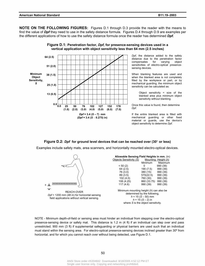
American National Standard B11.19–2003 NOTE ON THE FOLLOWING FIGURES: Figures D.1 through D.3 provide the reader with the means to find the value of Dpf they need to use in the safety distance formula. Figures D.4 through D.9 are examples per the different applications of how to use the safety distance formula once the reader has determined Dpf.
Dpf, the distance added to the safetydistance due to the penetration factorcompensates for varying objectsensitivities of electro-optical presence-sensing devices. When blanking features are used andwhen the blanked area is not completelyfilled by the workpiece or part, or bymechanical guarding, the minimum objectsensitivity can be calculated as:
Object sensitivity = size of theblanked area plus minimum objectsensitivity without blanking.
Once this value is found, then determine Dpf.
If the entire blanked area is filled withmechanical guarding or other fixedmaterial or guards, use the device’sobject sensitivity to determine Dpf.
Figure D.1: Penetration factor, Dpf, for presence-sensing devices used in a vertical application with object sensitivity less than 64 mm (2.5 inches)
178 (7.0)
152 (6.0)
127 (5.0)
102 (4.0)
76 (3.0)
50 (2.0)
25 (1.0)
0.0 0.0
13 (0.5)
25 (1.0)
38 (1.5)
51 (2.0)
64 (2.5)
Dpf = 3.4 (S – 7) mm (Dpf = 3.4 (S − 0.275) in)
Minimum Object
Sensitivity, S
Figure D.2: Dpf for ground level devices that can be reached over (30° or less)
Examples include safety mats, area scanners, and horizontally mounted electro-optical devices.
REACH-OVER Dpf = 1200 mm (48 in) for horizontal sensing
field applications without vertical sensing.
Allowable Sensing Field Heights in mm. (in) Objects Sensitivity (S) Mounting Height (h)
Minimum Maximum < 50 (2) 0 990 (39) 64 (2.5) 190 (7.5) 990 (39) 76 (3.0) 380 (15) 990 (39) 89 (3.5) 570(22.5) 990 (39) 102 (4.0) 760 (30) 990 (39) 108 (4.25) 860 (33.75) 990 (39)
117 (4.6) 990 (39) 990 (39)
Minimum mounting height (h) can also be determined by the following,
h = 15 (S – 50) mm h = 15 (S – 2) in
where S is the object sensitivity.
h NOTE - Minimum depth-of-field or sensing area must hinder an individual from stepping over the electro-optical
presence-sensing device or safety mat. This distance is 1.2 m (4 ft) if an individual can step over and pass unrestricted; 900 mm (3 ft) if supplemental safeguarding or physical barriers are used such that an individual must stand within the sensing area. For electro-optical presence-sensing devices inclined greater than 30º from horizontal, and for which you cannot reach over without being detected, use Figure D.1.
50
ANSI Store order #X204842 Downloaded: 8/18/2005 4:52:12 PM ETSingle user license only. Copying and networking prohibited.

American National Standard B11.19–2003
K (T total) + DpfDs =
Figure D.4: Example of guarding with object sensitivity less than 64 mm (2.5 inches)
NOTE - Where individuals can place themselves between the safeguarding device and the hazard zone and remain undetected, additional measures must be taken.
K (T total) Dpf
Ds
Hazard Area
Safety Distance (Ds) for devices with a larger value for object sensitivity must be placed farther from the hazard than a device with a smaller value for object sensitivity.
Figure D.5: Example of guarding with various object sensitivities
NOTE - Where individuals can place themselves between the safeguarding device and the hazard zone and remain undetected, additional measures must be taken.
REACH-THROUGH Dpf = 900 mm (3 ft) for reach through applications.
The top of the sensing field (“B”) is between 900 and 1200 mm (3 and 4 ft) above the floor. The bottom of the sensing field (“A”) is no more than 300 mm (1 ft) above the floor.
BA
REACH-OVER Dpf = 1200 mm (4 ft) for reach over applications.
A
If the individual cannot reach over the top of the sensing field and the bottom of the sensing field (“A”) is no more than 300 mm (1 ft) above the floor.
Figure D.3: Dpf for object sensitivities greater than 64 mm (2.5 inches) For electro-optical presence-sensing devices using large blanked areas, or if an individual can otherwise reach through or over the sensing field and not be detected, the distance between any two adjacent detection points shall not be greater than 600 mm (24 in), i.e., from one active point to the next active point above.
51
ANSI Store order #X204842 Downloaded: 8/18/2005 4:52:12 PM ETSingle user license only. Copying and networking prohibited.

American National Standard B11.19–2003
Figure D.6: Dpf for ground level devices that can be reached over (30° or less)
h
K (T total) Dpf
Minimum depth of field or sensing area must hinder an individual from stepping over the presence-sensing device or safety mat. This distance is 1.2 m (4 ft) if an individual can step over andpass unrestricted, 900 mm (3 ft) if supplemental safeguarding or physical barriers are used such that an individual must standwithin the sensing area.
Ds
Hazard Area
Allowable Sensing Field Heights in mm (in) Objects Sensitivity Mounting Height (h)
Minimum Maximum < 50 (2) 0 990 (39) 64 (2.5)) 190 (7.5) 990 (39) 76 (3.0) 380 (15) 990 (39) 89 (3.5) 570 (22.5) 990 (39) 102 (4.0) 760 (30) 990 (39) 108 (4.25) 860 (33.75) 990 (39)
117 (4.6) 990 (39) 990 (39)
Minimum mounting height (h) can also be determined by the following,
h = 15 (S – 50) mm h = 15 (S – 2) in
where S is the object sensitivity.
Area Scanner
Safety Light Curtain Safety Mat
Figure D.7: Single Control Device
Hazard Area
K (T total) Dpf
Ds
Safety Distance (Ds) for a Single Control Device includes a large Dpf of 2 meters (6.5 feet) due to the ability of the operator to stand between the device and reach towards the hazard.
52
ANSI Store order #X204842 Downloaded: 8/18/2005 4:52:12 PM ETSingle user license only. Copying and networking prohibited.

American National Standard B11.19–2003
Figure D.8: Two-hand Control & Two-Hand Trip Devices
Table D.1: Maximum Guard openings vs. Distance from Hazard Zone in millimeters (inches)
As a function of gap size As a function of distance Known Gap Minimum Distance Known Distance Maximum Gap
0 – 6 (0 – 0.24) 13 (0.5) < 13 (< 0.5) Not permitted 6.1 – 11 (0.25 – 0.375) 64 (2.5) 13 – 63.9 (0.5 – 2.49) 6 (0.250)
11.1 – 16 (0.376 – 0.625) 89 (3.5) 64 – 88.9 (2.5 – 3.49) 11 (0.375) 16.1 – 32 (0.626 – 1.250) 166 (6.5) 89 – 165.9 (3.5 – 6.49) 16 (0.625) 32.1 – 49 (1.251 – 1.875) 445 (17.5) 166 – 444.9 (6.5 – 17.49) 32 (1.250)
49.1 – 132 (1.876 – 5.000) 915 (36.0) 445 – 914.9 (17.5 – 35.99) 49 (1.875) > 132 (> 5.0) Not permitted ≥ 915 (≥ 36.0) 132 (5.000)
The point of detection must take into account fluctuations and variances in the field density and sensitivity due to environmental conditions and physical changes in the work area. This amount must be added to K(T total) to determine the total safety distance, Ds.
Variable detection area
Antenna(e)
K (T total) + variance
Ds
Hazard Area
Figure D.9: RF Presence-sensing Devices
Safety Distance (Ds) for Two-Hand Control and Two-Hand Trip applications have a Dpf = 0. When used as a safeguarding device, the position must be placed such that the safety distance is measured from the closest hand control to the hazard.
Ds = K (T total)Ds = K (T total)
Hazard Area
53
ANSI Store order #X204842 Downloaded: 8/18/2005 4:52:12 PM ETSingle user license only. Copying and networking prohibited.

American National Standard B11.19–2003
Figure D.10: Location of Guards vs. Openings; Distance from hazard in millimeters (inches)
At distances over 915 mm (36 in), use 132 mm (5 in) as a maximum opening.
54
AN
SI S
tore order #X204842 D
ownloaded: 8/18/2005 4:52:12 P
M E
TS
ingle user license only. Copying and netw
orking prohibited.

American National Standard B11.19–2003
Annex E: Applications and Attributes (Informative: the safeguarding and complementary equipment contained in the chart below, as well as their applications and attributes, are NOT intended as an all-inclusive list, but merely as additional information or guidance on some potential uses and capabilities of the listed safeguarding and complementary equipment)
Safeguarding Application(s)
(for safeguarding hazard areas where: ) Attribute(s)
Fixed barrier guard
• access, by individuals, to the hazard area is not required during normal operation of the machine;
• the barrier guard slot or opening, required for entry and removal of the material, workpiece or scrap, is of a size or location that will not allow a body part to reach the hazard area.
• protects individuals in the vicinity of the hazard area being safeguarded;
• is not dependent on any interaction with the individual(s) being safeguarded.
Interlocked barrier guard
• regular access to the hazard area is required for tool changes or adjustments, coil changes, scrap removal, et cetera;
• access to the hazard is not required during normal operation of the machine.
• protects individuals in the vicinity of the hazard area being safeguarded;
• is not dependent on any interaction with the individual(s) being safeguarded.
Adjustable barrier guard
• access, by individuals, to the hazard area is not required during normal operation of the machine;
• the guard slot or opening, required for entry and removal of the material, workpiece or scrap is of a size or location that will not allow a body part to reach the hazard area.
• protects individuals in the vicinity of the hazard area being safeguarded;
• is not dependent on any interaction with the individual(s) being safeguarded;
• requires adjustment to suit each job set-up; • is dependent on the training and supervision
of set-up personnel for effective safeguarding.
Movable barrier guard
access to the hazard area is necessary during normal operation of the machine.
• protects individuals in the vicinity of the hazard area being safeguarded;
• is dependent on the training and supervision of set-up personnel for effective safeguarding.
Use of a movable barrier device can significantly decrease machine productivity by increasing the time required to complete a production cycle.
Pullback (pull out) and restraint devices
access to the hazard area is necessary during normal operation of the machine.
• protects only the individual(s) using the device;
• provides no obstruction between the operator and the operation being performed;
• is dependent on the training and diligence of set-up and supervisory personnel.
55
ANSI Store order #X204842 Downloaded: 8/18/2005 4:52:12 PM ETSingle user license only. Copying and networking prohibited.

American National Standard B11.19–2003 Safeguarding Application(s) Attribute(s)
(for safeguarding hazard areas where: )
Presence-sensing device; electro-optical, R.F. and area scanning, safety mat and edge devices
the manufacturing process requires access to the hazard area, by individuals, during normal operation of the machine.
• protects individuals in the vicinity of the hazard area being safeguarded;
• provides no obstruction between the operator and the operation being performed;
• is not dependent on any interaction with the individual(s) being safeguarded.
Drop probe device
the manufacturing process requires access to the hazard area, by individuals, during normal operation of the machine.
• Protects only the individual(s) using the device;
• is dependent on the training and supervision of set-up personnel for effective safeguarding.
Two-hand control device
• the machine is provided with a part-revolution clutch, hydraulically or pneumatically actuated, or electrically or electronically driven (servo and variable speed drives);
• the manufacturing process requires access to the hazard area, by an individual(s), during normal operation of the machine.
• protects only the individual operating the device;
• provides no obstruction between the operator and the operation being performed.
Two-hand trip device
• the machine makes one complete machine cycle after the trip controls are momentarily actuated;
• the manufacturing process requires access to the hazard area, by an individual(s), during normal operation of the machine.
• protects only the individual operating the device;
• provides no obstruction between the operator and the operation being performed.
Single control device
• the machine is provided with a part-revolution clutch, hydraulically or pneumatically actuated, or electrically or electronically driven (servo and variable speed drives);
• the machine makes one complete machine cycle after the trip controls are momentarily actuated;
• the manufacturing process requires access to the hazard area, by an individual(s), during normal operation of the machine.
• protects only the individual operating the device;
• provides no obstruction between the operator and the operation being performed.
Awareness devices and signals
awareness devices or signals alert individuals of a pending or approaching hazard.
An awareness device or signal alerts individuals by means of audible sound or visible light.
Safe distance safeguarding
workpiece positioning and operator location eliminates the need for the operator to be in or near the hazard area during the hazardous portion of the machine cycle.
• protects only the operator who is required to maintain a position at a safe distance from the hazard area during hazardous motion of the machine;
• is not dependent on any interaction with the
56
ANSI Store order #X204842 Downloaded: 8/18/2005 4:52:12 PM ETSingle user license only. Copying and networking prohibited.

American National Standard B11.19–2003 Safeguarding Application(s) Attribute(s)
(for safeguarding hazard areas where: ) individual being safeguarded.
Safe holding safeguarding
the operator is required to hold the workpiece with both hands outside of the hazard area during the hazardous portion of the machine cycle.
• protects only the operator who is required to hold the workpiece with both hands outside of the hazard area during the hazardous portion of the machine cycle.
Safe opening safeguarding
an opening in a barrier guard with the workpiece in place prevents an individual(s) from reaching into the hazard area.
• protects individuals in the vicinity of the hazard area being safeguarded when the workpiece is in place;
• is not dependent on any interaction with the individual(s) being safeguarded.
Safe positioning safeguarding (hostage control)
operators or helpers assigned to the production process are not required to have access to the hazard area during normal production. The control must be located at a distance from the hazard area such that the operator or helper cannot reach the hazard before hazardous motion has ceased.
• protects only the individual(s) operating the control device provided;
• provides no obstruction between the operator and the operation being performed.
Safe work procedures
procedures developed by the user to ensure proper use and operation of the safeguarding or the machine for a particular task.
The user determines whether a safe work procedure is required to ensure that a safe work practice is achieved. Factors to consider in determining whether a safe work procedure is required may include, but are not limited to, the following: • where tasks are complex; • where tasks have high risk; • where training, skill or work experience is
limited; • where other safeguarding is removed or
bypassed; • where required to augment other
safeguarding.
Covers For safeguarding lubrication or inspection openings in guards or machine components, where such openings may provide access to a hazard.
• protects individuals in the vicinity of the hazard area being safeguarded;
• is not dependent on any interaction with the individual(s) being safeguarded.
Shields • necessary to contain chips or coolant, or
• a potential exists for the ejection of broken tooling or workpiece fragments.
• protects individuals in the vicinity of the hazard area being safeguarded;
• is not dependent on any interaction with the individual(s) being safeguarded.
57
ANSI Store order #X204842 Downloaded: 8/18/2005 4:52:12 PM ETSingle user license only. Copying and networking prohibited.