alumasc exterior building products ltd · 1.3 the ventilated cavity is created using timber battens...
TRANSCRIPT

Page 1 of 17
TECHNICAL APPROVALS FOR CONSTRUCTION
APPROVAL
INSPECTION
TESTING
CERTIFICATION
Alumasc Exterior Building Products LtdWhite House WorksBold RoadSutton, St HelensMerseyside, WA9 4JGTel: 01744 648400 Fax: 01744 648401e-mail: [email protected]: www.alumascfacades.co.uk
British Board of Agrément tel: 01923 665300Bucknalls Lane fax: 01923 665301Watford [email protected] WD25 9BA www.bbacerts.co.uk©2015
The BBA is a UKAS accredited certification body — Number 113. The schedule of the current scope of accreditation for product certification is available in pdf format via the UKAS link on the BBA website at www.bbacerts.co.uk
Readers are advised to check the validity and latest issue number of this Agrément Certificate by either referring to the BBA website or contacting the BBA direct.
ALUMASC VENTILATED SYSTEM (AVS)
ALUMASC VENTILATED RENDERED/ACRYLIC BRICK-SLIP SYSTEM FOR TIMBER FRAME BUILDINGSThis Agrément Certificate Product Sheet(1) relates to Alumasc Ventilated Rendered/Acrylic Brick-Slip System for Timber Frame Buildings, for use as an exterior wall cladding panel system.(1) Hereinafter referred to as ‘Certificate’.
CERTIFICATION INCLUDES:• factors relating to compliance with Building
Regulations where applicable• factors relating to additional non-regulatory
information where applicable• independently verified technical specification• assessment criteria and technical investigations• design considerations• installation guidance• regular surveillance of production• formal three-yearly review.
KEY FACTORS ASSESSEDStrength and stability — the system can accept surface loadings likely to be met in the UK (see section 6).
Performance in relation to fire — the system has a reaction to fire classification of A2-s1, d0 in accordance with BS EN 13501-1 : 2007 (see section 7).
Weathertightness — the system is weather and moisture resistant (see section 9).
Durability — the system has acceptable durability and can be expected to have a service life in excess of 30 years (see section 13).
Agrément Certificate15/5211
Product Sheet 1
The BBA has awarded this Certificate to the company named above for the system described herein. This system has been assessed by the BBA as being fit for its intended use provided it is installed, used and maintained as set out in this Certificate.
On behalf of the British Board of Agrément
Date of First issue: 6 May 2015 Simon Wroe Claire Curtis-Thomas Head of Approvals — Engineering Chief ExecutiveCertificate amended on 25 August 2015 to include update to Figure 1.

Page 2 of 17
In the opinion of the BBA, Alumasc Ventilated Rendered/Acrylic Brick-Slip System for Timber Frame Buildings, if installed, used and maintained in accordance with this Certificate, can satisfy or contribute to satisfying the relevant requirements of the following Building Regulations (the presence of a UK map indicates that the subject is related to the Building Regulations in the region or regions of the UK depicted):
The Building Regulations 2010 (England and Wales) (as amended)
Requirement: A1 Loading
Comment: The system is acceptable. See sections 4.2 and 6.3 of this Certificate.Requirement: B4(1) External fire spread
Comment: The system meets Class 0 requirement. See sections 7.1 to 7.3 and 7.6 of this Certificate.Requirement: C2(b)(c) Resistance to moisture
Comment: The system satisfies this Requirement. See sections 9 and 11.2 to 11.5 of this Certificate.Regulation: 7 Materials and workmanship
Comment: The system is acceptable. See section 13 and the Installation part of this Certificate.
The Building (Scotland) Regulations 2004 (as amended)
Regulation: 8(1)(2) Durability, workmanship and fitness of materials
Comment: The system can contribute to a construction satisfying this Regulation. See sections 12 and 13 and the Installation part of this Certificate.
Regulation: 9 Building standards applicable to constructionStandard: 1.1(a)(b) Structure
Comment: The system is acceptable, with reference to clause 1.1.1(1)(2). See sections 4.2 and 6.3 of this Certificate.Standard: 2.6 Spread to neighbouring buildings
Comment: The system can contribute to satisfying this Standard, with reference to clause 2.6.4(1)(2). See sections 7.1 to 7.3 of this Certificate.
Standard: 2.7 Spread on external walls
Comment: The system can contribute to satisfying this Standard, with reference to clause 2.7.1(1)(2). See sections 7.4 to 7.6 of this Certificate.
Standard: 3.10 Precipitation
Comment: The system will contribute to satisfying this Standard, with reference to clauses 3.10.1(1)(2) to 3.10.3(1)(2), and 3.10.5(1)(2) to 3.10.6(1)(2) See section 9 of this Certificate.
Standard: 3.15 Condensation
Comment: The system can satisfy or contribute to satisfying this Standard, with reference to clauses 3.15.1(1), 3.15.2(1), 3.15.4(1) and 3.15.5(1). See sections 9 and 11.2 to 11.5 of this Certificate.
Standard: 7.1(a)(b) Statement of sustainability
Comment: The product can contribute to satisfying the relevant requirements of Regulation 9, Standards 1 to 6, and therefore will contribute to a construction meeting a bronze level of sustainability as defined in this Standard.
Regulation: 12 Building standards applicable to conversions
Comment: All comments given for this system under Regulation 9, Standards 1 to 6, also apply to this Regulation, with reference to clause 0.12.1(1)(2) and Schedule 6(1)(2).
(1) Technical Handbook (Domestic). (2) Technical Handbook (Non-Domestic).
The Building Regulations (Northern Ireland) 2012
Regulation: 23 (a)(i)(iii)(b) Fitness of materials and workmanship
Comment: This system is acceptable. See section 13 and the Installation part of this Certificate.Regulation: 28 Resistance to moisture and weather
Comment: The system will contribute to satisfying this Regulation. See sections 9.1 and 9.2 of this Certificate.Regulation: 29 Condensation
Comment: The system is acceptable. See sections 9 and 11.2 to 11.5 of this Certificate.Regulation: 30 Stability
Comment: The system is acceptable as set out in section 4.2 and 6.3 of this Certificate.Regulation: 36 External fire spread
Comment: The system meets the Class 0 requirements. See sections 7.1 to 7.3 and 7.6 of this Certificate.
Construction (Design and Management) Regulations 2015Construction (Design and Management) Regulations (Northern Ireland) 2007
Information in this Certificate may assist the client, Principal Designer/CDM co-ordinator, designer and contractors to address their obligations under these Regulations.See section: 3 Delivery and site handling (3.1 and 3.4).
Regulations

Page 3 of 17
Additional Information
NHBC Standards 2014NHBC accepts the use of Alumasc Ventilated Rendered/Acrylic Brick-Slip System for Timber Frame Buildings, provided it is installed, used and maintained in accordance with this Certificate, in relation to NHBC Standards, Chapter 6.2 External timber framed walls, Chapter 6.3 Internal walls, Chapter 6.9 Curtain walling and cladding and Chapter 8.2 Wall and ceiling finishes.
Technical Specification
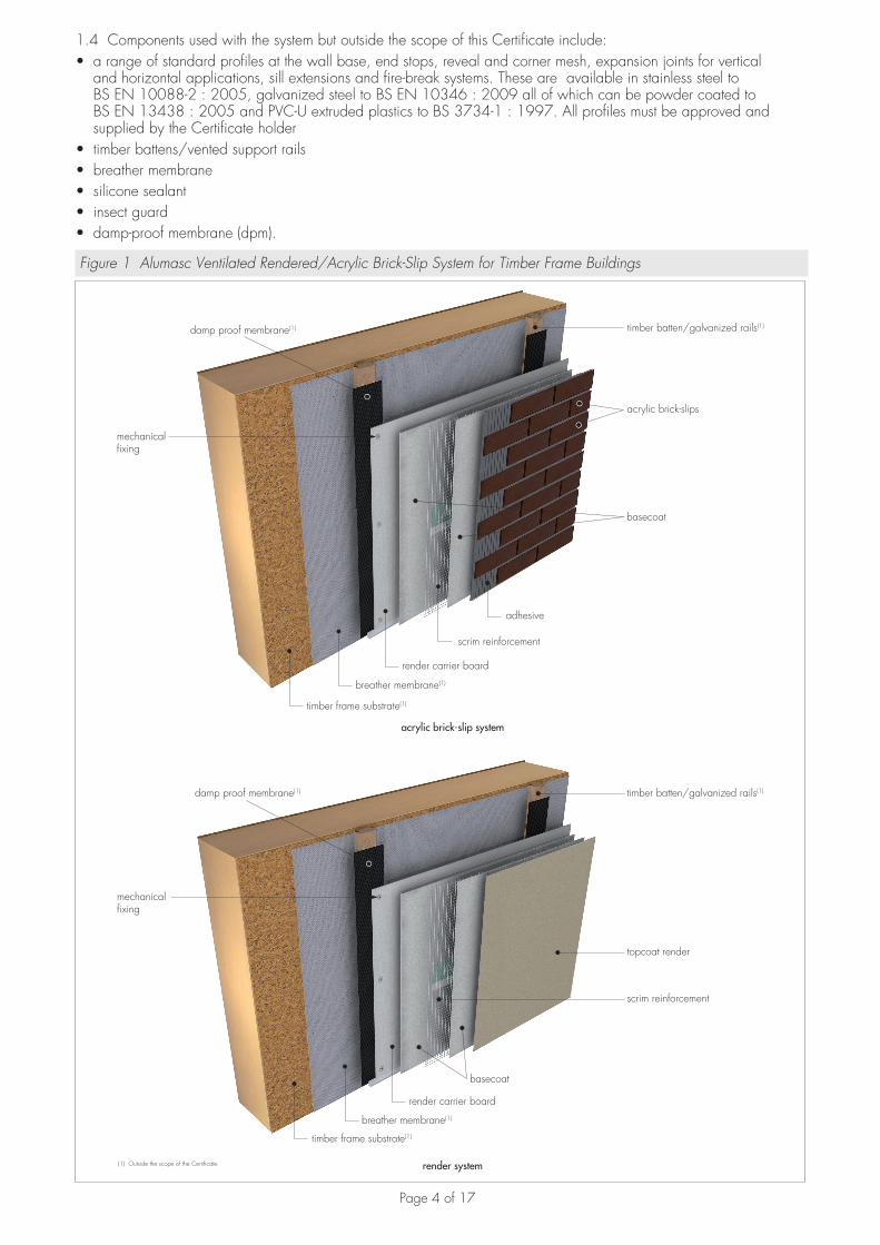
1 Description1.1 The Alumasc Ventilated Rendered/Acrylic Brick-Slip System for Timber Frame Buildings consists of Alumasc Render Carrier Board, a magnesium oxide core externally bonded with Alumasc Base Coat (ABC) and finished with ST Silkolit silicone render or Alumasc Acrylic Bricks or bonded with M.R. Scrim Adhesive and finished with M.R. S7 Dash Receiver for installation to suitably sheathed timber-frame buildings incorporating an appropriately drained and vented cavity (see Figure 1).
1.2 The system comprises:Render carrier board• Alumasc Render Carrier Board — a water and mould resistant magnesium oxide board. The boards are available
with nominal characteristics of:Width (mm) 1200Length (mm) 2400Thickness (mm) 12Density (kg·m–3) 1050Modulus of rapture (N·mm2) 17.7 — transverse direction (dry conditions) 12.4 — longitudinal direction (dry conditions).Mechanical fixings• Ejot JT3 ST-2-6.0 — 6.0 mm diameter self-drilling screws for metal and timber battens• Ejot SH3 STS-5.0 x 42 — 5.0 mm diameter self-tapping screws for timber battens.
Basecoat• Alumasc Base Coat (ABC) — a cement-based, high polymer-modified basecoat, supplied in powder form. To be
used with ST Silkolitt and Acrylic Bick-Slips finishes• M.R. Scrim Adhesive — a mixture of Portland cement, quartz sand and other additives, supplied in powder form. To
be used with M.R. S7 Dashing Render.
Reinforcement• Alumasc Scrim Reinforcement — a 1 m-wide alkali-resistant glassfibre mesh, with a mesh size of 6 mm by 6 mm
weighing approximately 150 g·m–2. Primer• ST Primer — a silicone primer containing fine quartz grains for use as a bonding aid and pre-coat.
Brick-slips adhesive• Alumasc Acrylic Brick-Slips Adhesive — an organic-bound, water-based cement-free pre-mixed adhesive.
Finishes• Alumasc Acrylic Brick-Slips — poly-acrylic slips containing quartz sands fillers, typically supplied in standard size of
dimensions 65 mm by 215 mm by 4 mm with a nominal weight of 6 kg·m–2. Available as straight brick-slips and corner brick-slips and in various colours. Other sizes are available on request from the Certificate holder
• ST Silkolitt — a silicone finish, bonded, textured render supplied as a paste in three grades of grain size, 1.5 mm, 2.5 mm and 3.5 mm
• Spar-dash finish: — M.R. S7 Dashing Render — a polymer-modified fibre-reinforced cement-based mortar supplied as a powder to
which water is added. Available coloured white, salmon, terracotta red, red, burgundy, gold, yellow, peach, grey, brown, light cream, cream or pink. Other colours are available to order
— M.R. Spar-Dash Aggregate — available in a range of colours to suit the M.R. S7 Dashing Render.
1.3 The ventilated cavity is created using timber battens or vented galvanized top hat support rails.
Page 4 of 17
1.4 Components used with the system but outside the scope of this Certificate include:• a range of standard profiles at the wall base, end stops, reveal and corner mesh, expansion joints for vertical
and horizontal applications, sill extensions and fire-break systems. These are available in stainless steel to BS EN 10088-2 : 2005, galvanized steel to BS EN 10346 : 2009 all of which can be powder coated to BS EN 13438 : 2005 and PVC-U extruded plastics to BS 3734-1 : 1997. All profiles must be approved and supplied by the Certificate holder
• timber battens/vented support rails• breather membrane• silicone sealant• insect guard• damp-proof membrane (dpm).
Figure 1 Alumasc Ventilated Rendered/Acrylic Brick-Slip System for Timber Frame Buildings
mechanical fixing
adhesive
scrim reinforcement
render carrier board
breather membrane(1)
timber frame substrate(1)
acrylic brick-slips
basecoat
topcoat render
timber frame substrate(1)
breather membrane(1)
render carrier board
basecoat
scrim reinforcement
mechanical fixing
acrylic brick-slip system
render system
timber batten/galvanized rails(1)
timber batten/galvanized rails(1)
(1) Outside the scope of the Certificate.
damp proof membrane(1)
damp proof membrane(1)

Page 5 of 17
2 Manufacture2.1 The board is manufactured using inorganic substances and four layers of alkaline resistant glassfibre mesh, naturally cured using no energy.
2.2 As part of the assessment and ongoing surveillance of product quality, the BBA has:• agreed with the manufacturer the quality control procedures and product testing to be undertaken• assessed and agreed the quality control operated over batches of incoming materials• monitored the production process and verified that it is in accordance with the documented process• evaluated the process for management of nonconformities• checked that equipment has been properly tested and calibrated• undertaken to carry out the above measures on a regular basis through a surveillance process, to verify that the
specifications and quality control operated by the manufacturer are being maintained.
2.3 The management system of Alumasc Exterior Building Products Ltd has been assessed and registered as meeting the requirements of BS EN ISO 9001 : 2008 by Centre for Assessment Ltd (Certificate 02/1832).
3 Delivery and site handling3.1 Boards are stacked on timber bearers, raised from the ground on a pallet. Each pallet pack incorporates the Certificate holder’s name, product name, edge type, thickness, width, length, number of boards per pallet and pallet weight.
3.2 Boards must be stored flat in dry conditions indoors and be under cover on a level surface protected on site from contamination and weather at all times. Boards should not be leant upright for long periods of time.
3.3 Boards should always be lifted by two people and not dragged across each other to prevent unnecessary scratching or damage. The Certificate holder’s instructions on site handling and storage must be followed.
3.4 The basecoat and render components must be stored in dry conditions, off the ground, and protected from frost at all times. Bags of unopened render have a shelf-life of 12 months when stored correctly.
3.5 The Acrylic Brick-Slip Adhesive must be protected from exposure to sunlight, frost and stored below temperatures of 30°C. Tubs of unopened adhesive have a shelf-life of 18 months when stored correctly.
3.6 Components are delivered to site in the quantities and packaging listed in Table 1. Each package bears the Certificate holder’s name, product name and batch number.
Table 1 Component packaging details
Component Quantity and package
12 mm Alumasc Render Carrier Board 58 boards per pallet , 2.1 tonnes per pallet
Alumasc Base Coat (ABC) 25 kg bag
M.R. Scrim Adhesive 25 kg bag
Alumasc Acrylic Brick-Slip Adhesive 20 kg tub
Alumasc Acrylic Brick-Slips: Straight Corner
10 kg box3.5 kg box
ST Primer 23 kg plastic tub
ST Silkolitt 25 kg plastic tub
M.R. S7 Dashing Render 25 kg bag
M.R. Spar-Dash Aggregate 25 kg bag
Mechanical fixings boxed by manufacturer
Alumasc Scrim Reinforcement 1 m wide, 50 m rolls
Assessment and Technical InvestigationsThe following is a summary of the assessment and technical investigations carried out on Alumasc Ventilated Rendered/Acrylic Brick-Slip System for Timber Frame Buildings.
Design Considerations
4 General4.1 The Alumasc Ventilated Rendered/Acrylic Brick-Slip System for Timber Frame Buildings is satisfactory for use as an external wall cladding in timber-frame buildings.
4.2 The timber frame substrate wall to which the system is fixed must be structurally sound and constructed in accordance with the requirements of the relevant national Building Regulations and Standards (see sections 4.3).

Page 6 of 17
4.3 Timber stud walls and timber battens must be structurally sound, designed and constructed in accordance with BS EN 1995-1-1 : 2004 (Eurocode 5). Timber must be preservative treated in accordance with BS EN 351-1 : 2007.
4.4 The design must include:• Alumasc Render Carrier Board as backing of the render system• a ventilated and drained cavity system incorporating an insect guard to all ventilation openings• effective detailing around window openings to ensure that wind-driven rain cannot penetrate to the hidden members
in the surround and from the cavity• an effective breather membrane on the inside, to ensure the timber frame structure is protected.
4.5 The system must only be applied above the damp-proof course (dpc) level and at a minimum of 150 mm above ground level.
5 Practicability of installationThe system is designed to be installed by a competent builder, or a contractor, experienced with this type of system.
6 Strength and stability6.1 The boards have adequate strength and can be used with the render system.
6.2 A suitably qualified and experienced individual must check the design and installation of the cladding system.
6.3 Design wind loadings should be calculated in accordance with BS EN 1991-1-4 : 2005 (Eurocode 1). Due consideration should be given to the higher-pressure coefficients applicable to corners of the building as recommended in this Standard.
6.4 The contribution of the board, insulation and render finish on the stability of the substrate is assumed to be negligible. The substrate wall, must be able to take the full wind actions and racking loads and be capable of sustaining the weight of the system. The adequacy of the substrate is outside the scope of this Certificate and must be verified by a suitably qualified and experienced individual.
6.5 For each wall panel, a partial safety factor of 1.3 and the values of modification factor kmod in Table 2 (of this Certificate) as defined in BS EN 1995-1-1 : 2004 (Eurocode 5), sections 2.4.1 and 3.1.3 respectively, are to be used to determined the values of design values of racking loads.
Table 2 Values of modification factors kmod
Load duration class Service class
Class 1 Class 2 Class 3
Short-term actions 0.9 0.7 0.5
Instant actions 1.1 0.9 0.7
6.6 The characteristic pull-through resistance of Alumasc Render Carrier Board was calculated (by test) using a minimum safety factor of 3 in accordance with BS EN 1383 : 1999 for 4.8 mm by 42 mm self-drilling stainless steel screws (BMDW4842) and is given in Table 3 of this Certificate.
Table 3 Characteristic pull-through resistance
Board thickness (mm) 12
Plate diameter of anchor mm) 4.8
Characteristic pull-through resistance(1) (per anchor) (N) 1191
Factor of safety(2) 3.0
Design pull-through anchor resistance (N) 397
(1) Characteristic value in accordance with BS EN 1990 : 2002, Annex D7.2.(2) The safety factor of 3.0 is applied and based on the assumption that all render carrier boards are subject to
adequate quality control.
6.7 Tests and calculations carried out confirm that the design wind load resistance of the system is 5 kN·m2. This design wind load resistance result is valid provided the designer ensures the following:• the characteristics of the mean Alumasc Render Carrier Board are: — A1 non-combustible reaction to fire classification in accordance with BS EN 13501-1 : 2007 — 12 mm thickness — minimum density of 1050 kg·m–3
— nominal tensile strength (perpendicular to plane) of 2.00 Nmm2 in accordance with BS EN 319 : 1993.
• that the fixing of the support rail/timber batten to the substrate wall has adequate pull-out resistance for the calculated loads (outside the scope of this Certificate) and the examples are covered in Table 4
• that the design of the timber frame and the support rail/timber batten must be such as to limit the mid-span deflections to L/200 and cantilever deflections to L/180
Page 7 of 17
• that the vertical support rails/timber battens are no more than 600 mm centres apart and that fixings are at no more than 220 mm centres apart.
6.8 Typical characteristic pull-out strengths for the fixings listed in section 1.2 are given in Table 4; however, these values are dependent on the substrate. Fixings must be selected to suit the loads and substrate concerned.
Table 4 Fixings — typical characteristic pull-out strengths
Fixing type Substrate Diameter (mm)
Effective anchorage depth (mm)
Typical pull-out strength (kN)
Ejot JT3 ST-2-6.02 mm Aluminium
(g = 215 N·mm–2)Timber
6 —40
3.283.96
Ejot SH3 STS-5.0 x 42 Timber 5 2540
3.104.30
Impact resistance6.9 Tests for resistance to hard and soft body impact, indicated that the system had adequate resistance to impact and therefore may be considered suitable for use in all Use Categories(1).(1) As defined in ETAG 004 : 2013, see Table 5.
Table 5 Definition of Use Categories
Use Category Description
I A zone readily accessible at ground level to the public and vulnerable to hard body impacts but not subjected to abnormally rough use.
II A zone liable to impacts from thrown or kicked objects, but in public locations where the height of the ETICS will limit the size of the impact; or at lower levels where access to the building is primarily to those with some incentive to exercise care.
III A zone not likely to be damaged by normal impacts caused by people or by thrown or kicked objects.
7 Performance in relation to fire7.1 The reaction to fire classification for the external surface of the system in accordance with BS EN 13501-1 : 2007 or as defined in the national Building Regulations is shown in Table 6.
Table 6 System fire classifications
Rendering/ brick-slip system Classification
M.R. S7 Dashing Render + Dash Aggregate
A2-s1, d0ST Silkolitt
Alumasc Acrylic Brick-Slips
7.2 For houses in Scotland and for all buildings in England, Wales and Northern Ireland, the system is suitable for use on or at any distance from, the boundary.
7.3 The system is restricted for use in buildings up to 18 metres in height.
7.4 For flats, maisonettes and non-domestic buildings in Scotland, the system is suitable only for use more than one metre from the boundary.
7.5 The calculations for unprotected areas may apply with the use of the system, dependent on the fire resistance characteristics of the wall.
7.6 To limit the risk of fire spread between floors in buildings subject to national Building Regulations, fire barriers must be incorporated in the cavity as required under these Regulations, but should not block essential ventilation pathways. Guidance on fire barriers can be found in BRE Report BR 135 : 2003.
8 Proximity of flues and appliancesWhen the insulation system is installed in close proximity to certain flue pipes, the relevant provisions of the national Building Regulations should be met:England and Wales — Approved Document JScotland — Mandatory Standard 3.19, clauses 3.19.1(1)(2) to 3.19.4(1)(2) and 3.19.8(1)(2)
(1) Technical Handbook (Domestic).(2) Technical Handbook (Non-Domestic).
Northern Ireland — Technical Booklet L.

Page 8 of 17
9 Weathertightness9.1 The system resists the passage of moisture and from weather. Any water collecting in the cavity due to rain or condensation will be removed by drainage and ventilation.
9.2 The air space between the back of the boards and the supporting substrate should be at least 25 mm wide(1).(1) Guidance on recommended cavity widths is given in NHBC Standards, Chapter 6.2 External timber framed walls and Chapter 6.9 Curtain
walling and cladding.
10 Water absorptionThe water absorption of Alumasc Render Carrier Board is 8.6% when tested in accordance with BS EN 322 : 1993.
11 Thermal conductivity and risk of condensation11.1 The board has a thermal conductivity value of 0.307 W·m–1·K–1.
11.2 The relevant components of the system have a water vapour resistance such that, under the conditions likely to be found in dwellings in the United Kingdom, interstitial condensation should not occur within the wall.
11.3 If a system is to be used on the external walls of rooms expected to have continuous high humidity, care must be taken in the design of the rooms to avoid possible problems from the formation of interstitial condensation in the wall.
11.4 When using Alumasc Render Carrier Board, consideration must be given to the overall design to minimise the risk of condensation, and the recommendations contained in BS 5250 : 2011.
11.5 Ventilation openings in the system should be at least 5 000 mm2·m–1 run of cladding.
12 Maintenance and repair12.1 Periodic inspections are recommended to assess the need for cleaning, maintenance painting, localised repairs and element replacements, such as joints seals and fixings to ensure that ingress of water does not occur. Necessary repairs must be carried out immediately (see sections 12.2 and 12.3).
12.2 Damaged areas must be repaired using appropriate materials and advice should be sought from the Certificate holder.
12.3 Damaged boards must be repaired or replaced as soon as is practicable, following the Certificate holder’s instructions and observing all necessary health and safety regulations.
13 Durability13.1 The durability and service life of the system will depend on the building location, immediate environment and intended use of the building.
13.2 Provided regular maintenance is carried out, as described in section 12.1 and in accordance with the Certificate holder’s instructions, the system can be expected to have a service life in excess of 30 years when used in the normal climatic conditions found in the UK.
Installation
14 Site survey and preliminary work14.1 A pre-installation survey of the property must be carried out to determine suitability for treatment and any repairs necessary to the building structure before application of a system. A specification is prepared for each elevation of the building indicating:• the position of beads• detailing around windows, doors and at eaves• damp-proof course (dpc) level• exact position of expansion joints, if required• areas where flexible sealants must be used• any alterations to external plumbing, where required.
14.2 The survey should include tests conducted on the walls of the building by the Certificate holder or their approved installers (see section 15) to determine the pull-out tests for mechanical fixings for the appropriate substrate. An assessment and recommendation should be made to withstand the building’s expected wind loading, based on calculations using the fixing’s pull-out resistance test data. In addition, the type and number of fixings are selected as per sections 6 and 16.13). The advice of the Certificate holder should be sought to ensure the proposed fixing pattern is sufficient.
14.3 On existing buildings, purpose-made window sills must be fitted to extend beyond the finished face of the system. New buildings should incorporate suitably deep sills.
Page 9 of 17
14.4 All modifications and necessary repairs to the building structure are completed before installation commences.
15 Approved installersApplication of the system, within the context of this Certificate, must be carried out by approved installers recommended or recognised by the Certificate holder. Such an installer is a company:• employing operatives who have been trained and approved by the Certificate holder to install the system• which has undertaken to comply with the Certificate holder’s application procedure, containing the requirement for
each application team to include at least one member operative trained by the Certificate holder• subject to at least one inspection per annum by the Certificate holder to ensure suitable site practices are being
employed. This may include unannounced site inspections.
16 ProcedureGeneral16.1 Installation of the system should be carried out strictly in accordance with the provisions of this Certificate and the Certificate holder’s installation instructions.
16.2 The render carrier board support system to which the render system is applied must be capable of transmitting its self-weight and the wind load to the structure. The adequacy of the structural frame must be verified by a suitably qualified engineer.
16.3 Movement joints must be incorporated into the system at the required locations identified by the building designer (see sections 16.15 and 16.16). Existing movement joints should be continued through the system.
16.4 The breather membrane must be installed and properly overlapped in accordance with the instructions of the membrane manufacturer and the building designer.
16.5 For a drainage cavity, the steel rail or timber batten used is fixed directly into the structural frame and the board fixed to the battens/rails. The frame studs or cavity drainage battens/ rails should be at a maximum of 600 mm centres.
16.6 A ventilated cavity must be of a suitable specification (ie minimum of 25 mm width) created by timber battens or vented render-board support rails.
16.7 Alumasc Render Carrier Board should be dry during installation at temperatures of 5ºC or above.
16.8 Application of the render or brick-slip system must not be carried out at temperatures below 5°C or above 30°C, nor if exposition to frost is likely, and the coating must be protected from rapid drying. Weather conditions, therefore, should be monitored to ensure correct curing conditions.
16.9 The finished render system should be no thicker than 12 mm.
16.10 All window and door openings must be sealed strictly in accordance with the Certificate holder’s installation instructions to ensure that they are weathertight (see Figures 6 and 7).
Positioning and securing render carrier boards16.11 The Alumasc vented base profile is secured to the external substrate above the dpc using the approved profile fixings at approximately 300 mm centres (see Figure 2).

Page 10 of 17
Figure 2 Typical section of base detail
acrylic brick-slip/render system
render carrier board
cavity
sheathing board withbreather membrane
timber frame substrate
intumescent strips − fire barriers
PVC clip-on drip profile
vent profile
typical section of base detail
16.12 The first run of render carrier boards is positioned on the vented base profile, securely fixed to the rails/ battens using the project-specific fixing type (see section 1.2). The boards are fitted with the textured face out to improve the adhesion of the render to the board. Subsequent rows of boards are positioned so that vertical joints are staggered and overlap at the building corners (see Figure 3). Gaps of 3 mm to 4 mm are created between the boards using a suitable spacer. Alignment should be checked as work proceeds.
16.13 Mechanical fixings are applied through each render carrier board to secure them during installation of the system. Mechanical fixings screws should be 20 mm in from the edge of the board and 40 mm from the end and a maximum of 220 mm screw spacing. The screws should not be over-tightened.

Page 11 of 17
Figure 3 Typical board fixing pattern
2400 mm x 1200 mm render carrier board
30 fixings per board
220 mm
6 fix
ings
600 ctrs
20 mm
40 mm
windows and openings
220 mm
200 (min)
15 mm
15 mm
Movement joints16.14 Expansion joints in the substrate must be continued through the system. The joint detail using purpose-made metal or PVC trims is illustrated in Figure 4.
16.15 Horizontal movement joints in accordance with BS EN 13914-1 : 2005 must be provided at every floor to accommodate vertical shrinkage in the timber frame and to follow movement joints in the substructure.
16.16 Vertical movement joints in accordance with BS EN 13914-1 : 2005 should be provided at a maximum of 15 m intervals. The actual spacing and position of the joints will be determined by the shape of the area to be rendered and should coincide with movement joints in the structure and allow for the same degree of movement.

Page 12 of 17
Figure 4 Expansion joint detail
vertical movement bead
sheathing with breaather membrane
timber frame substrate
battenrender carrier board
brick-slip/render system
Rendering and Finishing16.17 This Alumasc Base Coat is prepared by mixing the contents of each 25 kg bag with 4.5 to 5.0 litres of clean water.
16.18 The basecoat is applied either by spray equipment or stainless steel trowel to the surface of the dry render carrier board to a minimum thickness of 5 mm. The mesh is bedded immediately into the basecoat with 75 mm minimum overlap at joints and must be in the upper third of the basecoat render. An additional ‘slurry coat’ (1 mm to 2 mm) may be required to achieve the necessary smooth finish. Additional pieces of reinforcing mesh (250 mm by 500 mm) are used diagonally at the corners of openings, as shown in Figure 5. Corner details are reinforced using the corner beads.
Figure 5 Reinforcement at openings
glassfibre mesh
45°
250
500
Silicone Finish16.19 The drying period of any render will depend on the applied thickness and weather conditions; however, the basecoat must be left to harden for 3 to 5 days and any contaminants such as grease and chalking removed before the ST Primer is applied by roller or brush. The ST Primer is allowed to dry before application of the ST Silkolitt.
16.20 ST Silkolitt is supplied ready to use although a maximum of 2% clean water (250 ml maximum) can be mixed into the 25 kg tub prior to application. ST Silkolitt is applied by stainless steel trowel or spray equipment to the grain sizes of 1.5 mm, 2.5 mm or 3.5 mm. It can also be applied by spray equipment. The finish is textured in a circular motion with a plastic trowel until the desired effect is achieved.

Page 13 of 17
16.21 To prevent the render from drying too rapidly, it should not be applied in direct sunlight and continuous surfaces should be completed without a break.
Dashing Render Finish16.22 M.R. Scrim Adhesive is prepared by mixing each 25 kg bag with 4.5 to 5 litres of clean water and a bed coat is trowel-applied to the surface of render carrier boards to a minimum thickness of 3 mm. Additional pieces of reinforcing mesh (250 mm by 500 mm) are used diagonally at the corners of openings, as shown in Figure 5. Corner details are reinforced using the corner beads.
16.23 The scrim adhesive must be allowed to harden and dry for between one and three days depending on the environment before application of the M.R. S7 Dashing Render.
16.24 M.R. S7 Dashing Render is prepared by mixing the contents of each 25 kg bag with approximately 5.0 to 5.6 litres of water. Care must be taken to ensure an even dispersion of the resin and fibre reinforcement.
16.25 One coat of M.R. S7 Dashing Render trowel-applied to a minimum thickness of 8 mm. For the M.R. S7 Dashing Render, a minimum of three bags of suitable spar-aggregate should be emptied into a clean wheelbarrow or tub and any excess water allowed to drain before being mixed thoroughly. While the M.R. S7 Dashing Render is still soft, the aggregate is thrown or sprayed onto the surface.
16.26 On completion, the surface must be checked to ensure that an even coverage of spar dash has been achieved. Where necessary, the aggregate should be lightly tamped to ensure a good bond.
Acrylic Bricks-Slips16.27 The Alumasc Base Coat must be left to harden for three to five days and any contaminants such as grease and chalking removed before the ST Primer is applied by roller or brush colour matching.
16.28 ST Primer is applied by roller or brush to the entire surface of basecoat and left to dry, the colour to match the acrylic brick-slip adhesive.
16.29 Alumasc Acrylic Brick-Slip Adhesive is applied by a 5 mm notch trowel to the area of basecoat to receive the brick-slips.
16.30 Acrylic brick-slips are applied by hand in brick bond fashion, in line and level into adhesive. The brick-slips should be fully encapsulated in adhesive. Work is carried out from top to bottom lines.
16.31 Joints are normally 10 mm (minimum) wide. When pointing, a suitably-sized brush is used to smooth the acrylic adhesive into the joints and fully encapsulate the brick-slips. The adhesive is left to dry.
All finishes16.32 After application, care must be taken to protect the render/brick-slips from direct sunlight, drying winds, rain, mist and cold (less than 5°C on a falling thermometer) to prevent the drying time from being too rapid or excessively prolonged.
16.33 The decorative finish should not be applied in wet weather, at temperatures below 5°C or when frost is expected. Freshly coated work should be protected from rain (minimum of one week for brick-slips).
16.34 Care must be taken in the detailing of the system around openings and projections (see Figures 6 and 7).

Page 14 of 17
Figure 6 Window head and sill details
timber frame substrate
sheathing board with breather membrane
cavity
render carrier board
PVC clip-on drip profile
vent profile
window
timber frame substrate
sheathing board with breather membrane
cavity
render carrier board
edge protection profile
vent profile
windowwindow sill
render system
acrylic brick-slip/render system
Figure 7 Window jamb details
render carrier board
edge protection profile withstop bead bedded on mastic
corner bead
timber frame substrate
sheathing board with breather membrane
brick slip/render system

Page 15 of 17
Figure 8 External corner detail
timber frame substrate
breather membrane
render carrier board
brick slip/render system
timber batten
corner bead
16.35 At the tops of walls, the system must be protected by an adequate overhang or by an adequately sealed purpose-made coping.
Figure 9 Parapet detail
timber frame substrate
render carrier board
brick slip/render system
sheathing board with breather membrane
dpc skyline coping system
vent profile
edge protection profile

Page 16 of 17
Technical Investigations
17 Tests17.1 Tests were carried out and the results assessed to determine:• resistance to hard and soft body impacts• thermal conductivity• water vapour permeability• resistance to heat/sun cycling.
17.2 An assessment was made of test data relating to:• density• bending strength• modulus of elasticity in bending• shear strength• racking resistance• resistance to organic growth• dimensional stability• water absorption• water vapour permeability• soft and hard body impact• resistance to fire• reaction to fire• thermal conductivity.
17.3 The system’s resistance to wind loading, mechanical resistance and stability was assessed.
18 InvestigationsThe manufacturing process was evaluated, including the methods adopted for quality control, and details were obtained of the quality and composition of the materials used.
BibliographyBS 3734-1 : 1997 Rubber — Tolerances for Products — Dimensional TolerancesBS 5250 : 2011 Code of practice for control of condensation in buildingsBS EN 319 : 1993 Particleboards and Fibreboards — Determination of Tensile Strength Perpendicular to the Plane of the BoardBS EN 322 : 1993 Wood-based panels — Determination of moisture contentBS EN 351-1 : 2007 Durability of wood and wood-based products — Preservative-treated solid wood — Classification of preservative penetration and retentionBS EN 1383 : 1999 Timber structures — Test methods — Pull-through resistance of timber fastenersBS EN 1990 : 2002 Eurocode — Basis of structural designBS EN 1991-1-4 : 2005 Eurocode 1 : Actions on structures — General actions — Wind actionsBS EN 1995-1-1 : 2004 Eurocode 5 : Design of timber structures — General — Common rules and rules for buildingsBS EN 10088-2 : 2005 Stainless steels — Technical delivery conditions for sheet/plate and strip of corrosion resisting steels for general purposesBS EN 10346 : 2009 Continuously hot-dip coated steel flat products — Technical delivery conditionsBS EN 13438 : 2005 Paints and varnishes — Powder organic coatings for galvanized or sherardised steel products for construction purposesBS EN 13501-1 : 2007 Fire classification of construction products and building elements. Classification using test data from reaction to fire testsBS EN 13914-1 : 2005 Design, preparation and application of external rendering and internal plastering — External renderingBS EN ISO 9001 : 2008 Quality management systems — RequirementsBRE Report (BR 135 : 2003) Fire Performance of External Insulation For Walls of Multi-Storey BuildingsETAG 004 : 2013 Guideline for European Technical Approval of External Thermal Insulation Composite Systems (ETICS) with Rendering

Page 17 of 17
Conditions of Certification
19 Conditions19.1 This Certificate:• relates only to the product/system that is named and described on the front page• is issued only to the company, firm, organisation or person named on the front page — no other company, firm,
organisation or person may hold or claim that this Certificate has been issued to them• is valid only within the UK• has to be read, considered and used as a whole document — it may be misleading and will be incomplete to be
selective• is copyright of the BBA• is subject to English Law.
19.2 Publications, documents, specifications, legislation, regulations, standards and the like referenced in this Certificate are those that were current and/or deemed relevant by the BBA at the date of issue or reissue of this Certificate.
19.3 This Certificate will remain valid for an unlimited period provided that the product/system and its manufacture and/or fabrication, including all related and relevant parts and processes thereof:• are maintained at or above the levels which have been assessed and found to be satisfactory by the BBA• continue to be checked as and when deemed appropriate by the BBA under arrangements that it will determine• are reviewed by the BBA as and when it considers appropriate.
19.4 The BBA has used due skill, care and diligence in preparing this Certificate, but no warranty is provided.
19.5 In issuing this Certificate, the BBA is not responsible and is excluded from any liability to any company, firm, organisation or person, for any matters arising directly or indirectly from:• the presence or absence of any patent, intellectual property or similar rights subsisting in the product/system or any
other product/system• the right of the Certificate holder to manufacture, supply, install, maintain or market the product/system• actual installations of the product/system, including their nature, design, methods, performance, workmanship and
maintenance• any works and constructions in which the product/system is installed, including their nature, design, methods,
performance, workmanship and maintenance• any loss or damage, including personal injury, howsoever caused by the product/system, including its manufacture,
supply, installation, use, maintenance and removal• any claims by the manufacturer relating to CE marking.
19.6 Any information relating to the manufacture, supply, installation, use, maintenance and removal of this product/system which is contained or referred to in this Certificate is the minimum required to be met when the product/system is manufactured, supplied, installed, used, maintained and removed. It does not purport in any way to restate the requirements of the Health and Safety at Work etc. Act 1974, or of any other statutory, common law or other duty which may exist at the date of issue or reissue of this Certificate; nor is conformity with such information to be taken as satisfying the requirements of the 1974 Act or of any statutory, common law or other duty of care.
British Board of Agrément tel: 01923 665300Bucknalls Lane fax: 01923 665301Watford [email protected] WD25 9BA www.bbacerts.co.uk©2015