alti um manual
TRANSCRIPT

Altium TM
Microwave Radio S ystemInstallation and O peration Manual6 GHZ - 15 GHz
Preliminary
PN 310-610012-001 Preliminary 2, January 1999

Copyright © 1999 by Digital Microwave Corporation.
All rights reserved. No part of this publication may be reproduced, transmitted, transcribed, stored in a retrieval system, or translated into any language or computer language, in any form or by any means, electronic, magnetic, optical, chemical, manual or otherwise, without the prior written permission of Digital Microwave Corporation.
Printed in the United States of America.
DISCLAIMER
Digital Microwave Corporation makes no representation or warranties with respect to the contents hereof and specifically disclaims any implied warranties or merchantability or fitness for any particular purpose. Further, Digital Microwave Corporation reserves the right to revise this publication and to make changes from time to time in the content hereof without obligation of Digital Microwave Corporation to notify any person of such revision or changes.
This equipment has been tested for and meets EMC Directive 89/336/EEC. The equipment was tested using screened cabling. If any other type of cable is used, it may violate compliance.
CE Mark
This equipment has been designed to meet the requirements of the European Electromagnetic Compatibility Directive 89/336/EEC (currently amended by 92/31/EEC). Operation of the equipment is designed to provide reasonable protection
against harmful interference in its electromagnetic environment without introducing intolerable electromagnetic disturbances.
TRADEMARKS
FibreNex and Altium are trademarks and DMC Net is a registered trademark of Digital Microwave Corporation. All other product names are trademarks or registered trademarks of their respective companies.
Digital Microwave Corporation170 Rose Orchard WaySan Jose, California 95134-1358 U.S.A.
Telephone: (408) 943-0777Telex: 759597 DIGMICFax: (408) 944-1801
Digital Microwave CorporationMiddlemarch Business ParkSiskin DriveCoventry, England CV3-4JA
Telephone: + 44-1203-863838Fax: + 44-1203-530126
Digital Microwave Corporation10 Ang Mo Kio Street 65#03-13 TechpointSingapore 569059
Telephone: + 65-484-7780Fax: + 65-484-7768
Contents
Figures ................................................................................................................................ viiTables................................................................................................................................... xiPreface ............................................................................................................................... xiii
Scope ...........................................................................................................................xiiiCustomer Service ......................................................................................................xiiiOrganization of the Manual ....................................................................................xiv
1 InstallationOverview ........................................................................................................................ 1-1Unpacking the Equipment .......................................................................................... 1-2
Packing List ............................................................................................................... 1-2Preparing the Site .......................................................................................................... 1-3
Rack Space ................................................................................................................. 1-3Power ......................................................................................................................... 1-3Grounding ................................................................................................................. 1-5
Grounding the IDU ........................................................................................... 1-5Grounding the ODU ......................................................................................... 1-6ESD Protection ................................................................................................... 1-6
Installation Kit ............................................................................................................... 1-7Recommended Tools and Test Equipment ............................................................... 1-8Installing the IDU ......................................................................................................... 1-9Connecting Fiber Optic Cables to the Altium System ............................................. 1-11Installing the ODU ........................................................................................................ 1-14
Remote Mount ......................................................................................................... 1-14Horizontal Polarization ........................................................................................... 1-16Vertical Polarization ................................................................................................ 1-17Space Diversity - Slip Fit and Waveguide ............................................................ 1-18Space Diversity - Flexible Waveguide ................................................................... 1-19Space Diversity - Remote and Direct Mounting .................................................. 1-20Offset Configuration ................................................................................................ 1-21
Installing the IDU/ODU Coaxial Cable ................................................................... 1-22Preparing the TNC Connectors .............................................................................. 1-22Coax Cable Service Loop ........................................................................................ 1-24Identifying A-side and B-side Cables .................................................................... 1-24Connecting the Coaxial Cable ............................................................................... 1-25
Powering Up .................................................................................................................. 1-27Aligning the Antenna .................................................................................................. 1-28Connecting External Equipment ................................................................................ 1-30
Ethernet Hub ............................................................................................................. 1-30Handset Connector .................................................................................................. 1-33NMS/Aux 1 Connector ........................................................................................... 1-34NMS/Aux 2, NMS/Aux 3 Connector ................................................................... 1-35MAINT Connector .................................................................................................. 1-36VF/AUX DATA Connectors .................................................................................. 1-37
PN 300-610012-001 Preliminary 2, January 1999 iii
Contents Altium Microwave Radio System
CONTROL/ALARMS Connector .......................................................................... 1-39
2 System CommissioningOverview ........................................................................................................................ 2-1
Tests Performed ........................................................................................................ 2-1Required Test Equipment ....................................................................................... 2-2Optional Tests ........................................................................................................... 2-2Optional Test Equipment ........................................................................................ 2-2
Preliminary Checks ...................................................................................................... 2-2Test Procedures ............................................................................................................. 2-3
Customer Information ............................................................................................. 2-3Test Data .................................................................................................................... 2-3
Input DC Voltage............................................................................................... 2-3WMT RSSI........................................................................................................... 2-3WMT TX Power ................................................................................................. 2-3WMT TX/RX Frequency .................................................................................. 2-3Calculated Fade Margin ................................................................................... 2-3
Loopback Tests ......................................................................................................... 2-4Local IF Loopback.............................................................................................. 2-4Remote LIU Loopback ...................................................................................... 2-4
Bit Error Tests ........................................................................................................... 2-5Optional Tests ............................................................................................................... 2-6
Receive Signal Level (RSL) ..................................................................................... 2-6Fade Margin Test ...................................................................................................... 2-6Frequency Measurement ......................................................................................... 2-7TX Power ................................................................................................................... 2-7
3 System TroubleshootingOverview ........................................................................................................................ 3-1LED Alarm and Status Indications ............................................................................ 3-2
IDU LEDs .................................................................................................................. 3-2ODU LEDs ................................................................................................................. 3-3
LED Troubleshooting ................................................................................................. 3-4Indirectly Detected and Undetected Faults .............................................................. 3-5Returning Equipment to DMC ................................................................................... 3-5Replacing the SP Module Nonprotected System ..................................................... 3-6Replacing the SP Module Protected System ............................................................. 3-8Removing and Applying Power ................................................................................ 3-10Replacing the ISAC Module ........................................................................................ 3-11Replacing the Fan Module ........................................................................................... 3-13Replacing the RF Plug-in Module Nonprotected System ....................................... 3-14Replacing the RF Plug-in Module Protected System ............................................... 3-15Replacing the RF Plug-in Module Space Diversity System .................................... 3-17Replacing the RF Distribution Module Nonprotected System .............................. 3-19Replacing the RF Distribution Module Protected System ...................................... 3-20Replacing the RF Distribution Module Space Diversity System ........................... 3-22Replacing the OSAC Module ...................................................................................... 3-24
4 WMT Screens ReferenceOverview ........................................................................................................................ 4-1
iv PN 300-610012-001 Preliminary 2, January 1999
Altium Microwave Radio System Contents
WMT Navigation ..................................................................................................... 4-3Send and Reset Buttons ........................................................................................... 4-7
Connecting the WMT to the Altium Radio ............................................................... 4-9Making an Ethernet Connection ............................................................................ 4-9Connecting through the MAINT Connector ........................................................ 4-14Connecting to the Far End from the Local Radio ................................................ 4-29
Starting the WMT ........................................................................................................ 4-33Exiting the WMT .......................................................................................................... 4-33Link Status Screen ......................................................................................................... 4-34Configure Radios Screens ............................................................................................ 4-36
Link Information Screen .......................................................................................... 4-37IDU Screens ............................................................................................................... 4-38
Aux Data Channel Screen................................................................................. 4-38External Mux ...................................................................................................... 4-40Relay Configuration .......................................................................................... 4-41SP Configuration................................................................................................ 4-42Control TTL Input Configuration ................................................................... 4-43Control TTL Output Configuration ................................................................ 4-44VF Channel Configuration ............................................................................... 4-45
ODU Screens ............................................................................................................. 4-46RF Control........................................................................................................... 4-46RF Distribution Frequency ............................................................................... 4-48RF Distribution Configuration......................................................................... 4-49Synthesizer Configuration ............................................................................... 4-50Transceiver Configuration ............................................................................... 4-52
Network Management System ............................................................................... 4-53Maintenance Port............................................................................................... 4-53Modem Configuration ...................................................................................... 4-55NMS .................................................................................................................... 4-56NMS Aux Ports Configuration ........................................................................ 4-57Configure Port 1................................................................................................. 4-58
Events and Performance Screens ................................................................................ 4-59Active Events ............................................................................................................ 4-59Performance .............................................................................................................. 4-62RSSI ............................................................................................................................ 4-64Radio Status .............................................................................................................. 4-65
Loopback Test Screen ................................................................................................... 4-66Line Interface Unit (LIU) ........................................................................................ 4-67Intermediate Frequency (IF) .................................................................................. 4-67Wayside ..................................................................................................................... 4-67Auxiliary .................................................................................................................... 4-67VF ................................................................................................................................ 4-68
Locking Controls Screen .............................................................................................. 4-72Software Screens ........................................................................................................... 4-73
Download Screen ..................................................................................................... 4-73Activate Screen ......................................................................................................... 4-75Software Versions Screen ........................................................................................ 4-76
Date and Time Screen .................................................................................................. 4-77Manufacturing Data Screen ......................................................................................... 4-78
PN 300-610012-001 Preliminary 2, January 1999 v

Contents Altium Microwave Radio System
5 System DescriptionOverview ........................................................................................................................ 5-1System Components ..................................................................................................... 5-2IDU .................................................................................................................................. 5-5
Signal Processor Module ........................................................................................ 5-5ISAC Module ............................................................................................................ 5-6Access Panel .............................................................................................................. 5-7VF/AUX DATA Channel ........................................................................................ 5-9
Voice Channel 1 ................................................................................................. 5-11Voice Channel 2 ................................................................................................. 5-13
Aux Data Channels .................................................................................................. 5-14Synchronous Aux Data Channel Operation ......................................................... 5-14Asynchronous Aux Data Channel Operation ...................................................... 5-16
Asynchronous Non-Data Dependent Mode.................................................. 5-16Asynchronous Data Dependent Mode........................................................... 5-16
Asynchronous Data Channel Applications .......................................................... 5-16CONTROL/ALARMS Connector .......................................................................... 5-18
TTL Inputs .......................................................................................................... 5-18TTL Outputs ....................................................................................................... 5-18Relays .................................................................................................................. 5-20
Handset Connector .................................................................................................. 5-22Ethernet Hub ............................................................................................................. 5-22Fan Module ............................................................................................................... 5-22IDU Housing ............................................................................................................. 5-22
ODU ................................................................................................................................ 5-23OSAC Module ........................................................................................................... 5-23RF Plug-in Module ................................................................................................... 5-24RF Distribution Module .......................................................................................... 5-24Synthesizer ................................................................................................................ 5-25ODU Housing ........................................................................................................... 5-25
PROMs ........................................................................................................................... 5-25Connectors ..................................................................................................................... 5-26LEDs ............................................................................................................................... 5-27Coaxial Cable ................................................................................................................. 5-28Antenna .......................................................................................................................... 5-28Web Maintenance Terminal ........................................................................................ 5-28System Configurations ................................................................................................. 5-29Protection Switching .................................................................................................... 5-30Automatic Transmit Power Control .......................................................................... 5-34
A System SpecificationsOperating Characteristics ........................................................................................... A-1Part Numbers ............................................................................................................... A-2Envelope Drawings ..................................................................................................... A-2
Glossary
Index
vi PN 300-610012-001 Preliminary 2, January 1999

Figures
Figure 1-1. Unpacking the IDU and ODU ....................................................................... 1-2Figure 1-2. Altium System Rack Space ............................................................................ 1-3Figure 1-3. Power Connections ......................................................................................... 1-4Figure 1-4. Power Cable Assembly ................................................................................... 1-4Figure 1-5. Grounding the IDU ......................................................................................... 1-5Figure 1-6. Grounding the ODU ....................................................................................... 1-6Figure 1-7. ESD Protection .................................................................................................1-6Figure 1-8. Installing the IDU ............................................................................................ 1-9Figure 1-9. Reversed Mounting Ears ................................................................................ 1-10Figure 1-10. Removing the Front Panel.............................................................................. 1-11Figure 1-11. Removing the SP Module............................................................................... 1-12Figure 1-12. Connecting the Fiber-Optic Cables ............................................................... 1-12Figure 1-13. Routing the Fiber-Optic Cables - Nonprotected System ........................... 1-13Figure 1-14. Routing the Fiber-Optic Cables - Protected System ................................... 1-13Figure 1-15. ODU Remote Mount ....................................................................................... 1-15Figure 1-16. Horizontal Polarization .................................................................................. 1-16Figure 1-17. Vertical Polarization........................................................................................ 1-17Figure 1-18. Space Diversity - Slip Fit and Waveguide ................................................... 1-18Figure 1-19. Space Diversity - Flexible Waveguide .......................................................... 1-19Figure 1-20. Flexible Waveguide Connection ................................................................... 1-20Figure 1-21. Flexible Waveguide Connector ..................................................................... 1-20Figure 1-22. ODU Offset Configuration............................................................................. 1-21Figure 1-23. ODU TNC Connectors.................................................................................... 1-25Figure 1-24. Connecting the Coaxial Cables to the IDU .................................................. 1-26Figure 1-25. Using the Fuses to Apply Power................................................................... 1-27Figure 1-26. RSSI Connector (Protected ODU shown) ....................................................1-29Figure 1-27. Antenna Alignment ........................................................................................ 1-29Figure 1-28. Access Panel Connectors ................................................................................ 1-30Figure 1-29. Ethernet Hub Pin Locations ........................................................................... 1-31Figure 1-30. Daisychaining at a Repeater Site ................................................................... 1-32Figure 1-31. Daisychaining at a Hub Site........................................................................... 1-32Figure 1-32. Handset RJ-11 Connector ...............................................................................1-33Figure 1-33. NMS/Aux 1 DTE Connector ......................................................................... 1-34Figure 1-34. NMS/Aux 2, NMS/Aux 3 DTE Connectors ............................................... 1-35Figure 1-35. Maint DCE Connector .................................................................................... 1-36Figure 1-36. VF/AUX DATA Connector ........................................................................... 1-37Figure 1-37. Control/Alarms Connector ........................................................................... 1-39Figure 2-1. Test Setup - Received Signal Level ............................................................... 2-8Figure 2-2. Test Setup - Fade Margin ............................................................................... 2-9Figure 2-3. Test Setup - Frequency Measurement .......................................................... 2-10Figure 2-4. Test Setup - Transmit Power ......................................................................... 2-11Figure 3-1. IDU LEDs.......................................................................................................... 3-2Figure 3-2. ODU LEDs........................................................................................................ 3-3Figure 3-3. Replacing the SP Module - Nonprotected System ..................................... 3-6
PN 300-610012-001 Preliminary 2, January 1999 vii

Figures Altium Microwave Radio System
Figure 3-4. Replacing the SP Module - Nonprotected System ..................................... 3-7Figure 3-5. Replacing the SP Module - Protected System ............................................. 3-8Figure 3-6. Replacing the SP Module - Protected System ............................................. 3-9Figure 3-7. Removing and Applying Power ................................................................... 3-10Figure 3-8. Removing Cables from the ISAC Module ................................................... 3-11Figure 3-9. ISAC Configuration PROM ........................................................................... 3-12Figure 3-10. Replacing the Fan Module ............................................................................. 3-13Figure 3-11. Replacing the RF Plug-in Module (Nonprotected System) ....................... 3-14Figure 3-12. Replacing the RF Plug-in Module (Protected System) .............................. 3-16Figure 3-13. Replacing the RF Plug-in Module (Space Diversity System) .................... 3-18Figure 3-14. Replacing the RF Distribution Module (Nonprotected System) .............. 3-19Figure 3-15. Replacing the RF Distribution Module (Protected System) ...................... 3-21Figure 3-16. Replacing the RF Distribution Module (Space Diversity System) ........... 3-23Figure 3-17. Replacing the OSAC Module ......................................................................... 3-24Figure 4-1. WMT User Interface........................................................................................ 4-3Figure 4-2. WMT Start-up Screen...................................................................................... 4-4Figure 4-3. WMT Menu List............................................................................................... 4-5Figure 4-4. Configure Radios Screen ................................................................................ 4-6Figure 4-5. Send Button ...................................................................................................... 4-7Figure 4-6. Reset Button ..................................................................................................... 4-8Figure 4-7. Connecting the WMT...................................................................................... 4-9Figure 4-8. Starting WMT................................................................................................... 4-33Figure 4-9. Link Status........................................................................................................ 4-34Figure 4-10. Link Information ............................................................................................. 4-37Figure 4-11. Aux Data Channel ........................................................................................... 4-38Figure 4-12. Configure Channels ........................................................................................ 4-39Figure 4-13. External Mux Configuration .......................................................................... 4-40Figure 4-14. Relay Configuration ........................................................................................4-41Figure 4-15. SP Configuration ............................................................................................. 4-42Figure 4-16. Control TTL Input Configuration ................................................................. 4-43Figure 4-17. Control TTL Output Configuration.............................................................. 4-44Figure 4-18. VF Channel Configuration............................................................................. 4-45Figure 4-19. RF Control ........................................................................................................ 4-46Figure 4-20. RF Distribution Frequency ............................................................................ 4-48Figure 4-21. RF Distribution Configuration ...................................................................... 4-49Figure 4-22. Synthesizer Configuration ............................................................................. 4-50Figure 4-23. Transceiver Configuration ............................................................................. 4-52Figure 4-24. Maintenance Port ............................................................................................ 4-53Figure 4-25. Modem Configuration.................................................................................... 4-55Figure 4-26. NMS Configuration......................................................................................... 4-56Figure 4-27. NMS Aux Ports Configuration...................................................................... 4-57Figure 4-28. Configure Port 1 .............................................................................................. 4-58Figure 4-29. Active Events ................................................................................................... 4-59Figure 4-30. Complete Events.............................................................................................. 4-60Figure 4-31. Performance ..................................................................................................... 4-62Figure 4-32. RSSI.................................................................................................................... 4-64Figure 4-33. Radio Status...................................................................................................... 4-65Figure 4-34. Loopback Tests ................................................................................................ 4-66Figure 4-35. Internal Local IF Loopback ............................................................................ 4-68Figure 4-36. Internal LIU Remote Loopback ..................................................................... 4-69
viii PN 300-610012-001 Preliminary 2, January 1999

Altium Microwave Radio System Figures
Figure 4-37. External LIU Loopback................................................................................... 4-70Figure 4-38. External IF Loopback ...................................................................................... 4-70Figure 4-39. External LIU Remote Loopback .................................................................... 4-71Figure 4-40. Locking Controls ............................................................................................. 4-72Figure 4-41. Download System Software........................................................................... 4-73Figure 4-42. Activate System Software .............................................................................. 4-75Figure 4-43. Software Versions............................................................................................ 4-76Figure 4-44. Date and Time.................................................................................................. 4-77Figure 4-45. Manufacturing Data........................................................................................ 4-78Figure 5-1. Altium System Components.......................................................................... 5-3Figure 5-2. System Block Diagram.................................................................................... 5-4Figure 5-3. ALTIUM with Cover Removed..................................................................... 5-5Figure 5-4. Access Panel Auxiliary (nonpayload) Functions........................................ 5-8Figure 5-5. VF Channel 1 and 2 Bridges........................................................................... 5-10Figure 5-6. Voice Channel 1 Interconnection .................................................................. 5-12Figure 5-7. Voice Channel 2 Interconnection .................................................................. 5-13Figure 5-8. Synchronous Application............................................................................... 5-17Figure 5-9. TTL Input and Output Connectivity ............................................................ 5-19Figure 5-10. Relays Connectivity ........................................................................................5-21Figure 5-11. ODU Hardware Description.......................................................................... 5-23Figure 5-12. Nonprotected Altium Configuration ........................................................... 5-30Figure 5-13. 1+0 Nonprotected Transmitter and Receiver.............................................. 5-31Figure 5-14. Protected Altium Configuration ................................................................... 5-31Figure 5-15. 1+1 Monitored Hot Standby Protection Switching .................................... 5-32Figure 5-16. 1+1 Space Diversity Protection Switching................................................... 5-33Figure 1-1. IDU Envelope Drawing................................................................................. A-3Figure A-2. ODU Envelope Drawing ................................................................................A-4
PN 300-610012-001 Preliminary 2, January 1999 ix

Figures Altium Microwave Radio System
x PN 300-610012-001 Preliminary 2, January 1999
Tables
Table 1-1. Installation Kit..................................................................................................... 1-7Table 1-2. Recommended Coaxial Cable........................................................................... 1-22Table 1-3. ODU Connectors................................................................................................. 1-25Table 1-4. Ethernet Hub Pinouts ........................................................................................ 1-31Table 1-5. Handset RJ-11 Connector Pinouts.................................................................... 1-33Table 1-6. NMS/AUX 1 DTE Connector Pinouts............................................................. 1-34Table 1-7. NMS/AUX 2, NMS/Aux 3 DTE Connector Pinouts .................................... 1-35Table 1-8. Maint DCE Connector Pinouts ......................................................................... 1-36Table 1-9. VF/AUX DATA Connector Pinouts .............................................................. 1-37Table 1-10. Control/Alarms Connector ............................................................................. 1-39Table 3-1. LED Troubleshooting......................................................................................... 3-4Table 4-1. WMT Screen Summary...................................................................................... 4-2Table 4-2. Subnet Mask ....................................................................................................... 4-12Table 4-3. Link Status ........................................................................................................... 4-35Table 4-4. Link Information................................................................................................. 4-37Table 4-5. Aux Data Channel .............................................................................................. 4-39Table 4-6. External Mux Configuration ............................................................................. 4-40Table 4-7. Relay Configuration ........................................................................................... 4-41Table 4-8. SP Configuration ............................................................................................... 4-42Table 4-9. Control TTL Input Configuration .................................................................... 4-44Table 4-10. Control TTL Output Configuration ................................................................. 4-44Table 4-11. VF Channel Configuration ................................................................................ 4-45Table 4-12. RF Control............................................................................................................ 4-47Table 4-13. RF Distribution Frequency ................................................................................ 4-48Table 4-14. RF Distribution Configuration.......................................................................... 4-49Table 4-15. Synthesizer Configuration ................................................................................ 4-51Table 4-16. Transceiver Configuration ................................................................................ 4-52Table 4-17. Maintenance Port................................................................................................ 4-54Table 4-18. Modem Configuration ....................................................................................... 4-55Table 4-19. NMS Configuration............................................................................................ 4-56Table 4-20. NMS Aux Ports Configuration ....................................................................... 4-57Table 4-21. Aux Port Configuration ..................................................................................... 4-58Table 4-22. Events ................................................................................................................... 4-60Table 4-23. Performance ....................................................................................................... 4-63Table 4-24. RSSI....................................................................................................................... 4-64Table 4-25. Radio Status......................................................................................................... 4-65Table 4-26. Loopback Tests.................................................................................................... 4-66Table 4-27. Locking Controls .............................................................................................. 4-72Table 4-28. Download System Software.............................................................................. 4-74Table 4-29. Activate System Software.................................................................................. 4-75Table 4-30. Software Versions............................................................................................... 4-76Table 5-1. Connector Summary .......................................................................................... 5-26Table 5-2. LED Alarm Indications .................................................................................... 5-27Table 5-3. System Configurations....................................................................................... 5-29Table 5-4. Protected System Configurations..................................................................... 5-30
PN 300-610012-001 Preliminary 2, January 1999 xi

Tables Altium Microwave Radio System
Table A-1.System Specifications - 7 GHz Radio ............................................................... A-1Table A-2.Part Numbers....................................................................................................... A-2
xii PN 300-610012-001 Preliminary 2, January 1999
Preface
Scope
This manual contains information on installing, operating, and maintaining the Altium™ Microwave Radio system. Installation tasks include mechanical installation of the Altium system, connecting external equipment to the Altium system (site dependent), and configuring the system. Operation tasks include modifying radio operating parameters, monitoring status, and maintaining the system through troubleshooting and system repair procedures.
This document is intended for those people who install and operate the Altium microwave radio system.
Customer Service
Customer Service Telephone Number
Within the United States 1-800-DMC-WAVE 1-800-362-9283
Outside the United States use the country code, then dial:
1-408-944-1720
Within the United Kingdom 01203-863-838
Outside the United Kingdom, use the international access code, then dial:
+44-1203-863-838
Asia + 65-484-7780
PN 300-610012-001 Preliminary 2, January 1999 xiii
Organization of the Manual Altium Microwave Radio System
Organization of the Manual
Chapter Description
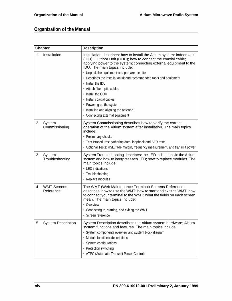
1 Installation Installation describes: how to install the Altium system: Indoor Unit (IDU), Outdoor Unit (ODU); how to connect the coaxial cable; applying power to the system; connecting external equipment to the IDU. The main topics include:• Unpack the equipment and prepare the site• Describes the installation kit and recommended tools and equipment• Install the IDU• Attach fiber optic cables• Install the ODU• Install coaxial cables• Powering up the system• Installing and aligning the antenna• Connecting external equipment
2 System Commissioning
System Commissioning describes how to verify the correct operation of the Altium system after installation. The main topics include:• Preliminary checks• Test Procedures: gathering data, loopback and BER tests• Optional Tests: RSL, fade margin, frequency measurement, and transmit power
3 System Troubleshooting
System Troubleshooting describes: the LED indications in the Altium system and how to interpret each LED; how to replace modules. The main topics include:• LED indications• Troubleshooting• Replace modules
4 WMT Screens Reference
The WMT (Web Maintenance Terminal) Screens Reference describes: how to use the WMT; how to start and exit the WMT; how to connect your terminal to the WMT; what the fields on each screen mean. The main topics include: • Overview• Connecting to, starting, and exiting the WMT• Screen reference
5 System Description System Description describes: the Altium system hardware; Altium system functions and features. The main topics include:• System components overview and system block diagram• Module functional descriptions• System configurations• Protection switching• ATPC (Automatic Transmit Power Control)
xiv PN 300-610012-001 Preliminary 2, January 1999

Chapter 1
Installation
This chapter provides information on: installing the Altium system Indoor Unit (IDU) and Outdoor Unit (ODU); connecting the coaxial cable; applying power to the system; aligning the antenna; and connecting external equipment to the IDU.
Overview
Altium system installation procedures are generally outlined as follows:
• Unpacking the equipment
• Preparing adequate rack space, appropriate power, and grounding
• Mounting the IDU
• Mounting the ODU
• Installing the coaxial cable
• Mounting and aligning the antenna
• Connecting external equipment
You may also need to use the Web Maintenance Terminal (WMT) to change or set the Altium system’s operating parameters. Refer to Chapter 4, WMT Screens Reference, for more information.
PN 300-610012-001 Preliminary 2, January 1999 Installation 1-1

Unpacking the Equipment Altium Microwave Radio System
Unpacking the Equipment
The tools required for unpacking the system equipment are:
• Utility knife
• Clean, flat working surface
Open the shipping containers, carefully remove the equipment and place on a clean, flat working surface. Save the shipping and packing material in case the equipment has to be returned.
Check the equipment and installation kits against the packing list to ensure that the equipment part numbers, parts, and ancillary equipment included in the shipment match what is specified on the packing list. If there are discrepancies between the packing list and the equipment received, contact the nearest sales representative.
Inspect the equipment for any type of shipping damage. If any part of the shipment is damaged, contact your nearest sales representative for repair or replacement instructions.
Packing ListVerify that the packing list accurately describes the contents of the shipped equipment. Shipments consist of an IDU and an installation kit in one container and an ODU in another container (Figure 1-1).
Figure 1-1. Unpacking the IDU and ODU
PackingList IDU
Installation Kit
ODU
0266
1 box
1 box
An Altium system ships in two containers.
1-2 Installation PN 300-610012-001 Preliminary 2, January 1999

Altium Microwave Radio System Preparing the Site
Preparing the Site
The installation site must have adequate rack space, power, and grounding.
Rack SpaceThe Altium IDU can be installed in a standard 19-in. (48 cm) rack and requires 3 rack units (Figure 1-2). A rack unit is 1.75-in. (4.5 cm) of vertical space.
Figure 1-2. Altium System Rack Space
PowerPower to the IDU must be in the range -40.5 to -72 VDC. Nominal input voltage is -48 VDC to -60 VDC. An external step-up power converter is required when the voltage is below -40.5 VDC.
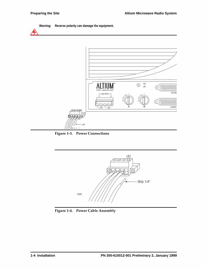
The battery supply connects to the Altium system through a four-conductor Phoenix connector. The polarity for the battery supply ground lead and negative leads is shown in Figure 1-3.
Each Signal Processor (SP) module, A for a nonprotected system, A and B for a protected system, requires a power connection. Each power connection requires that you assemble a power cable.
Note: The minimum cable size for the power cable is 12 AWG (2 mm).
Assemble the power cable for each power connection as follows:
1. Strip 1/4 in. (0.6 cm) insulation from the ends of each of the power leads you are connecting to the Altium system.
2. Insert each power lead as shown in Figure 1-4.
3. Secure each lead in the power connector by tightening the screw on top of the connectod.
B
A
ESD
3 RACKUNITS
0232
VF DATA
ALARMS
NMS/AUX 1
MAINT
NMS/AUX 1
NMS/AUX 2
STATUS
MAJ MIN ODU MAINT
PN 300-610012-001 Preliminary 2, January 1999 Installation 1-3
Preparing the Site Altium Microwave Radio System
Warning: Reverse polarity can damage the equipment.
Figure 1-3. Power Connections
Figure 1-4. Power Cable Assembly
B
ESD
VF/AU
CONTRA B
0268
Strip 1/4"
1-4 Installation PN 300-610012-001 Preliminary 2, January 1999

Altium Microwave Radio System Preparing the Site
GroundingProper grounding of equipment and structures is essential to prevent electrical damage to the Altium system.
Grounding of all equipment at a radio site is required. Without proper grounding, voltage potentials between components of the system can cause electrical damage when interconnecting cables are installed.
Note: Ground wires and hardware are not provided in the installation kit.
Grounding the IDU
The IDU is grounded through the mounting hardware to the equipment rack. The equipment rack must be connected to station or earth ground. Refer to Figure 1-5.
Figure 1-5. Grounding the IDU
0269
IDU is grounded through mounting hardware
Mounting rack must be connected to station or earth ground
PN 300-610012-001 Preliminary 2, January 1999 Installation 1-5

Preparing the Site Altium Microwave Radio System
Grounding the ODU
A suitable ground wire must connect the ODU ground lug (Figure 1-6) to an appropriate ground point on the antenna mounting or tower. This connection is site dependent. The surface of all ground wire contact points must be clean to ensure a low-resistance connection.
Figure 1-6. Grounding the ODU
ESD Protection
ESD (electrostatic discharge) can damage electronic components. Even if components remain functional, ESD can cause latent damage that results in premature failure. Personnel and equipment must be properly grounded.
Always wear proper ESD grounding straps during equipment installation, maintenance and repairs. Connect your ESD grounding strap to the connector shown in Figure 1-7.
Figure 1-7. ESD Protection
0235
Coaxial Cable TNC Connector
RSSI BNC Connector
Coaxial Cable TNC Connector
RSSI BNC Connector
A Side B Side
Ground Lug Ground Lug
B
A B
ESD
VF DATA
ALARMS
ESD Connector
1-6 Installation PN 300-610012-001 Preliminary 2, January 1999
Altium Microwave Radio System Installation Kit
Installation Kit
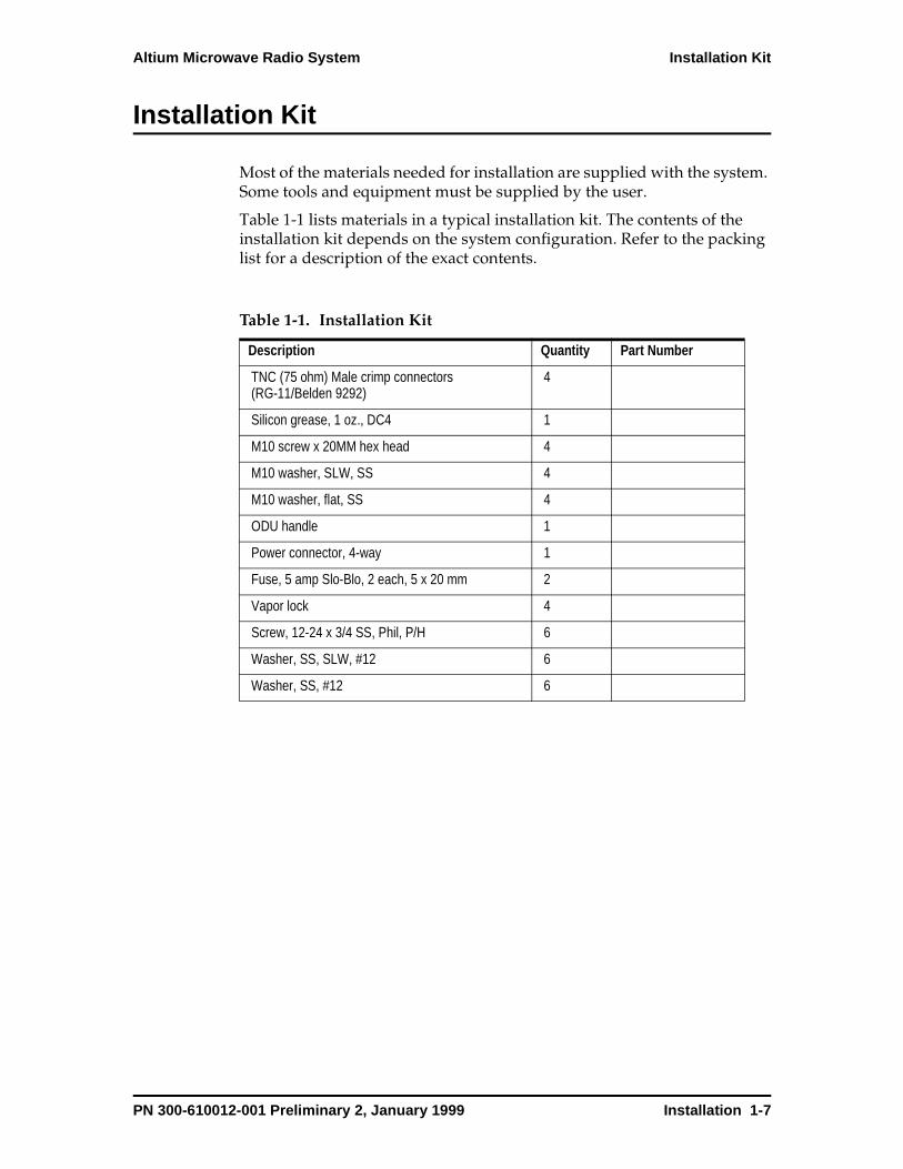
Most of the materials needed for installation are supplied with the system. Some tools and equipment must be supplied by the user.
Table 1-1 lists materials in a typical installation kit. The contents of the installation kit depends on the system configuration. Refer to the packing list for a description of the exact contents.
Table 1-1. Installation Kit
Description Quantity Part Number
TNC (75 ohm) Male crimp connectors (RG-11/Belden 9292)
4
Silicon grease, 1 oz., DC4 1
M10 screw x 20MM hex head 4
M10 washer, SLW, SS 4
M10 washer, flat, SS 4
ODU handle 1
Power connector, 4-way 1
Fuse, 5 amp Slo-Blo, 2 each, 5 x 20 mm 2
Vapor lock 4
Screw, 12-24 x 3/4 SS, Phil, P/H 6
Washer, SS, SLW, #12 6
Washer, SS, #12 6
PN 300-610012-001 Preliminary 2, January 1999 Installation 1-7
Recommended Tools and Test Equipment Altium Microwave Radio System
Recommended Tools and Test Equipment
In addition to the installation materials available from Digital Microwave Corporation, there are recommended user-supplied tools and test equipment:
• 11 mm (7/16-in.) end wrench or nut driver
• 14 mm (9/16-in.) end wrench or box wrench
• 19 mm (3/4-in.) end wrench or box wrench
• Torque wrench, 27 Newton-meters (20 foot-pounds)
• 14 mm (9/16-in.) crow-foot wrench adapter or socket for torque wrench
• 3/32-in. hex (Allen-head) driver
• Screwdriver, No. 2 Phillips
• Screwdriver, No. 2 flat blade (common)
• Crimp tool for RG-11 TNC connectors
• Digital voltmeter (DVM) for measuring RSSI (receive signal strength indicator) voltage during antenna alignment and checking for a short between the conductor and shield when making cables
• Portable (laptop) computer with a serial RS-232 communications port and cable or 10BaseT Ethernet port
• Telephone with FCC Class B electronic ringer, cable and RJ-11 modular telephone connectors at each end. Used for communicating over the engineering order wire (EOW) only if voice EOW is used.
• Optical pattern generator/checker (optional), 155 Mbps (STM-1/OC-3)
1-8 Installation PN 300-610012-001 Preliminary 2, January 1999
Altium Microwave Radio System Installing the IDU
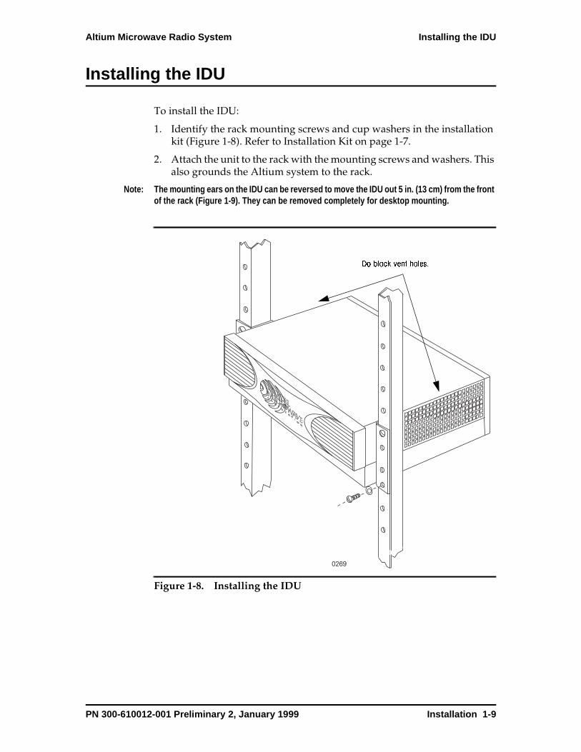
Installing the IDU
To install the IDU:
1. Identify the rack mounting screws and cup washers in the installation kit (Figure 1-8). Refer to Installation Kit on page 1-7.
2. Attach the unit to the rack with the mounting screws and washers. This also grounds the Altium system to the rack.
Note: The mounting ears on the IDU can be reversed to move the IDU out 5 in. (13 cm) from the front of the rack (Figure 1-9). They can be removed completely for desktop mounting.
Figure 1-8. Installing the IDU
0269
Do block vent holes.
PN 300-610012-001 Preliminary 2, January 1999 Installation 1-9

Installing the IDU Altium Microwave Radio System
Figure 1-9. Reversed Mounting Ears
0270
1-10 Installation PN 300-610012-001 Preliminary 2, January 1999

Altium Microwave Radio System Connecting Fiber Optic Cables to the Altium System
Connecting Fiber Optic Cables to the Altium System
STM-1/OC-3 data connects to the Altium system through multimode fiber-optic cables. The fiber-optic cables connect the optical access on the multiplexer to the SP module in the IDU. The connectors on the SP module are ST type.
Warning: Never look into the end of a fiber-optic cable.
To connect the fiber-optic cable to the Altium system:
1. Remove the front panel by undoing the four fasteners (Figure 1-10).
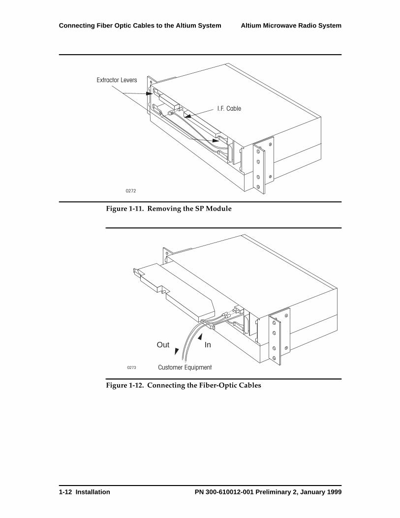
2. Remove the IF cable from the SP module (Figure 1-11).
3. Use the card extractor levers to unseat the SP module and slide it out (approximately 6 in. or 15 cm) until you can see the ST connector (Figure 1-12).
4. Connect the fiber-optic cables.
5. Reseat the SP module. Press the card extractor levers flat against the edge of the SP module.
6. Reconnect the IF cable to the SP module.
7. Route the fiber-optic cables through the cable access cutouts on the access panel (Figure 1-13).
8. Reinstall the front panel and secure it with the four fasteners.
Figure 1-10. Removing the Front Panel
B
A
ESD
0271
VF DATA
ALARMS
NMS/AUX 1
MAINT
NMS/AUX 1
NMS/AUX 2
STATUS
MAJ MIN ODU MAINT
Captured FastenersCaptured Fasteners
PN 300-610012-001 Preliminary 2, January 1999 Installation 1-11
Connecting Fiber Optic Cables to the Altium System Altium Microwave Radio System
Figure 1-11. Removing the SP Module
Figure 1-12. Connecting the Fiber-Optic Cables
0272
Extractor Levers
I.F. Cable
0273 Customer Equipment
InOut
1-12 Installation PN 300-610012-001 Preliminary 2, January 1999
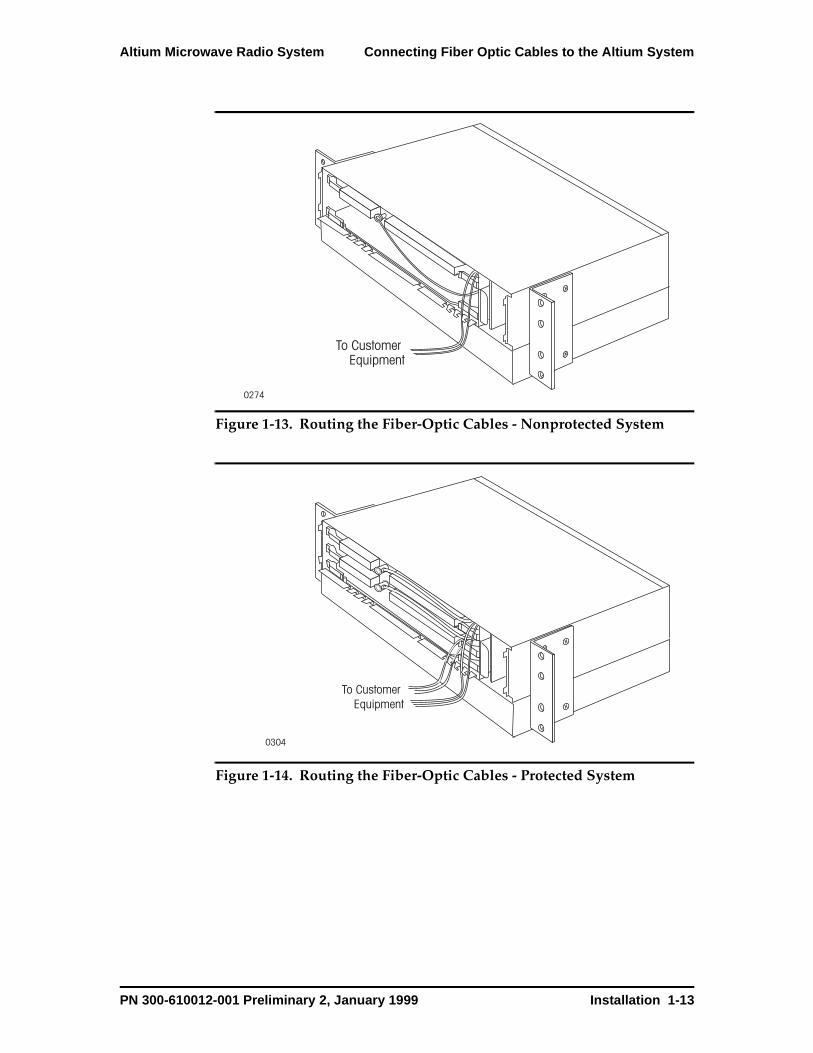
Altium Microwave Radio System Connecting Fiber Optic Cables to the Altium System
Figure 1-13. Routing the Fiber-Optic Cables - Nonprotected System
Figure 1-14. Routing the Fiber-Optic Cables - Protected System
0274
To Customer Equipment
0304
To Customer Equipment
PN 300-610012-001 Preliminary 2, January 1999 Installation 1-13

Installing the ODU Altium Microwave Radio System
Installing the ODU
There are four ODU mounting scenarios:
• Slip-fit with horizontal polarization
• Slip-fit with vertical polarization
• Space diversity with flexible waveguide
• Space diversity with flexible waveguide/Slip-fit with horizontal polarization
The ODU can be connected directly to the antenna using a Slip fit connector or connected remotely using flexible waveguide. Space diversity combines direct and remote mounted antennas.
The ODU can be offset mounted to the left or right. The offset refers to the antenna being mounted to one side or the other of the mounting pole. Whether an antenna is offset to the left or right is site dependent.
Note: Install the antenna and antenna mount according to the manufacturer’s installation instructions included with the antenna and mount assembly.
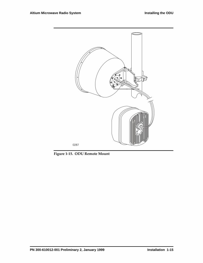
Remote Mount The ODU is mounted away from the antenna on a pipe or wall. There are two methods to mount the ODU to a pipe:
• Mounting the ODU to the same pipe as the antenna is mounted.
• Installing a separate pipe mounting kit specifically designed for the ODU remote mount.
There are also two methods to mount the ODU to a wall:
• Fastening the pipe mounting kit to a wall using lag bolts or other suitable fasteners.
• The plates in the pipe mounting kit can be fastened directly to the wall with lag bolts or other suitable fasteners.
With either wall-mount method, the plates attach to the ODU by the four threaded holes.
Flexible waveguide is used for the RF antenna interface with all remote mounting methods. Flexible waveguide is available in 24 in., 30 in., and 36 in. (60.7 cm, 76.2 cm and 91.4 cm) lengths.
Caution: If lubricant is used in the threaded holes in the ODU, avoid applying excessive amounts. An excess of lubricant can create undue pressure when compressed by the bolts resulting in damage to the ODU housing.
1-14 Installation PN 300-610012-001 Preliminary 2, January 1999
Altium Microwave Radio System Installing the ODU
Figure 1-15. ODU Remote Mount
0287
PN 300-610012-001 Preliminary 2, January 1999 Installation 1-15

Installing the ODU Altium Microwave Radio System
Horizontal Polarization
Figure 1-16. Horizontal Polarization
0317
Waveguide Spacer with "O"- Ring
Radio Bracket with fourM6 x 16mm HD Screws
Attach Radio using four sets ofM10 x 20mm Hex Head Bolts and
Washers supplied with Radio
Feed Receptacle with "O" - Ringsupplied with Feed
Reflector Plate
1-16 Installation PN 300-610012-001 Preliminary 2, January 1999
Altium Microwave Radio System Installing the ODU
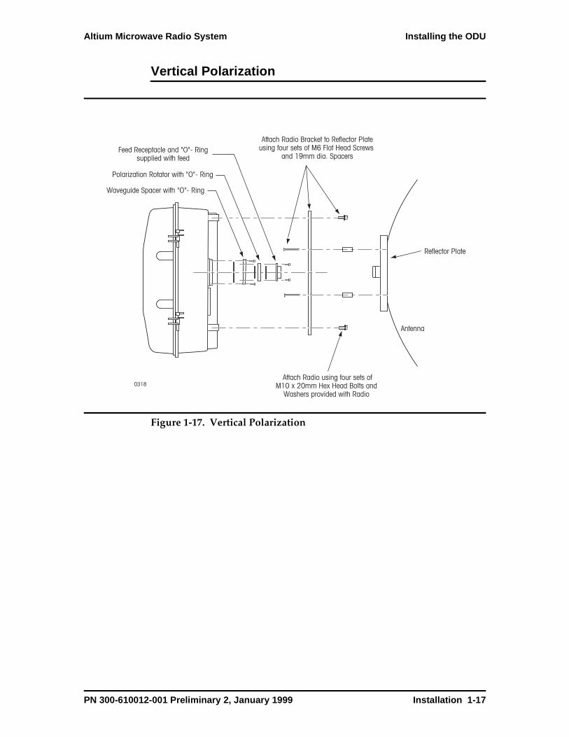
Vertical Polarization
Figure 1-17. Vertical Polarization
0318
Waveguide Spacer with "O"- Ring
Attach Radio Bracket to Reflector Plateusing four sets of M6 Flat Head Screws
and 19mm dia. Spacers
Reflector Plate
Attach Radio using four sets ofM10 x 20mm Hex Head Bolts and
Washers provided with Radio
Antenna
Polarization Rotator with "O"- Ring
Feed Receptacle and "O"- Ringsupplied with feed
PN 300-610012-001 Preliminary 2, January 1999 Installation 1-17
Installing the ODU Altium Microwave Radio System
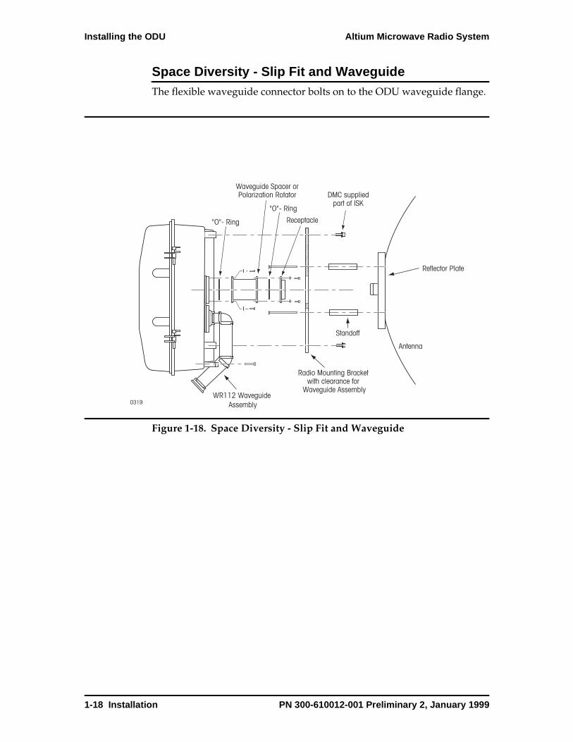
Space Diversity - Slip Fit and WaveguideThe flexible waveguide connector bolts on to the ODU waveguide flange.
Figure 1-18. Space Diversity - Slip Fit and Waveguide
0319
"O"- Ring
Radio Mounting Bracket with clearance for
Waveguide Assembly
Reflector Plate
Antenna
Waveguide Spacer orPolarization Rotator
"O"- Ring
Receptacle
DMC suppliedpart of ISK
Standoff
WR112 Waveguide Assembly
1-18 Installation PN 300-610012-001 Preliminary 2, January 1999

Altium Microwave Radio System Installing the ODU
Space Diversity - Flexible WaveguideSpace diversity requires two antennas each for the near and far ends (Figure 1-19). Each antenna is remote mounted to the ODU (connected to the ODU with flexible waveguide).
Figure 1-19. Space Diversity - Flexible Waveguide
0300
PN 300-610012-001 Preliminary 2, January 1999 Installation 1-19
Installing the ODU Altium Microwave Radio System
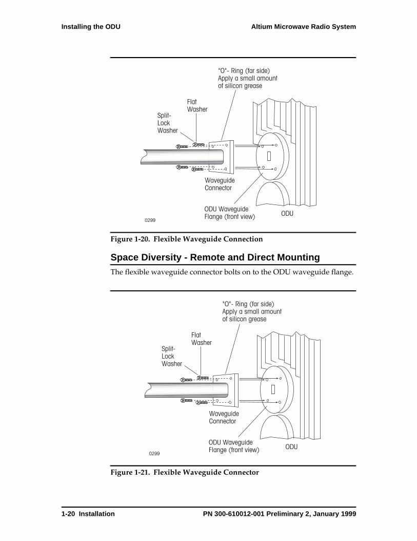
Figure 1-20. Flexible Waveguide Connection
Space Diversity - Remote and Direct MountingThe flexible waveguide connector bolts on to the ODU waveguide flange.
Figure 1-21. Flexible Waveguide Connector
0299
FlatWasher
Split-LockWasher
"O"- Ring (far side)Apply a small amount of silicon grease
ODU WaveguideFlange (front view)
WaveguideConnector
ODU
0299
FlatWasher
Split-LockWasher
"O"- Ring (far side)Apply a small amount of silicon grease
ODU WaveguideFlange (front view)
WaveguideConnector
ODU
1-20 Installation PN 300-610012-001 Preliminary 2, January 1999

Altium Microwave Radio System Installing the ODU
Offset ConfigurationThe ODU can be mounted offset either to the right or to the left of the mounting pole. The ODU cover can then be installed on either side of the ODU to accommodate either configuration. To reconfigure the ODU offset configuration, remove the washer from the top and bottom hinges. Lift the cover up and off the hinges. Rotate the cover so that it fits on the hinges on the other side. Replace the washers.
Figure 1-22. ODU Offset Configuration
0309
Washer
PN 300-610012-001 Preliminary 2, January 1999 Installation 1-21
Installing the IDU/ODU Coaxial Cable Altium Microwave Radio System
Installing the IDU/ODU Coaxial Cable
A 75-ohm coaxial cable connects the IDU to the ODU. The cable connects power to the ODU and allows data to flow between the IDU and ODU.
The IDU provides one TNC-female connector for each SP module. This connector is located on the Access Panel. The ODU connector is one TNC-female connector for each radio side. This connector is located on the bottom of the ODU.
Install one cable in a nonprotected system, two cables in a protected system.
Do not use cables with a copper-clad steel center conductor. The cables should be double- or triple-shielded. Figure 1-2 lists recommended coaxial cables.
• The recommended crimp-type TNC connectors are:
• For RG-6 (Belden 9248): 039-361312-001
• For RG-11 (Belden 9292): 039-361312-002
• The recommended crimping tools for TNC connectors are:
• For RG-6 (Belden 9248): 008-311000-026
• For RG-11 (Belden 9292): 008-311000-027
Note: If there is a conflict of information in this section with the information of the connector manufacturer, follow the procedures of the connector manufacturer.
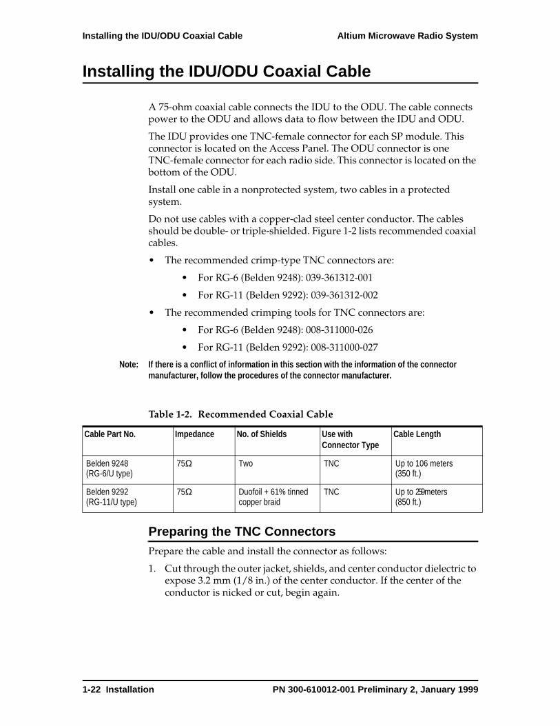
Preparing the TNC ConnectorsPrepare the cable and install the connector as follows:
1. Cut through the outer jacket, shields, and center conductor dielectric to expose 3.2 mm (1/8 in.) of the center conductor. If the center of the conductor is nicked or cut, begin again.
Table 1-2. Recommended Coaxial Cable
Cable Part No. Impedance No. of Shields Use with Connector Type
Cable Length
Belden 9248(RG-6/U type)
75Ω Two TNC Up to 106 meters (350 ft.)
Belden 9292 (RG-11/U type)
75Ω Duofoil + 61% tinned copper braid
TNC Up to 259 meters (850 ft.)
1-22 Installation PN 300-610012-001 Preliminary 2, January 1999
Altium Microwave Radio System Installing the IDU/ODU Coaxial Cable
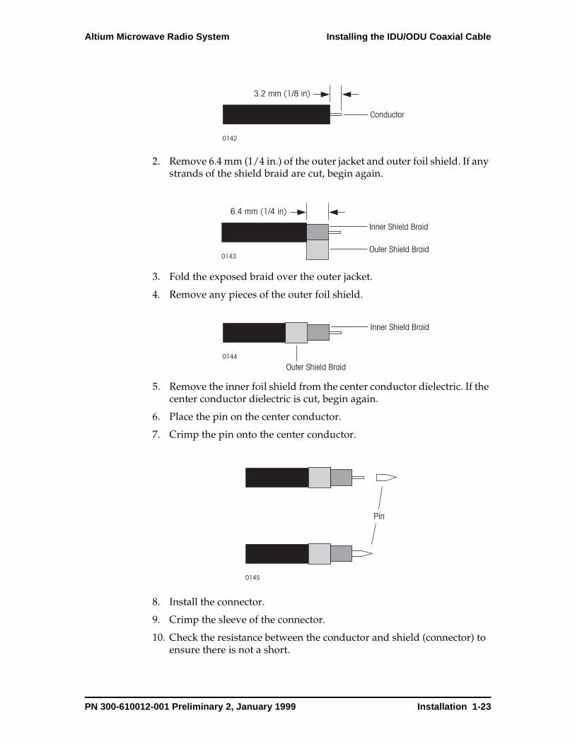
2. Remove 6.4 mm (1/4 in.) of the outer jacket and outer foil shield. If any strands of the shield braid are cut, begin again.
3. Fold the exposed braid over the outer jacket.
4. Remove any pieces of the outer foil shield.
5. Remove the inner foil shield from the center conductor dielectric. If the center conductor dielectric is cut, begin again.
6. Place the pin on the center conductor.
7. Crimp the pin onto the center conductor.
8. Install the connector.
9. Crimp the sleeve of the connector.
10. Check the resistance between the conductor and shield (connector) to ensure there is not a short.
3.2 mm (1/8 in)
0142
Conductor
6.4 mm (1/4 in)
0143
Inner Shield Braid
Outer Shield Braid
0144
Inner Shield Braid
Outer Shield Braid
0145
Pin
PN 300-610012-001 Preliminary 2, January 1999 Installation 1-23

Installing the IDU/ODU Coaxial Cable Altium Microwave Radio System
Coax Cable Service LoopNote: If installing a protected system, label each coaxial cable as A-side or B-side.
Route the coaxial cable from the ODU to the IDU through any pipes, grommets, or other openings. The cable is to be secured from end to end according to local regulations and guidelines. There must be enough cable (service loop) at each end of the cable run to accommodate connecting equipment.
Identifying A-side and B-side CablesIf the cables are not labelled, you can perform a resistance check to identify each cable.
Caution: Check that the coaxial cable is not connected to the IDU or ODU before starting this procedure.
1. Apply a short between the shield and the center conductor of one cable at ODU location.
2. With an ohmmeter at the IDU side of the cable, measure the resistance of each coaxial cable from the shield to center conductor. The cable that you applied the short to will have a much lower resistance than the other cable.
3. Label the identified cable as A at both ends. Label the other coaxial cable as B at both ends of the cable.
0146
Connector Sleeve Connector
1-24 Installation PN 300-610012-001 Preliminary 2, January 1999

Altium Microwave Radio System Installing the IDU/ODU Coaxial Cable
Connecting the Coaxial Cable This procedure describes how to connect the coaxial cables in a protected system. In a nonprotected system, the A-side of the IDU is connected to the A-side on the ODU.
The connectors for installation are listed in Table 1-3 and shown in Figure 1-23.
Figure 1-23. ODU TNC Connectors
To connect coaxial cables to the Altium system:
1. Install the protective cap on the RSSI connector of the ODU.
2. Check that the connectors of the coaxial cables have been labelled. One cable should have each of its connectors labelled A and the other cable should have each of its connectors labelled B.
3. At the ODU, connect the coaxial cable labelled A to the A connector. Connect the coaxial cable labelled B to the B connector.
4. Apply the Vapor Wrap from the installation kit to the TNC connector on the ODU, fully covering the connector to add another weather barrier.
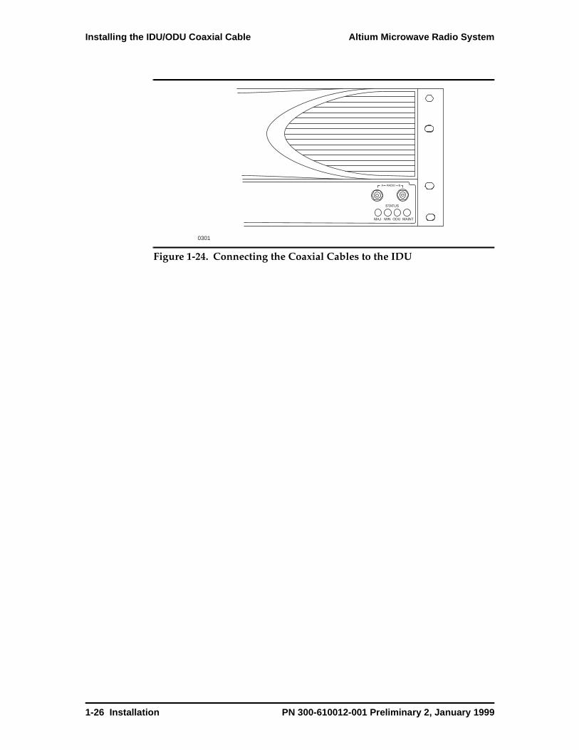
5. At the IDU, connect the coaxial cable labelled A to the A connector (Figure 1-24). Connect the coaxial cable labelled B to the B connector.
Table 1-3. ODU Connectors
Connector Type Description
TNC ODU to IDU cable connector.
BNC Access point for monitoring RSSI (AGC) voltage during system set-up or system maintenance.
Waveguide Flange Antenna to ODU interface. Waveguide types, flanges and screw sizes vary with the frequency band of the radio.
Ground Lug Connection to earth or station ground on tower or other mounting structure.
0235
Coaxial Cable TNC Connector
RSSI BNC Connector
Coaxial Cable TNC Connector
RSSI BNC Connector
A Side B Side
Ground Lug Ground Lug
PN 300-610012-001 Preliminary 2, January 1999 Installation 1-25
Installing the IDU/ODU Coaxial Cable Altium Microwave Radio System
Figure 1-24. Connecting the Coaxial Cables to the IDU
0301
STATUS
MAJ MIN ODU MAINT
1-26 Installation PN 300-610012-001 Preliminary 2, January 1999
Altium Microwave Radio System Powering Up
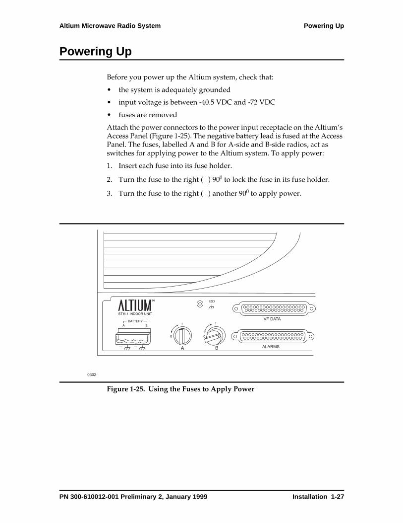
Powering Up
Before you power up the Altium system, check that:
• the system is adequately grounded
• input voltage is between -40.5 VDC and -72 VDC
• fuses are removed
Attach the power connectors to the power input receptacle on the Altium’s Access Panel (Figure 1-25). The negative battery lead is fused at the Access Panel. The fuses, labelled A and B for A-side and B-side radios, act as switches for applying power to the Altium system. To apply power:
1. Insert each fuse into its fuse holder.
2. Turn the fuse to the right ( ) 900 to lock the fuse in its fuse holder.
3. Turn the fuse to the right ( ) another 900 to apply power.
Figure 1-25. Using the Fuses to Apply Power
B
A B
0302
ESD
VF DATA
ALARMS
PN 300-610012-001 Preliminary 2, January 1999 Installation 1-27
Aligning the Antenna Altium Microwave Radio System
Aligning the Antenna
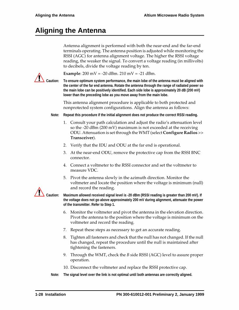
Antenna alignment is performed with both the near-end and the far-end terminals operating. The antenna position is adjusted while monitoring the RSSI (AGC) for antenna alignment voltage. The higher the RSSI voltage reading, the weaker the signal. To convert a voltage reading (in millivolts) to decibels, divide the voltage reading by ten.
Example: 200 mV = -20 dBm. 210 mV = -21 dBm.
Caution: To ensure optimum system performance, the main lobe of the antenna must be aligned with the center of the far end antenna. Rotate the antenna through the range of radiated power so the main lobe can be positively identified. Each side lobe is approximately 20 dB (200 mV) lower than the preceding lobe as you move away from the main lobe.
This antenna alignment procedure is applicable to both protected and nonprotected system configurations. Align the antenna as follows:
Note: Repeat this procedure if the initial alignment does not produce the correct RSSI reading.
1. Consult your path calculation and adjust the radio’s attenuation level so the -20 dBm (200 mV) maximum is not exceeded at the receiving ODU. Attenuation is set through the WMT (select Configure Radios >> Transceiver).
2. Verify that the IDU and ODU at the far end is operational.
3. At the near-end ODU, remove the protective cap from the RSSI BNC connector.
4. Connect a voltmeter to the RSSI connector and set the voltmeter to measure VDC.
5. Pivot the antenna slowly in the azimuth direction. Monitor the voltmeter and locate the position where the voltage is minimum (null) and record the reading.
Caution: Maximum allowed received signal level is -20 dBm (RSSI reading is greater than 200 mV). If the voltage does not go above approximately 200 mV during alignment, attenuate the power of the transmitter. Refer to Step 1.
6. Monitor the voltmeter and pivot the antenna in the elevation direction. Pivot the antenna to the position where the voltage is minimum on the voltmeter and record the reading.
7. Repeat these steps as necessary to get an accurate reading.
8. Tighten all fasteners and check that the null has not changed. If the null has changed, repeat the procedure until the null is maintained after tightening the fasteners.
9. Through the WMT, check the B side RSSI (AGC) level to assure proper operation.
10. Disconnect the voltmeter and replace the RSSI protective cap.
Note: The signal level over the link is not optimal until both antennas are correctly aligned.
1-28 Installation PN 300-610012-001 Preliminary 2, January 1999

Altium Microwave Radio System Aligning the Antenna
Figure 1-26. RSSI Connector (Protected ODU shown)
Figure 1-27. Antenna Alignment
0237
RSSI A RSSI B
PN 300-610012-001 Preliminary 2, January 1999 Installation 1-29

Connecting External Equipment Altium Microwave Radio System
Connecting External Equipment
You can connect various types of equipment and applications to the Altium system through industry standard connectors on the Access Panel (Figure 1-28). You can connect:
• the WMT workstation through the Ethernet hub or Maint connector
• the Handset through the Handset connector
• to a LAN through the Ethernet hub
• Data applications through the VF/Aux Data connector
• Voice applications through the VF/Aux Data connector
• Alarm applications through the Control/Alarms connector
This section does not discuss the power connector (Power on page 1-3), fuses (Power on page 1-3), the ESD connector (Grounding on page 1-5), or the coaxial cable connectors (Connecting the Coaxial Cable on page 1-25).
Figure 1-28. Access Panel Connectors
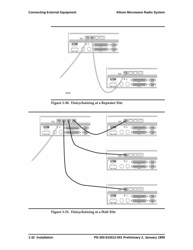
Ethernet Hub Four RJ-45 connectors provide 10 Base-T Ethernet access (Figure 1-29). The Ethernet data rate is 10 Mbps on the bridge ports and 128 Kbps across the link. The connector on the first port (Connector 1) provides a Media Dependent Interface (MDI-X), a standard interface for unshielded twisted pair (UTP) cable. MDI-X provides the crossover function that is necessary when chaining Ethernet hubs together. The connectors for ports 2, 3, and 4 are wired as an MDI interface. The pinout functions are opposite that of port 1 (Table 1-4). The MDI-X interface allows you to use a straight-through cable to chain Ethernet hubs together: you connect an MDI-X port to an MDI port. To use a crossover cable, connect an MDI-X port to an MDI-X port or connect an MDI port to an MDI port (Figure 1-30).
When daisychaining Altium systems together through the Ethernet hub,
0286
Signal Processor A
Signal Processor B
ISAC
Fiber Connectors Fan
B
A
ESD
VF/AUX DATA
CONTROL/ALARMS
NMS/AUX 1
MAINT
NMS/AUX 2
NMS/AUX 3
STATUS
MAJ MIN ODU MAINT
Handset Connector1 2 3 4
10BaseT Ethernet Hub
1-30 Installation PN 300-610012-001 Preliminary 2, January 1999

Altium Microwave Radio System Connecting External Equipment
remember that:
• Maximum cable length including drop leads is 100 meters
• Each cable provides a point-to-point connection
• Each cable is a single segment
• The cable must be between 85 ohms and 110 ohms
• The cable are terminated with RJ45 connectors
Figure 1-29. Ethernet Hub Pin Locations
Table 1-4. Ethernet Hub Pinouts
Pin Connector 1 (MDI-X) I/O Connectors 2, 3, 4 (MDI) I/O
1 Ethernet transmit data + I Ethernet receive data + O
2 Ethernet transmit data - I Ethernet receive data - O
3 Ethernet receive data + O Ethernet transmit data + I
4 No Connection - No Connection -
5 No Connection - No Connection -
6 Ethernet receive data - O Ethernet transmit data - I
7 No Connection - No Connection -
8 No Connection - No Connection -
0284
1 2 3 4
1 8 1 8 1 8 1 8
PN 300-610012-001 Preliminary 2, January 1999 Installation 1-31
Connecting External Equipment Altium Microwave Radio System
Figure 1-30. Daisychaining at a Repeater Site
Figure 1-31. Daisychaining at a Hub Site
0308
ISAC
B
A
ESD
VF DATA
ALARMS
NMS/AUX 1
MAINT
ISAC
B
A
ESD
VF DATA
ALARMS
NMS/AUX 1
MAINT
ISAC
B
A
ESD
VF DATA
ALARMS
NMS/AUX 1
MAINT
ISAC
B
A
ESD
VF DATA
ALARMS
NMS/AUX 1
MAINT
ISAC
B
A
ESD
VF DATA
ALARMS
NMS/AUX 1
MAINT
ISAC
B
A
ESD
VF DATA
ALARMS
NMS/AUX 1
MAINT
1-32 Installation PN 300-610012-001 Preliminary 2, January 1999

Altium Microwave Radio System Connecting External Equipment
Handset ConnectorThe engineering orderwire (EOW) handset interface is an RJ-11, six-wire modular jack located on the ISAC (Table 1-5 and Table 1-32). The speaker on the ISAC module provides ringing for the handset.
Figure 1-32. Handset RJ-11 Connector
Table 1-5. Handset RJ-11 Connector Pinouts
Pin I/O Function
1 No Connection No Connection
2 No Connection No Connection
3 I/O Orderwire transmit/receive, tip
4 I/O Orderwire transmit/receive, ring
5 No Connection No Connection
6 No Connection No Connection
0285
1 6
PN 300-610012-001 Preliminary 2, January 1999 Installation 1-33
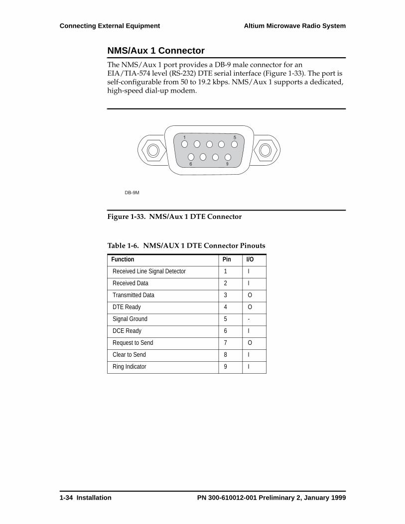
Connecting External Equipment Altium Microwave Radio System
NMS/Aux 1 ConnectorThe NMS/Aux 1 port provides a DB-9 male connector for an EIA/TIA-574 level (RS-232) DTE serial interface (Figure 1-33). The port is self-configurable from 50 to 19.2 kbps. NMS/Aux 1 supports a dedicated, high-speed dial-up modem.
Figure 1-33. NMS/Aux 1 DTE Connector
Table 1-6. NMS/AUX 1 DTE Connector Pinouts
Function Pin I/O
Received Line Signal Detector 1 I
Received Data 2 I
Transmitted Data 3 O
DTE Ready 4 O
Signal Ground 5 -
DCE Ready 6 I
Request to Send 7 O
Clear to Send 8 I
Ring Indicator 9 I
DB-9M
1
9
5
6
1-34 Installation PN 300-610012-001 Preliminary 2, January 1999
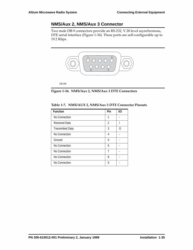
Altium Microwave Radio System Connecting External Equipment
NMS/Aux 2, NMS/Aux 3 Connector Two male DB-9 connectors provide an RS-232, V.28 level asynchronous, DTE serial interface (Figure 1-34). These ports are self-configurable up to 19.2 Kbps.
Figure 1-34. NMS/Aux 2, NMS/Aux 3 DTE Connectors
Table 1-7. NMS/AUX 2, NMS/Aux 3 DTE Connector Pinouts
Function Pin I/O
No Connection 1 -
Received Data 2 I
Transmitted Data 3 O
No Connection 4 -
Ground 5 -
No Connection 6 -
No Connection 7 -
No Connection 8 -
No Connection 9 -
DB-9M
1
9
5
6
PN 300-610012-001 Preliminary 2, January 1999 Installation 1-35

Connecting External Equipment Altium Microwave Radio System
MAINT Connector A DB-9 female connector provides an RS-232, V.28 level asynchronous, DCE serial interface that is self-configurable from 75 bps to 115200 bps (Figure 1-35). The WMT connects to the MAINT connector.
Figure 1-35. Maint DCE Connector
Table 1-8. Maint DCE Connector Pinouts
Function Pin I/O
No Connection 1 -
Received Data 2 O
Transmitted Data 3 I
No Connection 4 -
Ground 5 -
No Connection 6 -
No Connection 7 -
No Connection 8 -
No Connection 9 -
DB-9F
1
9
5
6
1-36 Installation PN 300-610012-001 Preliminary 2, January 1999
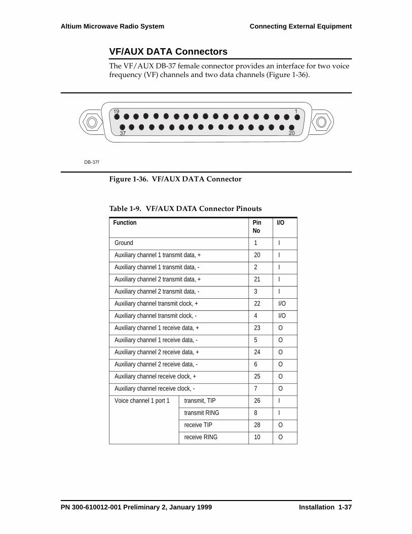
Altium Microwave Radio System Connecting External Equipment
VF/AUX DATA ConnectorsThe VF/AUX DB-37 female connector provides an interface for two voice frequency (VF) channels and two data channels (Figure 1-36).
Figure 1-36. VF/AUX DATA Connector
Table 1-9. VF/AUX DATA Connector Pinouts
Function Pin No
I/O
Ground 1 I
Auxiliary channel 1 transmit data, + 20 I
Auxiliary channel 1 transmit data, - 2 I
Auxiliary channel 2 transmit data, + 21 I
Auxiliary channel 2 transmit data, - 3 I
Auxiliary channel transmit clock, + 22 I/O
Auxiliary channel transmit clock, - 4 I/O
Auxiliary channel 1 receive data, + 23 O
Auxiliary channel 1 receive data, - 5 O
Auxiliary channel 2 receive data, + 24 O
Auxiliary channel 2 receive data, - 6 O
Auxiliary channel receive clock, + 25 O
Auxiliary channel receive clock, - 7 O
Voice channel 1 port 1 transmit, TIP 26 I
transmit RING 8 I
receive TIP 28 O
receive RING 10 O
20
DB-37f
1
37
19
PN 300-610012-001 Preliminary 2, January 1999 Installation 1-37
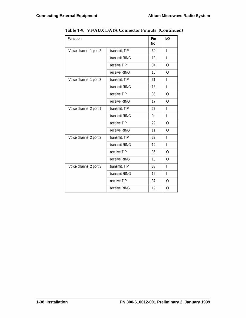
Connecting External Equipment Altium Microwave Radio System
Voice channel 1 port 2 transmit, TIP 30 I
transmit RING 12 I
receive TIP 34 O
receive RING 16 O
Voice channel 1 port 3 transmit, TIP 31 I
transmit RING 13 I
receive TIP 35 O
receive RING 17 O
Voice channel 2 port 1 transmit, TIP 27 I
transmit RING 9 I
receive TIP 29 O
receive RING 11 O
Voice channel 2 port 2 transmit, TIP 32 I
transmit RING 14 I
receive TIP 36 O
receive RING 18 O
Voice channel 2 port 3 transmit, TIP 33 I
transmit RING 15 I
receive TIP 37 O
receive RING 19 O
Table 1-9. VF/AUX DATA Connector Pinouts (Continued)
Function Pin No
I/O
1-38 Installation PN 300-610012-001 Preliminary 2, January 1999
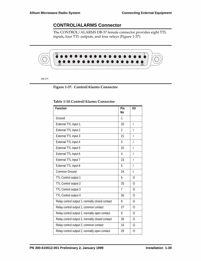
Altium Microwave Radio System Connecting External Equipment
CONTROL/ALARMS ConnectorThe CONTROL/ALARMS DB-37 female connector provides eight TTL inputs, four TTL outputs, and four relays (Figure 1-37).
Figure 1-37. Control/Alarms Connector
Table 1-10.Control/Alarms Connector
Function Pin No
I/O
Ground 1
External TTL input 1, 20 I
External TTL input 2 2 I
External TTL input 3 21 I
External TTL input 4 3 I
External TTL input 5 22 I
External TTL input 6 4 I
External TTL input 7 23 I
External TTL input 8 5 I
Common Ground 24 I
TTL Control output 1 6 O
TTL Control output 2 25 O
TTL Control output 3 7 O
TTL Control output 4 26 O
Relay control output 1, normally closed contact 8 O
Relay control output 1, common contact 27 O
Relay control output 1, normally open contact 9 O
Relay control output 2, normally closed contact 28 O
Relay control output 2, common contact 10 O
Relay control output 2, normally open contact 29 O
20
DB-37f
1
37
19
PN 300-610012-001 Preliminary 2, January 1999 Installation 1-39
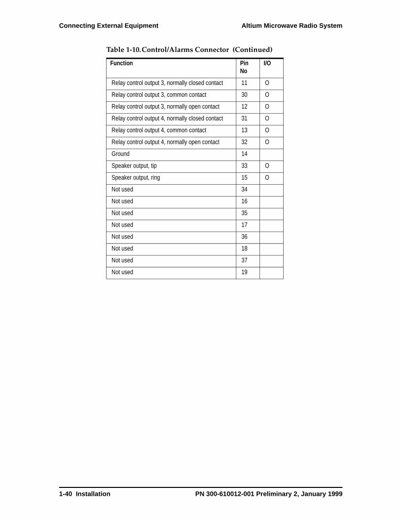
Connecting External Equipment Altium Microwave Radio System
Relay control output 3, normally closed contact 11 O
Relay control output 3, common contact 30 O
Relay control output 3, normally open contact 12 O
Relay control output 4, normally closed contact 31 O
Relay control output 4, common contact 13 O
Relay control output 4, normally open contact 32 O
Ground 14
Speaker output, tip 33 O
Speaker output, ring 15 O
Not used 34
Not used 16
Not used 35
Not used 17
Not used 36
Not used 18
Not used 37
Not used 19
Table 1-10.Control/Alarms Connector (Continued)
Function Pin No
I/O
1-40 Installation PN 300-610012-001 Preliminary 2, January 1999
Chapter 2
System Commissionin g
This chapter provides information on verifying the correct operation of the Altium system after installation.
Overview
System commissioning testing verifies proper operation of a newly installed DMC Altium radio system. This chapter provides testing procedures to insure the radio system is performing according to specifications. In some cases, more extensive testing (optional) may be necessary as dictated by local requirements. These test procedures are also provided. It is assumed that antenna alignment is complete and there are no system alarms.
Note: In many installations the Altium ODU is mounted directly on the antenna with a Slip-fit connector. Performing the optional commissioning tests are not always practical and are left to the discretion of the user.
Tests Performed• Local and remote loopbacks
• RSSI measurement
• Fade margin calculation
• Bit error performance
• Voltage checks
• TX power (checked with WMT)
• Frequency check (checked with WMT)
PN 300-610012-001 Preliminary 2, January 1999 System Commissioning 2-1

Preliminary Checks Altium Microwave Radio System
Required Test Equipment• Laptop computer
• Optical STM-1/OC-3 Bit Error Analyzer
• Digital voltmeter (DVM)
Optional TestsOptional tests require the following test equipment:
• Fade margin
• TX power
• Frequency check
• Receive signal level measurement
Optional Test Equipment• Power meter
• Frequency counter
• Variable Vane attenuator (0-50 dB)
• Necessary waveguide-SMA transitions, cables, screws and nuts
Preliminary Checks
Preliminary checks are intended to visually inspect and record the state of the Altium installation before you begin the commissioning tests. Check the following:
1. Visually inspect all equipment for obvious physical damage that occurred during the installation. (Minor paint scratches can be expected.)
2. Make sure all equipment and cabling is tightly secured and properly dressed.
3. Equipment has been properly grounded.
Note any discrepancies in the Notes section of the field commissioning form.
2-2 System Commissioning PN 300-610012-001 Preliminary 2, January 1999

Altium Microwave Radio System Test Procedures
Test Procedures
Before you begin these test procedures make sure you have all the required test equipment and accessories. These procedures are written assuming you are commissioning an MHSB 1+1 system. You might need to adjust these procedures to accommodate your particular system configuration. Use the Altium System Field Commissioning Form, located at the end of this chapter, to record system data and test results. Make copies of this form - do not use the original. Some tests require viewing certain WMT screens. Refer to Chapter 4, WMT Screens Reference, for more information.
Customer InformationOn the Altium System Field Commissioning Form, record the Customer Information in the appropriate section of the form. Refer to Altium System Field Commissioning Form on page 2-13.
Test Data
Input DC Voltage
Using a DVM, measure and record the input DC voltage at the power connector on the front of the IDU panel. Record the reading.
WMT RSSI
On the WMT, go to the Events & Performance screen and select RSSI. Record the reading. See RSSI on page 4-64.
WMT TX Power
On the WMT, go to the Transceiver Configuration screen. Record the reading. See Transceiver Configuration on page 4-52.
WMT TX/RX Frequency
On the WMT, go to the Synthesizer Configuration screen. Record the reading. See Synthesizer Configuration on page 4-50.
Calculated Fade Margin
Subtract the WMT RSSI reading from the Altium receiver threshold specification and record this number on the commissioning form.
Example: The WMT RSSI displayed a reading of –38dBm. The Altium receiver specification is –69dBm at 10-6. Subtracting 38 from 69 results in a calculated fade margin of 31dB. (Receiver specification depends on the radio frequency and bit rate.)
PN 300-610012-001 Preliminary 2, January 1999 System Commissioning 2-3
Test Procedures Altium Microwave Radio System
Loopback TestsThe loopback test checks the operation of the entire radio system. These tests can substitute for BER tests using external BER test set if such a test set is not available.
Local IF Loopback
1. Go to the loopback section on the WMT.
2. Select SP-A.
3. Select Local IF loopback.
4. Select Tributary 1.
5. Click Run Test.
6. Run the test for the required amount of time, then click Stop Test.
7. Note and record the number of errors on the commissioning form.
8. Repeat the test sequence for SP-B.
9. Repeat the test sequence for SP-A & SP-B at the other end of the link.
Remote LIU Loopback
1. Go to the Locking Control screen on the WMT. See Locking Controls Screen on page 4-72.
2. Select the A-side RF TX & RX and the SP RX selections at both ends of the link.
3. Go to the loop back section on the WMT.
4. Select Remote LIU loop back.
5. Select Tributary 1.
6. Click Run Test.
7. Run the test for the required amount of time then click Stop Test.
8. Note and record the number of errors on the commissioning form.
9. Select the B-side RF TX & RX and the SP RX selections at both ends of the link.
10. Go to the loop back section on the WMT.
11. Select Remote LIU loopback.
12. Select Tributary 1.
13. Click Run Test.
14. Run the test for the required amount of time then click Stop Test.
15. Note and record the number of errors on the commissioning form.
Note: It is not necessary to repeat these steps from the other end of the link.
2-4 System Commissioning PN 300-610012-001 Preliminary 2, January 1999
Altium Microwave Radio System Test Procedures
Bit Error Tests1. Connect a BERTS test set to the SP-A optical connections at each end of
the link. If only one BERT test set is available, a cable can be used to loop back the optical TX & RX at one end of the link. (Check installation section in manual for exact location.)
2. Select the A-side RF TX & RX and the SP RX selections at both ends of the link.
3. Run the test for required amount of time.
4. Record the test time and number of errors on the commissioning form.
5. Connect a BERTS test set to the SP-B optical connections at each end of the link. If only one BERT test set is available, a cable can be used to loop back the optical TX & RX at one end of the link.
6. Select the B-side RF TX & RX and the SP RX selections at both ends of the link.
7. Run the test for required amount of time.
8. Record the test time and number of errors on the commissioning form.
This completes the normal commissioning tests for the Altium radio system. If all tests have met specified parameters, your system is now ready to have traffic connected. If any tests have failed to meet specifications, consult the troubleshooting section of this manual for assistance (Chapter 3, System Troubleshooting). If further help is required, contact DMC customer service.
PN 300-610012-001 Preliminary 2, January 1999 System Commissioning 2-5
Optional Tests Altium Microwave Radio System
Optional Tests
Note: In many installations the Altium ODU is mounted directly on the antenna with a slip fit connector. Performing the optional commissioning tests is not always practical and are left to the discretion of the user.
Receive Signal Level (RSL)Refer to the test setup shown in Figure 2-1.
1. Measure and record the Receive Signal Level on the commissioning form.
Note: It is not necessary to repeat these steps from the other end of the link.
Fade Margin TestRefer to the test setup shown in Figure 2-2.
1. To connect SMA cables and the variable vane attenuator (AT1), first connect the ODU end of SMA cable B to the power meter. Set AT1 to 0 dB attenuation.
2. Take this measurement and subtract this reading from the RSL reading taken in the RSL test. This is the loss through SMA cables A and B plus AT1.
Example: RSL test measured a –38 dBm. Measurement at SMA cable B is –41 dBm. 38 from 41 is a 3 dB loss through the test set up.
3. Connect SMA cables and AT1.
4. Connect the BERTS test set to the on line SP module.
5. Slowly insert attenuation with AT1.
6. Continue until the BERTS test set indicates a BER rate of 10-6.
7. Note the attenuation setting on AT1.
8. Add the test set up loss calculated in Step 2 to the attenuation setting on AT1. This is the actual fade margin.
Example: Step 2 shows a 3 dB test set up loss. AT1 shows 28 dB of attenuation. Adding 28 to the test set up loss (3 dB) shows a fade margin of 31 dB.
Note: The optional fade margin test should be within +/- 4 dB of the calculated fade margin noted in the Test Data section of the commissioning form. It is not necessary to repeat these steps from the other end of the link.
2-6 System Commissioning PN 300-610012-001 Preliminary 2, January 1999
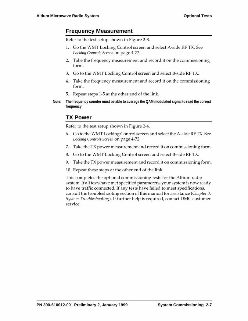
Altium Microwave Radio System Optional Tests
Frequency MeasurementRefer to the test setup shown in Figure 2-3.
1. Go the WMT Locking Control screen and select A-side RF TX. See Locking Controls Screen on page 4-72.
2. Take the frequency measurement and record it on the commissioning form.
3. Go to the WMT Locking Control screen and select B-side RF TX.
4. Take the frequency measurement and record it on the commissioning form.
5. Repeat steps 1-5 at the other end of the link.
Note: The frequency counter must be able to average the QAM modulated signal to read the correct frequency.
TX PowerRefer to the test setup shown in Figure 2-4.
6. Go to the WMT Locking Control screen and select the A-side RF TX. See Locking Controls Screen on page 4-72.
7. Take the TX power measurement and record it on commissioning form.
8. Go to the WMT Locking Control screen and select B-side RF TX.
9. Take the TX power measurement and record it on commissioning form.
10. Repeat these steps at the other end of the link.
This completes the optional commissioning tests for the Altium radio system. If all tests have met specified parameters, your system is now ready to have traffic connected. If any tests have failed to meet specifications, consult the troubleshooting section of this manual for assistance (Chapter 3, System Troubleshooting). If further help is required, contact DMC customer service.
PN 300-610012-001 Preliminary 2, January 1999 System Commissioning 2-7

Optional Tests Altium Microwave Radio System
Figure 2-1. Test Setup - Received Signal Level
Signal Module
Signal Module
ISAC Module
B
A
ESD
VF DATA
ALARMS
NMS/AUX 1
MAINT
NMS/AUX 1
NMS/AUX 2
STATUS
MAJ MIN ODU MAINT
Fan
Signal Module
Signal Module
ISAC Module
A
B
ESD
VF DATA
ALARMS
NMS/AUX 1
MAINT
NMS/AUX 1
NMS/AUX 2
STATUS
MAJ MIN ODU MAINT
Fan
Altium ODUODU, Prot. Waveguide-SMA
transition (4)
RG-6 Cables
Altium IDU
WMT Altium IDU
BERTS
to SP module under test
RG-6 Cables
Altium ODU
PowerMeter
PowerSensor
SMA Cable
Bit Error RateTest Set
0313
Remote Local
2-8 System Commissioning PN 300-610012-001 Preliminary 2, January 1999

Altium Microwave Radio System Optional Tests
Figure 2-2. Test Setup - Fade Margin
Signal Module
Signal Module
ISAC Module
B
A
ESD
VF DATA
ALARMS
NMS/AUX 1
MAINT
NMS/AUX 1
NMS/AUX 2
STATUS
MAJ MIN ODU MAINT
Fan
Signal Module
Signal Module
ISAC Module
A
B
ESD
VF DATA
ALARMS
NMS/AUX 1
MAINT
NMS/AUX 1
NMS/AUX 2
STATUS
MAJ MIN ODU MAINT
Fan
Altium ODUODU, Prot. Waveguide-SMA
transition (4)
RG-6 Cables
Altium IDU
WMT Altium IDU
BERTS
to SP module under test
RG-6 Cables
Altium ODU
PowerMeter
Power Sensor
AT1
SMA Cable A
Bit Error RateTest Set
0312
Remote Local
PN 300-610012-001 Preliminary 2, January 1999 System Commissioning 2-9

Optional Tests Altium Microwave Radio System
Figure 2-3. Test Setup - Frequency Measurement
Signal Module
Signal Module
ISAC Module
B
A
ESD
VF DATA
ALARMS
NMS/AUX 1
MAINT
NMS/AUX 1
NMS/AUX 2
STATUS
MAJ MIN ODU MAINT
Fan
Signal Module
Signal Module
ISAC Module
A
B
ESD
VF DATA
ALARMS
NMS/AUX 1
MAINT
NMS/AUX 1
NMS/AUX 2
STATUS
MAJ MIN ODU MAINT
Fan
Altium ODUODU, Prot. Waveguide-SMA
transition (4)
RG-6 Cables
Altium IDU
WMT Altium IDU
BERTS
to SP module under test
RG-6 Cables
Altium ODUFrequency Counter
SMA Cable
Bit Error RateTest Set
0315
Remote Local
7.775.00
2-10 System Commissioning PN 300-610012-001 Preliminary 2, January 1999
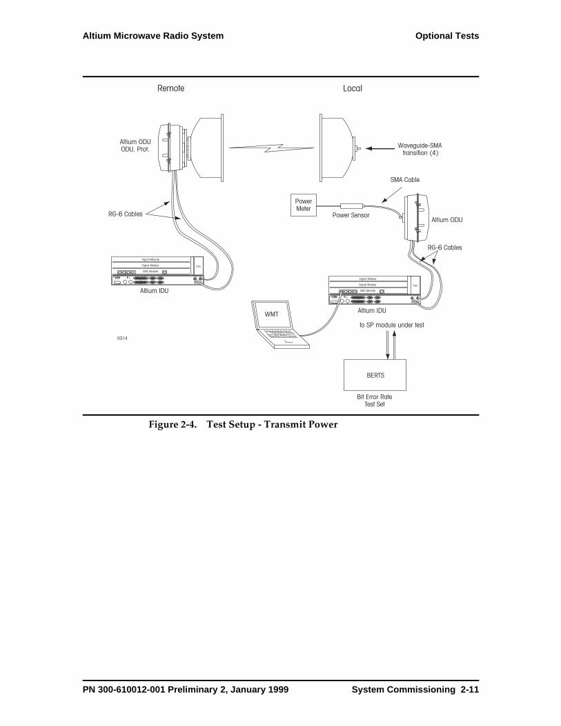
Altium Microwave Radio System Optional Tests
Figure 2-4. Test Setup - Transmit Power
Signal Module
Signal Module
ISAC Module
B
A
ESD
VF DATA
ALARMS
NMS/AUX 1
MAINT
NMS/AUX 1
NMS/AUX 2
STATUS
MAJ MIN ODU MAINT
Fan
Signal Module
Signal Module
ISAC Module
A
B
ESD
VF DATA
ALARMS
NMS/AUX 1
MAINT
NMS/AUX 1
NMS/AUX 2
STATUS
MAJ MIN ODU MAINT
Fan
Altium ODUODU, Prot. Waveguide-SMA
transition (4)
RG-6 Cables
Altium IDU
WMT Altium IDU
BERTS
to SP module under test
RG-6 Cables
Altium ODU
PowerMeter
Power Sensor
SMA Cable
Bit Error RateTest Set
0314
Remote Local
PN 300-610012-001 Preliminary 2, January 1999 System Commissioning 2-11

Optional Tests Altium Microwave Radio System
2-12 System Commissioning PN 300-610012-001 Preliminary 2, January 1999
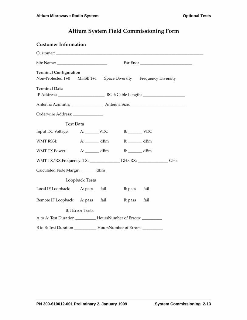
Altium Microwave Radio System Optional Tests
Altium System Field Commissioning Form
Customer Information
Customer: _________________________________________________________________________
Site Name: _________________________ Far End: __________________________
Terminal ConfigurationNon-Protected 1+0 MHSB 1+1 Space Diversity Frequency Diversity
Terminal Data
IP Address: _______________________ RG-6 Cable Length: _____________________
Antenna Azimuth: ________________ Antenna Size: ___________________________
Orderwire Address: _______________
Test Data
Input DC Voltage: A: _______VDC B: _______ VDC
WMT RSSI: A: _______ dBm B: _______ dBm
WMT TX Power: A: _______ dBm B: _______ dBm
WMT TX/RX Frequency: TX: _______________ GHz RX: _______________ GHz
Calculated Fade Margin: _______ dBm
Loopback Tests
Local IF Loopback: A: pass fail B: pass fail
Remote IF Loopback: A: pass fail B: pass fail
Bit Error Tests
A to A: Test Duration __________ HoursNumber of Errors: __________
B to B: Test Duration ___________ HoursNumber of Errors: __________
PN 300-610012-001 Preliminary 2, January 1999 System Commissioning 2-13
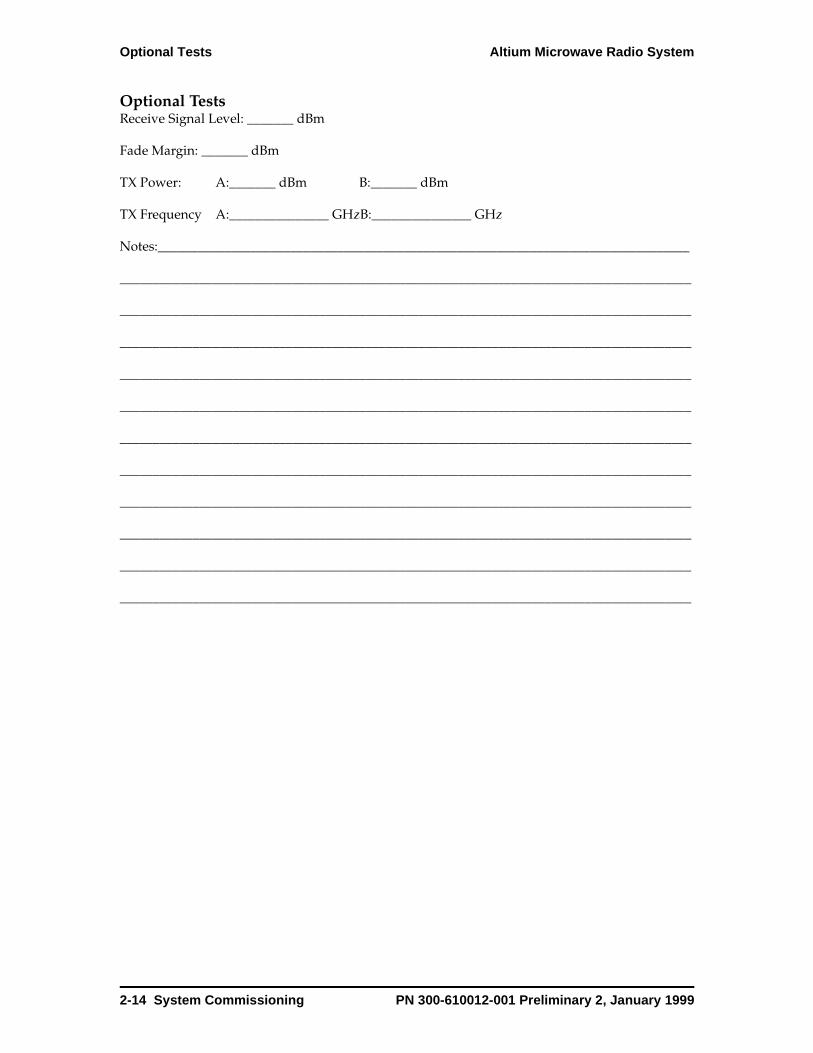
Optional Tests Altium Microwave Radio System
Optional TestsReceive Signal Level: _______ dBm
Fade Margin: _______ dBm
TX Power: A:_______ dBm B:_______ dBm
TX Frequency A:_______________ GHzB:_______________ GHz
Notes:________________________________________________________________________________
______________________________________________________________________________________
______________________________________________________________________________________
______________________________________________________________________________________
______________________________________________________________________________________
______________________________________________________________________________________
______________________________________________________________________________________
______________________________________________________________________________________
______________________________________________________________________________________
______________________________________________________________________________________
______________________________________________________________________________________
______________________________________________________________________________________
2-14 System Commissioning PN 300-610012-001 Preliminary 2, January 1999
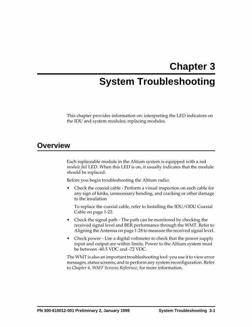
Chapter 3
System Troubleshootin g
This chapter provides information on: interpreting the LED indicators on the IDU and system modules; replacing modules.
Overview
Each replaceable module in the Altium system is equipped with a red module fail LED. When this LED is on, it usually indicates that the module should be replaced.
Before you begin troubleshooting the Altium radio:
• Check the coaxial cable - Perform a visual inspection on each cable for any sign of kinks, unnecessary bending, and cracking or other damage to the insulation
To replace the coaxial cable, refer to Installing the IDU/ODU Coaxial Cable on page 1-22.
• Check the signal path - The path can be monitored by checking the received signal level and BER performance through the WMT. Refer to Aligning the Antenna on page 1-28 to measure the received signal level.
• Check power - Use a digital voltmeter to check that the power supply input and output are within limits. Power to the Altium system must be between -40.5 VDC and -72 VDC.
The WMT is also an important troubleshooting tool: you use it to view error messages, status screens, and to perform any system reconfiguration. Refer to Chapter 4, WMT Screens Reference, for more information.
PN 300-610012-001 Preliminary 2, January 1999 System Troubleshooting 3-1
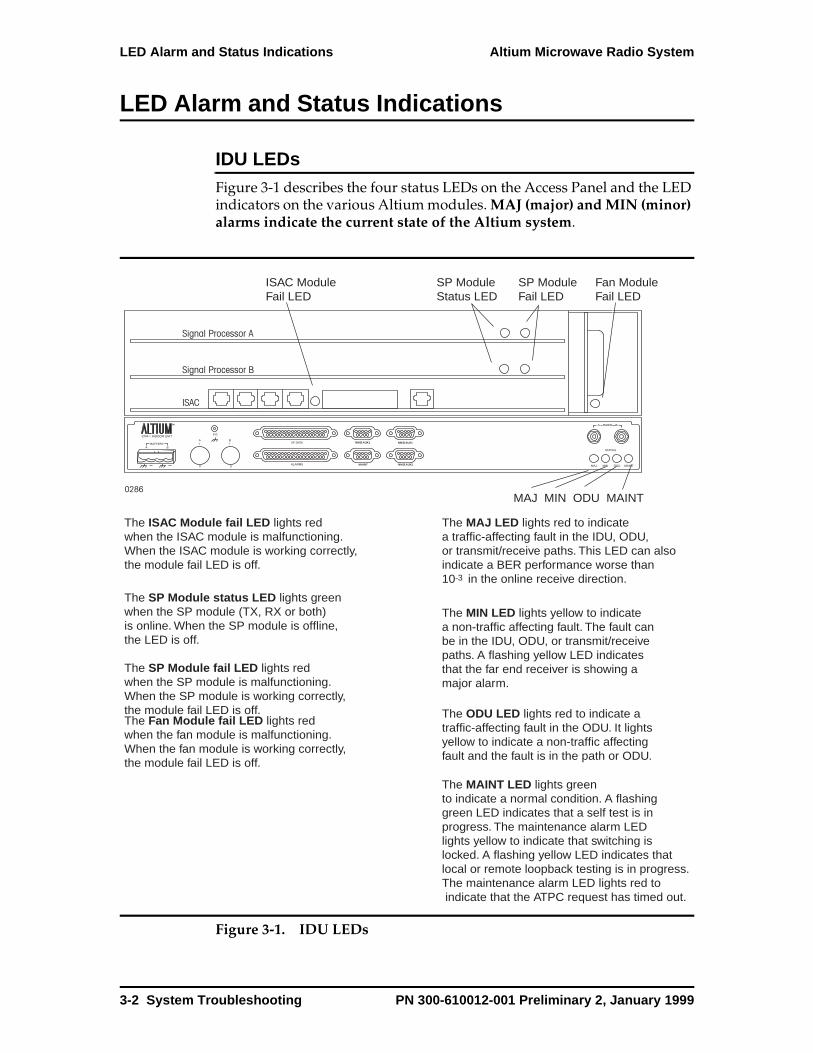
LED Alarm and Status Indications Altium Microwave Radio System
LED Alarm and Status Indications
IDU LEDsFigure 3-1 describes the four status LEDs on the Access Panel and the LED indicators on the various Altium modules. MAJ (major) and MIN (minor) alarms indicate the current state of the Altium system.
Figure 3-1. IDU LEDs
0286
Signal Processor A
Signal Processor B
ISAC
B
ANMS/AUX1 NMS/AUX1
NMS/AUX2MAINT
ESD
The ODU LED lights red to indicate a traffic-affecting fault in the ODU. It lights yellow to indicate a non-traffic affecting fault and the fault is in the path or ODU.
The MIN LED lights yellow to indicate a non-traffic affecting fault. The fault can be in the IDU, ODU, or transmit/receive paths. A flashing yellow LED indicates that the far end receiver is showing a major alarm.
The MAJ LED lights red to indicate a traffic-affecting fault in the IDU, ODU,or transmit/receive paths. This LED can also indicate a BER performance worse than 10 in the online receive direction.-3
The MAINT LED lights green to indicate a normal condition. A flashing green LED indicates that a self test is in progress. The maintenance alarm LED lights yellow to indicate that switching is locked. A flashing yellow LED indicates that local or remote loopback testing is in progress.The maintenance alarm LED lights red to indicate that the ATPC request has timed out.
The SP Module status LED lights green when the SP module (TX, RX or both)is online. When the SP module is offline, the LED is off.
The SP Module fail LED lights red when the SP module is malfunctioning. When the SP module is working correctly, the module fail LED is off.The Fan Module fail LED lights red when the fan module is malfunctioning. When the fan module is working correctly, the module fail LED is off.
The ISAC Module fail LED lights redwhen the ISAC module is malfunctioning. When the ISAC module is working correctly, the module fail LED is off.
ISAC Module Fail LED
SP ModuleFail LED
SP ModuleStatus LED
Fan ModuleFail LED
MAJ MIN ODU MAINT
3-2 System Troubleshooting PN 300-610012-001 Preliminary 2, January 1999

Altium Microwave Radio System LED Alarm and Status Indications
ODU LEDsFigure 3-2 describes the status LEDs on the OSAC module and the LED indicators on the RF plug-in modules.
Figure 3-2. ODU LEDs
B-side Status LED
The Module Fail LED is red.When the LED is on, the RFplug-in is malfunctioning. When the LED is off, the RFplug-in is working correctly.
The Status LED is green. When the LED is on, the RF plug-in is on-line. Whenthe LED is off, the RF plug-in is off-line.
The OSAC Module Fail LED is red. When it is on, the OSAC is malfunctioning. When it is off, the OSAC is working correctly.If this LED is flashing, the OSAC is being initializedor there is an RFTX switchfault.
B-side Module Fail LED
OSAC Module Fail LED
A-side Module Fail LED
A-side Status LED
PN 300-610012-001 Preliminary 2, January 1999 System Troubleshooting 3-3

LED Troubleshooting Altium Microwave Radio System
LED Troubleshooting
Table 3-1. LED Troubleshooting
SP module fail LED Red
WMT Events SP A/B transmit summary alarm
Possible Failure Optical input, Mux PLL, 310 IF
Recommended Action Replace SP module.
WMT Events SP A/B receive summary alarm
Possible Failure Demux PLL, Demod PLL
Recommended Action Replace SP module.
ISAC module fail LED Red
WMT Events ISAC summary alarm
Possible Failure Watchdog alarm, Serial device alarm, Ethernet hub alarm
Recommended Action Replace ISAC module.
Fan module fail LED Red
WMT Events Fan summary alarm
Possible Failure Front fan, rear fan, fan IDPROM
Recommended Action Replace fan module.
RF Plug-in LED Red
WMT Events RF Plug-in No Response
Possible Failure TX synth, power amp, 310 ALC, ATPC
Recommended Action Replace RF Plug-in module.
WMT Events RF plug-in receive summary alarm
Possible Failure RX synth
Recommended Action Replace RF Plug-in module.
OSAC LED Red
WMT Events OSAC summary alarm
Possible Failure OSAC ID PROM
Recommended Action Replace OSAC module.
OSAC LED Flashing Red
WMT Events RF TX A/B switch alarm
Possible Failure RF Distribution module, Watchdog alarm
Recommended Action Replace RF Distribution module.
3-4 System Troubleshooting PN 300-610012-001 Preliminary 2, January 1999

Altium Microwave Radio System Indirectly Detected and Undetected Faults
Indirectly Detected and Undetected Faults
There can be faults that go undetected or are expressed by a module that is not itself the cause of the fault. This requires a process of elimination based on experience, especially since it is usually not practical to bring special test equipment to the site.
As an example, if an RF Plug-in has a noisy receive local oscillator, this problem shows up as a high BER condition and possibly as a receive SP alarm LED. The first approach would be to replace the SP card. When this didn’t solve the problem the RF Plug-in would be the next module to replace. After replacing the RF Plug-in module the problem would be resolved. A similar situation could arise from a path or remote transmitter problem, particularly in a non-protected system with only one receiver.
The proper isolation of these types of problems comes from careful observation of present indications (active LEDs and WMT active fault log) and historical data (WMT fault history log). RSSI readings can also help determine whether it is a possible path condition that is causing the fault. If the Altium system is protected, various transmit/receive on-line combinations can be put into service to isolate the faulty unit. DMC customer service can also provide assistance. See Customer Service on page xiii.
Returning Equipment to DMC
When you replace a module that must be returned to DMC for repairs, you must:
1. Obtain a Return Material Authorization number from
2. Include the part number, serial number, and information regarding the environment the module operated in.
PN 300-610012-001 Preliminary 2, January 1999 System Troubleshooting 3-5
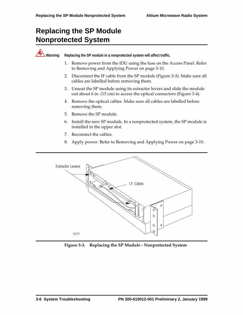
Replacing the SP Module Nonprotected System Altium Microwave Radio System
Replacing the SP Module Nonprotected System
Warning: Replacing the SP module in a nonprotected system will affect traffic.
1. Remove power from the IDU using the fuse on the Access Panel. Refer to Removing and Applying Power on page 3-10.
2. Disconnect the IF cable from the SP module (Figure 3-3). Make sure all cables are labelled before removing them.
3. Unseat the SP module using its extractor levers and slide the module out about 6 in. (15 cm) to access the optical connectors (Figure 3-4).
4. Remove the optical cables. Make sure all cables are labelled before removing them.
5. Remove the SP module.
6. Install the new SP module. In a nonprotected system, the SP module is installed in the upper slot.
7. Reconnect the cables.
8. Apply power. Refer to Removing and Applying Power on page 3-10.
Figure 3-3. Replacing the SP Module - Nonprotected System
0272
Extractor Levers
I.F. Cable
3-6 System Troubleshooting PN 300-610012-001 Preliminary 2, January 1999
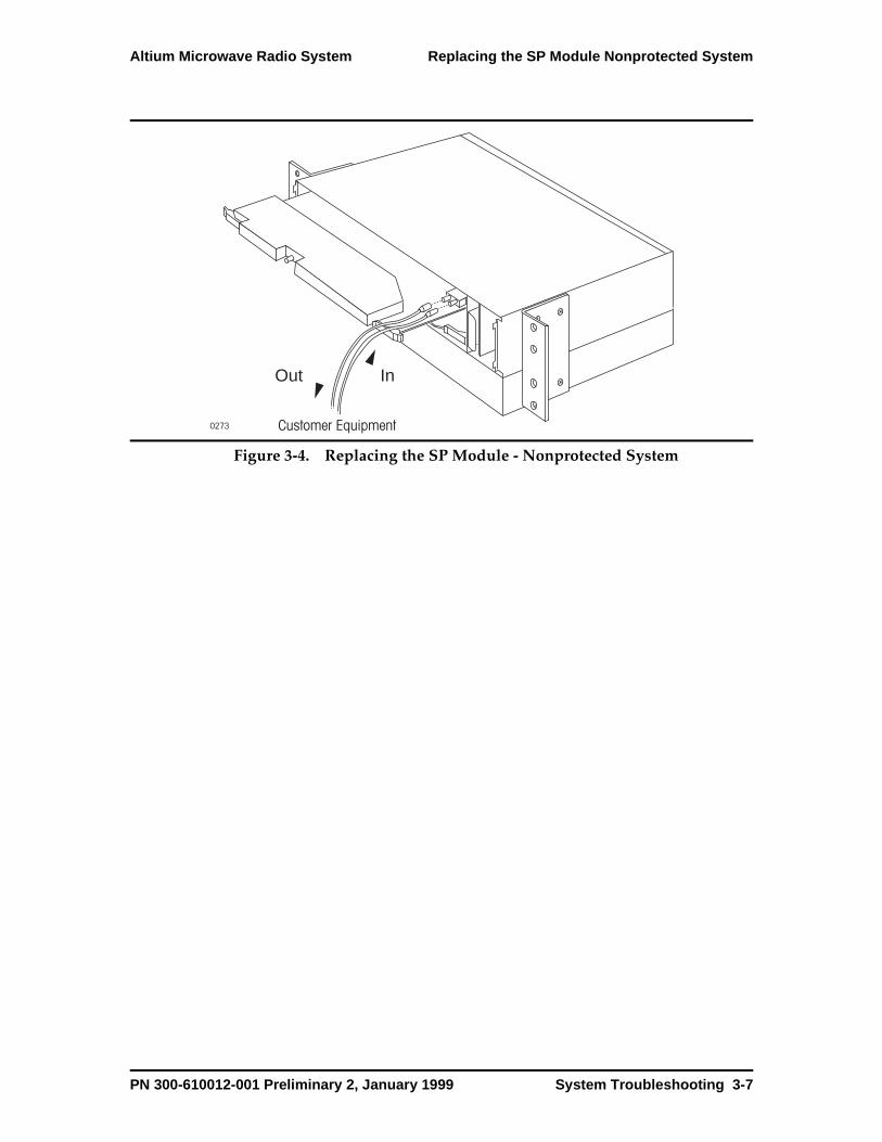
Altium Microwave Radio System Replacing the SP Module Nonprotected System
Figure 3-4. Replacing the SP Module - Nonprotected System
0273 Customer Equipment
InOut
PN 300-610012-001 Preliminary 2, January 1999 System Troubleshooting 3-7
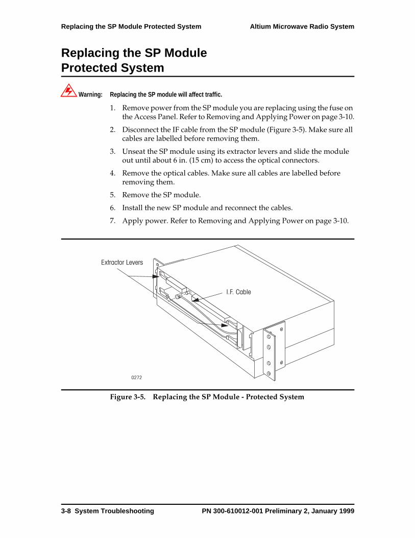
Replacing the SP Module Protected System Altium Microwave Radio System
Replacing the SP Module Protected System
Warning: Replacing the SP module will affect traffic.
1. Remove power from the SP module you are replacing using the fuse on the Access Panel. Refer to Removing and Applying Power on page 3-10.
2. Disconnect the IF cable from the SP module (Figure 3-5). Make sure all cables are labelled before removing them.
3. Unseat the SP module using its extractor levers and slide the module out until about 6 in. (15 cm) to access the optical connectors.
4. Remove the optical cables. Make sure all cables are labelled before removing them.
5. Remove the SP module.
6. Install the new SP module and reconnect the cables.
7. Apply power. Refer to Removing and Applying Power on page 3-10.
Figure 3-5. Replacing the SP Module - Protected System
0272
Extractor Levers
I.F. Cable
3-8 System Troubleshooting PN 300-610012-001 Preliminary 2, January 1999

Altium Microwave Radio System Replacing the SP Module Protected System
Figure 3-6. Replacing the SP Module - Protected System
0273 Customer Equipment
InOut
PN 300-610012-001 Preliminary 2, January 1999 System Troubleshooting 3-9
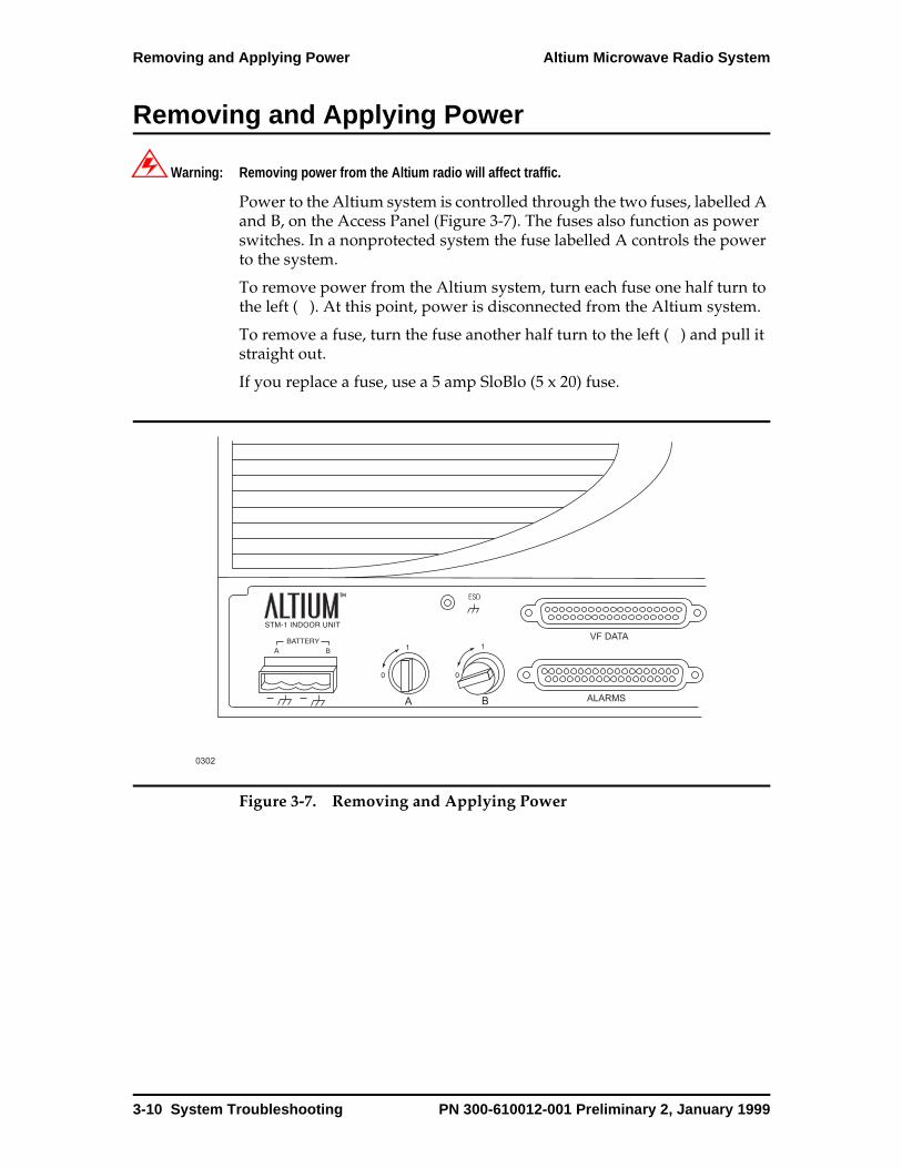
Removing and Applying Power Altium Microwave Radio System
Removing and Applying Power
Warning: Removing power from the Altium radio will affect traffic.
Power to the Altium system is controlled through the two fuses, labelled A and B, on the Access Panel (Figure 3-7). The fuses also function as power switches. In a nonprotected system the fuse labelled A controls the power to the system.
To remove power from the Altium system, turn each fuse one half turn to the left ( ). At this point, power is disconnected from the Altium system.
To remove a fuse, turn the fuse another half turn to the left ( ) and pull it straight out.
If you replace a fuse, use a 5 amp SloBlo (5 x 20) fuse.
Figure 3-7. Removing and Applying Power
B
A B
0302
ESD
VF DATA
ALARMS
3-10 System Troubleshooting PN 300-610012-001 Preliminary 2, January 1999
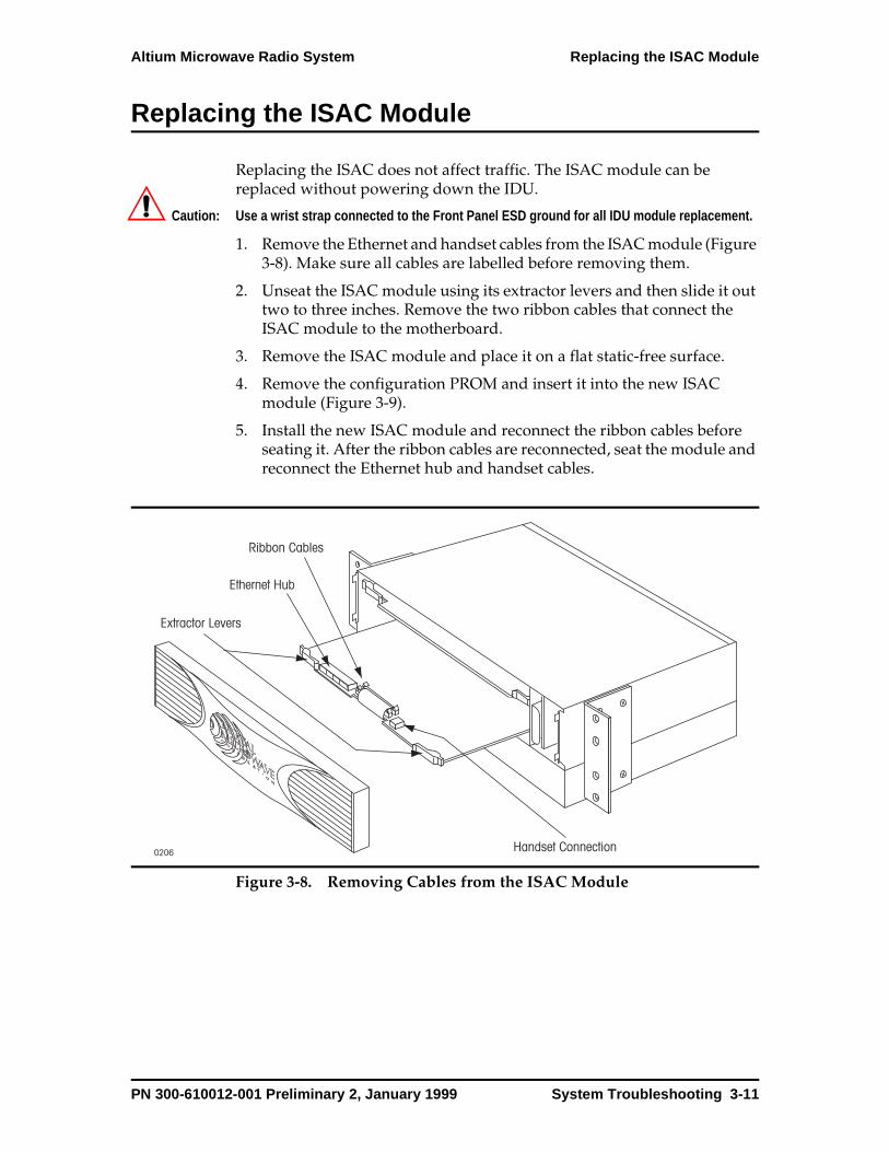
Altium Microwave Radio System Replacing the ISAC Module
Replacing the ISAC Module
Replacing the ISAC does not affect traffic. The ISAC module can be replaced without powering down the IDU.
Caution: Use a wrist strap connected to the Front Panel ESD ground for all IDU module replacement.
1. Remove the Ethernet and handset cables from the ISAC module (Figure 3-8). Make sure all cables are labelled before removing them.
2. Unseat the ISAC module using its extractor levers and then slide it out two to three inches. Remove the two ribbon cables that connect the ISAC module to the motherboard.
3. Remove the ISAC module and place it on a flat static-free surface.
4. Remove the configuration PROM and insert it into the new ISAC module (Figure 3-9).
5. Install the new ISAC module and reconnect the ribbon cables before seating it. After the ribbon cables are reconnected, seat the module and reconnect the Ethernet hub and handset cables.
Figure 3-8. Removing Cables from the ISAC Module
0206
Extractor Levers
Ethernet Hub
Handset Connection
Ribbon Cables
PN 300-610012-001 Preliminary 2, January 1999 System Troubleshooting 3-11

Replacing the ISAC Module Altium Microwave Radio System
Figure 3-9. ISAC Configuration PROM
0207
Configuration PROM
3-12 System Troubleshooting PN 300-610012-001 Preliminary 2, January 1999

Altium Microwave Radio System Replacing the Fan Module
Replacing the Fan Module
The fan module can be replaced without affecting traffic.
Warning: Do not operate the Altium system over 15 minutes without the fan module.
1. Unplug the fan module (Figure 3-10).
2. Install the new fan module.
Figure 3-10. Replacing the Fan Module
0198 FanPull Here
PN 300-610012-001 Preliminary 2, January 1999 System Troubleshooting 3-13
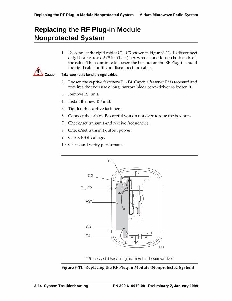
Replacing the RF Plug-in Module Nonprotected System Altium Microwave Radio System
Replacing the RF Plug-in Module Nonprotected System
1. Disconnect the rigid cables C1 - C3 shown in Figure 3-11. To disconnect a rigid cable, use a 3/8 in. (1 cm) hex wrench and loosen both ends of the cable. Then continue to loosen the hex nut on the RF Plug-in end of the rigid cable until you disconnect the cable.
Caution: Take care not to bend the rigid cables.
2. Loosen the captive fasteners F1 - F4. Captive fastener F3 is recessed and requires that you use a long, narrow-blade screwdriver to loosen it.
3. Remove RF unit.
4. Install the new RF unit.
5. Tighten the captive fasteners.
6. Connect the cables. Be careful you do not over-torque the hex nuts.
7. Check/set transmit and receive frequencies.
8. Check/set transmit output power.
9. Check RSSI voltage.
10. Check and verify performance.
Figure 3-11. Replacing the RF Plug-in Module (Nonprotected System)
0306
C1
C2
C3
F1, F2
F3*
F4
Recessed. Use a long, narrow-blade screwdriver.*
3-14 System Troubleshooting PN 300-610012-001 Preliminary 2, January 1999
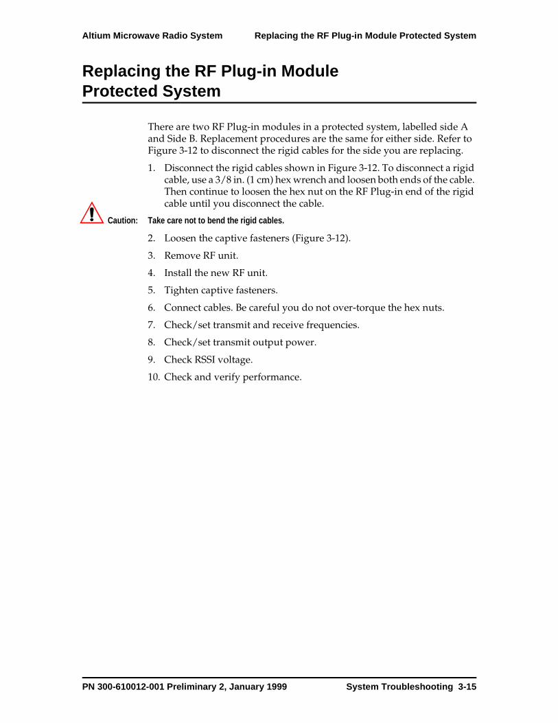
Altium Microwave Radio System Replacing the RF Plug-in Module Protected System
Replacing the RF Plug-in Module Protected System
There are two RF Plug-in modules in a protected system, labelled side A and Side B. Replacement procedures are the same for either side. Refer to Figure 3-12 to disconnect the rigid cables for the side you are replacing.
1. Disconnect the rigid cables shown in Figure 3-12. To disconnect a rigid cable, use a 3/8 in. (1 cm) hex wrench and loosen both ends of the cable. Then continue to loosen the hex nut on the RF Plug-in end of the rigid cable until you disconnect the cable.
Caution: Take care not to bend the rigid cables.
2. Loosen the captive fasteners (Figure 3-12).
3. Remove RF unit.
4. Install the new RF unit.
5. Tighten captive fasteners.
6. Connect cables. Be careful you do not over-torque the hex nuts.
7. Check/set transmit and receive frequencies.
8. Check/set transmit output power.
9. Check RSSI voltage.
10. Check and verify performance.
PN 300-610012-001 Preliminary 2, January 1999 System Troubleshooting 3-15

Replacing the RF Plug-in Module Protected System Altium Microwave Radio System
Figure 3-12. Replacing the RF Plug-in Module (Protected System)
0288
C1
C2
C3
C4
C5
C6
F5, F6
F7*
F8
F1, F2
F3*
F4
*Recessed. Use a long, narrow-blade screwdriver.
3-16 System Troubleshooting PN 300-610012-001 Preliminary 2, January 1999
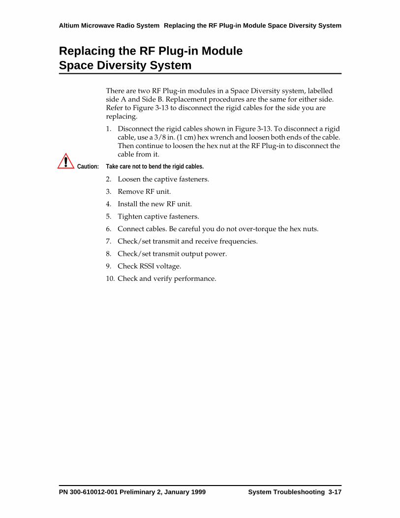
Altium Microwave Radio System Replacing the RF Plug-in Module Space Diversity System
Replacing the RF Plug-in Module Space Diversity System
There are two RF Plug-in modules in a Space Diversity system, labelled side A and Side B. Replacement procedures are the same for either side. Refer to Figure 3-13 to disconnect the rigid cables for the side you are replacing.
1. Disconnect the rigid cables shown in Figure 3-13. To disconnect a rigid cable, use a 3/8 in. (1 cm) hex wrench and loosen both ends of the cable. Then continue to loosen the hex nut at the RF Plug-in to disconnect the cable from it.
Caution: Take care not to bend the rigid cables.
2. Loosen the captive fasteners.
3. Remove RF unit.
4. Install the new RF unit.
5. Tighten captive fasteners.
6. Connect cables. Be careful you do not over-torque the hex nuts.
7. Check/set transmit and receive frequencies.
8. Check/set transmit output power.
9. Check RSSI voltage.
10. Check and verify performance.
PN 300-610012-001 Preliminary 2, January 1999 System Troubleshooting 3-17
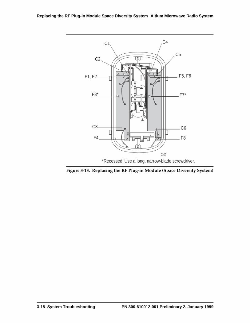
Replacing the RF Plug-in Module Space Diversity System Altium Microwave Radio System
Figure 3-13. Replacing the RF Plug-in Module (Space Diversity System)
0307
C1
C2
C3
C4
C5
C6
F1, F2
F3*
F4
F5, F6
F7*
F8
*Recessed. Use a long, narrow-blade screwdriver.
3-18 System Troubleshooting PN 300-610012-001 Preliminary 2, January 1999
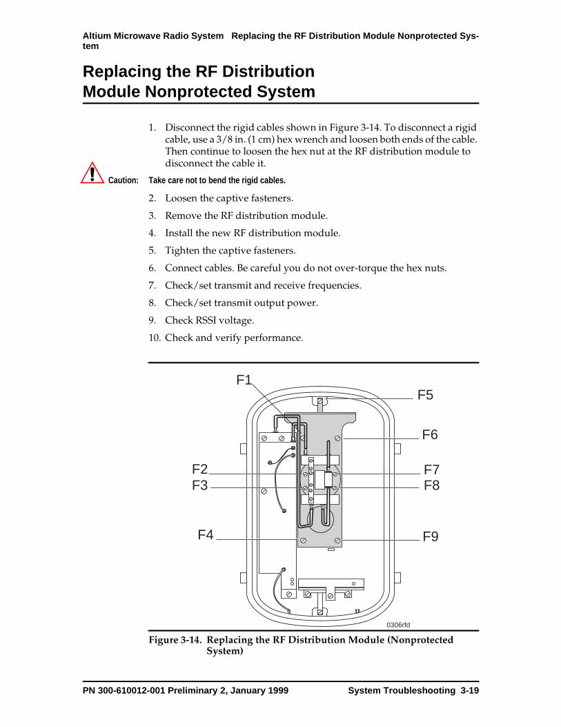
Altium Microwave Radio System Replacing the RF Distribution Module Nonprotected Sys-tem
Replacing the RF Distribution Module Nonprotected System
1. Disconnect the rigid cables shown in Figure 3-14. To disconnect a rigid cable, use a 3/8 in. (1 cm) hex wrench and loosen both ends of the cable. Then continue to loosen the hex nut at the RF distribution module to disconnect the cable it.
Caution: Take care not to bend the rigid cables.
2. Loosen the captive fasteners.
3. Remove the RF distribution module.
4. Install the new RF distribution module.
5. Tighten the captive fasteners.
6. Connect cables. Be careful you do not over-torque the hex nuts.
7. Check/set transmit and receive frequencies.
8. Check/set transmit output power.
9. Check RSSI voltage.
10. Check and verify performance.
Figure 3-14. Replacing the RF Distribution Module (Nonprotected System)
0306rfd
F1
F2F3
F4
F5
F6
F7F8
F9
PN 300-610012-001 Preliminary 2, January 1999 System Troubleshooting 3-19
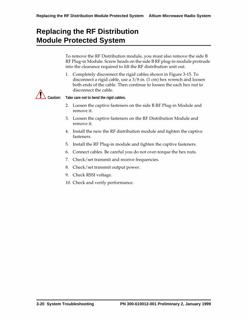
Replacing the RF Distribution Module Protected System Altium Microwave Radio System
Replacing the RF Distribution Module Protected System
To remove the RF Distribution module, you must also remove the side B RF Plug-in Module. Screw heads on the side B RF plug-in module protrude into the clearance required to lift the RF distribution unit out.
1. Completely disconnect the rigid cables shown in Figure 3-15. To disconnect a rigid cable, use a 3/8 in. (1 cm) hex wrench and loosen both ends of the cable. Then continue to loosen the each hex nut to disconnect the cable.
Caution: Take care not to bend the rigid cables.
2. Loosen the captive fasteners on the side B RF Plug-in Module and remove it.
3. Loosen the captive fasteners on the RF Distribution Module and remove it.
4. Install the new the RF distribution module and tighten the captive fasteners.
5. Install the RF Plug-in module and tighten the captive fasteners.
6. Connect cables. Be careful you do not over-torque the hex nuts.
7. Check/set transmit and receive frequencies.
8. Check/set transmit output power.
9. Check RSSI voltage.
10. Check and verify performance.
3-20 System Troubleshooting PN 300-610012-001 Preliminary 2, January 1999
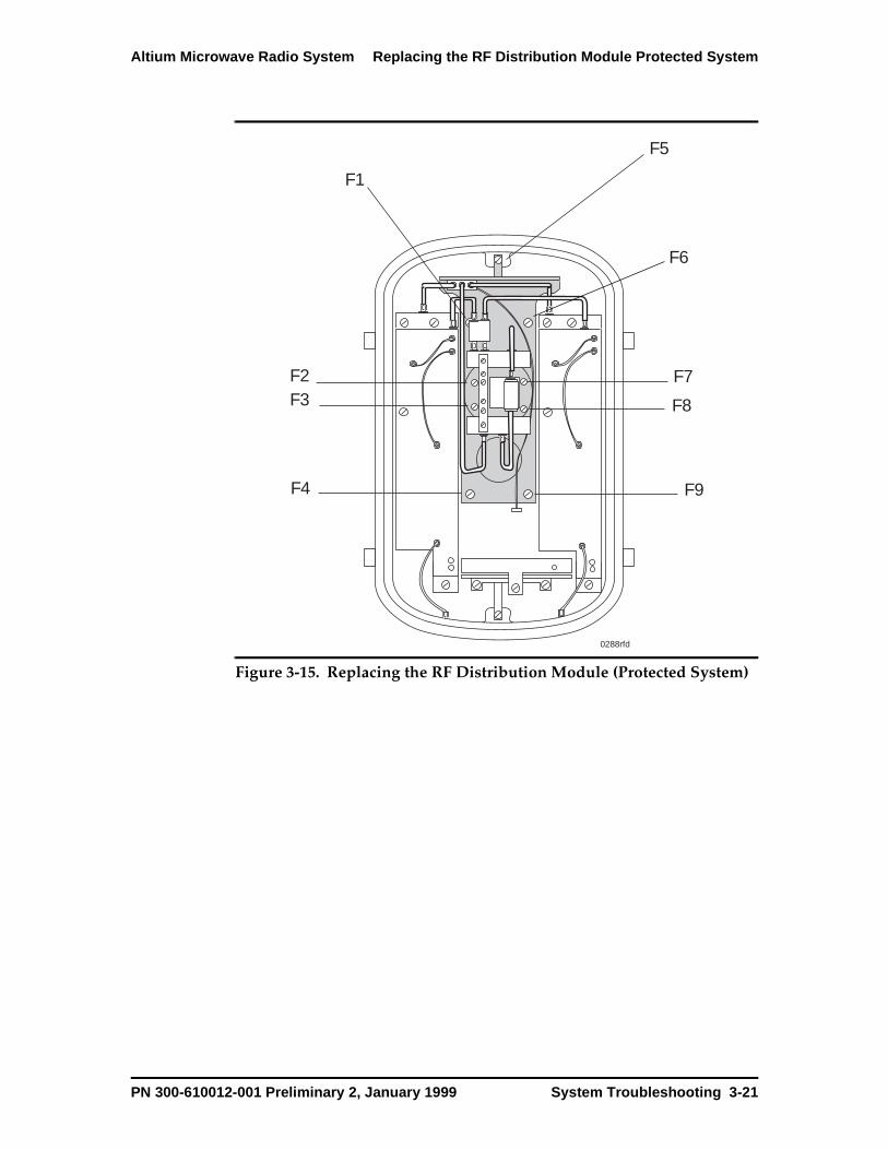
Altium Microwave Radio System Replacing the RF Distribution Module Protected System
Figure 3-15. Replacing the RF Distribution Module (Protected System)
0288rfd
F1
F2F3
F4
F5
F6
F7
F8
F9
PN 300-610012-001 Preliminary 2, January 1999 System Troubleshooting 3-21
Replacing the RF Distribution Module Space Diversity SystemAltium Microwave Radio Sys-tem
Replacing the RF Distribution Module Space Diversity System
To remove the RF Distribution module, it is recommended that you first remove each RF Plug-in module (side A in a nonprotected ODU and sides A and B in a protected ODU).
1. Completely disconnect the rigid cables shown in Figure 3-14. To disconnect a rigid cable, use a 3/8 in. (1 cm) hex wrench and loosen both ends of the cable. Then continue to loosen the each hex nut to disconnect the cable.
Caution: Take care not to bend the rigid cables.
2. Loosen the captive fasteners on the side B RF Plug-in Module and remove it.
3. Loosen the captive fasteners on the RF Distribution Module and remove it.
4. Install the new the RF distribution module and tighten the captive fasteners.
5. Install the RF Plug-in module and tighten the captive fasteners.
6. Connect cables. Be careful you do not over-torque the hex nuts.
7. Check/set transmit and receive frequencies.
8. Check/set transmit output power.
9. Check RSSI voltage.
10. Check and verify performance.
3-22 System Troubleshooting PN 300-610012-001 Preliminary 2, January 1999
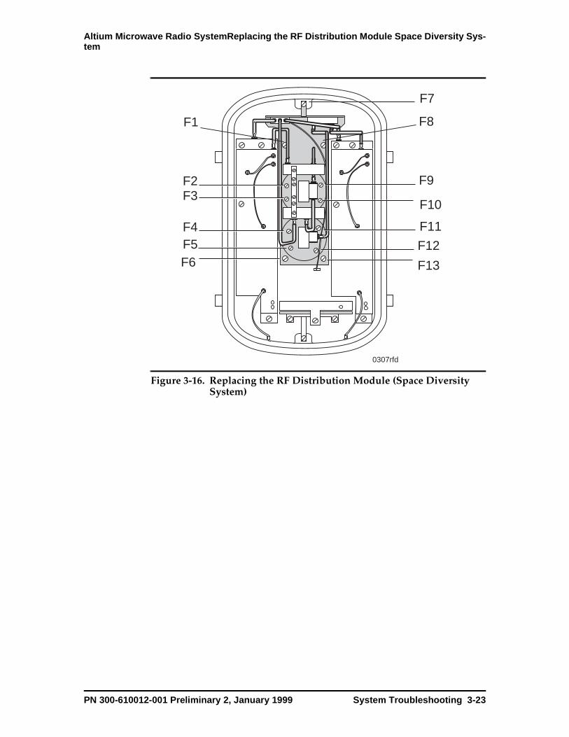
Altium Microwave Radio SystemReplacing the RF Distribution Module Space Diversity Sys-tem
Figure 3-16. Replacing the RF Distribution Module (Space Diversity System)
0307rfd
F1
F2F3
F4F5F6
F7
F8
F9
F10
F11
F12
F13
PN 300-610012-001 Preliminary 2, January 1999 System Troubleshooting 3-23

Replacing the OSAC Module Altium Microwave Radio System
Replacing the OSAC Module
The procedure for replacing the OSAC module is the same for the nonprotected, protected, and protected space diversity system.
Note: Replacing the OSAC module does not affect traffic.
1. Loosen the captive fastener (A in Figure 3-17).
2. Pull the OSAC straight out.
3. Slide the new OSAC into the guides and push it firmly to seat it into the connector.
4. Tighten the captive fastener.
Figure 3-17. Replacing the OSAC Module
0288osac
F1
3-24 System Troubleshooting PN 300-610012-001 Preliminary 2, January 1999
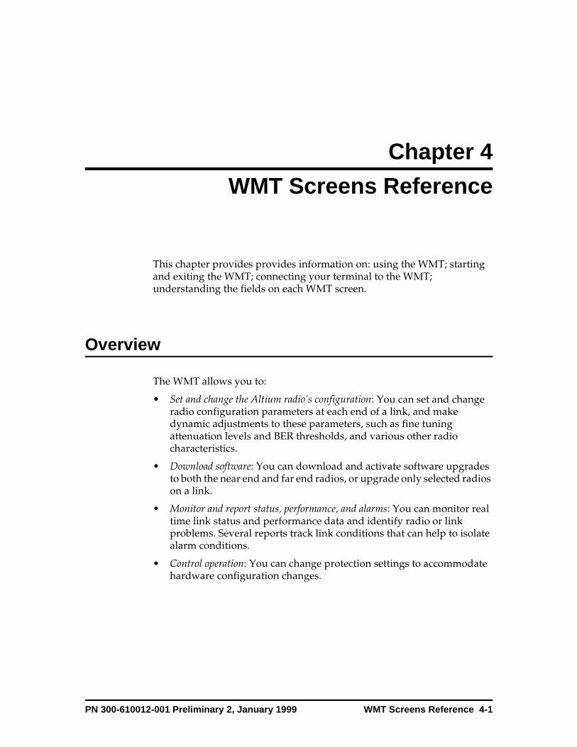
Chapter 4
WMT Screens Reference
This chapter provides provides information on: using the WMT; starting and exiting the WMT; connecting your terminal to the WMT; understanding the fields on each WMT screen.
Overview
The WMT allows you to:
• Set and change the Altium radio’s configuration: You can set and change radio configuration parameters at each end of a link, and make dynamic adjustments to these parameters, such as fine tuning attenuation levels and BER thresholds, and various other radio characteristics.
• Download software: You can download and activate software upgrades to both the near end and far end radios, or upgrade only selected radios on a link.
• Monitor and report status, performance, and alarms: You can monitor real time link status and performance data and identify radio or link problems. Several reports track link conditions that can help to isolate alarm conditions.
• Control operation: You can change protection settings to accommodate hardware configuration changes.
PN 300-610012-001 Preliminary 2, January 1999 WMT Screens Reference 4-1
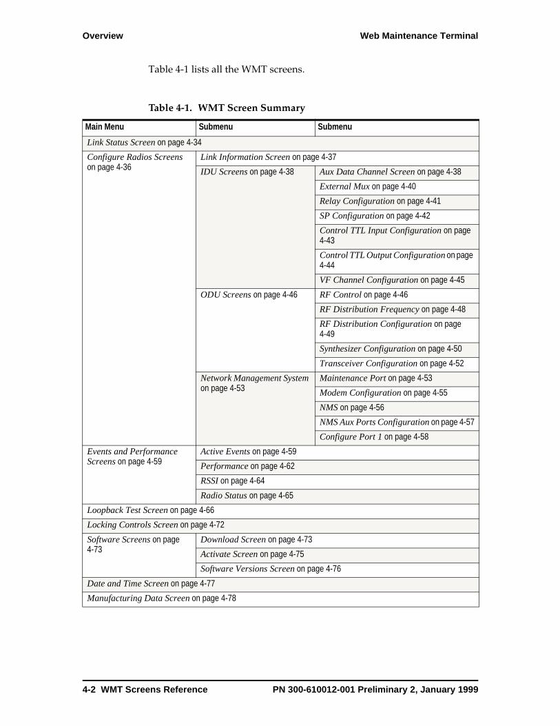
Overview Web Maintenance Terminal
Table 4-1 lists all the WMT screens.
Table 4-1. WMT Screen Summary
Main Menu Submenu Submenu
Link Status Screen on page 4-34
Configure Radios Screens on page 4-36
Link Information Screen on page 4-37
IDU Screens on page 4-38 Aux Data Channel Screen on page 4-38
External Mux on page 4-40
Relay Configuration on page 4-41
SP Configuration on page 4-42
Control TTL Input Configuration on page 4-43
Control TTL Output Configuration on page 4-44
VF Channel Configuration on page 4-45
ODU Screens on page 4-46 RF Control on page 4-46
RF Distribution Frequency on page 4-48
RF Distribution Configuration on page 4-49
Synthesizer Configuration on page 4-50
Transceiver Configuration on page 4-52
Network Management System on page 4-53
Maintenance Port on page 4-53
Modem Configuration on page 4-55
NMS on page 4-56
NMS Aux Ports Configuration on page 4-57
Configure Port 1 on page 4-58
Events and Performance Screens on page 4-59
Active Events on page 4-59
Performance on page 4-62
RSSI on page 4-64
Radio Status on page 4-65
Loopback Test Screen on page 4-66
Locking Controls Screen on page 4-72
Software Screens on page 4-73
Download Screen on page 4-73
Activate Screen on page 4-75
Software Versions Screen on page 4-76
Date and Time Screen on page 4-77
Manufacturing Data Screen on page 4-78
4-2 WMT Screens Reference PN 300-610012-001 Preliminary 2, January 1999
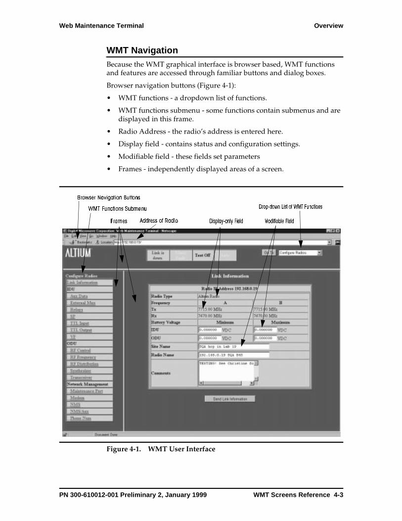
Web Maintenance Terminal Overview
WMT NavigationBecause the WMT graphical interface is browser based, WMT functions and features are accessed through familiar buttons and dialog boxes.
Browser navigation buttons (Figure 4-1):
• WMT functions - a dropdown list of functions.
• WMT functions submenu - some functions contain submenus and are displayed in this frame.
• Radio Address - the radio’s address is entered here.
• Display field - contains status and configuration settings.
• Modifiable field - these fields set parameters
• Frames - independently displayed areas of a screen.
Figure 4-1. WMT User Interface
Browser Navigation Buttons
Address of Radio
Drop-down List of WMT FunctionsWMT Functions Submenu
Display-only Field Modifiable FieldFrames
PN 300-610012-001 Preliminary 2, January 1999 WMT Screens Reference 4-3

Overview Web Maintenance Terminal
A WMT session uses frames to display information. The top frame, which contains the WMT menu, is a permanent frame. It displays for all WMT screens.
The starting screen for a WMT session is the Link Status screen (Figure 4-2). To go to another WMT screen, click in the menu list to display the WMT menu. Click a menu item to display that WMT screen. For example, click the menu list, click Configure Radios (Figure 4-3), and WMT displays the Configure Radios screen (Figure 4-4).
Figure 4-2. WMT Start-up Screen
4-4 WMT Screens Reference PN 300-610012-001 Preliminary 2, January 1999
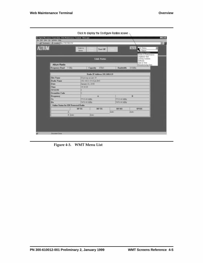
Web Maintenance Terminal Overview
Figure 4-3. WMT Menu List
Click to display the Configure Radios screen
PN 300-610012-001 Preliminary 2, January 1999 WMT Screens Reference 4-5
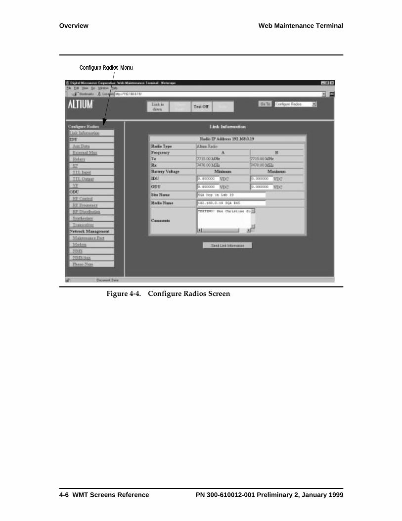
Overview Web Maintenance Terminal
Figure 4-4. Configure Radios Screen
Configure Radios Menu
4-6 WMT Screens Reference PN 300-610012-001 Preliminary 2, January 1999
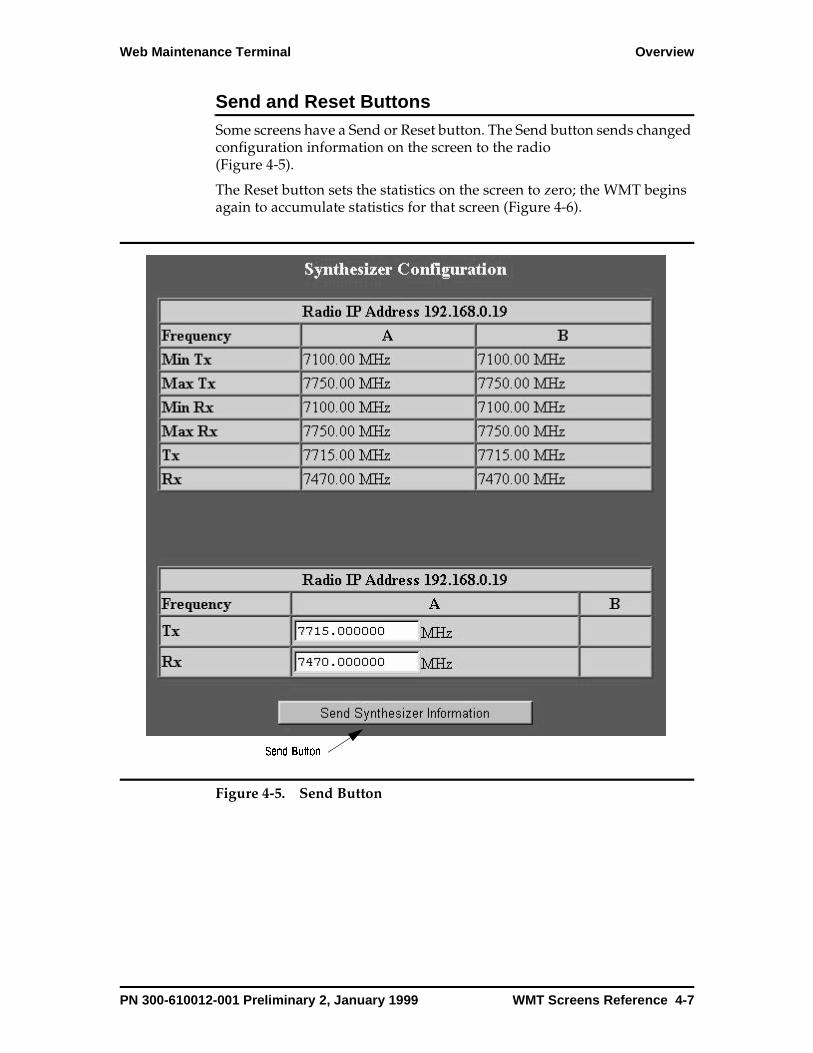
Web Maintenance Terminal Overview
Send and Reset ButtonsSome screens have a Send or Reset button. The Send button sends changed configuration information on the screen to the radio (Figure 4-5).
The Reset button sets the statistics on the screen to zero; the WMT begins again to accumulate statistics for that screen (Figure 4-6).
Figure 4-5. Send Button
Send Button
PN 300-610012-001 Preliminary 2, January 1999 WMT Screens Reference 4-7
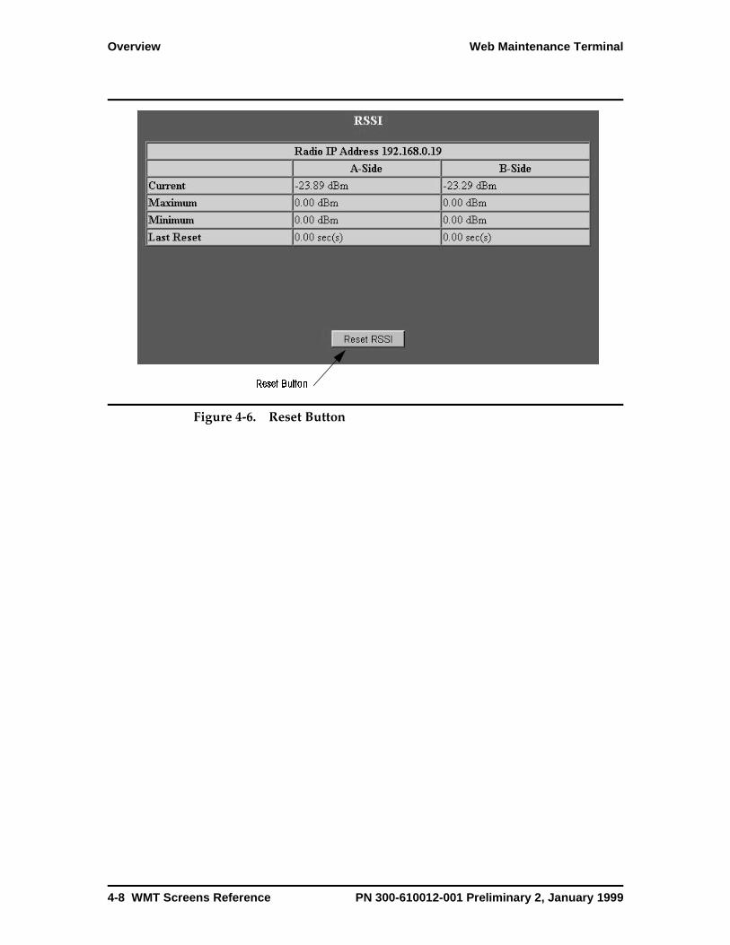
Overview Web Maintenance Terminal
Figure 4-6. Reset Button
Reset Button
4-8 WMT Screens Reference PN 300-610012-001 Preliminary 2, January 1999

Web Maintenance Terminal Connecting the WMT to the Altium Radio
Connecting the WMT to the Altium Radio
There are two ways to connect directly to the WMT:
• Connecting to the Ethernet hub. You use an Ethernet 10Base-T cable to connect your terminal, through its network interface card, to the Ethernet hub. See Making an Ethernet Connection on page 4-9.
• Connecting to the MAINT connector. You use a serial cable to connect your terminal (RS-232, V.28 signal levels), through a COMM port, to the MAINT connector on the Access Panel. See Connecting through the MAINT Connector on page 4-14.
A remote connection is described here as using the local radio as a gateway to connect to the far end. See Connecting to the Far End from the Local Radio on page 4-29.
Figure 4-7. Connecting the WMT
Making an Ethernet ConnectionTo make an Ethernet connection from your terminal to the WMT, your terminal must be equipped with an Ethernet interface and you must use a length of 10Base-T cable. For more information on the Ethernet hub, see Ethernet Hub on page 1-30.
This procedure describes how to determine the IP address and subnet mask for your terminal.
0229
B
A
ESD
VF DATA
ALARMS
NMS/AUX 1
MAINT
NMS/AUX 1
NMS/AUX 2
STATUS
MAJ MIN ODU MAINT
MAINTConnector
EthernetHub
SerialPort
EthernetCard
PN 300-610012-001 Preliminary 2, January 1999 WMT Screens Reference 4-9
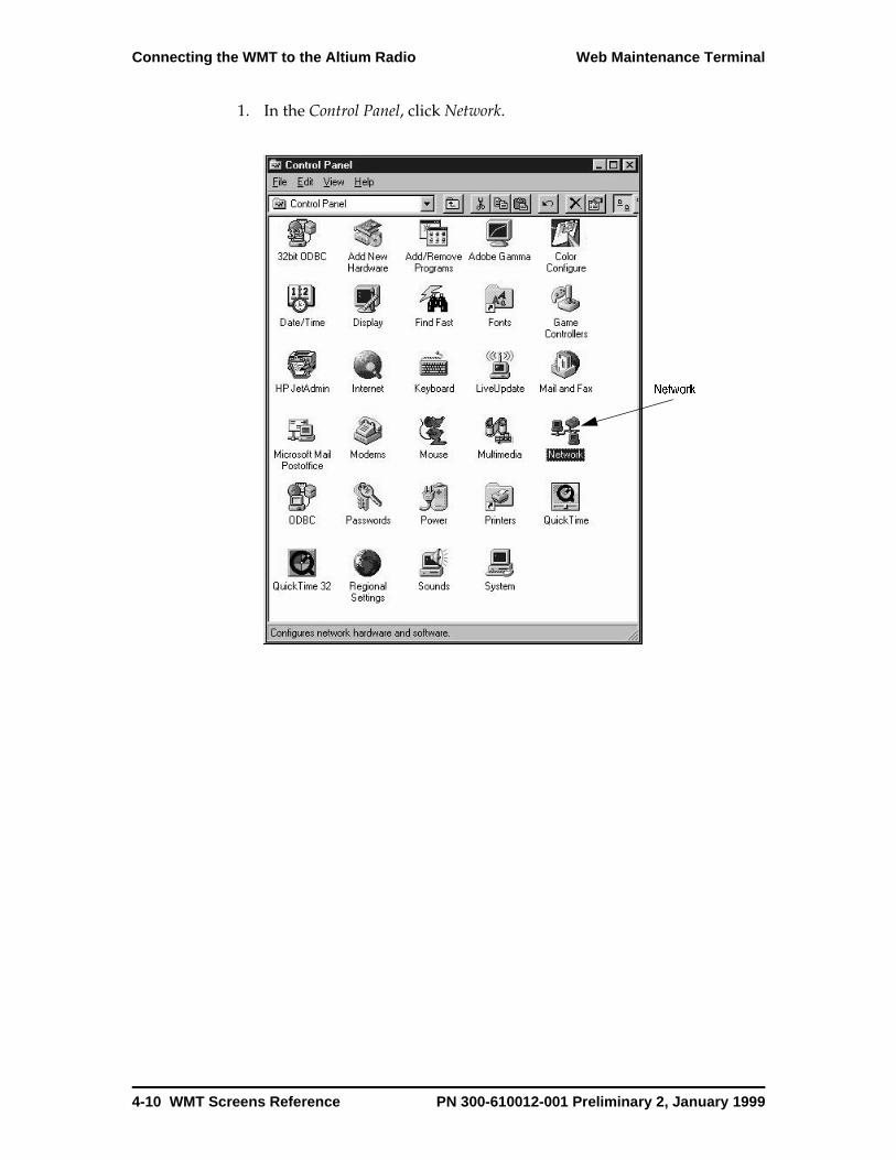
Connecting the WMT to the Altium Radio Web Maintenance Terminal
1. In the Control Panel, click Network.
Network
4-10 WMT Screens Reference PN 300-610012-001 Preliminary 2, January 1999
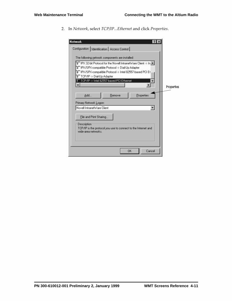
Web Maintenance Terminal Connecting the WMT to the Altium Radio
2. In Network, select TCP/IP...Ethernet and click Properties.
Properties
PN 300-610012-001 Preliminary 2, January 1999 WMT Screens Reference 4-11

Connecting the WMT to the Altium Radio Web Maintenance Terminal
3. In Properties, enter the IP Address, the Subnet Mask, and click OK.
First determine what the subnet mask is. Examine the IP address of the Altium radio. The IP address is printed on the ISAC module. Use the module’s extraction levers to pull the module out until you see the label with the IP address on it. Write the IP address down.
Referring to Table 4-2, examine the first byte of the IP address to determine the subnet mask.
Example: If the IP address of your Altium radio is 192.168.0.19, the first byte is 192. According to Table 4-2, the subnet mask is 255.255.255.0. This is the entry for Subnet Mask.
The IP address of your terminal is determined using the IP address of the
Table 4-2. Subnet Mask
First Byte of IP Address Subnet Mask
From 192 to 255 255.255.255.0
From 128 to 191 255.255.0.0
From 1 to 127 255.0.0.0
4-12 WMT Screens Reference PN 300-610012-001 Preliminary 2, January 1999
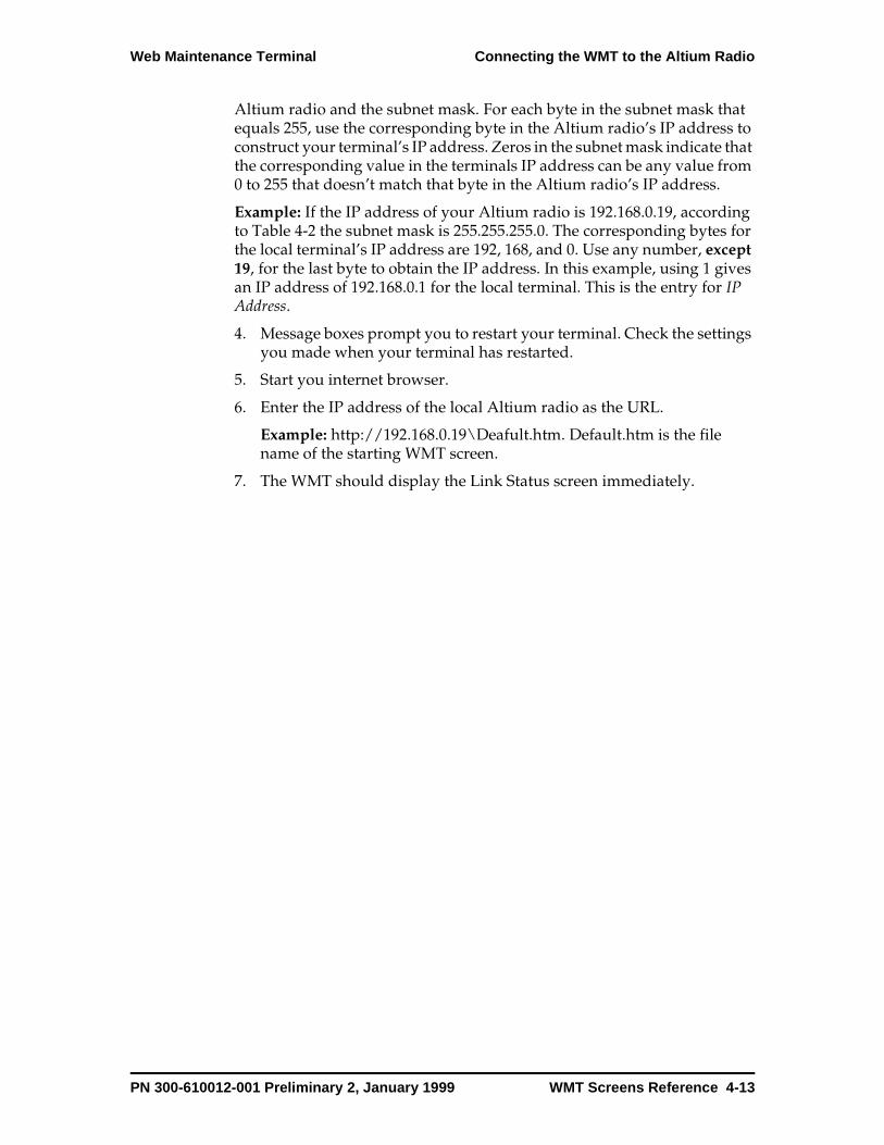
Web Maintenance Terminal Connecting the WMT to the Altium Radio
Altium radio and the subnet mask. For each byte in the subnet mask that equals 255, use the corresponding byte in the Altium radio’s IP address to construct your terminal’s IP address. Zeros in the subnet mask indicate that the corresponding value in the terminals IP address can be any value from 0 to 255 that doesn’t match that byte in the Altium radio’s IP address.
Example: If the IP address of your Altium radio is 192.168.0.19, according to Table 4-2 the subnet mask is 255.255.255.0. The corresponding bytes for the local terminal’s IP address are 192, 168, and 0. Use any number, except 19, for the last byte to obtain the IP address. In this example, using 1 gives an IP address of 192.168.0.1 for the local terminal. This is the entry for IP Address.
4. Message boxes prompt you to restart your terminal. Check the settings you made when your terminal has restarted.
5. Start you internet browser.
6. Enter the IP address of the local Altium radio as the URL.
Example: http://192.168.0.19\Deafult.htm. Default.htm is the file name of the starting WMT screen.
7. The WMT should display the Link Status screen immediately.
PN 300-610012-001 Preliminary 2, January 1999 WMT Screens Reference 4-13

Connecting the WMT to the Altium Radio Web Maintenance Terminal
Connecting through the MAINT ConnectorYou can make a serial connection to the Altium radio using an RS-232 cable to connect a COM port on your terminal to the MAINT connector on the Access Panel. This procedure also requires that you load a modem driver. The driver is on a floppy disk that comes with the Altium radio.
This procedure must be completed once.
1. Open the Control Panel (Start|Settings|Contol Panel)
2. In the Control Panel click Modems.
Modem
4-14 WMT Screens Reference PN 300-610012-001 Preliminary 2, January 1999
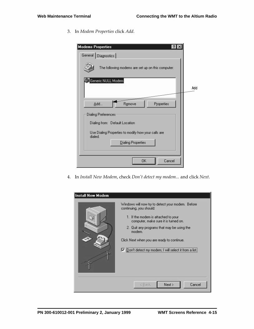
Web Maintenance Terminal Connecting the WMT to the Altium Radio
3. In Modem Properties click Add.
4. In Install New Modem, check Don’t detect my modem... and click Next.
Add
PN 300-610012-001 Preliminary 2, January 1999 WMT Screens Reference 4-15
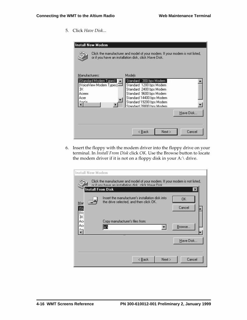
Connecting the WMT to the Altium Radio Web Maintenance Terminal
5. Click Have Disk...
6. Insert the floppy with the modem driver into the floppy drive on your terminal. In Install From Disk click OK. Use the Browse button to locate the modem driver if it is not on a floppy disk in your A:\ drive.
4-16 WMT Screens Reference PN 300-610012-001 Preliminary 2, January 1999
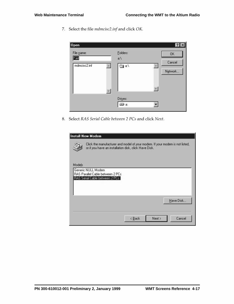
Web Maintenance Terminal Connecting the WMT to the Altium Radio
7. Select the file mdmcisc2.inf and click OK.
8. Select RAS Serial Cable between 2 PCs and click Next.
PN 300-610012-001 Preliminary 2, January 1999 WMT Screens Reference 4-17
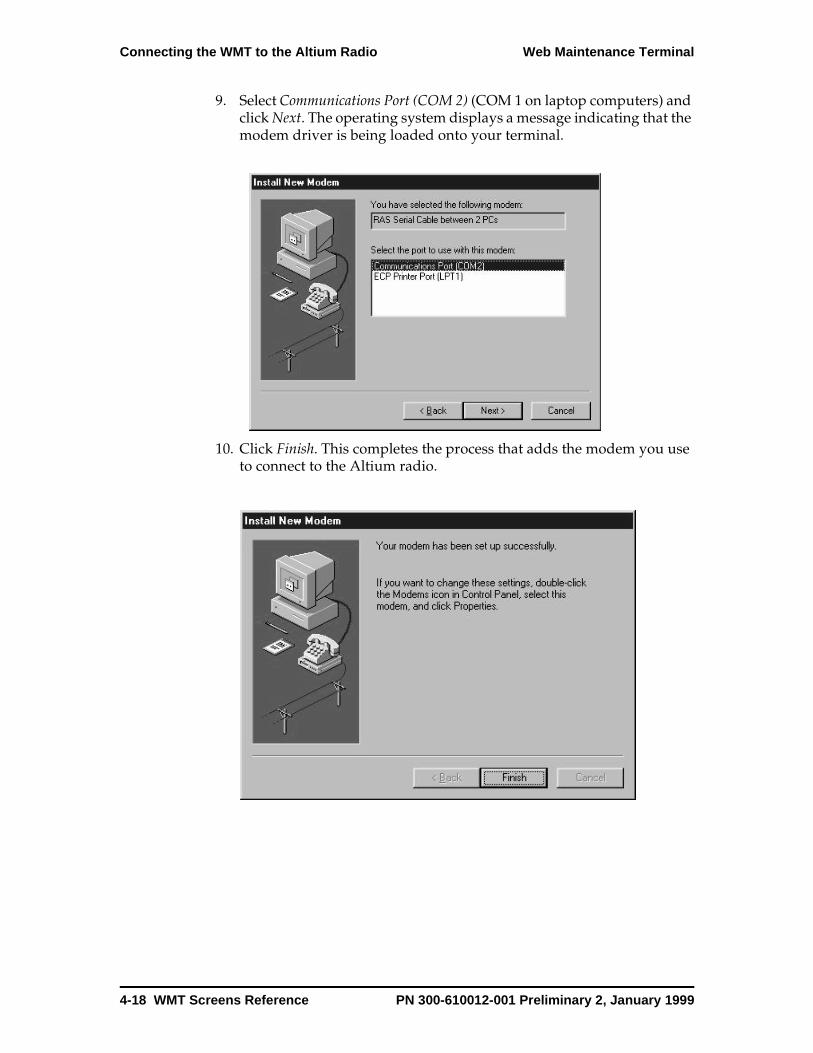
Connecting the WMT to the Altium Radio Web Maintenance Terminal
9. Select Communications Port (COM 2) (COM 1 on laptop computers) and click Next. The operating system displays a message indicating that the modem driver is being loaded onto your terminal.
10. Click Finish. This completes the process that adds the modem you use to connect to the Altium radio.
4-18 WMT Screens Reference PN 300-610012-001 Preliminary 2, January 1999

Web Maintenance Terminal Connecting the WMT to the Altium Radio
11. In Modem Properties, select RAS Serial Cable between 2 PCs and click Properties.
PN 300-610012-001 Preliminary 2, January 1999 WMT Screens Reference 4-19

Connecting the WMT to the Altium Radio Web Maintenance Terminal
12. Select 57600 for Maximum speed and click OK.
4-20 WMT Screens Reference PN 300-610012-001 Preliminary 2, January 1999

Web Maintenance Terminal Connecting the WMT to the Altium Radio
13. Click Advanced.
14. Deselect Use flow control. Click Ok, OK to return to Modem Properties.
PN 300-610012-001 Preliminary 2, January 1999 WMT Screens Reference 4-21

Connecting the WMT to the Altium Radio Web Maintenance Terminal
15. Click Close.
At this point, you have created a modem you can use to connect to the Altium system. You must add the modem to Dial-Up Networking.
1. Open Dial-Up Networking (My Computer|Dial-Up Networking).
4-22 WMT Screens Reference PN 300-610012-001 Preliminary 2, January 1999
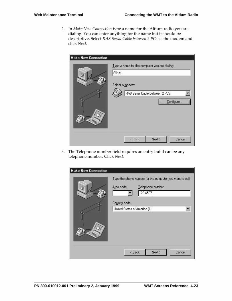
Web Maintenance Terminal Connecting the WMT to the Altium Radio
2. In Make New Connection type a name for the Altium radio you are dialing. You can enter anything for the name but it should be descriptive. Select RAS Serial Cable between 2 PCs as the modem and click Next.
3. The Telephone number field requires an entry but it can be any telephone number. Click Next.
PN 300-610012-001 Preliminary 2, January 1999 WMT Screens Reference 4-23
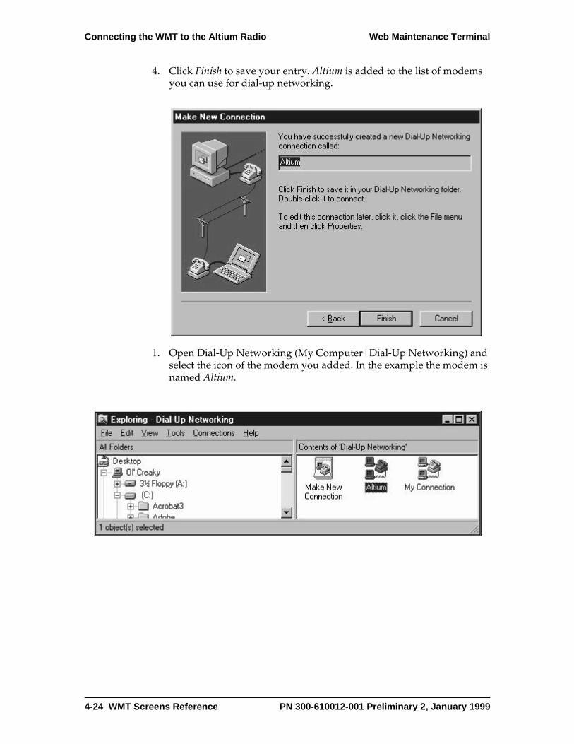
Connecting the WMT to the Altium Radio Web Maintenance Terminal
4. Click Finish to save your entry. Altium is added to the list of modems you can use for dial-up networking.
1. Open Dial-Up Networking (My Computer|Dial-Up Networking) and select the icon of the modem you added. In the example the modem is named Altium.
4-24 WMT Screens Reference PN 300-610012-001 Preliminary 2, January 1999
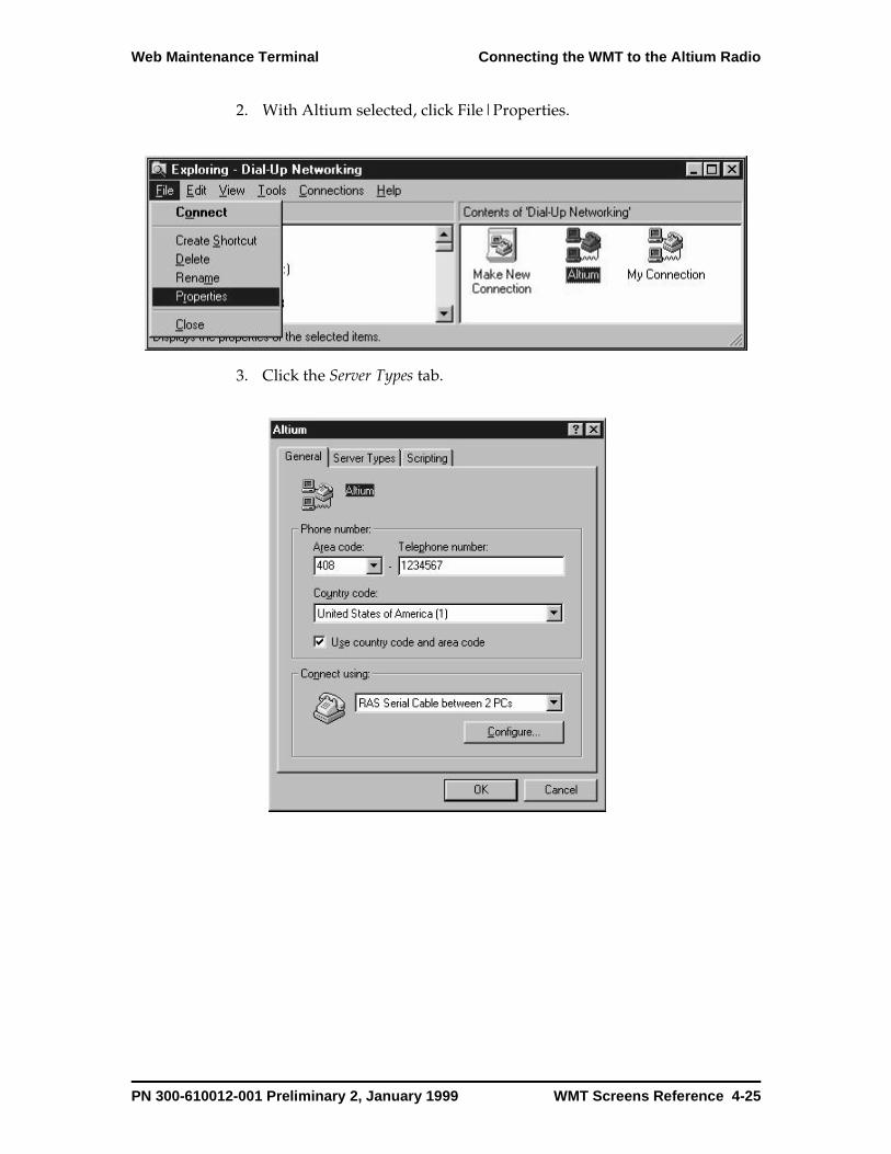
Web Maintenance Terminal Connecting the WMT to the Altium Radio
2. With Altium selected, click File|Properties.
3. Click the Server Types tab.
PN 300-610012-001 Preliminary 2, January 1999 WMT Screens Reference 4-25
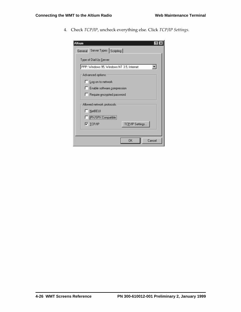
Connecting the WMT to the Altium Radio Web Maintenance Terminal
4. Check TCP/IP, uncheck everything else. Click TCP/IP Settings.
4-26 WMT Screens Reference PN 300-610012-001 Preliminary 2, January 1999

Web Maintenance Terminal Connecting the WMT to the Altium Radio
5. Enter any IP address except for the address of the Altium radio, for example 1.1.1.1. This is the IP address of the modem you added.
Do not use the Ethernet IP address of your terminal.
Check Use default gateway... and click OK, OK.
6. Double-click the modem you added.
PN 300-610012-001 Preliminary 2, January 1999 WMT Screens Reference 4-27
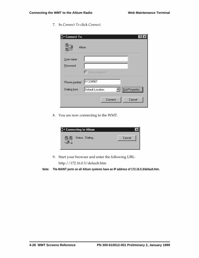
Connecting the WMT to the Altium Radio Web Maintenance Terminal
7. In Connect To click Connect.
8. You are now connecting to the WMT.
9. Start your browser and enter the following URL:
http://172.16.0.3/default.htm
Note: The MAINT ports on all Altium systems have an IP address of 172.16.0.3/default.htm.
4-28 WMT Screens Reference PN 300-610012-001 Preliminary 2, January 1999

Web Maintenance Terminal Connecting the WMT to the Altium Radio
Connecting to the Far End from the Local RadioWhen a connection is established with the local radio, you can connect the WMT to the far end radio.
1. In the Control Panel, click Network.
PN 300-610012-001 Preliminary 2, January 1999 WMT Screens Reference 4-29
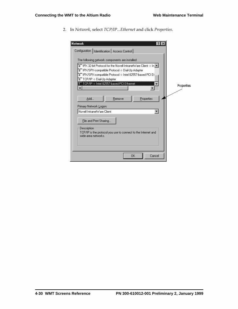
Connecting the WMT to the Altium Radio Web Maintenance Terminal
2. In Network, select TCP/IP...Ethernet and click Properties.
Properties
4-30 WMT Screens Reference PN 300-610012-001 Preliminary 2, January 1999
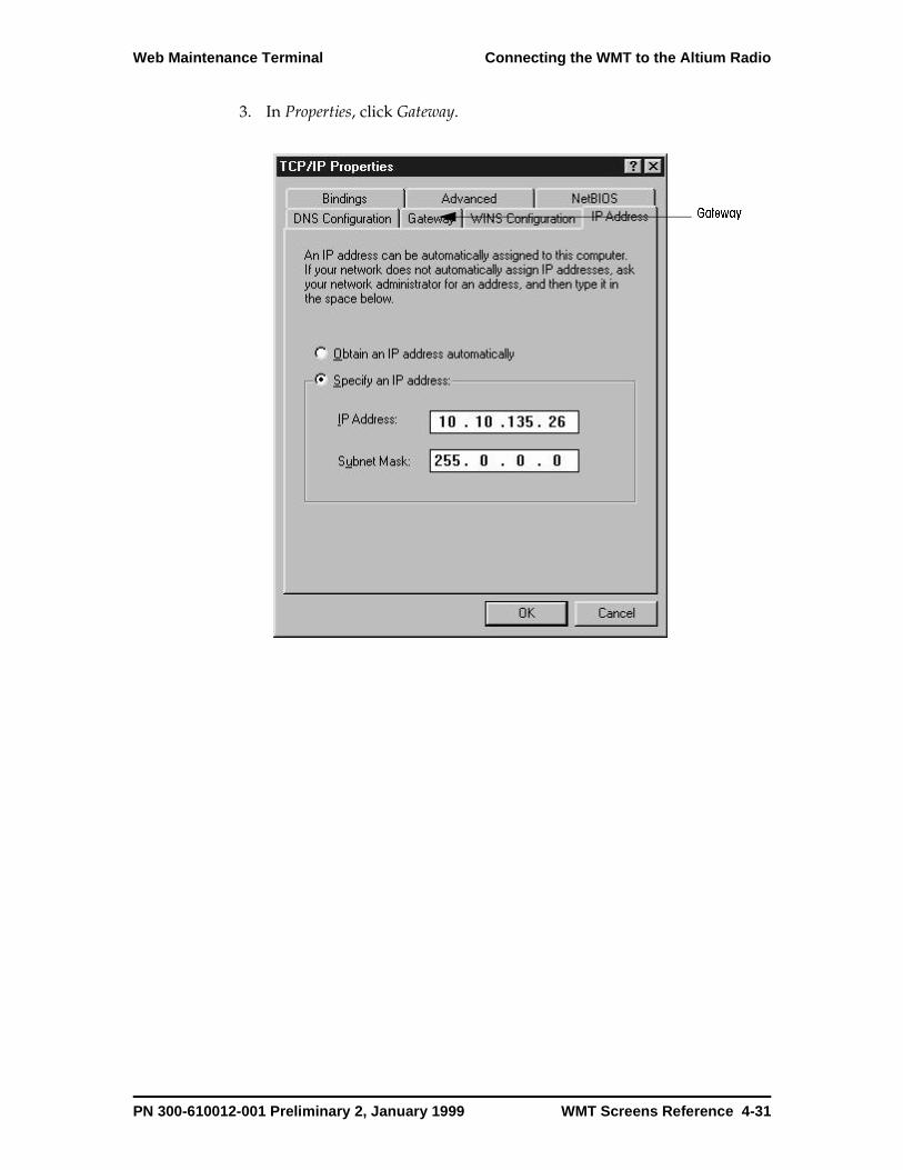
Web Maintenance Terminal Connecting the WMT to the Altium Radio
3. In Properties, click Gateway.
Gateway
PN 300-610012-001 Preliminary 2, January 1999 WMT Screens Reference 4-31
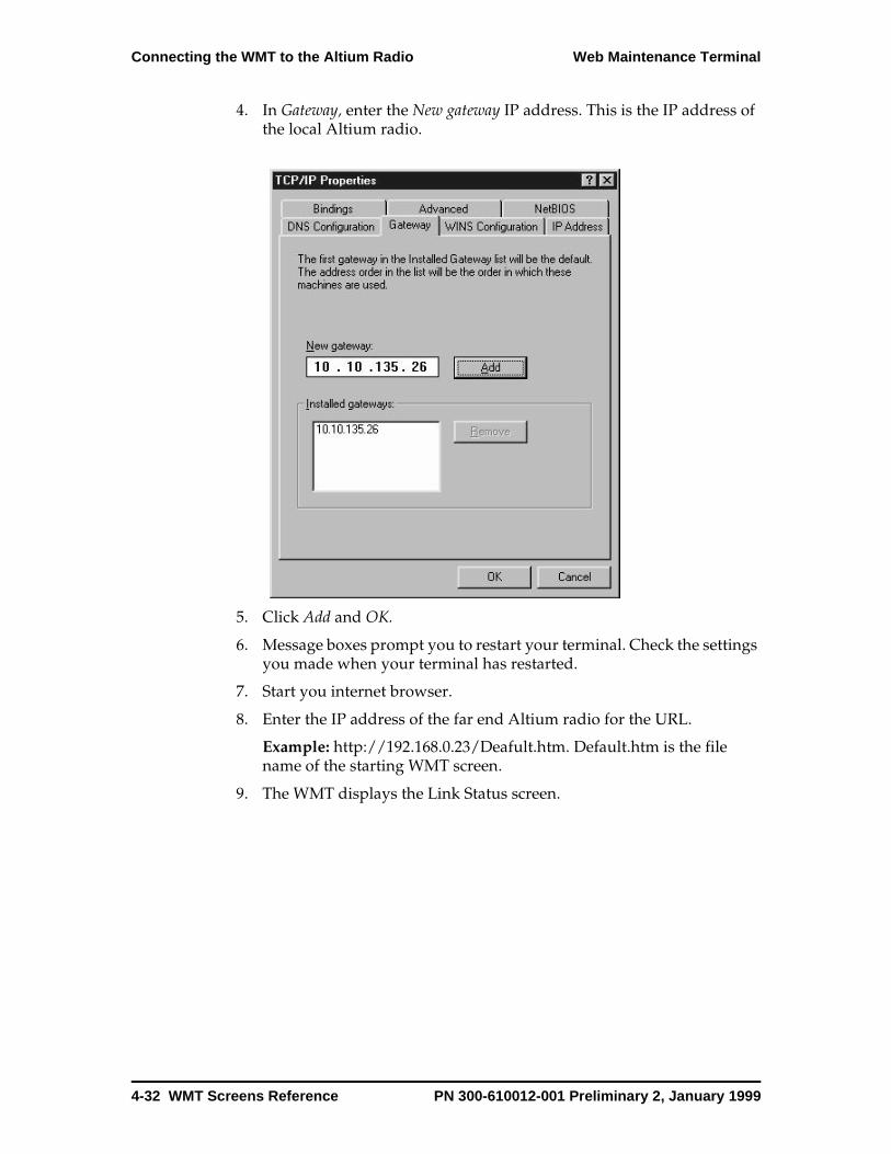
Connecting the WMT to the Altium Radio Web Maintenance Terminal
4. In Gateway, enter the New gateway IP address. This is the IP address of the local Altium radio.
5. Click Add and OK.
6. Message boxes prompt you to restart your terminal. Check the settings you made when your terminal has restarted.
7. Start you internet browser.
8. Enter the IP address of the far end Altium radio for the URL.
Example: http://192.168.0.23/Deafult.htm. Default.htm is the file name of the starting WMT screen.
9. The WMT displays the Link Status screen.
4-32 WMT Screens Reference PN 300-610012-001 Preliminary 2, January 1999
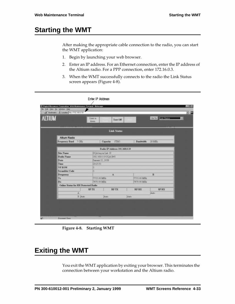
Web Maintenance Terminal Starting the WMT
Starting the WMT
After making the appropriate cable connection to the radio, you can start the WMT application:
1. Begin by launching your web browser.
2. Enter an IP address. For an Ethernet connection, enter the IP address of the Altium radio. For a PPP connection, enter 172.16.0.3.
3. When the WMT successfully connects to the radio the Link Status screen appears (Figure 4-8).
Figure 4-8. Starting WMT
Exiting the WMT
You exit the WMT application by exiting your browser. This terminates the connection between your workstation and the Altium radio.
Enter IP Address
PN 300-610012-001 Preliminary 2, January 1999 WMT Screens Reference 4-33
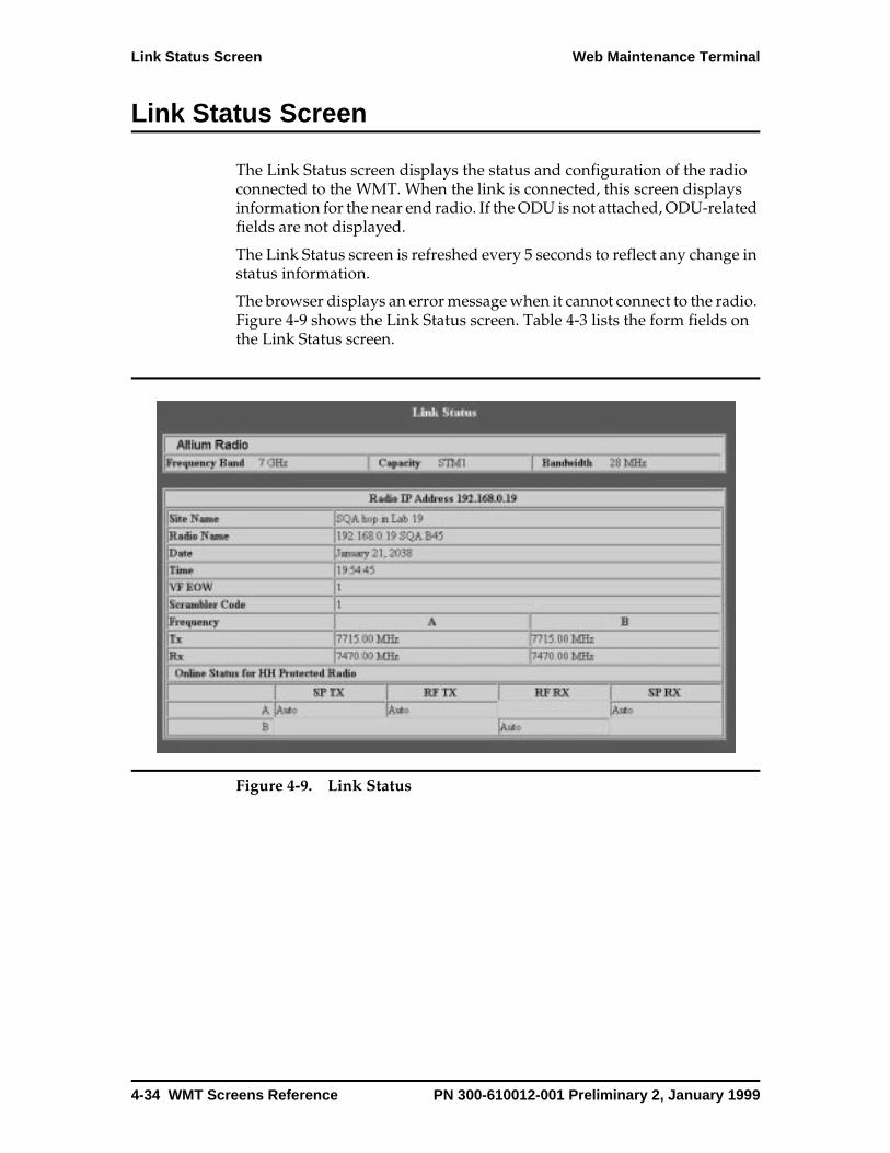
Link Status Screen Web Maintenance Terminal
Link Status Screen
The Link Status screen displays the status and configuration of the radio connected to the WMT. When the link is connected, this screen displays information for the near end radio. If the ODU is not attached, ODU-related fields are not displayed.
The Link Status screen is refreshed every 5 seconds to reflect any change in status information.
The browser displays an error message when it cannot connect to the radio. Figure 4-9 shows the Link Status screen. Table 4-3 lists the form fields on the Link Status screen.
Figure 4-9. Link Status
4-34 WMT Screens Reference PN 300-610012-001 Preliminary 2, January 1999
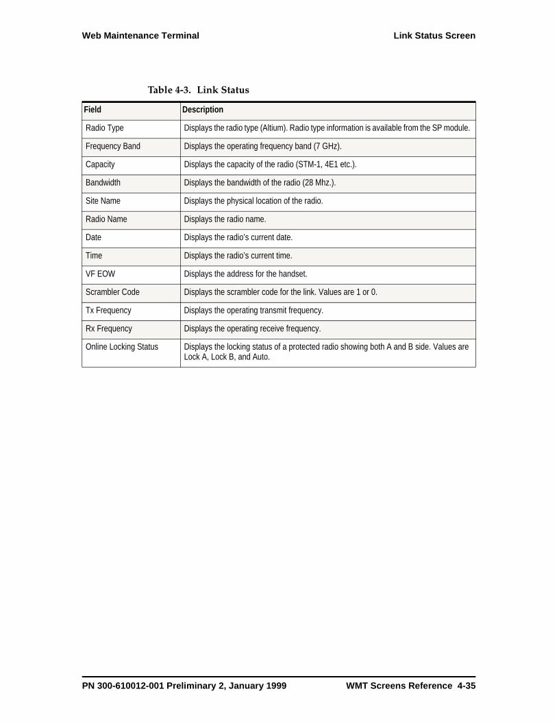
Web Maintenance Terminal Link Status Screen
Table 4-3. Link Status
Field Description
Radio Type Displays the radio type (Altium). Radio type information is available from the SP module.
Frequency Band Displays the operating frequency band (7 GHz).
Capacity Displays the capacity of the radio (STM-1, 4E1 etc.).
Bandwidth Displays the bandwidth of the radio (28 Mhz.).
Site Name Displays the physical location of the radio.
Radio Name Displays the radio name.
Date Displays the radio’s current date.
Time Displays the radio’s current time.
VF EOW Displays the address for the handset.
Scrambler Code Displays the scrambler code for the link. Values are 1 or 0.
Tx Frequency Displays the operating transmit frequency.
Rx Frequency Displays the operating receive frequency.
Online Locking Status Displays the locking status of a protected radio showing both A and B side. Values are Lock A, Lock B, and Auto.
PN 300-610012-001 Preliminary 2, January 1999 WMT Screens Reference 4-35

Configure Radios Screens Web Maintenance Terminal
Configure Radios Screens
The Altium system must be configured during installation. Initially, the Altium radio operating parameters must be set or default parameters changed on the near and far ends of the link, before the radios will work correctly. The Configure Radios screens allow you to configure radios on both ends of the link. Radio configuration is set through these screens:
• Link Information
• IDU
• Aux Data
• External Mux
• Relay
• SP
• TTL Input
• TTL Output
• VF Channel
• ODU
• RF Control
• RF Distribution Frequency
• RF Distribution Config
• Synthesizer
• Transceiver
• Network Management
• Maintenance Port
• Modem
• NMS
• NMS/Aux
• Phone Num
4-36 WMT Screens Reference PN 300-610012-001 Preliminary 2, January 1999

Web Maintenance Terminal Configure Radios Screens
Link Information ScreenYou use this form to set information that identifies the radio link. Figure 4-10 shows link information for the near end radio.
Figure 4-10. Link Information
Table 4-4. Link Information
Field Description
Radio type Displays the types of radios for the link.
Tx frequency Displays the transmit frequency for the radio.
Rx frequency Displays the receive frequency for the radio.
Site Name Enter the physical location of the terminal.
Radio Name Enter a name for the radio.
Comments Holds comments up to 96 characters long.
PN 300-610012-001 Preliminary 2, January 1999 WMT Screens Reference 4-37
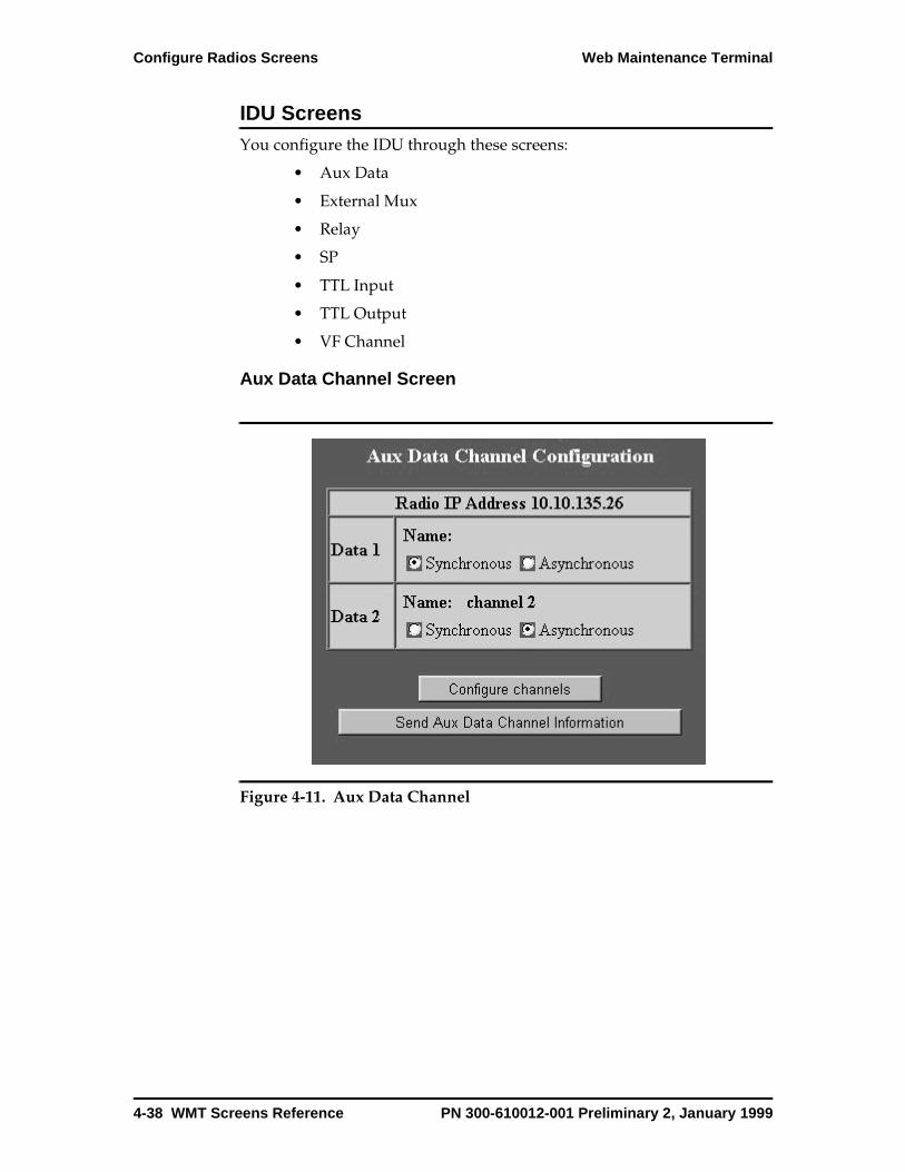
Configure Radios Screens Web Maintenance Terminal
IDU ScreensYou configure the IDU through these screens:
• Aux Data
• External Mux
• Relay
• SP
• TTL Input
• TTL Output
• VF Channel
Aux Data Channel Screen
Figure 4-11. Aux Data Channel
4-38 WMT Screens Reference PN 300-610012-001 Preliminary 2, January 1999
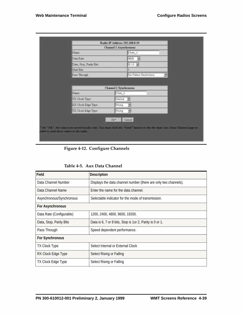
Web Maintenance Terminal Configure Radios Screens
Figure 4-12. Configure Channels
Table 4-5. Aux Data Channel
Field Description
Data Channel Number Displays the data channel number (there are only two channels).
Data Channel Name Enter the name for the data channel.
Asynchronous/Synchronous Selectable indicator for the mode of transmission.
For Asynchronous
Data Rate (Configurable) 1200, 2400, 4800, 9600, 19200.
Data, Stop, Parity Bits Data is 6, 7 or 8 bits, Stop is 1or 2, Parity is 0 or 1.
Pass Through Speed dependent performance.
For Synchronous
TX Clock Type Select Internal or External Clock
RX Clock Edge Type Select Rising or Falling
TX Clock Edge Type Select Rising or Falling
PN 300-610012-001 Preliminary 2, January 1999 WMT Screens Reference 4-39
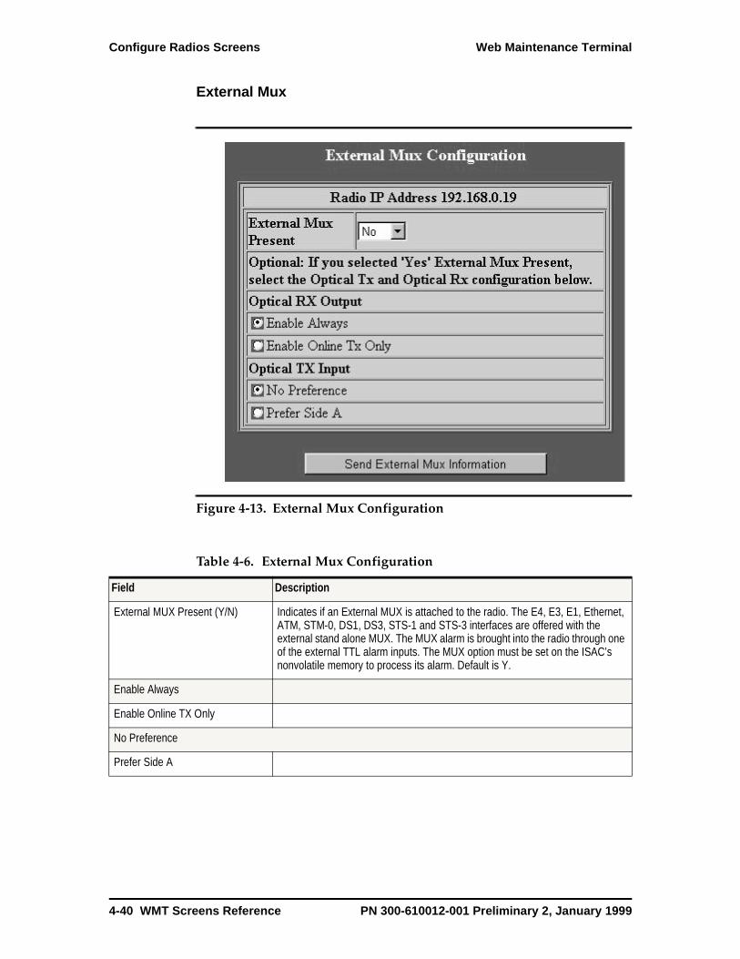
Configure Radios Screens Web Maintenance Terminal
External Mux
Figure 4-13. External Mux Configuration
Table 4-6. External Mux Configuration
Field Description
External MUX Present (Y/N) Indicates if an External MUX is attached to the radio. The E4, E3, E1, Ethernet, ATM, STM-0, DS1, DS3, STS-1 and STS-3 interfaces are offered with the external stand alone MUX. The MUX alarm is brought into the radio through one of the external TTL alarm inputs. The MUX option must be set on the ISAC’s nonvolatile memory to process its alarm. Default is Y.
Enable Always
Enable Online TX Only
No Preference
Prefer Side A
4-40 WMT Screens Reference PN 300-610012-001 Preliminary 2, January 1999

Web Maintenance Terminal Configure Radios Screens
Relay Configuration
Figure 4-14. Relay Configuration
Table 4-7. Relay Configuration
Field Description
Number Displays the relay number (1-4).
Name Enter a name for each relay. It is helpful to use the name of the terminating (alarm) equipment.
Type Displays Latched or Unlatched. Unlatched is default to Major and Minor. Latched may be set by the user to Major Fault, Minor Fault, UNUSED, Force Open, or Force Close
Alarm Unused - Select for a relay is not in use. No fault conditions are tracked or activated. Thissetting and the Forced Open setting are the same.
Force Open - Select to set a relay open. No fault conditions are tracked or activated. Thissetting and the Unused Setting are the same.
Force Closed - A user can temporarily disable fault alerts on this relay, perhaps whenperforming maintenance on the associated alarm equipment. With the relay closed, no faultconditions are tracked or activated.
Major Fault - This condition indicates a catastrophic fault condition; there is loss of trafficacross the link. In a protected radio, the backup radio is placed in service automatically. Ifthis corrects the problem, the fault is reported as a Minor Fault.
Minor Fault - This indicates that there is a guarded fault in a radio. A minor Fault does notnecessarily mean that there is a loss of traffic or downtime. The loss of tributary input isreported as a minor fault even though there is a loss of traffic. Examples of minor faults areIDU Fan Fault and ODU Temperature Fault.
Status Displays Set or Clear
PN 300-610012-001 Preliminary 2, January 1999 WMT Screens Reference 4-41

Configure Radios Screens Web Maintenance Terminal
SP Configuration
Figure 4-15. SP Configuration
Table 4-8. SP Configuration
Field Description
Bandwidth Displays the current selected bandwidth. Values are:
3.5 MHz 3.75 MHz 7 MHz 10 MHz
14 MHz 28 MHz 30 MHz
Capacity Displays the current selected capacity of the radio. Values are:
4E1 4E1N 8E1 8E1N
16E1 16E1N STM0 STM0N
2E3 2E3N 4E3 4E3N
1E4 1E4N STM1 STM1W
4DS1 8DS1 12DS1 16DS1
28DS1 1DS3 3DS3
Select to change The SP ID PROM contains a set of values for the different bandwidth, capacity, and modulation combinations. By choosing the appropriate capacity and bandwidth combination, WMT software automatically selects the correct modulation.
Scrambler Code must be the same for the near and far ends.
4-42 WMT Screens Reference PN 300-610012-001 Preliminary 2, January 1999
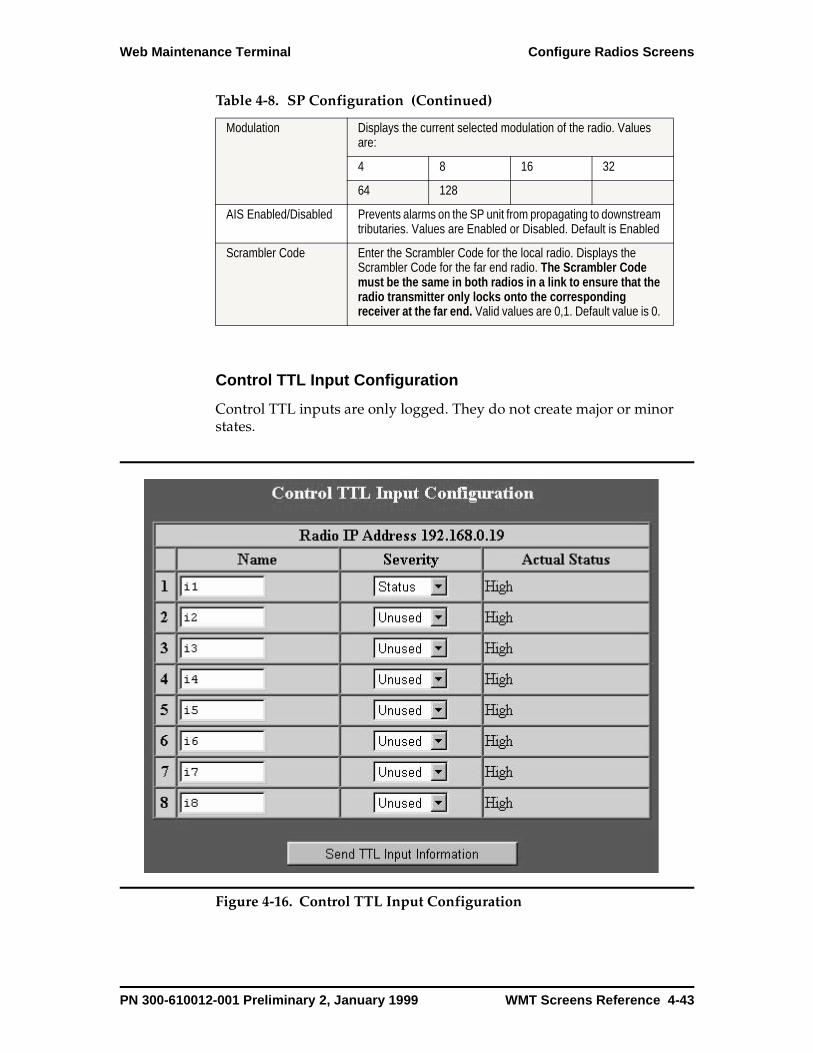
Web Maintenance Terminal Configure Radios Screens
Control TTL Input Configuration
Control TTL inputs are only logged. They do not create major or minor states.
Figure 4-16. Control TTL Input Configuration
Modulation Displays the current selected modulation of the radio. Values are:
4 8 16 32
64 128
AIS Enabled/Disabled Prevents alarms on the SP unit from propagating to downstream tributaries. Values are Enabled or Disabled. Default is Enabled
Scrambler Code Enter the Scrambler Code for the local radio. Displays the Scrambler Code for the far end radio. The Scrambler Code must be the same in both radios in a link to ensure that the radio transmitter only locks onto the corresponding receiver at the far end. Valid values are 0,1. Default value is 0.
Table 4-8. SP Configuration (Continued)
PN 300-610012-001 Preliminary 2, January 1999 WMT Screens Reference 4-43
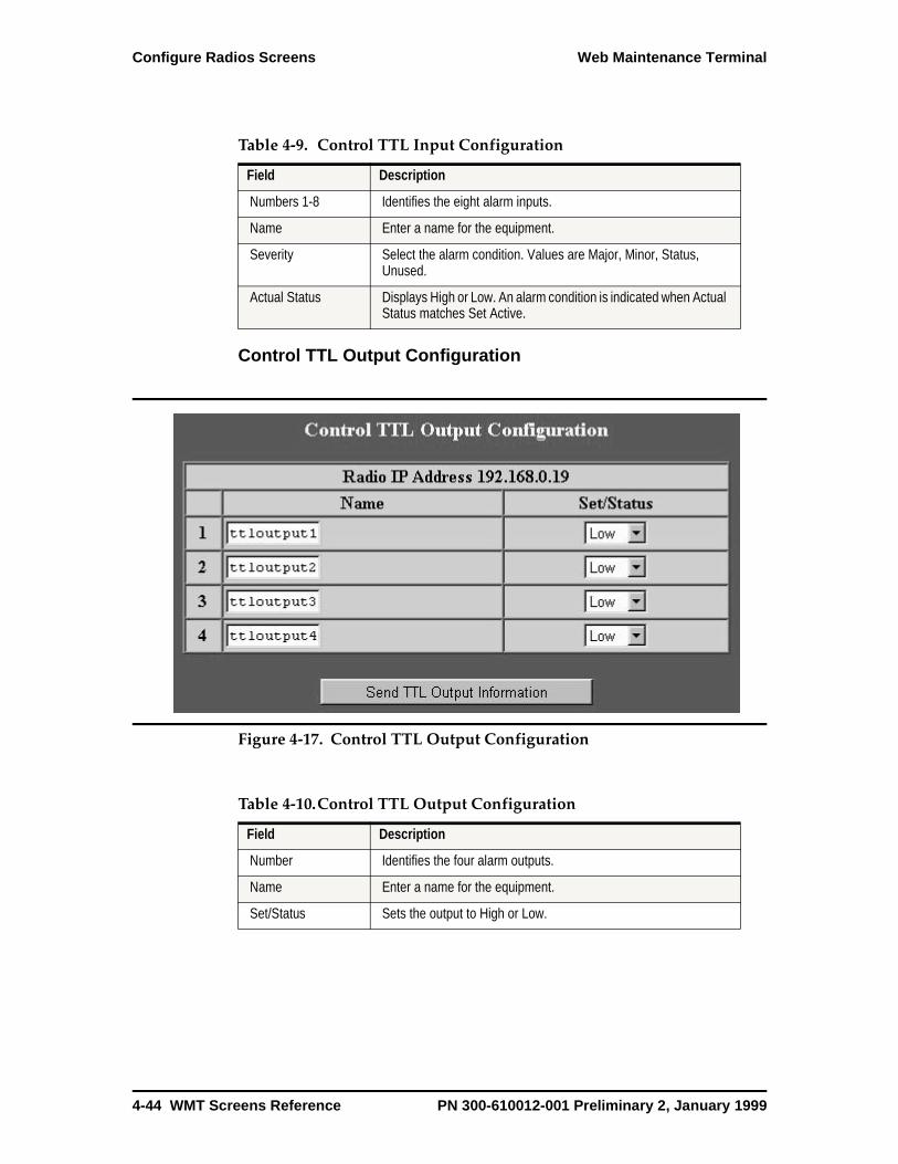
Configure Radios Screens Web Maintenance Terminal
Control TTL Output Configuration
Figure 4-17. Control TTL Output Configuration
Table 4-9. Control TTL Input Configuration
Field Description
Numbers 1-8 Identifies the eight alarm inputs.
Name Enter a name for the equipment.
Severity Select the alarm condition. Values are Major, Minor, Status, Unused.
Actual Status Displays High or Low. An alarm condition is indicated when Actual Status matches Set Active.
Table 4-10.Control TTL Output Configuration
Field Description
Number Identifies the four alarm outputs.
Name Enter a name for the equipment.
Set/Status Sets the output to High or Low.
4-44 WMT Screens Reference PN 300-610012-001 Preliminary 2, January 1999
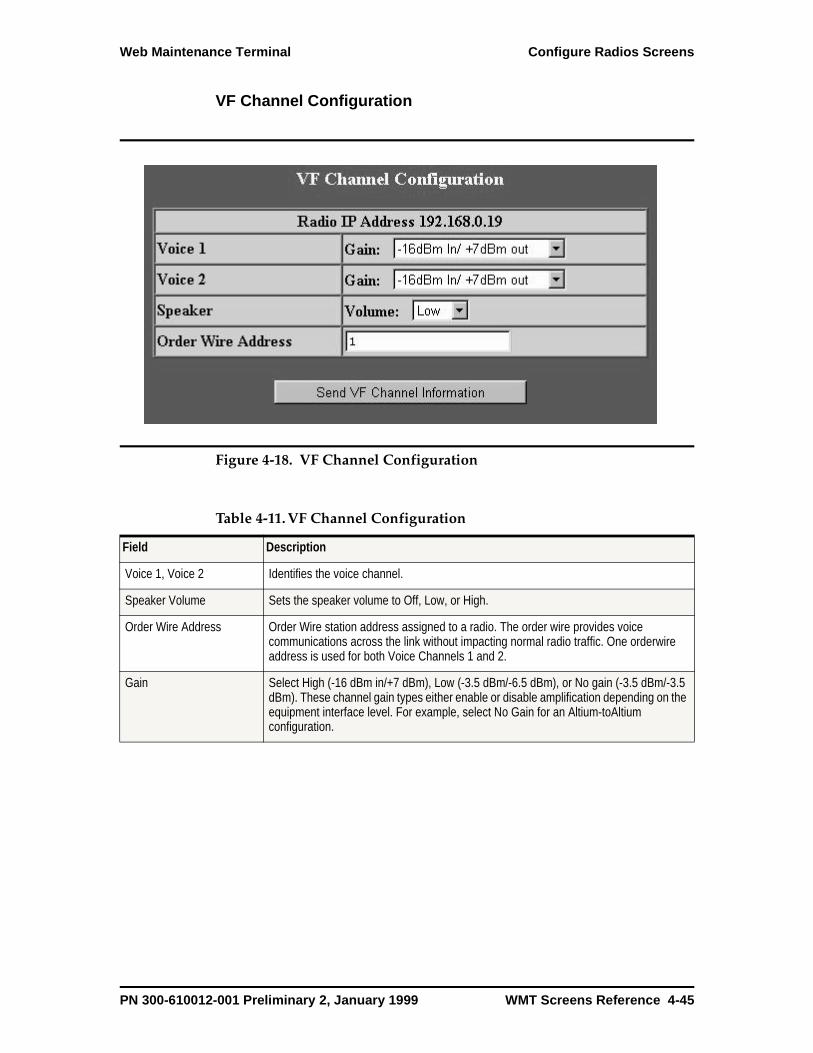
Web Maintenance Terminal Configure Radios Screens
VF Channel Configuration
Figure 4-18. VF Channel Configuration
Table 4-11.VF Channel Configuration
Field Description
Voice 1, Voice 2 Identifies the voice channel.
Speaker Volume Sets the speaker volume to Off, Low, or High.
Order Wire Address Order Wire station address assigned to a radio. The order wire provides voice communications across the link without impacting normal radio traffic. One orderwire address is used for both Voice Channels 1 and 2.
Gain Select High (-16 dBm in/+7 dBm), Low (-3.5 dBm/-6.5 dBm), or No gain (-3.5 dBm/-3.5 dBm). These channel gain types either enable or disable amplification depending on the equipment interface level. For example, select No Gain for an Altium-toAltium configuration.
PN 300-610012-001 Preliminary 2, January 1999 WMT Screens Reference 4-45

Configure Radios Screens Web Maintenance Terminal
ODU ScreensYou configure the ODU through these screens:
• RF Control
• RF Distribution Frequency
• RF Distribution Config
• Synthesizer
• Transceiver
RF Control
Figure 4-19. RF Control
4-46 WMT Screens Reference PN 300-610012-001 Preliminary 2, January 1999
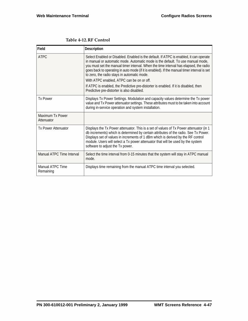
Web Maintenance Terminal Configure Radios Screens
Table 4-12.RF Control
Field Description
ATPC Select Enabled or Disabled. Enabled is the default. If ATPC is enabled, it can operate in manual or automatic mode. Automatic mode is the default. To use manual mode, you must set the manual timer interval. When the time interval has elapsed, the radio goes back to operating in auto mode (if it is enabled). If the manual timer interval is set to zero, the radio stays in automatic mode.With ATPC enabled, ATPC can be on or off. If ATPC is enabled, the Predictive pre-distorter is enabled. If it is disabled, then Predictive pre-distorter is also disabled.
Tx Power Displays Tx Power Settings. Modulation and capacity values determine the Tx power value and Tx Power attenuator settings. These attributes must to be taken into account during in-service operation and system installation.
Maximum Tx Power Attenuator
Tx Power Attenuator Displays the Tx Power attenuator. This is a set of values of Tx Power attenuator (in 1 db increments) which is determined by certain attributes of the radio. See Tx Power. Displays set of values in increments of 1 dBm which is derived by the RF control module. Users will select a Tx power attenuator that will be used by the system software to adjust the Tx power.
Manual ATPC Time Interval Select the time interval from 0-15 minutes that the system will stay in ATPC manual mode.
Manual ATPC Time Remaining
Displays time remaining from the manual ATPC time interval you selected.
PN 300-610012-001 Preliminary 2, January 1999 WMT Screens Reference 4-47
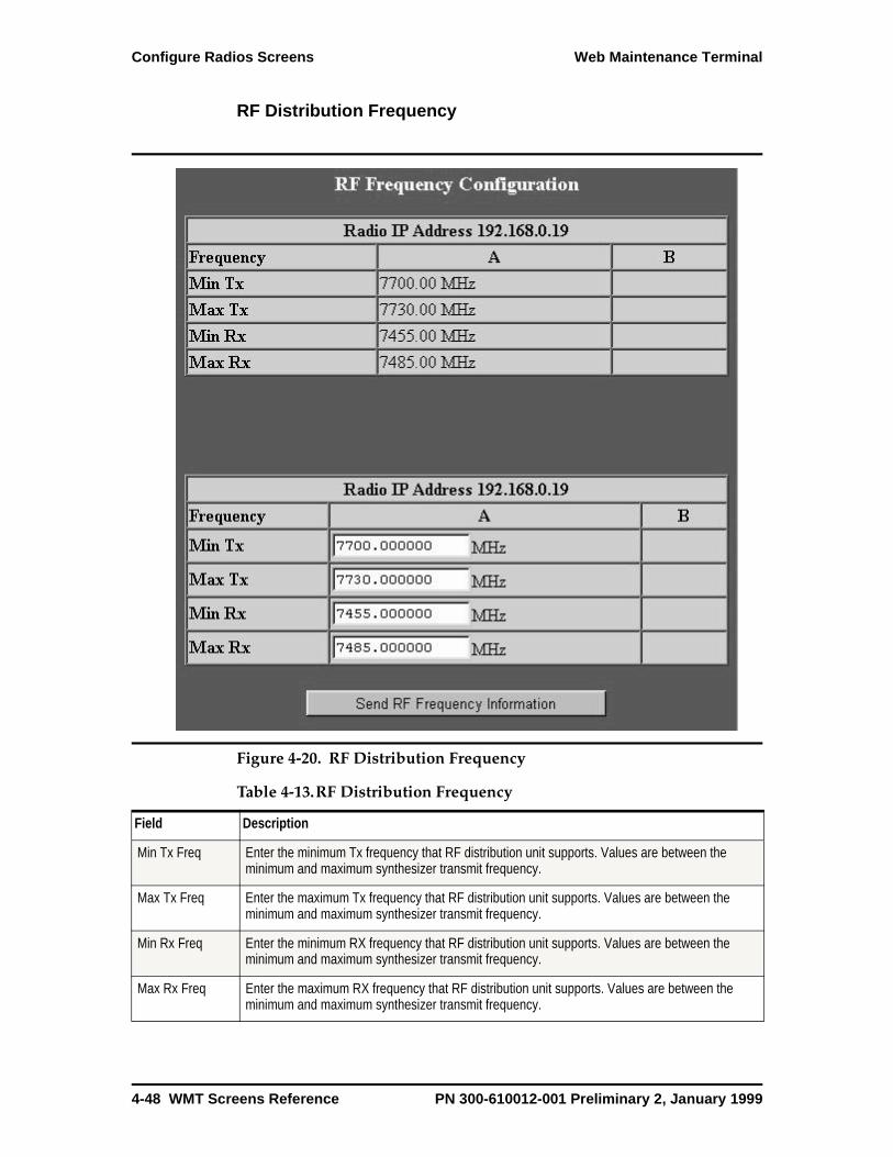
Configure Radios Screens Web Maintenance Terminal
RF Distribution Frequency
Figure 4-20. RF Distribution Frequency
Table 4-13.RF Distribution Frequency
Field Description
Min Tx Freq Enter the minimum Tx frequency that RF distribution unit supports. Values are between the minimum and maximum synthesizer transmit frequency.
Max Tx Freq Enter the maximum Tx frequency that RF distribution unit supports. Values are between the minimum and maximum synthesizer transmit frequency.
Min Rx Freq Enter the minimum RX frequency that RF distribution unit supports. Values are between the minimum and maximum synthesizer transmit frequency.
Max Rx Freq Enter the maximum RX frequency that RF distribution unit supports. Values are between the minimum and maximum synthesizer transmit frequency.
4-48 WMT Screens Reference PN 300-610012-001 Preliminary 2, January 1999
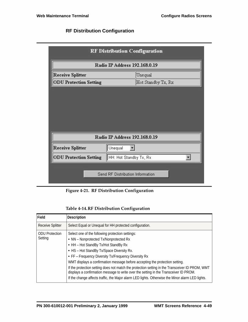
Web Maintenance Terminal Configure Radios Screens
RF Distribution Configuration
Figure 4-21. RF Distribution Configuration
Table 4-14.RF Distribution Configuration
Field Description
Receive Splitter Select Equal or Unequal for HH protected configuration.
ODU Protection Setting
Select one of the following protection settings: • NN – Nonprotected Tx/Nonprotected Rx• HH – Hot StandBy Tx/Hot StandBy Rx• HS – Hot StandBy Tx/Space Diversity Rx.• FF – Frequency Diversity Tx/Frequency Diversity RxWMT displays a confirmation message before accepting the protection setting.If the protection setting does not match the protection setting in the Transceiver ID PROM, WMT displays a confirmation message to write over the setting in the Transceiver ID PROM. If the change affects traffic, the Major alarm LED lights. Otherwise the Minor alarm LED lights.
PN 300-610012-001 Preliminary 2, January 1999 WMT Screens Reference 4-49
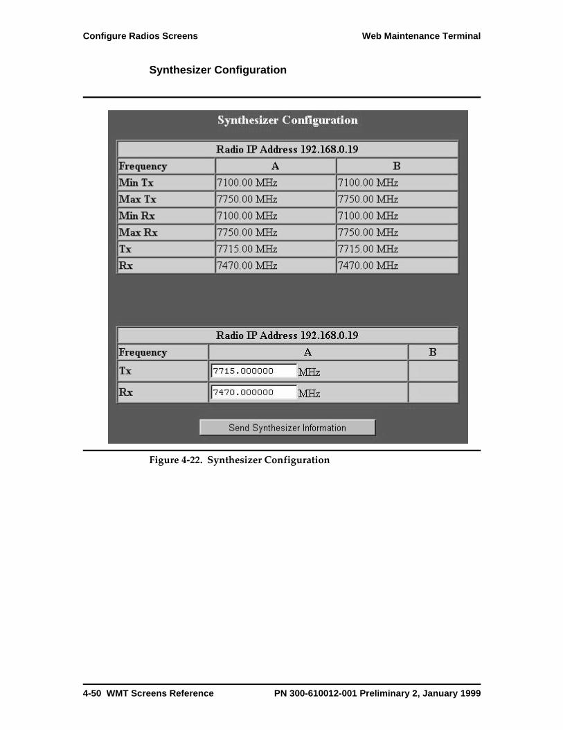
Configure Radios Screens Web Maintenance Terminal
Synthesizer Configuration
Figure 4-22. Synthesizer Configuration
4-50 WMT Screens Reference PN 300-610012-001 Preliminary 2, January 1999
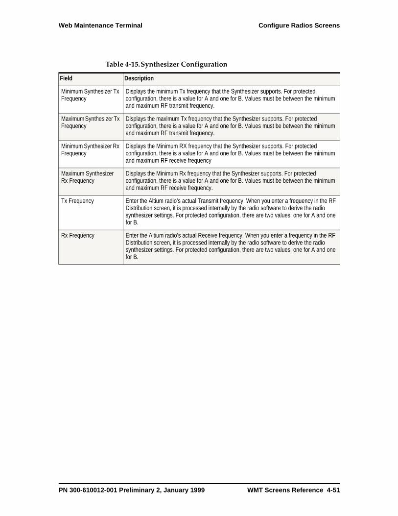
Web Maintenance Terminal Configure Radios Screens
Table 4-15.Synthesizer Configuration
Field Description
Minimum Synthesizer Tx Frequency
Displays the minimum Tx frequency that the Synthesizer supports. For protected configuration, there is a value for A and one for B. Values must be between the minimum and maximum RF transmit frequency.
Maximum Synthesizer Tx Frequency
Displays the maximum Tx frequency that the Synthesizer supports. For protected configuration, there is a value for A and one for B. Values must be between the minimum and maximum RF transmit frequency.
Minimum Synthesizer Rx Frequency
Displays the Minimum RX frequency that the Synthesizer supports. For protected configuration, there is a value for A and one for B. Values must be between the minimum and maximum RF receive frequency
Maximum Synthesizer Rx Frequency
Displays the Minimum Rx frequency that the Synthesizer supports. For protected configuration, there is a value for A and one for B. Values must be between the minimum and maximum RF receive frequency.
Tx Frequency Enter the Altium radio’s actual Transmit frequency. When you enter a frequency in the RF Distribution screen, it is processed internally by the radio software to derive the radio synthesizer settings. For protected configuration, there are two values: one for A and one for B.
Rx Frequency Enter the Altium radio’s actual Receive frequency. When you enter a frequency in the RF Distribution screen, it is processed internally by the radio software to derive the radio synthesizer settings. For protected configuration, there are two values: one for A and one for B.
PN 300-610012-001 Preliminary 2, January 1999 WMT Screens Reference 4-51
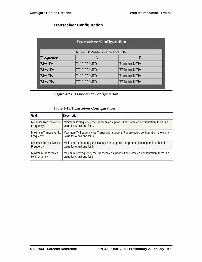
Configure Radios Screens Web Maintenance Terminal
Transceiver Configuration
Figure 4-23. Transceiver Configuration
Table 4-16.Transceiver Configuration
Field Description
Minimum Transceiver Tx Frequency
Minimum Tx frequency the Transceiver supports. For protected configuration, there is a value for A and one for B.
Maximum Transceiver Tx Frequency
Maximum Tx frequency the Transceiver supports. For protected configuration, there is a value for A and one for B.
Minimum Transceiver Rx Frequency
Minimum Rx frequency the Transceiver supports. For protected configuration, there is a value for A and one for B.
Maximum Transceiver Rx Frequency
Maximum Rx frequency the Transceiver supports. For protected configuration, there is a value for A and one for B.
4-52 WMT Screens Reference PN 300-610012-001 Preliminary 2, January 1999

Web Maintenance Terminal Configure Radios Screens
Network Management SystemYou configure NMS through these screens:
• Maintenance Port
• Modem
• NMS
• NMS/Aux
• Phone Num
Maintenance Port
Figure 4-24. Maintenance Port
PN 300-610012-001 Preliminary 2, January 1999 WMT Screens Reference 4-53

Configure Radios Screens Web Maintenance Terminal
Table 4-17.Maintenance Port
Field Description
Port Speed
Data Bits
Stop Bits
Port parity
Flow Control
Auto Baud
Receive ACC Map
Transmit ACC Map
No Modem List
Modem List 1
Modem List 2
No Phone List
Phone List 1
Phone List 2
4-54 WMT Screens Reference PN 300-610012-001 Preliminary 2, January 1999

Web Maintenance Terminal Configure Radios Screens
Modem Configuration
Figure 4-25. Modem Configuration
Table 4-18.Modem Configuration
Field Description
Select Modem List
Modem Setup Script
Modem Dial Script
Modem Hang-up Script
Modem Dial Mode
PN 300-610012-001 Preliminary 2, January 1999 WMT Screens Reference 4-55
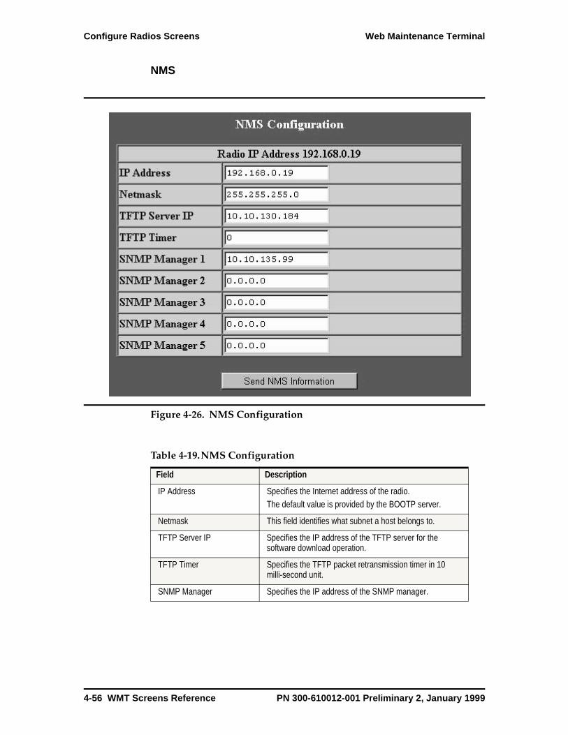
Configure Radios Screens Web Maintenance Terminal
NMS
Figure 4-26. NMS Configuration
Table 4-19.NMS Configuration
Field Description
IP Address Specifies the Internet address of the radio.The default value is provided by the BOOTP server.
Netmask This field identifies what subnet a host belongs to.
TFTP Server IP Specifies the IP address of the TFTP server for the software download operation.
TFTP Timer Specifies the TFTP packet retransmission timer in 10 milli-second unit.
SNMP Manager Specifies the IP address of the SNMP manager.
4-56 WMT Screens Reference PN 300-610012-001 Preliminary 2, January 1999
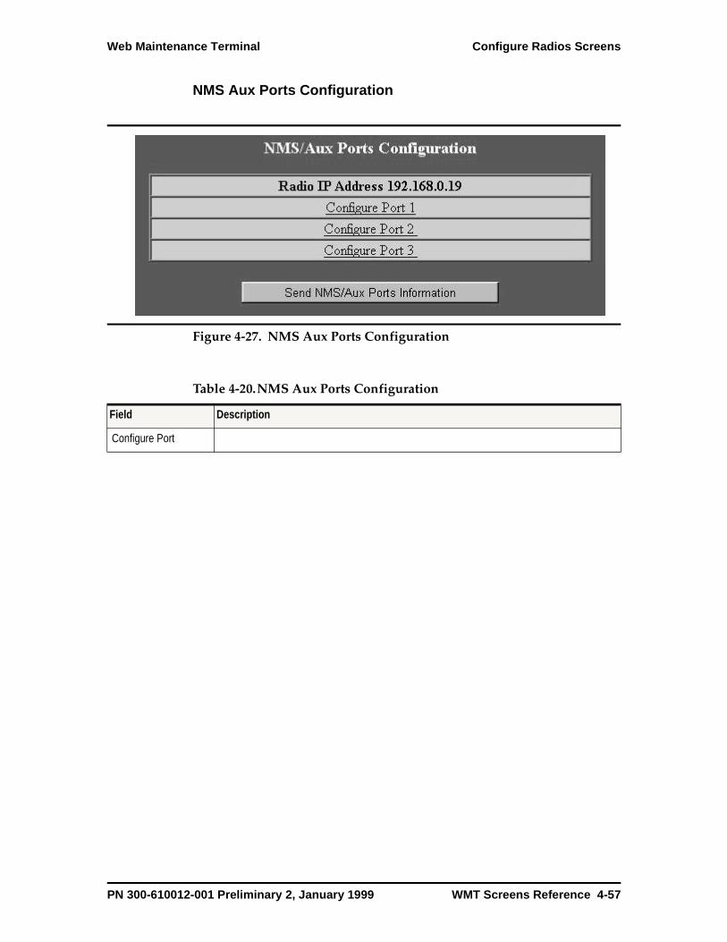
Web Maintenance Terminal Configure Radios Screens
NMS Aux Ports Configuration
Figure 4-27. NMS Aux Ports Configuration
Table 4-20.NMS Aux Ports Configuration
Field Description
Configure Port
PN 300-610012-001 Preliminary 2, January 1999 WMT Screens Reference 4-57

Configure Radios Screens Web Maintenance Terminal
Configure Port 1
Figure 4-28. Configure Port 1
Table 4-21.Aux Port Configuration
Field Description
Port Speed
Data Bits
Stop Bits
Port parity
Flow Control
No Modem List
Modem List 1
Modem List 2
No Phone List
Phone List 1
Phone List 2
4-58 WMT Screens Reference PN 300-610012-001 Preliminary 2, January 1999

Web Maintenance Terminal Events and Performance Screens
Events and Performance Screens
Events and performance are reported through the following screens:
• Active Events
• Complete Events
• Performance
• RSSI
• Radio Status
Active Events The Altium radio can store 512 events. Event fields are described in Table 4-22.
Figure 4-29. Active Events
PN 300-610012-001 Preliminary 2, January 1999 WMT Screens Reference 4-59
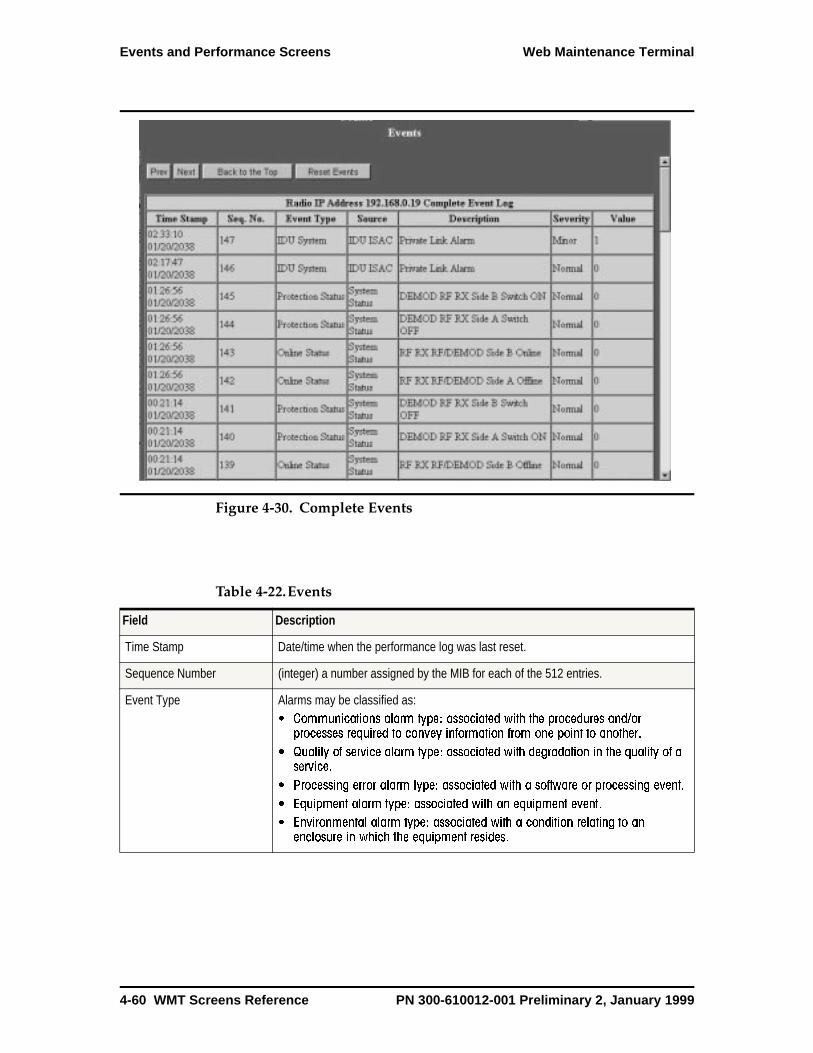
Events and Performance Screens Web Maintenance Terminal
Figure 4-30. Complete Events
Table 4-22.Events
Field Description
Time Stamp Date/time when the performance log was last reset.
Sequence Number (integer) a number assigned by the MIB for each of the 512 entries.
Event Type Alarms may be classified as: Communications alarm type: associated with the procedures and/or
processes required to convey information from one point to another.
Quality of service alarm type: associated with degradation in the quality of aservice.
Processing error alarm type: associated with a software or processing event.
Equipment alarm type: associated with an equipment event.
Environmental alarm type: associated with a condition relating to anenclosure in which the equipment resides.
4-60 WMT Screens Reference PN 300-610012-001 Preliminary 2, January 1999
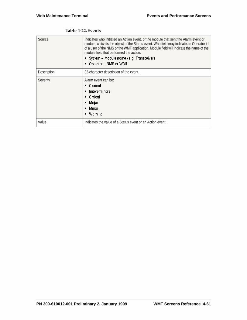
Web Maintenance Terminal Events and Performance Screens
Source Indicates who initiated an Action event, or the module that sent the Alarm event or module, which is the object of the Status event. Who field may indicate an Operator id of a user of the NMS or the WMT application. Module field will indicate the name of the module field that performed the action. System Module name (e.g. Transceiver)
Operator NMS or WMT
Description 32-character description of the event.
Severity Alarm event can be: Cleared
Indeterminate
Critical
Major
Minor
Warning
Value Indicates the value of a Status event or an Action event.
Table 4-22.Events
PN 300-610012-001 Preliminary 2, January 1999 WMT Screens Reference 4-61
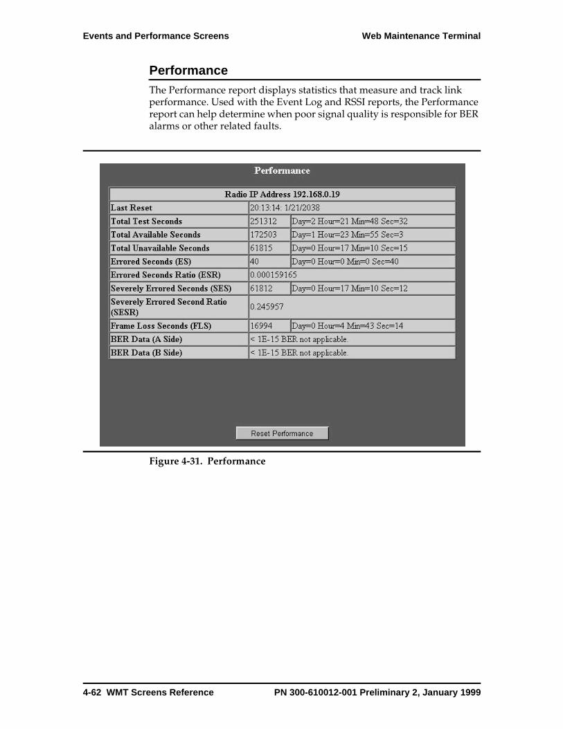
Events and Performance Screens Web Maintenance Terminal
Performance The Performance report displays statistics that measure and track link performance. Used with the Event Log and RSSI reports, the Performance report can help determine when poor signal quality is responsible for BER alarms or other related faults.
Figure 4-31. Performance
4-62 WMT Screens Reference PN 300-610012-001 Preliminary 2, January 1999
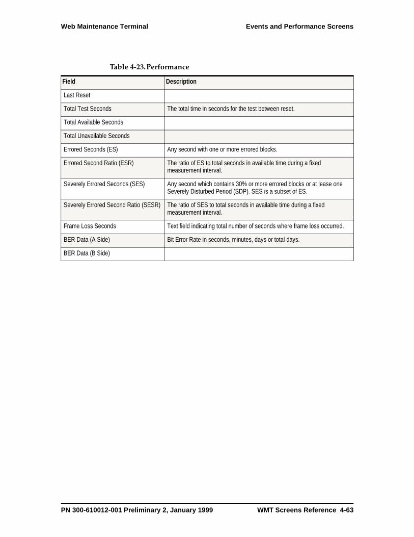
Web Maintenance Terminal Events and Performance Screens
Table 4-23.Performance
Field Description
Last Reset
Total Test Seconds The total time in seconds for the test between reset.
Total Available Seconds
Total Unavailable Seconds
Errored Seconds (ES) Any second with one or more errored blocks.
Errored Second Ratio (ESR) The ratio of ES to total seconds in available time during a fixed measurement interval.
Severely Errored Seconds (SES) Any second which contains 30% or more errored blocks or at lease one Severely Disturbed Period (SDP). SES is a subset of ES.
Severely Errored Second Ratio (SESR) The ratio of SES to total seconds in available time during a fixed measurement interval.
Frame Loss Seconds Text field indicating total number of seconds where frame loss occurred.
BER Data (A Side) Bit Error Rate in seconds, minutes, days or total days.
BER Data (B Side)
PN 300-610012-001 Preliminary 2, January 1999 WMT Screens Reference 4-63
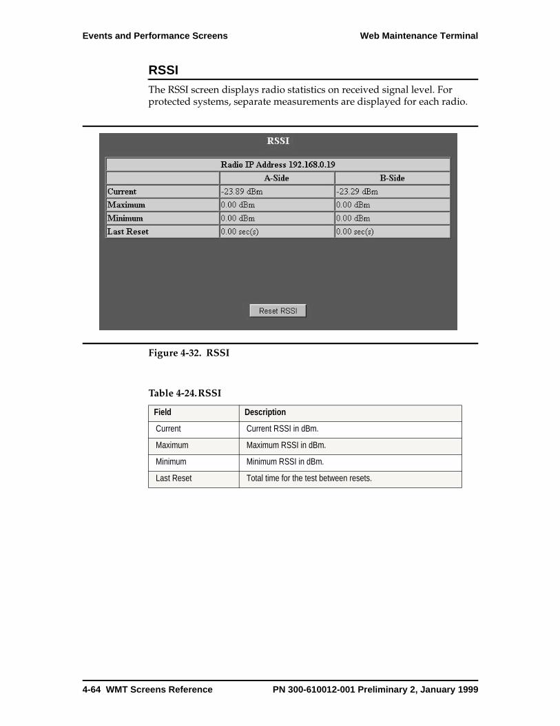
Events and Performance Screens Web Maintenance Terminal
RSSI The RSSI screen displays radio statistics on received signal level. For protected systems, separate measurements are displayed for each radio.
Figure 4-32. RSSI
Table 4-24.RSSI
Field Description
Current Current RSSI in dBm.
Maximum Maximum RSSI in dBm.
Minimum Minimum RSSI in dBm.
Last Reset Total time for the test between resets.
4-64 WMT Screens Reference PN 300-610012-001 Preliminary 2, January 1999

Web Maintenance Terminal Events and Performance Screens
Radio Status
Figure 4-33. Radio Status
Table 4-25.Radio Status
Field Description
IDU Temperature Internal temperature on SP module measured near the power supply.
ODU Temperature ODU RF Plug-in temperature measured on synthesizer card.
IDU Battery Voltage IDU power supply input voltage.
ODU Battery Voltage Odu power supply input voltage.
PN 300-610012-001 Preliminary 2, January 1999 WMT Screens Reference 4-65

Loopback Test Screen Web Maintenance Terminal
Loopback Test Screen
Loopback testing checks the continuity and basic operation of the radio system including the near end radio, the far end radio, and coaxial cables. Loopback tests are run from the near end radio using a test pattern generated either by the IDU or by externally connected equipment.
Figure 4-34. Loopback Tests
Table 4-26.Loopback Tests
Field Description
Test Type Valid test types are Local LIU
Remote LIU
IF - Local radio only.
Test Origin Valid test origins are Internal Test Generator or External Test Equipment.
View Test Diagram Allows the user to view loopback test diagram for the test type and test origin selected.
Tributary List The selectable tributaries and other channel types (Data, VF, WS, Trib) available for testing. When using an internal test generator, Data and VF channels are not available for test and only one line (Trib or WS) can be selected for testing. When using an external test generator, more than one line can be selected to test.
4-66 WMT Screens Reference PN 300-610012-001 Preliminary 2, January 1999

Web Maintenance Terminal Loopback Test Screen
Line Interface Unit (LIU) This loopback tests the transmit and receive section of the module for STM-1 continuity. LIU loopback testing can also be performed on a remote radio on an online module, which loops the receive data to the transmit path. This provides a two-way check of the STM-1 link. Running the LIU loopback test through the NMS facility tests continuity over several hops. The MAINT LED on the access panel blinks when loopback testing is in progress.
The on-board AIS clock can generate and detect a fixed test pattern. This internal loopback can be used to test the main and wayside channel without using external equipment.
Intermediate Frequency (IF) This loopback tests the entire transmit and receive paths of the IDU. The residual BER can be estimated using the FEC count. IF loopback tests affect all data traffic (unless it is performed on an off-line module).
WaysideNote: The wayside loopback does not apply to the STM-1/OC-3-only radio system.
This loopback provides a local test one channel at a time, checking the transmit and receive sections of the module for E1 continuity. This test can also be performed from a remote radio on an online module. The remote test loops the transmit and receive paths to provide a two-way check of E1 continuity over several radio hops. The wayside loopback test does not affect other data traffic. The internal loopback can check wayside performance without the use of external equipment.
AuxiliaryThis loopback checks the transmit and receive section on the module for AUX data continuity, one channel at a time. This test can also be performed from a remote radio on an online module. The remote test loops the
Run Test Click to start a loopback test. Accumulated statistics are not cleared automatically when a loopback test is started. You can clear statistics from the Performance screen. Starting a loopback test on a protected system where locking is set to Auto displays a warning message stating that locking must be set to Lock A or Lock B (depending on the SP unit selected). When the loopback test is completed, locking must be set back to Auto.
Stop Test Click to stop a loopback test. A radio reset also clears a loopback test.
Current bit errors The number of errors detected during the current refresh period.
Total accumulated errors The total number of errors detected during the entire test period.
Total elapsed time The elapsed test time in seconds since last reset.
Table 4-26.Loopback Tests
PN 300-610012-001 Preliminary 2, January 1999 WMT Screens Reference 4-67
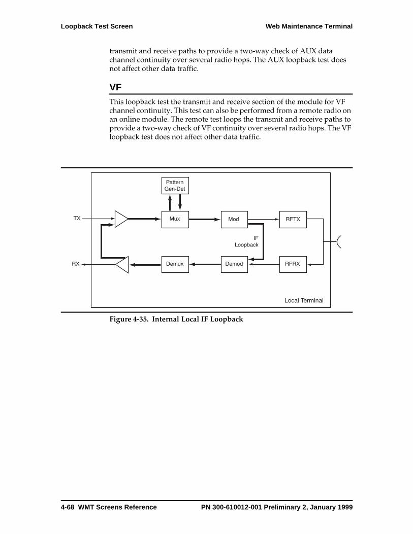
Loopback Test Screen Web Maintenance Terminal
transmit and receive paths to provide a two-way check of AUX data channel continuity over several radio hops. The AUX loopback test does not affect other data traffic.
VFThis loopback test the transmit and receive section of the module for VF channel continuity. This test can also be performed from a remote radio on an online module. The remote test loops the transmit and receive paths to provide a two-way check of VF continuity over several radio hops. The VF loopback test does not affect other data traffic.
Figure 4-35. Internal Local IF Loopback
4-68 WMT Screens Reference PN 300-610012-001 Preliminary 2, January 1999
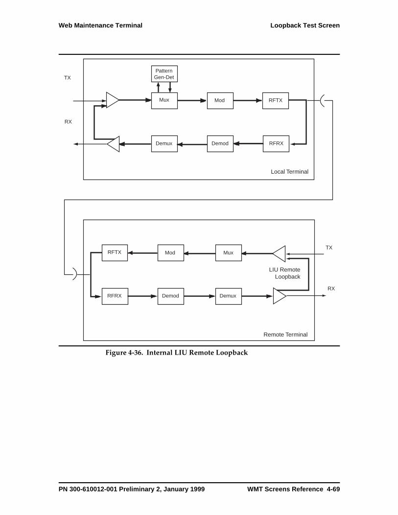
Web Maintenance Terminal Loopback Test Screen
Figure 4-36. Internal LIU Remote Loopback
Local Terminal
TX
Mux Mod RFTX
RFRXDemodDemux
PatternGen-Det
RX
Remote Terminal
RFTX Mod Mux
DemuxDemodRFRXRX
TX
LIU RemoteLoopback
PN 300-610012-001 Preliminary 2, January 1999 WMT Screens Reference 4-69
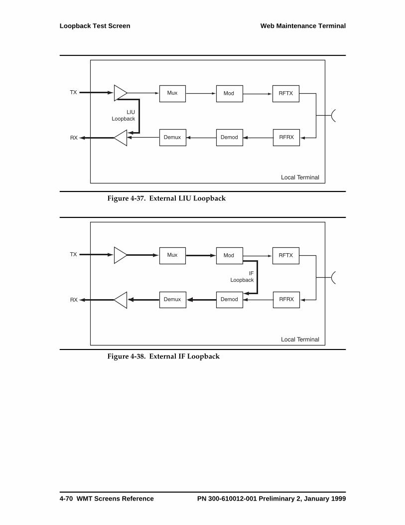
Loopback Test Screen Web Maintenance Terminal
Figure 4-37. External LIU Loopback
Figure 4-38. External IF Loopback
4-70 WMT Screens Reference PN 300-610012-001 Preliminary 2, January 1999
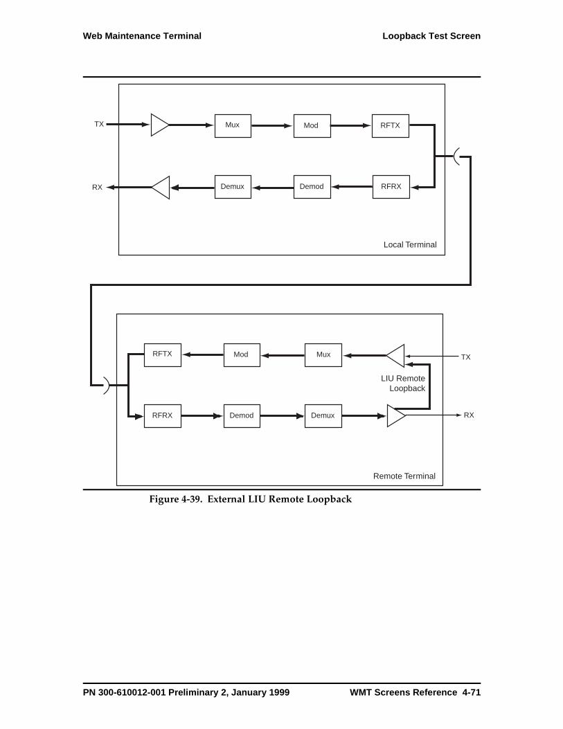
Web Maintenance Terminal Loopback Test Screen
Figure 4-39. External LIU Remote Loopback
Local Terminal
TX Mux Mod RFTX
RFRXDemodDemuxRX
Remote Terminal
RFTX Mod Mux
DemuxDemodRFRX RX
TX
LIU RemoteLoopback
PN 300-610012-001 Preliminary 2, January 1999 WMT Screens Reference 4-71
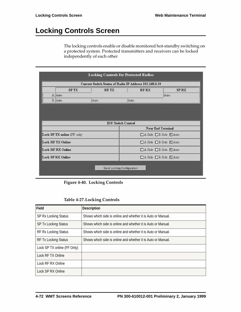
Locking Controls Screen Web Maintenance Terminal
Locking Controls Screen
The locking controls enable or disable monitored hot-standby switching on a protected system. Protected transmitters and receivers can be locked independently of each other
Figure 4-40. Locking Controls
Table 4-27.Locking Controls
Field Description
SP Rx Locking Status Shows which side is online and whether it is Auto or Manual.
SP Tx Locking Status Shows which side is online and whether it is Auto or Manual.
RF Rx Locking Status Shows which side is online and whether it is Auto or Manual.
RF Tx Locking Status Shows which side is online and whether it is Auto or Manual.
Lock SP TX online (FF Only)
Lock RF TX Online
Lock RF RX Online
Lock SP RX Online
4-72 WMT Screens Reference PN 300-610012-001 Preliminary 2, January 1999
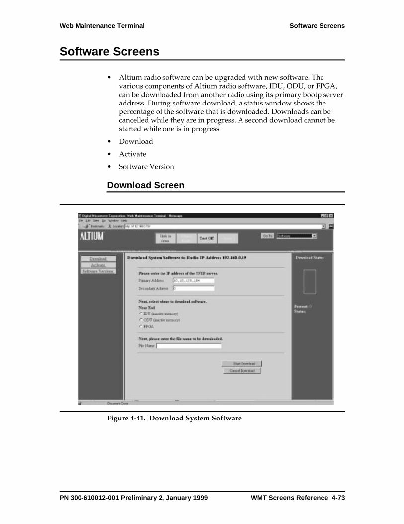
Web Maintenance Terminal Software Screens
Software Screens
• Altium radio software can be upgraded with new software. The various components of Altium radio software, IDU, ODU, or FPGA, can be downloaded from another radio using its primary bootp server address. During software download, a status window shows the percentage of the software that is downloaded. Downloads can be cancelled while they are in progress. A second download cannot be started while one is in progress
• Download
• Activate
• Software Version
Download Screen
Figure 4-41. Download System Software
PN 300-610012-001 Preliminary 2, January 1999 WMT Screens Reference 4-73
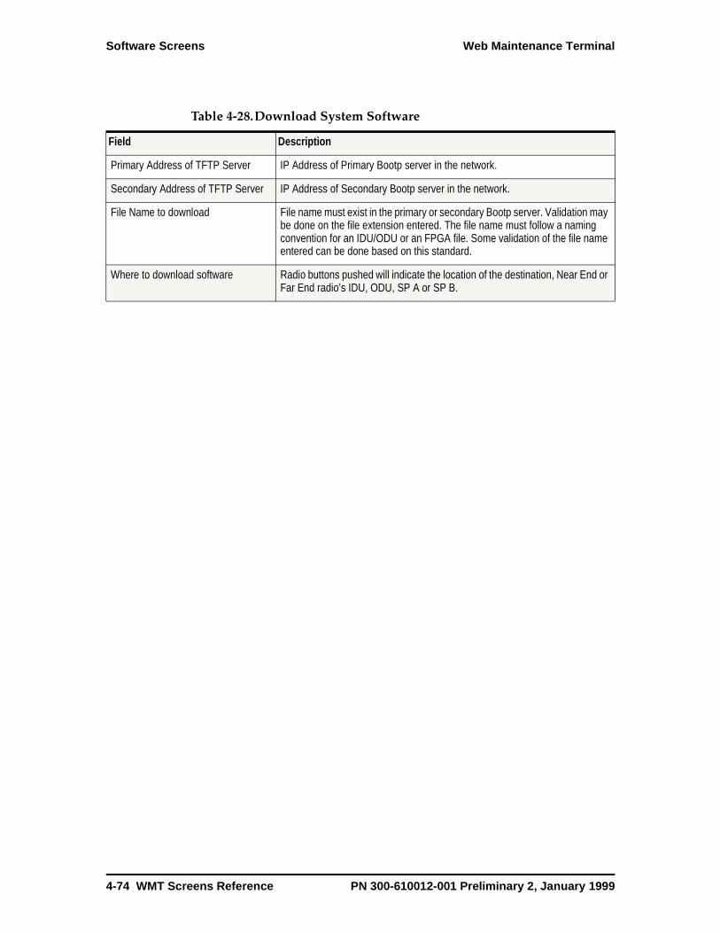
Software Screens Web Maintenance Terminal
Table 4-28.Download System Software
Field Description
Primary Address of TFTP Server IP Address of Primary Bootp server in the network.
Secondary Address of TFTP Server IP Address of Secondary Bootp server in the network.
File Name to download File name must exist in the primary or secondary Bootp server. Validation may be done on the file extension entered. The file name must follow a naming convention for an IDU/ODU or an FPGA file. Some validation of the file name entered can be done based on this standard.
Where to download software Radio buttons pushed will indicate the location of the destination, Near End or Far End radio’s IDU, ODU, SP A or SP B.
4-74 WMT Screens Reference PN 300-610012-001 Preliminary 2, January 1999
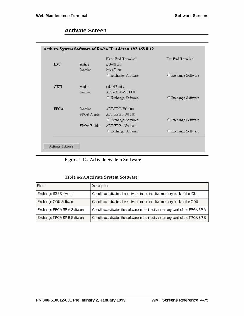
Web Maintenance Terminal Software Screens
Activate Screen
Figure 4-42. Activate System Software
Table 4-29.Activate System Software
Field Description
Exchange IDU Software Checkbox activates the software in the inactive memory bank of the IDU.
Exchange ODU Software Checkbox activates the software in the inactive memory bank of the ODU.
Exchange FPGA SP A Software Checkbox activates the software in the inactive memory bank of the FPGA SP A.
Exchange FPGA SP B Software Checkbox activates the software in the inactive memory bank of the FPGA SP B.
PN 300-610012-001 Preliminary 2, January 1999 WMT Screens Reference 4-75

Software Screens Web Maintenance Terminal
Software Versions Screen
Figure 4-43. Software Versions
Table 4-30.Software Versions
Field Description
Active IDU Software version IDU software version in the Active memory bank. Comes from ISAC EEPROM.
Inactive IDU Software version IDU software version in the inactive memory bank. Comes from ISAC EEPROM.
IDU Boot Software version IDU Boot software version.
Active ODU Software version ODU software version in the Active memory bank. Comes from OSAC EEPROM.
Inactive ODU Software version ODU software version in the inactive memory bank. Comes from OSAC EEPROM.
ODU Boot Software version ODU Boot software version.
Active FPGA SP A Software version
FPGA software version in Signal Processing A’s active memory bank. Comes from SP A EEPROM.
Inactive FPGA SP A Software version
FPGA software version in Signal Processing A’s inactive memory bank. Comes from SP A EEPROM.
Active FPGA SP B Software version
FPGA software version in Signal Processing B’s active memory bank. Comes from SP B EEPROM.
Inactive FPGA SP B Software version
FPGA software version in Signal Processing B’s inactive memory bank. Comes from SP B EEPROM.
4-76 WMT Screens Reference PN 300-610012-001 Preliminary 2, January 1999
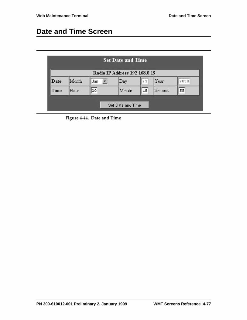
Web Maintenance Terminal Date and Time Screen
Date and Time Screen
Figure 4-44. Date and Time
PN 300-610012-001 Preliminary 2, January 1999 WMT Screens Reference 4-77
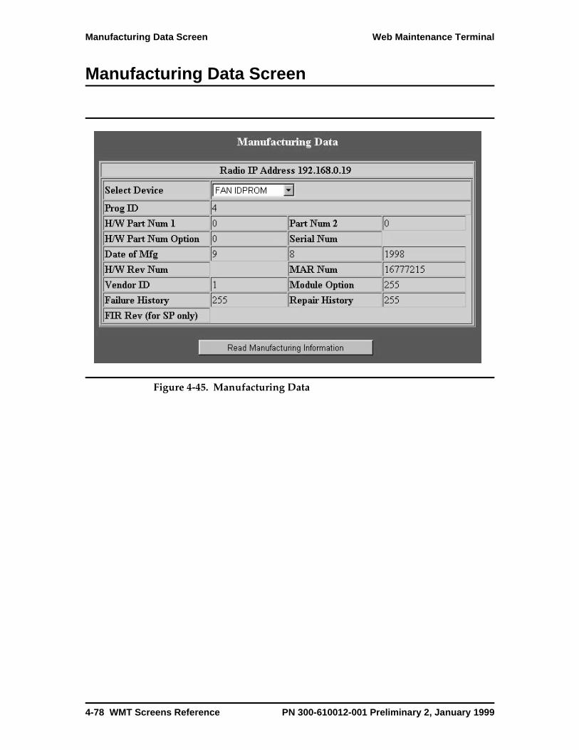
Manufacturing Data Screen Web Maintenance Terminal
Manufacturing Data Screen
Figure 4-45. Manufacturing Data
4-78 WMT Screens Reference PN 300-610012-001 Preliminary 2, January 1999
Chapter 5
System Descri ption
This chapter provides information on: the Altium system hardware; system functions and featuressuch as system configurations, protection switching, and ATPC (Automatic Transmit Power Control).
Overview
The ALTIUM microwave radio platform provides a telecommunications circuit that operates in the 7-38 GHz frequency range with a 25-28 MHz channel bandwidth. The Altium radio is transparent to the STM-1/OC-3 payload (155.55 Mbps). An Altium terminal consists of an IDU, ODU, IDU/ODU coaxial cable, and antenna. A link or hop consists of two terminals: the near end and its frequency-matched far end.
Altium is a full-duplex device: it transmits and receives data at the same time. The transmit path begins with fiber optic inputs providing the payload to the SP module. The SP module combines the payload with any overhead data (from the ISAC) and sends that signal to the ODU. The ODU converts the signal to the appropriate radio frequency and transmits it through the antenna to the far end.
The receive path begins at the far end with the antenna. The ODU receives the signal from the antenna. There, the ODU converts the signal for use by the SP unit. The SP unit retrieves payload and overhead data from the signal. It sends payload data to external equipment and overhead data to the ISAC.
PN 300-610012-001 Preliminary 2, January 1999 System Description 5-1

System Components Altium Microwave Radio System
System Components
The Altium radio provides synchronous wireless transport for an STM-1/OC-3 (155 Mbps) payload.
The Altium system consists of the following components (Figure 5-1.):
• The IDU provides frequency-independent signal processing, status, alarm, and control functions.
• The ODU contains the capacity-independent radio frequency (RF) plug-in modules, RF distribution, status, alarm, and control functions.
• The coaxial cable connects power from the IDU to the ODU. Data, signaling, telemetry and control signals also pass between the IDU and ODU over the coaxial cable
• The antenna is application specific.
• The Web Maintenance Terminal (WMT) is a web-based application used to configure and operate the Altium radio.
Altium is designed to interface with an add/drop multiplexer (ADM), such as the FibreNex ADM.
Figure 5-2 shows a functional block diagram of the Altium system.
5-2 System Description PN 300-610012-001 Preliminary 2, January 1999
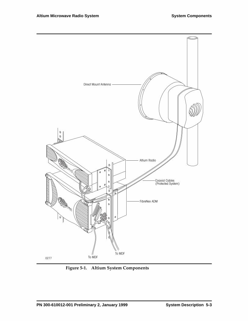
Altium Microwave Radio System System Components
Figure 5-1. Altium System Components
0277
Direct Mount Antenna
Altium Radio
FibreNex ADM
To MDF
Coaxial Cables(Protected System)
To MDF
PN 300-610012-001 Preliminary 2, January 1999 System Description 5-3
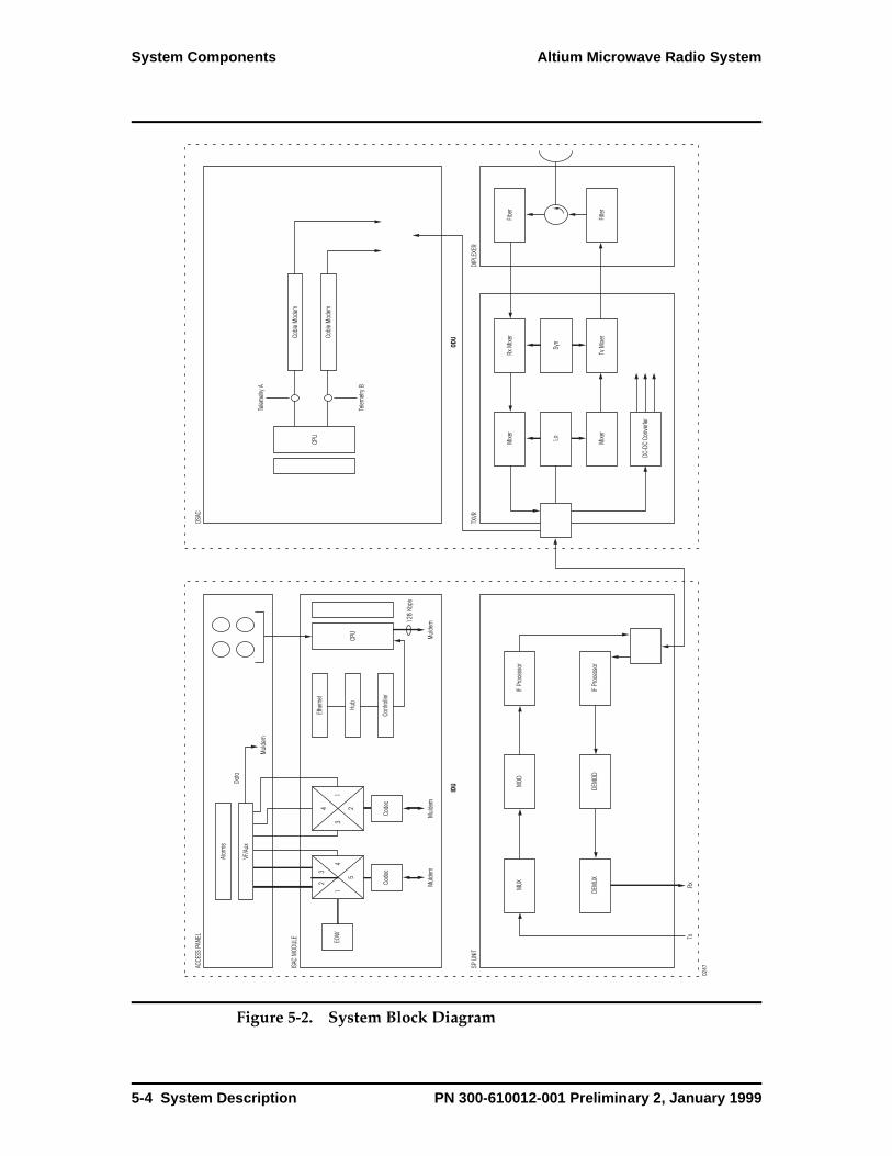
System Components Altium Microwave Radio System
Figure 5-2. System Block Diagram
ACCE
SS P
ANEL
SP U
NIT
IDU
ISAC
MOD
ULE
23
14
5
Alar
ms
Ethe
rnet
Hub
Cont
rolle
r
0247
VF/A
uxDa
ta
Mul
dem
31
24
Code
c
EOW
MUX
TxRx
DEM
UX
MOD
DEM
OD
IF Pr
oces
sor
IF Pr
oces
sor
Code
c
CPU
Mul
dem
Mul
dem
Mul
dem12
8 Kb
ps
OSAC
TXVR
DIPL
EXER
ODUCa
ble
Mod
em
Cabl
e M
odem
Mixe
r
Lo Mixe
r
DC-D
C Co
nver
ter
Rx M
ixer
Syn
Tv M
ixer
Fiber
Filter
CPU
Telem
etry
A
Telem
etry
B
5-4 System Description PN 300-610012-001 Preliminary 2, January 1999
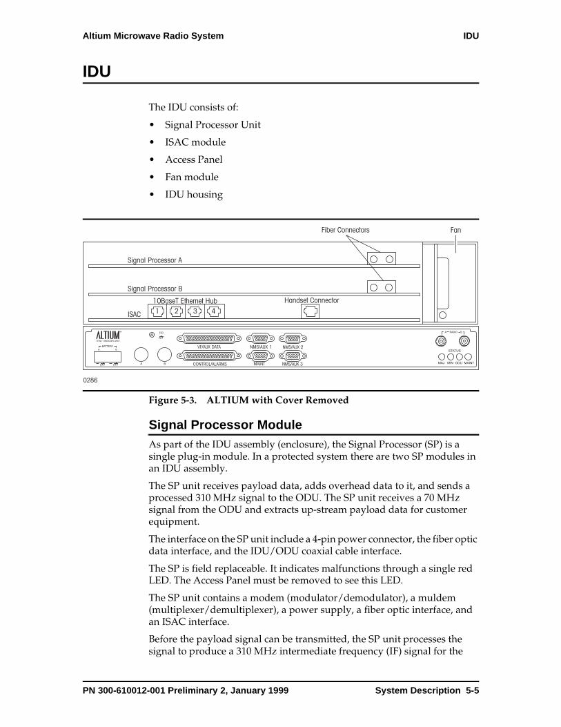
Altium Microwave Radio System IDU
IDU
The IDU consists of:
• Signal Processor Unit
• ISAC module
• Access Panel
• Fan module
• IDU housing
Figure 5-3. ALTIUM with Cover Removed
Signal Processor Module As part of the IDU assembly (enclosure), the Signal Processor (SP) is a single plug-in module. In a protected system there are two SP modules in an IDU assembly.
The SP unit receives payload data, adds overhead data to it, and sends a processed 310 MHz signal to the ODU. The SP unit receives a 70 MHz signal from the ODU and extracts up-stream payload data for customer equipment.
The interface on the SP unit include a 4-pin power connector, the fiber optic data interface, and the IDU/ODU coaxial cable interface.
The SP is field replaceable. It indicates malfunctions through a single red LED. The Access Panel must be removed to see this LED.
The SP unit contains a modem (modulator/demodulator), a muldem (multiplexer/demultiplexer), a power supply, a fiber optic interface, and an ISAC interface.
Before the payload signal can be transmitted, the SP unit processes the signal to produce a 310 MHz intermediate frequency (IF) signal for the
0286
Signal Processor A
Signal Processor B
ISAC
Fiber Connectors Fan
B
A
ESD
VF/AUX DATA
CONTROL/ALARMS
NMS/AUX 1
MAINT
NMS/AUX 2
NMS/AUX 3
STATUS
MAJ MIN ODU MAINT
Handset Connector1 2 3 4
10BaseT Ethernet Hub
PN 300-610012-001 Preliminary 2, January 1999 System Description 5-5

IDU Altium Microwave Radio System
ODU. The SP unit receives the optical input signal and converts it to an electrical signal. The multiplexes overhead data and payload data. Modulates the multiplexed data on a baseband signal. Converts the baseband signal to 310 MHz signal and outputs it to the ODU
In the receive direction, the SP unit processes a 70 MHz from the ODU. The SP unit demodulates the incoming signal (remove the payload data from the modulated radio frequency signal). It then demultiplexes the payload data and overhead data and converts the electrical signal to an optical signal and outputs it to the fiber connector.
ISAC ModuleThe ISAC module is the hardware platform for the operational firmware for the Altium radio. It is a plug-in module located in the bottom slot behind the Access Panel.
The ISAC module provides functions such as maintaining system configurations, collecting status and alarm information from the SP module, and performing protection switching. The ISAC provides access to NMS functions, two auxiliary data channels, and voice channels, through connectors on the Access Panel.
The ISAC module provides the hardware platform for the operational firmware of the Altium radio. The ISAC module:
• Maintains system configuration.
• Collects and displays status and alarm information from the SP and fan modules.
• Maintains two copies of software in FLASH memory.
• Provides analog to digital conversion of analog status signals and temperature sensors.
• Monitors parity and FEC error count.
• Performs radio protection switching.
• Performs maintenance switching and loopbacks.
• Provides the functionality for the DB-9 connectors on the access panel.
• Supports two auxiliary data channels at a nominal 64 Kbps. The actual data rate depends on capacity and configuration. These two data channels can be configured to operate in synchronous or asynchronous mode. The electrical interface for the data channels is TIA/EIA-422 B (V.11).
• Supports two voice frequency (VF) channels. The ISAC uses PCM codecs to convert the VF signals between the ISAC and SP modules.
5-6 System Description PN 300-610012-001 Preliminary 2, January 1999

Altium Microwave Radio System IDU
Access PanelThe Access Panel contains the system status LEDs, power input, fuse holders, connectors for external equipment such as alarms, an anti-static wrist strap, modems, and terminal.
The removable Front Panel provides access to the signal processor unit, ISAC, and fan modules.
Figure 5-4 shows the functionality of the auxiliary (nonpayload) connectors on the Access Panel.
PN 300-610012-001 Preliminary 2, January 1999 System Description 5-7

IDU Altium Microwave Radio System
Figure 5-4. Access Panel Auxiliary (nonpayload) Functions
ISAC68360
uP
SPOverhead Channel
Mux/Demux
Chan1=VF2(82.5 Kb/s)Chan2=CBitsChan3=Aux2(64Kb/s)Chan4=Aux1(64Kb/s)Chan5=Private Chan(64Kb/s)Chan6=NMS2(64Kb/s)Chan7=NMS1(64Kb/s)Chan8=VF1(82.5 Kb/s)
4 Port
Ethernet
Hub
38 Kb/s RS-232 Terminal Interface
56 Kb/s RS-232 Modem Interface
19.2 Kb/s RS-232 Terminal Interface
19.2 Kb/s RS-232 Terminal Interface
WMT Maint. (DCE, DB9F)
NMS/Aux1 (DTE, DB9M)
NMS/Aux2 (DTE, DB9M)
NMS/Aux3 (DTE, DB9M)
10BaseT 1 (MDI-X, RJ-45)
10BaseT 2 (MDI, RJ-45)
10BaseT 3 (MDI, RJ-45)
10BaseT 4 (MDI, RJ-45)
10Mb/s
Private C
han.
NM
S2
64Kb/s RS422/V.11 Async./Sync.
64Kb/s RS422/V.11 Async./Sync.
64KHz RS422/V.11
Tx/Rx Clocks
AUX1 (Data DB37F)
AUX2 (Data DB37F)
VF1
VF2
Handset (RJ-11)
VF1 Bridge Port 1 (Data DB37F)
NM
S1
VF
2
VF
1
Aux2
Aux1
AUX Clks. (Data DB37F)
Speaker (ALM DB37F)
VF1 Bridge Port 2 (Data DB37F)
VF1 Bridge Port 3 (Data DB37F)
VF2 Bridge Port 1 (Data DB37F)
VF2 Bridge Port 2 (Data DB37F)
VF2 Bridge Port 3 (Data DB37F)
4 442
4
4
4
2
4
4
4
4
4
4
4
128 Kb/s
TTL Inputs (Alm, DB37F)
TTL Outputs (Alm, DB37F)
Relay Outputs (Alm, DB37F)
8
4
4
5-8 System Description PN 300-610012-001 Preliminary 2, January 1999
Altium Microwave Radio System IDU
VF/AUX DATA ChannelThe VF/AUX DATA channel provides an interface for two voice frequency (VF) channels and two data channels.
The Altium radio has two separate voice channels that are configured as standard 600 ohm balanced 4-wire telephone interfaces. There are 3 input/output level settings available (via WMT), -16/+7, -3.5/-3.5 and -3.5/-6.5 dBm. Signaling is in-band DTMF, E and M signaling is not supported. These voice channels are converted to a digital format using Codecs. It should be understood that each time that the signal transitions from one link to another this process repeats. This repeated sampling process adds noise to the signal limiting the number of links that can be daisy chained together to about 5 to 10 links. Applications that require a very large number of voice links should consider using an external digital voice orderwire running over the radio’s 64 kb/s Aux Data channel.
PN 300-610012-001 Preliminary 2, January 1999 System Description 5-9

IDU Altium Microwave Radio System
Figure 5-5. VF Channel 1 and 2 Bridges
VF
/Au
x Da
ta D
B3
7F
Co
nn
ecto
r
2-Wire/4-WireHybrid/SLIC
DTMFDecoder
RingerRJ-11
Speaker Out
Handset In/Out *
Voice Ch. 1 Port 1 Input
Voice Ch. 1 Port 1 Output
Voice Ch. 1 Port 2 Input
Voice Ch. 1 Port 2 Output
Voice Ch. 1 Port 3 Input
Voice Ch. 1 Port 3 Output
Voice Ch. 2 Port 1 Input
Voice Ch. 2 Port 1 Output
Voice Ch. 2 Port 2 Input
Voice Ch. 2 Port 2 Output
Voice Ch. 2 Port 3 Input
Voice Ch. 2 Port 3 Output
8 Ohms, 0.5 Watts
1,6
32 T14 R
36 T18 R
27 T 9 R
29 T11 R
31 T13 R
35 T17 R
30 T12 R
34 T16 R
26 T 8 R
28 T10 R
33 T15 R
37 T19 R
15 R 33 T
3 T 4 R
Alarms DB37
Speaker Amp(Vol Cntrl &
The 4-wire 600 ohm balanced voice channel portsoperate at 3 selectable levels:
* The handset does not support the ringer built into the telephone.
1. -3.5 dBm -3.5 dBm
2. -16 dBm +7 dBm
3. -3.5 dBm -6.5 dBm
In Out
Radio Tx
Radio Rx
Radio Tx
Radio Rx
Mute)
1
2
3
4
5
1
2
3
4
ISAC Module4-Port Bridge
5-Port Bridge
5-10 System Description PN 300-610012-001 Preliminary 2, January 1999

Altium Microwave Radio System IDU
Voice Channel 1
Voice channel 1 contains the following orderwire features: a standard RJ-11 2-wire DTMF phone interface (ringer internal to the radio), a 0.5 watt 8 ohm speaker interface (level set via WMT), a 5 port bridge with 3 external 4-wire interfaces (level set via WMT). All three external port levels are changed together. Each terminal has a separate 4 digit DTMF address that will ring its internal buzzer in response to its DTMF code. DTMF calling is implemented via the 2-wire phone on a station to station basis. The three 4-wire bridge ports are used to interconnect other radio links.
PN 300-610012-001 Preliminary 2, January 1999 System Description 5-11
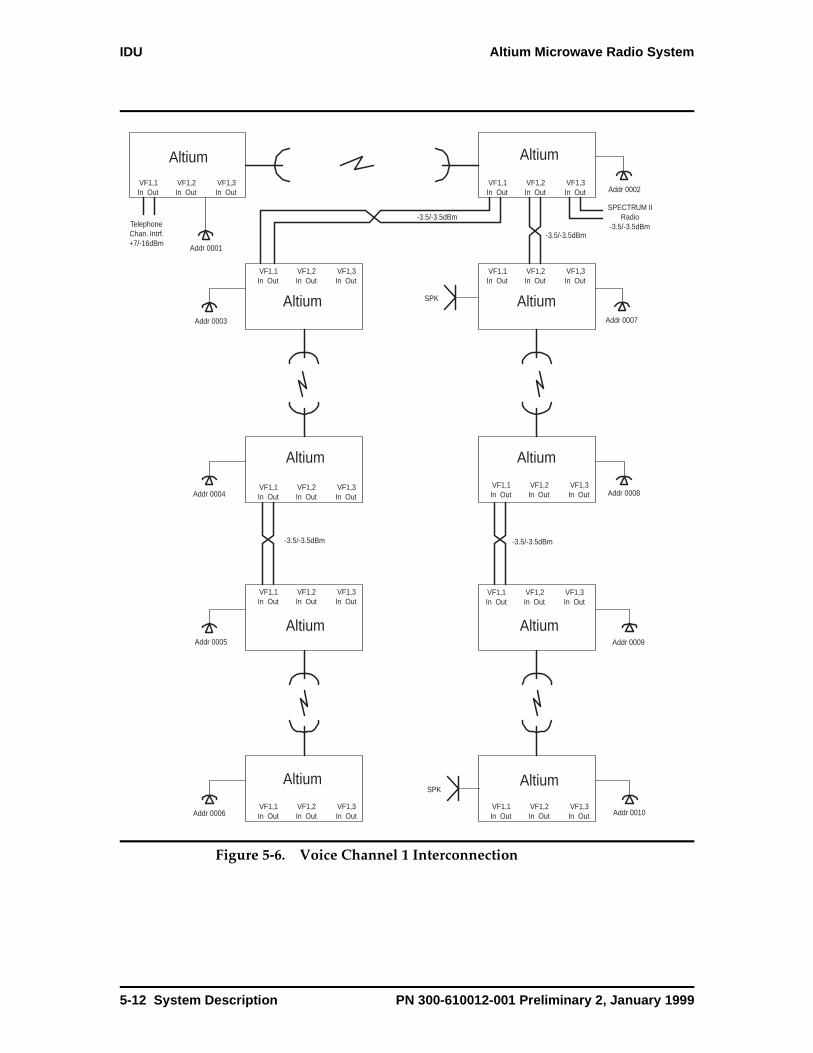
IDU Altium Microwave Radio System
Figure 5-6. Voice Channel 1 Interconnection
Addr 0001
Addr 0002
Addr 0007
Addr 0009
Addr 0010Addr 0006
Addr 0005
Addr 0004
Addr 0003
Addr 0008
TelephoneChan. Intrf.+7/-16dBm
-3.5/-3.5dBm
-3.5/-3.5dBm
-3.5/-3.5dBm-3.5/-3.5dBm
SPECTRUM IIRadio
-3.5/-3.5dBm
VF1,1In Out
VF1,2In Out
VF1,3In Out
VF1,1In Out
VF1,2In Out
VF1,3In Out
VF1,1In Out
VF1,2In Out
VF1,3In Out
VF1,1In Out
VF1,2In Out
VF1,3In Out
VF1,1In Out
VF1,2In Out
VF1,3In Out
VF1,1In Out
VF1,2In Out
VF1,3In Out
VF1,1In Out
VF1,2In Out
VF1,3In Out
VF1,1In Out
VF1,2In Out
VF1,3In Out
VF1,1In Out
VF1,2In Out
VF1,3In Out
VF1,1In Out
VF1,2In Out
VF1,3In Out
Altium
Altium Altium
Altium Altium
Altium Altium
Altium Altium
Altium
SPK
SPK
5-12 System Description PN 300-610012-001 Preliminary 2, January 1999

Altium Microwave Radio System IDU
Voice Channel 2
Voice channel 2 provides minimum features and can be used by an external voice orderwire unit. It has a four port 4-wire bridge with three external interfaces. All ports are set to the same selected level via the WMT. An external orderwire unit must provide signaling and handset interfaces.
Figure 5-7. Voice Channel 2 Interconnection
TelephoneChan. Intrf.+7/-16dBm
-3.5/-3.5dBm
-3.5/-3.5dBm
-3.5/-3.5dBm-3.5/-3.5dBm
VF2,1In Out
VF2,2In Out
VF2,3In Out
Altium
Altium Altium
Altium Altium
Altium Altium
Altium Altium
Altium
ExterExternalnalOrderwireOrderwire
UnitUnit
ExterExternalnalOrderwireOrderwire
UnitUnit
VF2,1In Out
VF2,2In Out
VF2,3In Out
VF2,1In Out
VF2,2In Out
VF2,3In Out
VF2,1In Out
VF2,2In Out
VF2,3In Out
VF2,1In Out
VF2,2In Out
VF2,3In Out
VF2,1In Out
VF2,2In Out
VF2,3In Out
VF2,1In Out
VF2,2In Out
VF2,3In Out
VF2,1In Out
VF2,2In Out
VF2,3In Out
VF2,1In Out
VF2,2In Out
VF2,3In Out
VF2,1In Out
VF2,2In Out
VF2,3In Out
ExterExternalnalOrderwireOrderwire
UnitUnit
ExterExternalnalOrderwireOrderwire
UnitUnit
ExterExternalnalOrderwireOrderwire
UnitUnit
ExterExternalnalOrderwireOrderwire
UnitUnit
PN 300-610012-001 Preliminary 2, January 1999 System Description 5-13
IDU Altium Microwave Radio System
Aux Data ChannelsThere are two RS-422/V.11 Aux data channels that operate either synchronously or asynchronously. One channel may be synchronous while the other is asynchronous or both channel may be configured the same.
The AUX channel provides two 64 Kbps RS422 data channels with a common clock. Each channel can be configured as 64 kbps synchronous data channel or oversampled 19.2 kbps asynchronous data channel. The data channel type and rate is configured by the user through the WMT (Aux Data Channel Screen on page 4-38). The selection of an internal or external 64 Kbps clock is also configurable through the WMT. If a radio is configured to operate with an external clock and loses that clock, the radio switches to an internal clock and generates a minor alarm.
Synchronous Aux Data Channel OperationThe synchronous mode operates at 64Kb/s ± 100 ppm. A common transmit and a common receive clock serve both synchronous channels. The transmit (input) clock can be supplied by the radio equipment or provided externally. The receive (output) clock is supplied by the radio and is synchronous to the remote terminals transmit clock input. Both transmit and receive clock edges are user selected based on the rising edge or falling edge being coincident with the center of data interval. There are two clock conditions to consider.
The external transmit (input) clock edge is chosen depending on the orientation of the data and clock as viewed on an oscilloscope at the transmit input of the radio. If the orientation of the clock and data signals correspond to the rising edge clock coincident with the center of the data interval, then the rising edge should be selected for the transmit clock via the WMT. Likewise, if the clock and data appear oriented with the falling edge waveform in the center of data interval, then the falling edge clock option should be chosen via the WMT. The same relationship applies when the internal transmit (output) clock is chosen.
The receive (output) clock orientation must be chosen by knowing the required clock orientation of the external equipment input. The clock should be placed such that external equipment samples the data in middle of the data interval not on the transition. Again, the receive output clock orientation can be selected via the WMT as rising or falling edge oriented as shown below.
5-14 System Description PN 300-610012-001 Preliminary 2, January 1999

Altium Microwave Radio System IDU
Tx or Rx Data
Tx or Rx Clock (rising edge)
Tx or Rx Clock (falling edge)
Typical applications for the synchronous channel include a digital channel multiplexer such as a Newbridge 3600, Cisco routers or bridges and data access devices or other channel bank equipment with DS-0 64 kb/s RS-422/V.11 interfaces. These channels could be used to provide a low rate synchronous data network using protocols such as X.25 or HDLC.
Rising Edge
Falling Edge
PN 300-610012-001 Preliminary 2, January 1999 System Description 5-15
IDU Altium Microwave Radio System
Asynchronous Aux Data Channel OperationThe asynchronous channel operates in two modes: non-data dependent over-sampled or a UART type data dependent mode that supports 5 specific data rates and 7 character formats.
Asynchronous Non-Data Dependent Mode
The non-data dependent mode is limited to a maximum rate of 19.2 kbs and is over-sampled by an internal 64 kHz clock. There is a limit as to how many links may be interconnected due to the jitter accumulation caused by the over-sampling process. The lower the data rate the more links that may be crossed. As an example: operating at 19.2 kbs will only cross one link error free. Multi-link asynchronous data systems should utilize the data dependent mode.
Asynchronous Data Dependent Mode
The data dependent mode operates with 5 data rates (1200, 2400, 4800, 9600 & 19.2 kbs) and various combinations of data, stop and parity bits (6,2,1 or 7,2,0 or 7,1,1 or 7,2,1 or 8,1,0 or 8,2,0 or 8,1,1). The data is also over-sampled by an internal 64 kHz clock, but the internal circuits operate similar to a UART allowing the data to be passed over an unlimited number of links without jitter accumulation. The data rate and character type selected must be the same as the incoming data or the channel will not process the characters correctly.
Asynchronous Data Channel ApplicationsApplications include any asynchronous RS-422/V.11 device interfaces, such as a modem or data terminal. It could be used to connect to a SPECTRUM II radio systems network management terminal at one end and a string of SPECTRUM II radio links at a downstream location. Other applications include remote data collection, monitoring and control functions.
5-16 System Description PN 300-610012-001 Preliminary 2, January 1999
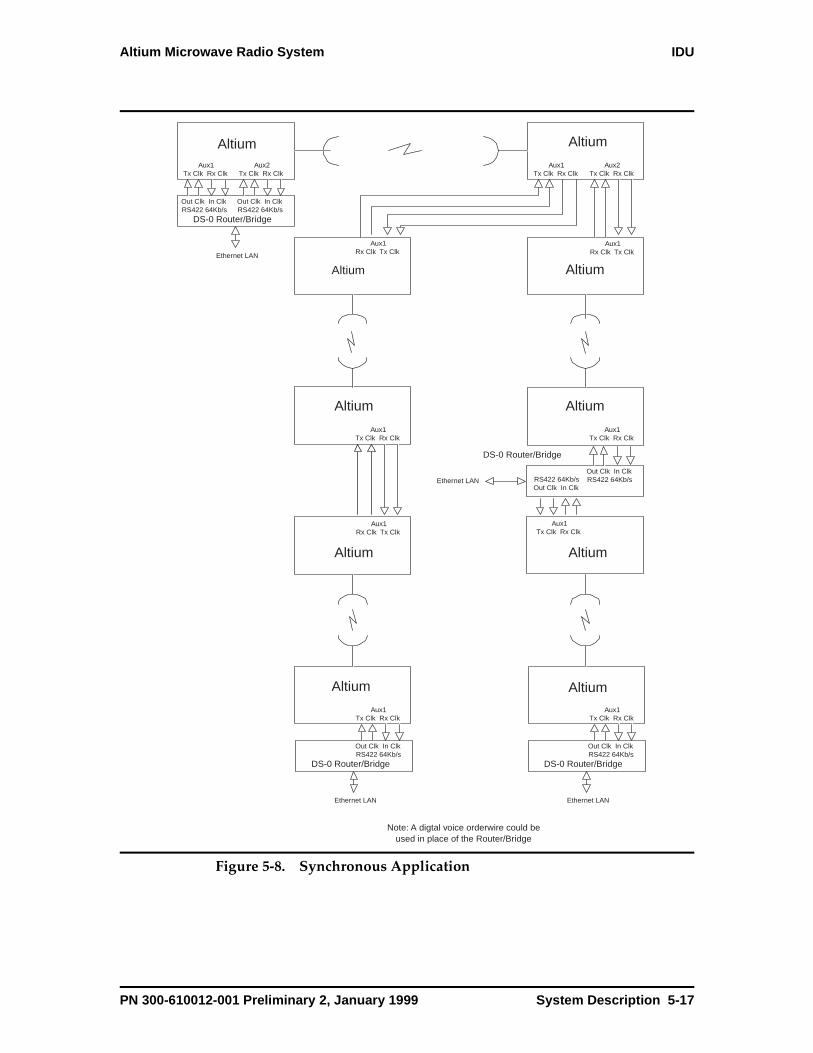
Altium Microwave Radio System IDU
Figure 5-8. Synchronous Application
Altium
Altium Altium
Altium Altium
Altium Altium
Altium Altium
Altium
Out Clk In ClkRS422 64Kb/s
DS-0 Router/Bridge
Out Clk In ClkRS422 64Kb/s
Ethernet LAN
Aux1Tx Clk Rx Clk
Aux2Tx Clk Rx Clk
Aux1Tx Clk Rx Clk
Aux2Tx Clk Rx Clk
Aux1Rx Clk Tx Clk
Aux1Rx Clk Tx Clk
Aux1Tx Clk Rx Clk
Aux1Tx Clk Rx Clk
Aux1Tx Clk Rx Clk
Aux1Tx Clk Rx Clk
Aux1Tx Clk Rx Clk
Aux1Rx Clk Tx Clk
DS-0 Router/Bridge
Out Clk In ClkRS422 64Kb/s
Ethernet LAN
DS-0 Router/Bridge
Out Clk In ClkRS422 64Kb/s
Ethernet LAN
RS422 64Kb/sOut Clk In Clk
DS-0 Router/Bridge
Out Clk In ClkRS422 64Kb/sEthernet LAN
Note: A digtal voice orderwire could beused in place of the Router/Bridge
PN 300-610012-001 Preliminary 2, January 1999 System Description 5-17
IDU Altium Microwave Radio System
CONTROL/ALARMS ConnectorThe CONTROL/ALARMS connector provides eight TTL inputs, four TTL outputs, and four relays (Figure 5-9 and Figure 5-10).
TTL Inputs
Eight TTL level compatible status inputs are available. Their change of state is logged in the radio event log that is viewable by the NMS or WMT as TTL external input 1,2…..8 events. The active state is a TTL high (+5 volts) while the normal state is a TTL low (0 volts). If the input is left open pull-up resistors set the state high (+5 volts). The inputs can also be designated as unused and as such they will not create any log entries.
Typical applications for the TTL inputs might be to monitor site access alarms or other communications device alarms.
TTL Outputs
There are 4 TTL outputs that can be set high (+5 volts) or low (0 volts) by the user via the NMS or WMT configuration menu. Their change in state is reported in the event log as TTL external output 1,2,3 or 4 events.
Typical applications for the TTL outputs include controlling site lighting or other externally controlled devices.
5-18 System Description PN 300-610012-001 Preliminary 2, January 1999
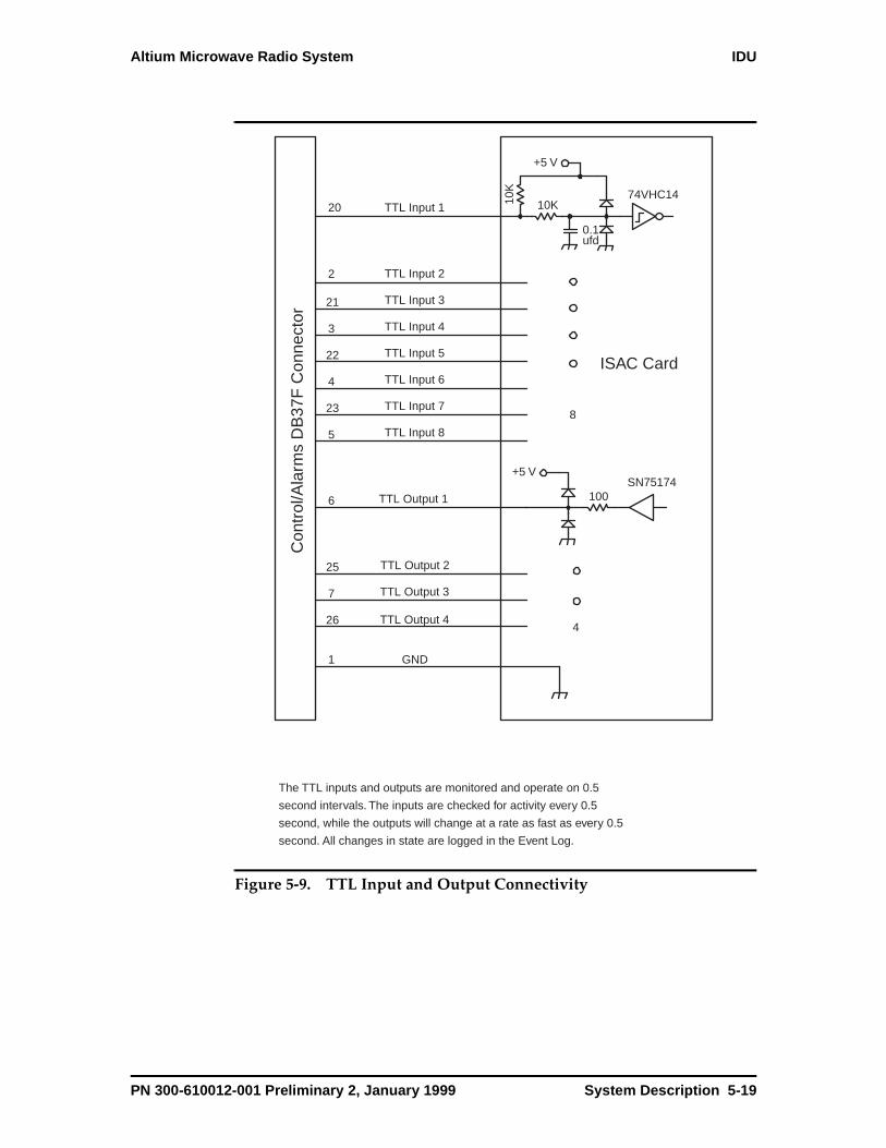
Altium Microwave Radio System IDU
Figure 5-9. TTL Input and Output Connectivity
ISAC Card
Con
trol
/Ala
rms
DB
37F
Con
nect
or
20
2
21
3
22
4
5
23
6
26
25
7
The TTL inputs and outputs are monitored and operate on 0.5
second intervals. The inputs are checked for activity every 0.5
second, while the outputs will change at a rate as fast as every 0.5
second. All changes in state are logged in the Event Log.
0.1ufd
10K
+5 V
74VHC14
100
+5 VSN75174
8
1
4
GND
TTL Output 4
TTL Output 3
TTL Output 2
TTL Output 1
TTL Input 8
TTL Input 7
TTL Input 6
TTL Input 5
TTL Input 4
TTL Input 3
TTL Input 2
TTL Input 1
10K
PN 300-610012-001 Preliminary 2, January 1999 System Description 5-19
IDU Altium Microwave Radio System
Relays
There are 4 form “C” relays available for alarm and control outputs. Two of the relays are non-latching and two are latching (remain in the last state when power is removed). Two alarm indications may be assigned to the non-latching relays, Minor and Major. The alarm is active when the relay is de-energized i.e. normally closed terminal (N.C.) is in contact with the common terminal (C). This is done so that the alarms will show active if the radio losses power.
The user may also set the relays in a manual mode via the NMS or WMT. A forced open condition will open the connection between the normally closed and common terminals. A forced closed condition will connect the normally closed and common terminals.
5-20 System Description PN 300-610012-001 Preliminary 2, January 1999

Altium Microwave Radio System IDU
Figure 5-10. Relays Connectivity
ISAC Module
N.O.
N.C.COM
N.O.
N.C.COM
N.O.
N.C.COM
N.O.
N.C.COM
Relay 1(Unlatched)
Relay 2(Unlatched)
Relay 3(Latched)
Relay 4(Latched)
Relays shown in de-energized manualopen position. Maximum resistiveswitching load 0.5A at 30 VDC.
Ala
rm D
B3
7F
Co
nn
ecto
r
8
9
27
28
29
10
11
12
30
31
32
13
The relays operate in 3 modes via the WMT, NMS or Major/Minoralarms. Their change of state is also reported in the event log.
1. Manual Mode allows you to name and operate the selected relay. the two states are: Manual Open (N.O. contact open) Manual Closed (N.O. contact closed)
2. Terminal Alarm Mode allows you to select Major and Minor alarms to control the relays. This mode is for relays 1 and 2 only. The two states are: Major, Minor active (N.O. contact closed, energized) Major, Minor inactive (N.O. contact open, de-energized)
3. With the Unused Mode there is no event reporting and relays remain in a de-energized (N.O. contact open) state. Same as Manual Open.
PN 300-610012-001 Preliminary 2, January 1999 System Description 5-21

IDU Altium Microwave Radio System
Handset ConnectorThe engineering orderwire (EOW) handset interface is an RJ-11, six-wire modular jack located on the ISAC. The handset connector provides an interface to EOW (engineering orderwire) functionality. That is, voice communication on an overhead channel using a standard 2-wire handset and DTMF (dual tone multi-frequency) dialing. The speaker on the ISAC provides the ringer; however, there is no ringback. Through the VF channel 1 5-port bridge, several radios in a network can receive the EOW signal. Even though each radio can be assigned a different EOW address, the EOW functions as a party line. Refer to VF/AUX DATA Channel on page 5-9.
Ethernet HubFour RJ-45 connectors provide 10 Base-T Ethernet access. The Ethernet data rate is 10 Mbps on the bridge ports and 128 Kbps across the link. The connector on the first port (Connector 1) provides a Media Dependent Interface (MDI-X), a standard interface for unshielded twisted pair (UTP) cable. MDI-X provides the crossover function that is necessary when chaining Ethernet hubs together. The connectors for ports 2, 3, and 4 are wired as an MDI interface. The pinout functions are opposite that of port 1. The MDI-X interface allows you to use a straight-through cable to chain Ethernet hubs together: you connect an MDI-X port to an MDI port. To use a crossover cable, connect an MDI-X port to an MDI-X port or connect an MDI port to an MDI port.
When daisychaining Altium systems together through the Ethernet hub, remember that:
• Maximum cable length including drop leads is 100 meters
• Each cable provides a point-to-point connection
• Each cable is a single segment
• The cable must be between 85 ohms and 110 ohms
• The cable are terminated with RJ-45 connectors
Fan ModuleThe fan module consists of two fans mounted on a single plug-in card. A module fail LED indicates that a fan has failed.
IDU HousingEncloses the signal processor, ISAC, and fan modules. These modules plug in to the IDU housing backplane. The IDU motherboard, not a replaceable module, provides additional circuit-board trace-routing capacity for the plug-in modules.
5-22 System Description PN 300-610012-001 Preliminary 2, January 1999
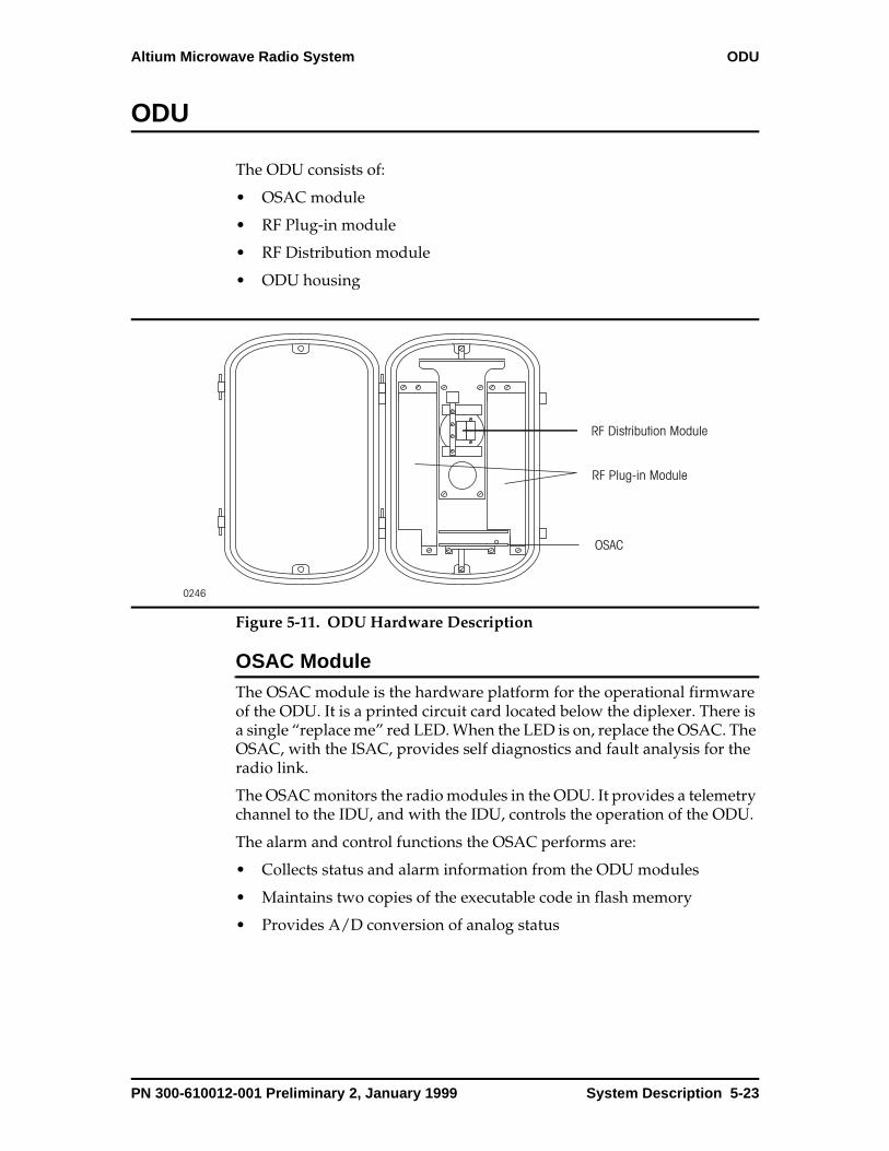
Altium Microwave Radio System ODU
ODU
The ODU consists of:
• OSAC module
• RF Plug-in module
• RF Distribution module
• ODU housing
Figure 5-11. ODU Hardware Description
OSAC ModuleThe OSAC module is the hardware platform for the operational firmware of the ODU. It is a printed circuit card located below the diplexer. There is a single “replace me” red LED. When the LED is on, replace the OSAC. The OSAC, with the ISAC, provides self diagnostics and fault analysis for the radio link.
The OSAC monitors the radio modules in the ODU. It provides a telemetry channel to the IDU, and with the IDU, controls the operation of the ODU.
The alarm and control functions the OSAC performs are:
• Collects status and alarm information from the ODU modules
• Maintains two copies of the executable code in flash memory
• Provides A/D conversion of analog status
0246
RF Distribution Module
RF Plug-in Module
OSAC
PN 300-610012-001 Preliminary 2, January 1999 System Description 5-23
ODU Altium Microwave Radio System
RF Plug-in ModuleThe RF Plug-in module consists of the RF transceiver assembly and the IF assembly. In a protected system there are two transceiver assemblies located to the left and right of the diplexer. Together with the synthesizer oscillator, the RF Plug-in module performs the dual upconversion and dual downconversion function.
The RF transceiver assembly contains a transmit and receive section. The input TX signal is at a fixed frequency of 2158 MHz. It is upconverted to the desired TX RF frequency using a low side LO signal from the synthesizer module. The upconverted signal is then amplified to the proper output power level. The input signal is sent from the IF assembly and the output signal is sent to the RF distribution.
The input RX signal is downconverted to a fixed frequency of 1778 MHz using a low side LO signal from the synthesizer module. The input signal is sent from the RF distribution and the output signal is sent to the IF assembly.
The IF assembly also contains a transmit and receive section. The 310 MHz TX signal is filtered from the interface cable signals. The signal is upconverted to 2158 MHz using the shared IF LO of 1848 MHz. The output 2158 MHz TX signal is sent to the RF TXVR assembly.
The input 1738 MHz RX signal is sent from the RF transceiver assembly. This signal is downconverted to 70 MHz using the shared IF LO of 1848 MHz.
The IF assembly also contains the DC-DC converter to supply voltages to the ODU (including the synthesizer module and the OSAC).
RF Distribution ModuleThe RF distribution module provides isolation between the transmitted signal and the received signal through filters and circulators. This allows better flexibility for transmit/receive spacing. The transmit filter rejects noise generated by the transmit chain. The receive filter rejects any out-of-band signal, which can interfere with the received signal.
The RF Distribution module separates the transmitted signals from the received signals. The RF Distribution module is located in the middle of the ODU housing and connects to the antenna either directly or through a waveguide.
The ODU converts data from the IDU into an RF signal for transmission, and it converts the RF signal from the far end to data suitable to send to the IDU.
The transmit baseband from the IDU first passes through the CPU/Power Supply module where the data signal is separated from the other signals (telemetry, etc.) on the cable. The transceiver directly mixes the modulated signal with the transmit frequency of the radio, amplifies the signal and sends it to the antenna for transmission to the far-end terminal. The
5-24 System Description PN 300-610012-001 Preliminary 2, January 1999
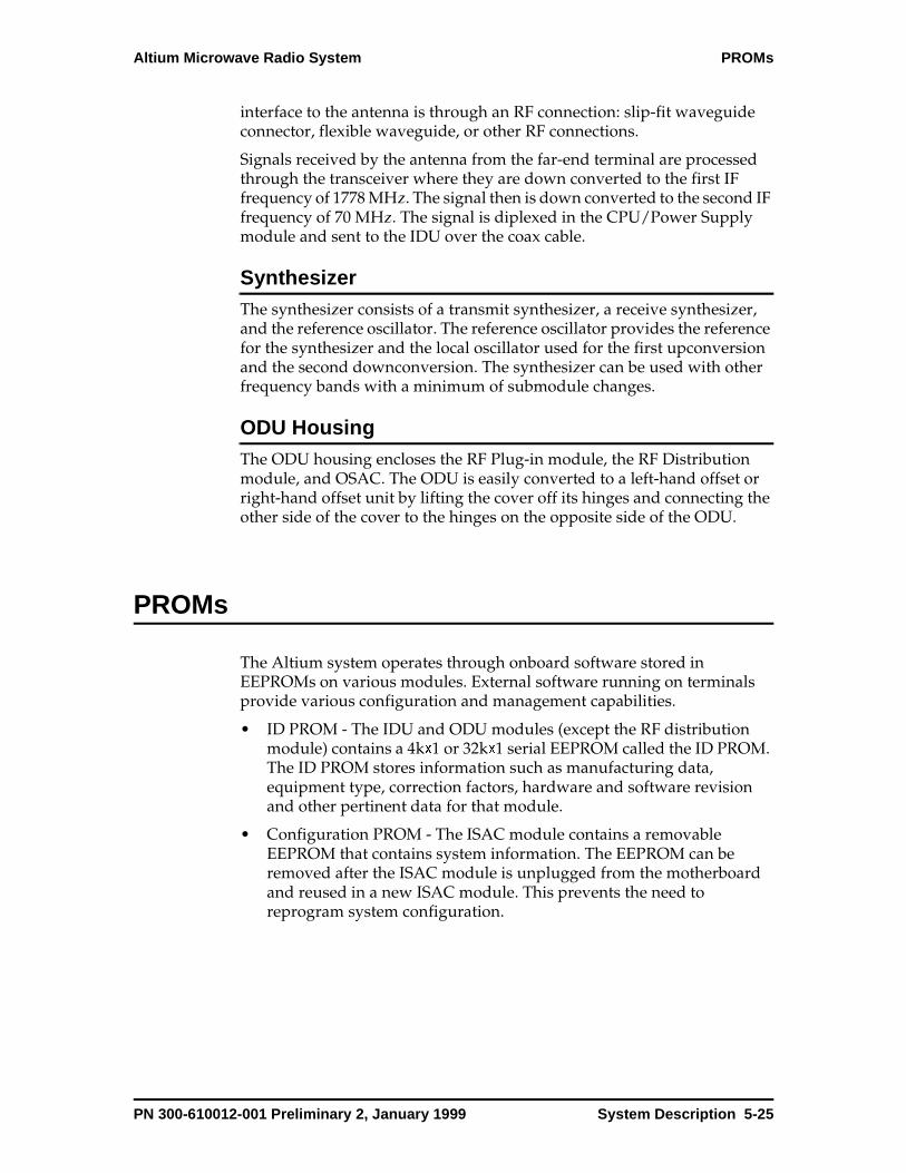
Altium Microwave Radio System PROMs
interface to the antenna is through an RF connection: slip-fit waveguide connector, flexible waveguide, or other RF connections.
Signals received by the antenna from the far-end terminal are processed through the transceiver where they are down converted to the first IF frequency of 1778 MHz. The signal then is down converted to the second IF frequency of 70 MHz. The signal is diplexed in the CPU/Power Supply module and sent to the IDU over the coax cable.
SynthesizerThe synthesizer consists of a transmit synthesizer, a receive synthesizer, and the reference oscillator. The reference oscillator provides the reference for the synthesizer and the local oscillator used for the first upconversion and the second downconversion. The synthesizer can be used with other frequency bands with a minimum of submodule changes.
ODU HousingThe ODU housing encloses the RF Plug-in module, the RF Distribution module, and OSAC. The ODU is easily converted to a left-hand offset or right-hand offset unit by lifting the cover off its hinges and connecting the other side of the cover to the hinges on the opposite side of the ODU.
PROMs
The Altium system operates through onboard software stored in EEPROMs on various modules. External software running on terminals provide various configuration and management capabilities.
• ID PROM - The IDU and ODU modules (except the RF distribution module) contains a 4kx1 or 32kx1 serial EEPROM called the ID PROM. The ID PROM stores information such as manufacturing data, equipment type, correction factors, hardware and software revision and other pertinent data for that module.
• Configuration PROM - The ISAC module contains a removable EEPROM that contains system information. The EEPROM can be removed after the ISAC module is unplugged from the motherboard and reused in a new ISAC module. This prevents the need to reprogram system configuration.
PN 300-610012-001 Preliminary 2, January 1999 System Description 5-25

Connectors Altium Microwave Radio System
S3,
ls.
h
Connectors
Table 5-1. Connector Summary
Connector Location Description
Power Access Panel The battery supply connects to the Altium system through a two-conductor Phoenix connector.
ESD Access Panel An anti-static wrist strap plugs into the ESD connector.
IDU/ODU Interface Access Panel A 75-ohm coaxial cable connects the IDU to the ODU.
NMS/Aux 1 Access Panel A DB-9 connector
NMS/Aux2, NMS/Aux 3 Access Panel A DB-9 connector
Maint Access Panel A DB-9 connector
Tributaries Access Panel Interface for nonoptical payload data (E1, E3, DS1, Detc.).
VF/AUX Access Panel 37-pin connector that provides an interface for 2 voice channels and 2 synchronous/asynchronous data channe
Alarms Access Panel 37-pin connector that provides an alarm interface whiccan control 4 relays, 8 alarms,
Ethernet ISAC module A 4-port hub providing
Handset ISAC module An RJ-11 connector for the orderwire handset.
Motherboard ISAC module Two ribbon cable connectors
IF SP Unit SMB connector
Fiber Interface SP Unit Two connectors
5-26 System Description PN 300-610012-001 Preliminary 2, January 1999

Altium Microwave Radio System LEDs
LEDs
LEDs provide operational status and module fail information. They are controlled by the ISAC and the OSAC. The LEDs on the Access Panel are listed in Table 5-2.
The IDU contains the ISAC module and SP unit.
Table 5-2. LED Alarm Indications
Alarm Description
Major Red. Indicates traffic-affecting fault.
Minor Yellow. Indicates nontraffic affecting fault.
ODU Red - Indicates traffic-affecting fault.Yellow - Indicates nontraffic affecting fault and fault is in the path or ODU.
Maintenance Green - On indicates normal operating modeGreen - Flashing indicates self test. Yellow - On indicates protection has been manually switched. Yellow - Flashing indicates local and remote loopback testing in progress.
PN 300-610012-001 Preliminary 2, January 1999 System Description 5-27
Coaxial Cable Altium Microwave Radio System
Coaxial Cable
The coaxial cable connects the IDU to the ODU. In a protected system there are two coaxial cables. For more information on coaxial cables, see Installing the IDU/ODU Coaxial Cable on page 1-22
Antenna
The antenna is application specific. It contains hardware for direct or remote mounting. For more information on the antenna, refer to the manufacturer’s documentation.
Web Maintenance Terminal
The Web Maintenance Terminal (WMT) application consists of a web browser running on a service terminal and WMT software on the Altium radio. The WMT software on the Altium radio is installed during the manufacturing process. It can be reloaded or upgraded in the field through the WMT. You can connect the maintenance terminal to the Altium radio either directly or remotely.
5-28 System Description PN 300-610012-001 Preliminary 2, January 1999
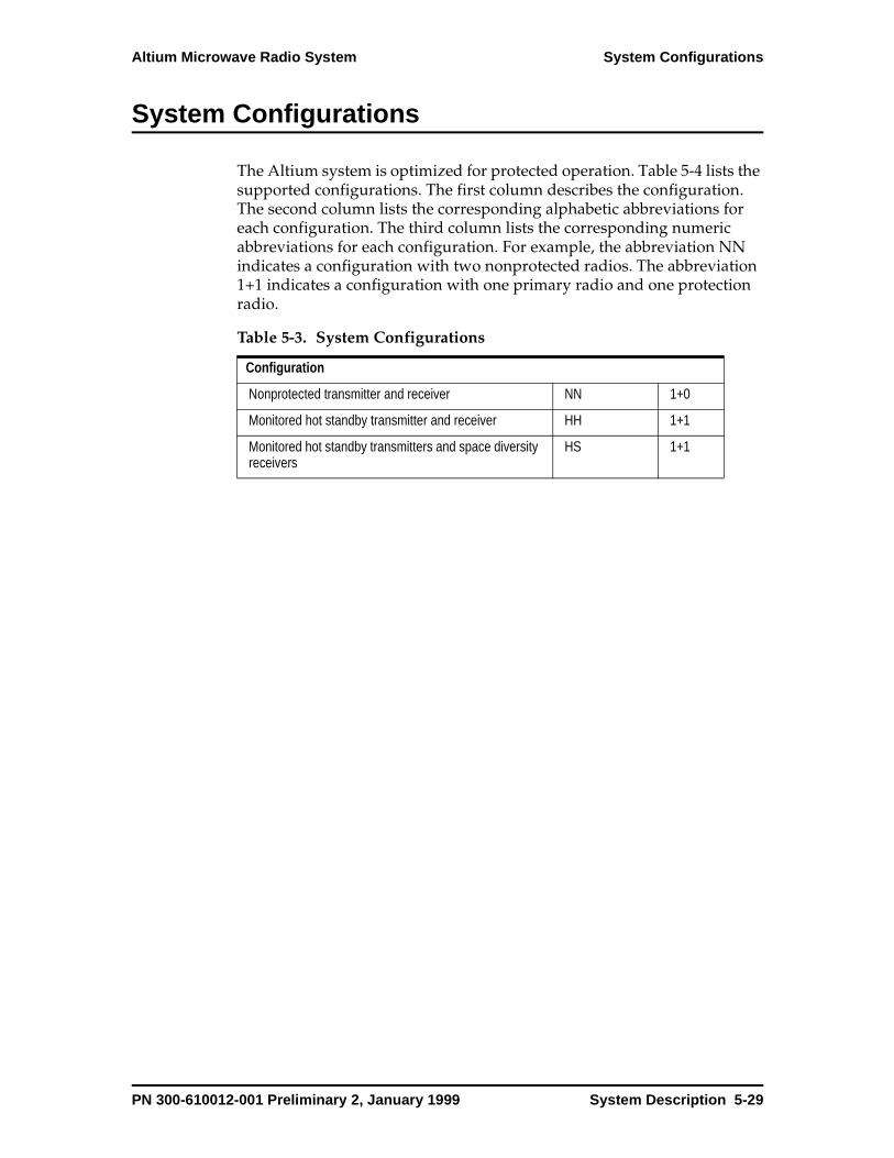
Altium Microwave Radio System System Configurations
System Configurations
The Altium system is optimized for protected operation. Table 5-4 lists the supported configurations. The first column describes the configuration. The second column lists the corresponding alphabetic abbreviations for each configuration. The third column lists the corresponding numeric abbreviations for each configuration. For example, the abbreviation NN indicates a configuration with two nonprotected radios. The abbreviation 1+1 indicates a configuration with one primary radio and one protection radio.
Table 5-3. System Configurations
Configuration
Nonprotected transmitter and receiver NN 1+0
Monitored hot standby transmitter and receiver HH 1+1
Monitored hot standby transmitters and space diversity receivers
HS 1+1
PN 300-610012-001 Preliminary 2, January 1999 System Description 5-29

Protection Switching Altium Microwave Radio System
Protection Switching
Protection switching detects circuitry malfunctions on the SP unit and routes data to provide maximum protection against failures and to isolate internal or external system faults.
There are two types of protection switching: on-demand (manual) and automatic. Additionally, automatic remote TX switching protects the receiver from silent TX remote failures.
Figure 5-12. Nonprotected Altium Configuration
Table 5-4. Protected System Configurations
Configuration
Nonprotected transmitter and receiver 1+0
Monitored hot standby transmitter and receiver 1+1
Monitored hot standby transmitters and space diversity receivers
1+1
Signal Processor AISAC
MAJ MIN ODU MAINT
STATUS
A RADIO B
ESDSTM-1 INDOOR UNIT
VF/AUX DATA
ALARMS
NMS/AUX 3
MAINT
NMS/AUX 1
NMS/AUX 2
A
A
B
BBATTERY
1
0
1
0
0184
DiplexerRF Unit
5-30 System Description PN 300-610012-001 Preliminary 2, January 1999
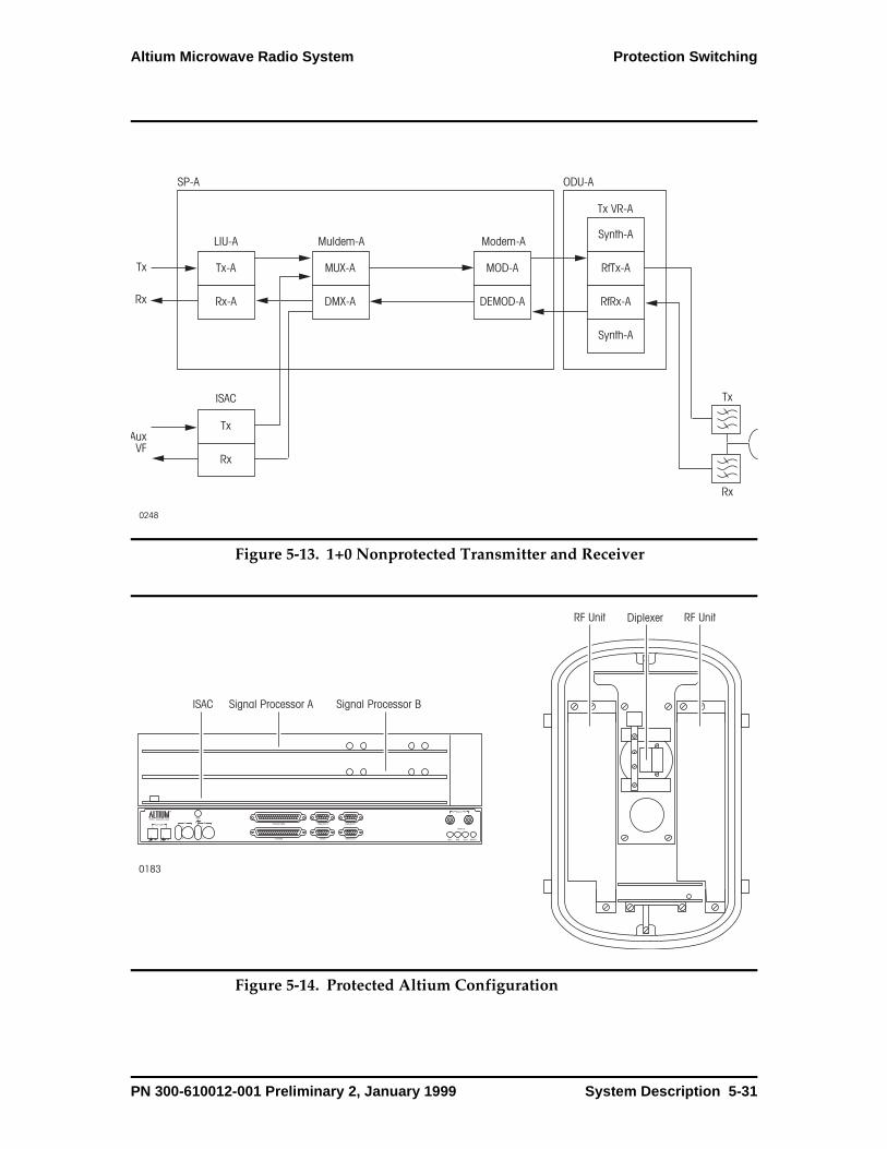
Altium Microwave Radio System Protection Switching
Figure 5-13. 1+0 Nonprotected Transmitter and Receiver
Figure 5-14. Protected Altium Configuration
Tx
AuxVF
Rx
Tx-A
LIU-A
SP-A
ISAC
Muldem-A
Rx-A
MUX-A
DMX-A
Modem-A
Tx VR-A
MOD-A
DEMOD-A
RfTx-A
Synth-A
RfRx-A
Synth-A
Tx
Rx
Tx
Rx
ODU-A
0248
Signal Processor A Signal Processor BISAC
0183
DiplexerRF Unit RF Unit
PN 300-610012-001 Preliminary 2, January 1999 System Description 5-31

Protection Switching Altium Microwave Radio System
Figure 5-15. 1+1 Monitored Hot Standby Protection Switching
Tx
0182
AuxVF
Rx
Tx-A
LIU-A
SP-A
ISAC
Muldem-A
Rx-A
MUX-A
DMX-A
Modem-A
Tx VR-A
MOD-A
DEMOD-A
RfTx-A
Synth-A
RfRx-A
Synth-A
Tx
Rx
Tx
Rx
Tx
Rx
Tx-B
LIU-B
SP-B
ODU-A
ODU-B
Muldem-B
Rx-B
MUX-B
DMX-B
Modem-B
Tx VR-B
MOD-B
DEMOD-B
RfTx-B
Synth-B
RfRx-B
Synth-B
5-32 System Description PN 300-610012-001 Preliminary 2, January 1999
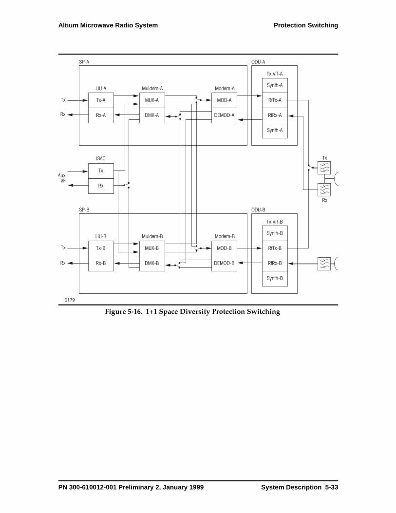
Altium Microwave Radio System Protection Switching
Figure 5-16. 1+1 Space Diversity Protection Switching
Tx
0179
AuxVF
Rx
Tx-A
LIU-A
SP-A
ISAC
Muldem-A
Rx-A
MUX-A
DMX-A
Modem-A
Tx VR-A
MOD-A
DEMOD-A
RfTx-A
Synth-A
RfRx-A
Synth-A
Tx
Rx
Tx
Rx
Tx
Rx
Tx-B
LIU-B
SP-B
ODU-A
ODU-B
Muldem-B
Rx-B
MUX-B
DMX-B
Modem-B
Tx VR-B
MOD-B
DEMOD-B
RfTx-B
Synth-B
RfRx-B
Synth-B
PN 300-610012-001 Preliminary 2, January 1999 System Description 5-33
Automatic Transmit Power Control Altium Microwave Radio System
Automatic Transmit Power Control
Automatic transmit power control (ATPC) provides two transmit power levels. Normal operation is at a low output power level. During certain conditions, the Altium system switches to a higher transmit power level (increase by 7 dB or more, depending on the transmit power output attenuation setting). ATPC switches back to the low transmit power level when external conditions permit it or when a time threshold is reached. ATPC causes no interruption in traffic.
The receiver determines the need to increase transmit power depending on low RSL, FEC, and parity counter overflow alarms. ATPC can be active for 5 minutes at a time. After that, it must be deactivated and an alarm raised.
5-34 System Description PN 300-610012-001 Preliminary 2, January 1999
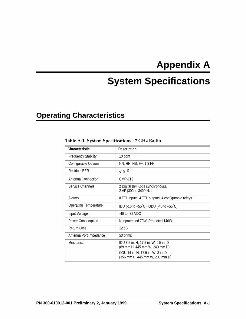
Appendix A
System S pecifications
Operating Characteristics
Table A-1. System Specifications - 7 GHz Radio
Characteristic Description
Frequency Stability 10 ppm
Configurable Options NN, HH, HS, FF, 1:3 FF
Residual BER <10 -13
Antenna Connection CMR-112
Service Channels 2 Digital (64 Kbps synchronous), 2 VF (300 to 3400 Hz)
Alarms 8 TTL inputs, 4 TTL outputs, 4 configurable relays
Operating Temperature IDU (-10 to +55°C), ODU (-45 to +55°C)
Input Voltage -40 to -72 VDC
Power Consumption Nonprotected 70W, Protected 140W
Return Loss 12 dB
Antenna Port Impedance 50 ohms
Mechanics IDU 3.5 in. H, 17.5 in. W, 9.5 in. D(89 mm H, 445 mm W, 240 mm D)ODU 14 in. H, 17.5 in. W, 8 in. D(356 mm H, 445 mm W, 200 mm D)
PN 300-610012-001 Preliminary 2, January 1999 System Specifications A-1
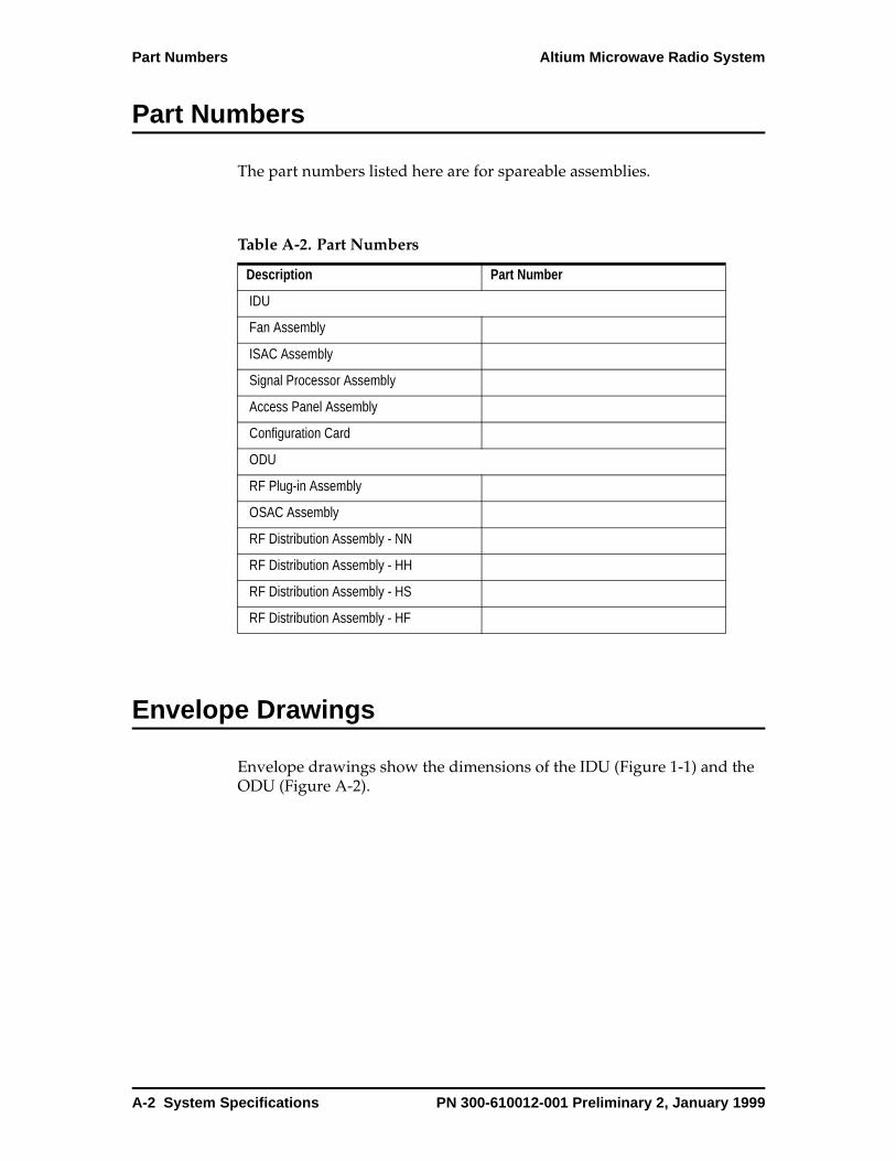
Part Numbers Altium Microwave Radio System
Part Numbers
The part numbers listed here are for spareable assemblies.
Envelope Drawings
Envelope drawings show the dimensions of the IDU (Figure 1-1) and the ODU (Figure A-2).
Table A-2. Part Numbers
Description Part Number
IDU
Fan Assembly
ISAC Assembly
Signal Processor Assembly
Access Panel Assembly
Configuration Card
ODU
RF Plug-in Assembly
OSAC Assembly
RF Distribution Assembly - NN
RF Distribution Assembly - HH
RF Distribution Assembly - HS
RF Distribution Assembly - HF
A-2 System Specifications PN 300-610012-001 Preliminary 2, January 1999

Altium Microwave Radio System Envelope Drawings
Figure 1-1. IDU Envelope Drawing
0249
10.984
5.220
19.142
16.850
5.220
B
ANMS/AUX1 NMS/AUX1
NMS/AUX2MAINT
ESD
PN 300-610012-001 Preliminary 2, January 1999 System Specifications A-3

Envelope Drawings Altium Microwave Radio System
Figure A-2. ODU Envelope Drawing
12.427
9.365
19.142
0201
Bottom
Side
Front (open)
A-4 System Specifications PN 300-610012-001 Preliminary 2, January 1999
Glossar y
100BaseT. 100-Mbps baseband Fast Ethernet specification using UTP wiring. Like the 10BaseT technology on which it is based, 100BaseT sends link pulses over the network segment when no traffic is present. However, these link pulses contain more information than those used in 10BaseT. Based on the IEEE 802.3 standard. See also 10BaseT, Fast Ethernet, and IEEE 802.3.
10Base2. 10-Mbps baseband Ethernet specification using 50-ohm thin coaxial cable. 10Base2, which is part of the IEEE 802.3 specification, has a distance limit of 606.8 feet (185 meters) per segment. See also Cheapernet, Ethernet, IEEE 802.3, and Thinnet.
10BaseT. 10-Mbps baseband Ethernet specification using two pairs of twisted-pair cabling (Category 3, 4, or 5): one pair for transmitting data and the other for receiving data. 10BaseT, which is part of the IEEE 802.3 specification, has a distance limit of approximately 328 feet (100 meters) per segment. See also Ethernet and IEEE 802.3.
802.12. IEEE LAN standard that specifies the physical layer and the MAC sublayer of the data link layer. IEEE 802.12 uses the demand priority media-access scheme at 100 Mbps over a variety of physical media.
802.x. Set of IEEE standards for the definition of LAN protocols.
A&B bit signaling. Procedure used in T1 transmission facilities in which each of the 24 T1 subchannels devotes one bit of every sixth frame to the carrying of supervisory signaling information. Also called 24th
channel signaling.
address. Data structure or logical convention used to identify a unique entity, such as a particular process or network device.
ADC or A/D. Analog to Digital Converter
address mapping. Technique that allows different protocols to interoperate by translating addresses from one format to another. For example, when routing IP over X.25, the IP addresses must be mapped to the X.25 addresses so that the IP packets can be transmitted by the X.25 network.
address resolution. Generally, a method for resolving differences between computer addressing schemes. Address resolution usually specifies a method for mapping network layer (Layer 3) addresses to data link layer (Layer 2) addresses.
ADM. Add/Drop Multiplexer. Device which allows traffic to be inserted and/or dropped in either direction without demultiplexing the entire signal.
AGC. Automatic Gain control
agent. Generally, software that processes queries and returns replies on behalf of an application. In NMSs, process that resides in all managed devices and reports the values of specified variables to management stations.
alarm. SNMP message notifying an operator or administrator of a network problem.
PN 300-610012-001 Preliminary 2, January 1999 Glossary-1

Glossary Altium Microwave Radio System
ANSI. American National Standards Institute. The coordinating body for voluntary standards groups within the United States. ANSI is a member of the International Organization for Standardization (ISO).
application. Program that performs a function directly for a user. FTP and Telnet clients are examples of network applications.
ARP. Address Resolution Protocol. Internet protocol used to map an IP address to a MAC address. Defined in RFC 826.
ASCII. American Standard Code for Information Interchange. 8-bit code for character representation (7 bits plus parity).
asynchronous transmission. Term describing digital signals that are transmitted without precise clocking. Such signals generally have different frequencies and phase relationships. Asynchronous transmissions usually encapsulate individual characters in control bits (called start and stop bits) that designate the beginning and end of each character.
ATM. Asynchronous Transfer Mode. (1) The CCITT standard for cell relay wherein information for multiple types of services (voice, video, data) is conveyed in small, fixed-size cells. ATM is a connection oriented technology used in both LAN and WAN environments. (2) A fast-packet switching technology allowing free allocation of capacity to each channel.
ATPC. Automatic Transmit Power Control
authentication. In security, the verification of the identity of a person or process.
AUX. Auxiliary
B8ZS. binary 8-zero substitution. Line-code type, used on T1 circuits, in which a special code is substituted whenever 8 consecutive zeros are sent over the link. This code is then interpreted at the remote end of the connection. This technique guarantees ones density independent of the data stream. Sometimes called bipolar 8-zero substitution.
Backplane. The main bus that carries data within a device.
Bandwidth. (1) Measure of the information capacity of a transmission channel. (2) The difference between the highest and lowest frequencies of a band that can be passed by a transmission medium without undue distortion, such as the AM band 535 to 1705 kilohertz. (3) Information carrying capacity of a communication channel. Analog bandwidth is the range of signal frequencies that can be transmitted by a communication channel or network.
bandwidth. Difference between the highest and lowest frequencies available for network signals. The term is also used to describe the rated throughput capacity of a given network medium or protocol.
baseband. Characteristic of a network technology where only one carrier frequency is used. Ethernet is an example of a baseband network. Also called narrowband. Contrast with broadband.
baud. Unit of signaling speed equal to the number of discrete signal elements transmitted per second. Baud is synonymous with bits per second (bps) if each signal element represents exactly 1 bit.
BER. 1. bit error rate. Ratio of received bits that contain errors. 2. basic encoding rules. Rules for encoding data units described in the ISO ASN.1 standard.
Glossary-2 PN 300-610012-001 Preliminary 2, January 1999
Altium Microwave Radio System Glossary
BER. Bit Error Rate. (1) Percentage of bits in a transmittal received in error. (2) The number of coding violations detected in a unit of time, usually one second.
bipolar 8-zero substitution. See B8ZS.
BNC. Bayonet Neill-Concelman connector
BOOTP. Bootstrap Protocol. Protocol used by a network node to determine the IP address of its Ethernet interfaces, in order to affect network booting.
BPF. Band Pass Filter
bps. Bits Per Second. The number of bits passing a point every second. The transmission rate for digital information.
bridge. Device that connects and passes packets between two network segments that use the same communications protocol. Bridges operate at the data link layer (Layer 2) of the OSI reference model. In general, a bridge will filter, forward, or flood an incoming frame based on the MAC address of that frame.
broadband. Transmission system that multiplexes multiple independent signals onto one cable. In telecommunications terminology, any channel having a bandwidth greater than a voice-grade channel (4 kHz). In LAN terminology, a coaxial cable on which analog signaling is used. Also called wideband. Contrast with baseband.
browser. GUI-based hypertext client application, such as Internet Explorer, Mosaic, and Netscape Navigator, used to access hypertext documents and other services located on innumerable remote servers throughout the WWW and Internet.
BW. Bandwidth
cable. Transmission medium of copper wire or optical fiber wrapped in a
protective cover.
carrier. Electromagnetic wave or alternating current of a single frequency, suitable for modulation by another, data-bearing signal. See also modulation.
CE. Compliance marking which denotes that a product conforms to certain European Economic Community Directives to remove technical barriers to trade within the Single Market (quotation taken from URN 94/634) (includes EMC/EMI, etc.).
CEPT. European Conference of postal and Telecommunications Administration
Channel. (1) A communication path. Multiple channels can be multiplexed over a single cable in certain environments. The term is also used to describe the specific path between large computers and attached peripherals. (2) An electrical or photonic, in the case of fiber optic-based transmission systems, communications path between two or more points of termination. (3) The smallest subdivision of a circuit that provides a type of communication service; usually a path with only one direction.
CLEI. Common Language Equipment Identification.
CLK. Clock
Clock. Any of the sources of timing signals used in isochronous data transmission.
CPU. Central Processing Unit
Customer Premises Equipment (CPE). (1) Telephone terminal devices, such as handsets and private branch exchanges (PBXs), located on the customer’s premises. (2) Terminating equipment, such as terminals, phones, routers and modems, supplied by the phone company, installed at customer sites, and connected to the phone company network.
PN 300-610012-001 Preliminary 2, January 1999 Glossary-3

Glossary Altium Microwave Radio System
DAC or D/A. Digital to Analog Converter
data circuit-terminating equipment. See DCE.
data communications equipment. See DCE.
data terminal equipment. See DTE.
dB. Decibel, logarithmic unit of signal ratio
DB connector. data bus connector. Type of connector used to connect serial and parallel cables to a data bus. DB connector names are in the format DB-x, where x represents the number of wires within the connector. Each line is connected to a pin on the connector, but in many cases, not all pins are assigned a function. DB connectors are defined by various EIA/TIA standards.
DB-25. The name of the standard 25-pin connector.
DB-9. The name of the standard 9-pin connector used for RS-232 serial communications.
dBm. Decibel referenced to 1 mW
DCE. 1. data communications equipment (EIA expansion) 2. data circuit-terminating equipment (ITU-T expansion). Devices and connections of a communications network that comprise the network end of the user-to-network interface. The DCE provides a physical connection to the network, forwards traffic, and provides a clocking signal used to synchronize data transmission between DCE and DTE devices. Modems and interface cards are examples of DCE.
demodulation. Process of returning a modulated signal to its original form. Modems perform demodulation by taking an analog signal and returning it to its original (digital) form. See also
modulation.
DEMOD. Demodulator
demultiplexing. Separating of multiple input streams that were multiplexed into a common physical signal back into multiple output streams.
DEMUX. De-Multiplexer
DFM. Dispersive Fade Margin
DS-0. digital signal level 0. Framing specification used in transmitting digital signals over a single channel at 64-kbps on a T1 facility.
DS-1. digital signal level 1. Framing specification used in transmitting digital signals at 1.544-Mbps on a T1 facility. Composed of 24 DS-0 channels in many cases. The DS1 digital transmission system is the primary digital communication system in North America (in the United States).
DS-3. Digital transmission facility operating at 45 Mbps bandwidth. Composed of 28 DS-1 channels in many cases.
DS-3. digital signal level 3. Framing specification used for transmitting digital signals at 44.736-Mbps on a T3 facility.
DTE. data terminal equipment. Device at the user end of a user-network interface that serves as a data source, destination, or both. DTE connects to a data network through a DCE device (for example, a modem) and typically uses clocking signals generated by the DCE. DTE includes such devices as computers, protocol translators, and multiplexers.
DTMF. Dual Tone Multi-Frequency
E1. The term for a digital facility used for transmitting data over a telephone network at 2.048 Mbps. The European
Glossary-4 PN 300-610012-001 Preliminary 2, January 1999

Altium Microwave Radio System Glossary
equivalent of T1. Consists of 30 64 kbps voice/data channels.
E3. Wide-area digital transmission scheme used predominantly in Europe that carries data at a rate of 34.368 Mbps. E3 lines can be leased for private use from common carriers. Consists of 16 E1 channels
ECC. Embedded Control Channel.
EEPROM. electrically erasable programmable read-only memory. EPROM that can be erased using electrical signals applied to specific pins.
EIA. Electronic Industries Association. Group that specifies electrical transmission standards. The EIA and TIA have developed numerous well-known communications standards, including EIA/TIA-232 and EIA/TIA-449.
EIA-530. Refers to two electrical implementations of EIA/TIA-449: RS-422 (for balanced transmission) and RS-423 (for unbalanced transmission).
EIA/TIA-232. Common physical layer interface standard, developed by EIA and TIA, that supports unbalanced circuits at signal speeds of up to 64 kbps. Closely resembles the V.24 specification. Formerly called as RS-232.
EIA/TIA-449. Popular physical layer interface developed by EIA and TIA. Essentially, a faster (up to 2 Mbps) version of EIA/TIA-232 capable of longer cable runs. Formerly called RS-449.
EIA/TIA-586. Standard that describes the characteristics and applications for various grades of UTP cabling.
EMC. Electromagnetic Compatibility
EMI. electromagnetic interference. Interference by electromagnetic signals that can cause reduced data integrity and increased error rates on transmission
channels.
EOW. Engineering Order Wire
EPROM. erasable programmable read-only memory. Nonvolatile memory chips that are programmed after they are manufactured, and, if necessary, can be erased by some means and reprogrammed.
ES. Error Second
ESD. Electrostatic Discharge
ESR.
Ethernet. A baseband LAN specification invented by Xerox Corporation and developed jointly by Xerox, Intel, and Digital Equipment Corporation. Ethernet networks operate at 10 Mbps using CSMA/CD to run over coaxial cable. Ethernet is similar to a series of standards produced by IEEE referred to as IEEE 802.3.
Ethernet. Baseband LAN specification invented by Xerox Corporation and developed jointly by Xerox, Intel, and Digital Equipment Corporation. Ethernet networks use CSMA/CD and run over a variety of cable types at 10 Mbps. Ethernet is similar to the IEEE 802.3 series of standards.
ETSI. European Telecommunications Standards Institute.
FCC. Federal Communications Commission. U.S. government agency that supervises, licenses, and controls electronic and electromagnetic transmission standards.
FDDI. Fiber Distributed Data Interface. LAN standard, defined by ANSI X3T9.5, specifying a 100-Mbps token-passing network using fiber-optic cable, with transmission distances of up to 2 km. FDDI uses a dual-ring architecture to provide redundancy.
PN 300-610012-001 Preliminary 2, January 1999 Glossary-5
Glossary Altium Microwave Radio System
FEC. Forward Error Correction
flow control. Technique for ensuring that a transmitting entity, such as a modem, does not overwhelm a receiving entity with data. When the buffers on the receiving device are full, a message is sent to the sending device to suspend the transmission until the data in the buffers has been processed. In IBM networks, this technique is called pacing.
G.703/G.704. ITU-T electrical and mechanical specifications for connections between telephone company equipment and DTE using BNC connectors and operating at E1 data rates.
GUI. graphical user interface. User environment that uses pictorial as well as textual representations of the input and output of applications and the hierarchical or other data structure in which information is stored. Conventions such as buttons, icons, and windows are typical, and many actions are performed using a pointing device (such as a mouse). Microsoft Windows and the Apple Macintosh are prominent examples of platforms using a GUI.
H/W. Hardware
handshake. Sequence of messages exchanged between two or more network devices to ensure transmission synchronization.
HH. Hot Standby TX / Hot Standby RX
HS. Hot Standby TX / Space Diversity RX
HTML. Hypertext Markup Language. Simple hypertext document formatting language that uses tags to indicate how a given part of a document should be interpreted by a viewing application, such as a Web browser. See also hypertext and Web browser.
HTTP. Hypertext Transfer Protocol. The
protocol used by Web browsers and Web servers to transfer files, such as text and graphic files.
IDU. In Door Unit
IEC. International Electrotechnical Commission. Industry group that writes and distributes standards for electrical products and components.
IEEE. Institute of Electrical and Electronics Engineers. Professional organization whose activities include the development of communications and network standards. IEEE LAN standards are the predominant LAN standards today.
IEEE 802.3. IEEE LAN protocol that specifies an implementation of the physical layer and the MAC sublayer of the data link layer. IEEE 802.3 uses CSMA/CD access at a variety of speeds over a variety of physical media. Extensions to the IEEE 802.3 standard specify implementations for Fast Ethernet. Physical variations of the original IEEE 802.3 specification include 10Base2, 10Base5, 10BaseF, 10BaseT, and 10Broad36. Physical variations for Fast Ethernet include 100BaseT, 100BaseT4, and 100BaseX.
IEEE 802.5. IEEE LAN protocol that specifies an implementation of the physical layer and MAC sublayer of the data link layer. IEEE 802.5 uses token passing access at 4 or 16 Mbps over STP cabling and is similar to IBM Token Ring.
IF. Intermediate frequency
Internet. A collection of networks interconnected by a set of routers which allow them to function as a single, large virtual network.
iIP. Internet Protocol. Network layer protocol in the TCP/IP stack offering a connectionless internetwork service. IP provides features for addressing, type-of-service specification,
Glossary-6 PN 300-610012-001 Preliminary 2, January 1999
Altium Microwave Radio System Glossary
fragmentation and reassembly, and security. Defined in RFC 791.
IP address. 32-bit address assigned to hosts using TCP/IP. An IP address belongs to one of five classes (A, B, C, D, or E) and is written as 4 octets separated by periods (dotted decimal format). Each address consists of a network number, an optional subnetwork number, and a host number. The network and subnetwork numbers together are used for routing, while the host number is used to address an individual host within the network or subnetwork. A subnet mask is used to extract network and subnetwork information from the IP address. CIDR provides a new way of representing IP addresses and subnet masks. Also called an Internet address.
ISO 9000. Set of international quality-management standards defined by ISO. The standards, which are not specific to any country, industry, or product, allow companies to demonstrate that they have specific processes in place to maintain an efficient quality system.
ISAC. Indoor Service Administration and Control. Replaceable IDU module.
ITU-T. International Telecommunication Union Telecommunication Standardization Sector. International body that develops worldwide standards for telecommunications technologies. The ITU-T carries out the functions of the former CCITT.
kbps. Kilo bit per second
LAN. local-area network. High-speed, low-error data network covering a relatively small geographic area (up to a few thousand meters). LANs connect workstations, peripherals, terminals, and other devices in a single building or other geographically limited area. LAN standards specify cabling and signaling at
the physical and data link layers of the OSI model. Ethernet, FDDI, and Token Ring are widely used LAN technologies.
Leased Line. A transmission line reserved by a communications carrier for the private use of a customer.
LED. Light Emitting Diode
line of sight. Characteristic of certain transmission systems such as laser, microwave, and infrared systems in which no obstructions in a direct path between transmitter and receiver can exist.
Link. Physical connection between two nodes in a network. It can consist of a data communication circuit or a direct channel (cable) connection.
LIU. Line Interface Unit
Local Loop. The line from a telephone customer’s premises to the telephone company Central Office.
LOF. Loss of Frame
LOS. Loss of Signal
LPBK. Loopback
LPF. Low Pass Filter
Mbps. Mega bit per second
MCU. Monitor and Control Unit.
MDF. Main Distribution Frame
MHSB. Monitored Hot Standby
MIB. Management Information Base. A database of information on managed objects that can be accessed via network management protocols such as SNMP and CMIP.
microwave. Electromagnetic waves in the range 1 to 30 GHz. Microwave-based networks are an evolving technology
PN 300-610012-001 Preliminary 2, January 1999 Glossary-7

Glossary Altium Microwave Radio System
gaining favor due to high bandwidth and relatively low cost.
modem. modulator-demodulator. Device that converts digital and analog signals. At the source, a modem converts digital signals to a form suitable for transmission over analog communication facilities. At the destination, the analog signals are returned to their digital form. Modems allow data to be transmitted over voice-grade telephone lines.
Modulation. process by which signal characteristics are transformed to represent information. Types of modulation include frequency modulation (FM), where signals of different frequencies represent different data values.
MTBF. Mean Time Between Failures (in 10+9 hours of operation)
MTTR. Mean Time to Repair
MULDEM. Multiplexer/Demultiplexer
multimode fiber. Optical fiber supporting propagation of multiple frequencies of light. See also single-mode fiber.
multiplexing. Scheme that allows multiple logical signals to be transmitted simultaneously across a single physical channel.
mux. multiplexing device. Combines multiple signals for transmission over a single line. The signals are demultiplexed, or separated, at the receiving end.
MUX. Multiplexer
NC. Normally Closed Contact of the Relay
NE. Network Element.
network. Collection of computers, printers, routers, switches, and other devices that are able to communicate with
each other over some transmission medium.
network administrator. Person responsible for the operation, maintenance, and management of a network.
NIC. 1. network interface card. Board that provides network communication capabilities to and from a computer system. Also called an adapter.
NMS. network management system. System responsible for managing at least part of a network. An NMS is generally a reasonably powerful and well-equipped computer such as an engineering workstation. NMSs communicate with agents to help keep track of network statistics and resources.
NN. Non-Protected Transmitter/Non-Protected Receiver
OAM&P. Operations, Administration and Maintenance Provisioning.
OC-1. Optical Carrier 1. ITU-ISS physical standard for optical fiber used in transmission systems operating at 51.84 Mbps.
OC-3. Optical Carrier 3. ITU-ISS physical standard for optical fiber used in transmission systems operating at 155 Mbps
OC-x. Optical Carrier. Fundamental unit used in SONET (Synchronous Optical NETwork) hierarchy. OC indicates an optical signal and x represents increments of 51.84 Mbps. OC-1, -3, and -12 equal optical rates of 51, 155, and 622 Mbps.
ODU. Outdoor unit
optical fiber. See fiber-optic cable.
OS. Operating System.
Glossary-8 PN 300-610012-001 Preliminary 2, January 1999

Altium Microwave Radio System Glossary
OSAC. Outdoor System Administration and Control
OSI. Open Systems Interconnection. A 7-layer architecture model for communications systems developed by ISO and used as a reference model for most network architectures.
PA. Power Amplifier
PCB. Printed Circuit Board
PCM. Pulse Code Modulation
PDH. Plesiochronous Digital Hierarchy
PDH. Plesiochronous Digital Hierarchy.
plesiochronous transmission. Term describing digital signals that are sourced from different clocks of comparable accuracy and stability.
POH. Path OverHead.
PPP. Point-to-Point Protocol
PPP. Point-to-Point Protocol. Successor to SLIP that provides router-to-router and host-to-network connections over synchronous and asynchronous circuits. Whereas SLIP was designed to work with IP, PPP was designed to work with several network layer protocols, such as IP, IPX, and ARA. PPP also has builtin security mechanisms, such as CHAP and PAP. PPP relies on two protocols: LCP and NCP.
Premises. A building or a portion of a building in a multitenant building, or buildings on a continuous property (except Railroad Right-of-Way, etc.) not separated by a public highway except for an end user that offers Telecommunications Services exclusively as a reseller. This term is not to be limited to one building, but applies as well to a complex, or campus-type configuration, or buildings.
PSU. Power Supply Unit
PTT. Postal, Telegraph and Telephone Company. Generic term for a provider of these services. A governmental agency in many countries.
PWR. Power
QAM. Quadrature Amplitude Modulation
QPSK. Quadrature Phase Shift Key Modulation
RAM. random-access memory. Volatile memory that can be read and written by a microprocessor.
RBOC. Regional Bell Operating Company. (1) One of seven telephone companies created after AT&T divestiture. (2) The acronym for the local telephone companies created in 1984 as part of the breakup of AT&T. The seven RBOCs are Ameritech, Bell Atlantic, Bell South, NYNEX, Pacific Telesis Group, Southwestern Bell, and U.S. West.
Regenerator. Repeater (1) A device that regenerates and propagates electrical signals between two network segments. (2) Device that restores a degraded digital signal for continued transmission; also called a regenerator.
RF. Radio Frequency
RF. radio frequency. Generic term referring to frequencies that correspond to radio transmissions. Cable TV and broadband networks use RF technology.
RFI. Radio Frequency Interference
RFI. radio frequency interference. Radio frequencies that create noise that interferes with information being transmitted across unshielded copper cable.
RJ-11. Standard 4-wire connectors for phone lines.
RJ-45. Standard 8-wire connectors for
PN 300-610012-001 Preliminary 2, January 1999 Glossary-9
Glossary Altium Microwave Radio System
IEEE 802.3 10BaseT networks.
RS-232. Popular physical layer interface. Now known as EIA/TIA-232.
RS-423. Unbalanced electrical implementation of EIA/TIA-449 for EIA/TIA-232 compatibility. Now referred to collectively with RS-422 as EIA-530.
RS-449. Popular physical layer interface. Now known as EIA/TIA-449.
RSL. Receive Signal Level
RSSI. Received Signal Strength Indicator
RTFM. read the fantastic manual. Acronym often used when someone asks a simple or common question.
RX. Receiver
S/W. Software
SDH. Synchronous Digital Hierarchy. European standard that defines a set of rate and format standards that are transmitted using optical signals over fiber. SDH is similar to SONET, with a basic SDH rate of 155.52 Mbps, designated at STM-1.
SES. Severe Error Second
Single Mode. Used to describe optical fiber that allows only one mode of light signal transmission.
Single-mode Fiber. Also called monomode. Single-mode fiber has a narrow core that allows light to enter only at a single angle. Such fiber has higher bandwidth than multimode fiber, but requires a light source with a narrow spectral width (for example, a LASER).
SONET. Synchronous Optical Network. High-speed (up to 2.5 Gbps) synchronous network specification developed by Bellcore and designed to run on optical fiber. STS-1 is the basic building block of SONET. Approved as an international
standard in 1988.
SNMP. Simple Network Management Protocol. The Internet network management protocol. SNMP provides a means to monitor and set network configurations and runtime parameters.
SOH. Section OverHead.
SONET. Synchronous Optical Network. (1) A set of standards for transmitting digital information over optical networks. Synchronous indicates that all pieces of the SONET signal can be tied to a single clock. (2) A CCITT standard for synchronous transmission up toe multigigabit speeds. (3) A standard for fiber optics.
SP. Signal Processing
STD. Standard FibreNex shelf.
STM-1. Synchronous Transport Module level 1. One of a number of SDH formats that specifies the frame structure for the 155.52-Mbps lines used to carry ATM cells.
STM-4. Synchronous Transport Module, Level 4. Transmission rate of 622.08 Mbps.
STS-1. Synchronous Transport Signal level 1. Basic building block signal of SONET, operating at 51.84 Mbps. Faster SONET rates are defined as STS-n, where n is a multiple of 51.84 Mbps.
subnet mask. 32-bit address mask used in IP to indicate the bits of an IP address that are being used for the subnet address. Sometimes referred to simply as mask.
synchronous transmission. Term describing digital signals that are transmitted with precise clocking. Such signals have the same frequency, with individual characters encapsulated in control bits (called start bits and stop bits) that designate the beginning and end of each character.
Glossary-10 PN 300-610012-001 Preliminary 2, January 1999

Altium Microwave Radio System Glossary
T1. Digital WAN carrier facility. T1 transmits DS-1-formatted data at 1.544 Mbps through the telephone-switching network, using AMI or B8ZS coding.
T3. Digital WAN carrier facility. T3 transmits DS-3-formatted data at 44.736 Mbps through the telephone switching network.
TDM. Time Division Multiplexing. Technique where information from multiple channels may be allocated bandwidth on a single wire based on time slot assignment.
Terminal. The device on a line where signals are either transmitted or received.
TFTP. Trivial File Transfer Protocol.
TIA. Telecommunications Industry Association. Organization that develops standards relating to telecommunications technologies. Together, the TIA and the EIA have formalized standards, such as EIA/TIA-232, for the electrical characteristics of data transmission.
TIA-232. -RS-422. Balanced electrical implementation of EIA/TIA-449 for high-speed data transmission. Now referred to collectively with RS-423 as EIA-530.
TIU. Tributary Interface Unit.
TNC. Threaded Neill-Concelman Connector.
TTL. Transistor to transistor logic.
TX. Transmitter
URL. Universal Resource Locator. Standardized addressing scheme for accessing hypertext documents and other services using a browser.
V.24. ITU-T standard for a physical layer interface between DTE and DCE. V.24 is
essentially the same as the EIA/TIA-232 standard.
V.32. ITU-T standard serial line protocol for bidirectional data transmissions at speeds of 4.8 or 9.6 Kbps.
V.32bis. ITU-T standard that extends V.32 to speeds up to 14.4 Kbps.
V.34. ITU-T standard that specifies a serial line protocol. V.34 offers improvements to the V.32 standard, including higher transmission rates (28.8 Kbps) and enhanced data compression.
V.35. ITU-T standard describing a synchronous, physical layer protocol used for communications between a network access device and a packet network. V.35 is most commonly used in the United States and in Europe, and is recommended for speeds up to 48 Kbps.
V.42. ITU-T standard protocol for error correction using LAPM.
VCO. Voltage Controlled Oscillator
VF. Voice Frequency
WAN. Wide Area Network. A network which encompasses interconnectivity between devices over a wide geographic area. Such networks would require public rights-of-way and operate over long distances.
wiring closet. Specially designed room used for wiring a data or voice network. Wiring closets serve as a central junction point for the wiring and wiring equipment that is used for interconnecting devices.
WMT. Web Based Maintenance Terminal
XTD. Extended FibreNex shelf.
PN 300-610012-001 Preliminary 2, January 1999 Glossary-11

Glossary Altium Microwave Radio System
Glossary-12 PN 300-610012-001 Preliminary 2, January 1999
1Index
AAccess Panel 5-7active FPGA SP A software version 4-76active FPGA SP B software version 4-76active IDU software version 4-76active ODU software version 4-76actual status 4-44AGC 1-28AIS enabled/disabled 4-43alarm, relay configuration 4-41Altium system
components 5-2overview 5-1
antenna alignment 1-28asynchronous/synchronous 4-39ATPC 5-34auto baud 4-54automatic transmit power control 5-34auxiliary loopback 4-67
Bbandwidth 4-35bandwidth, SP 4-42BER data (side A) 4-63BER data (side B) 4-63
Ccapacity
link status 4-35SP configuration 4-42
clock edge type 4-39clock type 4-39coaxial cable
A-side, B-side 1-24connecting 1-25service loop 1-24TNC connectors 1-22
coaxial cable, installing 1-22coaxial cables, recommended 1-22comments 4-37configuration PROM 3-12, 5-25configure ports 4-57connectors
CONTROL/ALARMS 1-39, 5-18Ethernet hub 1-30, 5-22handset 5-22
MAINT 1-36NMS/Aux 1 1-34NMS/Aux 2 1-35NMS/Aux 3 1-35summary 5-26VF/AUX DATA 1-37
control TTL output 4-44CONTROL/ALARMS 1-39crimp tools 1-22current bit errors 4-67current, RSSI 4-64
Ddata bits 4-39, 4-54, 4-58data channel name 4-39data channel number 4-39data rate 4-39date 4-35description 4-61destination of the download 4-74disable ATPC 4-47
Eenable always 4-40enable online TX only 4-40envelope drawings A-2EOW 1-33equipment unpacking 1-2errored second 4-63errored second ratio 4-63ESD protection 1-6Ethernet hub
description 5-22installing 1-30
event types 4-60exchange FPGA SP A software 4-75exchange FPGA SP B software 4-75exchange IDU software 4-75exchange ODU software 4-75external equipment 1-30external MUX present 4-40
Ffan module
description 5-22replacing 3-13
PN 300-610012-001 Preliminary 2, January 1999 Index-1

Index Altium Microwave Radio System
fiber optic cables, connecting 1-11filename to download 4-74flexible waveguide 1-14flow control 4-54, 4-58frame loss seconds 4-63frequency band 4-35fuses
applying power 1-27removing power 3-10type 3-10
Ggain 4-45grounding
IDU 1-5ODU 1-6system 1-5
Hhandset connector, description 5-22handset, installing 1-33HH 5-29horizontal polarization, ODU 1-16HS 5-29
IID PROM 5-25IDU
daisychaining, hub site 1-32daisychaining,repeater site 1-32fuses 1-27grounding 1-5housing 5-22installing 1-9LEDs 3-2operation 5-5
IDU battery voltages 4-65IDU boot software version 4-76IDU temperature 4-65IF loopback 4-67inactive FPGA SP A software version 4-76inactive FPGA SP B software version 4-76inactive IDU software version 4-76inactive ODU software version 4-76installation
antenna alignment 1-28applying power 1-27coaxial cable 1-22connecting fiber optic cables 1-11CONTROL/ALARMS 1-39ESD protection 1-6Ethernet hub 1-30
external equipment 1-30grounding 1-5handset 1-33IDU 1-9mounting ears 1-9ODU 1-14power 1-3rack space 1-3remote mount, ODU 1-14site preparation 1-3tools and test equipment 1-8VF/AUX DATA channel 1-37
installation kit 1-7IP address 4-56ISAC module
configuration PROM 3-12operation 5-6replacing 3-11
Llast reset 4-63, 4-64LEDs
Access Panel 5-27IDU 3-2ODU 3-3troubleshooting 3-4
Link Status screen 4-34LIU loopback 4-67lock RF RX online 4-72lock RF TX online 4-72lock SP RX online 4-72locking status 4-35
MMAINT 1-36manual ATPC time remaining 4-47manual time interval 4-47maximum diplexer Rx frequency 4-48maximum diplexer TX frequency 4-48maximum synthesizer Rx frequency 4-51maximum synthesizer Tx frequency 4-51maximum transceiver Rx frequency 4-52maximum transceiver Tx frequency 4-52maximum TX power attenuator 4-47maximum, RSSI 4-64MDI interface 1-30MDI-X Interface 1-30millivolts-to-decibels 1-28minimum diplexer Rx frequency 4-48minimum diplexer TX frequency 4-48minimum synthesizer Rx frequency 4-51minimum synthesizer Tx frequency 4-51minimum transceiver Rx frequency 4-52
Index-2 PN 300-610012-001 Preliminary 2, January 1999

Altium Microwave Radio System Index
minimum transceiver TX frequency 4-52minimum, RSSI 4-64modem dial mode 4-55modem dial script 4-55modem hang-up script 4-55modem list 1 4-54, 4-58modem list 2 4-54, 4-58modem setup script 4-55modulation, SP configuration 4-43mounting ears 1-9
Nname
control input TTL 4-44control output TTL 4-44relay configuration 4-41
netmask 4-56NMS configuration 4-56NMS/Aux 1 1-34NMS/Aux 2 1-35NMS/Aux 3 1-35NN 5-29no modem list 4-54, 4-58no phone list 4-54, 4-58no preference 4-40number, control output TTL 4-44number, relay 4-41
OODU
connectors 1-25grounding 1-6horizontal polarization 1-16housing 5-25installing 1-14LEDs 3-3offset configuration 1-21remote mount 1-14space diversity, flexible waveguide 1-19space diversity, Slip fit and waveguide 1-18vertical polarization 1-17
ODU battery voltages 4-65ODU boot software version 4-76ODU temperature 4-65offset configuration, ODU 1-21operating characteristics A-1order wire address 4-45orderwire address 4-45OSAC module
description 5-23replacing 3-24
Ppacking list 1-2parity bits 4-39part numbers A-2pass through 4-39phone list 1 4-54, 4-58phone list 2 4-54, 4-58pinouts
CONTROL/ALARMS 1-39Ethernet hub 1-30handset 1-33MAINT 1-36NMS/Aux 1 1-34NMS/Aux 2 1-35NMS/Aux 3 1-35VF/AUX DATA 1-37
port parity 4-54, 4-58port speed 4-54, 4-58power
applying 3-10cable assembly 1-3connecting 1-3input voltage 1-3
powering on 1-27prefer side A 4-40primary address of bootp server 4-74PROM 5-25protection settings 4-49protection switching 5-30
Rrack space 1-3radio name
link info 4-37link status 4-35
radio typelink info 4-37link status 4-35
receive ACC map 4-54receive splitter type 4-49relays 5-20remote mount, ODU 1-14Return Material Authorization 3-5returning equipment 3-5RF Distribution module
description 5-24replacing, nonprotected 3-19replacing, protected 3-20replacing, space diversity 3-22
RF Plug-in modulereplacing, nonprotected 3-14replacing, protected 3-15replacing, space diversity 3-17
PN 300-610012-001 Preliminary 2, January 1999 Index-3

Index Altium Microwave Radio System
RF plugin module 5-24RF Rx locking status 4-72RF Tx locking status 4-72RJ-11 1-33RJ-45 1-30RSSI 1-28run test 4-67Rx frequency
link info 4-37link status 4-35RF distribution 4-51
Sscrambler code 4-43secondary address of bootp server 4-74select modem list 4-55select to change 4-42sequence number 4-60service loop 1-24set/status 4-44severely errored second 4-63severely errored second ratio 4-63severity
control input TTL 4-44event logs 4-61
Signal Processor Module 5-5site name 4-35, 4-37SNMP manager 4-56source, events 4-61SP module
replacing, nonprotected 3-6replacing, protected 3-8
SP Rx locking status 4-72SP TX locking status 4-72space diversity, flexible waveguide, ODU 1-19space diversity, ODU 1-18speaker 1-33speaker volume 4-45status, relays 4-41stop bits 4-39, 4-54, 4-58stop test 4-67subnet mask 4-12synthesizer 4-50, 5-25system commissioning
bit error tests 2-5commissioning form 2-13fade margin setup 2-9fade margin tests (optional) 2-6frequency measurement (optional) 2-7frequency measurement setup 2-10loopback tests 2-4optional test 2-2optional test equipment 2-2
optional test procedures 2-6preliminary tests 2-2RSL (optional) 2-6RSL setup 2-8test data 2-3test equipment 2-1test procedures 2-3tests performed 2-1tx power (optional) 2-7TX power setup 2-11
system configurations 5-29system specifications A-1
Ttest origin 4-66test type 4-66TFTP server IP 4-56TFTP timer 4-56time stamp, event log 4-60time, link status 4-35TNC connectors
crimp tool 1-22crimp type 1-22preparing 1-22
tools and test equipment 1-8total accumulated errors 4-67total available seconds 4-63total elapsed time 4-67total test seconds 4-63total unavailable seconds 4-63transmit ACC map 4-54tributary list 4-66troubleshooting
LEDs 3-4undetected faults 3-5
TTL inputs 5-18TTL outputs 5-18Tx frequency
link info 4-37link status 4-35RF distribution 4-51
Tx power 4-47Tx power attenuator 4-47type, relays 4-41
Uunpacking equipment 1-2
Vvalue, events 4-61vapor wrap 1-25vertical polarization, ODU 1-17
Index-4 PN 300-610012-001 Preliminary 2, January 1999

Altium Microwave Radio System Index
VF loopback 4-68VF/AUX DATA, installing 1-37view test diagram 4-66voice 1, voice channel 4-45voice 2, voice channel 4-45
Wwayside loopback 4-67WMT
connecting to Altium radio 4-9Ethernet connection 4-9exiting 4-33MAINT connector 4-14navigation 4-3overview 4-1reset button 4-7screens summary 4-2send button 4-7starting 4-33
PN 300-610012-001 Preliminary 2, January 1999 Index-5

Index Altium Microwave Radio System
Index-6 PN 300-610012-001 Preliminary 2, January 1999