alternatives to secondary containment lining - us epa · pdf fileimpervious to contain spilled...
TRANSCRIPT
GeoSyntec Consultants
ALTERNATIVES TO SECONDARY CONTAINMENT LINING
Corresponding Author: Tarik Hadj-Hamou, Ph.D., P.E.(1)
Phil Myers, P.E.(2)
Thierry Sanglerat, P.E.(3)
ABSTRACT
Federal regulations for the performance of secondary containment system for Aboveground Storage Tanks (AST) at bulk storage facilities states in 40 CFR §112.7(e)(2)(ii), that, “all bulk storage tank installations should be constructed so that a secondary means of containment is provided for the entire contents of the largest tank plus sufficient freeboard to allow for precipitation. Diked areas should be sufficiently impervious to contain spilled oil.” State requirements for the performance of secondary containment range from no specific requirements to specified numerical values for design (e.g., hydraulic conductivity, time to control and clean). While it is often assumed that building or retrofitting a secondary containment requires installation of synthetic liners, engineering alternatives exist that may provide equivalent or better protection of the environment.
This paper presents a methodology for selecting the optimum engineering alternative to retrofit secondary containments at bulk storage facilities. In the context of this paper, optimum engineering alternative is defined as the cost-effective engineering alternative that provides the required level of protection of the environment and meets operational constraints. The methodology is based on statistical analyses of failure and releases, risk analysis, and performance analysis.
The methodology is applied to an existing tank farm located inland and above the groundwater table. It is shown that, for this tank farm, optimum protection of the environment can be achieved with the installation of double bottoms, proper overfill
(1) Associate, GeoSyntec Consultants, 2100 Main Street, Suite 150, Huntington Beach, CA 92648 (714) 969-0800 – [email protected]
(2) Senior Standard Engineer, Chevron Products Company, 6001 Bollinger Canyon Road, P.O. Box 6004, San Ramon, CA (925) 842-2288 – [email protected]
(3) Executive Vice President, GeoSyntec Consultants, 2100 Main Street, Suite 150, Huntington Beach, CA 92648 (714) 969-0800 – [email protected]
thh/ast/publications/fwspill/hadj-hamoupaper.doc 1 02 07 08/15:50

GeoSyntec Consultants
prevention, and a perimeter catchment system around the tanks rather than through the installation of synthetic liners.
INTRODUCTION
The United States (US) Environmental Protection Agency (EPA) estimated in 1996 that approximately 502,000 facilities have Aboveground Storage Tanks (AST) and store significant quantities of oil in bulk. A typical facility consists of one or more AST. At most of these facilities, the AST are within a secondary containment area.
Historically, secondary containment areas have been built to provide horizontal confinement of the hypothetical spill. The design was governed by fire codes rather than environmental concerns. Consequently, the quality of the secondary containment system varies greatly and range from dikes built out of locally available soil to concrete walls [Figure 1]. The secondary containment area must contain the volume of the largest tank plus reasonable precipitation.
However, in recent years, concern has been the downward migration of product spilled in the secondary containment areas to groundwater and the lack of liners in the secondary containment areas. The USEPA (USEPA, 1996) estimates that approximately 84 percent of the AST facilities do not have impervious liners in the secondary containments.
Considering that a review of discharge data reported by the USEPA (USEPA 1996) indicated that 30 percent of reported oil discharges are to secondary containment areas, there has been an increase in regulatory pressure for requiring the installation of impervious liners in secondary containment areas.
Releases from ASTs may be classified into four broad categories:
• Shell Releases; • Bottom Releases; • Overfill; and • Equipment/Appurtenances Leaks.
thh/ast/publications/fwspill/hadj-hamoupaper.doc 2 02 07 08/15:50

GeoSyntec Consultants
Shell releases may occur as a result of structural failure of the shell. A distinction is made between rapid shell release due to total rupture of the shell and slow shell release due to a small defect or a minor failure (cracked fitting). Rapid shell releases due to catastrophic failure of the shell are rare. One of the best known cases is the rupture of the newly repaired diesel tank at the Ashland Oil Terminal in Floreffe Allegheny County, Pennsylvania. On 2 January 1988, the tank ruptured sending releasing almost 3.9 million gallons of diesel fuel [http://www.dep.state.pa.us/dep/pa_env-her/ashland.htm, 2002].
Bottom releases occur through pinhole at the bottom of the tank and are mostly related to corrosion of the bottom plates. Cutter (1999) reports that a leak at a rate of 1 drop/sec will result in a total volume of 34 gallons (128.7 l) or roughly 0.8 barrels in one month.
Overfill occurs when the volume of the product received exceeds the capacity of the tank. The oil is typically released through the roof vent. Overfill are most often related to operator errors.
Equipment/appurtenance releases typically involve a defect or a failure such as cracking or a gasket failure.
The American Petroleum Institute (API) conducted an extensive review of the different types of releases and proposed a series of detection and prevention measures (API, 1997). Because of the risk of environmental impacts from releases at ASTs, regulatory changes have occurred pushing for retrofitting secondary containments.
REGULATORY OVERVIEW
The Oil Pollution Act (OPA) was passed in 1990 and amends §311 of the Clean Water Act (CWA) to increase federal response authority and private response capability and liability. CWA §311 requires the preparation of plan to respond to worst-case discharge of oil and set forth the requirements for these plans. These requirements are detailed in a proposed revision to the Oil Pollution Prevention regulation published as Part 112 of Title 40 of the Code of Federal Regulations (40 CFR 112). In particular, §112.7 details the requirements for a Spill Prevention Control and Countermeasure Plans (SPCC
thh/ast/publications/fwspill/hadj-hamoupaper.doc 3 02 07 08/15:50
GeoSyntec Consultants
plan). Paragraph §112.7(e)(2)(ii) addresses the issue of secondary containment areas at bulk storage facilities and repairs that “Diked areas shall be sufficiently impervious to contain spilled oil.” The terminology sufficiently impervious is not defined in the regulations.
Other agencies that provide insight in the design of secondary containments are the National Fire Protection Association NFPA Code 30 (NFPA, 1993 and the EPA Liner Study, USEPA (1996). The fire code provides recommendation for height and spacing of the berms. The fire code further specifies that the dikes or berms should be liquid tight. The EPA Liner study does not make any recommendation for permeability of the liners and further specifies that the requirement should be part of a voluntary program at state level.
At the state level, a review of all state regulations indicated a wide range of requirements. Example of requirements include:
• No Liner Required: CA, IL, MA • Sufficiently Impermeable: AK and LA • Impervious: KS and WI • Liquid Tight: AL and 32 Other States that follow the NFPA 30 Fire
Code • No Breakthrough Within 72 Hours: VA • Specific Values of Hydraulic Conductivity: MD: 1 × 10⁻⁴ cm/sec, PA:
1 × 10⁻⁶ cm/sec, ID: 1 × 10⁻⁷ cm/sec
RETROFITTING OPTIONS
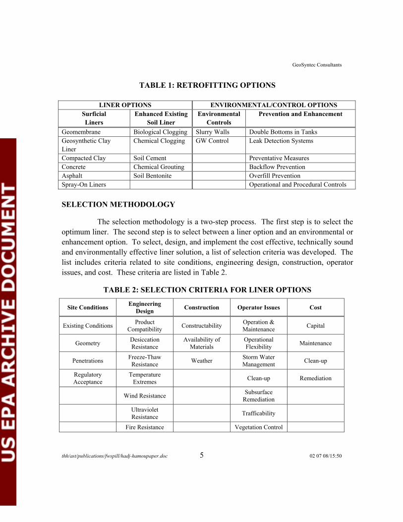
There are two major groups of options for retrofitting an AST facility to minimize the risk of contamination of the environment by releases. The first group includes the installation of liners in the secondary containment areas or enhancing the soil in place. The second group includes the installation of environmental controls or the use of preventative measures or enhancement of the tanks. Table 1 below lists different options for each of the two groups.
thh/ast/publications/fwspill/hadj-hamoupaper.doc 4 02 07 08/15:50
GeoSyntec Consultants
TABLE 1: RETROFITTING OPTIONS
LINER OPTIONS ENVIRONMENTAL/CONTROL OPTIONS Surficial Liners
Enhanced Existing Soil Liner
Environmental Controls
Prevention and Enhancement
Geomembrane Biological Clogging Slurry Walls Double Bottoms in Tanks Geosynthetic Clay Liner
Chemical Clogging GW Control Leak Detection Systems
Compacted Clay Soil Cement Preventative Measures Concrete Chemical Grouting Backflow Prevention Asphalt Soil Bentonite Overfill Prevention Spray-On Liners Operational and Procedural Controls
SELECTION METHODOLOGY
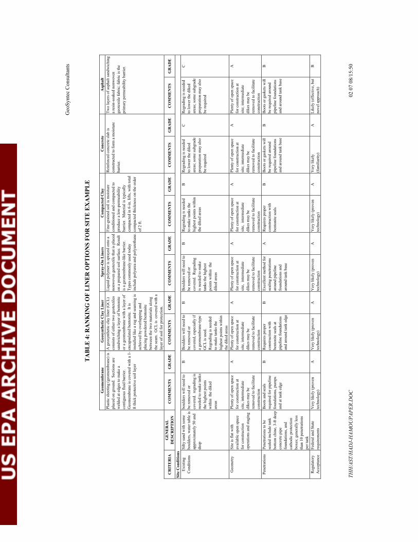
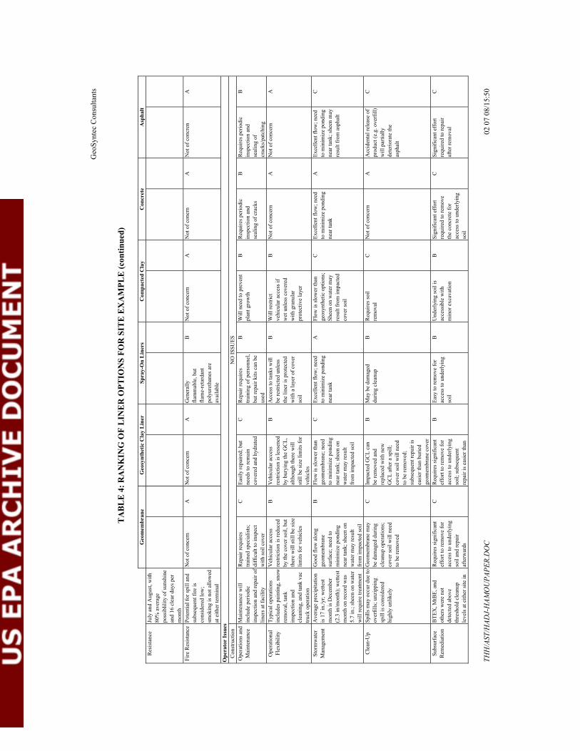
The selection methodology is a two-step process. The first step is to select the optimum liner. The second step is to select between a liner option and an environmental or enhancement option. To select, design, and implement the cost effective, technically sound and environmentally effective liner solution, a list of selection criteria was developed. The list includes criteria related to site conditions, engineering design, construction, operator issues, and cost. These criteria are listed in Table 2.
TABLE 2: SELECTION CRITERIA FOR LINER OPTIONS
Site Conditions Engineering Design Construction or Issues Cost
Existing Conditions Product Compatibility Constructability Operation &
Maintenance Capital
Geometry Desiccation Resistance
Availability of Materials
Operational Flexibility Maintenance
Penetrations Freeze-Thaw Resistance Weather Storm Water
Management Clean-up
Regulatory Acceptance
Temperature Extremes Clean-up Remediation
Wind Resistance Subsurface Remediation
Ultraviolet Resistance Trafficability
Fire Resistance Vegetation Control
Operat
thh/ast/publications/fwspill/hadj-hamoupaper.doc 5 02 07 08/15:50
GeoSyntec Consultants
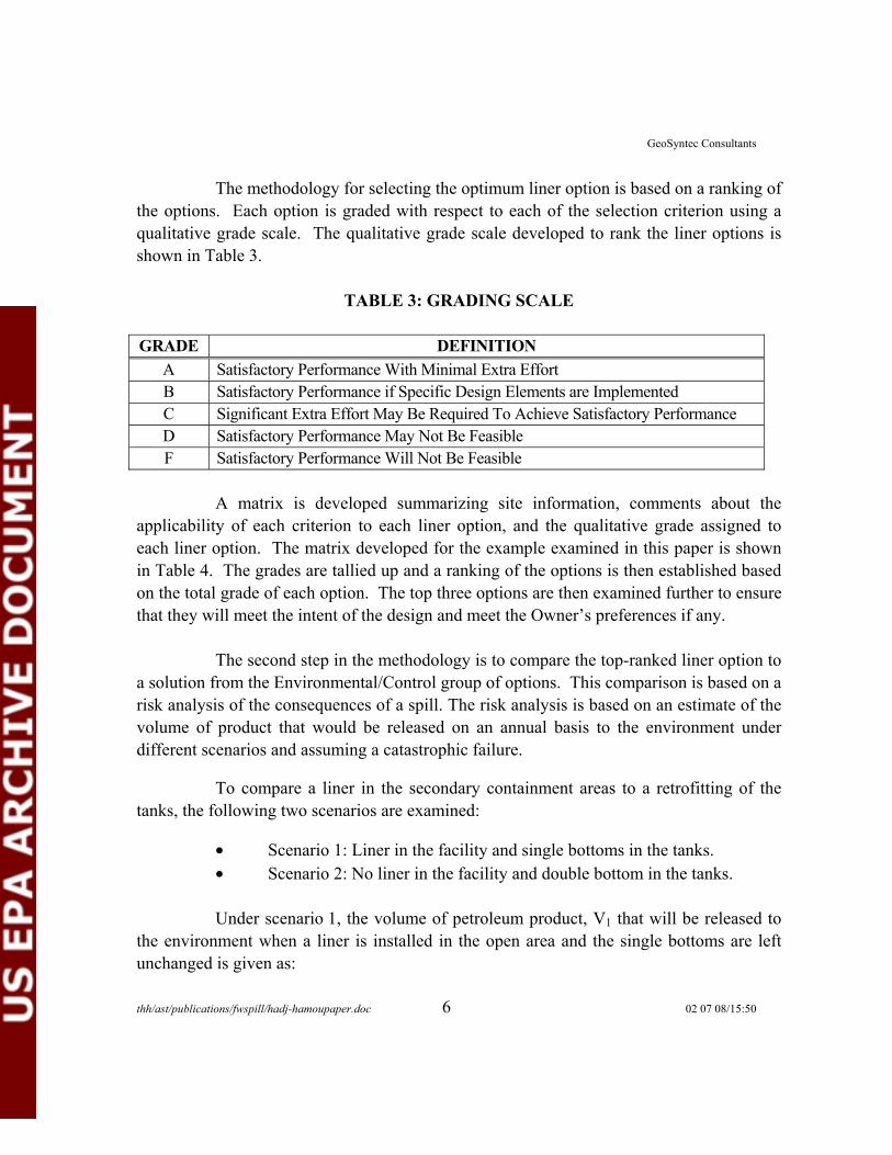
The methodology for selecting the optimum liner option is based on a ranking of the options. Each option is graded with respect to each of the selection criterion using a qualitative grade scale. The qualitative grade scale developed to rank the liner options is shown in Table 3.
TABLE 3: GRADING SCALE
GRADE A Satisfactory Performance With Minimal Extra Effort B Satisfactory Performance if Specific Design Elements are Implemented C Significant Extra Effort May Be Required To Achieve Satisfactory Performance D Satisfactory Performance May Not Be Feasible F Satisfactory Performance Will Not Be Feasible
DEFINITION
A matrix is developed summarizing site information, comments about the applicability of each criterion to each liner option, and the qualitative grade assigned to each liner option. The matrix developed for the example examined in this paper is shown in Table 4. The grades are tallied up and a ranking of the options is then established based on the total grade of each option. The top three options are then examined further to ensure that they will meet the intent of the design and meet the Owner’s preferences if any.
The second step in the methodology is to compare the top-ranked liner option to a solution from the Environmental/Control group of options. This comparison is based on a risk analysis of the consequences of a spill. The risk analysis is based on an estimate of the volume of product that would be released on an annual basis to the environment under different scenarios and assuming a catastrophic failure.
To compare a liner in the secondary containment areas to a retrofitting of the tanks, the following two scenarios are examined:
• Scenario 1: Liner in the facility and single bottoms in the tanks. • Scenario 2: No liner in the facility and double bottom in the tanks.
Under scenario 1, the volume of petroleum product, V1 that will be released to the environment when a liner is installed in the open area and the single bottoms are left unchanged is given as:
thh/ast/publications/fwspill/hadj-hamoupaper.doc 6 02 07 08/15:50

GeoSyntec Consultants
V1 = (Leakage Rate through Bottom) x (Area of Bottom) x (Time)
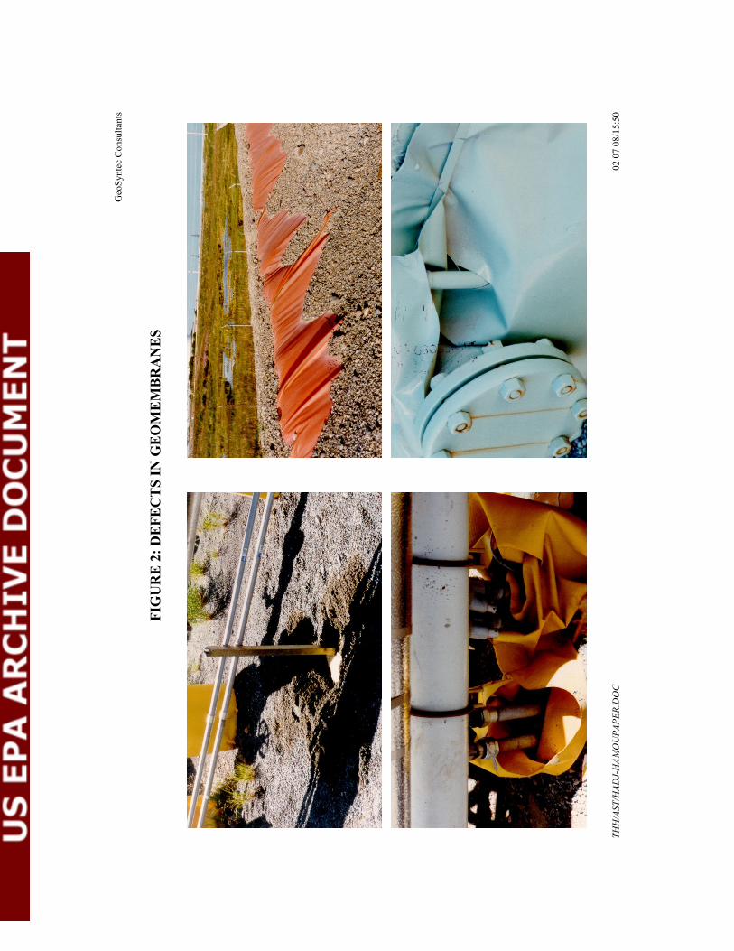
Note that it is assumed in these scenarios the bottoms have defects and/or pinholes and that the liner installed in the secondary containment does not. This latter assumption is conservative as depths in liners installed in tank farms have been observed. Defects in liners come from puncture, incomplete seams, or gaps at boots installed around pipe penetrations (Figure 2). Studies by Giroud and Bonaparte (1989) have shown that geomembrane liners installed with strict construction quality assurance could be considered to have one to two defects per acre with a diameter of 2 mm. Using electric detection surveys Laine (1991) has shown that liners installed with strict construction quality assurance could have five or more defects per acre with diameter less than 0.5 mm. In tank farms where numerous boots are installed around pipe penetrations, support, and others appurtenances it is expected that even with a very strict construction quality assurance the number of defects will exceeds the numbers listed previously. The importance of these defects is very important as they lower the effectiveness of the liner to function as an impervious barrier. The role of such defect in lowering the effectiveness of liner was further demonstrated by King et al. (1997). King et al. (1997) showed that a geomembrane with a defect rate of about 2 in2/acre provided the same level of protection in the case of a catastrophic spill as a soil with a hydraulic conductivity of 10-5 cm/s.
Under scenario 2, the volume of petroleum product, V2 that will be released to the environment when double bottoms are installed in each AST and the open area within the secondary containment area is left unchanged is given as:
V2 = (Leakage Rate through Double Bottom) x (Area of Double Bottom) x (Time) + (Volume of Product Infiltrated in Soil Following A Hypothetical Catastrophic Failure)
The better scenario is the scenario that will minimize the volume of petroleum product release to the environment over the economic life of the tank farm.
Define a performance ratio to compare the two options:
PR=V1 / V2
thh/ast/publications/fwspill/hadj-hamoupaper.doc 7 02 07 08/15:50

GeoSyntec Consultants
Because PR is a function of time and of the volume of product infiltrated in the soil, it will depend upon the site characteristics such as the hydraulic conductivity of the soil, and will range from values less than one to values greater than 1. PR equals to 1 indicates that the two options are comparable. A PR greater than 1 indicates that the release to the environment is greater under Scenario 1 and, therefore, that Scenario 2 is a better scenario and installing double bottoms at the facility is a better option for protection of the environment than installing a liner in the facility while leaving the tank bottom untouched. The use of PR allows the owner to measure the level of risk he is willing to assume when considering retrofitting options.
EXAMPLE
The methodology discussed above is applied to a tank farm located inland in the Pacific Northwest. The tank farm includes 7 tanks storing refined petroleum product. The following information is available about the terminal:
TABLE 5: INFORMATION ABOUT SITE
Secondary Containment Areas: Total Area: 140,000ft2
Open Area: 83,000ft2
Area of Tank Bottom: 57,000ft2
Height of Dikes: 5ft
Largest Tank: Diameter: 120 ft Safe Fill Height: 46ft Volume: ≅ 93,000 bbls
Soil: Homogenous Sand Deposit k = 10-5 m/sec Thickness > 100ft Groundwater Depth: 50ft
Tank Bottoms: Average pinhole diameter d = 1 mm (0.04 in.) Average number of pinholes: 1/acre of bottom
Table 4 shows the ranking of the liner options for the facility. The ranking shows that a geomembrane is the preferred liner option. The second step is to compare installation of a geomembrane at the facility versus retrofitting the tanks by installing double bottoms with leak detection systems, a system of overfill protection at the terminal, and a spill recovery system. The spill recovery system consists of a pump with a pumping capacity of 2,500 gpm that can be activated in no less than 6 hours after a catastrophic spill has occurred.
thh/ast/publications/fwspill/hadj-hamoupaper.doc 8 02 07 08/15:50

GeoSyntec Consultants
The performance ratio PR discussed above is evaluated in the following. The volume of petroleum product, V1 that will be released to the environment on an annual basis when geomembranes are installed in the open area and the single bottoms are left unchanged is given as:
V1 = (Leakage Rate through Single Bottom) x (Area of Single Bottom) x (Time)
Using the Giroud et al. method (Giroud et al., 1997), the leakage rate is evaluated as a function of product height. Figure 3 shows flow in gallon/day as function of product height ranging from 0 to 50 ft. Under the product fill height of 46 ft in the tank, the leakage rate is 167 gallons per day (gpd) per acre.
V1= (167 gpd/acre)*(57,000ft2/43.560 ft2/acre*(365 days/year)/(42 gallons/bbl) V1= 1899 bbls/year
The volume of petroleum product, V2 that will be released to the environment on an annual basis when double bottoms are installed in each AST and the open area within the secondary containment area is left unchanged is given as:
V2 = (Leakage Rate through Double Bottom) x (Area of Double Bottom) x (Time) + (Volume of Product Infiltrated in Soil) following the catastrophic spill.
For a double bottom tank, we assume that there is about 0.5 in of product that may have gone undetected by the leak detection system on top of the original old bottom. Therefore we assumed that there is 0.5 in. of head driving the flow out of the double bottom system. Under this assumption the flow is about 2.88 gpd/acre (Figure 2).
thh/ast/publications/fwspill/hadj-hamoupaper.doc 9 02 07 08/15:50

GeoSyntec Consultants
The volume of product infiltrated in the ground is estimated using the numerical model XSLIM (eXpanded Soil Liner Infiltration Model) (Myers et al, 2001) developed to assess the effectiveness of soil liners in controlling hypothetical catastrophic spills in secondary containment areas. XSLIM simulates penetration of petroleum product into the soil liner and the underlying vadose zone. In addition, XSLIM takes into account the response time from the operators, the pumping rate, and the decreasing ponding height of petroleum product as it is recovered from the secondary containment area. The calculated depth of infiltration of product in the ground is 0.54ft. Consequently the volume of product infiltrated in the ground is equal to the depth times the area times the porosity of the soil:
V2 = (2.88) * (57000/43560)*(365 days/year)/(42 gallons/bbl)+ (0.54ft)*(83,000ft2)/(5.6ft3/bbl)*(0.35) V2=2801bbls + 32.8 bbls/year
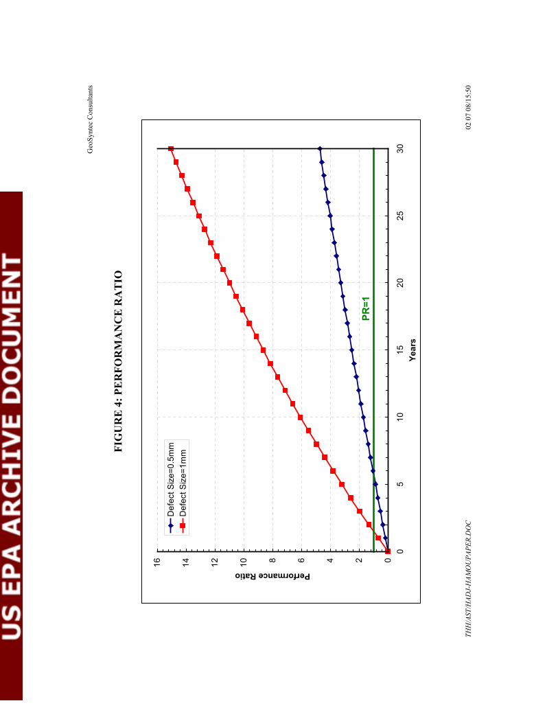
To compare the two retrofitting option the performance ratio defined as:
PR= V1 / V2
is evaluated as a function of time and plotted in Figure 4. Figure 4 shows that the performance ratio is one at 1.5 years. This indicates that unless the return period of a catastrophic failure of the largest tank containing 93,000 bbls is less than 1.5 years then installing double bottoms in the seven tanks at the tank farms provide better protection of the environment. The performance ratio was calculated assuming a defect size of 0.5mm and is reported in Figure 4. Figure 4 indicates that the PR is equals 1 after 6 years. Unless a catastrophic spill occurs every 6 years, a better protection of the environment is obtained retrofitting the tank bottoms rather than placing a liner at the facility and leaving the tank bottom untouched.
thh/ast/publications/fwspill/hadj-hamoupaper.doc 10 02 07 08/15:50

GeoSyntec Consultants
CONCLUSION
This paper presented a methodology to select the optimum engineering alternative at bulk storage facilities. The methodology provides tools to select the optimum liner option and tools to compare the liner option to alternative approach to secondary containment lining. The methodology was applied to an example and it was shown that for the site-specific conditions of the facility the optimum engineering alternative to protect the environment is to install double bottom in the tanks with an overfill protection system.
The opinions expressed in this paper are those of the authors and one should not assume endorsement by the US EPA.
REFERENCES
American Petroleum Institute (1997), “Liquid Release Prevention and Detection Measures for Aboveground Storage Tanks, Publication Number 340, October.
Cutter Information Corporation (1999), Oil Spill Response Reference Guide.
Giroud, J.P., and Bonaparte, R. (1989), “Leakage Through Liners Constructed with Geomembranes – Part II Composite Liners,” Geotextiles and Geomembranes, pages 79-111.
Giroud, J.P., King, T.D., Sanglerat, T.R., Hadj-Hamou, T. and Khire, M.V. (1997), “Evaluation of the Rate of Liquid Migration Through Defects of a Geomembrane Placed on a Semi-Permeable Soil”, Geosynthetics International, Vol. 4., Nos. 3-4, pp.349-372
King, T.D., Haffner, J., Sanglerat, T.R., Hadj-Hamou, T. and Williamson, T.A. (1997), “Aboveground Storage Tank (AST) Secondary Containment Enhancement”, American Petroleum Institute 62nd Spring Refining Meeting, Environmental Symposium, San Diego, 7-9 April.
thh/ast/publications/fwspill/hadj-hamoupaper.doc 11 02 07 08/15:50
GeoSyntec Consultants
Laine, D.L. (1991), “Analysis of Pinhole Seam Leaks Located in Geomembrane liners Using the Electrical Leak Location Method – Case Histories,” Proceedings of Geosynthetics 1991, Volume 1, pp. 239-253, Atlanta.
Myers, P., Luccioni, L., Palmer, B., Hadj-Hamou, T., and Sanglerat, T.R. (2001), “Sufficiently Impervious Secondary Containment for AST’s,” Proceedings of 21st Annual International Operating Conference and Trade Show, Independent Liquid Terminals Association, Houston, Texas, 11-14 June.
National Fire Protection Association (1993), Flammable and Combustible Liquids Code, NFPA 30.
United States Environmental Protection Agency (1996), EPA Liner Study, Report to Congress, Section 4113(a) of the Oil Pollution Act of 1990, OSWER 9380.0-24, EPA 540/R95/041, PB 95-963538, May.
thh/ast/publications/fwspill/hadj-hamoupaper.doc 12 02 07 08/15:50
Geo
Synt
ec C
onsu
ltant
s
TA
BL
E 4
: RA
NK
ING
OF
LIN
ER
OPT
ION
S FO
R S
ITE
EX
AM
PLE
Geo
mem
bran
e G
eosy
nthe
tic C
lay
Lin
er
Spra
y-O
n L
iner
s C
ompa
cted
Cla
y C
oncr
ete
Asp
halt
Plas
tic sh
eetin
g (g
eom
embr
ane)
is
plac
ed o
n gr
ound
. ec
tions
are
w
elde
d at
edg
es to
mak
e a
cont
iguo
us fl
uid
barr
ier.
Geo
mem
bran
e is
cov
ered
with
a 1
-ft
thic
k pr
otec
tive
soil
laye
r
A g
eosy
nthe
tic c
lay
liner
(GC
L)
cons
ists
of e
ither
two
geot
extil
es
sand
wic
hing
a la
yer o
f ben
toni
te
or a
geo
mem
bran
e w
ith a
laye
r of
enca
psul
ated
ben
toni
te.
t is
inst
alle
d lik
e a
rug
and
seam
ing
is
achi
eved
by
over
lapp
ing
and
plac
ing
pow
dere
d be
nton
ite
betw
een
the
two
mat
eria
ls a
long
th
e se
am.
is
laye
r of s
oil f
or p
rote
ctio
n.
Liqu
id p
olym
er is
spra
yed
onto
a
nonw
oven
geo
text
ile th
at is
pla
ced
on a
pre
pare
d so
il su
rfac
e.
esul
t is
a g
eom
embr
ane-
like
barr
ier.
Type
s com
mon
ly u
sed
toda
y in
clud
e po
lyur
ea a
nd p
olyu
reth
ane.
Fine
-gra
ined
soil
is m
oist
ure
cond
ition
ed a
nd c
ompa
cted
to
prod
uce
a lo
w-p
erm
eabi
lity
barr
ier.
pica
lly
com
pact
ed in
6-in
. lift
s, w
ith to
tal
com
pact
ed th
ickn
ess o
n th
e or
der
of 2
ft.
Rei
nfor
ced
conc
rete
slab
is
cons
truct
ed to
form
a m
oist
ure
barr
ier.
Two
laye
rs o
f asp
halt
sand
wic
hing
a
resi
n-so
aked
non
wov
en
geot
extil
e fa
bric
; fab
ric is
the
prim
ary
perm
eabi
lity
barr
ier.
CR
ITE
RIA
G
EN
ER
AL
D
ESC
RIP
TIO
NC
OM
ME
NT
S G
RA
DE
C
OM
ME
NT
S G
RA
DE
C
OM
ME
NT
S G
RA
DE
C
OM
ME
NT
S G
RA
DE
C
OM
ME
NT
S G
RA
DE
C
OM
ME
NT
S G
RA
DE
Site
Con
ditio
ns
Exis
ting
Con
ditio
ns
Silty
sand
with
som
e bo
ulde
rs, w
ater
tabl
e is
ap
prox
imat
ely
50 a
nd
deep
boul
ders
will
nee
d to
be
rem
oved
or
cove
red.
ra
ding
is
need
ed to
mak
e ta
nks
the
high
est p
oint
s w
ithin
ar
eas
B
Bou
lder
s will
nee
d to
be
rem
oved
or
cove
red,
esp
ecia
lly if
a
geom
embr
ane-
type
G
CL
is u
sed.
R
egra
ding
is n
eede
d to
mak
e ta
nks t
he
high
est p
oint
s with
in
the
dike
d ar
eas
B
Bou
lder
s will
nee
d to
be
rem
oved
or
cove
red.
ra
ding
is
nee
ded
to m
ake
tank
s the
hig
hest
po
ints
with
in
dike
d ar
eas
B
Reg
radi
ng is
nee
ded
to m
ake
tank
s the
hi
ghes
t poi
nts w
ithin
th
e di
ked
area
s
B
Reg
radi
ng is
nee
ded
to lo
wer
the
dike
d ar
eas;
som
e su
bgra
de
prep
arat
ion
may
als
o be
requ
ired
C
Reg
radi
ng is
nee
ded
to lo
wer
the
dike
d ar
eas;
som
e su
bgra
de
prep
arat
ion
may
als
o be
requ
ired
Geo
met
ry
Site
is fl
at w
ith
avai
labl
e op
en sp
ace
for c
onst
ruct
ion
oper
atio
ns a
nd st
agin
g
Plen
ty o
f ope
n sp
ace
for c
onst
ruct
ion
at
site
, int
erm
edia
te
dike
s may
be
rem
oved
to fa
cilit
ate
cons
truct
ion
A
Plen
ty o
f ope
n sp
ace
for c
onst
ruct
ion
at
site
, int
erm
edia
te
dike
s may
be
rem
oved
to fa
cilit
ate
cons
truct
ion
A
Plen
ty o
f ope
n sp
ace
for c
onst
ruct
ion
at
site
, rm
edia
te
dike
s may
be
rem
oved
to fa
cilit
ate
cons
truct
ion
A
Plen
ty o
f ope
n sp
ace
for c
onst
ruct
ion
at
site
, rm
edia
te
dike
s may
be
rem
oved
to fa
cilit
ate
cons
truct
ion
A
Plen
ty o
f ope
n sp
ace
for c
onst
ruct
ion
at
site
; int
erm
edia
te
dike
s may
be
rem
oved
to fa
cilit
ate
cons
truct
ion
A
Plen
ty o
f ope
n sp
ace
for c
onst
ruct
ion
at
site
; int
erm
edia
te
dike
s may
be
rem
oved
to fa
cilit
ate
cons
truct
ion
A
Pene
tratio
ns
tratio
ns to
be
seal
ed in
clud
e ta
nk
botto
m c
hine
, 3-f
t dee
p co
ncre
te p
ipe
foun
datio
ns, a
nd
cath
odic
pro
tect
ion
boxe
s; g
ener
ally
less
th
an 1
0 pe
netra
tions
pe
r tan
k
Boo
ts a
nd se
als
requ
ired
for p
ipel
ine
foun
datio
ns, p
umps
an
d at
tank
edg
e
B
Req
uire
s pro
per
cons
truct
ion
with
be
nton
ite se
als a
t pi
pelin
e fo
unda
tions
an
d ar
ound
tank
edg
e
B
Exce
llent
met
hod
for
seal
ing
pene
tratio
ns
arou
nd p
ipel
ine
foun
datio
ns a
nd
arou
nd ta
nk b
ase
A
prop
er
cons
truct
ion
with
be
nton
ite se
als
B
Boo
ts o
r gas
kets
will
be
requ
ired
arou
nd
pipe
line
foun
datio
ns
and
arou
nd ta
nk b
ase
B
Boo
ts o
r gas
kets
will
be
requ
ired
arou
nd
pipe
line
foun
datio
ns
and
arou
nd ta
nk b
ase
B
Reg
ulat
ory
Acc
epta
nce
Fede
ral a
nd S
tate
re
quire
men
ts
Ver
y lik
ely
(pro
ven
tech
nolo
gy)
A
Ver
y lik
ely
(pro
ven
tech
nolo
gy)
A
Ver
y lik
ely
(pro
ven
tech
nolo
gy)
A
Ver
y lik
ely
(pro
ven
tech
nolo
gy)
A
likel
y (f
amili
arity
) A
Li
kely
(eff
ectiv
e, b
ut
nove
l app
roac
h)
B
S
I
GC
Lco
vere
d w
ith a
RM
ater
ial i
s ty
reg
the
dike
d
Reg
the
inte
inte
Pene
Req
uire
s
Ver
y
THH
/AST
/HAD
J-H
AMO
UPA
PER.
DO
C
02 0
7 08
/15:
50
C

Geo
Synt
ec C
onsu
ltant
s
TA
BL
E 4
: RA
NK
ING
OF
LIN
ER
OPT
ION
S FO
R S
ITE
EX
AM
PLE
(con
tinue
d)
Geo
mem
bran
e G
eosy
nthe
tic C
lay
Lin
er
Spra
y-O
n L
iner
s C
ompa
cted
Cla
y C
oncr
ete
Asp
halt
Eng
inee
ring
Des
ign
Prod
uct
Com
patib
ility
Ta
nks c
onta
in c
omm
on
petro
leum
hyd
roca
rbon
pr
oduc
ts
Lim
ited
redu
ctio
n in
st
reng
th p
rope
rties
af
ter e
xpos
ure
to
hydr
ocar
bons
for
mos
t geo
mem
bran
e ty
pes.
stre
ngth
est
imat
es
can
be u
sed
for
desi
gn (I
.e. p
unct
ure
resi
stan
ce, w
eld
stre
ngth
, etc
.).
B
Not
sign
ifica
ntly
im
pact
ed b
y ex
posu
re to
hy
droc
arbo
ns if
hy
drat
ed
B
Not
of c
once
rn w
ith
poly
urea
; of m
inor
co
ncer
n w
ith
poly
uret
hane
B
If so
il is
dry
whe
n ex
pose
d to
hy
droc
arbo
ns,
perm
eabi
lity
will
be
high
; soi
l sho
uld
rem
ain
hydr
ated
C
Not
of c
once
rn
A
prod
uct
will
par
tially
de
terio
rate
the
asph
alt
D
Des
sica
tion
Res
ista
nce
Ave
rage
ann
ual
prec
ipita
tion
is 1
7 in
.; dr
iest
mon
ths a
re Ju
ly,
Aug
ust a
nd S
epte
mbe
r (a
vera
ge m
onth
ly
prec
ipita
tion
is le
ss
than
1 in
ch)
Not
of c
once
rn
A
Des
sica
tion
will
in
crea
se p
erm
eabi
lity
to a
n un
acce
ptab
le
leve
l; G
CL
mus
t re
mai
n hy
drat
ed;
irrig
atio
n m
ay b
e re
quire
d in
sum
mer
m
onth
s
C
Not
of c
once
rn
A
dess
icat
ion
will
in
crea
se p
erm
eabi
lty
in h
ighe
r-pl
astic
ity
mat
eria
ls; i
rrig
atio
n m
ay b
e re
quire
d in
su
mm
er m
onth
s
C
Not
of c
once
rn
A
Vol
atile
frac
tion
in
asph
alt w
ill
evap
orat
e w
ith ti
me;
m
ay in
duce
som
e cr
acki
ng
C
Free
ze T
haw
R
esis
tanc
e Fi
ve m
onth
s out
of t
he
year
(Nov
embe
r-M
arch
) hav
e av
erag
e hi
gh a
nd lo
w
tem
pera
ture
s tha
t are
ab
ove
and
belo
w
free
zing
Not
of c
once
rn
A
GC
L re
cove
rs fr
om
free
ze-th
aw c
ycle
s B
N
ot o
f con
cern
A
M
ay in
duce
m
icro
crac
king
and
re
duce
surf
icia
l pe
rmea
bilit
y
C
reez
e-th
aw m
ay
wor
sen
exis
ting
crac
king
C
Free
ze-th
aw m
ay
wor
sen
exis
ting
crac
king
C
Tem
pera
ture
Ex
trem
es
Diff
eren
ce b
etw
een
aver
age
annu
al h
igh
and
low
tem
pera
ture
is
61 d
egre
es; d
iffer
ence
be
twee
n al
l-tim
e hi
gh
and
all-t
ime
low
is 1
33
degr
ees
Tem
pura
ture
va
riatio
ns m
ay
indu
ce st
ress
co
ncen
tratio
ns a
nd
geom
embr
ane
rupt
ure
at w
elds
and
th
e ge
omem
bran
e m
ay b
ecom
e br
ittle
at
low
tem
pera
ture
s, bu
t the
cov
er so
il w
ill re
duce
the
effe
ct
B
Not
of c
once
rn
A
Som
e po
lyur
etha
nes
may
bec
ome
britt
le a
t lo
w te
mpe
ratu
res
B
Not
of c
once
rn
A
Tem
pera
ture
ex
trem
es m
ay in
duce
cr
acki
ng
C
Tem
pera
ture
ex
trem
es m
ay in
duce
cr
acki
ng
C
Win
d R
esis
tanc
e W
indi
est m
onth
s are
M
arch
and
Apr
il (a
vera
ge w
ind
spee
d =
13 m
ph)
Not
of c
once
rn
A
Not
of c
once
rn
Req
uire
s anc
horin
g at
dik
es; b
alla
st in
op
en a
reas
may
als
o be
requ
ired
B
Not
of c
once
rn
A
Not
of c
once
rn
A
Not
of c
oncr
en
A
Ultr
avio
let
Sunn
iest
mon
ths a
re
Not
of c
once
rn
A
Not
of c
once
rn
A
Lim
ited
Con
cern
B
N
ot o
f con
cern
A
N
ot o
f con
ern
A
Not
of c
oncr
en
Red
uced
Rel
ease
d
F
A
A
THH
/AST
/HAD
J-H
AMO
UPA
PER.
DO
C
02 0
7 08
/15:
50
Geo
Synt
ec C
onsu
ltant
s
TA
BL
E 4
: RA
NK
ING
OF
LIN
ER
OPT
ION
S FO
R S
ITE
EX
AM
PLE
(con
tinue
d)
Geo
mem
bran
e G
eosy
nthe
tic C
lay
Lin
er
Spra
y-O
n L
iner
s C
ompa
cted
Cla
y C
oncr
ete
Asp
halt
Res
ista
nce
July
and
Aug
ust,
with
80
% a
vera
ge
poss
iblil
ity o
f sun
shin
e an
d 16
cle
ar d
ays p
er
mon
th
Fire
Res
ista
nce
Pote
ntia
l for
spill
and
su
bseq
uent
fire
is
cons
ider
ed lo
w;
smok
ing
is n
ot a
llow
ed
at e
ither
term
inal
Not
of c
once
rn
A
Not
of c
once
rn
A
Gen
eral
ly
flam
mab
le, b
ut
flam
e-re
tard
ant
poly
uret
hane
s are
av
aila
ble
B
Not
of c
once
rn
A
Not
of c
oner
n A
N
ot o
f con
cren
A
Ope
rato
r Is
sues
C
onst
ruct
ion
NO
ISSU
ES
Ope
ratio
ns a
nd
Mai
nten
ance
M
aint
enan
ce w
ill
incl
ude
perio
dic
insp
ectio
n an
d re
pair
of
liner
s at f
acili
ty
Rep
air r
equi
res
train
ed sp
ecia
lists
; di
ffic
ult t
o in
spec
t w
ith so
il co
ver
C
Easi
ly re
paire
d; b
ut
need
s to
rem
ain
cove
red
and
hydr
ated
C
requ
ires
train
ing
of p
erso
nnel
, bu
t rep
air k
its c
an b
e us
ed
B
Will
nee
d to
pre
vent
pl
ant g
row
th
B
Req
uire
s per
iodi
c in
spec
tion
and
seal
ing
of c
rack
s
B
Req
uire
s per
iodi
c in
spec
tion
and
seal
ing
of
crac
ks/p
atch
ing
B
Ope
ratio
nal
Flex
ibili
ty
Typi
cal o
pera
tions
in
clud
es p
aint
ing,
snow
re
mov
al, t
ank
insp
ectio
n an
d cl
eani
ng, a
nd ta
nk v
ac
truck
ope
ratio
n
Veh
icul
ar a
cces
s re
stric
tion
is re
duce
d by
the
cove
r soi
l, bu
t th
ere
will
still
be
size
lim
its fo
r veh
icle
s
B
cula
r acc
ess
rest
rictio
n is
less
ened
by
bur
ying
the
GC
L,
alth
ough
ther
e w
ill
still
be
size
lim
its fo
r ve
hicl
es
B
Acc
ess t
o ta
nks w
ill
be re
stric
ted
unle
ss
the
liner
is p
rote
cted
w
ith a
laye
r of c
over
so
il
B
Will
rest
rict
vehi
cula
r acc
ess i
f w
et u
nles
s cov
ered
w
ith g
ranu
lar
prot
ectiv
e la
yer
B
Not
of c
once
rn
A
Not
of c
once
rn
A
Stor
mw
ater
M
anag
emen
t A
vera
ge p
reci
pita
tion
is 1
7 in
./yr;
wet
test
m
onth
is D
ecem
ber
(2.3
in/m
onth
); w
ette
st
mon
th o
n re
cord
was
5.
7 in
.; sh
een
on w
ater
w
ill re
quire
trea
tmen
t
Goo
d flo
w a
long
ge
omem
bran
e su
rfac
e; n
eed
to
min
imiz
e po
ndin
g ne
ar ta
nk; s
heen
on
wat
er m
ay re
sult
from
impa
cted
soil
B
Flow
is sl
ower
than
ge
omem
bran
e; n
eed
to m
inim
ize
pond
ing
near
tank
; she
en o
n w
ater
may
resu
lt fr
om im
pact
ed so
il
C
Exce
llent
flow
; nee
d to
min
imiz
e po
ndin
g ne
ar ta
nk
A
Flow
is sl
ower
than
ge
osyn
thet
ic o
ptio
ns;
Shee
n on
wat
er m
ay
resu
lt fr
om im
pact
ed
cove
r soi
l
C
Exce
llent
flow
; nee
d to
min
imiz
e po
ndin
g ne
ar ta
nk
A
Exce
llent
flow
; nee
d to
min
imiz
e po
ndin
g ne
ar ta
nk; s
heen
may
re
sult
from
asp
halt
C
Cle
an-U
p Sp
ills m
ay o
ccur
due
to
over
fills
; unz
ippi
ng
spill
is c
onsi
dere
d hi
ghly
unl
ikel
y
Geo
mem
bran
e m
ay
be d
amag
ed d
urin
g cl
eanu
p op
erat
ions
; co
ver s
oil w
ill n
eed
to b
e re
mov
ed
C
Impa
cted
GC
L ca
n be
rem
oved
and
re
plac
ed w
ith n
ew
GC
L af
ter a
spill
; co
ver s
oil w
ill n
eed
to b
e re
mov
ed;
subs
eque
nt re
pair
is
easi
er th
an b
urie
d ge
omem
bran
e co
ver
B
May
be
dam
aged
du
ring
clea
nup
B
Req
uire
s soi
l re
mov
al
C
Not
of c
once
rn
A
Acc
iden
tal r
elea
se o
f pr
oduc
t (e.
g. o
verf
ill)
will
par
tially
de
terio
rate
the
asph
alt
C
Subs
urfa
ce
Rem
edia
tion
BTE
X, M
tBE,
and
ot
hers
wer
e no
t de
tect
ed a
bove
th
resh
old
clea
nup
leve
ls a
t eith
er si
te in
Req
uire
s sig
nific
ant
effo
rt to
rem
ove
for
acce
ss to
und
erly
ing
soil
and
repa
ir af
terw
ards
C
quire
s sig
nific
ant
effo
rt to
rem
ove
for
acce
ss to
und
erly
ing
soil;
subs
eque
nt
repa
ir is
eas
ier t
han
B
Easy
to re
mov
e fo
r ac
cess
to u
nder
lyin
g so
il
B
Und
erly
ing
soil
is
acce
ssib
le w
ith
min
or e
xcav
atio
n
B
Sign
ifica
nt e
ffor
t re
quire
d to
rem
ove
the
conc
rete
for
acce
ss to
und
erly
ing
soil
C
nific
ant e
ffor
t re
quire
d to
repa
ir af
ter r
emov
al
C
Rep
air
Veh
i
Re
Sig
THH
/AST
/HAD
J-H
AMO
UPA
PER.
DO
C
02 0
7 08
/15:
50

Geo
Synt
ec C
onsu
ltant
s
TA
BL
E 4
: RA
NK
ING
OF
LIN
ER
OPT
ION
S FO
R S
ITE
EX
AM
PLE
(con
tinue
d)
Geo
mem
bran
e G
eosy
nthe
tic C
lay
Lin
er
Spra
y-O
n L
iner
s C
ompa
cted
Cla
y C
oncr
ete
Asp
halt
rece
nt m
onito
ring
repo
rts; r
emed
iatio
n is
no
t con
side
red
nece
ssar
y at
this
tim
e
burie
d ge
omem
bran
e co
ver
Traf
ficab
ility
V
ehic
les r
equi
re a
cces
s to
and
aro
und
the
perim
eter
of t
he ta
nks
Traf
ficab
le if
cu
shio
ned
and
cove
red
B
cabl
e if
cush
ione
d an
d co
vere
d
B
Will
rest
rict
vehi
cula
r acc
ess t
o ta
nks;
traf
ficab
le if
cu
shio
ned
and
cove
red
C
Traf
ficab
le u
nder
dry
co
nditi
ons
B
Not
of c
once
rn
A
Not
of c
once
rn
A
Veg
etat
ion
Con
trol
Con
tain
men
t are
as a
re
perio
dica
lly sp
raye
d fo
r w
eeds
, alth
ough
som
e w
eeds
wer
e fo
und
durin
g th
e si
te
insp
ectio
n
Veg
etat
ion
cont
rol
will
redu
ce th
e po
tent
ial f
or ro
ot
pene
tratio
n
B
Esse
ntia
l C
N
ot o
f con
cern
A
Es
sent
ial f
or p
rope
r pe
rfor
man
ce
C
Not
of c
once
rn if
cr
acks
are
seal
ed
B
Not
of c
once
rn if
cr
acks
are
seal
ed
B
Cos
ts
Eco
nom
ic a
nd P
oliti
cal C
rite
ria
Cap
ital c
ost p
er
squa
re fo
ot (n
ot
incl
udin
g en
gine
erin
g an
d C
QA
)
Prel
imin
ary
cost
s to
be
used
for c
ompa
rison
pu
rpos
es o
nly
and
not
for b
id p
repa
ratio
n;
thes
e co
sts w
ill n
eed
to
be re
fined
prio
r to
bid
prep
arat
ion
Mod
erat
e to
hig
h --
$2.8
0 - 4
.30
(incl
udes
geo
text
ile
cush
ion,
boo
ts,
seal
ing
arou
nd ta
nk,
and
1 ft
prot
ectiv
e co
ver s
oil)
C
Mod
erat
e --
$2.
60 -
3.40
(inc
lude
s ge
otex
tile
cush
ion
and
1-ft
prot
ectiv
e co
ver s
oil)
C
Hig
h --
$4.
00 -
7.00
(r
ange
for f
lexi
ble
and
rigid
type
po
lyur
etha
nes)
D
Low
to m
oder
ate
--$1
.70
- 4.0
0 (f
or 2
-ft
thic
k la
yer;
incr
ease
co
st fo
r hau
ling
dist
ance
s gre
ater
than
20
mile
s; to
tal c
ost
incl
udes
gra
ding
of
exis
ting
surf
ace,
ha
ulin
g, sp
read
ing
and
com
pact
ion)
C
Hig
h --
$5.
00 -
6.60
(f
or 6
to 8
-in.
rein
forc
ed sl
ab)
D
Hig
h --
$4.
50 -
5.40
(in
clud
es
base
, and
4 in
. tot
al
asph
alt t
hick
ness
)
Mai
nten
ance
M
aint
enan
ce m
ay
incl
ude
deve
geta
tion,
pe
riod
insp
ectio
ns a
nd
repa
irs a
t eac
h te
rmin
al Lo
w (s
houl
d pr
even
t pl
ant g
row
th)
B
Mod
erat
e (G
CL
mus
t re
mai
n hy
drat
ed)
C
Low
(rep
air k
its a
re
avai
labl
e)
B
Low
(mus
t pre
vent
pl
ant g
row
th)
B
ow (p
erio
dic
insp
ectio
n an
d cr
ack
seal
ing)
B
Low
(per
iodi
c in
spec
tion
and
crac
k se
alin
g)
B
Cle
an-U
p Sp
ills m
ay o
ccur
due
to
over
fills
; unz
ippi
ng
spill
is c
onsi
dere
d hi
ghly
unl
ikel
y
Hig
h (r
emov
al o
f co
ver s
oil a
nd
poss
ible
repa
ir of
ge
omem
bran
e)
D
Hig
h (r
emov
al o
f co
ver s
oil a
nd
repl
acem
ent o
f GC
L)
D
Low
(som
e re
pair
may
be
requ
ired)
B
H
igh
(due
to so
il re
mov
al)
D
Low
B
H
igh
(rep
air o
f pa
ving
fabr
ic sy
stem
) D
Rem
edia
tion
BTE
X, M
tBE,
and
ot
hers
wer
e no
t de
tect
ed a
bove
th
resh
old
clea
nup
leve
ls a
t eith
er si
te in
re
cent
mon
itorin
g re
ports
Hig
h (d
ue to
rem
oval
of
soil
and
geom
embr
ane
and
repa
ir of
ge
omem
bran
e)
D
Mod
erat
e (d
ue to
re
mov
al o
f cov
er so
il an
d re
pair
of G
CL)
C
(rem
oval
an
d re
pair
of c
over
re
quire
d
C
Low
B
H
igh
(rem
oval
of
conc
rete
requ
ired)
D
H
igh
(rep
lace
men
t of
pavi
ng fa
bric
syst
em)
D
Ove
rall
Perf
orm
ance
Ex
celle
nt
A
Exce
llent
A
Ex
celle
nt
A
Exce
llent
A
Ex
celle
nt
A
Exce
llent
A
Traf
fi
6 in
. to
1 ft
L
Mod
erat
e
THH
/AST
/HAD
J-H
AMO
UPA
PER.
DO
C
02 0
7 08
/15:
50
C

Geo
Synt
ec C
onsu
ltant
s
TA
BL
E 4
: RA
NK
ING
OF
LIN
ER
OPT
ION
S FO
R S
ITE
EX
AM
PLE
(con
tinue
d)
Geo
mem
bran
e G
eosy
nthe
tic C
lay
Lin
er
Spra
y-O
n L
iner
s C
ompa
cted
Cla
y C
oncr
ete
Asp
halt
Ove
rall
Rel
iabi
lity
Goo
d B
A
vera
ge
C
Goo
d B
A
vera
ge
C
Ave
rage
C
A
vera
ge
Cri
tical
Pe
rfor
man
ce
and
Rel
iabi
lity
Issu
es
Prop
er c
onst
ruct
ion
and
CQ
A a
re
impo
rtant
to a
chie
ve
acce
ptab
le
perf
orm
ance
; po
tent
ially
hig
h cl
eanu
p co
sts
GC
L m
ust b
e in
itial
ly c
onfin
ed a
nd
hydr
ated
rem
ain
conf
ined
and
hy
drat
ed to
per
form
pr
oper
ly; p
oten
tially
hi
gh c
lean
up c
osts
Susc
eptib
ility
to
dam
age
(alth
ough
no
t as s
usce
ptib
le a
s a
geom
embr
ane)
and
co
st
Susc
eptib
le to
de
ssic
atio
n cr
acki
ng;
pote
ntia
lly h
igh
clea
nup
cost
s; h
igh
soil
proc
urem
ent
cost
s may
pro
hibi
t th
is o
ptio
n
Hig
h co
nstru
ctio
n co
sts,
pote
ntia
l for
cr
acki
ng, a
nd
pote
ntia
lly h
igh
clea
nup
effo
rt
Spill
will
che
mic
ally
at
tack
the
asph
alt;
ther
e is
a si
gnifi
cant
po
tent
ial f
or c
rack
ing
and
a po
tent
ially
hig
h cl
eanu
p ef
fort
asso
ciat
ed w
ith th
is
optio
n C
OM
ME
NT
S Th
is is
an
effe
ctiv
e,
relia
ble
liner
that
can
be
con
stru
cted
at a
m
oder
ate
cost
and
im
pose
less
hi
ndra
nce
to
oper
atio
ns th
an th
e ex
pose
d ge
omem
bran
e
This
is a
n ef
fect
ive
liner
, but
it m
ust
rem
ain
conf
ined
and
hy
drat
ed to
per
form
pr
oper
ly
This
line
r is
able
, re
liabl
e, a
nd
exce
llent
for o
dd
geom
etrie
s, bu
t so
mew
hat e
xpen
sive
This
is a
n ef
fect
ive
liner
, but
may
de
ssic
ate
if no
t hy
drat
ed;
proc
urem
ent c
osts
co
uld
be h
igh
This
line
r is
expe
nsiv
e an
d su
scep
tible
to
crac
king
, but
ef
fect
ive
and
dura
ble
This
line
r is
effe
ctiv
e, b
ut
susc
eptib
le to
ch
emic
al a
ttack
du
ring
a sp
ill
RA
NK
1
2 3
5 6
7
dur
THH
/AST
/HAD
J-H
AMO
UPA
PER.
DO
C
02 0
7 08
/15:
50
C

Geo
Synt
ec C
onsu
ltant
s
FIG
UR
E 1
: TY
PIC
AL
SE
CO
ND
AR
Y C
ON
TA
INM
EN
TS
02 0
7 08
/15:
50TH
H/A
ST/H
ADJ-
HAM
OU
PAPE
R.D
OC
Geo
Synt
ec C
onsu
ltant
s
FIG
UR
E 2
: DE
FEC
TS
IN G
EO
ME
MB
RA
NE
S
02 0
7 08
/15:
50TH
H/A
ST/H
ADJ-
HAM
OU
PAPE
R.D
OC

Geo
Synt
ec C
onsu
ltant
s
FIG
UR
E 3
: LE
AK
AG
E R
AT
E T
HR
OU
GH
DE
FEC
T IN
TA
NK
BO
TT
OM
0 25
50
75
100
125
150
175
200
225
250
0 10
0
30
0 0
Liqu
id H
eigh
t in
Feet
Flow in gpd/acre
24
5
THH
/AST
/HAD
J-H
AMO
UPA
PER.
DO
C
02 0
7 08
/15:
50
Geo
Synt
ec C
onsu
ltant
s
FIG
UR
E 4
: PE
RFO
RM
AN
CE
RA
TIO
0 2 4 6 8 10
12
14
16 0
5 10
15
20
25
30
Ye
ars
Performance Ratio
Def
ect S
ize=
0.5m
m
Def
ect S
ize=
1mm
PR=1
THH
/AST
/HAD
J-H
AMO
UPA
PER.
DO
C
02 0
7 08
/15:
50