allegany college of maryland bid set section 220100 ... · building, plumbing, mechanical, fire and...
TRANSCRIPT
Allegany College of Maryland Bid Set ACM Welcome Center M&D Project No. 17131
PLUMBING SYSTEMS GENERAL PROVISIONS 220100-1
SECTION 220100 - PLUMBING SYSTEMS GENERAL PROVISIONS
PART 1 – GENERAL
1.1 NOTE
A. All work under this section shall be subject to the General Conditions hereinbefore written for the
entire work, noting especially the reference to interlocking divisions for the Contractors responsibility under each division. All requirements under this section shall apply to work under this Division.
1.2 SCOPE
A. The Contractor shall provide and install all labor, equipment and materials shown on the Plumbing
Drawings and specified under this Division, or as required for complete and successfully operating plumbing systems.
B. It shall be the responsibility of the Contractor under this Division to ensure that work required by
other divisions for proper operation of systems or equipment furnished under this Division is performed as part of the general contract.
1.3 EXAMINATION OF PREMISES
A. The Contractor shall examine the premises and fully acquaint himself with all existing conditions
so that all problems pertaining to work under this division are fully understood. No subsequent allowance will be made in this connection for any error of judgment or negligence on the Contractor's part.
1.4 CODES
A. All plumbing work shall be done in strict accordance with all requirements of the National Standard
Plumbing Code, State Department of Health and Mental Hygiene and the NFPA including specifically NFPA 54. Connections to public utilities shall be in accordance with applicable plumbing and building codes.
B. In addition, all work shall be installed in accordance with requirements of any other applicable
building, plumbing, mechanical, fire and safety codes. Requirements set forth in the Occupational Safety and Health Act will be strictly adhered to.
C. Work shall conform to the requirements of the latest editions of the following codes, regulations,
specifications and standards:
American Society for Testing and Materials (ASTM) Sheet Metal and Air Conditioning Contractors National Association (SMACNA) Air Conditioning and Refrigeration Institute (ARI) American Society of Mechanical Engineers (ASME) Council of American Building Officials (CABO) National Electrical Code (NEC) National Electrical Manufacturers Association (NEMA) Underwriters Laboratories, Inc. (UL) United States of America Standard Institute

Allegany College of Maryland Bid Set ACM Welcome Center M&D Project No. 17131
PLUMBING SYSTEMS GENERAL PROVISIONS 220100-2
National Institute of Standards & Technology (NIST) Occupational Safety and Health Act (OSHA) American National Standards Institute (ANSI) National Fire Protection Association (NFPA) American with Disabilities Act (ADA)
1.5 LAWS, ORDINANCES, PERMITS AND FEES
A. The Contractor shall give necessary notices, obtain and pay for permits, prepare all documents
and obtain all necessary approvals of all Regulating Authorities having jurisdiction; obtain all required Certificates of Inspection for his work and deliver same to the Architect before request for acceptance and final payment for the work.
B. The Contractor shall include in the work, without extra cost to the Owner, all labor, materials,
services, apparatus, drawings (in addition to Contract Drawings and Documents) required to comply with all applicable laws, ordinances, rules and regulations.
1.6 GENERAL REQUIREMENTS
A. Everything necessary for the completion of the work and successful operation thereof, whether
they may be definitely specified or indicated or not, shall be furnished and completed in a manner corresponding with the rest of the work as though they were herein distinctly described and specifically provided for.
B. The Contractor shall have competent foremen on the premises at all times to check layout and
superintend the installation of all work included in this division of the specifications and to provide information regarding locations and sizes of chases, openings, etc., and be responsible for the accuracy of such information. The foremen shall layout and superintend the installation of all hangers, inserts, sleeves and other work in masonry and concrete in advance of the work during construction of building, giving consideration to the work of other trades to prevent interference in the location of pipes, conduits, ducts and other equipment.
C. The Contractor shall provide complete connections for equipment furnished under sections of this
division, or under other divisions, or by the Owner, which requires connections under this Division.
D. All individual pieces of equipment shall be separately valved and fitted with unions so that the individual piece of equipment may be removed for servicing without disturbing other portions of the system.
E. No beams, columns, structural members, etc., shall be sleeved for the passage of piping or ducts,
except where noted on the drawings and approved by the Architect.
F. The general arrangements and details of the equipment, piping ducts, etc., are shown on the drawings. Dimension or scales shown are approximate and must be checked at the building by the Contractor prior to the installation of any equipment or the fabrication of any equipment. Dimensions for the fabrication of piping, equipment, etc., shall not be scaled from the drawings, but shall be acquired by accurate measurements at the building. Any equipment or materials fabricated off the site, or any work which is installed on the job, which blocks the work of other trades, and is caused by the Contractor's neglect to coordinate his work with the work of other trades, shall be modified or reinstalled without change in the contract price.
G. All systems and equipment shall be arranged to operate without objectionable noise or vibration. Where objectionable noise or vibration occurs, modifications or changes shall be made until satisfactory results are obtained, at no additional cost to the Owner.

Allegany College of Maryland Bid Set ACM Welcome Center M&D Project No. 17131
PLUMBING SYSTEMS GENERAL PROVISIONS 220100-3
H. Unless otherwise indicated or required all piping shall be installed parallel to the lines of the building. Piping shall be installed straight and free of traps, sags and bends. Pipe shall be free of kinks, wrinkles and flattened sections. Piping shall properly fit into place and not be forced or stretched.
1.7 SCHEDULE
A. Within 30 days of contract date, the Contractor shall submit to the Architect for approval, a schedule
showing make, type, manufacturer's specifications for each article of equipment or specialty and shall give dimensions, rated capacity, kind of material, finish, guarantee, etc., and such other detailed information as may be required. When approved, such schedule shall be an addition to the specifications here in with, and shall be of equal force, in that no variation will be permitted except with the approval of the Architect.
1.8 QUALITY STANDARDS
A. Manufacturers specified herein, under this Division, represent products that meet the project's
quality standards.
B. Piping, valves and fittings installed in domestic water systems in which there is the potential for human consumption shall contain only materials that meet the "Reduction of Lead in Drinking Water Act" an amendment to the Safe Drinking Water Act. These materials shall be "Lead Free" in which they shall not contain more the 0.25% lead when used with respect to the wetted surfaces of the material.
C. Where three or more manufacturers of one product are listed, the Contractor shall bid the job using
one of these manufacturers. Should the Contractor desire to substitute another material or product for the material or product specified (if specifically permitted elsewhere within these contract documents), he shall apply in writing for such permission. Requests for substitutions must be submitted within fourteen (14) days after award of contract or notice to proceed, whichever shall occur first; shall state the credit (or extra cost) involved by the use of such substitution, the advantage to the Owner in accepting such substitution, and acknowledgment that ramifications or impact on other trades and the construction schedule has been considered and costs associated with the substitution are reflected in the request. The Contractor shall pay all costs to determine acceptability of the proposed substitution including, but not necessarily limited to, the following:
1. For tests required by the Engineer for evaluation of both the specified product and the
proposed substitution. 2. For additional evaluation time of the Engineer. 3. For shipping costs to and from the Engineer, to the Owner, etc. as may be required for
evaluation. 4. For any mockup, installation, or other demonstration required by the Engineer for evaluation
of the product(s). D. In the event that a substituted item is submitted twice and approval is not obtained by the second
submission, the Contractor shall furnish the specified item of material or equipment at no additional cost to the Owner.
E. The Contractor is responsible for assuring products supplied by listed or alternate manufacturers
are of equivalent or better quality as the primary specified manufacturer. This quality standard will apply to all components of the product.
1.9 SUBMITTALS

Allegany College of Maryland Bid Set ACM Welcome Center M&D Project No. 17131
PLUMBING SYSTEMS GENERAL PROVISIONS 220100-4
A. Within thirty (30) days after the award of the contract, submit for review to the Engineer a complete list of proposed manufacturers for equipment, materials and subcontractors to be utilized. Lists shall follow the sequence of the specifications. No considerations will be given for partial or incomplete lists. Acceptance of the preliminary list does not relieve the Contractor of responsibility for complete compliance with the specifications. Final acceptance of proposed material and equipment will be pending review of detailed shop drawings. Deviation from the accepted preliminary list will not be permitted without the approval of the Engineer. After review and acceptance of the list, detailed shop drawings and material data shall be submitted. If prior to expiration of the 30 day period or any duly authorized extension thereof, the Contractor fails to submit a schedule of acceptable materials and equipment covering the rejected items, the Owner or his authorized representative reserves the right to select the item. Such selection shall be final and binding upon the Contractor as a condition of the Contract.
B. Submittals shall consist of manufacturer's certified scale drawings, 'cuts, catalogs or descriptive
literature with complete certified characteristics of equipment, dimensions, capacity, code requirements, motor drive and testing. In addition, Contractor shall provide working shop drawings of piping, equipment and any other details which may be required to clarify installation of piping or equipment.
C. Certified performance curves for all pumps shall be submitted for approval.
D. Prior to submittal, the Contractor shall check the submittals thoroughly to ascertain that they comply
in detail with the Plans and Specifications, the electrical characteristics are correct for the available service, and that dimensions are shown and checked to fit available space with recommended access. Any deviations from Plans and Specifications shall be clearly noted on the certified submittals. Submittals shall include a reference to the appropriate section, page, paragraph number of the specifications. The Installer shall stamp the submittals with his firm's name, date, and approval noted, indicating that the above has been complied with. Submittals received without his stamp will be returned disapproved without further explanation.
E. Submittals shall be tendered for items of equipment specified under each section of the
specifications or specified on the drawings.
F. Any changes in any trade brought about by substitutions of specified equipment shall be done at no change in the contract price.
G. Failure to submit Shop Drawings or Material Lists in ample time for proper checking and necessary
re-submission, shall not be allowed as reason for any claim for extension of time or delay.
H. The review of a Shop Drawing or Material List shall not be considered as a guarantee of the measurements of the building conditions, or that the Shop Drawings or Material Lists have been checked to see that the item submitted properly fits the building conditions. Review shall not in any way relieve the Contractor of his responsibility or necessity for furnishing material or performing work as required by the specifications and contract drawings, or relieve the Contractor of his responsibilities for correctness of dimensions and quantities, or for proper coordination of details and interface with other trades.
I. All submittals and all shop drawings for work under this division will be reviewed and stamped by
the Engineer. The stamp will be checked with one or more of the following notations:
"No Exception Taken" - This means that the Engineer is satisfied that the equipment or material submitted is in compliance with specified material and equipment in the opinion of the reviewer. This does not relieve the Contractor from his responsibility to determine that the equipment and material is suitable in all respects for the indicated work. This applies to all equipment and material, even if the equipment or material is exactly as specified.

Allegany College of Maryland Bid Set ACM Welcome Center M&D Project No. 17131
PLUMBING SYSTEMS GENERAL PROVISIONS 220100-5
"Make Corrections Noted" - This note is checked in the case of equipment and material that appear to be satisfactory except for some minor corrections which may be noted. The Contractor still bears the same responsibility noted above.
"Revise and Resubmit" - This generally means that the submitted equipment or material is satisfactory subject to noted required revisions. The Contractor's responsibilities remain as previously stated. The submittal must be resubmitted corrected as noted.
"Rejected" - This means that the submitted equipment or material does not meet the requirements of the drawings or specifications and a different submittal must be found which does comply.
1.10 RECORDED CHANGES INFORMATION
A. As the work progresses, the Contractor shall record on a set of white prints, the installed locations,
sizes and depths of all piping, services, trenches, etc. in the project wherever they differ from those indicated on the Contract Drawings. All dimensions shall be established from datum points approved by the Architect. Upon completion of the work, the Contractor shall turn over to the Architect one (1) neat copy of white prints showing required Recorded Changes Information.
1.11 TEMPORARY SERVICE
A. The permanent building facilities, transformers, etc. may be used for temporary power. Written
approval must be obtained from the Owner before facilities may be used.
1.12 ELECTRICAL REQUIREMENTS
A. Items of electrical work including power wiring, disconnects and motor starters will generally be provided under the Electrical Division of the specifications, unless otherwise noted. Where electrical work is required for equipment furnished and installed under sections of this division including control wiring, interlocking, starters, disconnects, power wiring, heat tracing of mechanical or plumbing piping, etc. and it is not included under the Electrical Division, it shall be furnished and installed under this Division, in conformance with the requirements of the "Electrical Work" Division, at no change in contract price.
1.13 COORDINATION OF TRADES
A. As instructed in another Division, the General Contractor shall hold a pre-construction meeting.
The meeting shall include the following:
1. Attendance by all interested parties (i.e., sub-contractors, architect, engineers, etc.). 2. The interested parties shall acquaint themselves and present a general overview of their
work and the potential problems that they may encounter. 3. The General Contractor shall arrange for the cooperation of all sub-contractors in providing
assistance to other sub-contractors in the performance of their work. B. The Subcontractor shall give full cooperation to other trades and shall furnish in writing, with copies
to Architect, any information necessary to permit the work of all trades to be installed in proper sequence and with the least possible interference of delay.
C. If the Subcontractor installs his work without coordinating with other trades, and the installation
interferes with their installation, he shall make any changes necessary in this work to correct the condition, without extra charge to the Owner.

Allegany College of Maryland Bid Set ACM Welcome Center M&D Project No. 17131
PLUMBING SYSTEMS GENERAL PROVISIONS 220100-6
D. The Contractor shall provide dimensioned fabrication drawings of critical areas as described hereinbefore.
1.14 SCAFFOLDING, RIGGING, HOISTING
A. The Contractor shall provide all scaffolding and rigging services necessary for the erection and
delivery into the premises of all equipment and materials provided under this section, and shall remove same from premises when no longer required.
1.15 DRAWINGS
A. The drawings are generally diagrammatic and are intended to convey the scope of work and
indicate the general arrangement of equipment, ducts, conduits, piping and fixtures. The location of all items not definitely fixed by dimensions are approximate only. The exact locations necessary to secure the best conditions and results must be determined at the project by the Contractor and shall have the approval of the Architect before being installed. Do not scale drawings.
PART 2 – PRODUCTS 2.1 ACCESS DOORS
A. All concealed valves, dampers, traps, cleanouts, controls, fire dampers and other devices requiring
manual operation or maintenance, shall be provided with metal access doors and frames. Doors shall be Zurn, Inland Steel Project Company "Milcor", quality standard of the following Milcor style:
• Style AT in acoustic tile surfaces • Style K in plastered surfaces • Style M in masonry or ceramic tile surfaces • Style OW in dry wall walls and ceilings
B. Access panels and doors shall meet the fire protection rating of the rated walls and floor/ceiling
assemblies in which they are installed. C. Access doors shall be properly sized for the particular application and shall be furnished under the
sections requiring same, unless a means of access is otherwise afforded. Access doors in rated surfaces shall carry UL rating equal to the surface in which it is installed.
D. Access doors shall be installed as required by Local Codes.
2.2 EQUIPMENT FOUNDATIONS AND SUPPORTS
A. All Contractors responsible for work under the Plumbing and Electrical Divisions are to provide
concrete housekeeping pads under their respective equipment mounted on the floor or on the ground. Pads shall be 4" thick and shall extend 1" beyond each edge of the equipment supported and all edges shall be beveled.
B. Equipment suspended or supported from above shall be secured by means of approved hanger
rods and other supports properly attached to the structural system. Sub-framing of structural steel beams, angles, or channels shall be provided for all items of mechanical equipment, where said framing is required, but not furnished under another section.

Allegany College of Maryland Bid Set ACM Welcome Center M&D Project No. 17131
PLUMBING SYSTEMS GENERAL PROVISIONS 220100-7
C. In no case shall runs of piping be supported from other pipes. Trapeze hangers may be used for parallel runs of pipe with the same pitch or grade. It will be permissible by proper arrangement between the plumbing and heating trades to use common trapeze hangers for such pipes.
D. Vibration isolators shall be provided for all items of equipment producing vibration likely to be
transmitted to the structure, or portions of building which will disturb occupants.
E. All pipes shall be braced to prevent shock and swaying. 2.3 CONCRETE WORK
A. All concrete work required under any section shall be provided and installed under that section,
and shall be performed in accordance with the requirements of the general specifications for concrete work as hereinbefore written, except where included under another section. Coordinate to avoid omission or duplication.
2.4 SLEEVES AND ESCUTCHEONS
A. Provide standard iron pipe size steel sleeves for all lines passing through concrete slabs and
masonry walls. All sleeves shall be set before concrete is poured. Holes required in new or existing masonry shall be made with core drills in a manner approved by the Engineer. Sleeves shall be provided for all core drilled holes.
B. Sleeves for pipes through walls and floors shall be of sufficient size to permit the insulation, where
specified, to continue through the sleeves. Sleeves through floors shall be flush with the underside of the slab and extend 3/4" above finish floor in wet areas only. Projecting sleeves shall be provided with anchors to prevent them from being loosened and knocked down in the floor construction. The annular space between pipe and all sleeves shall be caulked with polysulfide caulking compound. The annular space shall not be larger than 1/2" for all pipes.
C. Escutcheon plates shall be used to conceal sleeve openings and openings in masonry walls.
Ceiling and wall plates shall be chrome plated, properly secured in place. Floor plates shall be cup type, similar to Grinnell No. 400. At the Contractor's option, split type escutcheons equal in quality to one-piece type may be used.
2.5 FLASHING
A. Where work included under the following sections of this division require pipes to pass through the
roof, the pipes shall be flashed under the section concerned.
B. All roof drains and all floor drains, pipes and pipe sleeves which are installed in roofs, floors or walls with membrane waterproofing, shall have flashing clamp devices.
C. Piping passing through roof shall be waterproofed and flashed in an approved manner. Coordinate
with Architectural Drawings and requirements. PART 3 – EXECUTION 3.1 CUTTING AND PATCHING

Allegany College of Maryland Bid Set ACM Welcome Center M&D Project No. 17131
PLUMBING SYSTEMS GENERAL PROVISIONS 220100-8
A. All cutting and patching of finished surfaces and the removal of all debris caused by said work shall be performed under the section requiring the installation.
B. No cutting of any structures or finishes shall be done until the condition requiring such cutting has
been examined and approved by the Architect.
C. All surfaces disturbed as a result of such cutting shall be restored under the section requiring the cutting. The work shall be subject to the Architects approval.
3.2 TESTS
A. Prior to connection of plumbing fixtures and before sewer connections are made, the entire sanitary
and storm drainage piping systems shall be capped and tested as required by the Plumbing Code. The systems shall be filled with water and proven tight under a hydrostatic pressure of at least 15 to 20 feet of water.
B. All domestic water piping shall be tested and proven tight under a 200 psig hydrostatic test of four
(4) hours duration.
C. After fixtures have been set and connected, all piping and fixtures shall be tested for operation and a smoke or peppermint test shall be made on all soil, waste and vent piping.
D. After each piping system has been completed and tested, a preliminary operation shall be made of
the system for the purpose of cleaning out all sediment, scale, etc., from the piping. Fill and drain the entire systems as required to thoroughly clean same.
E. After the building has been occupied and the various equipment is in actual use, the Contractor
shall make an operating test of all equipment at a time directed by the Architect to determine that all performance requirements of the Contract are met.
F. All equipment, specialties, etc., required for all tests shall be furnished by the Contractor under this
division. 3.3 PAINTING
A. Prior to shipment or delivery to the building, all equipment metal work installed under this division
of the specifications shall be given a coat of preservative paint to prevent rusting. Equipment provided with enameled or factory finish which has been scratched or flaked, must be restored to the approval of the Architect.
B. Except for cast iron pipe, copper pipe and galvanized surfaces, all exposed piping, hangers and
other metal surfaces installed under this division, shall be painted one coat of primer, one coat of enamel under-coater and one coat of machinery enamel.
C. All finish painting of equipment and piping shall be done under this division of these specifications,
except where it is indicated under another division. 3.4 LUBRICATION
A. All bearings in equipment shall be provided with adequate facilities for lubrication. All oiling devices,
fittings, etc., shall be accessible. Lubricate all bearings upon completion of work. Lubricants shall be as specified by equipment manufacturers.
Allegany College of Maryland Bid Set ACM Welcome Center M&D Project No. 17131
PLUMBING SYSTEMS GENERAL PROVISIONS 220100-9
3.5 PROTECTION A. All materials and equipment shall be properly and effectively covered and protected by the
Contractor during the execution of the work.
B. During the execution of the work, the open ends of all piping, ducts and conduits and all openings in equipment shall be closed so as to prevent the entrance of all foreign matter. Plumbing fixtures shall be boarded over.
C. Any damaged equipment, piping, etc., shall be replaced by the Contractor at his expense.
3.6 WATERPROOFING
A. All waterproofing and damp-proofing of the building shall be cleaned and left unharmed by the
installation of the work under this division. Wherever any of the work or piping under this division has to pierce waterproofing or damp-proofing, including outside walls, they shall be caulked to wall in a manner satisfactory to the Architect and made watertight. Any waterproofing damaged or destroyed shall be re-water-proofed and made tight by the Contractor. Insulation shall also be waterproofed as required.
3.7 START-UP AND INSTRUCTIONS
A. Upon the completion of the installation of all major pieces of equipment specified under this division,
a factory-authorized representative shall fully inspect the installation and confirm it complies with the manufacturer's instructions and is free of any damage and faulty components. The equipment shall be started by the representative and run at peak performance to ensure the equipment operates as intended. The representative shall check operating parameters including but not limited to voltage, running amps, water temperatures, motor speed, combustion efficiency, stack temperatures, vibration and excessive noise. All test data shall be recorded on a factory start-up data sheet and submitted to the engineer for review. Refer to other sections of this specification for additional information on start-up.
B. Upon the completion of all work furnished and installed under this division, the Contractor shall thoroughly instruct the representatives of the Owner in the operation and maintenance of all the various apparatus and equipment to the approval and complete satisfaction of the Architect. This shall be done after the complete system covered by these specifications has been put in operational condition and tested as hereinbefore specified.
C. Furnish to the Owner, three copies of complete operation and maintenance data covering all
equipment installed under this division. This shall include all submittals, shop drawings, factory start-up test sheets, all certifications, as-built drawings and replacement parts literature and a brief description of the operating features of the equipment. This manual shall be submitted to the Architect for approval prior to presentation. Manuals shall be compiled into three ring binders and arranged in a neat organized manner. The binder shall be tabulated and include a table of contents and labeled tabs for quick reference. Each type of equipment shall be placed under a separate tab.
D. Manufacturers' suggested maintenance schedules shall be provided for all equipment. This shall
include periods for greasing, filter changes, oil changes, etc. Maintenance schedules shall be listed as a separate section of the operation and maintenance manual.
3.8 COMMISSIONING
A. The plumbing contractor shall be responsible for engaging with a commissioning agent to
commission the domestic hot water heating system and cold water booster pump system. See section 230120 for requirements and more information on commissioning. The commissioning

Allegany College of Maryland Bid Set ACM Welcome Center M&D Project No. 17131
PLUMBING SYSTEMS GENERAL PROVISIONS 220100-10
agent used for the plumbing work shall be the same as that used for the mechanical work and shall follow the same format and comply with the requirements set forth in section 230120. This shall include a preliminary evaluation of the installation, completing a pre-startup check list, factory startup and functional performance testing. The domestic hot water system includes the boilers, storage tanks, mixing valves, recirculating pumps and all associated controls.
3.9 CLEANING
A. At the conclusion of the work, the premises shall be left broom clean. All factory-applied enamel
paint shall be cleaned and waxed with industrial quality wax. 3.10 GUARANTEE
A. In addition to the guarantee obligations contained in the GENERAL CONDITIONS, the Contractor
shall guarantee the complete plumbing systems installation, as embraced by this specification, free from all mechanical and electrical defects for the period of one (1) year- beginning from the day of final acceptance of the work by the Architect.
B. The guarantee period will only be implemented after all specified conditions have been met.
C. The performance of all systems is satisfactory and meets the requirements of the specifications
and drawings. END OF SECTION 220100

Allegany College of Maryland Bid Set ACM Welcome Center M&D Project No. 17131
SYSTEM IDENTIFICATION 220130 - 1
SECTION 220130 - SYSTEM IDENTIFICATION
PART 1 - GENERAL 1.1 SCOPE
A. Provide an identification system for piping, equipment and controls including a complete valve
chart.
PART 2 – PRODUCTS
2.1 ACCEPTABLE MANUFACTURERS
A. Seton Nameplate Company or approved equal.
2.2 EQUIPMENT IDENTIFICATION
A. All items of plumbing equipment such as pumps, backflow preventers, and water heaters shall be
identified by approved nameplates. Nameplates shall be securely affixed, in a manner approved by the Architect, to each individual piece of equipment and also to include, but not be limited to, each starter, switch, relay and transformer, which controls this equipment. Nameplates shall be equal to Seton Nameplate Co., aluminum with a black enamel background and with etched or engraved natural aluminum lettering or laminated phenolic with white letters on black background, sizes as indicated.
B. Furnish on all equipment. Controls, switches, starters, relays and transformers, approved
nameplates describing the function and use of the equipment in non-technical language. Nameplates shall be minimum 2-1/2" x 3/4".
C. Each piece of equipment shall be identified by a distinguishing number to be designated by the
Architect. Furnish and securely affix to each unit, an approved nameplate - minimum 1-1/2" x 4" and with the designated number engraved in lettering not less than 1/4" high.
D. The Contractor shall identify all electrical switches, pilot devices, push-buttons, selector switches
associated with the HVAC equipment, with approved nameplates describing their function and use in non-technical language. Nameplates to be minimum 2-1/2" x 3/4".
E. The Contractor shall identify all push-buttons, pilots, and controls on the control board(s) with an
approved nameplate describing their function and use in non-technical language. Nameplates to be minimum 2-1/2" x 3/4".
2.3 IDENTIFICATION OF VALVES (BRASS VALVE TAGS)
A. All valves shall be designated by distinguishing numbers and letters on required chart(s) and
diagrams. The Contractor shall install approved brass tags or engraved laminated plastic tags, for all designated items, with numbers and letters on the tags corresponding to those on the chart(s) and diagram(s). Each valve identification tag to be minimum 19-gauge polished brass; or engraved laminated plastic - 1-1/2" diameter. Each tag to designate appropriate service (1/4" stamped black-
Allegany College of Maryland Bid Set ACM Welcome Center M&D Project No. 17131
SYSTEM IDENTIFICATION 220130 - 2
filled letters) and appropriate valve number (1/2" stamped black-filled number). Tags shall be securely fastened to valves with approved brass "S" hooks, or brass jack chain, in a manner to permit easy reading. Each valve shall have an identifying letter designating the system, and an identifying number designating Ihe unit. Idenlifying letters for various systems shall be, for example - HTG, PLBG. Abbreviations shall be approved by the Architect. A chart of all valves shall be furnished and include the following items:
1. Valve Identification Number 2. Location 3. Purpose
B. Chart to be mounted in a frame (aluminum with Plexiglas) and secured on a wall in the Mechanical
Room or in a location as otherwise directed by the Architect.
2.4 IDENTIFICATION OF PIPING
A. All service piping which is accessible for maintenance operations (except piping in finished spaces)
will be identified with pressure-sensitive vinyl identification markers. Direction of flow arrows are to be included on each end of the marker. In conformance with "Scheme for the Identification of Piping Systems" (ANSI A13.1-1975), each marker must show approved color-coded background, proper color of legend in relation to background color, approved legend letter size, and approved marker lengths. For pipes under 3/4" 0.0. (too small for color bands and legends), brass identification tags 1-1 /2" in diameter with depressed 1/4" high black-filled numbers will be fastened securely at specified locations.
PART 3 - EXECUTION
3.1 PIPE MARKER LOCATIONS
A. Mark each pipe in the following locations:
1. Adjacent to each valve and fitting 2. At each branch and riser take-off 3. At each pipe passage through wall, floor and ceiling construction 4. At each pipe passage to underground 5. On all horizontal pipe runs - marked every 25 feet
3.2 COORDINATION WITH EXISTING
A. Where an existing equipment identification system is involved, the new system shall be coordinated
and compatible with the existing system. B. Provide identification tags for existing HVAC equipment.
END OF SECTION 220130

Allegany College of Maryland Bid Set ACM Welcome Center M&D Project No. 17131
PIPE HANGERS AND SUPPORTS 220800 - 1
SECTION 220800 - PIPE HANGERS AND SUPPORTS PART 1 - GENERAL
1.1 SCOPE
A. Furnish and install pipe hangers and supports for all piping systems as herein specified. B. All piping shall be firmly supported to prevent shock and swaying, bowing, and vibration. C. Where shown on drawings, pipes shall be anchored firmly to the structure and pipe guides shall be
installed to control expansion.
PART 2 - PRODUCTS 2.1 HANGERS
A. Horizontal piping shall be supported from above by heavy adjustable hangers. Where below bar joist construction, hangers shall be supported from structural channels welded to the top chords of at least two joists. Structural channels shall be Kindor!, Unistruct, or PHD. Where large numbers of pipes are grouped together, their individual hangers shall be staggered so as not to concentrate the load on a few joists. Where hanger rods are attached to structural beams, use PHD Fig. 350 side beam clamps of proper size to suit flange width and hanger rods. Where hangers are required in existing structure, appropriate expansion shields and inserts will be allowed in concrete only.
B. Hangers shall be spaced as follows:
1. Copper Pipe:
1-1/4" and smaller - at least every 6 feet. 1-1/2" and larger - at least every 1 0 feet.
2. Steel Pipe: 1" and smaller - at least every 6 feet. 1-1/4" and larger - at least every 12 feet.
3. Cast Iron Pipe: Where joints occur 5 feet or less apart - at least every 5 feet. Where joints occur over 5 feet apart - at least every 5 feet.
4. Chlorinated Polyvinyl Chloride (CPVC) Pipe: 1" and smaller - at least every 3 feet.
1-1/4" and larger - at least every 4 feet.
C. Hangers for insulated piping shall be of sufficient size to include the pipe insulation within the hanger. Furnish and install Insul-Shield, multi-purpose pipe saddles as manufactured by Insul-Coustic Corp. at each hanger as pipe is installed. The thickness of press-glass support segment shall be equal to the thickness of the adjoining insulation when load is applied. Other saddle type supports may be submitted for approval. See Section 221800.
D. Hangers shall be B-Line quality standard to following B-Line catalog numbers. Other Manufacturers
are acceptable as specified hereinafter. Fig. B3170 - Adjustable steel band hanger; use for piping up to 2" size.
Allegany College of Maryland Bid Set ACM Welcome Center M&D Project No. 17131
PIPE HANGERS AND SUPPORTS 220800 - 2
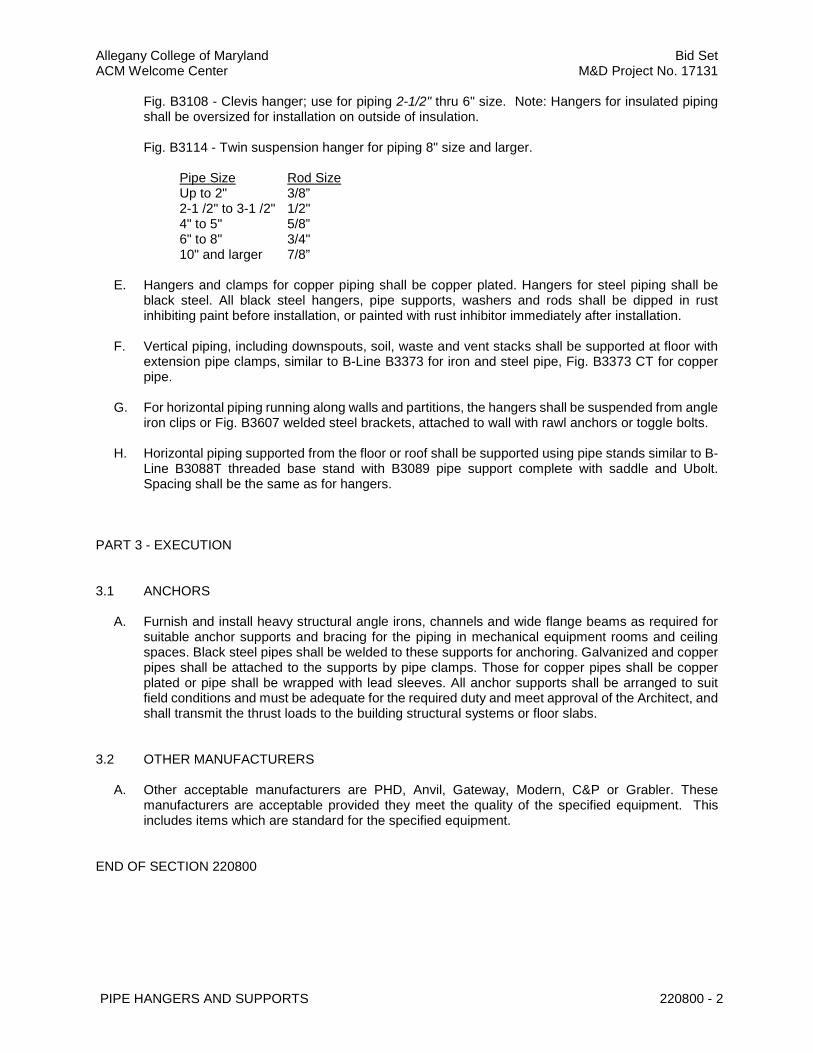
Fig. B3108 - Clevis hanger; use for piping 2-1/2" thru 6" size. Note: Hangers for insulated piping shall be oversized for installation on outside of insulation.
Fig. B3114 - Twin suspension hanger for piping 8" size and larger.
Pipe Size Rod Size Up to 2" 3/8” 2-1 /2" to 3-1 /2" 1/2" 4" to 5" 5/8” 6" to 8" 3/4" 10" and larger 7/8”
E. Hangers and clamps for copper piping shall be copper plated. Hangers for steel piping shall be
black steel. All black steel hangers, pipe supports, washers and rods shall be dipped in rust inhibiting paint before installation, or painted with rust inhibitor immediately after installation.
F. Vertical piping, including downspouts, soil, waste and vent stacks shall be supported at floor with
extension pipe clamps, similar to B-Line B3373 for iron and steel pipe, Fig. B3373 CT for copper pipe.
G. For horizontal piping running along walls and partitions, the hangers shall be suspended from angle
iron clips or Fig. B3607 welded steel brackets, attached to wall with rawl anchors or toggle bolts. H. Horizontal piping supported from the floor or roof shall be supported using pipe stands similar to B-
Line B3088T threaded base stand with B3089 pipe support complete with saddle and Ubolt. Spacing shall be the same as for hangers.
PART 3 - EXECUTION
3.1 ANCHORS
A. Furnish and install heavy structural angle irons, channels and wide flange beams as required for
suitable anchor supports and bracing for the piping in mechanical equipment rooms and ceiling spaces. Black steel pipes shall be welded to these supports for anchoring. Galvanized and copper pipes shall be attached to the supports by pipe clamps. Those for copper pipes shall be copper plated or pipe shall be wrapped with lead sleeves. All anchor supports shall be arranged to suit field conditions and must be adequate for the required duty and meet approval of the Architect, and shall transmit the thrust loads to the building structural systems or floor slabs.
3.2 OTHER MANUFACTURERS
A. Other acceptable manufacturers are PHD, Anvil, Gateway, Modern, C&P or Grabler. These
manufacturers are acceptable provided they meet the quality of the specified equipment. This includes items which are standard for the specified equipment.
END OF SECTION 220800

Allegany College of Maryland Bid Set ACM Welcome Center M&D Project No. 17131
VALVES AND ACCESSORIES 221000 - 1
SECTION 221000 - VALVES AND ACCESSORIES
PART 1 - GENERAL
1.1 SCOPE
A. Provide all valves shown, called for, or required for proper operation and servicing of all systems
and equipment included in this Division. Refer to Section 222200 for piping systems and specifications.
B. In addition to information in this specification section, refer to Section 222200 for additional
information regarding valves and accessories specifically for domestic water systems. C. All valves installed between basement level (and including) the booster pump discharge header
and the 15th shall be rated for a working pressure of 250 PSIG minimum. D. All valves from the 16th floor and higher shall be rated for a working pressure of 150 psig minimum.
PART 2 - PRODUCTS
2.1 DOMESTIC WATER SYSTEM AND DRAINAGE VALVES
A. Furnish and install all valves as indicated on the drawings, as specified below or as required. Valves
for all services shall be of one manufacturer. "Victaulic" for grooved piping systems and "Nibco Company" for flanged or soldered systems, whose figure numbers are used below, or other acceptable manufacturers as specified hereinafter.
B. Piping, valves, fittings, accessories and trim installed in domestic water systems in which there is
the potential for human consumption shall contain only materials that meet the "Reduction of Lead in Drinking Water Act" an amendment to the Safe Drinking Water Act. These materials shall be "Lead Free" in which they shall not contain more the 0.25% lead when used with respect to the wetted surfaces of the material.
C. All valves 2" and smaller which will be operated frequently, or will be used for throttling services,
shall be globe valves. Stop valves shall be gate valves. Ball valves may be used as stop valves in pipes 3" or less and shall be full port.
D. Valves 2" and less in the domestic hot water, hot water return and cold water systems shall be:
Steel Pipe Copper Tube
Gate Valves: Figure T-111/113 Figure S-113-LF Globe Valves: Figure T-211-Y N/A Check Valves: Figure T-413-W Figure S-413-Y-LF Ball Valves: Figure T-580-70 Figure S-685-80-LF
E. Valves larger than 2" shall be:
Gate Valves: Figure F-619 TI-8 / SI-8

Allegany College of Maryland Bid Set ACM Welcome Center M&D Project No. 17131
VALVES AND ACCESSORIES 221000 - 2
Globe Valves: Figure F-718-B T-235 / S-235 Check Valves: Figure F-918-B T-413 / S-413 Ball Valves: Figure F-510 S-580-70-66
F. Backwater valves shall be "Zurn" Z-1095-BC, disc type valve seat and rotating valve disc, and
bolted cover.
G. Backflow preventers shall be applied to all make-up water lines serving hydronic systems. Backflow preventers shall be installed in the fire protection system, domestic water system and all other areas as required by the local authority. Backflow preventers in the domestic water system and all make-up water systems shall be reduced pressure zone type equal to "Watts" Series LF909-Lead Free (for sizes 3/4" to 2") and "Watts" series 994-Lead Free (for sizes 2-1/2" to 10") complete with shut-off valves strainer and test ports. Provide an air gap fitting and pipe drain line to nearest floor drain. Backflow preventers for fire protection systems shall be double check assembly equal to "Watts" Series 774 complete with OS&Y valves, stainless steel construction and top access cover. All backflow preventers shall be installed and tested in accordance with the local authority. The Plumbing Contractor shall coordinate all requirements with other trades affected by his work.
H. Pressure reducing valves for lines 1/2" to 3" shall be equal to "Watts" Series LFN223B with Lead
Free brass construction rated for an in let pressure of 300 psi and an adjustable pressure range of 25-75 psi.
I. Balancing valves 2-1 /2" to 12: with flanged fittings shall be equal to TA Hydronics balancing valves
with provision for connecting a portable differential (Ft. of Head) pressure meter. Each meter connection shall have pressure/temperature probes. The balancing valves shall be Y -Pattern globe style design and with ductile iron body all other wetted parts of nonferrous, pressure die-cast copper alloy. Each valve shall provide three functions: (1) preciSion flow measurement, (2) precision flow balancing, (3) shut-off feature, eliminating the need of an additional isolation valve. These valves shall have eight, twelve or sixteen 3600 adjustment turns of the handwheel for maximum setting with hidden memory feature to program the valve with precision tamper-proof balancing setting. Handwheel shall have digital readout. NIBCO G737 with equal provisions is also acceptable.
J. Balancing valves 1/2" to 2" shall be equal to TA Hydronics Series 786/787/787-U STAD/STAS style
balancing valves with portable differential (Ft. of Head) pressure meter or NIBCO T1710 or S1710. Each meter connection shall have pressure/temperature probes. The balancing valves shall be V-pattern globe style design and all metal parts of nonferrous, pressure die cast, nonporous copper alloy. Each valve can be installed in any direction without affecting flow measurement and shall provide four functions: (1) precise flow measurement, (2) precise flow balancing, (3) positive shut-off with no drip seat. Eliminating the need of an additional isolation valve, (4) drain connection using 3/4" NPT hose end thread. These valves shall have four 3600 adjustment turns of handwheel for precise setting with hidden memory feature to program the valve with precision tamper-proof balancing setting. Handwheel shall have digital readout.
K. Hose end drain valves shall be provided at the bottom of all risers, and elsewhere where necessary
to permit draining the systems or portions of the system.
L. Furnish and install hose bibs as indicated on drawings, or as specified herein. Small hose bibs shall be "Woodford" Model 24, anti-siphoning. For non-freeze applications furnish "Woodford" Model 27.
2.2 ACCESSORIES A. Thermometers shall be "H.O. Trerice" V80445 4-1 /2" dial 300 F - 2400 F, stainless steel, with
wells, and stem length as required to clear insulation. B. Pressure gauges shall be "H.O. Trerice" 600CB, or approved equal 4-1 /2" cast aluminum case
and chrome ring, and adjustable dial, with 735 needle valve for snubber. Pressure ranges as necessary for the system.

Allegany College of Maryland Bid Set ACM Welcome Center M&D Project No. 17131
VALVES AND ACCESSORIES 221000 - 3
C. Manual air vents shall be installed at all high points in the piping systems. D. Automatic air vents shall be "Watts" Series DuoVent suitable for a maximum working temperature
of 240°F and a maximum working pressure of 150 psig. E. All gauge cocks shall be "H.O. Trerice" Model 735 quality standard needle valves, and shall serve
as snubbers. F. Temperature and pressure relief valves for domestic water heaters and hot water supply tanks shall
be equal to "Watts" LF40XL and shall be properly sized based on the fuel input rating of the heater. The valve body shall be constructed of Lead Free brass and have a tamper-resistant bonnet screw. These valves shall be ASME and CSA rated.
PART 3 - EXECUTION
3.1 NOTE
A. Where piping is insulated, ball valves shall be equipped with 2" extended handles of non-thermal
conductive material equal to "NIB-seal". Also, provide a protective sleeve that allows operation of the valve without breaking the vapor seal or disturbing the insulation. Memory stops, which are fully adjustable after insulation is applied, shall be included.
B. Provide balancing valves on all domestic hot water re-circulating branch lines and as indicated on
the drawings to properly balance the entire system. C. All valve sizes shall be the same as the line size in which they are being installed unless otherwise
indicated. D. Pressure-reducing valves shall be installed at the indicated locations to maintain the user water
pressure at 80 psi or less, unless otherwise directed. A bypass with a globe valve shall be installed around the pressure-reducing valve. Shut off valves shall be installed on the inlet and outlet size of the pressure-reducing valve for easy removal for maintenance.
E. Valves installed on the domestic cold water system on, and including, the booster pump discharge
hearer and the 5th floor shall be rated for a working pressure of 250 psig.
3.2 OTHER MANUFACTURERS
A. Other acceptable manufacturers are Crane, Fairbanks, Jenkins, Lunkenheimer, Reading Pratt and
Cady or DeZurick for valves. Other acceptable manufacturers for specialties are Victaulic, Bell and Gossett, Armstrong, Thrush, Dwyer, Ames or Febco. These manufacturers are acceptable provided they meet the quality of the specified equipment. This includes items which are standard for the specified equipment.
END OF SECTION 221000

Allegany College of Maryland Bid Set ACM Welcome Center M&D Project No. 17131
INSULATION 221800 - 1
SECTION 221800 - INSULATION
PART 1 - GENERAL
1.1 SCOPE
A. Provide and install insulation as hereinafter specified for all piping and duct systems where
indicated.
1.2 FIRE SAFETY CONSIDERATIONS
A. All insulating materials used shall have Flame Spread Rating not exceeding 25, and a Smoke Developed Rating not to exceed 50. These ratings shall be determined and verified by ASTM E-84, NFPA 255, or UL 723.
B. Insulation using "Salts" to impart fire safety will not be accepted.
1.3 MANUFACTURERS
A. Insulation shall be by one manufacturer, either "Owens-Corning" or other manufacturers as
specified hereinafter
PART 2 - PRODUCTS
2.1 PIPING INSULATION
A. Concealed piping (in furred spaces and above ceilings) shall be insulated with "Owens Corning"
SSL-11 preformed fiberglass pipe insulation with all service jacket and self-sealing lap. (Thickness as scheduled below).
B. Exposed piping (in boiler room and fan rooms, and where visible) shall be insulated same as above. C. Insulation thicknesses shall be:
1. Domestic Water (Cold, Hot, and Recirculating):
a. 1" thickness for all water lines up to 3" in size. b. 1-1 /2" thickness for all lines 4" and over. c. Armaflex, as manufactured by Armstrong, of equal thickness and 'K' value may be
used in lieu of fiberglass. 2. Air conditioning condensate and Horizontal Storm water drain lines:
a. 1" thickness for all sizes. D. "Zeston" or approved equal jacket system shall be used for all valves, fittings, and joints in the
piping system, with insulation.
PART 3 - EXECUTION

Allegany College of Maryland Bid Set ACM Welcome Center M&D Project No. 17131
INSULATION 221800 - 2
3.1 INSTALLATION
A. All insulation shall be applied on clean, dry surfaces only. B. All insulation shall be continuous thru wall and ceiling openings, and sleeves. C. Insulation on all cold surfaces, where vapor barrier jackets are used, will be applied with continuous,
unbroken vapor seal. Hangers, supports, anchors, etc. that are secured directly to cold surfaces must be adequately insulated and vapor-sealed to prevent condensation.
D. Inserts shall be installed at outsize hangers. Inserts between the pipe and pipe hangers shall
consist of rigid pipe insulation of equal thickness to the adjoining insulation, and shall be provided with vapor barrier where required. Insulation inserts shall be B-Line or equal and shall not be less than the following lengths:
1/2" to 2-1/2" pipe size: 6” long 3" to 6" pipe size: 9” long 8" to 10" pipe size: 12” long 12" to over pipe size: 18” long
E. Metal shields shall be applied between hangers or supports and the pipe insulation. Shields shall
be formed to fit the insulation and shall extend up to the centerline of the pipe and length specified for the insulation hanger inserts. Metal shields shall be B-Line or equal.
F. Specified adhesives, mastics and coatings shall be applied at the manufacturer's recommended
minimum coverage per gallon. G. Exposed insulated vertical pipe shall be protected to eight feet (8') above floor with 22 gauge
smooth paintable riveted steel jacket. Vertical piping in equipment rooms do not require metal jackets.
3.2 OTHER MANUFACTURERS
A. Other acceptable manufacturers are Johns Mannville, Gustin Bacon, PPG and Knauf. These
manufacturers are acceptable provided they meet the quality of the specified material. This includes the items which are standard for the specified material.
END OF SECTION 221800

Allegany College of Maryland Bid Set ACM Welcome Center M&D Project No. 17131
DOMESTIC WATER PIPING 222200 - 1
SECTION 22.2200 - DOMESTIC WATER PIPING
PART 1 - GENERAL
1.1 SCOPE
A. Furnish and install all labor, materials and equipment required to provide a complete cold, hot and
re-circulating domestic water piping system as shown on the drawings and specified herein. B. Pipes, valves, fittings and fixtures installed in domestic water shall contain only materials that meet
the requirement of Maryland's House Bill H.B. 372-2010 for Lead Free Law. "Leadfree" means: (1) Containing not more than 0.2% lead for solder and flux; (2) containing not more than 8% lead by dry weight for pipes and pipe fittings; and (3) containing a percentage of lead for plumbing fittings and fixtures that is in compliance with standards established under 42 U.S.CA § 300g-6(e) of The Federal Safe Drinking Water Act; and (4) containing not more than a weighted average lead content of 0.25% for the wetted surfaces of a pipe, pipe fitting, plumbing fitting, or fixture.
PART 2 - PRODUCTS
2.1 PIPING AND FITTINGS
A. All hot water and cold water piping above grade shall be of Type L hard drawn copper water tube,
ASTM B-88-49, with solder type wrought copper fittings ASA A40.3, or standard weight galvanized steel pipe with galvanized malleable iron fittings. Brass solder-joint valves shall be used with copper tubing. Isolating fittings shall be used to prevent metal-to-metal contact between steel and copper pipe. Type L copper must be used for pipe 3" and smaller, above 3" galvanized steel may be used. Solder for copper pipe shall be 95-5 tin-antimony, non-lead bearing. Fittings used in the Victaulic Pressfit system shall be Vic-Press 304, precision cold drawn austenitic 304 stainless steel. Pipe 2" and smaller shall be ASTM A312 .049 wall, 304SS, Pressfit Certified.
B. For domestic water piping larger than 3": The Victaulic or equal grooved systems may be used in
lieu of threaded or soldered system for above-ground water piping not exceeding 230°F. In galvanized systems, all fittings must be galvanized. In copper systems, all fittings must be wrought copper or bronze sand casting per ASTM B584-87 copper alloy CDA 836. Gaskets supplied with grooved couplings shall be pre-lubricated by the manufacturer with Vic-Plus dry lubricant or equal. Grooved-End-Tube Couplings: Copper-tube dimensions and design similar to AWWA C606. Include ferrous housing sections cast with offsetting, angle-pattern bolt pads, coated with copper-colored enamel, Grade "EHP" EPDM gasket suitable for hot water (UL listed and NSF-61 certified for hot and cold domestic water service), and bolts and nuts. Coupling shall be "installation ready" stab-on design for direct 'stab' installation on to roll grooved copper tube without prior field disassembly and no loose parts. Victaulic Style 607 QuickVic ™
C. Furnish and install water hammer arrestors in the water piping, in horizontal runs as indicated on
drawings or as required to prevent noise or injury to the piping system resulting from water hammer. The water hammer arrestors shall be Wilkins model 1250XL-Lead Free quality standard. The unit shall consist of copper casing and air-charged with acetal polypropylene piston. As a minimum, the following devices shall be served by shock absorbers: 1. Flush valve water closets 2. Each battery of lavatories 3. Showers in batteries of 2 or more

Allegany College of Maryland Bid Set ACM Welcome Center M&D Project No. 17131
DOMESTIC WATER PIPING 222200 - 2
4. Washing machine 5. The top of all water risers 6. Quick closing valves
2.2 SYSTEM ACCESSORIES
A. Each of the various mains, branches and connections of the hot and cold water distributing piping
systems shall be provided with a shut-off valve. These valves shall be placed at points necessary for the proper control and isolation of the system. Each piece of equipment or appliance shall be separately valved and provided with sufficient unions that service can be shut off and the piece of equipment or appliance removed, if desired, without disturbing the piping system. Valves shall be located so as to be easily accessible to the operator.
B. Provide for expansion of all piping subject to temperature changes. In general, this shall be
accomplished by swings, bends or loops.
PART 3 - EXECUTION
3.1 MISCELLANEOUS ITEMS
A. Thermometers shall be installed where shown or specified and shall be 4-1 /2" dial type, range 300
to 2400 F., "H.O. Trerice" V80445 quality standard. B. Pressure gauges shall be heavy-duty type with cast aluminum case and chrome ring, 4-1/2" size,
range 0 to 160 Ibs., "H.O Trerice" 600CB. Provide one on water line where it enters building and elsewhere as indicated.
C. Unless otherwise directed, piping subject to damage from freezing shall be heat traced using
"Raychem XL" self-regulating heat tracing system. The heat tracing shall be applied directly to the pipe, valves and fittings underneath any insulation or pipe jacketing specified under other sections of Division 15. The contractor shall coordinate all electrical requirements with Division 16. The heat tracing shall be sized and installed in accordance with the manufacturer’s instructions.
D. Expansion tanks for domestic hot water systems shall be manufactured by "Amtrol" model "Therm-
X-Trol" or approved equal, with NSF61 approval, Lead Free as described above, molded propylene liner and stainless steel connectors. The tank shall be sized in accordance with the schedule shown on the drawings. All domestic hot water heating systems shall be equipped with a thermal expansion tank. The expansion tank shall be connected to the cold water service to the water heating plant, downstream of any check valves or backflow preventers.
3.2 STERILIZATION
A. After final testing for leaks, all new potable water lines shall be thoroughly flushed to remove foreign
material. Before placing the systems in service, Contractor shall engage a qualified service organization, ARC Water Treatment Company or approved equal, to sterilize the new water lines in accordance with the following procedure:
B. Through a 3/4" hose connection in the main entering the building, pump in sufficient sodium
hypochlorite to produce a free available chlorine residual of not less than 200 PPM. Contractor shall provide plumbing connections and power for pumping chlorine into the system.

Allegany College of Maryland Bid Set ACM Welcome Center M&D Project No. 17131
DOMESTIC WATER PIPING 222200 - 3
C. Proceed upstream from the point of chlorine application opening all faucets and taps until chlorine is detected. Close faucets and taps when chlorine is evident.
D. When chlorinated water has been brought to every faucet and tap with a minimum concentration
of 200 PPM chlorine, retain this water in the system for three (3) hours as required by the local Health Department.
E. At the end of the retention period, no less than 100 PPM of chlorine shall be present at the extreme
end of the system. F. Proceed to open all faucets and taps and thoroughly flush all new lines until the chlorine residual
in the water is less 1.0 PPM. G. Obtain representative water samples from the system for analysis by a certified bacteriological
laboratory. H. If all samples tested for coliform organisms are negative, a letter and laboratory reports shall be
submitted by the service organization to the Contractor, certifying successful completion of the sterilization.
I. If any samples tested indicate the presence of coliform organisms, the entire sterilization procedure
shall be repeated.
END OF SECTION 222200

Allegany College of Maryland Bid Set ACM Welcome Center M&D Project No. 17131
DOMESTIC WATER PIPING 222200 - 4
THIS PAGE WAS LEFT INTENTIONALLY BLANK

Allegany College of Maryland Bid Set ACM Welcome Center M&D Project No. 17131
DRAINAGE PIPING
224020 - 1
SECTION 224020 - DRAINAGE PIPING
PART 1 - GENERAL
1.1 SCOPE
A. Furnish and install all labor and materials required to provide a complete plumbing system,
including sanitary, drain, vent and storm water piping, as shown on the drawings and specified herein.
B. Rules, regulations and standard of the respective regulating authorities shall be followed whenever
applicable. This Contractor shall include in his bid price, the cost of all materials or labor required, and all charges or fees assessed by the above authorities order that the work shall comply with their requirements.
PART 2 - PRODUCTS
2.1 DRAINAGE PIPING MATERIALS
A. All drain piping above ground shall be service weight cast iron hub and spigot pipe and fittings, cast
iron no HUB or standard weight galvanized steel pipe, with galvanized recessed drainage fittings. Joints shall be made up with extra heavy no-hub bands and appropriate materials in an approved manner.
B. All drain piping in the ground inside and outside the building shall be service weight cast iron hub
and spigot type, pipe and fittings standard ASTM A 74. C. All cast iron pipe and fittings shall conform to the requirements of CISPI 301, ASTM A 888 or ASTM
A 74. D. Cast iron pipe and fittings shall be marked with the collective trademark of the Cast Iron Soil Pipe
Institute (CISPI) or receive prior approval from the Engineer.
PART 3 - EXECUTION
3.1 MANNER OF INSTALLATION
A. All materials and equipment shall be new and of the quality specified, and shall be installed in a
neat and workmanlike manner by competent specialists for each trade. The installation of any materials and equipment not meeting these standards may be condemned by the Architect and shall be removed and reinstalled at no cost to the Owner.
B. Materials, equipment fixtures, and fittings shall be properly protected during installation and all
outlets, tappings and openings in the work shall be kept temporarily closed, with proper capping methods approved by the Architect.
C. All piping shall be sloped, free of traps and unnecessary bends and arranged to conform to the building requirements, to maintain proper headroom, and to suit the necessities of clearance for

Allegany College of Maryland Bid Set ACM Welcome Center M&D Project No. 17131
DRAINAGE PIPING
224020 - 2
other mechanical work. This Contractor shall fully inform himself regarding all furred ceilings, pipe spaces, walls, etc., in which his pipes are to run and see to it that his pipes do not require more than available furred space. If, for any reason, changes in location of piping are made, Contractor shall make sure his pipes are not run in areas which are to be clear of pipes.
D. All horizontal drainage piping 3" and larger shall run at a uniform grade of not less than 1/8" per
foot; piping less than 3" at no less than 1/4" per foot. All vent piping shall be graded to drain back to drain pipe by gravity.
E. Cast iron piping shall be installed in accordance with the Cast Iron Soil Pipe Institute Standards.
END OF SECTION 224020
Allegany College of Maryland Bid Set ACM Welcome Center M&D Project No. 17131
CLEANOUTS AND DRAINS 224030 - 1
SECTION 224030 - CLEANOUTS AND DRAINS
PART 1 - GENERAL
1.1 SCOPE
A. Furnish and install all cleanouts and drains where shown on the drawings and as specified herein.
PART 2 - PRODUCTS
2.1 CLEANOUTS
A. Cleanouts shall be provided at ends of runs, at all changes of direction, and near the base of each
vertical soil, waste, or drain pipe. Cleanouts shall be placed as shown on drawings or in accordance with applicable authority, but no more than seventy-five (75) feet apart inside the building unless the conditions require them at closer intervals. Cleanouts at the base of vertical pipes shall be placed in a fitting just above the floor. Cleanouts shall consist of 'Y' branches of 1/4 bends the full size of the line for piping 4" and smaller, and 4" and larger pipes. Cleanouts in horizontal lines shall be extended to floor level or grade as necessary. All cleanouts shall be Zurn "Supremo" numbers as listed below, or other manufacturers as specified herein.
• All exposed horizontal piping Z-1440 • Concealed in finished walls Z-1441 • Below concrete floor (No finish) Z-1449 • Below finished floors (Carpeted) ZN-1400-CM • Below fin ished floors (Tile) ZN-1400-X or TX • Base of concealed vertical pipes Z-1446 • Outside the building Z-1449
B. All clean outs shall consist of cast iron ferrules with tapered shoulder brass plugs sealed against a
lead seat. All plugs in horizontal piping shall be heavy-duty type.
2.2 DRAINS
A. Furnish and install all floor and area drains as shown on the drawings and/or as described below.
Roof drains shall be furnished, installed, and connected under this Division. Roof drains shall be installed to elevations approved by the Roofing Contractor.
B. Drains shall be "Zurn" or other manufacturers as specified herein. C. Roof drains shall be "Zurn" ZC-100 ERC with galvanized cast iron dome with extension, roof sump
receiver and under deck clamp. Provide bronze mesh screen over dome. D. All floor drains not otherwise specified herein, shall be "Zurn" Z-540. Funnel drains shall be "Zurn"
ZN-415 with Type E strainer. Drains in plenums shall have deep seal traps. E. Floor drains in the toilet rooms shall be ZN-415 with polished nickel bronze type H, 6" diameter
adjustable strainer and clamping collar. Floor drains in finished areas shall be similar with suitable strainer.

Allegany College of Maryland Bid Set ACM Welcome Center M&D Project No. 17131
CLEANOUTS AND DRAINS 224030 - 2
F. All floor drains connected to storm water system shall have P traps unless otherwise indicated. All traps on floor drains connecting to the sanitary sewer system shall have P traps and priming connections and water supply connections. Where possible, priming lines shall be taken from vertical flush pipes of water closets.
PART 3 - EXECUTION
3.1 INSTALLATION
A. Final elevations of all drains and cleanouts installed in the floor shall be carefully checked. B. Materials, equipment fixtures, and fittings shall be properly protected during installation and
all outlets, tappings and openings in the work shall be kept temporarily closed, with proper capping methods approved by the Architect.
C. All piping shall be sloped, free of traps and unnecessary bends and arranged to conform
to the building requirements, to maintain proper headroom, and to suit the necessities of clearance for other mechanical work. This Contractor shall fully inform himself regarding all furred ceilings, pipe spaces, walls, etc., in which his pipes are to run and see to it that his pipes do not require more than available furred space. If, for any reason, changes in location of piping are made, Contractor shall make sure his pipes are not run in areas which are to be clear of pipes.
D. All horizontal drainage piping 3" and larger shall run at a uniform grade of not less than
1/8" per foot; piping less than 3" at no less than 1/4" per foot. All vent piping shall be graded to drain back to drain pipe by gravity.
E. Cast iron piping shall be installed in accordance with the Cast Iron Soil Pipe Institute
Standards.
3.2 OTHER MANUFACTURERS
A. Other acceptable manufacturers are Josam, J.R. Smith or Wade. These manufacturers are
acceptable provided they meet the quality of the specified equipment. This includes items which are standard for the specified equipment.
END OF SECTION 224030

Allegany College of Maryland Bid Set ACM Welcome Center M&D Project No. 17131
PLUMBING FIXTURES 224065 - 1
SECTION 224065 - PLUMBING FIXTURES
PART 1 - GENERAL
1.1 SCOPE
A. Furnish and install the plumbing fixtures shown and specified on the drawings, in accordance with
the requirements set forth herein. PART 2 - PRODUCTS
2.1 PLUMBING FIXTURES
A. All fixtures shall be complete with all required trim, supports supplied, stop valves, cast brass traps,
etc. All porcelain enamel shall be acid resisting. Fixtures shall be as specified on drawings or by approved manufacturers as specified hereinafter. All exposed metal shall be chrome plated.
B. All plumbing fixtures with wetted surfaces using potable water shall be NSF-61 certified for low –
lead content as required per the latest Safe Drinking Water Act and amendments.
PART 3 - EXECUTION
3.1 INSTALLATION
A. Where fixtures are set against glazed tile surfaces, the back edges shall be ground to make as tight
a fit as possible. The seam between fixture and wall shall be caulked with clear silicone sanitary sealant.
B. Floor outlet fixtures shall rest firmly and evenly on floors and shall be set on floor flanges with ring
gaskets. C. Where fixtures are mounted on uneven masonry walls, the wall behind the fixture shall be ground
smooth and the fixture installed flush and caulked. D. Traps and supplies of ADA compliant fixtures shall be covered with soft factory-manufactured
protective covers.
3.2 CLEANING
A. During construction, plumbing fixtures shall not be put in use, and shall be boarded over to prevent
their use by construction personnel. B. Prior to the completion of the work, all plumbing fixtures, fittings, and exposed piping shall be
thoroughly cleaned and polished. 3.3 EQUIPMENT MANUFACTURERS
Allegany College of Maryland Bid Set ACM Welcome Center M&D Project No. 17131
PLUMBING FIXTURES 224065 - 2
A. Where a fixture is specified as American Standard, Kohler, Eljer, Crane or Zurn, the offered fixture
shall be this specified fixture or one of those named herein. B. Where a fixture is specified as Elkay, Just or Advance, the offered fixture shall be the specified
fixture or one of those named herein. C. Where a drinking fountain/water cooler is specified as Elkay, Halsey Taylor, Oasis or Sunroc, the
offered fixture shall be the specified fixture or one of those named herein. D. The manufacturers named herein are acceptable provided they meet the quality of the specified
equipment. This includes items which are standard for the specified equipment.
3.4 PLUMBING FIXTURE TRIM
A. Plumbing fixture trim refers to faucets, traps, supplies, strainers, etc. B. Plumbing fixture trim which is offered for approval shall be the specified trim or an equal in
performance and construction. Equal construction requires that the materials used in construction are similar, (i.e. where heavy brass or stainless steel, etc. is part of the construction of the specified item, the offered item shall be the same).
END OF SECTION 224065