all mode transceiver i746pro
TRANSCRIPT

2001 NEW
HF/VHF ALL MODE TRANSCEIVER
i746PRO
INSTRUCTION MANUAL
This device complies with Part 15 of the FCC rules. Operation is sub-ject to the following two conditions: (1) This device may not causeharmful interference, and (2) this device must accept any interferencereceived, including interference that may cause undesired operation.
IC-746PRO.qxd 02.4.2 11:30 Page 1

i
2001 NEW 2001 NEW
FOREWORD
We understand that you have a choice of many differ-ent radios in the market place. We want to take a cou-ple of moments of your time to thank you for makingthe IC-746PRO your radio of choice, and hope youagree with Icom’s philosophy of “technology first”.Manyhours of research and development went into the de-sign of your IC-746PRO.
Rather than completely redesigning all areas to createa new radio, the engineering team at Icom decided tofollow in the footsteps of the IC-746 (one of the bestvalue transceivers in the marketplace) with the new“PRO.” Focused on real world improvements compiledover the last few years from letters, phone calls, E-Mails and newsgroup postings, the engineering teamat Icom is proud to say “many of these changes werecompiled from a list of suggestions from you, the ama-teur radio operator!”
FEATURES•32-bit Floating point DSP and 24-bit AD/DA converter
•DSP IF Filter creates 102 types of filter
•All mode capability covering 160–2 m
•100 Watt continuous duty cycle
•All mode digital modulation and demodulation
•RTTY demodulator and decoder
•Twin Pass Band Tuning
•RF speech compression with selectable pass band
•Microphone Equalizer
•SSB/CW synchronous tuning
IMPORTANT
READ THIS INSTRUCTION MANUALCAREFULLY before attempting to operate thetransceiver.
SAVE THIS INSTRUCTION MANUAL. Thismanual contains important safety and operating in-structions for the IC-746PRO.
EXPLICIT DEFINITIONS
PRECAUTIONS
RWARNING RF EXPOSURE! This device emitsRadio Frequency (RF) energy. Extreme caution should beobserved when operating this device. If you have anyquestions regarding RF exposure and safety standardsplease refer to the Federal Communications CommissionOffice of Engineering and Technology’s report on Evalu-ating Compliance with FCC Guidelines for Human RadioFrequency Electromagnetic Fields (OET Bulletin 65).
RWARNING HIGH VOLTAGE! NEVER attach anantenna or internal antenna connector during transmis-sion. This may result in an electrical shock or burn.
RNEVER apply AC to the [DC13.8V] jack on the trans-ceiver rear panel. This could cause a fire or ruin the trans-ceiver.
RNEVER apply more than 16 V DC, such as a 24 Vbattery, to the [DC13.8V] jack on the transceiver rearpanel. This could cause a fire or ruin the transceiver.
RNEVER let metal, wire or other objects touch any in-ternal part or connectors on the rear panel of the trans-ceiver. This may result in an electric shock.
NEVER expose the transceiver to rain, snow or any liquids.
AVOID using or placing the transceiver in areas with tem-peratures below –10°C (+14°F) or above +60°C (+140°F).Be aware that temperatures on a vehicle’s dashboard canexceed 80°C (+176°F), resulting in permanent damage tothe transceiver if left there for extended periods.
AVOID placing the transceiver in excessively dusty envi-ronments or in direct sunlight.
AVOID placing the transceiver against walls or puttinganything on top of the transceiver. This will obstruct heatdissipation.
Place unit in a secure place to avoid inadvertent use bychildren.
During mobile operation, DO NOT operate the transceiverwithout running the vehicle’s engine. When the trans-ceiver’s power is ON and your vehicle’s engine is OFF,the vehicle’s battery will soon become exhausted.
Make sure the transceiver power is OFF before startingthe vehicle. This will avoid possible damage to the trans-ceiver by ignition voltage spikes.
During maritime mobile operation, keep the transceiverand microphone as far away as possible from the magneticnavigation compass to prevent erroneous indications.
BE CAREFUL! The heatsink will become hot when oper-ating the transceiver continuously for long periods.
BE CAREFUL! If a linear amplifier is connected, set thetransceiver’s RF output power to less than the linear am-plifier’s maximum input level, otherwise, the linear ampli-fier will be damaged.
Use Icom microphones only (supplied or optional). Othermanufacturer’s microphones have different pin assign-ments, and connection to the IC-746PRO may damagethe transceiver.
WORD DEFINITION
RRWARNINGPersonal injury, fire hazard or electricshock may occur.
CAUTION Equipment damage may occur.
NOTEIf disregarded, inconvenience only. Norisk or personal injury, fire or electricshock.
IC-746PRO.qxd 02.4.2 11:30 Page 2

ii
SUPPLIED ACCESSORIESThe transceiver comes with the following accessories.
Qty.q DC power cable (OPC-025D) ............................ 1w Hand microphone (HM-36) ................................ 1e Spare fuses (FGB 30 A) .................................... 2r Spare fuse (FGB 5 A) ........................................ 1t CW keyer plug (AP-330) .................................... 1
TABLE OF CONTENTS
q w
e r t
FOREWORD ........................................ iIMPORTANT ........................................ iEXPLICIT DEFINITIONS ..................... iPRECAUTIONS ................................... iTABLE OF CONTENTS ...................... ii
QUICK REFERENCE GUIDE ........ I–X Installation ....................................... I Operation ....................................... III Your first contact ........................... IV Ready to call CQ? ......................... IX
1 PANEL DESCRIPTION ........... 1–12 Front panel ..................................... 1 Rear panel ...................................... 7 LCD display .................................... 9 Multi function switches .................. 11 Microphone (HM-36) .................... 12
2 INSTALLATION ANDCONNECTIONS ................... 13–17 Unpacking .................................... 13 Selecting a location ...................... 13 Grounding ..................................... 13 Antenna connection ...................... 13 Required connections ................... 14 Advanced connections ................. 15 Power supply connections ............ 16 Linear amplifier connections ......... 17 External antenna tuner
connections .................................. 17
3 BASIC OPERATION ............. 18–25 When first applying power
(CPU resetting) ............................. 18 Initial settings ................................ 18 Selecting an operating band ........ 19 Selecting VFO/memory mode ...... 20 VFO operation .............................. 20 Frequency setting ......................... 21 Operating mode selection ............ 23 Volume setting .............................. 23 Squelch and receive (RF)
sensitivity ...................................... 24 Basic transmit operation ............... 25
4 RECEIVE AND TRANSMIT .. 26–46 Operating SSB ............................. 26 Operating CW ............................... 27
Electronic keyer functions ............ 29 Operating RTTY (FSK) ................. 35 RTTY functions ............................. 36 Operating AM ............................... 40 Operating FM ............................... 41 Repeater operation ....................... 44
5 FUNCTIONS FOR RECEIVE........................................... 47–54
Simple band scope ....................... 47 Preamp/Attenuator ....................... 48 RIT function .................................. 48 AGC function ................................ 49 IF filter selection ........................... 50 IF (DSP) filter shape ..................... 51 Noise blanker ............................... 51 Meter peak hold function .............. 51 Twin PBT operation ...................... 52 Noise reduction ............................ 53 Notch function .............................. 53 Dial lock function .......................... 53 Voice squelch control function ...... 54
6 FUNCTIONS FOR TRANSMIT ........................................... 55–61
VOX function ................................ 55 Break-in function .......................... 56 ∂TX function ................................ 57 Monitor function ............................ 57 Speech compressor ..................... 58 Transmit filter width selection ....... 58 Split frequency operation .............. 59 Quick split function ....................... 60 Measuring SWR ........................... 61
7 MEMORY OPERATION ........ 62–68 Memory channels ......................... 62 Memory channel selection ............ 62 Programming a memory ............... 63 Memory clearing ........................... 63 Selecting the call channel ............. 64 Programming the call channel ...... 64 Frequency transferring ................. 65 Programming scan edges ............ 66 Assigning memory names ............ 67 Memo pads ................................... 68
8 SCANS ................................. 69–74 Scan types .................................... 69 Preparation ................................... 69
Voice squelch control function ...... 70 Scan set mode ............................. 70 Programmed scan/Fine programmed
scan .............................................. 71 Memory scan operation ................ 72 Select memory scan ..................... 72 ∂F scan operation and Fine ∂F scan
...................................................... 73 Tone scan/DTCS code scan
operation ...................................... 74
9 ANTENNA TUNER OPERATION ............................................ 75–77
Antenna connection and selection 75 Antenna tuner operation ............... 76 Optional external tuner operation . 77
10 DATA COMMUNICATION ..... 78–80 Connections ................................. 78 Packet (AFSK) operation .............. 79 Adjusting the TNC output level ..... 80 Data transmission speed .............. 80
11 SET MODE ............................ 81–89 General set mode ......................... 81 Tone control set mode .................. 89
12 OPTION INSTALLATION ..... 90–91 Opening the transceiver’s case .... 90 UT-102 VOICE SYNTHESIZER UNIT ... 90 CR-338 HIGH STABILITY CRYSTAL UNIT
..................................................... 91
13 MAINTENANCE .................... 92–94 Trouble shooting ........................... 92 Fuse replacement ......................... 93 Tuning dial brake adjustment ....... 93 Resetting the CPU ........................ 94 Frequency calibration (approximate)
..................................................... 94
14 CONTROL COMMAND ......... 95–99 Remote jack (CI-V) information .... 95
15 SPECIFICATIONS ...................... 100
16 OPTIONS.................................... 101
Icom, Icom Inc. and the logo are registered trademarks of Icom Incorporated (Japan) in the United States, the United King-dom, Germany, France, Spain, Russia and/or other countries.
2001 NEWIC-746PRO.qxd 02.4.2 11:30 Page 3

I
QUICK REFERENCE GUIDE
2001 NEW
Installation1. Install a ground system for DC noise suppression
and RFI suppression2. Install your DC power supply3. Install lightning protection. This will help protect
more than your gear.
4. Install and connect an antenna system for the ap-propriate bands of operation
5. Connect other peripheral equipment. This includesmicrophones, headsets, TNC, amplifiers and anyother equipment necessary to make your shackcomplete.
Although your radio will operate by connecting the DCpower supply and antenna, it is necessary to have agood ground system in your shack. A ground connec-tion is the electrical contact between the common pointof an electrical or electronic system and the earth.
A good earth ground is necessary to prevent electricalshock, eliminate problems from RFI and DC noise.With more electronic devices being used today, it isalso important to reduce RFI and EMI. Although youmay not see interference in your shack, without agrounding system, your neighbors may experience in-terference. Even though many of these devices arePart 15, where they must accept interference fromtheir surrounding environment, it is best to eliminateas much of the possible interference from your shack.
If you do not have a grounding system for your shack,depending on the location of your shack, basement orground floor, a good ground system can be as simpleas a couple of ground rods driven 6 to 8 feet into thesoil. When installing your IC-746PRO to your ground-ing system, the shortest most direct connection is rec-ommended.
NOTE: There are many publications coveringproper grounding techniques. Check with your localdealer for more information and recommendations.
RWARNING!: NEVER ground station equip-ment or antennas to house gas lines. NEVER at-tach ground lines to plastic (pvc) pipe.
DD Some Symptoms if inadequate groundinga. Poor DC Ground60 Hz hum on the audio either Rx or Tx without theantenna connected.
If you feel a tingling sensation when you touch ametal surface. Surfaces such as the cover of yourradio or power supply.
b. Poor RF GroundWhile transmitting and you feel a tingling sensationwhen you touch a metal surface. Surfaces such asthe cover of your radio or power supply.
While transmitting, you experience interference toother electronic devices, such as the telephone,television or stereo audio systems.
The DC power supply is a device used to convert110/220 V AC, also know as Household current, to asteady source of 13.8 V DC.
The perfect match to your IC-746PRO is the PS-125.This compact switching power supply is the matchingpower supply for your IC-746PRO with a current rat-ing of 25 A continuous duty. This plug and play unitplugs into the DC jack located on the rear of the radio.
• If you are not using the PS-125:
Connect the supplied DC power cable (OPC-025D) tothe appropriate color coded terminals, then insert theDC connector into the DC jack located on the rear ofthe radio.
NOTE: Although the power supply current require-ment is quite low during receiving, this not the casewhen you transmit. With many electrical devices inthe shack, it is very important to verify the electricalcircuit is not overloaded.
30 A fusesAC cable
TransceiverACoutlet
A DC powersupply*
*13.8 V; at least 23 Acontinuous
Black _
Red+
to DC powersocket
SuppliedDC power cable
PS-125 DC powersocket
Transceiver
DC power cable
Connect to an AC outlet using the supplied AC cable.
1. Grounding your Shack
2. Installing your DC Power Supply
IC-746PRO.qxd 02.4.2 11:30 Page I

II
QUICK REFERENCE GUIDE
3. Installing lightning protectionAlthough you may not live in an area with high occur-rence for lightning storms, it is always wise to takeprecautions for lightning or static discharges. Properlightning protection not only offers protection to theham gear, but the shack and most importantly the op-erator.
NOTE: There are many publications coveringproper lightning protection, check with your localdealer for more information and recommendations.
Whether your IC-746PRO is your first radio or one ofmany, one of your key elements in a great shack isthe antenna system. There are three connections onthe back of your IC-746PRO, two for HF and 6 m andone for 2 m. If you are using one antenna for HF and6 m, for simplicity, connect the antenna coax to ANT1.
Your IC-746PRO is equipped with an internal antennatuner (ATU) for operation on 160–6 m. This ATU is de-signed to work with an unbalanced 50 Ω feedline. Thepurpose of the internal antenna tuner is to match theimpedance of your antenna system to as close to a50 Ω load as possible. This ATU will not operate witha long wire or ladder line (450 Ω or other balancedfeedlines). An external ATU such as the AH-4 wouldbe necessary for this kind of operation.
PL-259 CONNECTOR INSTALLATION EXAMPLE
30 mm ≈ 9⁄8 in 10 mm ≈ 3⁄8 in 1–2 mm ≈ 1⁄16 in
RWARNING: Although a mag mount antennaworks great on a vehicle, DO NOT use the IC-746PRO with this type of antenna.
CAUTION: Although your IC-746PRO has protec-tion to drop down power with a high SWR, thisdoes not completely protect the transceiver fromtransmission without an antenna. Make sure youhave an antenna connected whenever you trans-mit with your radio.
NOTE: There are many publications coveringproper antennas and their installation, check withyour local dealer for more information and recom-mendations.
30 mm
10 mm (soft solder)
10 mm
1–2 mm
solder solder
Softsolder
Coupling ring
Slide the coupling ring down. Strip the cable jacket and soft solder.
Slide the connector body on and solder it.
Screw the coupling ring onto the connector body.
Strip the cable as shown at left. Soft sol-der the center con-ductor.
q
w
e
r
Antenna SWREach antenna is tuned for a specified frequencyrange and SWR may be increased out-of-range.When the SWR is higher than approx. 2.0:1, thetransceiver’s power drops to protect the final tran-sistors. In this case, an antenna tuner is useful tomatch the transceiver and antenna. Low SWR al-lows full power for transmitting even when using theantenna tuner. The IC-746PRO has an SWR meterto monitor the antenna SWR continuously.
ANTENNA 1, 2[Example]: ANT1 for 1.8–18 MHz bands
ANT2 for 21–50 MHz bands
144 MHz ANTENNA
Connect a VHF (60–144 MHz)antenna; impedance: 50 Ω.
4. Installing your antenna system
IC-746PRO.qxd 02.4.2 11:31 Page II
III
QUICK REFERENCE GUIDE
2001 NEW 2001 NEW
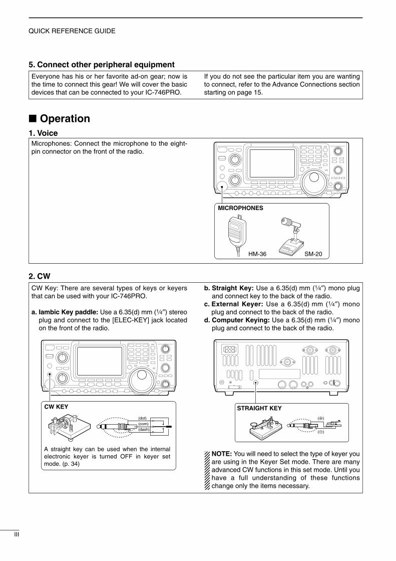
5. Connect other peripheral equipmentEveryone has his or her favorite ad-on gear; now isthe time to connect this gear! We will cover the basicdevices that can be connected to your IC-746PRO.
If you do not see the particular item you are wantingto connect, refer to the Advance Connections sectionstarting on page 15.
Microphones: Connect the microphone to the eight-pin connector on the front of the radio.
MICROPHONES
HM-36 SM-20
Operation1. Voice
CW Key: There are several types of keys or keyersthat can be used with your IC-746PRO.
a. Iambic Key paddle: Use a 6.35(d) mm (1⁄4″) stereoplug and connect to the [ELEC-KEY] jack locatedon the front of the radio.
b. Straight Key: Use a 6.35(d) mm (1⁄4″) mono plugand connect key to the back of the radio.
c. External Keyer: Use a 6.35(d) mm (1⁄4″) monoplug and connect to the back of the radio.
d. Computer Keying: Use a 6.35(d) mm (1⁄4″) monoplug and connect to the back of the radio.
NOTE: You will need to select the type of keyer youare using in the Keyer Set mode. There are manyadvanced CW functions in this set mode. Until youhave a full understanding of these functionschange only the items necessary.
STRAIGHT KEY
(+)
(_)
CW KEY
A straight key can be used when the internal electronic keyer is turned OFF in keyer set mode. (p. 34)
(dot)(com)(dash)
2. CW
IC-746PRO.qxd 02.4.2 11:31 Page III

IV
QUICK REFERENCE GUIDE
2001 NEW
3. Other convenient itemsHeadphones:A 6.35(d) mm (1⁄4″) mono jack for operation withoutusing the internal or external speakers. Perfect for op-eration without disturbing others in the room.
External Speaker:A 3.5(d) mm (1⁄8″) mono jack for operation with an ex-ternal speaker. (Input impedance: 8 Ω/Max. inputpower: 5 W)
EXTERNAL SPEAKER
SP-21 (optional)
HEADPHONES
1. Before powering up your radio, you may want tomake sure the following controls are set in the fol-lowing positions:
• [AF] : Commonly referred to as the vol-ume: fully counter clockwise.
• [NR] : The noise reduction control: fullycounter clockwise.
• [MIC GAIN] : The mic gain: fully counter clock-wise.
• [RF/SQL] : The control for the RF Gain andSquelch circuits: 12 o’clock.
• [CW PITCH] : The control for the CW pitch:12 o’clock.
• [KEY SPEED] : Internal CW Keyer Speed: fullycounter clockwise
• [NOTCH] : Control for the manual notch:12 o’clock
2. Resetting the CPU: Although you have purchaseda brand new radio, some settings may be changedfrom the factory defaults during the QC process. Soyour radio can start from Factory Defaults resettingthe CPU is necessary.
[POWER] [F-INP] [M-CL]
Your first contactNow you should have your IC-746PRO installed inyour shack, and like a kid on his birthday, you areprobably excited to get on the air. We would like totake you through a few basic operation steps to makeyour first “On The Air” an enjoyable experience.
DD Getting started
IC-746PRO.qxd 02.4.2 11:31 Page IV

V
QUICK REFERENCE GUIDE
2001 NEW 2001 NEW
DD Just listening
3. Verify proper antenna has been selected.
1. Select the desired band On your IC-746PRO, an easy way of changing bandsis by using the keypad located just above the tuningknob on the right hand side of the display. You will no-tice each switch has two sets of numbers; one set ofnumbers represents the band selection.
•Say you want to go to 20 meters or 14 MHz; youwould push the [14 5]. This will immediately changethe displayed operating frequency to the 20-meterband. By pushing [14 5] again, frequency pre-setsin the triple band stacking registers frequency can bedisplayed. For more details on this system refer top. 19.
GENE 50 0
21 7 24 8 28 9
14 510 4 18 6
3.5 21.8 1 7 3
144 ENT
Directly below the keypad is the tuning knob. This willallow you to dial in the frequency you want to oper-ate. You will notice the tuning speed [TS] is 10 Hz res-olution. Page 22 will instruct you on how to set thetuning speed [TS] for 1 Hz resolution.
NOTE: Although you can directly enter the fre-quency with the keypad, using the Band StackingRegister and the tuning knob is the most popularmethod of hoping around the bands. For more in-formation regarding the direct frequency entrymethod, refer to p. 22.
You IC-746PRO has three antenna connectors. Twofor HF and 6 m and a one for 2 m. The selection for2 m is automatic, where the HF and 6 m is user se-lectable for either one of the antenna jacks. For firsttime use, the antenna selector should show “ ” onthe display of your radio. Verify the antenna selectedon the display is the antenna port your antenna isconnected to.
Either “1” or “2” appears.*No indicator appears during 144 MHz operation.
Adjust this control to a comfortable audio level.
AF RF/SQL
No audio output Max. audio output
Decreases Increases
2. Tune to the desired frequency
4. Adjust audio output
IC-746PRO.qxd 02.4.2 11:31 Page V

VI
QUICK REFERENCE GUIDE
2001 NEW
DD What are you hearing? Stop and focus on what you are hearing. Do you heara lot of noise? Is the signal intelligible? Are you set upfor the right mode? How about the filters?
1. Verify mode
Your IC-746PRO has many features to reduce QRMand QRN from the desired signal.
a. Noise Reduction: The noise reduction system onyour IC-746PRO is part of the 32-bit DSP. This isused to reduce the hiss and QRM levels. To acti-vate, push the [NR] switch located just to the rightof the [PHONES] jack.
b. Adjusting the Noise Reduction: The noise re-duction is completely variable on how much of theDSP Noise Reduction is used [NR] level control lo-cated just above the [NR] switch.
Hint! How far you advance the NR control will determinehow much the noise can be effectively reduced.Turning the control too far clockwise may causesome distortion to occur on the received signal. TheNR control should only be turned as far clockwiseas is necessary. Use this control, along with RFgain, NB (noise blanker, if needed), and IF filters aswell, to minimize the effects of noise on the targetsignal.
Noise reduction ON
Noise reduction OFF
NR NOTCH
OFF
Decreases Increases
AGC DUP CMP TBW SCP
[NR] [NR]
Appears
Although your IC-746PRO will automatically selectUSB or LSB in the HF bands, it will not select any ofthe other modes. You will need to select the propermode whether CW, RTTY, AM or FM. Hint!
The Triple Band Stacking Register will memorizethe last three frequencies used in the band, as wellas the Mode, Filter, Tuner and AGC settings. Thismakes band hoping much easier.
SSB CW/RTTY AM/FM
2. Reducing interference
IC-746PRO.qxd 02.4.2 11:31 Page VI

VII
QUICK REFERENCE GUIDE
2001 NEW 2001 NEW
c. Notch: There are two notch systems on your IC-746PRO.
•Automatic: The automatic notch will track up to threeheterodynes. This is helpful for eliminating annoyingtransmitter “tune up” tones on any band, and to min-imize continuous tone “heterodynes” encountered onthe 40 meter phone bands at night, for example.Once selected an icon will appear “A NOTCH” onthe display.
•Manual: The Manual notch provides 70 dB of atten-uation to pin point an interfering signal. The 12 o’-clock position is on the operating frequency, turningthe Notch knob clockwise moves the notch up theband and counter clockwise will move the notchdown the band. Once selected an icon “NOTCH” willappear on the display.
NOTE: Your IC-746PRO is equipped with multipleAGC circuits. This allows the DSP to filter out inter-fering signals and QRM, while also taking this in-terference out of the AGC. Bottom line, this will ei-ther eliminate or greatly reduce the pumping of theAGC from the interfering signal.
AGC DUP CMP TBW SCP
[A/NOTCH] [NOTCH]
Notch function indicators
NR NOTCH
Low frequency High frequency
Hint! The Automatic Notch will not operate in the SSBdata, CW or RTTY modes.
d. Filters: Your IC-746PRO has an incredible IF DSPbased filter network with over 100 settings.
•Dial in your filters: By pushing [FILTER] for 1 sec.,you enter the filter set mode. This is where you areable set the three filter presets. Across the bottom ofthe display you will see the “BW” icon. The switch di-rectly below, along with the tuning dial, will be usedto select the changes you will make.
BW
• Filter set mode indication
Shows the selected filter and passband width.
BW
• Indication while setting
While pushing [F1 BW], rotate the tuning dial to setpassband width.
Reverses Appears
AGC DUP CMP TBW SCP
[FILTER]
The selected filter width is indicatedfor approx. 1 sec. when [FILTER] ispushed. Filter selection
IC-746PRO.qxd 02.4.2 11:31 Page VII

VIII
QUICK REFERENCE GUIDE
2001 NEW
d. Filters:— continued•On the fly adjustment: Once the adjustments havebeen made in the filter set mode, you can make onthe fly changes by using the Twin Pass Band Tuning,Twin PBT. You will be able to see the effects of theTwin PBT on the upper left hand side of the screen.
NOTE: The Twin PBT filters shift the two IF DSPfilters (See Diagrams below and right). This featureallows both an IF shift as well as a narrowing of thePass Band. Although you can narrow the passband by shifting the two filters, this does not nar-row both filters, thus the filter shape is not nar-rowed. You may hear some signal artifacts passthrough this filter adjustment.
PBT operation example
BW
• Filter set mode indication
Shows the selected filter and passband width.
BW
• Indication while PBT setting
Appears when passband is shifted.*By pushing [PBTC] for 1 sec., the shifted value returns to the default setting, and the “dot” disappears.
AGC DUP CMP TBW SCP
Passband width and shifting value areindicated while [TWIN PBT] is operated.
[TWIN PBT] control
[PBTC]
Appears when PBT is used.
One of “1,” “2” or “3” isdisplayed for selected filter
number indications.
interferenceinteferenceinterference desired signaldesired signal
pass band
IF center frequency
Center Passband Passband
IF center freq.
IF shift
IC-746PRO.qxd 02.4.2 11:31 Page VIII

IX
QUICK REFERENCE GUIDE
2001 NEW 2001 NEW
Once you have mastered your filter settings, one lastfeature to enable the most intelligible audio is the ac-tual audio tone you hear. You can adjust the equal-ization of your received audio ±5dB.
q Push [MENU] several times, or until M2 is shownon the display.
w Push [F4 TCN] for the Tone Control set mode.e Push the appropriate mode switch to adjust SSB,
AM or FM.r Push [F1 ≤] or [F2 ≥] to change to the desired
component.
[F1 ≤]
Tuning dial[MENU]
[F2 ≥] [F4 TCN]
3. RX Tone Control:
1. RX BassThis item adjusts the bass level of the receive audiotone from –5 dB to +5 dB in 1 dB steps.
RX Bass SSBO3
2. RX TrebleThis item adjusts the treble level of the receive audiotone from –5 dB to +5 dB in 1 dB steps.
RX Treble SSBO4
We hope these pointers have been helpful. Now youare ready for the “Ready to call CQ?”.
Ready to call CQ?
The 32-bit DSP in your IC-746PRO is capable of al-lowing you to selects transmit audio for phone modes.
POWER
TRANSMIT
PHONES
ELEC-KEY
MIC
NR A/NOTCH
TUNER ANT
HF/VHF TRANSCEIVER
NR NOTCH
AF
MIC GAIN RF PWR CW PITCH
F 1 F 2 F 3 F 4 F 5
XFC
MP-W
GENE 50 0
21 7 24 8 28 9
14 510 4 18 6
3.5 21.8 1 7 3
144 ENT
MP-R
TX RXLOCK
TWIN PBT
M-CH
RIT CLEAR∂TX
RIT/∂TX
TS
SPLIT
PBTC
F-INP
A/BV/M
MW
M-CL
KEY SPEED P.AMP/ATT NB VOX/BK-IN MONITOR CALL LOCK/SPCH
RF/SQL
i746PRO
MENU SSB CW/RTTY AM/FM FILTER
[NR]: Max. CCW [NOTCH]: Max. CCW
[AF]: Max. CCW
[TRANSMIT]: OFF
[MIC GAIN]: Max. CCW
[RF PWR]: Max. CCW [CW PITCH]: 12 o’clock
[RF/SQL]: 12 o’clock
[KEY SPEED]: Max. CCW
1. Setting up your transmit audio
2. Mic GainThe microphone gain is used for proper transmitaudio level for full output power.
IC-746PRO.qxd 02.4.2 11:31 Page IX

X
QUICK REFERENCE GUIDE
2001 NEW
Verify you have selected a clear frequencyand call out your CQ!
The capability of changing the pass band of yourtransmit audio, is at your finger tips. Regardless of thecondition of the speech compressor, you can adjust itby selecting the [F4 TBW].
You will find this located in the M1 menu. By pushing[F4 TBW] for 1 sec. you can select the TX audio bandpass.
There are three levels of audio passband width avail-able (Wide, Mid, and Nar).
TX Audio Passband widthsWide : 2.8 kHz ; Great Full AudioMid : 2.4 kHz ; Great for operators with
deep full voicesNar : 2.2 kHz ; Great for breaking through
pile ups
F 1 F 2 F 3 F 4 F 5
F 1 F 2 F 3 F 4 F 5
AGC DUP CMP TBW SCP
AGC DUP CMP TBW SCPTX BW=WIDE
Push [F4]
Push [F4] for 1 sec. to select the transmit filter width.
The selected transmit filter width is displayed for approx. 1 sec.
3. DSP TX Audio Pass Band
4. Microphone EqualizerAlthough these bandwidths are fixed, the MicrophoneTone Control will give you more audio control for yourvoice operation on SSB, AM, and FM modes. Your IC-746PRO is equipped with a very powerful equalizersystem with 121 possible combinations. This isachieved by using the separate bass and treble ad-justments. The default for both the Base and Trebleis at 0 dB.
Entering Microphone Tone Control set mode:
q Push [MENU] several times, or until M2 is shownon the display.
w Push [F4 TCN] for the Tone Control set mode.e Push the appropriate mode switch to adjust SSB,
AM, or FM.r Push [F1 ≤] or [F2 ≥] to change to the desired
component.
Hint! Voice patterns and audio characteristics vary witheach operator, therefore the [MIC GAIN], DSP TXAudio Pass Band and Microphone Tone Controlsettings will be different for each operator. Actual onair experimenting is necessary to get just the rightsound. Listen to your transmit audio with head-phones and the monitor function turned ON. It’salso best to test and adjust your audio on the air,while someone who knows what your real voicesounds like listens, and provides and opinion onyour audio quality.
[F1 ≤]
Tuning dial[MENU]
[F2 ≥] [F4 TCN]
1. TX BassThis item adjusts the bass level of the transmit audiotone from –5 dB to +5 dB in 1 dB steps.
TX Bass SSBO1
2. TX TrebleThis item adjusts the treble level of the transmit audiotone from –5 dB to +5 dB in 1 dB steps.
TX Treble SSBO2
IC-746PRO.qxd 02.4.2 11:31 Page X

1
1
PANEL DESCRIPTION
2001 NEW
Front panel
q POWER SWITCH [POWER]Push momentarily to turn power ON.
•Turn the optional DC power supply ON in advance.Push for 1 sec. to turn power OFF.
w TRANSMIT SWITCH [TRANSMIT]Selects transmitting or receiving.•The [TX] indicator lights red while transmitting and the[RX] indicator lights green when the squelch is open.
e HEADPHONE JACK [PHONES]Accepts headphones.•Output power: 5 mW with an 8 Ω load.•When headphones are connected, the internal speakeror connected external speaker does not function.
r ELECTRONIC KEYER JACK [ELEC-KEY] (p. 14)Accepts a paddle to activate the internal electronickeyer for CW operation.•Selection between the internal electronic keyer, bug-keyand straight key operation can be made in keyer setmode. (p. 34)
•A straight key jack is separately available on the rearpanel. See [KEY] on p. 7.
•Keyer polarity (dot and dash) can be reversed in keyerset mode. (p. 34)
•4-channel memory keyer is available for your conve-nience. (p. 30)
t MICROPHONE CONNECTOR [MIC]Accepts the supplied or an optional microphone.•See p. 101 for appropriate microphones.•See p. 12 for microphone connector information.
y RF GAIN CONTROL/SQUELCH CONTROL[RF/SQL] (outer control)Adjusts the RF gain and squelch threshold level.The squelch removes noise output from the speaker(closed condition) when no signal is received.•The squelch is particularly effective for FM. It is alsoavailable for other modes.
•12 to 1 o’clock position is recommended for any settingof the [RF/SQL] control.
•The control can be set as ‘Auto’ (RF gain control in SSB,CW and RTTY; squelch control in AM and FM) orsquelch control (RF gain is fixed at maximum) in setmode as follows. (p. 82)
•When setting as RF gain/squelch control
Recommended level
RF gain adjustablerange
Maximum RF gain
S-meter squelch
Noise squelch (FM mode)
Squelch is open.
MODE
SSB, CWRTTY
AM, FM
AUTO
RF GAIN
SQL
SQLSET MODE SETTING
SQL
SQL
RF GAIN + SQL
RF GAIN + SQL
RF GAIN + SQL
(dot)(com)(dash)
POWER
TRANSMIT
PHONES
ELEC-KEY
MIC
NR A/NOTCH
TUNER ANT
HF/VHF TRANSCEIVER
NR NOTCH
AF
MIC GAIN RF PWR CW PITCH
F 1 F 2 F 3 F 4 F 5
XFC
MP-W
GENE 50 0
21 7 24 8 28 9
14 510 4 18 6
3.5 21.8 1 7 3
144 ENT
MP-R
TX RXLOCK
TS
SPLIT
F-INP
A/B
KEY SPEED P.AMP/ATT NB VOX/BK-IN MONITOR CALL LOCK/SPCH
RF/SQL
i746PRO
MENU SSB CW/RTTY AM/FM FILTER
q
w
e
r
t
y u io !0 !1
!4!5!6!7 !3 !2
IC-746PRO.qxd 02.4.2 11:31 Page 1
2
1PANEL DESCRIPTION
•When functioning as RF gain control(Squelch is fixed open; SSB, CW, RTTY only)
•When functioning as squelch control(RF gain is fixed at maximum.)
While rotating the RF gain control, noise may beheard. This comes from the DSP unit and does notindicate an equipment malfunction.
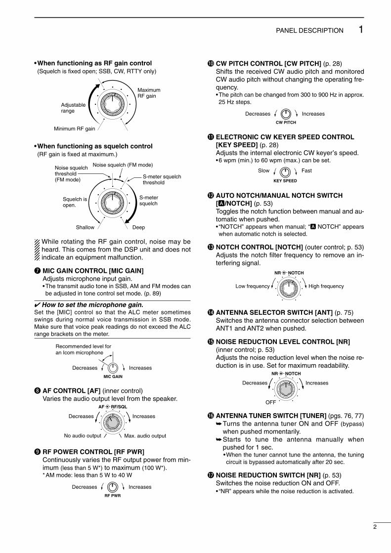
u MIC GAIN CONTROL [MIC GAIN]Adjusts microphone input gain.•The transmit audio tone in SSB, AM and FM modes canbe adjusted in tone control set mode. (p. 89)
How to set the microphone gain.Set the [MIC] control so that the ALC meter sometimesswings during normal voice transmission in SSB mode.Make sure that voice peak readings do not exceed the ALCrange brackets on the meter.
i AF CONTROL [AF] (inner control)Varies the audio output level from the speaker.
o RF POWER CONTROL [RF PWR] Continuously varies the RF output power from min-imum (less than 5 W*) to maximum (100 W*).*AM mode: less than 5 W to 40 W
!0 CW PITCH CONTROL [CW PITCH] (p. 28)Shifts the received CW audio pitch and monitoredCW audio pitch without changing the operating fre-quency.•The pitch can be changed from 300 to 900 Hz in approx.25 Hz steps.
!1 ELECTRONIC CW KEYER SPEED CONTROL[KEY SPEED] (p. 28)Adjusts the internal electronic CW keyer’s speed.•6 wpm (min.) to 60 wpm (max.) can be set.
!2 AUTO NOTCH/MANUAL NOTCH SWITCH[A/NOTCH] (p. 53)Toggles the notch function between manual and au-tomatic when pushed.• “NOTCH” appears when manual; “A NOTCH” appearswhen automatic notch is selected.
!3 NOTCH CONTROL [NOTCH] (outer control; p. 53)Adjusts the notch filter frequency to remove an in-terfering signal.
!4 ANTENNA SELECTOR SWITCH [ANT] (p. 75)Switches the antenna connector selection betweenANT1 and ANT2 when pushed.
!5 NOISE REDUCTION LEVEL CONTROL [NR] (inner control; p. 53)Adjusts the noise reduction level when the noise re-duction is in use. Set for maximum readability.
!6 ANTENNA TUNER SWITCH [TUNER] (pgs. 76, 77)Turns the antenna tuner ON and OFF (bypass)
when pushed momentarily.Starts to tune the antenna manually when
pushed for 1 sec.•When the tuner cannot tune the antenna, the tuningcircuit is bypassed automatically after 20 sec.
!7 NOISE REDUCTION SWITCH [NR] (p. 53)Switches the noise reduction ON and OFF.• “NR” appears while the noise reduction is activated.
NR NOTCH
OFF
Decreases Increases
NR NOTCH
Low frequency High frequency
Slow Fast
KEY SPEED
CW PITCH
IncreasesDecreases
RF PWR
IncreasesDecreases
AF RF/SQL
No audio output Max. audio output
Decreases Increases
MIC GAIN
Recommended level for an Icom microphone
IncreasesDecreases
Squelch is open.
S-meter squelch
S-meter squelchthreshold
Noise squelch threshold (FM mode)
Shallow Deep
Noise squelch (FM mode)
Minimum RF gain
Adjustablerange
Maximum RF gain
IC-746PRO.qxd 02.4.2 11:31 Page 2

3
1 PANEL DESCRIPTION
2001 NEW 2001 NEW
Front panel (continued)
!8 MULTI-FUNCTION SWITCHES [F1]–[F5]Push to select the function indicated in the LCD
display above these switches. (p. 11)•Functions vary depending on the operating mode.
Push to input a character for memory keyer pro-gramming or memory name. (pgs. 31, 67)
!9 MENU SWITCH [MENU]Push to change the set of functions assigned to themulti-function switches.•Toggles between menu 1 (M1) and menu 2 (M2).
@0 MODE SWITCHESSelects the desired mode. (p. 23)•Announces the selected mode when an optional UT-102is installed. (p. 90)
Selects USB and LSB mode alternately.Selects SSB data mode (USB-D, LSB-D)
when pushed for 1 sec. in SSB mode.
Selects CW and RTTY mode alternately.Switches CW and CW-R (CW reverse)
mode when pushed for 1 sec. in CWmode.
Switches RTTY and RTTY-R (RTTY re-verse) mode when pushed for 1 sec. inRTTY mode.
Selects AM and FM mode alternately.Selects AM/FM data mode (AM-D, FM-D)
when pushed for 1 sec. in AM/FM mode.
@1 PREAMP/ATTENUATOR SWITCH [P.AMP/ATT](p. 48)Push momentarily to toggle between preamp-1
and preamp-2.• “P.AMP1” activates for HF all bands.• “P.AMP2” activates high-gain preamp for 24 MHzband and above.
Push for 1 sec. to toggle the attenuator functionON and OFF.
What is the preamp?The preamp amplifies received signals in the front end cir-cuit to improve the S/N ratio and sensitivity. Select “P.AMP1”or “P.AMP2” when receiving weak signals.
What is the attenuator?The attenuator prevents a desired signal from distortingwhen very strong signals are near the desired frequency, orwhen very strong electric fields, such as from a broadcast-ing station, are near your location.
@2 NOISE BLANKER SWITCH [NB] (p. 51)Switches the noise blanker ON and OFF when
pushed. The noise blanker reduces pulse-typenoise such as that generated by automobile igni-tion systems. This function cannot be used forFM, or non-pulse-type noise.• “NB” appears while the noise blanker is activated.
Enters the noise blanker level set mode whenpushed for 1 sec.
AM/FM
CW/RTTY
SSB
T
Y
NR A/NOTCH
TUNER ANT
HF/VHF TRANSCEIVER
NR NOTCH
AF
MIC GAIN RF PWR CW PITCH
F 1 F 2 F 3 F 4 F 5
XFC
MP-W
GENE 50 0
21 7 24 8 28 9
14 510 4 18 6
3.5 21.8 1 7 3
144 ENT
MP-R
TX RXLOCK
TWIN PBT
M-CH
RIT CLEAR∂TX
RIT/∂TX
TS
SPLIT
PBTC
F-INP
A/BV/M
MW
M-CL
KEY SPEED P.AMP/ATT NB VOX/BK-IN MONITOR CALL LOCK/SPCH
RF/SQL
i746PRO
MENU SSB CW/RTTY AM/FM FILTER
#7#6#5#4
#3
#2#1#0
!9 @0 @1!8 @2 @3 @4 @6@5 @7 @8 @9
IC-746PRO.qxd 02.4.2 11:31 Page 3
4
1PANEL DESCRIPTION
2001 NEW
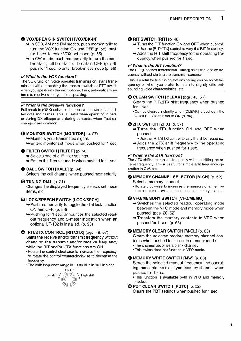
@3 VOX/BREAK-IN SWITCH [VOX/BK-IN] In SSB, AM and FM modes, push momentarily to
turn the VOX function ON and OFF (p. 55); pushfor 1 sec. to enter VOX set mode (p. 55).
In CW mode, push momentarily to turn the semibreak-in, full break-in or break-in OFF (p. 56);push for 1 sec. to enter break-in set mode (p. 56).
What is the VOX function?The VOX function (voice operated transmission) starts trans-mission without pushing the transmit switch or PTT switchwhen you speak into the microphone; then, automatically re-turns to receive when you stop speaking.
What is the break-in function?Full break-in (QSK) activates the receiver between transmit-ted dots and dashes. This is useful when operating in nets,or during DX pileups and during contests, when “fast ex-changes” are common.
@4 MONITOR SWITCH [MONITOR] (p. 57)Monitors your transmitted signal.Enters monitor set mode when pushed for 1 sec.
@5 FILTER SWITCH [FILTER] (p. 50)Selects one of 3 IF filter settings.Enters the filter set mode when pushed for 1 sec.
@6 CALL SWITCH [CALL] (p. 64)Selects the call channel when pushed momentarily.
@7 TUNING DIAL (p. 21)Changes the displayed frequency, selects set modeitems, etc.
@8 LOCK/SPEECH SWITCH [LOCK/SPCH]Push momentarily to toggle the dial lock function
ON and OFF. (p. 53)Pushing for 1 sec. announces the selected read-
out frequency and S-meter indication when anoptional UT-102 is installed. (p. 90)
@9 RIT/∂∂TX CONTROL [RIT/∂∂TX] (pgs. 48, 57)Shifts the receive and/or transmit frequency withoutchanging the transmit and/or receive frequencywhile the RIT and/or ∂TX functions are ON.•Rotate the control clockwise to increase the frequency,or rotate the control counterclockwise to decrease thefrequency.
•The shift frequency range is ±9.99 kHz in 10 Hz steps.
#0 RIT SWITCH [RIT] (p. 48)Turns the RIT function ON and OFF when pushed.
•Use the [RIT/∂TX] control to vary the RIT frequency.Adds the RIT shift frequency to the operating fre-
quency when pushed for 1 sec.
What is the RIT function?The RIT (Receiver Incremental Tuning) shifts the receive fre-quency without shifting the transmit frequency.
This is useful for fine tuning stations calling you on an off-fre-quency or when you prefer to listen to slightly different-sounding voice characteristics, etc.
#1 CLEAR SWITCH [CLEAR] (pgs. 48, 57)Clears the RIT/∂TX shift frequency when pushedfor 1 sec.•Can be cleared instantly when [CLEAR] is pushed if theQuick RIT Clear is set to ON (p. 86).
#2 ∂∂TX SWITCH [∂∂TX] (p. 57)Turns the ∂TX function ON and OFF when
pushed.•Use the [RIT/∂TX] control to vary the ∂TX frequency.
Adds the ∂TX shift frequency to the operatingfrequency when pushed for 1 sec.
What is the ∂∂TX function?The ∂TX shifts the transmit frequency without shifting the re-ceive frequency. This is useful for simple split frequency op-eration in CW, etc.
#3 MEMORY CHANNEL SELECTOR [M-CH] (p. 62)Select a memory channel.•Rotate clockwise to increase the memory channel; ro-tate counterclockwise to decrease the memory channel.
#4 VFO/MEMORY SWITCH [VFO/MEMO]Switches the selected readout operating mode
between the VFO mode and memory mode whenpushed. (pgs. 20, 62)
Transfers the memory contents to VFO whenpushed for 1 sec. (p. 65)
#5 MEMORY CLEAR SWITCH [M-CL] (p. 63)Clears the selected readout memory channel con-tents when pushed for 1 sec. in memory mode.•The channel becomes a blank channel.•This switch does not function in VFO mode.
#6 MEMORY WRITE SWITCH [MW] (p. 63)Stores the selected readout frequency and operat-ing mode into the displayed memory channel whenpushed for 1 sec.•This function is available both in VFO and memorymodes.
#7 PBT CLEAR SWITCH [PBTC] (p. 52)Clears the PBT settings when pushed for 1 sec.
Low shift High shift
RIT/∂TX
IC-746PRO.qxd 02.4.2 11:31 Page 4

Front panel (continued)
#8 TRANSMIT FREQUENCY CHECK SWITCH [XFC](pgs. 45, 48)Monitors the transmit frequency when pushed andheld.•While pushing this switch, the transmit frequency can bechanged with the tuning dial, keypad or memo pad.
•When the split lock function is turned ON, pushing [XFC]cancels the dial lock function. (p. 60)
#9 MEMO PAD-WRITE SWITCH [MP-W] (p. 68)Programs the selected readout frequency and op-erating mode into a memo pad.•The 5 most recent entries remain in memo pads.•The transmit frequency is programmed when pushed to-gether with [XFC].
•The memo pad capacity can be expanded from 5 to 10in set mode for your convenience. (p. 85)
$0 TRANSMIT INDICATOR [TX]Lights red while transmitting.
$1 MEMO PAD-READ SWITCH [MP-R] (p. 68)Each push calls up a frequency and operatingmode in a memo pad. The 5 (or 10) most recentlyprogrammed frequencies and operating modes canbe recalled, starting from the most recent.•The memo pad capacity can be expanded from 5 to 10in set mode for your convenience. (p. 85)
$2 RECEIVE INDICATOR [RX]Lights green while receiving a signal and when thesquelch is open.
$3 LOCK INDICATOR [LOCK] (p. 53)Lights when the dial lock function is activated.
$4 QUICK TUNING SWITCH [TS] (p. 21)Turns the quick tuning step ON and OFF.
•While the quick tuning indicator is displayed, the fre-quency can be changed in programmed kHz steps.
•0.1, 1, 5, 9, 10, 12.5, 20 and 25 kHz quick tuningsteps are available.
While the quick tuning step is OFF, turns the 1 Hzstep ON and OFF when pushed for 1 sec.•1 Hz indication appears, and the frequency can bechanged in 1 Hz steps.
While the quick tuning step is ON, enters thequick tuning step set mode when pushed for1 sec.
$5 VFO SELECT SWITCH [A/B] (p. 20)Push to toggle between VFO A and VFO B.Push for 1 sec. to equalize the frequency and op-
erating mode of the two VFO’s.
Quick tuning indicator
5
1 PANEL DESCRIPTION
2001 NEW 2001 NEW
NR A/NOTCH
NER ANT
HF/VHF TRANSCEIVER
NR NOTCH
AF
MIC GAIN RF PWR CW PITCH
F 1 F 2 F 3 F 4 F 5
XFC
MP-W
GENE 50 0
21 7 24 8 28 9
14 510 4 18 6
3.5 21.8 1 7 3
144 ENT
MP-R
TX RXLOCK
TWIN PBT
M-CH
RIT CLEAR∂TX
RIT/∂TX
TS
SPLIT
PBTC
F-INP
A/BV/M
MW
M-CL
KEY SPEED P.AMP/ATT NB VOX/BK-IN MONITOR CALL LOCK/SPCH
RF/SQL
i746PRO
MENU SSB CW/RTTY AM/FM FILTER
$7
$4
$5
$6
$3$2$1$0#9#8
%2 %0 $9 $8%1
IC-746PRO.qxd 02.4.2 11:31 Page 5

6
1PANEL DESCRIPTION
2001 NEW
$6 SPLIT SWITCH [SPLIT]Turns the split function ON and OFF when
pushed.(p. 59)Turns the quick split function ON, when pushed
for 1 sec. (p. 60)•The offset frequency is shifted from the displayed fre-quency.
•The quick split function can be turned OFF using setmode. (p. 83)
Turns the split function ON and sets the transmitfrequency after inputting an offset frequency withthe keypad (±4 MHz in 1 kHz steps; p. 59).
$7 PASSBAND TUNING CONTROLS [TWIN PBT]Adjust the receiver’s “passband width” of the DSPfilter. (p. 52)•Passband width and shift frequency are displayed in themulti-function switch indicator.
•Push [PBTC] for 1 sec. to clear the settings when not inuse.
•Variable range is set to half of the IF filter passbandwidth. 25 Hz steps and 50 Hz steps are available.
•These controls function as an IF shift control while in AMmode and when the RTTY filter is turned ON. Only theinner control may function in this case.
What is the PBT control?General PBT function electronically narrows the IF passbandwidth to reject interference. This transceiver uses the DSPcircuit for the PBT function.
$8 SPLIT INDICATOR (p. 59)Lights during split operation.
$9 FREQUENCY INPUT SWITCH [F-INP] (p. 22)Push to toggle keypad input between frequency andband.•The frequency input indicator lights when fre-quency input is selected for the keypad.
%0 FREQUENCY INPUT INDICATOR (p. 22)Lights when frequency input from the keypad is en-abled.
%1 KEYPADPushing a key selects the operating band.
• [GENE • ] selects the general coverage band.Pushing the same key 2 or 3 times calls up other
stacked frequencies and modes in the band.(p. 19)• Icom’s triple band stacking register memorizes 3 fre-quencies in each band.
After pushing [F-INP], enter a keyed frequency.Pushing [144 ENT] is necessary at the end.(p. 22)•e.g. to enter 14.195 MHz, push [F-INP] [1.8 1] [10 4][GENE • ] [1.8 1] [28 9] [14 5] [144 ENT].
%2 LCD FUNCTION DISPLAY(See pgs. 9, 10 for details.)Shows the operating frequency, function switchmenus, band scope screen, memory name screen,set mode settings, etc.
PBT1
PBT2
TWIN PBT
Low cut High cutCenter
TWIN PBT TWIN PBT TWIN PBT
– +
IC-746PRO.qxd 02.4.2 11:31 Page 6
Rear panel
!5 !3 t
r
!2 !1 !0 o i u y
q w e
!4
7
1 PANEL DESCRIPTION
2001 NEW 2001 NEW
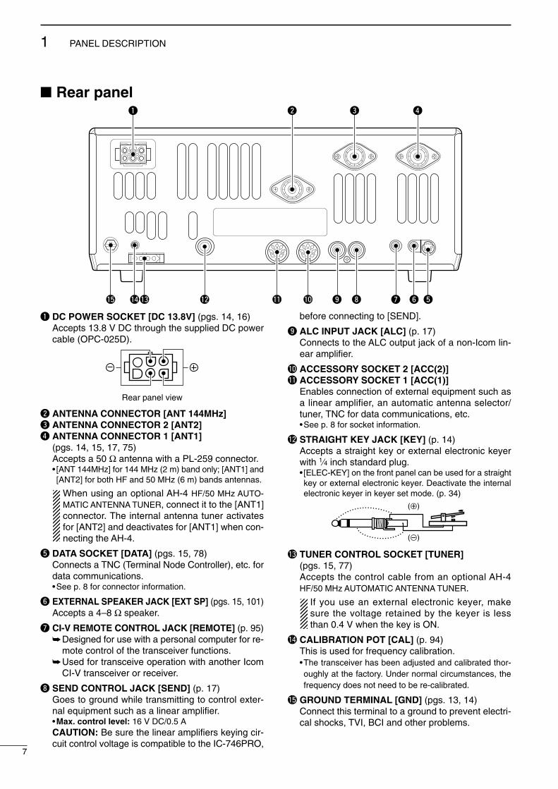
q DC POWER SOCKET [DC 13.8V] (pgs. 14, 16)Accepts 13.8 V DC through the supplied DC powercable (OPC-025D).
w ANTENNA CONNECTOR [ANT 144MHz]e ANTENNA CONNECTOR 2 [ANT2]r ANTENNA CONNECTOR 1 [ANT1]
(pgs. 14, 15, 17, 75)Accepts a 50 Ω antenna with a PL-259 connector.• [ANT 144MHz] for 144 MHz (2 m) band only; [ANT1] and[ANT2] for both HF and 50 MHz (6 m) bands antennas.
When using an optional AH-4 HF/50 MHz AUTO-MATIC ANTENNA TUNER, connect it to the [ANT1]connector. The internal antenna tuner activatesfor [ANT2] and deactivates for [ANT1] when con-necting the AH-4.
t DATA SOCKET [DATA] (pgs. 15, 78)Connects a TNC (Terminal Node Controller), etc. fordata communications.•See p. 8 for connector information.
y EXTERNAL SPEAKER JACK [EXT SP] (pgs. 15, 101)Accepts a 4–8 Ω speaker.
u CI-V REMOTE CONTROL JACK [REMOTE] (p. 95)Designed for use with a personal computer for re-
mote control of the transceiver functions.Used for transceive operation with another Icom
CI-V transceiver or receiver.
i SEND CONTROL JACK [SEND] (p. 17)Goes to ground while transmitting to control exter-nal equipment such as a linear amplifier.•Max. control level: 16 V DC/0.5 ACAUTION: Be sure the linear amplifiers keying cir-cuit control voltage is compatible to the IC-746PRO,
before connecting to [SEND].
o ALC INPUT JACK [ALC] (p. 17)Connects to the ALC output jack of a non-Icom lin-ear amplifier.
!0 ACCESSORY SOCKET 2 [ACC(2)]!1 ACCESSORY SOCKET 1 [ACC(1)]
Enables connection of external equipment such asa linear amplifier, an automatic antenna selector/tuner, TNC for data communications, etc.•See p. 8 for socket information.
!2 STRAIGHT KEY JACK [KEY] (p. 14)Accepts a straight key or external electronic keyerwith 1⁄4 inch standard plug.• [ELEC-KEY] on the front panel can be used for a straightkey or external electronic keyer. Deactivate the internalelectronic keyer in keyer set mode. (p. 34)
!3 TUNER CONTROL SOCKET [TUNER](pgs. 15, 77)Accepts the control cable from an optional AH-4HF/50 MHz AUTOMATIC ANTENNA TUNER.
If you use an external electronic keyer, makesure the voltage retained by the keyer is lessthan 0.4 V when the key is ON.
!4 CALIBRATION POT [CAL] (p. 94)This is used for frequency calibration.•The transceiver has been adjusted and calibrated thor-oughly at the factory. Under normal circumstances, thefrequency does not need to be re-calibrated.
!5 GROUND TERMINAL [GND] (pgs. 13, 14)Connect this terminal to a ground to prevent electri-cal shocks, TVI, BCI and other problems.
(+)
(_)
Rear panel view
IC-746PRO.qxd 02.4.2 11:31 Page 7

8
1PANEL DESCRIPTION
2001 NEW
DDATA SOCKET
DACC SOCKETSACC (1) PIN No. NAME DESCRIPTION SPECIFICATIONS
1
2
34 5
6 78
“High” level : More than 2.4 V1 RTTY Controls RTTY keying “Low” level : Less than 0.6 V
Output current : Less than 2 mA
2 GND Connects to ground. Connected in parallel with ACC(2) pin 2.
Input/output pin. (HF/50 MHz only) Ground level : –0.5 V to 0.8 V
3 HSEND Goes to ground when transmitting. Output current : Less than 20 mA
When grounded, transmits. Input current (Tx) : Less than 200 mAConnected in parallel with ACC(2) pin 3.
4 MOD Modulator input. Input impedance : 10 kΩConnects to a modulator. Input level : Approx. 100 mV rms
AF detector output. Output impedance : 4.7 kΩ5 AF Fixed, regardless of [AF] position in Output level : 100–300 mV rms
default settings. (see notes below)
6 SQLS Squelch output. SQL open : Less than 0.3 V/5 mAGoes to ground when squelch opens. SQL closed : More than 6.0 V/100 µA
7 13.8 V 13.8 V output when power is ON. Output current : Max. 1 AConnected in parallel with ACC(2) pin 7.
Control voltage : –4 V to 0 V8 ALC ALC voltage input. Input impedance : More than 10 kΩ
Connected in parallel with ACC(2) pin 5.
ACC (2) PIN No. NAME DESCRIPTION SPECIFICATIONS
1
2
34 5
6 7
1 8 V Regulated 8 V output. Output voltage : 8 V ±0.3 VOutput current : Less than 10 mA
2 GND Same as ACC(1) pin 2.
3 HSEND Same as ACC(1) pin 3.
4 BAND Band voltage output. Output voltage : 0 to 8.0 V(Varies with amateur band)
5 ALC Same as ACC (1) pin 8.
Input/output pin (144 MHz only) Ground level : –0.5 V to +0.8 V6 VSEND Goes to ground when transmitting. Output current : Less than 20 mA
When grounded, transmits. Input current (Tx) : Less than 200 mA
7 13.8 V Same as ACC(1) pin 7.
Rear panel view
Rear panel view
DATA PIN No. NAME DESCRIPTION
1 2
3 4
5 6
1 DATA IN Input terminal for data transmit. (1200 bps: AFSK/9600 bps: G3RUH, GMSK)
2 GND Common ground for DATA IN, DATA OUT and AF OUT.
3 PTT P PTT terminal for packet operation. Connect ground to transmit data.
4 DATA OUT Data out terminal for 9600 bps operation only.
5 AF OUT Data out terminal for 1200 bps operation only.
Squelch out terminal. Becomes high (+8 V) when the transceiver receives a signalwhich opens the squelch.
6 P SQL •To avoid unnecessary TNC transmission, connect squelch to the TNC to inhibit trans-mission when receiving signals.
•Keep audio output at a normal level, otherwise a “P SQL”signal will not be output.
Rear panel view
IC-746PRO.qxd 02.4.2 11:31 Page 8

9
1 PANEL DESCRIPTION
2001 NEW 2001 NEW
LCD display
q FREQUENCY READOUTSShows the operating frequency.
w MULTI-FUNCTION METER INDICATIONShows receiving signal strength, etc. during re-
ceive.Shows transmit output power, ALC and SWR dur-
ing transmit.
e VOX INDICATOR (p. 55)Appears when the VOX function is activated.
r MICROPHONE COMPRESSOR INDICATOR (p. 58)Appears when the microphone compressor is acti-vated.
t MULTI-FUNCTION SWITCH INDICATOR (p. 11)Indicates the functions assigned to the multi-func-tion switches ([F1]–[F5]).
y DSP FILTER INDICATOR (p. 50)Shows the selected IF filter.
u MEMORY CHANNEL READOUTS (p. 62)Shows the selected memory channel.
i SELECT MEMORY CHANNEL INDICATOR (p. 72)Appears when the selected memory channel is setas a select memory channel.
o BLANK MEMORY INDICATOR (p. 62)Appears when the selected memory channel isblank.
!0 1⁄4 TUNING DIAL SPEED INDICATOR (p. 21)Appears when the tuning dial speed is set so thatone rotation is equal to 1⁄4 of the normal rotation.
!1 VOICE SQUELCH CONTROL INDICATOR (p. 54)Appears during VSC (Voice Squelch Control) func-tion is activated.
!2 MODE INDICATORS (p. 23)Shows the selected operating mode.• “D” appears when SSB data, AM data or FM data modeis selected.
!3 ANTENNA INDICATOR (p. 75)Indicates which antenna connector is used forHF/50 MHz.
!4 ANTENNA TUNER INDICATORS (pgs. 76, 77) “TUNE” appears when the antenna tuner is ON;
“TUNE” appears and flashes during tuning. “EXT” appears when the optional AH-4 external
antenna tuner is connected to [ANT1].
q
w
t
!0
o
iu
y
!1!2!3!4
er
IC-746PRO.qxd 02.4.2 11:31 Page 9

10
1PANEL DESCRIPTION
2001 NEW
LCD display (continued)
!5 BREAK-IN INDICATORS (p. 56) “FBK-IN” appears when the full break-in function
is activated. “BK-IN” appears when the semi break-in function
is activated.
!6 MONITOR INDICATOR (p. 57)Appears when the monitor function is activated.
!7 PREAMP INDICATORS (p. 48)Appears when the preamp is activated.
!8 ATTENUATOR INDICATOR (p. 48)Appears when the attenuator is activated.
!9 AGC INDICATORS (p. 49)Shows the selected AGC time constant.• “F” for AGC fast; “M” for AGC middle; “S” for AGCslow; “-OFF” for AGC OFF.
@0 NOISE BLANKER INDICATOR (p. 51)Appears when the noise blanker is activated.
@1 DTCS INDICATOR (p. 43)Appears during DTCS operation.
@2 TONE SQUELCH INDICATORS “T” appears when the repeater tone is activated.
(p. 44) “TSQL” appears during tone squelch operation.
(p. 42)
@3 DUPLEX INDICATOR (p. 44)“DUP–” or “DUP+” appears during repeater opera-tion.
@4 NOISE REDUCTION INDICATOR (p. 53)Appears when the noise reduction is activated.
@5 NOTCH INDICATORS (p. 53) “NOTCH” appears when the manual notch func-
tion is activated. “ANOTCH” appears when the automatic notch
function is activated.
@6 SPLIT INDICATOR (pgs. 59, 60)Appears during split operation.
@7 MEMORY INDICATOR (p. 62)Appears during memory mode.
@8 VFO INDICATORS (p. 20)Indicates whether VFO A or VFO B is selected.
@9 RIT/∂∂TX INDICATORS (pgs. 48, 57)Appears during RIT or ∂TX operation and indicatesthe frequency offset.
!7!8
!9@0
@7@6@5@4
@2
@3
@1
@9
!5!6
@8
IC-746PRO.qxd 02.4.2 11:31 Page 10

11
1 PANEL DESCRIPTION
2001 NEW 2001 NEW
Multi function switchesDDM1 FUNCTIONSDuring SSB operation
During SSB data operation
During CW operation
During RTTY operation
During AM operation
During FM operation
AGC (p. 49)Push momentarily to change the time
constant of the AGC circuit. Push for 1 sec. to enter to the AGC set
mode.
DUPLEX (p. 44)Push momentarily to select the duplex di-
rection or turn the function OFF. • “DUP–” or “DUP+” indicator appears duringduplex operation.
Push for 1 sec. to turn the one-touch re-peater function ON/OFF.
SPEECH COMPRESSOR (p. 58)Push momentarily to turn the speech
compressor function ON/OFF.• “COMP” indicator appears when the speechcompressor is ON.
Push for 1 sec. to enter to the compres-sor set mode.
1⁄4 TUNING FUNCTION (p. 21)Push to turn the 1⁄4 tuning functionON/OFF. • “ ” indicator appears when the 1⁄4 tuningfunction is ON.
TRANSMISSION BANDWIDTH (p. 58)Push to select the transmission bandwidth.•Bandwidth is selectable from narrow, middleand wide.
MEMORY KEYER MENU (p. 29)Push to select the memory keyer or keyersend menu, depending on the KEYER1st Menu setting in the set mode (p. 86).
RTTY MENU (p. 36)Push to select the RTTY menu.
BAND SCOPE FUNCTION (p. 47)Push to select the band scope screen.
DDM2 FUNCTIONS
SCAN MENU (p. 70)Push to select the scan menu.
MEMORY NAME MENU (p. 67)Push to select the memory name screen.
SWR GRAPH FUNCTION (p. 61)Push to indicate the SWR graph screen.
TONE CONTROL SET MODE (p. 89)Push to enter the audio tone set mode.
VSC FUNCTION (p. 54)Push to turn the VSC (Voice Squelch Con-trol) function ON and OFF.F 5
VSC
F 4
TCN
F 3
SWR
F 2
MEM
F 1
SCN
F 1 F 2 F 3 F 4 F 5
SCN MEM SWR TCN VSC
F 5
SCP
F 4
RTY
F 4
KEY
F 4
TBW
F 3
1/4
F 3
CMP
F 2
DUP
F 1
AGC
F 1 F 2 F 3 F 4 F 5
AGC DUP CMP TON SCP
F 1 F 2 F 3 F 4 F 5
AGC DUP CMP SCP
F 1 F 2 F 3 F 4 F 5
AGC DUP 1/4 RTY SCP
F 1 F 2 F 3 F 4 F 5
AGC DUP 1/4 KEY SCP
F 1 F 2 F 3 F 4 F 5
AGC DUP 1/4 SCP
F 1 F 2 F 3 F 4 F 5
AGC DUP CMP TBW SCP
IC-746PRO.qxd 02.4.2 11:31 Page 11

Microphone (HM-36)
q UP/DOWN SWITCHES [UP]/[DN]Change the selected readout frequency or memorychannel.•Continuous pushing changes the frequency or memorychannel number continuously.
•While pushing [XFC], the transmit readout frequency canbe controlled while in spilt frequency operation.
•The [UP]/[DN] switch can simulate a key paddle. Presetin the keyer set mode. (p. 34)
•MICROPHONE CONNECTOR(Front panel view)
•HM-36 SCHEMATIC DIAGRAM
w PTT SWITCHPush and hold to transmit; release to receive.
CAUTION: DO NOT short pin 2 to ground as thiscan damage the internal 8 V regulator.NOTE: DC voltage is applied to pin 1 for micro-phone operation. Take care when using a non-Icommicrophone.
y GND (PTT ground)
t PTT
r Main readout squelch switch
q Microphone input
w +8 V DC output
e Frequency up/down
u GND (Microphone ground)
i Main readout AF output (varies with [AF]/[BAL])
q
w
[MIC]FUNCTION DESCRIPTIONPin No.
w +8 V DC output Max. 10 mA
eFrequency up Ground
Frequency down Ground through 470 Ω
rSquelch open “Low” level
Squelch closed “High” level
+
+
q
w
er
t
y
u
i
4700p
4700p10µ
0.33µ
MICROPHONE
MICELEMENT
2k
470
DOWN UP
PTT RECEIVE
TRANSMIT
MICROPHONE CABLE MICROPHONE PLUG
12
1PANEL DESCRIPTION
2001 NEWIC-746PRO.qxd 02.4.2 11:31 Page 12

2
13
INSTALLATION AND CONNECTIONS
2001 NEW
UnpackingAfter unpacking, immediately report any damage to thedelivering carrier or dealer. Keep the shipping cartons.
For a description and a diagram of accessory equip-ment included with the IC-746PRO, see ‘Supplied ac-cessories’ on p. ii of this manual.
Selecting a locationSelect a location for the transceiver that allows ade-quate air circulation, free from extreme heat, cold, orvibrations, and away from TV sets, TV antenna ele-ments, radios and other electromagnetic sources.
The base of the transceiver has an adjustable standfor desktop use. Set the stand to one of two angles de-pending on your operating conditions.
GroundingTo prevent electrical shock, television interference(TVI), broadcast interference (BCI) and other prob-lems, ground the transceiver through the GROUNDterminal on the rear panel.
For best results, connect a heavy gauge wire or strapto a long earth-sunk copper rod. Make the distance be-tween the [GND] terminal and ground as short as pos-sible.
RWARNING: NEVER connect the [GND]terminal to a gas or electric pipe, since the connec-tion could cause an explosion or electric shock.
Antenna connectionFor radio communications, the antenna is of critical im-portance, along with output power and sensitivity. Se-lect antenna(s), such as a well-matched 50 Ω antenna,and feedline. 1.5:1 or better of Voltage Standing WaveRatio (VSWR) is recommended for your desired band.Of course, the transmission line should be a coaxialcable.
When using 1 antenna, use the [ANT1] connector.
CAUTION: Protect your transceiver from lightningby using a lightning arrestor.
Antenna SWREach antenna is tuned for a specified frequencyrange and SWR may be increased out-of-range.When the SWR is higher than approx. 2.0:1, thetransceiver’s power drops to protect the final transis-tor. In this case, an antenna tuner is useful to matchthe transceiver and antenna. Low SWR allows fullpower for transmitting even when using the antennatuner. The IC-746PRO has an SWR meter to moni-tor the antenna SWR continuously.
PL-259 CONNECTOR INSTALLATION EXAMPLE
30 mm ≈ 9⁄8 in 10 mm ≈ 3⁄8 in 1–2 mm ≈ 1⁄16 in
30 mm
10 mm (soft solder)
10 mm
1–2 mm
solder solder
Softsolder
Coupling ring
Slide the coupling ring down. Strip the cable jacket and soft solder.
Slide the connector body on and solder it.
Screw the coupling ring onto the connector body.
Strip the cable as shown at left. Soft sol-der the center con-ductor.
q
w
e
r
IC-746PRO.qxd 02.4.2 11:31 Page 13

2
14
INSTALLATION AND CONNECTIONS
Required connections•Front panel
•Rear panel
i746PRO
POWER
F 1
MENU SSB
F 2
CW/RTTY
F 3
AM/FM
F 4
FILTER
F 5
XFC
MP-W
GENE 50
MP-R
0
21 7 24 8 28 9
10 4 14 5 18 6
1.8 1 3.5 2 7 3
144 ENT
TS
A/B
SPLIT
F-INP
V/M M-CL
PBTC MW
TWIN PBT
M-CH
LOCK/SPCH
∂TXRIT CLEAR
RIT/∂TX
CALLMONITORVOX/BK-INNBP.AMP/ATTKEY SPEEDCW PITCHRF PWRMIC GAIN
HF/VHF TRANSCEIVER
TRANSMIT
PHONES
ELEC-KEY
MIC
TUNER ANT
NR NOTCH
AF RF/SQL
NR A/NOTCH
CW KEY
MICROPHONES (p. 101)
A straight key can be used when the internal electronic keyer is turned OFF in keyer set mode. (p. 34)
HM-36 SM-20(optional)
(dot)(com)(dash)
GROUND (p. 13)
Use the heaviest gauge wire or strap available and make the connection as short as possible.
Grounding prevents electrical shocks, TVI and other problems.
ANTENNA 1, 2 (pgs. 13, 75)[Example]: ANT1 for 1.8–18 MHz bands
ANT2 for 21–50 MHz bands
DC POWER SUPPLY
STRAIGHT KEY
PS-125(Optional)
144 MHz ANTENNA (pgs. 13, 75)
Connect a VHF (60–144 MHz)antenna; impedance: 50 Ω.
(+)
(_)
IC-746PRO.qxd 02.4.2 11:31 Page 14

Advanced connections•Front panel
•Rear panel
15
2 INSTALLATION AND CONNECTIONS
2001 NEW 2001 NEW
POWER
TRANSMIT
PHONES
ELEC-KEY
MIC
NR A/NOTCH
TUNER ANT
HF/VHF TRANSCEIVER
NR NOTCH
AF
MIC GAIN RF PWR CW PITCH
F 1 F 2 F 3 F 4 F 5
XFC
MP-W
GENE 50 0
21 7 24 8 28 9
14 510 4 18 6
3.5 21.8 1 7 3
144 ENT
MP-R
TX RXLOCK
TWIN PBT
M-CH
RIT CLEAR∂TX
RIT/∂TX
TS
SPLIT
PBTC
F-INP
A/BV/M
MW
M-CL
KEY SPEED P.AMP/ATT NB VOX/BK-IN MONITOR CALL LOCK/SPCH
RF/SQL
i746PRO
MENU SSB CW/RTTY AM/FM FILTER
HEADPHONES
MICThe AFSK modulation signal can be input from [MIC]. (p. 78)
AH-2b
AH-4 (p. 77)ANTENNA 1, 2 (p. 17)Connects a linear amplifier, antenna selector, etc.
[SEND], [ALC] (p. 17)Used for connecting a non-Icom linear ampli-fier.
When using the AH-4, it must be connected to the [ANT1] connector.
[REMOTE] (p. 95)Used for computer control and transceive operation.
[DATA] (p. 78)
EXTERNAL SPEAKER (p. 101)
SP-21(optional)
ACC SOCKETS (pgs. 8, 78)
IC-746PRO.qxd 02.4.2 11:31 Page 15

16
2INSTALLATION AND CONNECTIONS
2001 NEW
Power supply connectionsUse an optional DC power supply with a 25 A capacityand above when operating the transceiver with ACpower. Refer to the diagrams below.
CONNECTING PS-125 DC POWER SUPPLY
CONNECTING A DC POWER SUPPLY
CONNECTING A VEHICLE BATTERY
30 A fusesAC cable
TransceiverAC outlet A DC power supply
13.8 V; at least 23 A
Black_
Red+
to DC powersocket
SuppliedDC power cable
12 Vbattery
SuppliedDC power cable
+ red_ black
Crimp
Solder
Grommet
NEVER connect toa 24 V battery.
NOTE: Use terminals forthe cable connections.
NEVER connect to a battery without supplied DCfuses, otherwise a fire hazard may occur.
PS-125
Connect to an AC outletusing the supplied AC cable.
DC power cable
DC powersocket
Transceiver
CAUTION: Before connecting the DC powercable, check the following important items. Makesure:•The [POWER] switch is OFF.•Output voltage of the power source is 12–15 Vwhen you use a non-Icom power supply.
•DC power cable polarity is correct.Red : positive + terminalBlack : negative _ terminal
IC-746PRO.qxd 02.4.2 11:31 Page 16

2001 NEW
17
2 INSTALLATION AND CONNECTIONS
2001 NEW
Linear amplifier connectionsCONNECTING THE IC-PW1
Turn OFF the transceiver’s antenna tuner while tuning the IC-PW1’s tuner.
CONNECTING A NON-ICOM LINEAR AMPLIFIERR WARNING:Set the transceiver output power and linear ampli-fier ALC output level referring to the linear amplifierinstruction manual. Be sure the linear amplifier key-ing circuit control voltage is compatible with the IC-746PRO, before connecting to [SEND] jack.
The ALC input level must be in the range 0 V to –4V, and the transceiver does not accept positive volt-age. Non-matched ALC and RF power settingscould cause a fire or ruin the linear amplifier.
The specifications for the SEND relay are 16 V/DC0.5 A. If this level is exceeded, a large externalrelay must be used.
External antenna tuner connectionsCONNECTING THE AH-4
The AH-4 must be connected to [ANT1].
To anantenna ACC(1)
ANT
ANT1ACC(2)
INPUT1
REMOTE
EXCITER1 1&2
GND
GND
IC-PW1AC outlet(Non-European versions: 100—120/220—240 V European version : 230 V)
Ground Transceiver
RE
MO
TE
Remote control cable (supplied with the IC-PW1)
ACC cable (supplied with the IC-PW1)
Be sure to connect the cableto the 7-pin ACC(2) jack.
Coaxial cable(supplied with the IC-PW1)
Coaxial cable (from AH-4)
ANT1Transceiver
GroundAH-4
Control cable
Long wire or optional AH-2b
50 Ω coaxial cable
Non-Icom linear amplifier SENDALC
To anantenna
RF OUTPUT RF INPUT
ALC
SEND
ANT1Transceiver
Use the [ANT1] connector when connecting a linearamplifier.
IC-746PRO.qxd 02.4.2 11:31 Page 17

Before first applying power, make sure all connectionsrequired for your system are complete by referring toChapter 2. Then, reset the transceiver using the fol-lowing procedure.
NOTE: When first applying power or when operat-ing in cold environments, the display may flicker orappear faint. This is normal and will disappear oncethe transceiver has warmed up.
q Make sure the transceiver power is OFF.w While pushing [M-CL] and [F-INP], push [POWER]
for 1 sec. to turn power ON.•The internal CPU is reset.•The transceiver displays its initial VFO frequency whenresetting is complete.
e Correct the set mode settings after resetting, if de-sired.
Resetting CLEARS all programmed contents inmemory channels and returns programmed valuesin set mode to default values.
3
18
BASIC OPERATION
When first applying power (CPU resetting)
Initial settingsAfter resetting the transceiver, set controls andswitches as shown in the figure below.
CW : ClockwiseCCW : Counterclockwise
POWER
TRANSMIT
PHONES
ELEC-KEY
MIC
NR A/NOTCH
TUNER ANT
HF/VHF TRANSCEIVER
NR NOTCH
AF
MIC GAIN RF PWR CW PITCH
F 1 F 2 F 3 F 4 F 5
XFC
MP-W
GENE 50 0
21 7 24 8 28 9
14 510 4 18 6
3.5 21.8 1 7 3
144 ENT
MP-R
TX RXLOCK
TWIN PBT
M-CH
RIT CLEAR∂TX
RIT/∂TX
TS
SPLIT
PBTC
F-INP
A/BV/M
MW
M-CL
KEY SPEED P.AMP/ATT NB VOX/BK-IN MONITOR CALL LOCK/SPCH
RF/SQL
i746PRO
MENU SSB CW/RTTY AM/FM FILTER
[NR]: Max. CCW [NOTCH]: Max. CCW
[AF]: Max. CCW
[TRANSMIT]: OFF
[MIC GAIN]: Max. CCW
[RF PWR]: Max. CCW [CW PITCH]: 12 o’clock
[RF/SQL]: 12 o’clock
[KEY SPEED]: Max. CCW
[POWER] [F-INP] [M-CL]
2001 NEWIC-746PRO.qxd 02.4.2 11:31 Page 18

19
3 BASIC OPERATION
2001 NEW 2001 NEW
Selecting an operating bandThe transceiver has a triple band stacking register.This means that the last 3 operating frequencies andmodes used on a particular band are automaticallymemorized.
See the table below for a list of the bands availableand the default settings for each register.
DUsing the band stacking registersqPush [14 5], then select a frequency and an operat-
ing mode.•Frequency and operating mode are memorized in thefirst band stacking register.
wPush [14 5] again, then select another frequencyand operating mode.•This frequency and operating mode are memorized inthe second band stacking register.
ePush [14 5] again, then select another frequencyand operating mode.•This frequency and operating mode are memorized inthe third band stacking register.
•When a fourth frequency and operating mode are se-lected on a band, the first register set in step q, is over-written.
Band keys
BAND REGISTER 1 REGISTER 2 REGISTER 3
1.8 MHz 1.900000 MHz CW 1.910000 MHz CW 1.915000 MHz CW
3.5 MHz 3.550000 MHz LSB 3.560000 MHz LSB 3.580000 MHz LSB
7 MHz 7.050000 MHz LSB 7.060000 MHz LSB 7.020000 MHz CW
10 MHz 10.120000 MHz CW 10.130000 MHz CW 10.140000 MHz CW
14 MHz 14.100000 MHz USB 14.200000 MHz USB 14.050000 MHz CW
18 MHz 18.100000 MHz USB 18.130000 MHz USB 18.150000 MHz USB
21 MHz 21.200000 MHz USB 21.300000 MHz USB 21.050000 MHz CW
24 MHz 24.950000 MHz USB 24.980000 MHz USB 24.900000 MHz CW
28 MHz 28.500000 MHz USB 29.500000 MHz USB 28.100000 MHz CW
50 MHz 50.100000 MHz USB 50.200000 MHz USB 51.000000 MHz FM
144 MHz 145.000000 MHz FM 145.100000 MHz FM 145.200000 MHz FM
General 15.000000 MHz USB 15.100000 MHz USB 15.200000 MHz USB
[Example]: 14 MHz band
GENE 50 0
21 7 24 8 28 9
14 510 4 18 6
3.5 21.8 1 7 3
144 ENT
IC-746PRO.qxd 02.4.2 11:31 Page 19

20
3BASIC OPERATION
2001 NEW
Selecting VFO/memory mode
VFO is an abbreviation of Variable Frequency Oscilla-tor, and is commonly referred to as a main tuning func-tion. The tuning dial is often called the “VFO knob.”
Push [V/M] to switch between VFO and memorymodes.•Pushing [V/M] for 1 sec. transfers the contents of the se-lected memory channel to VFO mode (p. 65).
VFO operationThe transceiver has 2 VFOs and are called VFO A andVFO B. You can use the desired VFO to call up a fre-quency and operating mode for your operation.
DDSelecting the VFO A/B Push [A/B] to switch between the VFO A and
VFO B.• “VFO A” or “VFO B” appears.
DDVFO equalization Push [A/B] for 1 sec. to equalize the undisplayed
VFO condition to the displayed VFO.•3 beeps sound when the VFO equalization is completed.
CONVENIENTUse two VFOs as a quick memoryWhen you find a new station, but you wish to continuesearching, the Two VFO system can be used for quick mem-ory storage.
qPush [A/B] for 1 sec. to store the displayed frequency intothe undisplayed VFO.
wContinue searching for stations.ePush [A/B] to retrieve the stored frequency.rTo continue searching for a station, push [A/B] again.
[A/B]
Either one appears
Push for 1 sec.A/B
[V/M]
IC-746PRO.qxd 02.4.2 11:31 Page 20

21
3 BASIC OPERATION
2001 NEW 2001 NEW
Frequency setting The transceiver has several tuning methods for conve-nient frequency tuning.
DDTuning with the tuning dialq Push the desired band key on the keypad 1–3
times.•3 different frequencies can be selected on each bandwith the band key. (p. 19)
w Rotate the tuning dial to set the desired frequency.
If the dial lock function is activated, the lock indicatorlights, and the tuning dial does not function. In thiscase, push [LOCK/SPCH] to deactivate the lockfunction. (see p. 53 for details)
DDQuick tuning step The operating frequency can be changed in kHz steps(0.1, 1, 5, 9, 10, 12.5, 20 or 25 kHz selectable) forquick tuning.
q Push [SSB], [CW/RTTY] or [AM/FM] to select thedesired operation mode.
w Push [TS] momentarily to activate the quick tuningfunction.• “” appears.
e Push [TS] for 1 sec. to enter the tuning step setmode.
r Rotate the tuning dial to select the desired tuningstep.
t Push [TS] to exit the tuning step set mode.
DD 1⁄4 Tuning step function (SSB data, CW and RTTY only)While operating in SSB data/CW/RTTY, the 1⁄4 functionis available for critical tuning. Dial rotation is reduced to1⁄4 of normal when the 1⁄4 function is in use.
While M1 is selected with [MENU], push [F3 1/4]to toggle the 1⁄4 function ON and OFF.
DAuto tuning step functionWhen rotating the tuning dial rapidly, the tuning stepautomatically changes several times as selected.
q Push [MENU] for 1 sec. to enter the set mode.w Push [F1≤] or [F2 ≥] to select the DIAL Auto
TS item.e Rotate the tuning dial to select the function ON
(HIGH or LOW) and OFF.•HIGH : Approx. 5 times faster •LOW : Approx. 2 times faster •OFF : Auto tuning step is turned OFF.
r Push [MENU] to exit the set mode.
Band keys
Tuning dial
[TS]Select mode
1kHzSSB
1⁄4 indicator
27 HIGHDIAL Auto TS
IC-746PRO.qxd 02.4.2 11:31 Page 21

22
3BASIC OPERATION
2001 NEW
DDSelecting the 1 Hz stepThe minimum tuning step of 1 Hz can be used for finetuning.
q Push [TS] momentarily to turn the quick tuning stepOFF • “” disappears.
w Push [TS] for 1 sec. to toggle the 1 Hz tuning stepON and OFF.
DDBand edge warning beepWhen selecting a frequency that lies outside of aband’s specified frequency range, a warning beepsounds.
This function can be turned OFF in set mode, if de-sired. (p. 82)
DDFrequency setting with the keypadThe transceiver has a keypad for direct frequencyentry as described below.
q Push [F-INP].•F-INP indicator lights
w Input the desired frequency.• Input “ • ” (decimal point) between the MHz units and kHzunits.
e Push [144 ENT] to enter the input frequency.•To cancel the input, push [A/B] instead of [144 ENT].
Lights when keypad input is activated.Keypad [F-INP]
21.280 MHz 21.245 MHz
14.025 MHz
Push
[EXAMPLE]
50 0
21 7
14 5
10 4
10 4
18 6
3.5 21.8 1F-INP GENE
50 050 0
3.5 2
GENE
14 5
144 ENT
706 kHz
Push 144 ENT
144 ENT
F-INP
GENEPush F-INP
[TS]
1 Hz indicator
IC-746PRO.qxd 02.4.2 11:31 Page 22

23
3 BASIC OPERATION
2001 NEW 2001 NEW
Operating mode selectionSSB (USB/LSB), SSB data (USB data/LSB data), CW,CW reverse (CW-R), RTTY, RTTY-R (RTTY reverse),AM, AM data, FM and FM data modes are available inthe IC-746PRO. Select the desired operation mode asfollows.
To select a mode of operation, push the desired modeswitch momentarily. Push the switch again to togglebetween USB and LSB, CW/CW-R and RTTY/RTTY-R, AM and FM, if necessary. Push the switch for 1 sec.to toggle between CW and CW-R, RTTY and RTTY-R,or to select data mode, if necessary.See the diagram below right for the order of selection.
Microphone signals are muted when data mode isselected.
•Selecting SSB mode Push [SSB] to select USB or LSB.
•USB is selected first when above 10 MHz; or LSB is se-lected first when below 10 MHz operation.
•After USB or LSB is selected, push [SSB] to toggle be-tween USB and LSB.
•After USB or LSB is selected, push [SSB] for 1 sec. toselect USB data or LSB data mode, respectively.
•Selecting CW/RTTY mode Push [CW/RTTY] to select CW or RTTY.
•After CW/CW-R or RTTY/RTTY-R is selected, push[CW/RTTY] to toggle between CW and RTTY.
•After CW or RTTY is selected, push [CW/RTTY] for1 sec. to toggle between CW and CW reverse, or, RTTYand RTTY reverse mode, respectively.
•Selecting AM/FM mode Push [AM/FM] to select AM or FM.
•After AM or FM is selected, push [AM/FM] to toggle be-tween AM and FM mode.
•After AM or FM is selected, push [AM/FM] for 1 sec. toselect AM data or FM data mode, respectively.
Volume setting Rotate [AF] control to output a suitable audio level.
AF RF/SQL
No audio output Max. audio output
Decreases Increases
[SSB] [CW/RTTY] [AM/FM]
SSB
CW/RTTY
AM/FM
D USB USB
CW-R CW
D AM AM
Push mode switch for 1 sec.
Push mode switchmomentarily.
LSB D LSB
RTTY RTTY-R
FM D FM
[AF] control
IC-746PRO.qxd 02.4.2 11:31 Page 23

3BASIC OPERATION
24
2001 NEW
Adjusts the RF gain and squelch threshold level. Thesquelch removes noise output from the speaker(closed position) when no signal is received. •The squelch is particularly effective for FM. It is also avail-able for other modes.
•The control can be set as the RF gain control only (squelchis fixed open) or squelch control (RF gain is fixed at maxi-mum) in set mode (p. 82). See below right.
•The 11 to 12 o’clock position is recommended for any set-ting of the [RF/SQL] control.
Adjusting RF gain (Receive sensitivity)Normally, [RF/SQL] is set to the 11 o’clock position.Rotate [RF/SQL] to the 11 o’clock position for maxi-mum sensitivity. •Rotating counterclockwise from the maximum position re-duces sensitivity.
•The S-meter indicates receive sensitivity.
Adjusting squelch (Removing non-signal noise)Rotate [RF/SQL] clockwise when receiving no signal,until the noise just disappears.• [RX] indicator light goes out.•Rotating [RF/SQL] past the threshold point invokes the S-meter squelch— this allows you to set a minimum signallevel needed to open the squelch.
•When setting as RF gain/squelch control
•When functioning as RF gain control (Squelch isfixed open; SSB, CW, RTTY only)
•When functioning as squelch control (RF gain isfixed at maximum)
Squelch is open.
S-meter squelch
S-meter squelchthreshold
Noise squelch threshold (FM mode)
Shallow Deep
Noise squelch (FM mode)
Minimum RF gain
Adjustablerange
Maximum RF gain
Recommended level
RF gain adjustablerange
Maximum RF gain
S-meter squelch
Noise squelch (FM mode)
Squelch is open.
Squelch and receive (RF) sensitivity[RF/SQL] control
SET MODE OPERATION
RF+SQLCan be used in all modes.
(default)Functions as noise squelch or S-metersquelch in AM and FM; S-metersquelch only in other modes.
SQL Operates as a squelch control.•RF gain is fixed at max. sensitivity.
Operates as an RF gain control inSSB, CW and RTTY.
AUTO •Squelch is fixed open.Operates as a squelch control in AM
and FM.•RF gain is fixed at max. sensitivity.
IC-746PRO.qxd 02.4.2 11:31 Page 24

25
3 BASIC OPERATION
2001 NEW 2001 NEW
Basic transmit operation
DDTransmittingBefore transmitting, monitor your selected operatingfrequency to make sure transmitting won’t cause inter-ference to other stations on the same frequency.
q Push [TRANSMIT] or [PTT] (microphone) to trans-mit.•The [TX] indicator lights red.
w Push [TRANSMIT] again or release [PTT] (micro-phone) to return to receive.
DDMicrophone gain adjustmentBefore transmitting, monitor your selected operatingfrequency to make sure transmitting won’t cause inter-ference to other stations on the same frequency.
q Push [PTT] (microphone) to transmit.•Talk into the microphone at your normal voice level.
w While talking into the microphone, rotate [MICGAIN] so that the ALC meter reading doesn’t gooutside the ALC zone (see right).
e Release [PTT] (microphone) to return to receive.
[TRANSMIT]
[RF PWR][MIC GAIN]
[TX] indicator
ALC zone
Before transmitting, monitor your selected oper-ating frequency to make sure transmitting won’tcause interference to other stations on the samefrequency. It’s good Amateur practice to listenfirst, and then, even if nothing is heard, ask “isthe frequency in use” once or twice, before youbegin operating on that frequency.
IC-746PRO.qxd 02.4.2 11:31 Page 25
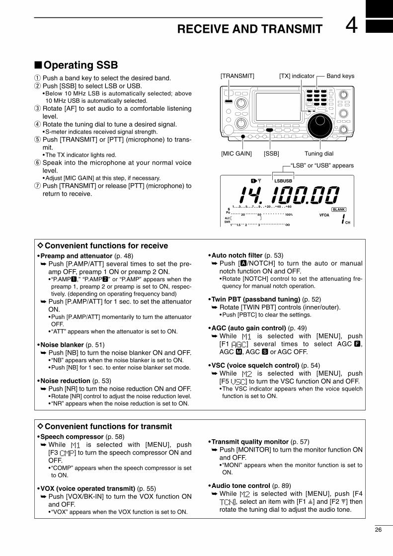
2001 NEW
4
26
RECEIVE AND TRANSMIT
Operating SSB q Push a band key to select the desired band.w Push [SSB] to select LSB or USB.
•Below 10 MHz LSB is automatically selected; above10 MHz USB is automatically selected.
e Rotate [AF] to set audio to a comfortable listeninglevel.
r Rotate the tuning dial to tune a desired signal.•S-meter indicates received signal strength.
t Push [TRANSMIT] or [PTT] (microphone) to trans-mit.•The TX indicator lights red.
y Speak into the microphone at your normal voicelevel.•Adjust [MIC GAIN] at this step, if necessary.
u Push [TRANSMIT] or release [PTT] (microphone) toreturn to receive.
Band keys[TX] indicator[TRANSMIT]
[MIC GAIN] [SSB] Tuning dial
“LSB” or “USB” appears
DDConvenient functions for receive•Preamp and attenuator (p. 48) Push [P.AMP/ATT] several times to set the pre-
amp OFF, preamp 1 ON or preamp 2 ON.• “P.AMP1,” “P.AMP2” or “P.AMP” appears when thepreamp 1, preamp 2 or preamp is set to ON, respec-tively. (depending on operating frequency band)
Push [P.AMP/ATT] for 1 sec. to set the attenuatorON.•Push [P.AMP/ATT] momentarily to turn the attenuatorOFF.
• “ATT” appears when the attenuator is set to ON.
•Noise blanker (p. 51) Push [NB] to turn the noise blanker ON and OFF.
• “NB” appears when the noise blanker is set to ON.•Push [NB] for 1 sec. to enter noise blanker set mode.
•Noise reduction (p. 53) Push [NR] to turn the noise reduction ON and OFF.
•Rotate [NR] control to adjust the noise reduction level.• “NR” appears when the noise reduction is set to ON.
•Auto notch filter (p. 53) Push [A/NOTCH] to turn the auto or manual
notch function ON and OFF.•Rotate [NOTCH] control to set the attenuating fre-quency for manual notch operation.
•Twin PBT (passband tuning) (p. 52) Rotate [TWIN PBT] controls (inner/outer).
•Push [PBTC] to clear the settings.
•AGC (auto gain control) (p. 49) While M1 is selected with [MENU], push
[F1 AGC] several times to select AGC F,AGC M, AGC S or AGC OFF.
•VSC (voice squelch control) (p. 54) While M2 is selected with [MENU], push
[F5 VSC] to turn the VSC function ON and OFF.•The VSC indicator appears when the voice squelchfunction is set to ON.
DDConvenient functions for transmit•Speech compressor (p. 58) While M1 is selected with [MENU], push
[F3 CMP] to turn the speech compressor ON andOFF.• “COMP” appears when the speech compressor is setto ON.
•VOX (voice operated transmit) (p. 55) Push [VOX/BK-IN] to turn the VOX function ON
and OFF.• “VOX” appears when the VOX function is set to ON.
•Transmit quality monitor (p. 57) Push [MONITOR] to turn the monitor function ON
and OFF.• “MONI” appears when the monitor function is set toON.
•Audio tone control (p. 89) While M2 is selected with [MENU], push [F4
TCN], select an item with [F1 ≤] and [F2 ≥] thenrotate the tuning dial to adjust the audio tone.
IC-746PRO.qxd 02.4.2 11:31 Page 26

27
4 RECEIVE AND TRANSMIT
2001 NEW 2001 NEW
Operating CWq Push a band key to select the desired band.w Push [CW/RTTY] to select CW.
•After CW mode is selected, push [CW/RTTY] for 1 sec.to toggle between CW and CW-R modes.
e Rotate [AF] to set audio to a comfortable listeninglevel.
r Rotate the tuning dial to simultaneously tune a de-sired signal and its side tone.•S-meter indicates received signal strength.
t Push [TRANSMIT] to transmit.•The TX indicator lights red.
y Use the electric keyer or paddle to key your CW sig-nals.•The Po meter indicates transmitted CW signal strength.
u Adjust CW speed with [KEY SPEED]. i Push [TRANSMIT] to return to receive.
Band keys[TX] indicator[TRANSMIT]
[CW PITCH]
[KEY SPEED]
[CW/RTTY] Tuning dial
“CW” or “CW-R” appears
DDConvenient functions for receive•Preamp and attenuator (p. 48) Push [P.AMP/ATT] several times to set the pre-
amp OFF, preamp 1 ON or preamp 2 ON.• “P.AMP1,” “P.AMP2” or “P.AMP” appears when thepreamp 1, preamp 2 or preamp is set to ON, respec-tively. (depending on operating frequency band)
Push [P.AMP/ATT] for 1 sec. to set the attenuatorON.•Push [P.AMP/ATT] momentarily to turn the attenuatorOFF.
• “ATT” appears when the attenuator is set to ON.
•Noise blanker (p. 51) Push [NB] to turn the noise blanker ON and OFF.
• “NB” appears when the noise blanker is set to ON.•Push [NB] for 1 sec. to enter noise blanker set mode.
•Noise reduction (p. 53) Push [NR] to turn the noise reduction ON andOFF.
•Rotate [NR] control to adjust the noise reduction level.• “NR” appears when the noise reduction is set to ON.
•Auto notch filter (p. 53) Push [A/NOTCH] to turn the auto or manual
notch function ON and OFF.•Rotate [NOTCH] control to set the attenuating fre-quency for manual notch operation.
•Twin PBT (passband tuning) (p. 52) Rotate [TWIN PBT] controls (inner/outer).
•Push [PBTC] to clear the settings.
•AGC (auto gain control) (p. 49) While M1 is selected with [MENU], push
[F1 AGC] several times to select AGC F,AGC M, AGC S or AGC OFF.
• 1⁄4 function (p. 21) While M1 is selected with [MENU], push
[F3 1/4] to turn the 1⁄4 function ON and OFF.
DDConvenient functions for transmit•Break-in function (p. 56) Push [VOX/BK-IN] several times to set the break-
in OFF, semi break-in or full break-in.• “BK-IN” or “F BK-IN” appears when the semi break-inor full break-in is set to ON, respectively.
IC-746PRO.qxd 02.4.2 11:31 Page 27

28
4RECEIVE AND TRANSMIT
2001 NEW
DDAbout CW reverse modeCW reverse mode receives CW signals with a reverseside CW carrier point like that of LSB and USB modes.
Use when interfering signals are near a desired signaland you want to change the interference tone.
q Push [CW/RTTY] several times to select CW mode.w Push [CW/RTTY] for 1 sec. to select CW or CW-R
mode.•Check the interfering tone.
DDAbout CW pitch controlThe received CW audio pitch and monitored CW audiocan be adjusted to suit your preference (300 to 900 Hzin 25 Hz steps) without changing the operating fre-quency.
DDAbout keying speedThe transceiver’s internal electronic keyer speed canbe adjusted from 6 to 60 wpm. Rotate [KEY SPEED] clockwise to increase keying
speed; counterclockwise to decrease keying speed.
DDCW side tone functionWhen the transceiver is in the receive condition (andthe break-in function is OFF— p. 56) you can listen tothe tone of your CW signal without actually transmit-ting. This allows you to match your transmit signal ex-actly to another station’s. This also convenient for CWpractice. CW side tone level can be adjusted in keyerset mode (p. 33).
Push for 1 sec.
BFO
CW-R mode (USB side)
BFO
Desired signal
CW mode (LSB side)
Interference Desired signalInterference
CW/RTTY
[CW PITCH]
[KEY SPEED]
IC-746PRO.qxd 02.4.2 11:31 Page 28

29
4 RECEIVE AND TRANSMIT
2001 NEW 2001 NEW
Electronic keyer functionsThe transceiver has a number of convenient functionsfor the electronic keyer that can be accessed from thememory keyer menu.
q Push [CW/RTTY] to select CW mode.w Push [MENU] to select M1.e Push [F4 KEY] to select the memory keyer menu.
•The selectable menu can be changed with the keyersend menu in the set mode. (p. 87)
r Push one of the multi-function keys ([F1] to [F5]) toselect an item in the memory keyer menu. See thediagram below.•Push [MENU] to return to the previous indication.
DD IN CW MODE
F 1 F 2 F 3 F 4 F 5
F 1 F 2 F 3 F 4 F 5
F 1 F 2 F 3 F 4 F 5
F 1 F 2 F 3 F 4 F 5
F 1 F 2 F 3 F 4 F 5
F 1 F 2 F 3 F 4 F 5
AGC DUP 1/4 KEY SCP
M1 M2 M3 M4 -1
5O%1Side Tone Level
Normal1Number Style
CQ TEST CQ TESTM1 ç å DEL SPC
Push [F4]
Push [MENU]Push [F4]
Push [F2]
Push [F3]
Push [F5]
• Keyer send menu (p. 30)
SND EDT 001 SET
• Memory keyer menu
• Keyer set mode (p. 33)
• Contest number set mode (p. 32)
• Edit menu (p. 31)
[MENU] [CW/RTTY]
IC-746PRO.qxd 02.4.2 11:31 Page 29

30
4RECEIVE AND TRANSMIT
2001 NEW
F 1 F 2 F 3 F 4 F 5
F 2F 1
F 4F 3
Repeat indicators Count up triggerindicator
Counter
M1 M2 M3 M4 -1
M1 M2 M3 M4 -1
M2 send indication
M1 M2 M3 M4 -1CQ TEST CQ 001
CQ TEST CQ 001
QRZ?
M1 M2 M3 M4 -1
UR 5NN001 B 001
001
M1 M2 M3 M4 -1UR 5NN001 B 001
CFM TU 001
M1 send indication
M2 send indicationRepeat send indication
M1 M2 M3 M4 -1
M4 send indication
M1 M2 M3 M4 -1
M3 send indication
DDMemory keyer send menuPre-set characters can be sent using the keyer sendmenu. Contents of the memory keyer are set using theedit menu.
•Transmittingq While M1 is selected in CW mode, push [F4 KEY]
to select the memory keyer menu.w Push [F2 SND] to select the keyer send menu.e Push [TRANSMIT] to set the transceiver to trans-
mit, or set the break-in function ON (p. 56).r Push one of the function keys ([F1] to [F4]) to send
the contents of the memory keyer.•Pushing a function key for 1 sec. repeatedly sends thecontents; push any function key to cancel the transmis-sion.
•The contest number counter, above [F5], is incrementedeach time the contents are sent.
•Push [F5] to reduce the contact number count by 1 whenresending contents to unanswered calls.
For your informationWhen an external keypad is connected to thepin 3 and pin 7 of the [MIC] connector, the pro-grammed contents, M1—M4, can be transmittedwithout selecting the keyer send menu.See p. 87 for details.
t Push [MENU] 2 times to return to M1.
IC-746PRO.qxd 02.4.2 11:31 Page 30

31
4 RECEIVE AND TRANSMIT
2001 NEW 2001 NEW
DDEditing a memory keyer The contents of the memory keyer memories can beset using the memory keyer edit menu. The memorykeyer can memorize and re-transmit 4 CW key codesfor often-used CW sentences, contact numbers, etc.Total capacity of the memory keyer is 50 charactersper memory channel.
•Programming contentsq Push [MENU] to select M1, then push [F4 KEY] to
select the memory keyer menu. w Push [F3 EDIT] to select edit menu.
•Memory keyer contents of the Channel 1 (M1) is indi-cated.
•Push [F5] to manually increment the contest number.e Push [F1] to select the desired memory keyer chan-
nel to be edited.r Input the desired character by rotating the tuning
dial or by pushing the keypad for number input.•Selectable characters (with the tuning dial);
NOTE: “^” is used to transmit a following word with nospace such as AR. Put “^” before a text stringsuch as ^AR, and the string “AR ” is sent with nospace.“*” is used to insert the CW contact number. Thecontact number automatically increments by 1.This function is only available for one memorykeyer channel at a time. Memory keyer channelM2 used “*” by default.
t Push [F2 ç] or [F3 å] to move the cursor back-wards or forwards, respectively.
y Repeat steps r and t to input the desired charac-ters.
u Push [MENU] 2 times to return to M1.
Pre-programmed contents
A B C D E F G H I J K L M N O P Q R S TU V W X Y Z / ? . , * ^
CH ContentsM1 CQ TEST CQ TEST DE JA1 JA1 TEST
M2 UR 5NN* BK
M3 CFM TU
M4 QRZ?
F 1 F 2 F 3 F 4 F 5
CQ TEST CQ TESTM1 ç å DEL SPC
UR 5NN* BKM2 ç å DEL SPC
• Edit menu
¥ M2 default indication
CFM TUM3 ç å DEL SPC
¥ M3 default indication
QSL TU DE JA3YM3 ç å DEL SPC
DE JA3YUA TESTM3 ç å DEL SPC
Example display— when inputting QSL TU DE JA3YUA TEST into M3.
QRZ?M4 ç å DEL SPC
¥ M4 default indication
Select M1 to M4Move cursor left/right
Clear characterInput space
When inputting an asterisk,the counter is incremented by 1.
IC-746PRO.qxd 02.4.2 11:31 Page 31

32
4RECEIVE AND TRANSMIT
2001 NEW
DDContest number set modeThis menu is used to set the contest (serial) numberand count up trigger, etc.
•Setting contentsq Push [MENU] to select M1, then push [F4 KEY] to
select the memory keyer menu. w Push [F4 001] to enter the contest number set
mode.e Push [F1≤] or [F2 ≥] to select the desired set item.r Set the desired condition using the tuning dial.
•Push [F3] for 1 sec. to select a default condition or value.t Push [MENU] 2 times to return to M1.
F 1 F 2 F 3 F 4 F 5
1
Set item up/down
5O%Side Tone Level
2. Count Up TrigThis selects which of the four memory slots will havethe contest serial number exchange. The count uptrigger allows the serial number to e automatically in-cremented after each complete serial number ex-change is sent.•M1, M2, M3 and M4 can be set. (default: M2)
M22Count Up Trig
1. Number StyleThis item sets the numbering system used for contact(serial) numbers— normal or morse cut numbers.
•Normal : Does not use morse cut number(default)
•190 ANO : Sets 1 as A, 9 as N and 0 as O.•190 ANT : Sets 1 as A, 9 as N and 0 as T.• 90 NO : Sets 9 as N and 0 as O.• 90 NT : Sets 9 as N and 0 as T.
Normal1Number Style
3. Present NumberThis item shows the current number for the count uptrigger channel set above.•Rotate the tuning dial to change the number, or push[F3 CLR] for 1 sec. to reset the current number to 001.
CLR 0013Present Number
IC-746PRO.qxd 02.4.2 11:31 Page 32
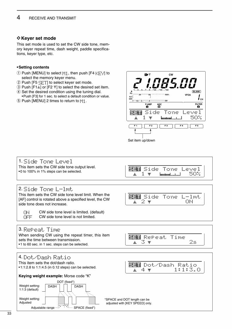
33
4 RECEIVE AND TRANSMIT
2001 NEW 2001 NEW
DDKeyer set modeThis set mode is used to set the CW side tone, mem-ory keyer repeat time, dash weight, paddle specifica-tions, keyer type, etc.
•Setting contentsq Push [MENU] to select M1, then push [F4 KEY] to
select the memory keyer menu. w Push [F5 SET] to select keyer set mode.e Push [F1≤] or [F2 ≥] to select the desired set item.r Set the desired condition using the tuning dial.
•Push [F3] for 1 sec. to select a default condition or value.t Push [MENU] 2 times to return to M1.
F 1 F 2 F 3 F 4 F 5
1
Set item up/down
5O%Side Tone Level
1. Side Tone LevelThis item sets the CW side tone output level.•0 to 100% in 1% steps can be selected. 5O%1
Side Tone Level
2. Side Tone L-lmtThis item sets the CW side tone level limit. When the[AF] control is rotated above a specified level, the CWside tone does not increase.
ON CW side tone level is limited. (default)OFF CW side tone level is not limited.
ON2Side Tone L-lmt
3. Repeat TimeWhen sending CW using the repeat timer, this itemsets the time between transmission.•1 to 60 sec. in 1 sec. steps can be selected.
2s3Repeat Time
4. Dot/Dash RatioThis item sets the dot/dash ratio.•1:1:2.8 to 1:1:4.5 (in 0.12 steps) can be selected.
Keying weight example: Morse code “K”
1:1:3.O4Dot/Dash Ratio
DASHWeight setting:1:1:3 (default)
Weight setting:Adjusted
DASH
DOT (fixed*)
Adjustable range SPACE (fixed*)
*SPACE and DOT length can be adjusted with [KEY SPEED] only.
IC-746PRO.qxd 02.4.2 11:31 Page 33

34
4RECEIVE AND TRANSMIT
2001 NEW
5. Rise TimeThis item sets the envelop time period which the out-put power becomes the set transmit power.•2, 4, 6 or 8 msec. can be selected.
4ms5Rise Time
Key action
Tx output power
• About rise timeTx
Rx
Set Tx power level
Time
6. Paddle PolarityThis item sets the paddle polarity.•Normal and reverse polarity can be selected. NORMAL6
Paddle Polarity
7. Keyer TypeThis item selects the keyer type for [ELEC-KEY] con-nector on the front panel.•ELEC-KEY, BUG KEY and Straight key can be selected.
ELEC-KEY7Keyer Type
8. MIC U/D KeyerThis item allows you to set the microphone [UP]/[DN]keys to be used as a paddle.
ON [UP]/[DN] switches can be used for CW.OFF [UP]/[DN] switches cannot be used for
CW.
NOTE: When “ON” is selected, the frequency andmemory channel cannot be changed usingthe [UP]/[DN] switches.
OFF8MIC U/D Keyer
IC-746PRO.qxd 02.4.2 11:31 Page 34

35
4 RECEIVE AND TRANSMIT
2001 NEW 2001 NEW
Operating RTTY (FSK)Before operating RTTY, be sure to consult the manualthat comes with your TNC.
q Push a band key to select the desired band.w Push [CW/RTTY] several times to select RTTY.
• After RTTY mode is selected, push [CW/RTTY] for1 sec. to toggle RTTY and RTTY-R modes.
e Rotate [AF] to set audio to a comfortable listeninglevel.
r Rotate the tuning dial to tune a desired signal.•S-meter indicates received signal strength.• If the received signal cannot be demodulated, try select-ing RTTY-R mode.
t Push [TRANSMIT] to set the transceiver to thetransmit condition or transmit a SEND signal fromyour TNC.•The TX indicator lights red.•The Po meter indicates transmitted RTTY signal strength.
y Operate the connected PC or TNC (TU) to transmitRTTY (FSK) signals.•Adjust [MIC GAIN] at this step, if necessary.
u Push [TRANSMIT] to return to receive.
Band keys[TX] indicator[TRANSMIT]
[CW/RTTY] Tuning dial
“RTTY” or “RTTY-R” appears
DDConvenient functions for receive•Preamp and attenuator (p. 48) Push [P.AMP/ATT] several times to set the pre-
amp OFF, preamp 1 ON or preamp 2 ON.• “P.AMP1,” “P.AMP2” or “P.AMP” appears when thepreamp 1, preamp 2 or preamp is set to ON, respec-tively. (depending on operating frequency band)
Push [P.AMP/ATT] for 1 sec. to set the attenuatorON.•Push [P.AMP/ATT] momentarily to turn the attenuatorOFF.
• “ATT” appears when the attenuator is set to ON.
•Noise blanker (p. 51) Push [NB] to turn the noise blanker ON and OFF.
• “NB” appears when the noise blanker is set to ON.•Push [NB] for 1 sec. to enter noise blanker set mode.
•Noise reduction (p. 53) Push [NR] to turn the noise reduction ON andOFF.
•Rotate [NR] control to adjust the noise reduction level.• “NR” appears when the noise reduction is set to ON.
•Twin PBT (passband tuning) (p. 52) Rotate [TWIN PBT] controls (inner/outer).
•Push [PBT C] to clear the settings.
•AGC (auto gain control) (p. 49) While M1 is selected with [MENU], push
[F1 AGC] several times to select AGC F,AGC M, AGC S or AGC OFF.
• 1⁄4 function (p. 21) While M1 is selected with [MENU], push
[F3 1/4] to turn the 1⁄4 function ON and OFF.
DDConvenient functions for transmit•Transmit quality monitor (p. 57) Push [MONITOR] to turn the monitor function ON
and OFF.• “MONI” appears when the monitor function is set toON.
IC-746PRO.qxd 02.4.2 11:31 Page 35

36
4RECEIVE AND TRANSMIT
2001 NEW
RTTY functionsThe transceiver has a number of convenient functionsfor the RTTY operation that can be accessed from theRTTY menu.
q Push [CW/RTTY] to select RTTY mode.w Push [MENU] to select M1.e Push [F4 RTY] to select the RTTY menu.r Push one of the multi-function keys ([F2], [F4] or
[F5]) to select an item in the RTTY menu. See thediagram below.•Push [MENU] to return to the previous indication.
DD IN RTTY MODE
F 1 F 2 F 3 F 4 F 5
F 1 F 2 F 3 F 4 F 5
F 1 F 2 F 3 F 4 F 5
F 1 F 2 F 3 F 4 F 5
F 1 F 2 F 3 F 4 F 5
F 1 F 2 F 3 F 4 F 5
AGC DUP 1/4 RTY SCP
DEC FIL SET
21251RTTY Mark
35O1Band Width
ADJ
RTTY-FIL ON
DEC FIL SET
• RTTY menu
• RTTY decoder screen (p. 38)
• RTTY filter set mode (p. 37)
• RTTY set mode (p. 39)
Push [F4]
Push [F4] for 1 sec.
Switches RTTY filter ON and OFF.
Push [F4]
Push [F5]
Push [F2]
[MENU] [CW/RTTY]
DDAbout RTTY reverse modeReceived characters are occasionally garbled whenthe receive signal is reversed between MARK andSpace. This reversal can be caused by incorrect TNCconnections, setting, commands, etc. To receive re-versed RTTY signals correctly, select RTTY-R mode.
While RTTY mode is selected, push [CW/RTTY]for 1 sec. to select the RTTY reverse mode.• “RTTY-R” appears when the RTTY reverse mode is se-lected.
•Push [CW/RTTY] for 1 sec. again to select the normalRTTY mode.
Normal Reverse
170 Hz170 Hz 2125 Hz2125 Hz
BFOBFO SpaceSpace MarkMark
IC-746PRO.qxd 02.4.2 11:31 Page 36

DDRTTY filter/Twin peak filterThe transceiver has 5 RTTY filters in addition to nor-mal IF filters. The passband width can be selectedfrom 1 kHz, 500 Hz, 350 Hz, 300 Hz and 250 Hz.When the RTTY filter is turned ON, the RTTY tuningmeter can be used.Moreover, the twin peak filter changes the receive fre-quency response by boosting 2 particular frequencies(2125 and 2295 Hz) for better copying of desiredRTTY signals.
•RTTY filter and twin peak filter settingq Push [CW/RTTY] to select RTTY mode.
•After RTTY mode is selected, push [CW/RTTY] for 1 sec.to select RTTY-R mode.
w Push [MENU] several times to select M1.e Push [F4 RTY] to select RTTY menu.r Push [F4 FIL] to turn the RTTY filter ON and OFF.
•When the RTTY filter is turned ON, the normal IF filternumber indication (1, 2 or 3) disappears.
t Push [F4 FIL] for 1 sec. to enter RTTY filter setmode (see below).
y Push [F1≤] to select bandwidth item.u Rotate the tuning dial to select the RTTY filter width
from 1 kHz, 500 Hz, 350 Hz, 300 Hz and 250 Hz.•Push [F3] for 1 sec. to select a default value.
i Push [F2 ≥] to select twin peak filter item.•The received audio volume may become greater whenthe twin peak filter is turned ON.
o Rotate the tuning dial to turn the twin peak filterfunction ON and OFF.
!0 Push [MENU] 2 times to return to M1.
•RTTY filter set mode
37
4 RECEIVE AND TRANSMIT
2001 NEW 2001 NEW
F1 F2 F3 F4 F5
F1 F2 F3 F4 F5
AGC DUP 1/4 RTY SCP
DEC FIL SETRTTY-FIL ON
Push [F4]
Disappears when the RTTY filter is turned OFF.
RTTY filter indicator
Rotate the tuning dial to the point where both sides of thedots appear equally.
1. Band WidthThis item sets the RTTY filter width.•250, 300, 350, 500 Hz and 1 kHz can be selected.
35O1Band Width
2. Twin Peak FILThis item turns the twin peak filter ON and OFF.
ON2Twin Peak FIL
IC-746PRO.qxd 02.4.2 11:31 Page 37

38
4RECEIVE AND TRANSMIT
2001 NEW
F 1 F 2 F 3 F 4 F 5
F 1 F 2 F 3 F 4 F 5
F 1 F 2 F 3 F 4 F 5
AGC DUP 1/4 RTY SCP
DEC FIL SET
ADJ
RTTY-FIL ON
Push [F4]
Push [F2]
Appears while the RTTY decoder screen is freezedwith [F2] operation.Push [F3] to erase the displayed characters.
DDRTTY decoderThe transceiver has an RTTY decoder for Baudot(mark freq.: 2125 Hz, shift freq.: 170 Hz, 45 bps).
An external terminal unit (TU) or terminal node con-nector (TNC) is not necessary for receiving a Baudotsignal.
q Push [CW/RTTY] to select RTTY mode.•After RTTY mode is selected, push [CW/RTTY] for 1 sec.to select RTTY-R mode.
w Push [MENU] several times to select M1.e Push [F4 RTY] to select RTTY menu.r Push [F4 FIL] to turn the RTTY filter ON.
•The RTTY decoder does not function when the RTTY fil-ter is turned OFF.
t Push [F2 DEC] to turn the RTTY decoder ON.•RTTY decoder screen appears.
y Push [F2] to freeze the current screen.• “H” appears while the function is in use.
u Push [F3] for 1 sec. to clear the displayed charac-ters.
i Push [MENU] to exit the RTTY decoder screen.
•Setting the decoder threshold levelAdjust the RTTY decoder threshold level if some char-acters are displayed when no signal is received.
q Call up the RTTY decoder screen as describedabove.
w Push [F1 ADJ] to select the threshold level settingcondition.
e Rotate the tuning dial to adjust the RTTY decoderthreshold level.•Push [F3] for 1 sec. to select the default condition.
r Push [MENU] to exit the RTTY decoder screen.
The number of line of text can be selected from 2 or3 in the display. The UnShift On Space (USOS)function and new line code can be set in the RTTYset mode. (p. 39)
F 1 F 2 F 3 F 4 F 5
F 1 F 2 F 3 F 4 F 5
ADJ
å 9
Push [F1]
Threshold level indication
IC-746PRO.qxd 02.4.2 11:31 Page 38

39
4 RECEIVE AND TRANSMIT
2001 NEW 2001 NEW
DDRTTY set modeThis set mode is used to set the mark and shift fre-quencies, keying type, decode USOS function, etc.
•Setting contentsq Push [MENU] to select M1, then push [F4 RTY] to
select the RTTY menu. w Push [F5 SET] to select RTTY set mode.e Push [F1≤] or [F2 ≥] to select the desired set item.r Set the desired condition using the tuning dial.
•Push [F3] for 1 sec. to select a default condition or value.t Push [MENU] 2 times to return to M1. F 1 F 2 F 3 F 4 F 5
21251RTTY Mark
Set item up/down
1. RTTY MarkSets the mark frequency for RTTY operation.•1275, 1615 and 2125 Hz are selectable.
21251RTTY Mark
2. RTTY ShiftSets the shift frequency for RTTY operation.•170, 200 and 425 Hz are selectable.
17O2RTTY Shift
3. RTTY KeyingSelects the keying polarity from normal and reverse.
NORMAL Key open/close = Mark/SpaceREVERSE Key open/close = Space/Mark
NORMAL3RTTY Keying
4. Decode USOSTurn the USOS (UnShift On Space) function ON/OFF
ON Decode as letter code OFF Decode as character code
ON4Decode USOS
5. Decode New LineSelects the new line code of the internal RTTY decoder.CR: Carriage Return; LF: Line Feed
CR,LF,CR+LF CR, LF and CR+LFCR+LF CR+LF only
CR,LF,CR+LF5Decode New Line
6. Decode ScreenSelects the number of the decoder indication from 2or 3 lines. 3line6
Decode Screen
IC-746PRO.qxd 02.4.2 11:31 Page 39

40
4RECEIVE AND TRANSMIT
2001 NEW
Operating AMq Push a band key to select the desired band.w Push [AM/FM] to select AM.e Rotate [AF] to set audio to a comfortable listening
level.r Rotate the tuning dial to tune a desired signal.
•S-meter indicates received signal strength.•The default tuning step for AM mode is 1 kHz; this canbe changed using the tuning step program mode. (p. 21)
t Push [TRANSMIT] or [PTT] (microphone) to trans-mit.•The TX indicator lights red.
y Speak into the microphone at your normal voicelevel.•Adjust [MIC GAIN] at this step, if necessary.
u Push [TRANSMIT] or release [PTT] (microphone) toreturn to receive.
Band keys[TX] indicator[TRANSMIT]
[MIC GAIN] [AM/FM] Tuning dial
Appears
DDConvenient functions for receive•Preamp and attenuator (p. 48) Push [P.AMP/ATT] several times to set the pre-
amp OFF, preamp 1 ON or preamp 2 ON.• “P.AMP1,” “P.AMP2” or “P.AMP” appears when thepreamp 1, preamp 2 or preamp is set to ON, respec-tively. (depending on operating frequency band)
Push [P.AMP/ATT] for 1 sec. to set the attenuatorON.•Push [P.AMP/ATT] momentarily to turn the attenuatorOFF.
• “ATT” appears when the attenuator is set to ON.
•Noise blanker (p. 51) Push [NB] to turn the noise blanker ON and OFF.
• “NB” appears when the noise blanker is set to ON.•Push [NB] for 1 sec. to enter noise blanker set mode.
•Noise reduction (p. 53) Push [NR] to turn the noise reduction ON and OFF.
•Rotate [NR] control to adjust the noise reduction level.• “NR” appears when the noise reduction is set to ON.
•Auto notch filter (p. 53) Push [A/NOTCH] to turn the auto or manual
notch filter ON and OFF.•Rotate [NOTCH] control to set the attenuating fre-quency for manual notch operation.
• IF shift (p. 52) Rotate [TWIN PBT] controls (inner only).
•Push [PBTC] to clear the settings.
•AGC (auto gain control) (p. 49) While M1 is selected with [MENU], push [F1
AGC] several times to select AGC F, AGC M,AGC S or AGC OFF.
•VSC (voice squelch control) (p. 54) While M2 is selected with [MENU], push
[F5 VSC] to turn the VSC function ON and OFF.•The VSC indicator appears when the voice squelchfunction is set to ON.
DDConvenient functions for transmit•Speech compressor (p. 58) While M1 is selected with [MENU], push [F3
CMP] to turn the speech compressor ON andOFF.• “COMP” appears when the speech compressor is setto ON.
•VOX (voice operated transmit) (p. 55) Push [VOX/BK-IN] to turn the VOX function ON
and OFF.• “VOX” appears when the VOX function is set to ON.
•Transmit quality monitor (p. 57) Push [MONITOR] to turn the monitor function ON
and OFF.• “MONI” appears when the monitor function is set toON.
•Audio tone control (p. 89) While M2 is selected with [MENU], push [F4
TCN], select an item with [F1 ≤] and [F2 ≥] thenrotate the tuning dial to adjust the audio tone.
IC-746PRO.qxd 02.4.2 11:31 Page 40

41
4 RECEIVE AND TRANSMIT
2001 NEW 2001 NEW
Operating FMq Push a band key to select the desired band.w Push [AM/FM] to select FM.e Rotate [AF] to set audio to a comfortable listening
level.r Rotate the tuning dial to tune a desired signal.
•S-meter indicates received signal strength.t Push [TRANSMIT] or [PTT] (microphone) to trans-
mit.•The TX indicator lights red.
y Speak into the microphone at your normal voicelevel.•Adjust [MIC GAIN] at this step, if necessary.
u Push [TRANSMIT] or release [PTT] (microphone) toreturn to receive.
Band keys[TX] indicator[TRANSMIT]
[MIC GAIN] [AM/FM] Tuning dial
Appears
DDConvenient functions for receive•Preamp and attenuator (p. 48) Push [P.AMP/ATT] several times to set the pre-
amp OFF, preamp 1 ON or preamp 2 ON.• “P.AMP1,” “P.AMP2” or “P.AMP” appears when thepreamp 1, preamp 2 or preamp is set to ON, respec-tively. (depending on operating frequency band)
Push [P.AMP/ATT] for 1 sec. to set the attenuatorON.•Push [P.AMP/ATT] momentarily to turn the attenuatorOFF.
• “ATT” appears when the attenuator is set to ON.
•Noise blanker (p. 51) Push [NB] to turn the noise blanker ON and OFF.
• “NB” appears when the noise blanker is set to ON.•Push [NB] for 1 sec. to enter noise blanker set mode.
•Noise reduction (p. 53) Push [NR] to turn the noise reduction ON and OFF.
•Rotate [NR] control to adjust the noise reduction level.• “NR” appears when the noise reduction is set to ON.
•Auto notch filter (p. 53) Push [A/NOTCH] to turn the auto or manual
notch filter ON and OFF.•Rotate [NOTCH] control to set the attenuating fre-quency for manual notch operation.
•VSC (voice squelch control) (p. 54) While M2 is selected with [MENU], push
[F5 VSC] to turn the VSC function ON and OFF.•The VSC indicator appears when the voice squelchfunction is set to ON.
DDConvenient functions for transmit•Speech compressor (p. 58) While M1 is selected with [MENU], push [F3
CMP] to turn the speech compressor ON andOFF.• “COMP” appears when the speech compressor is setto ON.
•VOX (voice operated transmit) (p. 55) Push [VOX/BK-IN] to turn the VOX function ON
and OFF.• “VOX” appears when the VOX function is set to ON.
•Transmit quality monitor (p. 57) Push [MONITOR] to turn the monitor function ON
and OFF.• “MONI” appears when the monitor function is set toON.
•Audio tone control (p. 89) While M2 is selected with [MENU], push [F4
TCN], select an item with [F1 ≤] and [F2 ≥] thenrotate the tuning dial to adjust the audio tone.
IC-746PRO.qxd 02.4.2 11:31 Page 41

42
4RECEIVE AND TRANSMIT
2001 NEW
DDTone squelch operationTone squelch operation is a method of communica-tions using selective calling. Only received signals hav-ing a matching tone will open the squelch. Beforecommunicating using tone squelch, all members ofyour party must agree on the tone squelch frequencyto use.
q Push [AM/FM] to select FM mode.w Push [MENU] several times to select M1.e Push [F4 TON] several times to turn the tone
squelch function ON.• “TSQL” appears
r Push [F4 TONE] for 1 sec. to enter tone frequencyset mode.
t Push [F1 TON] several times until TSQL Toneappears, if necessary.
y Rotate the tuning dial to select the desired tonesquelch frequency.•Push [F3] for 1 sec. to select the default frequency.
u Push [MENU] to return to M1.i Communicate in the usual manner.
•Available tone squelch frequencies (Unit: Hz)
F 1 F 2 F 3 F 4 F 5
F 1 F 2 F 3 F 4 F 5
AGC DUP CMP TON SCP
TON SCN 88.5HzTSQL Tone
Push [F4] for 1 sec.
67.069.371.974.477.079.782.5
085.4088.5091.5094.8097.4100.0103.5
107.2110.9114.8118.8123.0127.3131.8
136.5141.3146.2151.4156.7159.8162.2
165.5167.9171.3173.8177.3179.9183.5
186.2189.9192.8196.6199.5203.5206.5
210.7218.1225.7229.1233.6241.8250.3
254.1
IC-746PRO.qxd 02.4.2 11:31 Page 42

43
4 RECEIVE AND TRANSMIT
2001 NEW 2001 NEW
DDDTCS operationDTCS function is an another method of communica-tions using selective calling. Only received signals hav-ing a matching 3-digit code will open the squelch.
q Push [AM/FM] to select FM mode.w Push [MENU] several times to select M1.e Push [F4 TON] several times to turn the DTCS
function ON.• “DTCS” appears
r Push [F4 TON] for 1 sec. to enter tone frequencyset mode.
t Push [F1 TON] several times until DTCS Codeappears, if necessary.
y Rotate the tuning dial to select the desired DTCScode number and push [F5] to select the desiredcode polarity.NN : Normal polarity is used for both transmit and
receive.NR : Normal polarity is used for transmit, reversed
polarity is used for receive.RN : Reversed polarity is used for transmit, normal
polarity is used for receive.RR : Reversed polarity is used for both transmit
and receive.•Push [F3] for 1 sec. to select the default code and polar-ity.
u Push [MENU] to return to M1.i Communicate in the usual manner.
•Available tone codes
F 1 F 2 F 3 F 4 F 5
F 1 F 2 F 3 F 4 F 5
AGC DUP CMP TON SCP
TON SCN O23-NNDTCS Code
Push [F4] for 1 sec.
Push [F5] to select the polarity
Select a code with the tuning dial.
023025026031032036043047051053054065071
072073074114115116122125131132134143145
152155156162165172174205212223225226243
244245246251252255261263265266271274306
311315325331332343346351356364365371411
412413423431432445446452454455462464465
466503506516523526532546565606612624627
631632654662664703712723731732734743754
IC-746PRO.qxd 02.4.2 11:31 Page 43

44
4RECEIVE AND TRANSMIT
2001 NEW
Repeater operationA repeater amplifies received signals and retransmitsthem at a different frequency. When using a repeater,the transmit frequency is shifted from the receive fre-quency by an offset frequency. A repeater can be ac-cessed using split frequency operation with the shiftfrequency set to the repeater’s offset frequency.
q Push a band key to select the desired band.w Push [A/B] to select VFO A.e Push [AM/FM] to select FM.
•Pushing [AM/FM] toggles between AM and FM.r Rotate the tuning dial to set the repeater transmit
frequency.t While M1 is selected, push [F2 DUP] several times
to set the offset direction.• “DUP–” or “DUP+” appears•0.100 MHz for HF, 0.500 MHz for 50 MHz and0.600 MHz for 144 MHz band is set by default in setmode. (p. 83)
y Push [F4 TON] to turn the repeater tone ON.• “T” appears.•Set the tone frequency in tone frequency set mode inadvance, if desired. (p. 45) 88.5 Hz is set by default.
To transmit a 1750 Hz European repeater tone,push [F4 TON] while transmitting.
u Communicate in the normal way.
DDOne-touch repeater functionThis function allows you to set repeater operation withpush of one switch.
To set the transceiver for repeater operation usingthe one-touch repeater function, follow the steps qto r as above, then push [F2 DUP] for 1 sec.
Set the offset shift direction and frequency in ad-vance (p. 83) as well as the tone frequency (seep. 45).
F 1 F 2 F 3 F 4 F 5
F 1 F 2 F 3 F 4 F 5
AGC DUP CMP TON SCP
AGC DUP CMP TON SCP145.O8OOO
Push [F2], [F4]
Appears
F 1 F 2 F 3 F 4 F 5
F 1 F 2 F 3 F 4 F 5
AGC DUP CMP TON SCP
AGC DUP CMP TON SCP145.O8OOO
Push [F2] for 1 sec.
Appears
IC-746PRO.qxd 02.4.2 11:31 Page 44

45
4 RECEIVE AND TRANSMIT
2001 NEW 2001 NEW
DDTransmit frequency monitor checkYou may be able to receive the other party’s transmitsignal directly without having to go through a repeater.This function allows you to check this.
While receiving, push and hold [XFC] to see if youcan receive the other party’s transmit signal directly.•While holding [XFC], the offset direction and frequencyare displayed on the multi-function switch indicator.
DDRepeater tone frequenciesThe transceiver’s repeater tone frequency is set to88.5 Hz by default. This can be changed if desired.
q While M1 is selected, push [F4 TON] to turn thetone encoder ON.• “T” appears.
w Push [F4 TON] for 1 sec. to select the tone fre-quency set mode.
e Push [F1 TON] several times to select RptrTone, if necessary.
r Rotate the tuning dial to select the desired fre-quency. (see the table at right)
t Push [MENU] to return to M1.
DDStoring a non standard repeater q Turn the auto repeater function OFF in the set
mode. (p. 84)w Push [AM/FM] to select FM mode.e Push [V/M], then [A/B] to select VFO A.r Rotate the tuning dial to set the repeater output fre-
quency.•Set the tuning step if desired.
t Push [A/B] to select VFO B.y Rotate the tuning dial to set the repeater input fre-
quency.u Push [A/B] to select VFO A.i Push [SPLIT] to turn the split function ON.o Push [F4 TON] to turn the previously set tone en-
coder ON.!0 Rotate [M-CH] to select the desired memory chan-
nel.• “BLANK” appears when a blank channel is selected.
!1 Push [MW] for 1 sec. to store the contents in the se-lected memory channel.
AGC DUP CMP TON SCP-6OO.Ok
[XFC]
[AM/FM] [SPLIT] [A/B] [M-CH]
[MW][V/M]
67.069.371.974.477.079.782.5
085.4088.5091.5094.8097.4100.0103.5
107.2110.9114.8118.8123.0127.3131.8
136.5141.3146.2151.4156.7159.8162.2
165.5167.9171.3173.8177.3179.9183.5
186.2189.9192.8196.6199.5203.5206.5
210.7218.1225.7229.1233.6241.8250.3
254.1
TON SCN 88.5HzRptr Tone
•Available tone frequencies (Unit: Hz)
IC-746PRO.qxd 02.4.2 11:31 Page 45

46
4RECEIVE AND TRANSMIT
2001 NEW
DDAuto repeater function This function automatically activates the repeater set-tings (DUP– or DUP+ and/or tone encoder ON/OFF)when the operating frequency falls within the generalrepeater output frequency range and deactivates themwhen outside of the range.
Set the auto repeater function ON-1 or ON-2 in setmode in advance (p. 84). When set ON-1 or ON-2, re-peater settings are automatically activated accordingto the table below.
ON-1 automatically sets the duplex setting and ON-2automatically sets the duplex setting and tone encoderautomatically.
•Frequency range and offset direction
FREQUENCY RANGE DUPLEX DIRECTION
145.200–145.495 MHz minus duplex
146.610–146.995 MHz minus duplex
147.000–147.395 MHz plus duplex
18 ON-2Auto Repeater
18 ON-1Auto Repeater
18 OFFAuto Repeater
IC-746PRO.qxd 02.4.2 11:31 Page 46

5
47
FUNCTIONS FOR RECEIVE
2001 NEW
Simple band scope The band scope function allows you to visually checksignal conditions around a specified frequency. The IC-746PRO’s band scope function can be used in any op-erating mode and frequency band.
The band scope measures receive signal conditionsover a specified range on either side of a selected fre-quency in either VFO or memory modes.
q Rotate the tuning dial to tune a frequency.w While M1 is selected, push [F5 SCP] to select the
band scope menu.•Starts sweeping automatically with the previously se-lected sweeping step.
•During sweep, received signals cannot be heard.e Push [F5 STEP] several times to select the desired
sweep step.r Push [F1] to start sweeping, then stop automatically
after sweeping.•Push [F1] for 1 sec. to start continuous sweeping. In thiscase, it is necessary to push [F1] to stop sweeping.
•During sweep operation “ ” appears and receivedsignals cannot be heard.
• If there is a lot of signal noise, turn the preamp OFF andthe attenuator ON to reduce the signal input level andimprove the readability of the band scope.
t When rotating the tuning dial and you finding a sig-nal you wish to communicate on, then just commu-nicate in the normal way.• If you want to return to the previous frequency (beforerotating the tuning dial), push [F3] for 1 sec.
• If the selected frequency is set outside of the sweepedrange, flashes.
y While receiving, if you want to update the band con-ditions, repeat steps e and r as above.
“ ” or “ ”
0.5kSTEP
Sweep indicatorBand scope indicatorFrequency indicator markSweep step indicator
INDICATOR
Sweep
Band scope in-dicator
Frequency indicator mark
Sweep step
DESCRIPTION
While the band scope is “sweeping,” “ ” appears; while stopped “ ” appears. Receivedaudio is not emitted from the speaker while the band scope is “sweeping.”
Indicates the relative strength of signals and their location in relation to the center (displayed)frequency. Signal strength is relative to the S-meter level, S1 to S9, with each vertical dot in theband scope indicator equal to one segment of the S-meter. Signal activity is measured ±30steps from the center frequency with each step equal to the selected sweep step.
After a sweep, indicates the relative position of the selected frequency. When the selected fre-quency is outside of the sweep range, indicator flashes. After changing the fre-quency, push [F3] for 1 sec. to automatically return to the center frequency.
Indicates the selected sweep step. 0.5, 1, 2, 5, 10, 20 and 25 kHz are selectable. Each dot ofthe band scope indication is approx. equal to the selected sweep step.
“ ” or “ ”
F 1 F 2 F 3 F 4 F 5
F 1 F 2 F 3 F 4 F 5
Sweep step selectionSweep start/stop
O.5kSTEP
O.5kSTEP
Sweep indicator
IC-746PRO.qxd 02.4.2 11:31 Page 47

48
5FUNCTIONS FOR RECEIVE
Preamp/AttenuatorThe preamp amplifies received signals in the front endcircuit to improve the S/N ratio and sensitivity. Set thisto preamp 1 or preamp 2 when receiving weak signals.The attenuator prevents a desired signal from distor-tion when very strong signals are near the desired fre-quency or when very strong electric fields, such asfrom broadcasting stations, are near your location.These can both set independently for each band.
Push [P.AMP/ATT] several times to set the preampOFF, preamp 1 ON or preamp 2 ON.•When the preamp is ON, either “P.AMP 1” or“P.AMP 2” appears in the function display.
•When operating on the 144 MHz band, the preamp canonly be set to ON or OFF only— there is no preamp 1and preamp 2.
Push [P.AMP/ATT] for 1 sec. to set the attenuator ON.• “ATT” appears in the display when the function is set ON.•Push [P.AMP/ATT] momentarily to set the attenuator OFF.
RIT functionThe RIT (Receive Increment Tuning) function compen-sates for off-frequencies of the communicating station.The function shifts the receive frequency up to±9.99 kHz in 10 Hz steps without moving the transmitfrequency.•See #0 on p. 4 for function description.
q Push [RIT] to turn the RIT function ON and OFF.• “RIT” and the shifting frequency appear when the func-tion is ON.
w Rotate the [RIT/∂TX] control.•Push [CLEAR] for 1 sec. to reset the RIT frequency.•Push [CLEAR] momentarily to reset the RIT frequencywhen the quick RIT clear function is ON. (p. 86)
•Push [RIT] for 1 sec. to add the shift frequency to the op-erating frequency.
DDRIT monitor functionWhen the RIT function is ON, pushing and holding[XFC] allows you to monitor the operating frequencydirectly (RIT is temporarily cancelled).
[P.AMP/ATT]
PushP.AMP/ATT
PushP.AMP/ATT
PushP.AMP/ATT
Push for 1sec.P.AMP/ATT
PushP.AMP/ATT
Regular preamp, the most effective for 1.8 to21 MHz bands without IMD corruption.
High-gain preamp, the most effective for 24to 50 MHz bands.
Preamp activates for the VHF band (144 to146 MHz range; 108 to 174 for the USA version).
[RIT]
[CLEAR]
[RIT/∂TX] control
Appears
Regarding the use of the “P.AMP 2”The “P.AMP 2” is a high gain receive amplifier. When the“P.AMP 2” is used during times of strong electric fields, dis-tortion sometimes results. In such cases, use the trans-ceiver with the “P.AMP 1” or “P.AMP OFF” setting.
The “P.AMP 2” is most effective when:•Used on bands above 24 MHz and when electric fields areweak.
•Receive sensitivity is insufficient during low gain, or whileusing a narrow band antenna (such as small loop, a Bever-age antenna or a short Yagi antenna, etc.) is used.
IC-746PRO.qxd 02.4.2 11:31 Page 48
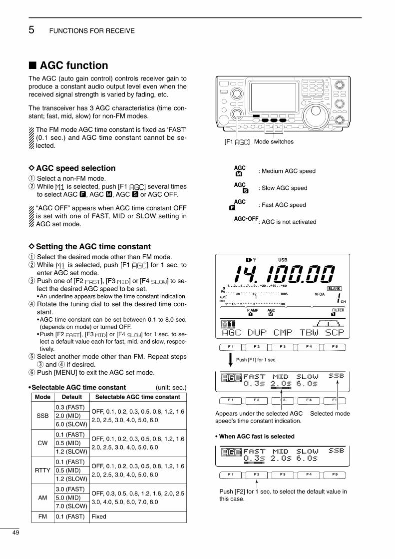
49
5 FUNCTIONS FOR RECEIVE
2001 NEW 2001 NEW
AGC functionThe AGC (auto gain control) controls receiver gain toproduce a constant audio output level even when thereceived signal strength is varied by fading, etc.
The transceiver has 3 AGC characteristics (time con-stant; fast, mid, slow) for non-FM modes.
The FM mode AGC time constant is fixed as ‘FAST’(0.1 sec.) and AGC time constant cannot be se-lected.
DDAGC speed selectionq Select a non-FM mode.w While M1 is selected, push [F1 AGC] several times
to select AGC F, AGC M, AGC S or AGC OFF.
“AGC OFF” appears when AGC time constant OFFis set with one of FAST, MID or SLOW setting inAGC set mode.
DDSetting the AGC time constantq Select the desired mode other than FM mode.w While M1 is selected, push [F1 AGC] for 1 sec. to
enter AGC set mode.e Push one of [F2 FAST], [F3 MID] or [F4 SLOW] to se-
lect the desired AGC speed to be set.•An underline appears below the time constant indication.
r Rotate the tuning dial to set the desired time con-stant.•AGC time constant can be set between 0.1 to 8.0 sec.(depends on mode) or turned OFF.
•Push [F2 FAST], [F3 MID] or [F4 SLOW] for 1 sec. to se-lect a default value each for fast, mid. and slow, respec-tively.
t Select another mode other than FM. Repeat stepse and r if desired.
y Push [MENU] to exit the AGC set mode.
•Selectable AGC time constant (unit: sec.)Mode Default Selectable AGC time constant
0.3 (FAST)OFF, 0.1, 0.2, 0.3, 0.5, 0.8, 1.2, 1.6
SSB 2.0 (MID)2.0, 2.5, 3.0, 4.0, 5.0, 6.0
6.0 (SLOW)
0.1 (FAST)OFF, 0.1, 0.2, 0.3, 0.5, 0.8, 1.2, 1.6
CW 0.5 (MID)2.0, 2.5, 3.0, 4.0, 5.0, 6.0
1.2 (SLOW)
0.1 (FAST)OFF, 0.1, 0.2, 0.3, 0.5, 0.8, 1.2, 1.6
RTTY 0.5 (MID)2.0, 2.5, 3.0, 4.0, 5.0, 6.0
1.2 (SLOW)
3.0 (FAST)OFF, 0.3, 0.5, 0.8, 1.2, 1.6, 2.0, 2.5
AM 5.0 (MID)3.0, 4.0, 5.0, 6.0, 7.0, 8.0
7.0 (SLOW)
FM 0.1 (FAST) Fixed
[F1 AGC] Mode switches
: Medium AGC speed
: Slow AGC speed
: Fast AGC speed
: AGC is not activated
F 1 F 2 F 3 F 4 F 5
F 1 F 2 F 3 F 4 F 5
F 1 F 2 F 3 F 4 F 5
AGC DUP CMP TBW SCP
Push [F1] for 1 sec.
Selected modeAppears under the selected AGC speed’s time constant indication.
Push [F2] for 1 sec. to select the default value in this case.
• When AGC fast is selected
IC-746PRO.qxd 02.4.2 11:31 Page 49

50
5FUNCTIONS FOR RECEIVE
2001 NEW
IF filter selectionThe transceiver has 3 passband width IF filters foreach mode.
For SSB and CW modes, the passband width can beset within 50 to 3600 Hz in 50 or 100 Hz steps. A totalof 41 passband widths are available.
For RTTY mode, the passband width can be set within50 to 2700 Hz in 50 or 100 Hz steps. A total of 32passband widths are available.
For AM and FM modes, the passband width is fixedand 3 passband widths are available independently.
The filter selection is automatically memorized ineach mode.
The PBT shift frequencies are automatically memo-rized in each filter.
DD IF filter selectionq Select the desired mode.w For RTTY mode, turn OFF the RTTY filter.e Push [FILTER] several times to select the IF filter
1, 2 or 3.•The selected passband width and filter number is dis-played in the LCD.
By pushing [PBTC], the set filter passband width,“B,” and shifting value “S” is indicated.
DDFilter passband width setting (SSB, CW and RTTY mode only)q Select SSB, CW or RTTY mode.
•Passband widths for AM and FM modes are fixed andcannot be set.
w For RTTY mode, turn OFF the RTTY filter.e Push [FILTER] for 1 sec. to enter filter set mode.r Push [FILTER] several times to select the desired
IF filter number.t While pushing [F1 BW], rotate the tuning dial to set
the desired passband width.• In SSB and CW modes, the passband width can be setwithin the following range.
50 to 500 Hz 50 Hz steps600 to 3600 Hz 100 Hz steps
• In RTTY mode, the passband width can be set within thefollowing range.
50 to 500 Hz 50 Hz steps600 to 2700 Hz 100 Hz steps
•Push [F-3] for 1 sec. to select the default value.y Repeat steps r to t if desired.u Push [MENU] to exit the filter set mode.
The PBT shift frequencies are cleared when thepassband width is changed.
This filter set mode screen graphically displays thePBT shift frequencies and CW pitch operations.
AGC DUP CMP TBW SCP
[FILTER]
The selected filter width is indicatedfor approx. 1 sec. when [FILTER] ispushed. Filter selection
BW
• Filter set mode indication
Shows the selected filter and passband width.
BW
• Indication while setting
While pushing [F1 BW], rotate the tuning dial to setpassband width.
Reverses Appears
IC-746PRO.qxd 02.4.2 11:31 Page 50

51
5 FUNCTIONS FOR RECEIVE
2001 NEW 2001 NEW
[NB]
NB Level5O%
Shows noise blanker level
“NB” appears while noise blanker is activated.
IF (DSP) filter shapeThe type of IF (DSP) filter shape for SSB and CW canbe selected independently from soft and sharp.
q Push [SSB] or [CW/RTTY] to select SSB, CW orRTTY mode.
w Select the filter set mode.•Push [FILTER] for 1 sec.•Operating mode can be selected in this step.
e Push [FILTER] several times to select the desiredIF filter.
r Push the [F5] to select the filter shape from “SOFT”and “SHARP.”
t Push [MENU] to exit the set mode.
Noise blankerThe noise blanker eliminates pulse-type noise such asfrom car ignitions. The noise blanker is not availablefor FM mode.
q Push [NB] to turn the noise blanker ON.• [NB] indicator appears.
w Push [NB] for 1 sec. to enter the NB level set mode.e Rotate the tuning dial to adjust the noise blanker
level.•Noise blanker level is indicated with bar meter and digitin ‘%.’
r Push [NB] to exit the noise blanker set mode.t Push [NB] to turn the noise blanker OFF.
• [NB] indicator disappears.
When using the noise blanker, received signals maybe distorted if the noise blanker level setting hasbeen too high.
Meter peak hold functionThe S-meter has a peak level holding function. Thepeak level of the received signal strength is indicatedfor 0.5 sec. (approx.). This function can be deactivatedin set mode if desired. (p. 82)
BW
BW
Push [F5]
Meter Peak Hold9 ON
Shows peak level for approx. 0.5 sec.
IC-746PRO.qxd 02.4.2 11:31 Page 51

52
5FUNCTIONS FOR RECEIVE
2001 NEW
Twin PBT operationGeneral PBT (Passband Tuning) function electronicallynarrows the IF passband width by shifting the IF fre-quency to slightly outside of the IF filter passband toreject interference. This transceiver uses the DSP cir-cuit for the PBT function. Moving both [TWIN PBT]controls to the same position shifts the IF.
The LCD shows the passband width and shift fre-quency graphically.
Push [FILTER] for 1 sec. to enter the filter set mode.Current passband width and shift frequency is dis-played in the filter set mode screen.
To set the [TWIN PBT] controls to the center posi-tions, push [PBTC] for 1 sec.
The variable range depends on the passband widthand mode. The edge of the variable range is half of thepassband width, and PBT is adjustable in 25 or 50 Hzsteps. These controls function as an IF shift controlwhile in AM mode and when the RTTY filter is turnedON. Only the inner control may function in this case.IF shift is adjustable in 20/40 Hz steps in RTTY (RTTYfilter is turned ON) or 150/300/500 Hz steps in AM.
• [TWIN PBT] should normally be set to the center positions(PBT setting is cleared) when there is no interference.NOTE: In the “center” PBT position on CW, it it normalfor the graphic display’s center line to be slightly to theleft side of PBT envelope, if a CW filter selection of800 Hz or above is selected.
•When PBT is used, the audio tone may be changed.•Not available for FM mode.•For AM and RTTY (with RTTY filter ON) modes,[TWIN PBT] inner control only can be activated, andfunctions as an IF shift function.
•While rotating [TWIN PBT], noise may occur. This comesfrom the DSP unit and does not indicate an equipmentmalfunction.
•By pushing [PBTC] momentarily indicates the passbandwidth, “B,” and shifting value, “S” of the filter being used.
PBT OPERATION EXAMPLE
interferenceinteferenceinterference desired signaldesired signal
pass band
IF center frequency
Center Passband Passband
IF center freq.
IF shift
AGC DUP CMP TBW SCP
Passband width and shifting value areindicated while [TWIN PBT] is operated.
[TWIN PBT] control
[PBTC]
Appears when PBT is used.
BW
• Filter set mode indication
Shows the selected filter and passband width.
BW
• Indication while PBT setting
Appears when passband is shifted.*By pushing [PBTC] for 1 sec., the shifted value returns to the default setting, and the “dot” disappears.
IC-746PRO.qxd 02.4.2 11:31 Page 52

53
5 FUNCTIONS FOR RECEIVE
2001 NEW
Noise reductionThe noise reduction function reduces noise compo-nents and picks out desired signals which are buriedin noise. The received signals are converted to digitalsignals and then the desired signals are separatedfrom the noise.
q Push the [NR] switch to turn the noise reductionON.• “NR” appears.
w Rotate the [NR] control to adjust the noise reductionlevel.
e Push the [NR] switch to turn the noise reductionOFF.• “NR” disappears.
Deep rotation of the [NR] control results in audio sig-nal masking or distortion. Set the [NR] control formaximum readability.
Notch functionThis transceiver has auto and manual notch functions.The auto notch function automatically attenuates morethan 3 beat tones, tuning signals, etc., even if they aremoving. The manual notch can be set to attenuate afrequency via the [NOTCH] control.
Push [A/NOTCH] to toggle the notch function be-tween auto, manual and OFF in SSB and AMmodes.
Push [A/NOTCH] to turn the manual notch functionON and OFF in CW mode.
Push [A/NOTCH] to turn the auto notch function ONand OFF in FM mode.•Set to attenuate a frequency for manual notch via the[NOTCH] control.
• “ANOTCH” appears when auto notch is in use.• “NOTCH” appears when manual notch is in use.
While operating the manual notch, noise may beheard. This comes from the DSP unit and does notindicate an equipment malfunction.
Dial lock functionThe dial lock function prevents accidental changescaused by the tuning dial.
Push [LOCK/SPCH] to turn the dial lock function ONand OFF.• “LOCK” indicator lights while the dial lock function is ac-tivated.
AGC DUP CMP TBW SCP
[A/NOTCH] [NOTCH]
Notch function indicators
AGC DUP CMP TBW SCP
[NR] [NR]
Appears
[LOCK/SPCH]
Lights while the dial lock function is activated.
IC-746PRO.qxd 02.4.2 11:31 Page 53

54
5FUNCTIONS FOR RECEIVE
Voice squelch control functionThis function is useful when you don’t want unmodu-lated signals. When the voice squelch control functionis activated, the receiver checks received signals forvoice components.
If a receiver signal includes voice components, and thetone of the voice components changes within 1 sec.,squelch opens. If the received signal includes no voicecomponents or the tone of the voice components doesnot change within 1 sec., squelch closes.
While M2 is selected with [MENU], push [F5 VSC]to switch the VSC (Voice Squelch Control) functionON and OFF.• “VSC” appears when the function is activated.
•The VSC function activates for phone modes(SSB, AM and FM).
•The VSC function can also be used for scanningoperation in AM or FM mode (p. 70).
F 1 F 2 F 3 F 4 F 5
SCN MEM SWR TCN VSC
Push [F5] to turn the VSC function ON and OFF.
VSC indicator
IC-746PRO.qxd 02.4.2 11:31 Page 54

6
55
FUNCTIONS FOR TRANSMIT
2001 NEW
VOX functionThe VOX (Voice-Operated Transmission) functionswitches between transmit and receive with your voice.This function provides an opportunity to input log en-tries into your computer, etc., while operating.
•Using the VOX functionq Select a phone mode (SSB, AM, FM).w Push [VOX/BK-IN] to turn the VOX function ON or
OFF.
DDAdjusting the VOX functionq Select a phone mode (SSB, AM, FM).w Push [VOX/BK-IN] to turn VOX function ON.e Push [VOX/BK-IN] for 1 sec. to enter VOX set
mode.r Select the VOX Gain item using [F1 ≤] or [F2 ≥]. t While speaking into the microphone, rotate the tun-
ing dial to the point where the transceiver is contin-uously transmitting.-Push [F3] for 1 sec. to select the default value.
y Push [F2 ≥] to select Anti-VOX item. u While receiving, rotate the tuning dial to the point
where the transceiver does not switch to transmitwith the speaker output.-Push [F3] for 1 sec. to select the default value.
i Push [F2 ≥] to select VOX Delay item. o Adjust the VOX delay for a convenient interval be-
fore returning to receive.-Select the VOX delay item using the tuning dial.-Push [F3] to select the default value.
!0 Push [MENU] to return to previous indication.
AGC DUP CMP TBW SCP
[VOX/BK-IN]
Appears
F 1 F 2 F 3 F 4 F 5
F 1 F 2 F 3 F 4 F 5
F 1 F 2 F 3 F 4 F 5
VOX Gain5O%
Shows VOX gain level
1
Anti-VOX5O%
Shows anti-VOX gain level
2
VOX DelayO.2s
Shows VOX delay time
3
IC-746PRO.qxd 02.4.2 11:31 Page 55
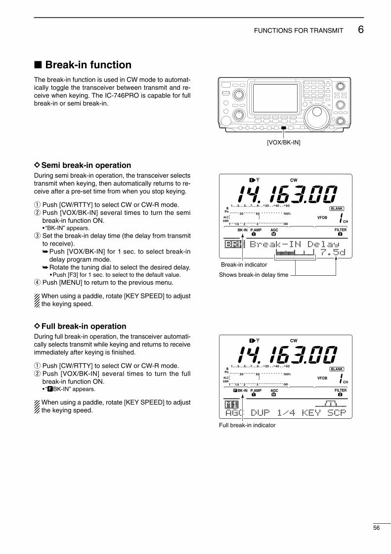
56
6FUNCTIONS FOR TRANSMIT
Break-in functionThe break-in function is used in CW mode to automat-ically toggle the transceiver between transmit and re-ceive when keying. The IC-746PRO is capable for fullbreak-in or semi break-in.
DDSemi break-in operationDuring semi break-in operation, the transceiver selectstransmit when keying, then automatically returns to re-ceive after a pre-set time from when you stop keying.
q Push [CW/RTTY] to select CW or CW-R mode.w Push [VOX/BK-IN] several times to turn the semi
break-in function ON.• “BK-IN” appears.
e Set the break-in delay time (the delay from transmitto receive).Push [VOX/BK-IN] for 1 sec. to select break-in
delay program mode.Rotate the tuning dial to select the desired delay.
•Push [F3] for 1 sec. to select to the default value.r Push [MENU] to return to the previous menu.
When using a paddle, rotate [KEY SPEED] to adjustthe keying speed.
DDFull break-in operationDuring full break-in operation, the transceiver automati-cally selects transmit while keying and returns to receiveimmediately after keying is finished.
q Push [CW/RTTY] to select CW or CW-R mode.w Push [VOX/BK-IN] several times to turn the full
break-in function ON.• “FBK-IN” appears.
When using a paddle, rotate [KEY SPEED] to adjustthe keying speed.
[VOX/BK-IN]
Break-IN Delay
Break-in indicator
Shows break-in delay time
7.5d
AGC DUP 1/4 KEY SCP
Full break-in indicator
IC-746PRO.qxd 02.4.2 11:31 Page 56

57
6 FUNCTIONS FOR TRANSMIT
2001 NEW 2001 NEW
∂∂TX functionThe ∂TX function shifts the transmit frequency up to±9.99 kHz in 10 Hz steps without moving the receivefrequency.•See #2 on p. 4 for function description.
q Push the [∂TX] switch to turn the ∂TX function ONand OFF.• “∂TX” and shift frequency appear when the function isON.
w Rotate the [RIT/∂TX] control.•To reset the ∂TX frequency, push [CLEAR] for 1 sec.•Push [CLEAR] momentarily to reset the ∂TX frequencywhen the quick RIT clear function is ON. (p. 86)
•To add or subtract the ∂TX frequency to the displayedfrequency, push [∂TX] for 1 sec.
When RIT and ∂TX are ON at the same time, the[RIT/∂TX] control shifts both the transmit and re-ceive frequencies from the displayed frequency atthe same time.
DD∂∂TX monitor functionWhen the ∂TX function is ON, pushing and holding[XFC] allows you to monitor the operating frequency di-rectly (∂TX is temporarily cancelled).
Monitor functionThe monitor function allows you to monitor your trans-mit IF signals in any mode through the speaker. Usethis to check voice characteristics while adjusting SSBtransmit tones. (p. 89) The CW sidetone functions re-gardless of the [MONITOR] switch setting.
q Push [MONITOR] to switch the monitor function ONand OFF.• “MONI” appears when the monitor function is ON.
w Set the monitor level.Push [MONITOR] for 1 sec. to select monitor pro-
gram mode.Rotate the tuning dial for the clearest audio out-
put while pushing [PTT] and speaking into the mi-crophone.•Push [F3] for 1 sec. to select the default value.
e Push [MENU] to return to the previous menu.
[∂TX]
[CLEAR]
[RIT/∂TX] control
Appears
[MONITOR]
MONITOR Level
Monitor indicator
Shows monitor level
5O%
IC-746PRO.qxd 02.4.2 11:31 Page 57

58
6FUNCTIONS FOR TRANSMIT
2001 NEW
Speech compressorThe speech compressor increases average RF outputpower, improving signal strength and readability inSSB, AM or FM. When adjusting the compression level, it is necessaryto turn the COMP meter ON in the set mode, in ad-vance (p. 82).
• In SSB modeq Select USB or LSB mode and adjust [MIC GAIN] to
a suitable level.w While M1 is selected, push [F3 CMP] to turn the
speech compressor ON.• “COMP” appears.
e Push [F3 CMP] for 1 sec. to select compressionlevel set mode.
r While speaking into the microphone, rotate the tun-ing dial, so that the COMP meter reads within theCOMP zone with your normal voice level.•Push [F3] for 1 sec. to select the default value.
When the COMP meter peaks above the COMPzone, your transmitted voice may be distorted.
t Push [MENU] to return to M1.
• In AM/FM modeq While M1 is selected, push [F3 CMP] to turn the
speech compressor ON.• “COMP” appears.
w Push [F3 CMP] for 1 sec. and set the compressionlevel as “1” in advance.
e While speaking into the microphone, rotate [MICGAIN], so that the COMP meter does not exceedthe center dot whether you speak softly or loudly.
r While speaking into the microphone, rotate the tun-ing dial, so that the COMP meter reads within theCOMP zone with your normal voice level.•Push [F3] for 1 sec. to select the default value.
When the COMP meter peaks above the COMPzone, your transmitted voice may be distorted.
t Push [MENU] to return to M1.
Transmit filter width selection (SSB mode only)
The transmit filter width for SSB mode can be selectedfrom wide, middle and narrow.
q Select USB or LSB mode.w Push [MENU] to select M1, if necessary.e Push [F4 TBW] for 1 sec. to select the transmission
passband width.•One of “TX BW=WIDE,” “TX BW=MID” or “TXBW=NAR” is displayed for approx. 1 sec.
•Transmit filter width: NAR 2.2 kHzMID 2.4 kHzWIDE 2.8 kHz
COMP Level
COMP Level
5
1
Compressor indicator
Shows compression level
COMP level zone*The SWR meter functions as the COMP meter when COMP meter is set to ON in the set mode.
COMP meterALC meter
Adjust the COMP Level with the tuning dial so that the COMP meter does not exceed the COMP level zone.
Adjust [MIC GAIN], so that the COMP meter does not exceed this zone.
F 1 F 2 F 3 F 4 F 5
F 1 F 2 F 3 F 4 F 5
AGC DUP CMP TBW SCP
AGC DUP CMP TBW SCPTX BW=WIDE
Push [F4]
Push [F4] for 1 sec. to select the transmit filter width.
The selected transmit filter width is displayed for approx. 1 sec.
IC-746PRO.qxd 02.4.2 11:31 Page 58

59
6 FUNCTIONS FOR TRANSMIT
2001 NEW 2001 NEW
Split frequency operationSplit frequency operation allows you to transmit andreceive in the same mode on two different frequencies.The split frequency operation is basically performedusing 2 frequencies in VFO A and VFO B.
The following is an example of setting 21.290 MHz forreceiving and 21.310 MHz for transmitting.
q Set 21.290 MHz (USB) in VFO A.w Push [SPLIT] to turn the split function ON, then
push [A/B] for 1 sec.•The equalized transmit (VFO B) frequency and “SPLIT”appear on the LCD, and the [SPLIT] indicator lights.
e While pushing [XFC] rotate the tuning dial to set thetransmit frequency to 21.310 MHz.•The transmit frequency can be monitored while pushing[XFC].
r Now you can receive on 21.290 MHz and transmiton 21.310 MHz.
To change the transmit and receive frequencies, push[A/B] to exchange the VFO A and VFO B.
Tuning dial[XFC]
[SPLIT] Lights during split operation
[A/B]
AppearsShows transmit (VFO B) frequency
AGC DUP CMP TBW SCP21.29OOO
Shows transmit (VFO B) frequencyShows shift frequency and direction
AGC DUP CMP TBW SCP+2O.OOk
• While pushing [XFC]
AGC DUP CMP TBW SCP21.31OOO
• After setting up
CONVENIENT
•Direct shift frequency inputThe shift frequency can be entered directly.
q Push [F-INP].w Enter the desired shift frequency with the digit
keys.•1 kHz to 1 MHz can be set.•When you require a minus shift direction, push[GENE • ] in advance.
e Push [SPLIT].•The shift frequency is input in the sub readout and thesplit function is turned ON.
[Example]To transmit on 1 kHz higher frequency:
- Push [F-INP], [1.8 1] then [SPLIT].To transmit on 3 kHz lower frequency:
- Push [F-INP], [GENE • ], [7 3] then [SPLIT].
•Split lock functionAccidentally releasing the [XFC] switch while rotatingthe tuning dial changes the receive frequency. To pre-vent this, use both the split lock and dial lock func-tions to change the transmit frequency only. The splitlock function cancels the dial lock function whilepushing [XFC] during split frequency operation.
The dial lock’s effectiveness during split frequencyoperation can be selected in the set mode for bothreceive and transmit frequencies; or only the receivefrequency. (p. 83)
IC-746PRO.qxd 02.4.2 11:31 Page 59

60
6FUNCTIONS FOR TRANSMIT
2001 NEW
Quick split functionWhen you push the [SPLIT] switch for 1 sec., split fre-quency operation is turned ON, the undisplayed VFOis automatically changed according to the plus/minusshift frequency programmed in set mode (p. 83) orequalized when 0 kHz (default value) is programmedas the split shift frequency. Quick split operation isturned ON by default but can be turned OFF in setmode (p. 83).
q Suppose you are operating at 21.290 MHz (USB) inVFO A.
w Push [SPLIT] for 1 sec.•Split frequency operation is turned ON.•The VFO and VFO B are equalized.
e While pushing [XFC], rotate the tuning dial to setthe frequency offset between transmit and receive.•When [XFC] is released, the receive frequency is indi-cated.
DDSplit offset frequency settingBy setting an often-used split frequency offset in ad-vance, you can use the quick split function to select splitoperation at the push of one switch.
Set the split offset frequency in advance in set mode(p. 83, item 12). The example at right shows the splitoffset is set to +0.020 MHz.
Push [SPLIT] for 1 sec. to activate the quick splitfunction.•The transmit frequency is offset from the receive fre-quency according to the offset in set mode.
DDSplit lock functionThe split lock function is convenient for changing onlythe transmit frequency. When the split lock function isnot used, accidentally releasing [XFC] while rotating thetuning dial, changes the receive frequency. The splitlock function is ON by default, but can be turned OFFin set mode.
q While split frequency operation is ON, push[LOCK/SPCH] to activate the split lock function.
w While pushing [XFC], rotate the tuning dial tochange the transmit frequency.• If you accidentally release [XFC] while rotating the tuningdial, the receive frequency does NOT change.
Shows shift frequency and direction
AGC DUP CMP TBW SCP+2O.OOk
• Setting the frequency while pushing [XFC]
AGC DUP CMP TBW SCP21.31OOO
12 +O.O2OMHzSPLIT Offset
Shows transmit frequency for split operation
13 OFFSPLIT LOCK
[XFC] Tuning dial [LOCK/SPCH]
IC-746PRO.qxd 02.4.2 11:31 Page 60

61
6 FUNCTIONS FOR TRANSMIT
2001 NEW 2001 NEW
Measuring SWR The IC-746PRO has a built-in circuit for measuring an-tenna SWR— no external equipment or special adjust-ments are necessary.
The IC-746PRO can measure SWR in 2 ways— spotmeasurement and plot measurement are available.
DDSpot measurementq Push [TUNER] to turn the antenna tuner OFF.w Turn the COMP meter OFF.
Push [MENU] for 1 sec. to enter set mode.Push [F1 ≤] or [F2 ≥] several times to select the
COMP Meter item.Rotate the tuning dial to set the COMP meter OFF.Push [MENU] to exit set mode.
e Push [CW/RTTY] several times to select RTTYmode.
r Push [TRANSMIT] or [PTT] on the microphone.t Rotate [RF PWR] clockwise past the 12 o’clock po-
sition for more than 30 W output power (30%).y Read the SWR on the SWR meter.u Push [TRANSMIT] or release [PTT] to receive.
The built-in antenna tuner matches the transmitterto the antenna when the SWR is lower than 3:1.
DDPlot measurementPlot measurement allows you to measure the SWRover an entire band.
q While M2 is selected with [MENU], push [F3 SWR].•SWR graph screen appears.
w Rotate [RF PWR] clockwise past the 12 o’clock po-sition for more than 30 W output power (30%).
e Set the center frequency for the SWR to be mea-sured.
r Push [F5] for 1 sec. several times to select the de-sired measuring step from 10, 50, 100 and 500 kHz.
t Push [F3] several times to select the desired num-ber of measuring steps from 3, 5, 7, 9, 11 and 13steps.
y Push [F1] to start the measuring.u Push [TRANSMIT] or push and hold [PTT] on the
microphone to measure the SWR.•Frequency marker, “∫,” appears below SWR graph.•RTTY mode is automatically selected.
i When pushing [TRANSMIT] again or releasing[PTT], the frequency marker and frequency indica-tion move to the next frequency to be measured.
o Repeat steps u and i to measure SWR over theentire frequency range.
!0 When the measured SWR is less than 1.5:1, theantenna is well matched with the transceiver in themeasured frequency range.
AGC DUP 1/4 RTY SCP
The best match is in this range.
F 1 F 2 F 3 F 4 F 5
F 1 F 2 F 3 F 4 F 5
SCN MEM SWR TCN VSC
1OkSTEP
1OkSTEP
Push [F3]
Push [F5] to select SWR measuring step.
Push [F3] to select number of SWR measuring steps.
Push [F1] to start measuring.
• Measuring (after pushing [F1])
Frequency marker appears and moves after meas-urement.*When mesurement point/s is/are set outside of the oper-atable frequency band, the frequency marker flashes.
Typical display SWR varying between 1 and 2, full scale up to SWR 4.0:1.
— 1.0:1
— 1.5:1
— 2.0:1— 3.0:1— 4.0:1
IC-746PRO.qxd 02.4.2 11:31 Page 61

7
62
MEMORY OPERATION
2001 NEW
Memory channelsThe transceiver has 101 memory channels (plus 1 callchannel). The memory mode is very useful for quicklychanging to often-used frequencies.
All 101 memory channels are tuneable which meansthe programmed frequency can be tuned temporarilywith the tuning dial, etc. in memory mode.
Memory channel selection
DD In VFO modeq Push [V/M] to select VFO mode, if necessary, then
rotate [M-CH] to select a memory channel number.•All memory channels including blank channels can beselected.
• “BLANK” appears when no information has been pro-grammed into a memory channel.
w Push [V/M] to select memory mode.• “MEMO” and contents of the memory channel appear.
DD In memory modeq Push [V/M] to select memory mode.w Rotate [M-CH] to select a memory channel.
•All memory channels including blank channels can beselected.
•Memory channels can also be selected using the micro-phone [UP]/[DN] keys.
[V/M] [M-CH]
Disappears when a channel is programmed.
• During VFO mode
• During memory mode
MEMORY MEMORY TRANSFER OVER-CHANNEL CHANNEL CAPABILITY TO VFO WRITING CLEAR
NUMBER
Regular memory 1–99 One frequency and one mode Yes Yes Yeschannels in each memory channel.
Scan edge One frequency and one mode inmemory P1, P2 each memory channel as scan Yes Yes Nochannels edges for programmed scan.
Call channel C Same as regular. No Yes No
IC-746PRO.qxd 02.4.2 11:31 Page 62

63
7 MEMORY OPERATION
2001 NEW 2001 NEW
Programming a memory Memory channel programming can be preformed ei-ther in VFO mode or in memory mode.
DDProgramming in VFO modeq Set the desired frequency and operating mode in
VFO mode.w Rotate [M-CH] to select the desired memory chan-
nel.• “BLANK” appears if the selected memory channel is ablank channel (and does not have contents).
e Push [MW] for 1 sec. to program the displayed fre-quency and operating mode into the memory chan-nel.•3 beeps are emitted when memory programming is suc-cessful.
DDProgramming in VFO modeq Select the desired memory channel with [M-CH] in
memory mode.•Memory channel contents appear in the display.• “BLANK” appears and no frequency readout is displayedif the selected memory channel is a blank channel (anddoes not have contents).
w Set the desired frequency and operating mode inmemory mode.•To program a blank channel, use direct frequency entrywith the keypad or memo pads, etc.
e Push [MW] for 1 sec. to program the displayed fre-quency and operating mode into the memory chan-nel.•3 beeps are emitted when memory programming is suc-cessful.
Memory clearingAny unnecessary memory channels can be cleared.The cleared memory channels become blank chan-nels.
q Select memory mode with [V/M].w Select the desired memory channel with [M-CH].e Push [M-CL] for 1 sec. to clear the contents.
•The programmed frequency and operating mode disap-pear.
•3 beeps are emitted when memory clearing is success-ful.
r To clear other memory channels, repeat steps wand e.
[V/M] [M-CH]
[MW]
AGC DUP CMP TBW SCP
• [EXAMPLE]: Programming 7.088 MHz/LSB into memory channel 12.
AGC DUP CMP TBW SCP
• [EXAMPLE]: Programming 21.280 MHz/USB into memory channel 18.
[V/M] [M-CH]
[M-CL]
IC-746PRO.qxd 02.4.2 11:31 Page 63

2001 NEW
64
7MEMORY OPERATION
Selecting the call channel By default 145.00000 MHz/FM is programmed into thecall channel. However, this can be changed to suityour operating preference. (see below)
q Push [CALL] to select the call channel.• “C” appears.
w Push [CALL] again to return to the previous mode.
Programming the call channelThe call channel is programmed in the same way reg-ular memory channels are. It’s convenient to programa most-often-used frequency into the call channel forquick recall. As with memory channels, the call chan-nel can also hold split frequencies.
q Rotate [M-CH] to select the call channel.• “C” appears.
w Select the desired frequency and operating modeto program into the call channel.
e Push [MW] for 1 sec. to program the displayed fre-quency and operating mode into the call channel.•3 beeps are emitted when memory programming is suc-cessful.
IMPORTANT!: When the call channel is selectedwith the [CALL] switch, the frequency CANNOT bechanged using the tuning dial, band keys or keypadinput. However, when the call channel is selectedusing [M-CH] in memory mode, the frequency CANbe changed.
[CALL]
AGC DUP CMP TON SCP
“C” appears
[V/M] [M-CH]
[MW]
AGC DUP CMP TON SCP
IC-746PRO.qxd 02.4.2 11:31 Page 64

65
7 MEMORY OPERATION
2001 NEW 2001 NEW
Frequency transferringThe contents of a memory channel (frequency, oper-ating mode, etc.) can be transferred to the VFO.
Frequency transferring can be performed in either VFOmode or memory mode.
DDTransferring in VFO modeThis is useful for transferring programmed contents toVFO.
q Select VFO mode with [V/M].w Select the memory channel to be transferred with
[M-CH].• “BLANK” appears if the selected memory channel is ablank channel. In this case transferring is impossible.
e Push [V/M] for 1 sec. to transfer the frequency andoperating mode.•3 beeps are emitted.
DDTransferring in memory modeThis is useful for transferring frequency and operatingmode while operating in memory mode.
When you have changed the frequency or operat-ing mode in the selected memory channel:•Displayed frequency and mode are transferred.•Programmed frequency and mode in the memorychannel are not transferred, and they remain in thememory channel.
q Select the memory channel to be transferred with[M-CH] in memory mode.•And, set the frequency or operating mode if required.
w Push [V/M] for 1 sec. to transfer the frequency andoperating mode.•3 beeps are emitted when the transferring is successful.•Displayed frequency and operating mode are transferredto the VFO.
e To return to VFO mode, push [V/M] momentarily.
[V/M] [M-CH]
TRANSFERRING EXAMPLE IN VFO MODEOperating frequency : 21.320 MHz/USB (VFO)Contents of M-ch 16 : 14.018 MHz/CW
Push [V/M] for 1 sec.
TRANSFERRING EXAMPLE IN MEMORY MODEOperating frequency : 14.020 MHz/CW (M-ch 16)Contents of M-ch 16 : 14.018 MHz/CW
Set the frequency
Push [V/M] for 1 sec.then push [V/M]
IC-746PRO.qxd 02.4.2 11:31 Page 65
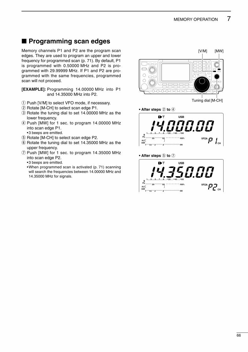
66
7MEMORY OPERATION
2001 NEW
Programming scan edgesMemory channels P1 and P2 are the program scanedges. They are used to program an upper and lowerfrequency for programmed scan (p. 71). By default, P1is programmed with 0.50000 MHz and P2 is pro-grammed with 29.99999 MHz. If P1 and P2 are pro-grammed with the same frequencies, programmedscan will not proceed.
[EXAMPLE]: Programming 14.00000 MHz into P1and 14.35000 MHz into P2.
q Push [V/M] to select VFO mode, if necessary.w Rotate [M-CH] to select scan edge P1.e Rotate the tuning dial to set 14.00000 MHz as the
lower frequency.r Push [MW] for 1 sec. to program 14.00000 MHz
into scan edge P1.•3 beeps are emitted.
t Rotate [M-CH] to select scan edge P2.y Rotate the tuning dial to set 14.35000 MHz as the
upper frequency.u Push [MW] for 1 sec. to program 14.35000 MHz
into scan edge P2.•3 beeps are emitted.•When programmed scan is activated (p. 71) scanningwill search the frequencies between 14.00000 MHz and14.35000 MHz for signals.
[V/M]
Tuning dial [M-CH]
[MW]
• After steps w to r
• After steps t to u
IC-746PRO.qxd 02.4.2 11:31 Page 66

67
7 MEMORY OPERATION
2001 NEW 2001 NEW
Assigning memory namesAll memory channels (including scan edges) can betagged with alphanumeric names of up to 9 characterseach.
[EXAMPLE]: Programming “DX spot” into memorychannel 99.
q Push [V/M] to select memory mode, if necessary.w Rotate [M-CH] to select memory channel 99.e Push [MENU] several times to select M2.r Push [F2 MEM] to select the memory name screen.t Push [F1 EDT] to edit memory channel name.
•A cursor appears and blinks.•Memory channel names of blank channels cannot beedited.
y Push [F1] several times to select the type of char-acters for input.• “ABC” inputs capital letters A to Z.• “abc” inputs small letters a to z.• “etc” is used to input other characters— ! # $ % & ¥ ? ”’ ` ^ + – / . , : ; = < > ( ) [ ] | _ – are available.
•Use the keypad to directly input numerals, “0” to “9,” in-cluding a decimal point.
u Rotate the tuning dial to select the first character forinput.
i Push [F2 ç] or [F3 å] to move the cursor forwardsor backwards, respectively. •Push [F5 SPC] to input a space and [F4 DEL] to deletethe selected character.
o Repeat steps w to i to program another memorychannel’s name, if desired.
!0 Push [MENU] to set the memory channel name andreturn to the memory name menu.•Push [MENU] 1 more times to return to M2.
[V/M]
Tuning dial [M-CH][MENU]
F 1 F 2 F 3 F 4 F 5
F 1 F 2 F 3 F 4 F 5
F 1 F 2 F 3 F 4 F 5
F 1 F 2 F 3 F 4 F 5
F 1 F 2 F 3 F 4 F 5
SCN MEM SWR TCN VSC
EDT ( ) SEL14.195OO USB
ABC DEL SPC
Push [F2 MEM]
Push [F2 MEM]
ABC DEL SPCDX
• During assigning a memory name
abc DEL SPCDX spot
• After assigning a memory name
Input spaceDelete a character
Move cursor forwardsMove cursor backwards
Selects character type
IC-746PRO.qxd 02.4.2 11:31 Page 67
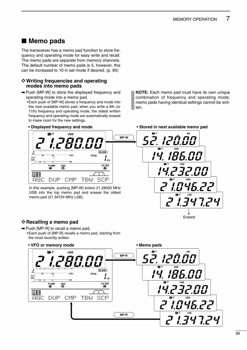
68
7MEMORY OPERATION
2001 NEW
Memo padsThe transceiver has a memo pad function to store fre-quency and operating mode for easy write and recall.The memo pads are separate from memory channels.The default number of memo pads is 5, however, thiscan be increased to 10 in set mode if desired. (p. 85)
DDWriting frequencies and operatingmodes into memo pads
Push [MP-W] to store the displayed frequency andoperating mode into a memo pad.•Each push of [MP-W] stores a frequency and mode intothe next available memo pad; when you write a 6th (or11th) frequency and operating mode, the oldest writtenfrequency and operating mode are automatically erasedto make room for the new settings.
DDRecalling a memo padPush [MP-R] to recall a memo pad.
•Each push of [MP-R] recalls a memo pad, starting fromthe most recently written.
NOTE: Each memo pad must have its own uniquecombination of frequency and operating mode;memo pads having identical settings cannot be writ-ten.
AGC DUP CMP TBW SCP
MP-W
Erased
In this example, pushing [MP-W] enters 21.28000 MHz USB into the top memo pad and erases the oldest memo pad (21.34724 MHz LSB).
• Displayed frequency and mode • Stored in next available memo pad
AGC DUP CMP TBW SCP
• VFO or memory mode • Memo pads
MP-R
MP-R
IC-746PRO.qxd 02.4.2 11:31 Page 68

8
69
SCANS
2001 NEW
Scan types
Preparation•ChannelsFor programmed scan: Program scan edge frequencies into scan edge mem-ory channels P1 and P2.
For ∂∂F scan: Set the ∂F span (∂F scan range) in the scan screen.
For memory scan: Program 2 or more memory channels except scanedge memory channels.
For select memory scan: Designate 2 or more memory channels as select mem-ory channels. To designate the channel as a selectmemory channel, choose a memory channel, thenpush [F3 SEL] in the scan screen, or push [F5 SEL]in the memory name screen.
•Scan resume ON/OFFYou can select the scan to resume or cancel when de-tecting a signal, in set mode. Scan resume ON/OFFmust be set before operating a scan. See p. 70 forON/OFF setting and scan resume condition details.
•Scan speedScan speed can be selected from 2 levels, high or low,in set mode. See p. 70 for details.
•Squelch condition
PROGRAMMED SCANRepeatedly scans between two scan edge frequencies (scan edge memory channels P1 and P2).
This scan operates in VFO mode.
SELECT MEMORY SCANRepeatedly scans all selected memory channels.
∂F SCANRepeatedly scans within ∂F span area.
This scan operates in memory mode.This scan operates in memory mode.
This scan operates in both VFO and memory modes.
Scan
Scan edge P1 or P2
Scan edge P2 or P1
Jump
Mch 1 Mch 5
Mch 2 Mch 3 Mch 4
Mch 6Mch 7Mch 99
MEMORY SCANRepeatedly scans all programmed memory channels.
Mch 1 Mch 5
Mch 2 Mch 3 Mch 4
Mch 6Mch 7Mch 99
SEL
SELSEL
SEL SEL
SEL
SELSEL
SEL SEL
ScanScan
–∂F frequency +∂F frequency
Start frequency
Jump
SQUELCHCLOSED
SQUELCHOPEN
Scan stops when detecting a signal.
If you set scan resume ON in scan setmode, the scan pauses for 10 sec. whendetecting a signal, then resumes. When asignal disappears while scan is paused,scan resumes 2 sec. later.
The scan continuesuntil it is stoppedmanually, and doesnot pause even if itdetects signals.
Scan pauses oneach channel whenthe scan resume isON; not applicablewhen OFF.
SCAN PROGRAMMEDSTARTS SCAN MEMORY SCANWITH
IC-746PRO.qxd 02.4.2 11:31 Page 69

70
8SCANS
Voice squelch control functionThis function is useful when you don’t want unmodu-lated signals pausing or cancelling a scan. When thevoice squelch control function is activated, the receiverchecks received signals for voice components.
If a receiver signal includes voice components, and thetone of the voice components changes within 1 sec.,scan pauses (or stops). If the received signal includesno voice components or the tone of the voice compo-nents does not change within 1 sec., scan resumes.
While M2 is selected with [MENU], push [F5 VSC]to switch the VSC (Voice Squelch Control) functionON and OFF.• “VSC” appears when the function is activated.
•The VSC function activates for any scan.•The VSC function resumes the scan on unmodu-lated signals, regardless of whether the scan re-sume condition is set to ON or OFF.
Scan set modeWhen the squelch is open, scan continues until it isstopped manually— it does not pause on detected sig-nals. When squelch is closed, scan stops when de-tecting a signal, then resumes according to the scanresume condition. Scan speed and the scan resumecondition can be set using the scan set mode.
q Push[MENU] to select M2.w Push [F1 SCN] to select scan menu.e Push [F5 SET] to select scan set mode.r Push [F1 ≤] or [F2 ≥] to select SCAN Speed
item.t Rotate the tuning dial to select scan speed from
high and low.• “HIGH” : scan is faster• “LOW” : scan is slower
y Push [F2 ≥] to select SCAN Resume item.u Rotate the tuning dial to select scan resume func-
tion from ON and OFF.• “ON” : when detecting a signal, scan pauses for
10 sec., then resumes. When a signal disap-pears, scan resumes 2 sec. later.
• “OFF” : when detecting a signal, cancels scanning.i Push [MENU] to return to scan menu.
F 1 F 2 F 3 F 4 F 5
F 1 F 2 F 3 F 4 F 5
F 1 F 2 F 3 F 4 F 5
F 1 F 2 F 3 F 4 F 5
SCN MEM SWR TCN VSC
PRO ∂F FIN SPN SET∂F:±1Ok
Push [F1]
Push [F5]
SCAN SpeedHIGH1
Push [F1] or [F2]
SCAN ResumeON2
F 1 F 2 F 3 F 4 F 5
SCN MEM SWR TCN VSC
Push [F5] to turn the VSC function ON and OFF.
VSC indicator
IC-746PRO.qxd 02.4.2 11:31 Page 70

71
8 SCANS
2001 NEW 2001 NEW
Programmed scan/Fine programmed scan (VFO mode)Programmed scan searches for signals between scanedge memory channels P1 and P2. The default fre-quencies for these memories are 0.500000 MHz and29.99999 MHz, respectively. See p. 66 for scan edgesprogramming.
q Push [V/M] to select VFO mode, if necessary.w Select the desired operating mode.
•The operating mode can also be changed while scan-ning.
e Push [TS] to select a tuning step.•The tuning step can also be changed while scanning.
r Push [MENU] to select M2.t Push [F1 SCN] to select the scan menu.
•See p. 69 for scan condition.• If the [RF/SQL] control function is set as “AUTO,” thesquelch is always open in SSB, CW and RTTY modes.yPush [F1 PRO] to start the programmed scan.
•The MHz and kHz decimal points blink while scanning.u When the scan detects a signal, the scan stops,
pauses or ignores it depending on the resume, VSCsetting and the squelch condition.
i To cancel the scan, push [F1 PRO].•Rotating the tuning dial during scan also cancels scanoperation.
If the same frequencies are programmed into thescan edge memory channel P1 and P2, pro-grammed scan does not start.
DDAbout the Fine programmed scanDuring programmed scan, when a signal is received,scan continues, but the tuning step is temporarily set to10 Hz.
q Follow steps q to y above to start programmedscan.
w During programmed scan, push [F3 FIN] to switchbetween programmed scan and fine programmedscan operation.
e Push [F1 PRO] to cancel the scan.•Rotating the tuning dial during scan also cancels scanoperation.
[TS]
Tuning dial[MENU]
[V/M]
Mode keys
F 1 F 2 F 3 F 4 F 5
F 1 F 2 F 3 F 4 F 5
F 1 F 2 F 3 F 4 F 5
SCN MEM SWR TCN VSC
PRO ∂F FIN SPN SET∂F:±1Ok
PRO ∂F FIN SPN SETPROG SCAN
Push [F1]
Push [F1] to start/cancel the scanning.
Push [F1]
F 1 F 2 F 3 F 4 F 5
F 1 F 2 F 3 F 4 F 5
PRO ∂F FIN SPN SETPROG SCAN
PRO ∂F FIN SPN SETF-PROG SCAN
Push [F3] to switch between programmed scan and fine pro-grammed scan.
IC-746PRO.qxd 02.4.2 11:31 Page 71
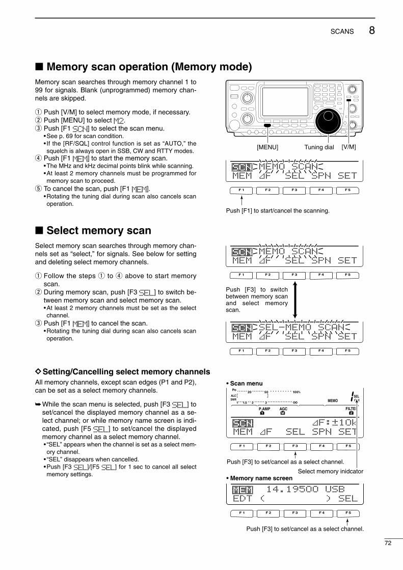
72
8SCANS
2001 NEW
Memory scan operation (Memory mode)Memory scan searches through memory channel 1 to99 for signals. Blank (unprogrammed) memory chan-nels are skipped.
q Push [V/M] to select memory mode, if necessary.w Push [MENU] to select M2.e Push [F1 SCN] to select the scan menu.
•See p. 69 for scan condition.• If the [RF/SQL] control function is set as “AUTO,” thesquelch is always open in SSB, CW and RTTY modes.
r Push [F1 MEM] to start the memory scan.•The MHz and kHz decimal points blink while scanning.•At least 2 memory channels must be programmed formemory scan to proceed.
t To cancel the scan, push [F1 MEM].•Rotating the tuning dial during scan also cancels scanoperation.
Select memory scan Select memory scan searches through memory chan-nels set as “select,” for signals. See below for settingand deleting select memory channels.
q Follow the steps q to r above to start memoryscan.
w During memory scan, push [F3 SEL] to switch be-tween memory scan and select memory scan.•At least 2 memory channels must be set as the selectchannel.
e Push [F1 MEM] to cancel the scan.•Rotating the tuning dial during scan also cancels scanoperation.
DDSetting/Cancelling select memory channelsAll memory channels, except scan edges (P1 and P2),can be set as a select memory channels.
While the scan menu is selected, push [F3 SEL] toset/cancel the displayed memory channel as a se-lect channel; or while memory name screen is indi-cated, push [F5 SEL] to set/cancel the displayedmemory channel as a select memory channel.• “SEL” appears when the channel is set as a select mem-ory channel.
• “SEL” disappears when cancelled.•Push [F3 SEL]/[F5 SEL] for 1 sec to cancel all selectmemory settings.
Tuning dial[MENU] [V/M]
F 1 F 2 F 3 F 4 F 5
MEM ∂F SEL SPN SETMEMO SCAN
Push [F1] to start/cancel the scanning.
F 1 F 2 F 3 F 4 F 5
F 1 F 2 F 3 F 4 F 5
MEM ∂F SEL SPN SETMEMO SCAN
MEM ∂F SEL SPN SETSEL-MEMO SCAN
Push [F3] to switch between memory scan and select memory scan.
F 1 F 2 F 3 F 4 F 5
F 1 F 2 F 3 F 4 F 5
∂F:±1OkMEM ∂F SEL SPN SET
Push [F3] to set/cancel as a select channel.
Select memory inidcator
Push [F3] to set/cancel as a select channel.
EDT ( ) SEL14.195OO USB
• Scan menu
• Memory name screen
IC-746PRO.qxd 02.4.2 11:31 Page 72

73
8 SCANS
2001 NEW 2001 NEW
∂∂F scan operation and Fine ∂F scan∂F scan searches for signals within the specifiedrange with the displayed VFO or memory channel fre-quency as for center frequency. The frequency rangeis specified by the span.
q Push [V/M] to select VFO mode or memory mode,as desired.
w Set center frequency of the ∂F scan.e Push [MENU] to select M2.r Push [F1 SCN] to select the scan menu.
•See p. 69 for scan condition.• If the [RF/SQL] control function is set as “AUTO,” thesquelch is always open in SSB, CW and RTTY modes.
t Set the ∂F span by pushing [F4 SPN].•±5 kHz, ±10 kHz, ±20 kHz, ±50 kHz, ±100 kHz,±500 kHz and ±1 MHz are selectable.
y Push [F2 ∂F] to start the ∂F scan.•Decimal points blink while scanning.
u When the scan detects a signal, the scan stops,pauses or ignores it depending on the VSC, resumesetting and the squelch condition.
i Push [F2 ∂F] to cancel the ∂F scan.•Rotating the tuning dial during scan also cancels scanoperation.
DDAbout the Fine ∂∂F scanDuring ∂F scan, when a signal is received, scan con-tinues, but the tuning step is temporarily set to 10 Hz.
q Follow steps q to y above to start programmedscan.
w During ∂F scan, push [F3 FIN] to switch between∂F scan and fine ∂F scan operation.
e Push [F2 ∂F] to cancel the scan.•Rotating the tuning dial during scan also cancels scanoperation.
Keypad
Tuning dial[MENU]
[V/M]
F 1 F 2 F 3 F 4 F 5
F 1 F 2 F 3 F 4 F 5
F 1 F 2 F 3 F 4 F 5
SCN MEM SWR TCN VSC
PRO ∂F FIN SPN SET∂F:±1Ok
PRO ∂F FIN SPN SET∂F SCAN
Push [F1]
Push [F2] to start/cancel the scanning.
Push [F2]Push [F4] to select the span.
F 1 F 2 F 3 F 4 F 5
F 1 F 2 F 3 F 4 F 5
PRO ∂F FIN SPN SET∂F SCAN
PRO ∂F FIN SPN SETF-∂F SCAN
Push [F3] to switch between programmed scan and fine pro-grammed scan.
IC-746PRO.qxd 02.4.2 11:31 Page 73

74
8SCANS
2001 NEW
Tone scan/DTCS code scan operationBy monitoring a signal that is being operated with a re-peater, tone squelch or DTCS, you can determine thetone frequency necessary to open a repeater or thesquelch.
qPush [AM/FM] to select FM mode.wPush [MENU] several times to select M1.ePush [F4 TONE] for 1 sec. to enter tone set mode.rPush [F1 TON] to select the tone type to be
scanned.• “Rptr Tone” for repeater tone, “TSQL Tone” fortone squelch and “DTCS Code” for DTCS code can beselected.
•When selecting DTCS code to be scanned, push [F5]several times to select the DTCS code polarity.“NN” : Normal polarity for both transmit and receive.“NR” : Normal polarity for transmit and reverse polarity
for receive.“RN” : Reverse polarity for transmit and normal polarity
for receive.“RR” : Reverse polarity for both transmit and receive.
tPush [F2 SCN] to start the tone scan function.• “Rptr Tone SCAN,” “TSQL Tone SCAN” or“DTCS Code SCAN” blinks when repeater tone scan,tone squelch scan or DTCS code scan is operated, re-spectively.
yWhen a matched tone or code is found, the scanpauses and the tone frequency or code is set for theselected tone as in step r.
When the tone scan or DTCS code scan is operatedin memory or call channel mode, the detected tone fre-quency or code can be used temporarily. To keep the detected tone frequency or code settingfor memory contents, you must over-write the memoryor call channel.
uPush [F2 SCN] to cancel the tone scan function.•Rotating the tuning dial during scan also cancels scanoperation.
F 1 F 2 F 3 F 4 F 5
F 1 F 2 F 3 F 4 F 5
F 1 F 2 F 3 F 4 F 5
F 1 F 2 F 3 F 4 F 5
F 1 F 2 F 3 F 4 F 5
AGC DUP CMP TON SCP
TON SCN 88.5HzRptr Tone
TON SCN 88.5HzRptr Tone SCAN
Push [F4] for 1 sec.
Push [F1] several times to select tone type.
• Repeater tone scan
• Tone squelch tone scan
• DTCS code scan
TON SCN 88.5HzTSQL Tone SCAN
TON SCN O23-NNDTCS Code SCAN
Push [F2] to start/cancel the scan.
Push [F2] to start/cancel the scan.
Push [F2] to start/cancel the scan.Push [F1] several times to select polarity.
IC-746PRO.qxd 02.4.2 11:31 Page 74

9
75
ANTENNA TUNER OPERATION
2001 NEW
Antenna connection and selectionThe IC-746PRO has 2 antenna connectors for theHF/50 MHz bands, [ANT1] and [ANT2], and 1 antennaconnector for the 144 MHz band; a total of 3 antennaconnectors.For each operating band the IC-746PRO covers, thereis a band memory which can memorize a selected an-tenna. When you change the operating frequency be-yond a band, the previously used antenna is automat-ically selected (see below) for the new band. Thisfunction is convenient when you use 2 antennas for HFand 50 MHz bands operation.
•Antenna select function: “Auto”Once an antenna has been selected for use with aband by pushing [ANT], the antenna is automaticallyselected whenever that band is accessed.
[EXAMPLE]: a 3.5/7 MHz antenna is connected to[ANT1], a 21/28/50 MHz antenna is connected to[ANT2]. When the antenna selector function is set to“Auto,” an antenna is automatically selected whenchanging bands.
•Antenna select function: “Manual”When “Manual” is selected, you can use the [ANT1]and [ANT2], however, band memory does not func-tion. In this case you must select an antenna manu-ally. However, the 144 MHz antenna will still beselected automatically.
[EXAMPLE]: an optional antenna tuner and HF an-tenna are connected to [ANT1] and a 50 MHz an-tenna is connected to [ANT2].
•Antenna select function: “OFF”In this case, only [ANT1] and the 144 MHz antennaconnector can be used. [ANT] switch does not func-tion.
[ANT]
144 MHz 21/28/50 MHz 3.5/7 MHz
[ANT1][ANT2]
144 MHz band 50 MHz band HF bands
[ANT1][ANT2]
AH-4
IC-746PRO.qxd 02.4.2 11:31 Page 75

76
9ANTENNA TUNER OPERATION
Antenna tuner operationThe internal automatic antenna tuner matches thetransceiver to the connected antenna automatically.Once the tuner matches an antenna, the variable ca-pacitor angles are memorized as a preset point for eachfrequency range (100 kHz steps). Therefore, when youchange the frequency range, the variable capacitors areautomatically preset to the memorized point.
CAUTION: NEVER transmit with the tuner ONwhen no antenna is connected. This will damagethe transceiver. Be careful of the antenna selection.
DDTUNER OPERATIONPush [TUNER] to turn the internal antenna tuner
ON. The antenna is tuned automatically when theantenna SWR is higher than 1.5:1.•When the tuner is ON, the “TUNE” indicator appears.
•MANUAL TUNINGDuring SSB operation at low voice levels, the internaltuner may not be tuned correctly. In such cases, man-ual tuning is helpful.
Push [TUNER] for 1 sec., to start manual tuning.•A side tone is emitted and “TUNE” indicator blinks whiletuning.
• If the tuner cannot reduce the SWR to less than 1.5:1after 20 sec. of tuning, the [TUNER] switch indicatorgoes out.
•AUTOMATIC TUNER START (HF bands only)If you want to deactivate the tuner under conditionsof VSWR 1.5:1 or less, use the auto tuner start func-tion and turn the tuner OFF. This function activatesthe tuner automatically when the SWR exceeds 1.5:1.
This function is turned ON in set mode. (p. 84).
•PTT TUNER STARTThe tuner is always tuned when the PTT is pushedafter the frequency is changed (more than 1% fromlast-tuned frequency). This function removes the“push and hold [TUNER]” operation and activates forthe first transmission on a new frequency.
This function is turned ON in set mode. (p. 84).
•Antenna tuner of the IC-PW1When using an external antenna tuner such as theIC-PW1’s tuner, tune with the external antenna tuner,while the internal tuner is turned OFF. After tuning iscompleted, turn the internal tuner ON. Otherwise,both tuners tune simultaneously and correct tuningmay not be obtained.
See the instruction manual included with each an-tenna tuner for their respective operations.
[TUNER]
DD If the tuner cannot tune the antennaCheck the following and try again:• the [ANT] connector selection.• the antenna connection and feedline.• the unaltered antenna SWR. (Less than 3:1 for HF bands;Less than 2.5:1 for 50 MHz band)
• the transmit power. (8 W for HF bands; 15 W for 50 MHzband)
• the power source voltage/capacity.
If the tuner cannot reduce the SWR to less than 1.5:1after checking the above, perform the following:• repeat manual tuning several times.• tune with a 50 Ω dummy load and re-tune the antenna.• turn power OFF and ON.•adjust the antenna cable length.(This is effective for higher frequencies in some cases.)
•Some antennas, especially for low bands, have a nar-row bandwidth. These antennas may not be tuned at theedge of their bandwidth, therefore, tune such an an-tenna as follows:
[Example]: Suppose you have an antenna which has anSWR of 1.5:1 at 3.55 MHz and an SWR of 3:1 at 3.8 MHz.
q Push [TUNER] to turn the antenna tuner ON.w Select CW mode.e Turn OFF the break-in function. (p. 56)r Push [TRANSMIT] to set to the transmit condition.t Set 3.55 MHz and key down.y Set 3.80 MHz and key down.u Push [TRANSMIT] to return to the receive condition.
NOTES:•The internal antenna tuner can only tune the HF and50 MHz bands— the 144 MHz band cannot be tuned.
•NEVER transmit without an antenna properly connectedto antenna port in use.
•When 2 antennas are connected, select the antenna tobe used with [ANT].
• If the SWR is higher than about 1.5:1 when tuning above100 kHz on an antenna’s preset point, push [TUNER] for1 sec. to start manual tuning.
•The internal tuner may not be able to tune in AM mode. Insuch cases, push [TUNER] for 1 sec. to manually tune.
IC-746PRO.qxd 02.4.2 11:31 Page 76

Optional external tuner operationDDAH-4 HF/50 MHz AUTOMATIC ANTENNA TUNERThe AH-4 matches the IC-746PRO to a long wire an-tenna more than 7 m/23 ft long (3.5 MHz and above).•See the AH-4 instruction manual for AH-4 installation andantenna connection details.
NEVER operate the AH-4 without an antenna wire.The tuner and transceiver will be damaged.
NEVER operate the AH-4 when it is not grounded.
Transmitting before tuning may damage the trans-ceiver. Note that the AH-4 cannot tune when using a1⁄2 λ long wire or multiple of the operating frequency.
When connecting the AH-4, the antenna connectorassignments are [ANT2] for the internal tuner and[ANT1] for the AH-4. The antenna indicator in theLCD displays “EXT” when the AH-4 is connectedand selected.
DDAH-4 operationTuning is required for each frequency. Be sure tore-tune the antenna before transmitting when youchange the frequency— even slightly.
q Set the desired frequency in an HF or 50 MHzband.•The AH-4 may not operate on frequencies outside ofham bands.
w Push [TUNER] for 1 sec.• “TUNER” blinks while tuning.
e “TUNE” appears constantly when tuning is com-plete.•When the connected wire cannot be tuned, the “TUNE”indicator goes out, and the AH-4 is bypassed. At thatpoint the antenna wire connection root is to the trans-ceiver directly, and not via AH-4 antenna tuner.
r To bypass the AH-4 manually, push [TUNER].
AH-4 setting example:
RWARNING: HIGH VOLTAGE!NEVER touch the antenna element while tuning ortransmitting.
77
9 ANTENNA TUNER OPERATION
2001 NEW 2001 NEW
For mobile operation
For outdoor operation
Long wire
Optional AH-2bantenna element
[TUNER]
Coaxial cable (from AH-4)
ANT1Transceiver
GroundAH-4
Control cable
Long wire or optional AH-2b• Connecting the AH-4
IC-746PRO.qxd 02.4.2 11:31 Page 77

10
78
DATA COMMUNICATION
2001 NEW
Connections
When connecting to [DATA]
• When using a PC application
• When using a TNC
q DATA INw GND
r DATA OUT (9600 bps)
y P SQL*
t AF OUT (1200 bps)e PTT P
TX AUDIOGND
RX AUDIO
SQL
PTT
q DATA INw GND
r DATA OUT (9600 bps)
y P SQL*
t AF OUT (1200 bps)e PTT P
TX AUDIOGND
TNC
PC
RS-232C
RX AUDIO
SQL
PTT
Connect to serial port, parallel port, speaker jack, microphone jack and line IN/OUT jack, etc. See the instruction manual of the application for details.
*When connecting the squelch line, consult the necessary manual (TNC, etc.)
PC
RS-232C
TNC or scan converter
Connect to serial port, parallel port, speaker jack, microphone jack and line IN/OUT jack, etc.See the instruction manual of the application for details.
When connecting to [ACC(1)]
• When using a PC application
• When using a TNC
1
2
3
4 5
6 78
Rear panel view
RTTYGND
AF
SEND
RTTY
GND
AF
SEND
RTTY OUTPUT
GND
AUDIO INPUT
PTT
RTTY OUTPUT
GND
AUDIO INPUT
PTT1
2
3
4 5
6 78
Connect to serial port, parallel port, speaker jack, microphone jack and line IN/OUT jack, etc.See the instruction manual of the application for details.
When connecting to [MIC]• When using a PC application
• When using a TNC
PC
RS-232C
TNC or scan converterMIC INPUT
AF OUTPUT
MIC GNDGND
PTT*
PTT*
MIC INPUT
AF OUTPUT
MIC GNDGND
PTT*
AUDIO OUTPUT
AF INPUT
GND
SQL
AFSK OUTPUT
AF INPUT
GND
PTT*SQL INPUT *When using the VOX function, no need to connect. Refer to the instruction
manual of the external equipment (TNC, etc.).When connecting the squelch line, consult the necessary manual (TNC, etc.).
IC-746PRO.qxd 02.4.2 11:31 Page 78

79
2001 NEW 2001 NEW
10 DATA COMMUNICATION
Packet (AFSK) operationBefore operating packet (AFSK) be sure to consult theoperating manual that came with your TNC.
qConnect a TNC and PC. (p. 78)wPush a band key to select an operating band.ePush [SSB] or [AM/FM] to select the desired operat-
ing mode.•After LSB or USB is selected, push [SSB] for 1 sec. toselect LSB data or USB data mode, or after AM or FM isselected, push [AM/FM] for 1 sec. to select AM data orFM data mode.
•Generally, LSB is used on HF bands and FM is used forpacket operation on the VHF band.
rRotate the tuning dial to tune the desired signal.tTransmit your AFSK signals using your computer’s
keyboard.•Rotate [RF PWR] to set the output power.•Relative strength of the transmitted signal is indicated inthe Po meter while operating the TNC.
•When operating in SSB (data) mode, adjust outputpower so that the ALC reading in the ALC meter staysin the ALC zone.
NOTE: When connecting a TNC to the ACC socketon the rear panel, select SSB (LSB/USB) data modeor disconnect the microphone and rotate [MICGAIN] fully counterclockwise.
When SSB data mode is selected, the audio inputfrom the [MIC] connector is automatically cut, andthe audio input from the [ACC(1)] is used.Also, when the SSB data mode is selected, the fixedsetting listed below are selected automatically;•Speech compressor : OFF•Transmit bandwidth : MID•Tx tone (Bass) : 0•Tx tone (Treble) : 0
DDFrequency indication during AFSK operationWhen operating AFSK in SSB mode, the indicated fre-quency is the signals carrier point.
Band keys[TX] indicator[TRANSMIT]
[MIC GAIN] [AM/FM] Tuning dial
Selected mode indicator appears
[SSB]
• Example— LSB/LSB data modeMark freq.: 2125 HzShift freq.: 200 Hz
2325 Hz
200 Hz 2125 Hz
Carrier point(Displayed frequency)
IC-746PRO.qxd 02.4.2 11:31 Page 79

2001 NEW
80
10DATA COMMUNICATION
Adjusting the TNC output levelWhen setting data transmission speed to 9600 bps,the data signal coming from the TNC is applied exclu-sively to the internal limiter circuitry to automaticallymaintain band width.
NEVER apply data levels from the TNC of over 0.6 Vp-p, otherwise the transceiver will not be able to main-tain the band width and may possibly interfere withother stations.
DDUsing with a level meter or synchroscopeWhen using a level meter or synchroscope, adjust theTX audio output level (DATA IN level) from the TNC asfollows.
0.4 V p-p (0.2 Vrms) : recommended level
0.2–0.5 V p-p (0.1–0.25 Vrms) : acceptable level
DDNot using a measuring deviceq Connect the transceiver to a TNC. (p. 78)w Enter a test mode (“CAL,” etc.) on the TNC, then
transmit some test data.e When the transceiver fails to transmit the test data
or transmits sporadically (TX indicator doesn’t lightor flashes):-Decrease the TNC output level until the transmitindicator lights continuously.
When transmission is not successful even thoughthe TX indicator lights continuously:- Increase the TNC output level.
Data transmission speed For data communication (in FM mode), the transceivercan be set to to a maximum data speeds of 9600 bps(or less; 1200, 2400 or 4800 bps).
qPush [MENU] for 1 sec. to enter set mode.wPush [F1 ≤] or [F2 ≥] to select the 9600bps
Mode item.eRotate the tuning dial to turn the 9600 bps mode ON
and OFF. ON : 9600 bps of data speedOFF : 1200, 2400 or 4800 bps of data speed
(default)rPush [MENU] to return to previous indication.
21 ON96OObps Mode
21 OFF96OObps Mode
Select with the tuning dial
IC-746PRO.qxd 02.4.2 11:31 Page 80

11
81
SET MODE
2001 NEW
2. LCD BacklightThis item adjusts the brightness of the LCD from 0%to 100% in 1% steps.(default: 50%)
LCD Backlight5O%2
General set mode
DD Entering set modeSet mode is used for programming infrequentlychanged values or conditions of functions.
•Set mode operationq Push [MENU] several times to select the function
menu indication, if necessary.w Push [MENU] for 1 sec. to enter the set mode.e Push [F1 ≤] or [F2 ≥] to select the desired item.r Set the desired condition using the tuning dial.
•Push [F3] for 1 sec. to select a default condition or value.t Push [MENU] to exit the set mode.
DD Set mode items1. LCD ContrastThis item adjusts the contrast of the LCD from 0% to100% in 1% steps.(default: 50%)
LCD Contrast5O%1
3. Beep LevelThis item adjusts the volume level for confirmationbeep tones from 0% to 100% in 1% steps. When thebeep tones, item 6. Beep (p. 82), are turned OFF,this setting has no effect.(default: 50%)
Beep Level3 5O%
4. Beep Level-lmtThis item allows you to set a maximum volume levelfor confirmation beep tones. Confirmation beep tonesare linked to the [AF] control until a specified volumelevel is reached— further rotation of the [AF] controlwill not increase the volume of the beep tones.
ON Confirmation beep ON (default)OFF Confirmation beep OFF
Beep Level-lmt4 ON
[F1 ≤]
Tuning dial[MENU]
[F2 ≥]
5. CAL. MarkerThis item is used for a simple frequency check of thetransceiver.
ON Calibration marker ONOFF Calibration marker OFF (default)
See p. 94 for calibration procedure.
Turn the calibration marker OFF after checking thefrequency of the transceiver.
Cal. Marker5 OFF
IC-746PRO.qxd 02.4.2 11:31 Page 81

82
11SET MODE
6. BeepA beep sounds each time a switch is pushed to con-firm it. This function can be turned OFF for silent op-eration.
ON Confirmation beep ON (default)OFF Confirmation beep OFF
The volume level can be set in 3. Beep Level.(p. 81)
Beep6 ON
7. Band Edge BeepA beep sounds when an operating frequency entersor exits an amateur band. This functions independentof the confirmation beep setting (above).
ON Band edge beep ON (default)OFF Band edge beep OFF
The volume level can be set in 3. Beep Level.(p. 81)
Band Edge Beep7 ON
8. RF/SQL ControlThe [RF/SQL] control can be set as the RF/squelchcontrol (default), the squelch control only (RF gain isfixed at maximum) or ‘Auto’ (RF gain control in SSB,CW and RTTY; squelch control in AM and FM).
RF+SQL [RF/SQL] control as RF/squelch con-trol (default)
SQL [RF/SQL] control as squelch controlAUTO [RF/SQL] control as RF gain control
in SSB, CW and RTTY; squelch con-trol in AM and FM
RF/SQL Control8 RF+SQL
9. Meter Peak HoldThis item turns the meter peak hold function ON andOFF. When set to ON (default), peak meter readingsare displayed for about 0.5 sec.
Meter Peak Hold9 ON
10. COMP MeterThis item turns the COMP meter indication ON andOFF during transmit. When set to ON, the COMPmeter is displayed instead of the SWR meter.(default: OFF)
1O OFFCOMP Meter
General set mode (continued)
IC-746PRO.qxd 02.4.2 11:31 Page 82
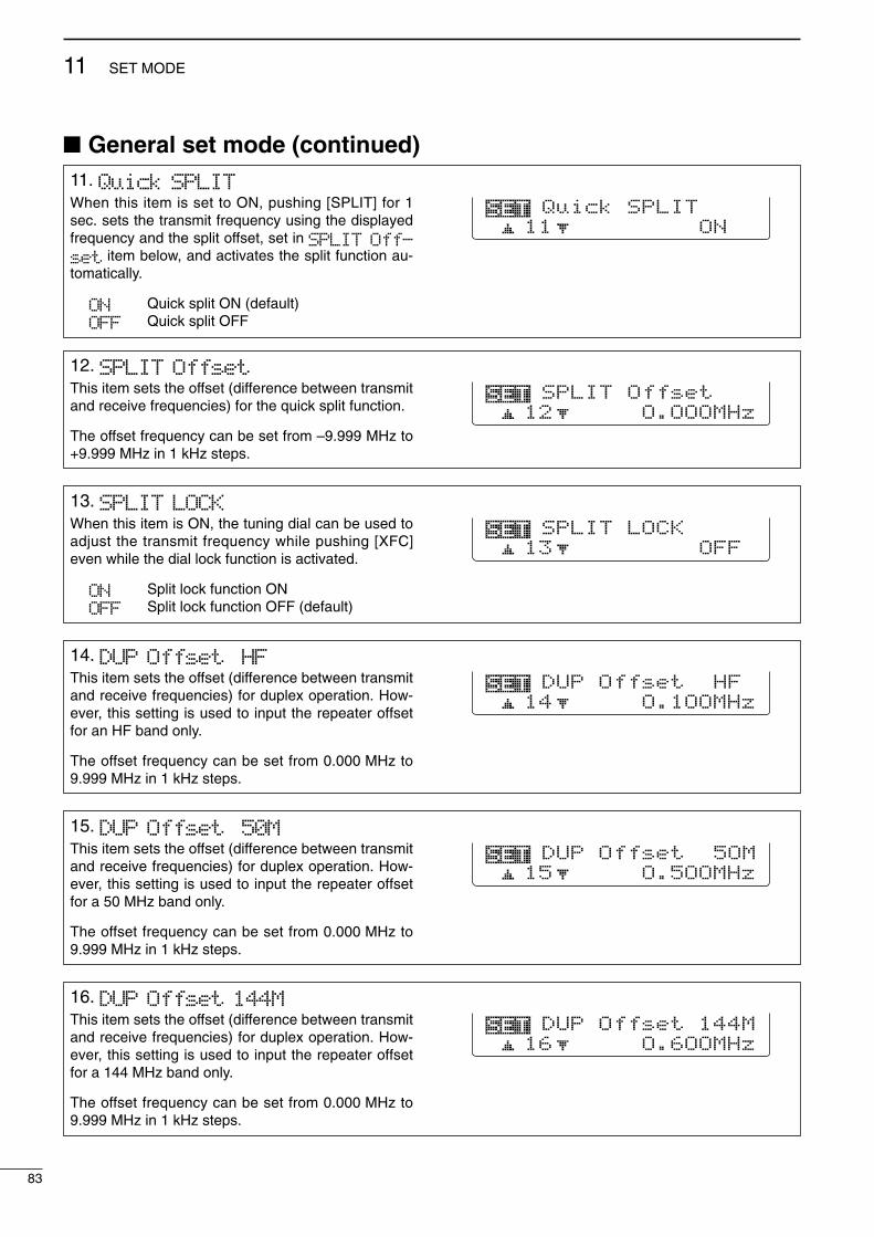
83
11 SET MODE
2001 NEW 2001 NEW
11. Quick SPLITWhen this item is set to ON, pushing [SPLIT] for 1sec. sets the transmit frequency using the displayedfrequency and the split offset, set in SPLIT Off-set item below, and activates the split function au-tomatically.
ON Quick split ON (default)OFF Quick split OFF
11 ONQuick SPLIT
12. SPLIT OffsetThis item sets the offset (difference between transmitand receive frequencies) for the quick split function.
The offset frequency can be set from –9.999 MHz to+9.999 MHz in 1 kHz steps.
12 O.OOOMHzSPLIT Offset
13. SPLIT LOCKWhen this item is ON, the tuning dial can be used toadjust the transmit frequency while pushing [XFC]even while the dial lock function is activated.
ON Split lock function ONOFF Split lock function OFF (default)
13 OFFSPLIT LOCK
14. DUP Offset HFThis item sets the offset (difference between transmitand receive frequencies) for duplex operation. How-ever, this setting is used to input the repeater offsetfor an HF band only.
The offset frequency can be set from 0.000 MHz to9.999 MHz in 1 kHz steps.
14 O.1OOMHzDUP Offset HF
15. DUP Offset 50MThis item sets the offset (difference between transmitand receive frequencies) for duplex operation. How-ever, this setting is used to input the repeater offsetfor a 50 MHz band only.
The offset frequency can be set from 0.000 MHz to9.999 MHz in 1 kHz steps.
15 O.5OOMHzDUP Offset 5OM
General set mode (continued)
16. DUP Offset 144MThis item sets the offset (difference between transmitand receive frequencies) for duplex operation. How-ever, this setting is used to input the repeater offsetfor a 144 MHz band only.
The offset frequency can be set from 0.000 MHz to9.999 MHz in 1 kHz steps.
16 O.6OOMHzDUP Offset 144M
IC-746PRO.qxd 02.4.2 11:31 Page 83

2001 NEW
84
11SET MODE
17. One Touch RptrThis item turns the one touch repeater function ON(DUP- or DUP+) and OFF.
When [F2 DUP] is pushed for 1 sec. in M1, the se-lected offset direction and the programmed duplexoffset frequency (depending on the operating fre-quency band) is set with the displayed frequency.
17 DUP-One Touch Rptr
18. Auto RepeaterThis item turns the auto repeater function to ON-1(auto duplex setting), ON-2 (auto duplex setting andactivating tone encoder) or OFF.
See p. 46 for details concerning the auto repeaterfunction.
18 ON-1Auto Repeater
19. Auto TuneThe internal antenna tuner has an automatic start ca-pability which starts tuning if the SWR is higher than1.5–3:1 in the HF bands.
When “OFF” is selected, the tuner remains OFF evenwhen the SWR is poor (1.5–3:1). When “ON” is se-lected, automatic tune starts even when the tuner isturned OFF.
19 OFFAuto Tune
20. PTT TuneTuning of the internal or external antenna tuner canbe started automatically at the moment the PTT ispushed after the operating frequency is changed(more than 1% from the last-tuned frequency).
2O OFFPTT Tune
21. 96OObps ModeThis item turn the 9600 bps data transmission capa-bility ON and OFF.
ON : For 9600 bps data transmission.OFF : For the regular audio (or slower data)
transmission only.
21 OFF96OObps Mode
General set mode (continued)
IC-746PRO.qxd 02.4.2 11:31 Page 84

85
11 SET MODE
2001 NEW 2001 NEW
22. [ANT] SwitchYou can set the antenna connector selection to auto-matic, manual or non-selection (when using 1 an-tenna only for the HF/50 MHz bands).
Auto : The antenna switch is activated andthe band memory memorizes the se-lected antenna. (default)
Manual: The antenna switch is activated andselects an antenna manually.
OFF : The antenna switch is not activatedand does not function. The [ANT1] con-nector is always selected in this case.
22 Auto[ANT] Switch
23. SPEECH LanguageWhen the optional UT-102 VOICE SYNTHESIZER UNIT isinstalled, you can select between English and Japan-ese as the language.
English : Announces in English (default)Japanese : Announces in Japanese
See p. 90 for unit installation.
23 EnglishSPEECH Language
24. SPEECH SpeedWhen the optional UT-102 VOICE SYNTHESIZER UNIT isinstalled, you can select between faster or slowersynthesizer output.
HIGH : Announces faster (default)LOW : Announces slower
See p. 90 for unit installation.
24 HIGHSPEECH Speed
25. SPEECH S-LevelWhen the optional UT-102 VOICE SYNTHESIZER UNIT isinstalled, you can have frequency, mode and signallevel announcement. Signal level announcement canbe deactivated if desired.
ON : Announces operating frequency, modeand receiving signal level. (default)
OFF : Announces operating frequency andmode only.
See p. 90 for unit installation.
25 ONSPEECH S-Level
26. Memory Pad ChThis item sets the number of memo pad channelsavailable. 5 or 10 memo pads can be set.
5 : 5 memo pads (default)10 : 10 memo pads
26 5Memory Pad Ch
General set mode (continued)
IC-746PRO.qxd 02.4.2 11:32 Page 85

86
11SET MODE
2001 NEW
27. DIAL Auto TSThis item sets the auto tuning step function. When ro-tating the tuning dial rapidly, the tuning step automat-ically changes several times as selected.
There are 2 type of auto tuning steps: HIGH (Fastest)and LOW (Faster).
HIGH : Auto tuning step is turned ON. Approx. 5 times fastest tuning stepduring rapid rotation (default)
LOW : Auto tuning step is turned ON. Approx. 2 times faster tuning step dur-ing rapid rotation
OFF : Auto tuning step is turned OFF.
27 HIGHDIAL Auto TS
28. MIC U/D SpeedThis item sets the rate at which frequencies arescanned when the microphone [UP]/[DN] switchesare pushed and held. High or low can be selected.
HIGH : High speed (default, 50 tuningsteps/sec.)
LOW : Low speed (25 tuning steps/sec.)
28 HIGHMIC U/D Speed
29. Quick RIT ClearThis item selects the RIT/∂TX frequency clearing in-struction with [PBTC].
ON : Clears the RIT/∂TX frequency when[PBTC] is pushed momentarily.
OFF : Clears the RIT/∂TX frequency when[PBTC] is pushed for 1 sec. (default)
29 OFFQuick RIT Clear
30. BW Popup (PBT)This item turns the PBT shifting value indication ONand OFF during [TWIN PBT] control operation. Whenset to ON, the shifting value is displayed above themulti-function switches.(default: ON)
3O ONBW Popup (PBT)
31. BW Popup (FIL)This item turns the IF filter width indication ON andOFF when selecting with [FILTER]. When set to ON,the filter width is displayed above the multi functionswitches.(default: ON)
31 ONBW Popup (FIL)
General set mode (continued)
IC-746PRO.qxd 02.4.2 11:32 Page 86

87
11 SET MODE
2001 NEW 2001 NEW
32. SSB/CW Synchronous TuningThis item selects the displayed frequency shift func-tion from ON and OFF.
When this function is activated, the receiving signalcan be kept in receive even when the operating modeis changed between SSB and CW.
ON : The displayed frequency shifts whenthe operating mode is changed be-tween SSB and CW.
OFF : The displayed frequency does not shift.(default)
The frequency shifting value may differ accordingto the CW pitch setting.
32 OFFSSB/CW Sync Tun
33. CW Normal SideSelects the carrier point of CW mode from LSB andUSB.
LSB : The carrier point is set to LSB side.(default)
USB : The carrier point is set to USB side.
33 LSBCW Normal Side
34. KEYER 1st MenuThis item selects the appearing menu when [F4 KEY]is pushed in M1 at first, from KEYER-Root andKEYER-SEND.
KEYER-Root : Selects memory keyermenu first (default)
KEYER-SEND : Selects keyer SEND menufirst
34 KEYER-RootKEYER 1st Menu
General set mode (continued)
35. External KeypadThis item sets the external keypad capability.
OFF : External keypad does not func-tion. (default)
KEYER SEND : Pushing one of external keypadswitches, transmits the desiredkeyer memory contents duringCW mode operation.
For your informationThe diagram as at right shows the equivalent circuit ofan external keypad and connects to pin 3 and pin 7of the [MIC] connector (p. 12)
To [MIC] connector pin e
To [MIC] connector pin u
1.5kΩ±5%
1.5kΩ±5%
2.2kΩ±5%
4.7kΩ±5%
S1(T1/M1)
S2(T2/M2)
S3(T3/M3)
S4(T4/M4)
USER EXTERNAL KEYPAD
35 OFFExternal Keypad
IC-746PRO.qxd 02.4.2 11:32 Page 87

88
11SET MODE
2001 NEW
38. CI-V TransceiveTransceive operation is possible with the IC-746PROconnected to other Icom HF transceivers or receivers.
ON : Transceive ON (default)OFF : Transceive OFF
When “ON” is selected, changing the frequency, op-erating mode, etc. on the IC-746PRO automaticallychanges those of connected transceivers (or re-ceivers) and vice versa.
38 ONCI-V Transceive
39. CI-V 731 ModeWhen connecting the IC-746PRO to the IC-735 fortransceive operation, you must change the operatingfrequency data length to 4 bytes.•This item must be set to “ON” only when operating thetransceiver with the IC-735.
ON : 4 bytes of frequency dataOFF : 5 bytes of frequency data (default)
39 OFFCI-V 731 Mode
General set mode (continued)
37. CI-V AddressTo distinguish equipment, each CI-V transceiver hasits own Icom standard address in hexadecimal code.The IC-746PRO’s address is 66h.
When 2 or more IC-746PRO’s are connected to anoptional CT-17 CI-V LEVEL CONVERTER, rotate the tun-ing dial to select a different address for each IC-746PRO in the range 01h to 7Fh.
37 66hCI-V Address
36. CI-V Baud RateThis item sets the data transfer rate. 300, 1200, 4800,9600, 19200 bps and “Auto” are available.
Auto : Auto baud rate (default)3OO : 300 bps12OO : 1200 bps48OO : 4800 bps96OO : 9600 bps192OO : 19200 bps
When “Auto” is selected, the baud rate is automati-cally set according to the connected controller or re-mote controller.
36 AutoCI-V Baud Rate
IC-746PRO.qxd 02.4.2 11:32 Page 88

89
11 SET MODE
2001 NEW 2001 NEW
Tone control set mode
DDEntering tone control set modeTone levels (bass and treble) for each transmit and re-ceive audio can be set for each phone mode indepen-dently.
•Set mode operationq Push [MENU] several times to select M2.w Push [F4 TCN] to select the tone control set mode.e Push [F1 ≤] or [F2 ≥] to select the desired item.r Push [SSB] or [AM/FM] to select the desired oper-
ating mode.t Set the desired condition using the tuning dial.
•Push [F3] for 1 sec. to select a default value.y Push [MENU] to exit the set mode.
DDTone control set mode items
[F1 ≤]
Tuning dial[MENU]
[F2 ≥] [F4 TCN]
1. TX BassThis item adjusts the bass level of the transmit audiotone from –5 dB to +5 dB in 1 dB steps.
TX Bass SSBO1
2. TX TrebleThis item adjusts the treble level of the transmit audiotone from –5 dB to +5 dB in 1 dB steps.
TX Treble SSBO2
3. RX BassThis item adjusts the bass level of the receive audiotone from –5 dB to +5 dB in 1 dB steps.
RX Bass SSBO3
4. RX TrebleThis item adjusts the treble level of the receive audiotone from –5 dB to +5 dB in 1 dB steps.
RX Treble SSBO4
IC-746PRO.qxd 02.4.2 11:32 Page 89

12
90
OPTION INSTALLATION
2001 NEW
Opening the transceiver’s caseFollow the case and cover opening procedures shownhere when you want to install an optional unit or adjustthe internal units, etc.
CAUTION: DISCONNECT the DC power cablefrom the transceiver before performing any work onthe transceiver. Otherwise, there is danger of elec-tric shock and/or equipment damage.
q Remove the 2 screws from the left side of the trans-ceiver to remove the carrying handle as shown atright.
w Remove the 6 screws from the top of the trans-ceiver and the 6 screws from the sides, then lift upthe top cover.
e Turn the transceiver upside down.r Remove 6 screws from the bottom of the trans-
ceiver, then lift up the bottom cover.
UT-102 VOICE SYNTHESIZER UNIT
The UT-102 announces the accessed readout’s fre-quency, mode, etc. (S-meter level can also be an-nounced— p. 85) in a clear, electronically-generatedvoice, in English (or Japanese).Push [LOCK/SPCH] for 1 sec. to announce the fre-
quency, etc.
q Remove the top and bottom covers as shownabove.
w Remove the protective paper attached to the bot-tom of the UT-102 to expose the adhesive strip.
e Plug UT-102 into J1920 on the MAIN unit as shownin the diagram at right.
r Adjust the trimmer, SPCH LVL: R1925 on the MAINunit, to set the speech level if desired. Refer to theillustration at right.
t Return the top and bottom covers to their originalpositions.
MAIN unit
UT-102
J1920R1925
IC-746PRO.qxd 02.4.2 11:32 Page 90

91
12 OPTION INSTALLATION
2001 NEW 2001 NEW
CR-338 HIGH STABILITY CRYSTAL UNIT
By installing the CR-338, the total frequency stabilityof the transceiver will be improved.
q Remove the bottom covers as shown on the previ-ous page.
w Remove the 4 screws from the shield cover of theRF unit, and disconnect P2 (CHASSIS) from J761(MAIN), then lift up the shield cover.
e Remove the 8 screws from the RF unit, disconnectJ1, J121 and J151, then remove the RF unit.
r Remove the supplied internal crystal and replacewith the CR-338.
t Return the RF unit, J1, J121 and J151 to their orig-inal positions.
y Connect a frequency counter to the J262, 2LO IN,then adjust the reference frequency to be64.00000 MHz with the L1901 on the RF unit.
u Return the J262, shield cover, P2 and bottom cov-ers to their original positions.
Shield cover
RF unit
J761 (MAIN unit)
P2(CHASSIS)
TUNER(antenna tuner)connector
Black belt
Blue belt
J151Blue
J1Black
J121Red
CR-338Supplied crystal
Red belt
RF unitSolderingpoints
Connect a frequency counter, then adjustthe frequency to be 64.00000 MHz.
RF unit
J2622LO IN
L1901
IC-746PRO.qxd 02.4.2 11:32 Page 91

2001 NEW
13
92
MAINTENANCES
CA
N
TroubleshootingThe following chart is designed to help you correctproblems which are not equipment malfunctions.
If you are unable to locate the cause of a problem orsolve it through the use of this chart, contact your near-est Icom Dealer or Service Center.
PROBLEM POSSIBLE CAUSE SOLUTION REF.
RE
CE
IVE
PO
WE
RT
RA
NS
MIT
Power does not come onwhen the [POWER] switchis pushed.
No sounds come out fromthe speaker.
Sensitivity is too low, andonly strong signals are au-dible.
Received audio is unclearor distorted.
The [ANT] switch does notfunction
Transmitting is impossible.
Output power is too low.
No contact possible withanother station.
Transmit signal is unclearor distorted.
Repeater cannot be ac-cessed.
Programmed scan doesnot stop.
Programmed scan doesnot start.
Memory scan does notstart
Select memory scan doesnot start
• Power cable is improperly connected.• Fuse is blown.
• Volume level is too low.
• The squelch is closed.
• The transceiver is in transmitting condition.
• The antenna is not connected properly.• The antenna for another band is selected.
• The antenna is not properly tuned.
• The attenuator is activated.
•Wrong operating mode is selected.•PBT function is activated.• Noise blanker is turned ON when receiving a
strong signal.•Preamp is activated.
• The noise reduction is activated and the [NR]control is too far clockwise.
•The antenna switch has not been activated.
•The operating frequency is not set to a hamband.
• [RF PWR] is set too far counterclockwise• [MIC GAIN] is set too far counterclockwise•The antenna for another band is selected.
•The antenna is not properly tuned.
•RIT or ∂TX function is activated.
•Split frequency and/or duplex function are acti-vated.
• [MIC GAIN] is set too far clockwise
• Split frequency or duplex function is not acti-vated.
• Programmed subaudible tone frequency iswrong.
•Squelch is open.• [RF/SQL] is assigned to RF gain control andsquelch is open.
•The same frequencies have been programmedin scan edge memory channels P1 and P2.
•2 or more memory channels have not beenprogrammed.
•2 or more memory channels have not beendesignated as select channels.
• Re-connect the DC power cable correctly.• Check for the cause, then replace the fuse with
the spare one.(Fuses are installed in the DC power cable andthe internal PA unit.)
• Rotate [AF] clockwise to obtain a suitable lis-tening level.
• Turn [RF/SQL] to 10 o’clock position to open thesquelch.
• Push [TRANSMIT] to receive or check theSEND line of an external unit, if desired.
• Re-connect to the antenna connector.• Select an antenna suitable for the operating fre-
quency.• Push [TUNER] for 1 sec. to manually tune the
antenna.• Push [P.AMP/ATT] for 1 sec. to select “ATT OFF.”
• Select a suitable operating mode.•Push [PBTC] for 1 sec. to reset the function• Push [NB] to turn the noise blanker OFF.
•Push [P.AMP/ATT] once or twice to turn thefunction OFF.
• Set the [NR] control for maximum readability.
•Set the antenna switch in set mode to “Auto” or“Manual.”
•Set the frequency to a ham band.
• Rotate [RF PWR] clockwise.• Set [MIC GAIN] to a suitable position.•Select an antenna suitable for the operating fre-quency.
•Push [TUNER] for 1 sec. to manually tune theantenna.
•Push [RIT] or [∂TX] to turn the function OFF.
•Push [SPLIT] and/or [F2 DUP] (in M1) to turnthe function OFF.
• Set [MIC GAIN] to a suitable position.
• Push [SPLIT] and/or [F2 DUP] (in M1) to turnthe function ON
• Reset the frequency using set mode.
•Set [RF/SQL] to the threshold point.•Reset [RF/SQL] control assignment and set it tothe threshold point.
•Program different frequencies in scan edgememory channel P1 and P2.
•Program more than 2 memory channels.
•Designate more than 2 memory channels as se-lect channels for the scan.
p. 16p. 93
p. 23
p. 24
p. 25
—p. 75
pgs. 76,77
p. 48
p. 23p. 52p. 51
p. 48
p. 53
p. 85
p. 19
p. 25p. 25p. 75
pgs. 76,77
pgs. 48,57
pgs. 44,59
p. 25
pgs. 44,59
p. 45
p. 24pgs. 24,
82
p. 66
p. 63
p. 72
IC-746PRO.qxd 02.4.2 11:32 Page 92

93
13 MAINTENANCE
2001 NEW 2001 NEW
Fuse replacementIf a fuse blows or the transceiver stops functioning, tryto find the source of the problem, and replace the dam-aged fuse with a new, rated fuse.
The IC-746PRO has 2 types of fuses installed fortransceiver protection.•DC power cable fuses ................................FGB 30 A•Circuitry fuse ................................................FGB 5 A
DDDC power cable fuse replacementRefer the figure illustrated at right for the DC powercable fuse replacement.
DDCircuitry fuse replacementThe 13.8 V DC from the DC power cable is applied toall units in the IC-746PRO, except for the power am-plifier, through the circuitry fuse. This fuse is installed inthe PA unit.
q Remove the top cover as shown on p. 90.w Remove the 11 screws from the PA shielding plate,
then remove the plate.
e Replace the circuitry fuse as shown in the diagramat right.
r Replace the PA shielding plate and top cover.
Tuning dial brake adjustmentThe tension of the tuning dial may be adjusted to suityour preference.
The brake adjustment screw is located on the rightside of the tuning dial. See the figure at right.
Turn the brake adjustment screw clockwise or counter-clockwise to obtain a comfortable tension level whileturning the dial continuously and evenly in one direction.
PROBLEM POSSIBLE CAUSE SOLUTION REF.
DIS
PL
AY The displayed frequency
does not change properly.• The dial lock function is activated.• A set mode screen is selected.
•The internal CPU has malfunctioned.
• Push [LOCK/SPCH] to turn the function OFF.• Push [MENU] several times to exit the set
mode.•Reset the CPU.
p. 53—
p. 94
30 A fuse
Fuse
CAUTION: DISCONNECT the DC power cablefrom the transceiver when changing a fuse.
Light
Heavy
IC-746PRO.qxd 02.4.2 11:32 Page 93

2001 NEW
Resetting the CPUWhen first applying power or when the function doesnot seem to be operating normally, reset the CPU asfollows:
q Make sure the transceiver power is OFF.w While pushing [M-CL] and [F-INP], push [POWER]
for 1 sec. to turn power ON.•The internal CPU is reset.•The transceiver displays its initial VFO frequency whenresetting is complete.
e Correct the set mode settings after resetting, if de-sired.
NOTE: Resetting CLEARS all programmed con-tents in memory channels and returns programmedvalues in set mode to default values.
Frequency calibration (approximate)
A very accurate frequency counter is required to cali-brate the frequency of the transceiver. However, arough check may be performed by receiving radio sta-tion WWV, or other standard frequency signals.
CAUTION: Your transceiver has been thoroughlyadjusted and checked at the factory before beingshipped. You should not calibrate frequencies, ex-cept for special reasons.
q Push [SSB] to select USB mode.w Push [PBTC] for 1 sec. to clear the PBT settings
and make sure that the RIT/∂TX function is not ac-tivated.
e Set the frequency to the standard frequency stationminus 1 kHz.•When receiving WWV (10.000.00 MHz) as a standardfrequency, set the operating frequency for 9.999.00 MHz.
•Other standard frequencies can also be used.r Push [MENU] several times to select M1 or M2, if
necessary.t Push [MENU] for 1 sec. to select the set mode
screen.y Push [F1 ≤] or [F2 ≥] several times to select the
CAL. Marker item.u Rotate the tuning dial clockwise to turn the calibra-
tion marker ON.•Side tone may be heard.
i Adjust [CAL] pot on the rear side of the transceiverfor a zero beat with the received standard signal.•Zero beat means that two signals are exactly the samefrequency, resulting in a single tone being emitted.
o Rotate the tuning dial counterclockwise to turn thecalibration marker OFF.
!0 Push [MENU] to exit set mode.
CAL. Marker5 ON
[SSB][MENU] [PBTC]
[RF/SQL] [AF] [P.AMP/ATT] [CLEAR][RIT]
[CAL]
• Calibration marker item
[POWER] [F-INP] [M-CL]
94
13MAINTENANCE
IC-746PRO.qxd 02.4.2 11:32 Page 94
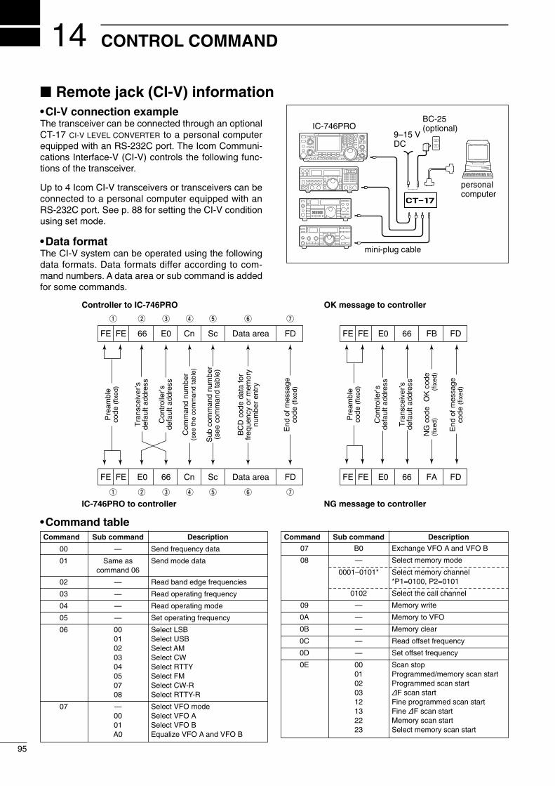
14
95
CONTROL COMMAND
2001 NEW
•CI-V connection exampleThe transceiver can be connected through an optionalCT-17 CI-V LEVEL CONVERTER to a personal computerequipped with an RS-232C port. The Icom Communi-cations Interface-V (CI-V) controls the following func-tions of the transceiver.
Up to 4 Icom CI-V transceivers or transceivers can beconnected to a personal computer equipped with anRS-232C port. See p. 88 for setting the CI-V conditionusing set mode.
•Data formatThe CI-V system can be operated using the followingdata formats. Data formats differ according to com-mand numbers. A data area or sub command is addedfor some commands.
Controller to IC-746PRO
FE FE 66 E0 Cn Sc Data area FD
Pre
ambl
eco
de (f
ixed
)
Tra
nsce
iver
’sde
faul
t add
ress
Con
trol
ler’s
defa
ult a
ddre
ss
Com
man
d nu
mbe
r(s
ee th
e co
mm
and
tabl
e)
Sub
com
man
d nu
mbe
r(s
ee c
omm
and
tabl
e)
BC
D c
ode
data
for
freq
uenc
y or
mem
ory
num
ber
entr
y
End
of m
essa
geco
de (f
ixed
)
OK message to controller
FE FE E0 66 FB FD
FE FE E0 66 FA FD
Pre
ambl
eco
de (f
ixed
)
Con
trol
ler’s
defa
ult a
ddre
ss
Tra
nsce
iver
’sde
faul
t add
ress
OK
cod
e(f
ixed
)
End
of m
essa
geco
de (f
ixed
)
NG message to controller
NG
cod
e(f
ixed
)
IC-746PRO to controller
q w e r t y u
FE FE E0 66 Cn Sc Data area FD
q w e r t y u
Remote jack (CI-V) information
9–15 VDC
personalcomputer
ct- 17
BC-25(optional)IC-746PRO
mini-plug cable
•Command tableCommand Sub command Description
00 — Send frequency data
01 Same as Send mode datacommand 06
02 — Read band edge frequencies
03 — Read operating frequency
04 — Read operating mode
05 — Set operating frequency
06 00 Select LSB01 Select USB02 Select AM03 Select CW04 Select RTTY05 Select FM07 Select CW-R08 Select RTTY-R
07 — Select VFO mode00 Select VFO A01 Select VFO BA0 Equalize VFO A and VFO B
Command Sub command Description
07 B0 Exchange VFO A and VFO B
08 — Select memory mode
0001–0101* Select memory channel*P1=0100, P2=0101
0102 Select the call channel
09 — Memory write
0A — Memory to VFO
0B — Memory clear
0C — Read offset frequency
0D — Set offset frequency
0E 00 Scan stop01 Programmed/memory scan start02 Programmed scan start03 ∂F scan start12 Fine programmed scan start13 Fine ∂F scan start22 Memory scan start23 Select memory scan start
IC-746PRO.qxd 02.4.2 11:32 Page 95

96
14CONTROL COMMAND
•Command table (continued)Command Sub command Description
0E A1–A7 Set ∂F scan span (A1=±5 kHz,A2=±10 kHz, A3=±20 kHz,A4=±50 kHz, A5=±100 kHz, A6=±500 kHz, A7=±1 MHz)
B0 Set as non-select channelB1 Set as select channelD0 Set scan resume OFFD3 Set scan resume ON
0F 00 Turn the split function OFF01 Turn the split function ON10 Select simplex operation11 Select –DUP operation12 Select +DUP operation
10 00 Select 10 Hz (1 Hz) tuning step01 Select 100 Hz tuning step02 Select 1 kHz tuning step03 Select 5 kHz tuning step04 Select 9 kHz tuning step05 Select 10 kHz tuning step06 Select 12.5 kHz tuning step07 Select 20 kHz tuning step08 Select 25 kHz tuning step
11 — Select/read attenuator (0=OFF,1=ON)
12 — Select/read antenna selection(0=ANT1, 1=ANT2)
13 00 Announce with voice synthesizer01 (00=all data; 01=frequency and 02 S-meter level; 02=receive mode)
14 01 + Level data [AF] level setting (0=max. CCW to255=max. CW)
02 + Level data [RF] level setting (0=max. CCW to255=11 o’clock)
03 + Level data [SQL] level setting (0=11 o’clock to255=max. CW)
06 + Level data [NR] level setting (0=min. to255=max.)
07 + Level data Inside [TWIN PBT] setting or IFshift setting (0=max. CCW,128=center, 255=max. CW)
08 + Level data Outside [TWIN PBT] setting (0=max. CCW, 128=center,255=max. CW)
09 + Level data [CW PITCH] setting (0=300 Hz,128=600 Hz, 255=900 Hz)
0A + Level data [RF PWR] setting (0=mini. to255=max.)
0B + Level data [MIC GAIN] setting (0=mini. to255=max.)
0C + Level data [KEY SPEED] setting (0=slow to255=fast)
0D + Level data [NOTCH] setting (0=low freq. to255=high freq.)
0E + Level data COMP Level Delay setting (0=0 to10=10)
0F + Level data Break-IN DELAY setting (20=2.0dto 130=13.0d)
15 01 Read squelch condition02 Read S-meter level11 Read RF power meter 12 Read SWR meter 13 Read ALC meter
16 02 Preamp (0=OFF; 1=preamp 1;2=preamp 2)
Command Sub command Description
16 12 AGC selection (0=OFF; 1=Slow;2=Mid; 3=Fast)
22 Noise blanker (0=OFF; 1=ON)40 Noise reduction (0=OFF; 1=ON)41 Auto notch (0=OFF; 1=ON)42 Repeater tone (0=OFF; 1=ON)43 Tone squelch (0=OFF; 1=ON)44 Speech compressor (0=OFF; 1=ON)45 Monitor (0=OFF; 1=ON)46 VOX function (0=OFF; 1=ON)47 Break-in (0=OFF; 1=semi break-
in; 2=full break-in)48 Manual notch (0=OFF; 1=ON)49 RTTY filter (0=OFF; 1=ON)4B DTCS (0=OFF; 1=ON)4C VSC (0=OFF; 1=ON)
19 00 Read the transceiver ID
1A 00 Send/read memory contents (seep. 97 for details)
01 Send/read band stacking registercontents (see p. 97 for details)
02 Send/read memory keyer con-tents (see p. 97 for details)
03 Send/read the selected filter width(0=50 Hz to 40/31=3600/2700 Hz)
04 Send/read the selected AGC timeconstant (0=OFF, 1=0.1/0.3 sec. to13=6.0/8.0 sec.)
0501 Send/read LCD contrast (0=0% to255=100%)
0502 Send/read LCD backlight (0=0% to255=100%)
0503 Send/read beep gain (0=min. to255=max.)
0504 Send/read beep gain limit (0=OFF,1=ON)
0505 Send/read calibration marker(0=OFF, 1=ON)
0506 Send/read confirmation beep(0=OFF, 1=ON)
0507 Send/read band edge beep(0=OFF, 1=ON)
0508 Send/read RF/SQL control set(0=Auto, 1=SQL, 2=RF+SQL)
0509 Send/read meter peak hold set(0=OFF, 1=ON)
0510 Send/read COMP meter set(0=OFF, 1=ON)
0511 Send/read quick split set (0=OFF,1=ON)
0512 Send/read split offset –9.999 to+9.999 MHz (see p. 98 for details)
0513 Send/read split lock set (0=OFF,1=ON)
0514 Send/read duplex offset 0.000 to9.999 MHz for HF (see p. 98 fordetails)
0515 Send/read duplex offset 0.000 to9.999 MHz for 50 MHz band (seep. 98 for details)
0516 Send/read duplex offset 0.000 to9.999 MHz for 144 MHz band(see p. 98 for details)
IC-746PRO.qxd 02.4.2 11:32 Page 96

97
14 CONTROL COMMAND
2001 NEW 2001 NEW
•Command table (continued)Command Sub command Description
1A 0548 Send/read FM TX Tone (Treble)level (0=–5 to 10=+5)
0549 Send/read FM RX Tone (Bass)level (0 =–5 to 10=+5)
0550 Send/read FM RX Tone (Treble)level (0=–5 to 10=+5)
0551 Send/read contact number style (0=Normal, 1=190→ANO,2=190→ANT, 3=90→NO,4=90→NT)
0552 Send/read count up trigger chan-nel (1=M1, 2=M2, 3=M3, 4=M4)
0553 Send/read present number(1–9999)
0554 Send/read CW side tone gain(0=min. to 255=max.)
0555 Send/read CW side tone gain limit(0=OFF, 1=ON)
0556 Send/read CW keyer repeat time(1=1 sec. to 60=60 sec.)
0557 Send/read CW keyer dot/dashratio (28=1:1:2.8 to 45=1:1:4.5)
0558 Send/read rise time (0=2 msec.,1=4 msec., 2=6 msec., 3=8 msec.)
0559 Send/read paddle polarity (0=Normal, 1=Reverse)
0560 Send/read keyer type (0=Straight,1=Bug-key, 2=ELEC-Key)
0561 Send/read mic. up/down keyer set(0=OFF, 1=ON)
0562 Send/read RTTY filter bandwidth (0=250 Hz, 1=300 Hz, 2=350 Hz,3=500 Hz, 4=1 kHz)
0563 Send/read twin peak filter (0=OFF,1=ON)
0564 Send/read RTTY mark frequency(0=1275 Hz, 1=1615 Hz,2=2125 Hz)
0565 Send/read RTTY shift width(0=170 Hz, 1=200 Hz, 2=425 Hz)
0566 Send/read RTTY keying polarity(0=Normal, 1=Reverse)
0567 Send/read RTTY decode USOS(0=OFF, 1=ON)
0568 Send/read RTTY decode new linecode (0=CR,LF,CR+LF, 1=CR+LF)
0569 Send/read number of RTTY de-coder line (0=2 lines, 1=3 lines)
0570 Send/read scan speed (0=Low,1=High)
0571 Send/read scan resume (0=OFF,1=ON)
0572 Send/read NB level (0=0% to255=100%)
0573 Send/read VOX gain (0=0% to255=100%)
0574 Send/read anti VOX gain (0=0% to255=100%)
0575 Send/read VOX delay (0=0.0 sec.to 20=2.0 sec.)
0576 Send/read Break-IN delay set(20=2.0d to 130=13.0d)
Command Sub command Description
1A 0517 Send/read one touch repeater set(0=DUP–, 1=DUP+)
0518 Send/read auto repeater set(0=OFF, 1=ON-1, 2=ON-2)
0519 Send/read tuner auto start set(0=OFF, 1=ON)
0520 Send/read PTT tune set (0=OFF,1=ON)
0521 Send/read 9600 bps mode set(0=OFF, 1=ON)
0522 Send/read antenna selection(0=OFF, 1=Manual, 2=Auto)
0523 Send/read speech language(0=English, 1=Japanese)
0524 Send/read speech speed (0=Slow,1=Fast)
0525 Send/read S-level speech (0=OFF,1=ON)
0526 Send/read memo pad numbers(0=5 ch, 1=10 ch)
0527 Send/read main dial auto TS(0=OFF, 1=Low, 2=High)
0528 Send/read mic. up/down speed(0=Low, 1=High)
0529 Send/read quick RIT/∂TX clearfunction (0=OFF, 1=ON)
0530 Send/read PBT shifting valuepopup set (0=OFF, 1=ON)
0531 Send/read IF filter width popupset (0=OFF, 1=ON)
0532 Send/read SSB/CW synchronoustuning function (0=OFF, 1=ON)
0533 Send/read CW normal side set(0=LSB, 1=USB)
0534 Send/read keyer 1st menu set(0=Keyer-root, 1=Keyer-send)
0535 Send/read external keypad set(0=OFF, 1=Keyer send)
0536 Send/read CI-V transceive set(0=OFF, 1=ON)
0537 Send/read CI-V 731 mode set(0=OFF, 1=ON)
0538 Send/read speech compressorlevel set (0=0 to 10=10)
0539 Send/read SSB TX Tone (Bass)level (0 =–5 to 10=+5)
0540 Send/read SSB TX Tone (Treble)level (0=–5 to 10=+5)
0541 Send/read SSB RX Tone (Bass)level (0 =–5 to 10=+5)
0542 Send/read SSB RX Tone (Treble)level (0=–5 to 10=+5)
0543 Send/read AM TX Tone (Bass)level (0 =–5 to 10=+5)
0544 Send/read AM TX Tone (Treble)level (0=–5 to 10=+5)
0545 Send/read AM RX Tone (Bass)level (0 =–5 to 10=+5)
0546 Send/read AM RX Tone (Treble)level (0=–5 to 10=+5)
0547 Send/read FM TX Tone (Bass)level (0 =–5 to 10=+5)
IC-746PRO.qxd 02.4.2 11:32 Page 97

98
14CONTROL COMMAND
2001 NEW
•Command table (continued)
DD To send/read memory contentsWhen sending or reading memory contents, additional codeas follows must be added to appoint the memory channel.Additional code: 0000–0102 (0100=P1, 0101=P2, 0102=Call)
DD Band stacking registerTo send or read the desired band stacking register ’s con-tents, combined code of the frequency band and registercodes as follows are used. For example, when sending/reading the oldest contents inthe 21 MHz band, the code “0703” is used.
•Frequency band code
•Register code
DD Codes for memory keyer contentsTo send or read the desired memory keyer contents, thechannel and character codes as follows are used.
• Channel code
• Character ’s code
DD Codes for memory name contentsTo send or read the desired memory name settings, the char-acter codes, instructed codes for memory keyer contents asabove, and follows are additionally used. • Character ’s code— Alphabetical characters
• Character ’s code— Symbols
Character ASCII code Character ASCII codea–z 61–7A — —
Code Frequency band Frequency range (unit: MHz)01 1.8 1.800000– 1.99999902 3.5 3.400000– 4.09999903 7 6.900000– 7.49999904 10 9.900000–10.49999905 14 13.900000–14.49999906 18 17.900000–18.49999907 21 20.900000–21.49999908 24 24.400000–25.09999909 28 28.000000–29.99999910 50 50.000000–54.00000011 144 144.000000–148.00000012 GENE Other than above
Code Registered number01 1 (latest)02 203 3 (oldest)
Character ASCII code Description0–9 30–39 NumeralsA–Z 41–5A Alphabetical characters
space 20 Word space / 2F Symbol? 3F Symbol, 2C Symbol. 2E Symbol^ 5E e.g., to send BT, enter ^4254 2A Inserts contact number (can be
used for 1 channel only)
Code Channel number01 M102 M203 M304 M4
Command Sub command Description
1A 0577 Send/read MONITOR level (0=0%to 255=100%)
06 Send/read DATA mode (0=OFF,1=ON)
07 Send/read SSB transmit band-width (0=WIDE, 1=MID, 2=NAR)
08 Send/read DSP filter shape(0= sharp, 1= soft)
1B 00 Set/read repeater tone frequency(see p. 98 for details)
01 Set/read TSQL tone frequency(see p. 98 for details)
02 Set/read DTCS code and polarity(see p. 98 for details)
1C 00 Set/read the transceiver’s condi-tion (0=Rx; 1=Tx)
01 Set/read antenna tuner condition (0=OFF, 1=ON, 2=Start tuning orwhile tuning)
Character ASCII code Character ASCII code! 21 # 23$ 24 % 25& 26 ¥ 5C? 3F ” 22’ 27 ` 60+ 2B – 2D: 3A ; 3B= 3D < 3C> 3E ( 28) 29 [ 5B] 5D 7B 7D | 7C_ 5F – 7E
IC-746PRO.qxd 02.4.2 11:32 Page 98

DD Split/Duplex frequency settingThe following data sequence is used when sending/readingthe split or duplex frequency setting.
DD Repeater tone/tone squelch frequency settingThe following data sequence is used when sending/readingthe DTCS code and polarity setting.
DD DTCS code and polarity settingThe following data sequence is used when sending/readingthe DTCS code and polarity setting.
Fix
ed d
igit:
0
1st d
igit:
0–7
2nd
digi
t: 0–
7
3rd
digi
t: 0–
7
Tra
nsm
it po
larit
y:
0= N
orm
al1=
Rev
erse
Rec
eive
pol
arity
: 0=
Nor
mal
1= R
ever
se
q
XX 0 X X
w e
X
100H
z di
git:
0–2
10 H
z di
git:
0–9
1 H
z di
git:
0–9
0.1
Hz
digi
t: 0–
9
Fix
ed d
igit:
0*
Fix
ed d
igit:
0*
q*
00 X X X
w e
X
*Not necessary when setting a frequency.
1 kH
z di
git:
0—9
100
Hz
digi
t: 0
(fix
ed)
100
kHz
digi
t: 0—
9
10 k
Hz
digi
t: 0—
9
10 M
Hz
digi
t: 0
(fix
ed)
1 M
Hz
digi
t: 0—
4
Dire
ctio
n:
00=
+ d
irect
ion
01=
— d
irect
ion
q
0X X X X XX
w e
0
r*
*No need to enter for duplex frequency setting.
99
14 CONTROL COMMAND
2001 NEWIC-746PRO.qxd 02.4.2 11:32 Page 99

15
100
SPECIFICATIONS
2001 NEW
•General•Frequency coverage : (Unit: MHz)Receive 0.030– 60.000000*
108.000– 174.000000*Transmit 1.800– 2.000000
3.500– 3.9999997.000– 7.300000
10.100– 10.15000014.000– 14.35000018.068– 18.16800021.000– 21.45000024.890– 24.99000028.000– 29.70000050.000– 54.000000
144.000– 148.000000*Some frequency ranges are not guaranteed.
•Mode : USB, LSB, CW, RTTY, AM, FM•No. of memory ch. : 102 (99 regular, 2 scan edges and 1
call)•Antenna connector : SO-239×3 (2 for HF/50 MHz and 1
for 144 MHz; 50 Ω)•Operating temp. range : –10˚C to +60˚C ; +14˚F to +140˚F•Frequency stability : Less than ±7 ppm from 1 min. to
60 min. after power ON. Afterthat, rate of stability is less than±1 ppm/hr. at 25˚C (+77˚F).Temperature fluctuations 0˚C to+50˚C (+20˚F to +122˚F) less than±5 ppm.
•Frequency resolution : 1 Hz•Power supply : 13.8 V DC ±15% (negative ground)•Power consumption :
Transmit Max. power 23.0 AReceive Standby 2.2 A
Max. audio 3.0 A•Dimensions : 287(W)×120(H)×316.5(D) mm
(projections not incl.) 135⁄16(W)×423⁄32(H)×1215⁄32(D) in•Weight (approx.) : 9.0 kg; 19 lb 13 oz•ACC 1 connector : 8-pin DIN connector•ACC 2 connector : 7-pin DIN connector•DATA connector : Mini DIN 6-pin •CI-V connector : 2-conductor 3.5 (d) mm (1⁄8″)
•Transmitter•Output power (continuously adjustable):
SSB/CW/RTTY/FM Less than 5 to 100 WAM Less than 5 to 40 W
•Modulation system :SSB PSN modulationAM Low power modulationFM Phase modulation
•Spurious emission : 50 dB (HF bands)60 dB (50/144 MHz)
•Carrier suppression : 40 dB•Unwanted sideband : 55dBsuppression
•∂TX variable range : ±9.99 kHz•Mic. connector : 8-pin connector (600 Ω)•ELEC-KEY connector : 3-conductor 6.35(d) mm (1⁄4″)•KEY connector : 3-conductor 6.35(d) mm (1⁄4″)•SEND connector : Phono (RCA)•ALC connector : Phono (RCA)
•Receiver•Receive system : Triple conversion
superheterodyne system• Intermediate frequencies:
1st 64.455 MHz2nd 455 kHz3rd 36 kHz
•Sensitivity (typical) :SSB, CW, RTTY 0.16 µV*1 (1.80–29.99 MHz)(10 dB S/N) 0.13 µV*2 (50 MHz)
0.11 µV*3 (144 MHz)AM (10 dB S/N) 13 µV (0.5–1.799 MHz)
2 µV*1 (1.80–29.99 MHz)1 µV (50*2/144*3 MHz)
FM (12 dB SINAD) 0.5 µV*1 (28.0–29.99 MHz)0.25 µV*2 (50 MHz)0.18 µV*3 (144 MHz)
*1Pre-amp 1 is ON, *2Pre-amp 2 is ON, *3Pre-amp is ON•Squelch sensitivity (Pre-amp: OFF):
SSB, CW, RTTY Less than 5.6 µVFM Less than 1.0 µV
•Selectivity :SSB (BW: 2.4 kHz) More than 2.4 kHz/–6 dB
Less than 3.6 kHz/–60 dBCW (BW: 500 Hz) More than 500 Hz/–6 dB
Less than 700 Hz/–60 dBRTTY (BW: 350 Hz) More than 360 Hz/–6 dB
Less than 650 Hz/–60 dBAM (BW: 6 kHz) More than 6.0 kHz/–6 dB
Less than 15.0 kHz/–60 dBFM (BW: 15 kHz) More than 12.0 kHz/–6 dB
Less than 20.0 kHz/–60 dB•Spurious and image rejection ratio:
HF/50 MHz More than 70 dB (except IF throughon 50 MHz band)
144 MHz More than 60 dB•AF output power : More than 2.0 W at 10% distortion
(at 13.8 V DC) with an 8 Ω load•RIT variable range : ±9.99 kHz•PHONES connector : 3-conductor 6.35 (d) mm (1⁄4″)•Ext. SP connector : 2-conductor 3.5 (d) mm (1⁄8″)/8Ω
•Antenna tuner•Matching impedance range:
HF bands 16.7 to 150 Ω unbalanced(Less than VSWR 3:1)
50 MHz band 20 to 125 Ω unbalanced(Less than VSWR 2.5:1)
•Minimum operating input power: 8 W (HF bands)
15 W (50 MHz band)•Tuning accuracy : VSWR 1.5:1 or less• Insertion loss : Less than 1.0 dB (after tuning)
All stated specifications are typical and subject to change without no-tice or obligation.
IC-746PRO.qxd 02.4.2 11:32 Page 100

16
101
OPTIONS
2001 NEW
IC-PW1 HF/50 MHz ALL BAND 1 kW LINEAR AMPLIFIER
Full-duty 1 kW linear amplifier including an automatic antenna tuner. Hasautomatic tuning and band selection capability. Full break-in (QSK) oper-ation is possible. The amplifier/power supply unit and the remote controlunit are separated.
AH-4 HF/50 MHz AUTOMATICANTENNA TUNER
Specially designed to tune a longwire antenna for portable or mobileHF operation. The PTT tuner startfunction provides simple operation.• Input power rating: 120 W
AH-2b ANTENNA ELEMENT
A 2.5 m long an-tenna element formobile operationwith the AH-4.•Frequency coverage:7–54 MHz bandswith the AH-4
SM-20 DESKTOP MICROPHONE
Unidirectional, electret microphonefor base station operation. Includes[UP]/[DOWN] switches and a lowcut function.
SP-21 EXTERNAL SPEAKER
Designed for base station opera-tion.• Input impedance: 8 Ω•Max. input power: 5 W
CT-17 CI-V LEVEL CONVERTER
For remote transceiver controlusing a personal computer. Youcan change frequencies, operatingmode, memory channels, etc.
UT-102 VOICE SYNTHESIZER UNITAnnounces the receive frequency, modeand S-meter level in a clear, electroni-cally-generated voice, in English (orJapanese).
SP-20 EXTERNAL SPEAKER4 audio filters; headphone jack; can con-nect to 2 transceivers.• Input impedance: 8 Ω•Max. input power: 5 W
CR-338 HIGH STABILITY CRYSTALUNIT
Contains a temperature-compensatingoven heater and crystal unit for improvedfrequency stability.•Frequency stability: ±0.5 ppm
HM-36 HAND MICROPHONEHand microphone equipped with[UP]/[DOWN] switches.
PS-125 DC POWER SUPPLY
Light weight switching regulatorsystem power supply.•Output voltage: 13.8 V DC•Max. current drain: 25 A
IC-746PRO.qxd 02.4.2 11:32 Page 101

2001 NEWIC-746PRO.qxd 02.4.2 11:32 Page 102

1-1-32 Kamiminami, Hirano-ku, Osaka 547-0003 Japan
A-6085H-1US-wPrinted in Japan© 2001, 2002 Icom Inc.
2001 NEWIC-746PRO.qxd 02.4.2 11:32 Page Z