all in 1: laser deposition welding and milling additive ... · lasertec all in 1: laser deposition...
TRANSCRIPT

LASERTEC
www.dmgmori.com
ALL IN 1: Laser Deposition Welding and Milling
Additive Manufacturing in Milling Quality
LASERTEC 65 3D
Additive Manufacturing
Laser Deposition Welding and Milling
LASERTEC Integration in DMG MORI Machines
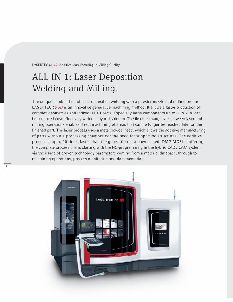
The unique combination of laser deposition welding with a powder nozzle and milling on the LASERTEC 65 3D is an innovative generative machining method. It allows a faster production of complex geometries and individual 3D-parts. Especially large components up to Ø 19.7 in. can be produced cost-effectively with this hybrid solution. The flexible changeover between laser and milling operations enables direct machining of areas that can no longer be reached later on the finished part. The laser process uses a metal powder feed, which allows the additive manufacturing of parts without a processing chamber nor the need for supporting structures. The additive process is up to 10 times faster than the generation in a powder bed. DMG MORI is offering the complete process chain, starting with the NC-programming in the hybrid CAD / CAM system, via the usage of proven technology parameters coming from a material database, through to machining operations, process monitoring and documentation.
LASERTEC 65 3D: Additive Manufacturing in Milling Quality
ALL IN 1: Laser Deposition Welding and Milling.
02

LASERTEC 65 3D
Applications.
The video of the Lasertec 65 3D:If your mobile phone is equipped with a QR code recognition software, then this link will take you to the video. Current brochures can be found under www.dmgmori.com
production repair coatings
#
aerospaceTurbine Casing
aerospaceBlisk
oil & gasDrill Bit
engineeringNozzle
energyPelton Wheel
engineeringBearing Block
vacuum technologyCooling Tube
mould makingInjection Mould
plant equipmentDrive Shaft
mold makingCooling Element
energyImpeller
vacuum technologyFlange
LASERTEC 65 3D
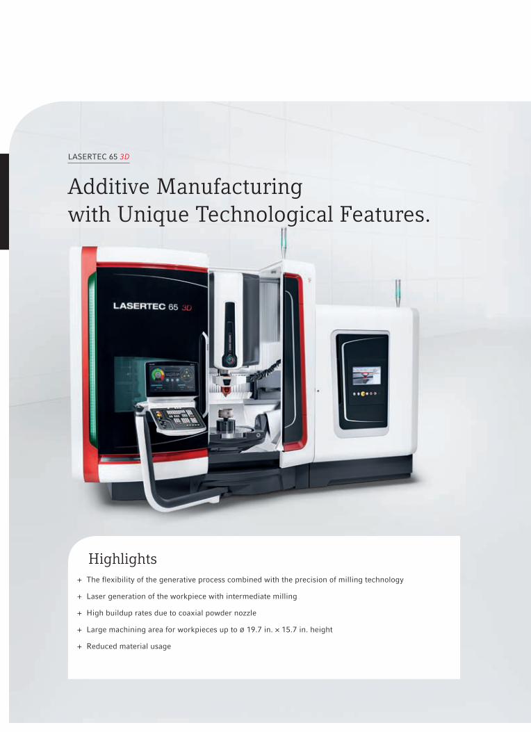
Additive Manufacturing with Unique Technological Features.
Highlights + The flexibility of the generative process combined with the precision of milling technology
+ Laser generation of the workpiece with intermediate milling
+ High buildup rates due to coaxial powder nozzle
+ Large machining area for workpieces up to Ø 19.7 in. × 15.7 in. height
+ Reduced material usage

MaterialsTried and tested materials:
+ Stainless Steel
+ Nickel-Based Alloys (Inconel 625, 718)
+ Tungsten Carbide Matrix Materials
+ Bronze and Brass Alloys
+ Chrome-Cobalt-Molybdenum Alloys
+ Stellite
+ Tool Steel (weldable)
Powder
Processing Direction
Laser Beam
Shielding / Carrier Gas
Dilution Zone
Workpiece
Deposited Material
Melt Pool
Working PrincipleUsing a coaxial nozzle, the metal powder is welded to the base material in layers (non-porous and crack free melting). Thereby the metal powder is joined with the surface in a high strength bonding. The coaxial nozzle shielding gas protects against oxidation during the buildup process. After cooling, the metal layers can be machined mechanically.
Basics Laser Deposition Welding.
MetallurgyContinuous process development in consideration of the following material characteristics:
+ Inspection of the powder material
+ Density measurement, structural analysis
+ Mechanical tests (tension, stress, bending)
+ Measurement: Surface quality, hardness, corrosion
+ 99.8% achievement of the casting density (e. g. Stainless Steel 316L / 1.4404)
Characteristics316L / 1.4404
Conventional Material
Requirements
Laser Welding
Results
Elastic Limit [Rp0,2] Mpa ≥ 200 229.5
Tensile Strength [Rm] Mpa 500 – 700 506
Elongation [A] % ≥ 40 53.05
Impact Test [KV2] J ≥ 100 126 – 132
Hardness [H] HV5 ≤ 230 160
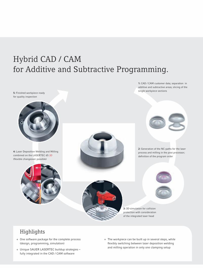
Hybrid CAD / CAM for Additive and Subtractive Programming.
Highlights + One software package for the complete process
(design, programming, simulation)
+ Unique SAUER LASERTEC buildup strategies – fully integrated in the CAD / CAM software
+ The workpiece can be built up in several steps, while flexibly switching between laser deposition welding and milling operation in only one clamping setup
1: CAD / CAM customer data; separation in
additive and subtractive areas; slicing of the
single workpiece sections
2: Generation of the NC-paths for the laser
process and milling in the post processor;
definition of the program order
3: 3D-simulation for collision
protection with consideration
of the integrated laser head
4: Laser Deposition Welding and Milling
combined on the LASERTEC 65 3D
(flexible changeover possible)
5: Finished workpiece ready
for quality inspection

Complete Generation of 3D-Parts Application Examples.
3: 90° swivel: Milling of the planesurface and the outer contour
3: Milling
5: Manufacturing of the 12 connectors
5: Building of the cylinder vanes
4: Continuation of the cylindergeneration with conical funnel
4: Finish machining of the cylinder
6: Finishing of the inner and outer contour
6: Finish milling of the vanes
1: Building a cylinder 2: Completion of the conical taper1: Basic setup of the cylinder 2: 90° swivel: Generation of the flange
Fan WheelMaterial: Stainless steelLaser Deposition Welding: 312 min.Milling: 240 min.Dimensions: Ø 6.3 in. × 6.3 in.
Turbine CasingMaterial: Stainless steelLaser Deposition Welding: 230 min.Milling: 76 min.Dimensions: Ø 7.1 in. × 5.9 in.
Laser Deposition Welding Laser Deposition WeldingMilling Milling
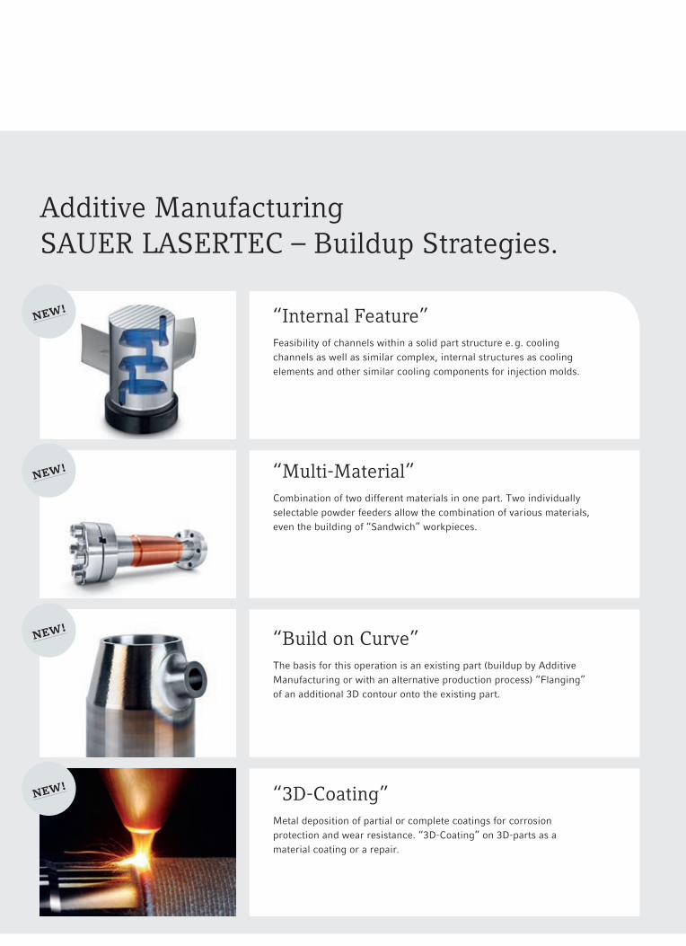
Additive Manufacturing SAUER LASERTEC – Buildup Strategies.
“Internal Feature”Feasibility of channels within a solid part structure e. g. cooling channels as well as similar complex, internal structures as cooling elements and other similar cooling components for injection molds.
“Multi-Material”Combination of two different materials in one part. Two individually selectable powder feeders allow the combination of various materials, even the building of “Sandwich” workpieces.
“Build on Curve”The basis for this operation is an existing part (buildup by Additive Manufacturing or with an alternative production process) “Flanging” of an additional 3D contour onto the existing part.
“3D-Coating”Metal deposition of partial or complete coatings for corrosion protection and wear resistance. “3D-Coating” on 3D-parts as a material coating or a repair.
new!
new!
new!
new!
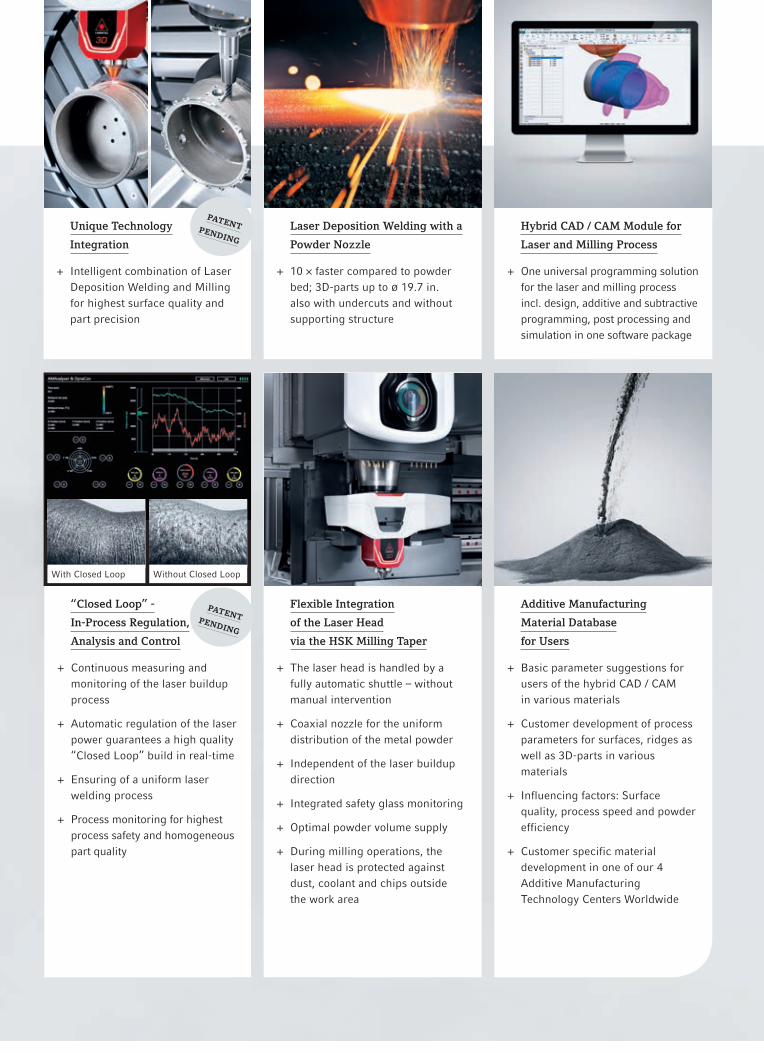
Laser Deposition Welding with a
Powder Nozzle
+ 10 × faster compared to powder bed; 3D-parts up to Ø 19.7 in. also with undercuts and without supporting structure
Hybrid CAD / CAM Module for
Laser and Milling Process
+ One universal programming solution for the laser and milling process incl. design, additive and subtractive programming, post processing and simulation in one software package
“Closed Loop” -
In-Process Regulation,
Analysis and Control
+ Continuous measuring and monitoring of the laser buildup process
+ Automatic regulation of the laser power guarantees a high quality “Closed Loop” build in real-time
+ Ensuring of a uniform laser welding process
+ Process monitoring for highest process safety and homogeneous part quality
Flexible Integration
of the Laser Head
via the HSK Milling Taper
+ The laser head is handled by a fully automatic shuttle – without manual intervention
+ Coaxial nozzle for the uniform distribution of the metal powder
+ Independent of the laser buildup direction
+ Integrated safety glass monitoring
+ Optimal powder volume supply
+ During milling operations, the laser head is protected against dust, coolant and chips outside the work area
With Closed Loop Without Closed Loop
patentpending
Unique Technology
Integration
+ Intelligent combination of Laser Deposition Welding and Milling for highest surface quality and part precision
patentpending
Additive Manufacturing
Material Database
for Users
+ Basic parameter suggestions for users of the hybrid CAD / CAM in various materials
+ Customer development of process parameters for surfaces, ridges as well as 3D-parts in various materials
+ Influencing factors: Surface quality, process speed and powder efficiency
+ Customer specific material development in one of our 4 Additive Manufacturing Technology Centers Worldwide
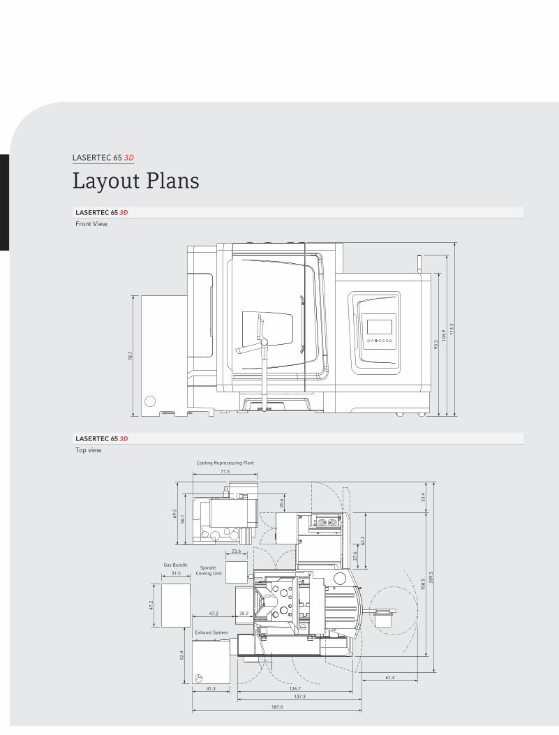
LASERTEC 65 3D
Layout PlansLASERTEC 65 3D
Front View
LASERTEC 65 3D
Top view
71.5
Cooling Reprocessing Plant
Spindle Cooling Unit
Gas Bundle
Exhaust System
126.7
61.4
137.3
41.3
47.2
31.5
23.6
20.2
187.0
209.
5
158.
5
62.4
47.2
56.169
.2
20.6 33
.4
62.2
27.6
78.7
93.3 10
4.9 113.
3
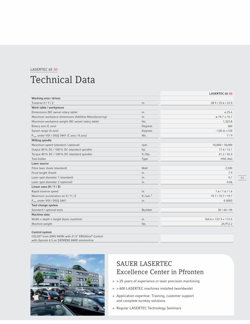
LASERTEC 65 3D
Technical DataLASERTEC 65 3D
Working area / drives
Traverse X / Y / Z in. 28.9 / 25.6 / 22.0
Work table / workpieces
Dimensions (NC swivel rotary table) in. ø 25.6
Maximum workpiece dimensions (Additive Manufacturing) in. ø 19.7 x 15.7
Maximum workpiece weight (NC swivel rotary table) lbs. 1,322.8
Rotary axis (C axis) Degrees 360
Swivel range (A axis) Degrees –120 to +120
Pmax under VDI / DGQ 3441 (C axis / A axis) Ws. 7 / 9
Milling spindle
Maximum speed (standard / optional) rpm. 10,000 / 18,000
Output 40 % DC / 100 % DC (standard spindle) hp. 17.4 / 12.1
Torque 40 % DC / 100 % DC (standard spindle) ft. / lbs. 61.2 / 42.0
Tool holder Type HSK-A63
Laser source
Fibre laser diode (standard) Watt 2,500
Focal length (fixed) in. 7.9
Laser spot diameter 1 (standard) in. 0.1
Laser spot diameter 2 (optional) in. 0.06
Linear axes (X / Y / Z)
Rapid traverse speed in. 1.6 / 1.6 / 1.6
Maximum acceleration on X / Y / Z ft. / sec.² 19.7 / 19.7 / 19.7
Pmax under VDI / DGQ 3441 in. 0.0003
Tool change system
Standard / optional tools Number 30 / 60 / 90
Machine data
Width × depth × height (basic machine) in. 164.6 × 137.3 × 113.5
Machine weight lbs. 24,912.2
Control systemCELOS® from DMG MORI with 21.5" ERGOline® Control with Operate 4.5 on SIEMENS 840D solutionline
11
SAUER LASERTEC Excellence Center in Pfronten
+ > 25 years of experience in laser precision machining
+ > 600 LASERTEC machines installed (worldwide)
+ Application expertise: Training, customer support and complete turnkey solutions
+ Regular LASERTEC Technology Seminars
MO
NTFO
RT
ADVERTIS
ING
PR
O. D
6685
/081
5US_
D68
07/0
816A
D18
Su
bjec
t to
mod
ifica
tion.
T
echn
ical
upd
ate
righ
ts r
eser
ved.
The
mac
hine
s de
pict
ed h
ere
may
incl
ude
som
e op
tions
, equ
ipm
ent a
nd C
NC
alte
rnat
ives
.
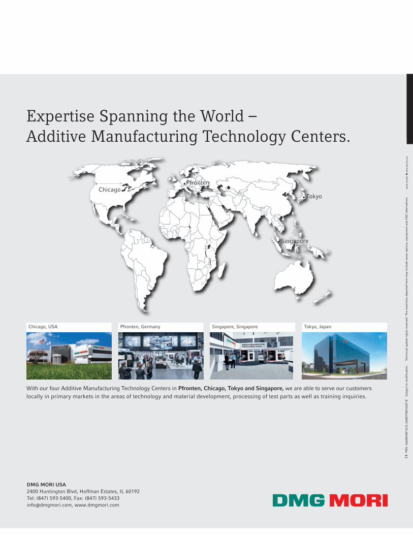
Expertise Spanning the World –Additive Manufacturing Technology Centers.
With our four Additive Manufacturing Technology Centers in Pfronten, Chicago, Tokyo and Singapore, we are able to serve our customers locally in primary markets in the areas of technology and material development, processing of test parts as well as training inquiries.
Chicago, USA Pfronten, Germany Singapore, Singapore Tokyo, Japan
ChicagoPfronten
Tokyo
Singapore
DMG MORI USA2400 Huntington Blvd, Hoffman Estates, IL 60192Tel: (847) 593-5400, Fax: (847) [email protected], www.dmgmori.com