additive manufacturing - interempresas · + programming the milling process with nx cam +...
TRANSCRIPT

LASERTEC
www.dmgmori.com
ALL IN 1: Laser Deposition Welding & Milling
Additive Manufacturingin Milling quality
LASERTEC 65 3D
Additive Manufacturing
Laser Deposition Welding & Milling
LASERTEC integration in DMG MORI machines
FLY
_D63
13_0
714U
K
S
ubje
ct t
o m
odif
icat
ion.
Tec
hnic
al u
pdat
e ri
ghts
res
erve
d. T
he m
achi
nes
depi
cted
her
e m
ay in
clud
e so
me
opti
ons,
equ
ipm
ent
and
CN
C a
lter
nati
ves.
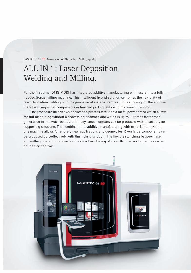
For the first time, DMG MORI has integrated additive manufacturing with lasers into a fully fledged 5-axis milling machine. This intelligent hybrid solution combines the flexibility of laser deposition welding with the precision of material removal, thus allowing for the additive manufacturing of full components in finished parts quality with maximum precision.
The procedure involves an application process featuring a metal powder feed which allows for full machining without a processing chamber and which is up to 10 times faster than generation in a powder bed. Additionally, steep contours can be produced with absolutely no supporting structure. The combination of additive manufacturing with material removal on one machine allows for entirely new applications and geometries. Even large components can be produced cost-effectively with this hybrid solution. The flexible switching between laser and milling operations allows for the direct machining of areas that can no longer be reached on the finished part.
LASERTEC 65 3D: Generation of 3D-parts in Milling quality
ALL IN 1: Laser DepositionWelding and Milling.

1
23
4
Machine features
1 Laser deposition welding with 2 kW laser diode with powder feed
2 Flexible integration of the laser head via the HSK-A63 interface: Combination of laser deposition welding and milling
3 The laser head is handled by a fully automatic shuttle
4 Integrated NC swivel rotary table for 5-axis simultaneous machining
Highlights LASERTEC 65 3D
+ Fully fledged 5-axis milling machine in the consistently stable monoBLOCK® design with a set-up area* of less than 12 m²
+ Fully automatic switching between laser and milling operations with shuttle handling via the HSK interface
+ Large working room for workpieces up to ø 500 mm, 350 mm height and max. 600 kg
+ Ergonomics: 1,430 mm door opening for the best accessibility from in front and above
+ Component design and programming with SIEMENS NX software
+ Monitoring of the application process and online laser output regulation by the integrated optical process monitor
+ CELOS from DMG MORI with 21.5" ERGOline® Control with Operate 4.5 on SIEMENS 840D solutionline
* Layout of the machine with no aggregates
MILLING
LASER DEPOSITION WELDING
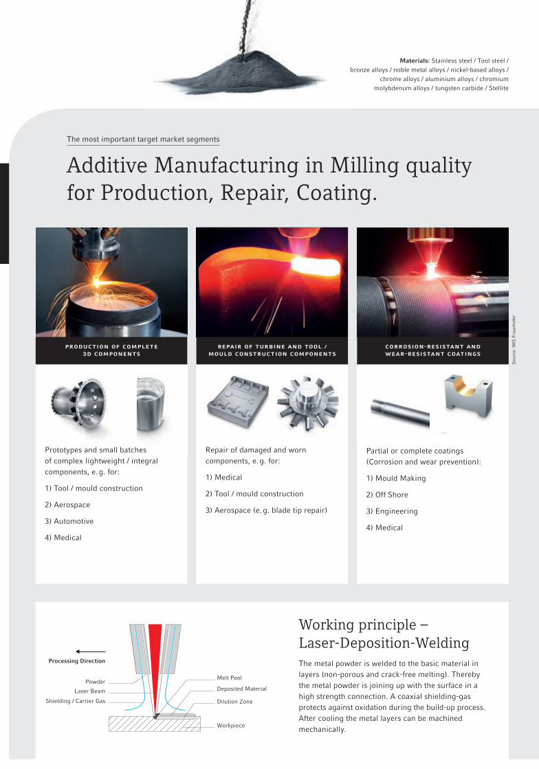
Working principle – Laser-Deposition-Welding The metal powder is welded to the basic material in layers (non-porous and crack-free melting). Thereby the metal powder is joining up with the surface in a high strength connection. A coaxial shielding-gas protects against oxidation during the build-up process. After cooling the metal layers can be machined mechanically.
The most important target market segments
Additive Manufacturing in Milling qualityfor Production, Repair, Coating.
Prototypes and small batches of complex lightweight / integral components, e. g. for:
1) Tool / mould construction
2) Aerospace
3) Automotive
4) Medical
Repair of damaged and worn components, e. g. for:
1) Medical
2) Tool / mould construction
3) Aerospace (e. g. blade tip repair)
Partial or complete coatings (Corrosion and wear prevention):
1) Mould Making
2) Off Shore
3) Engineering
4) Medical
Sou
rce:
IW
S F
raun
hofe
r
Materials: Stainless steel / Tool steel / bronze alloys / noble metal alloys / nickel-based alloys /
chrome alloys / aluminium alloys / chromium molybdenum alloys / tungsten carbide / Stellite
production of complete 3d components
repair of turbine and tool / mould construction components
corrosion-resistant and wear-resistant coatings
Powder
Processing Direction
Laser Beam
Shielding / Carrier Gas Dilution Zone
Workpiece
Deposited Material
Melt Pool
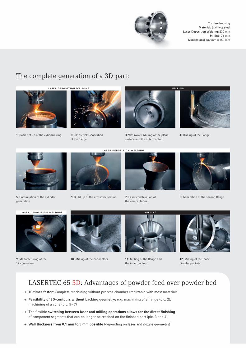
LASERTEC 65 3D: Advantages of powder feed over powder bed + 10 times faster; Complete machining without process-chamber (realizable with most materials)
+ Feasibility of 3D-contours without backing geometry: e. g. machining of a flange (pic. 2), machining of a cone (pic. 5 – 7)
+ The flexible switching between laser and milling operations allows for the direct finishing of component segments that can no longer be reached on the finished part (pic. 3 and 4)
+ Wall thickness from 0.1 mm to 5 mm possible (depending on laser and nozzle geometry)
The complete generation of a 3D-part:
Turbine housingMaterial: Stainless steel
Laser Deposition Welding: 230 min Milling: 76 min
Dimensions: 180 mm × 150 mm
1: Basic set-up of the cylindric ring
5: Continuation of the cylinder generation
9: Manufacturing of the 12 connectors
2: 90° swivel: Generation of the flange
6: Build-up of the crossover section
10: Milling of the connectors
3: 90° swivel: Milling of the plane surface and the outer contour
7: Laser construction of the conical funnel
11: Milling of the flange and the inner contour
4: Drilling of the flange
8: Generation of the second flange
12: Milling of the inner circular pockets
LASER DEpOSITIOn WELDInG
LASER DEpOSITIOn WELDInG
LASER DEpOSITIOn WELDInG
Milling
Milling

Highly stable, highly compact monoBLOCK® design with lateral laser head handling
Programming and machining
+ Entire components can be designed with the SIEMENS NX CAD module
+ Programming the milling process with NX CAM
+ Integration of a SAUER module into the NX software for additive manufacturing
+ The integrated optical process monitor monitors the application process and regulates the laser output online
+ The workpiece can be build-up in several steps. Intermediate milling operations are always possible.
+ It is even possible to produce full, large components
+ 3D-geometries with undercuts realizable
Laser head switching
+ The laser head is moved laterally into the working area by an automatic shuttle handling system
+ The spindle travels to the predefined change position
+ The laser head is automatically held in place and integrated by the HSK-A63 interface on the spindle
+ After the laser head has been adjusted, the shuttle returns to the change position in the working area
+ During milling operations, the laser head is located outside of the working area in order to protect it against coolant and chips
LASERTEC 65 3D
Front view Top view
2,00
0
2,37
0
2,66
4
2,87
7
1,816
3,218 1,560
3,4871,050
1,200
800
600
512
4,749
5,32
1
4,02
5
1,58
5
1,20
0
1,42
4
1,75
7 523 84
8
1,58
0
700
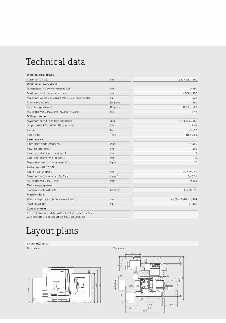
Technical data
Layout plans
Working area / drives
Traverse X / Y / Z mm 735 / 650 / 560
Work table / workpieces
Dimensions (NC swivel rotary table) mm ø 650
Maximum workpiece dimensions mm ø 500 x 350
Maximum workpiece weight (NC swivel rotary table) kg 600
Rotary axis (C axis) Degrees 360
Swivel range (A axis) Degrees –120 to +120
Pmax under VDI / DGQ 3441 (C axis / A axis) Ws 7 / 9
Milling spindle
Maximum speed (standard / optional) rpm 10,000 / 14,000
Output 40 % ED / 100 % ED (standard) kW 13 / 9
Torque Nm 83 / 57
Tool holder Type HSK-A63
Laser source
Fibre laser diode (standard) Watt 2,000
Focal length (fixed) mm 200
Laser spot diameter 1 (standard) mm 3
Laser spot diameter 2 (optional) mm 1.6
Deposition rate (varies by material) kg / h 1.0
Linear axes (X / Y / Z)
Rapid traverse speed mm 40 / 40 / 40
Maximum acceleration on X / Y / Z m/sec² 6 / 6 / 6
Pmax under VDI / DGQ 3441 mm 0.008
Tool change system
Standard / optional tools Number 30 / 60 / 90
Machine data
Width × depth × height (basic machine) mm 4,180 × 3,487 × 2,884
Machine weight kg 11,300
Control system
CELOS from DMG MORI with 21.5" ERGOline® Control with Operate 4.5 on SIEMENS 840D solutionline

DMG MORI SEIKI Europe AGLagerstrasse 14, CH-8600 DübendorfTel.: +41 (0) 44 / 8 01 12 - 40, Fax: +41 (0) 44 / 8 01 12 - [email protected], www.dmgmori.com
FLY
_D63
13_0
714U
K
S
ubje
ct t
o m
odif
icat
ion.
Tec
hnic
al u
pdat
e ri
ghts
res
erve
d. T
he m
achi
nes
depi
cted
her
e m
ay in
clud
e so
me
opti
ons,
equ
ipm
ent
and
CN
C a
lter
nati
ves.
Unique hybride solution with USP’s.
Highly dynamic machine
+ Full 5-axis milling machine in stable monoBLOCK®-design
+ Large working room for workpieces up to ø 500 mm, 350 mm height and max. 600 kg
+ Doorway 1,430 mm, optimal accessi-bility from the front
+ Set-up area of less than 12 m² (machine layout with no aggregates)
3D-Laser Deposition Welding
+ Automatic laser head switching via shuttle handling
+ Integration of the laser head via HSK-interface into the spindle
+ Laser source: 2 kW diode laser in the standard
+ Automatic change between laser and milling machining
5-Axis-Milling
+ Possibility of milling between the alternating laser build-up process
+ Best possible surface qualities and part accuracies
+ Manufacturing of parts in milling quality
Exhibition performance in 2014 / 15:08.09. – 13.09.2014: IMTS, Chicago 16.09. – 20.09.2014: AMB, Stuttgart 30.10. – 04.11.2014: JIMTOF, Tokyo 25.11. – 28.11.2014: EUROMOLD, Frankfurt 03.02. – 07.02.2015: DMG MORI SEIKI OpEn HOUSE, Pfronten 20.04. – 25.04.2015: CIMT, Beijing