algorithm and vlsi architecture mmse detection in mimo...
TRANSCRIPT
Algorithm and VLSI Architecture for LinearMMSE Detection in MIMO-OFDM Systems
A. Burg, S. Haene, D. Perels, P. Luethi, N. Felber and W. FichtnerIntegrated Systems Laboratory, ETH Zurich, Switzerland
{ apburg,haene,perels,luethi,felber,fw } @iis.ee.ethz.ch
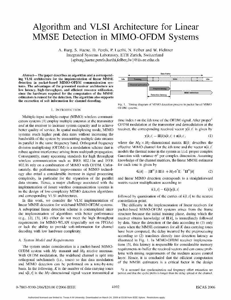
Data frameAbstract- The paper describes an algorithm and a correspond-
ing VLSI architecture for the implementation of linear MMSE Idle Dtat Idledetection in packet-based MIMO-OFDM communication sys-tems. The advantages of the presented receiver architecture arelow latency, high-throughput, and efficient resource utilization,
MIMO detectionisince the hardware required for the computation of the MMSE Detection latencyestimators is reused for the detection. The algorithm also supportsthe extraction of soft information for channel decoding.
Fig. 1. Timing diagram of MIMO detection process in packet-based MIMO-
I. INTRODUCTION OFDM systems.
Multiple-input multiple-output (MIMO) wireless communi-cation systems [1] employ multiple antennas at the transmitter time index t on the kth tone of the OFDM signal. After properand at the receiver to increase system capacity and to achieve OFDM modulation at the transmitter and demodulation at thebetter quality of service. In spatial multiplexing mode, MIMO receiver, the corresponding received vector y[k, t] is given bysystems reach higher peak data rates without increasing the y[k, t]= H[k]s[k, t] + n[k, t], (1)bandwidth of the system by transmitting multiple data streamsin parallel in the same frequency band. Orthogonal frequency where the MR X MT-dimensional matrix H[k] describes thedivision multiplexing (OFDM) is a modulation scheme that is effective MIMO channel for the kth tone and the vector n[k, t]robust against interference arising from multipath propagation. models the thermal noise in the system as i.i.d. proper complexConsequently, many upcoming standards for high throughput Gaussian with variance (Y per complex dimension. Assumingwireless communication such as IEEE 802.1 in and IEEE knowledge of the channel matrices, the linear MMSE estimator802.16 rely on a combination of MIMO with OFDM. Unfor- for each tone is given bytunately, the performance improvements of MIMO technol- G[k] = (HH [k]H[k] +MT 2I) l HH[k] (2)ogy also entail a considerable increase in signal processingcomplexity, in particular for the separation of the parallel and linear MIMO detection corresponds to a straightforwarddata streams. Hence, a major challenge associated with the matrix-vector multiplication according toimplementation of future wireless communication systems isin the design of low-complexity MIMO detection algorithms s[k,t] G[k]y[k,t] (3)and corresponding VLSI architectures. followed by quantization of the entries of s[k, t] to the nearest
In this work, we consider the VLSI implementation of constellation point.linear MMSE detection for wideband MIMO-OFDM systems. The difficulty in the implementation of linear receivers forA suboptimal linear detection scheme is contemplated since packet-based MIMO-OFDM systems arises from the framethe implementation of algorithms with better performance structure because the initial training phase, during which the(e.g., [2], [3], [4]) either do not meet the high throughput receiver obtains knowledge of H[k], is immediately followedrequirements for MIMO-WLAN (especially not on FPGAs) by data. Since the detection of the data according to (3) onlyor lack the ability to provide soft-information for channel starts when the MMSE estimators for all K data carrying tonesdecoding with low hardware complexity. have been computed, the delay incurred by the preprocessing
according to (2) translates directly into detection latency asA. System Model and Requirements illustrated in Fig. 1. In MIMO-OFDM receiver implementa-
The system under consideration is a packet-based MIMO- tions [5], this latency is responsible for considerable memoryrequirements to buffer the received vectors and can cause prob-OFDM systemwtth MT transmit and MR recetve antennas. par than th-eA
0-7803-9390-2/06/$20.00~~~lem ©2006 IEEEn 4102emnt ISCA2006duacsscnto
Authorized licensed use limited to: Texas A M University. Downloaded on March 24, 2009 at 03:08 from IEEE Xplore. Restrictions apply.

of packet-based MIMO-OFDM receivers. However, it is also number of multiplications2 and divisions is given bynoted that the corresponding operation is only performed once 5 2T5 2at the start of the frame so that, without special provisions, the CMult =2MRMT + 5MRM -MT +MTpotentially costly hardware for the preprocessing will be idle CDiv2MR (6)most of the time.
Contribution: In this paper an algorithm for efficient tone- In order to map recursion (5) to hardware, its compactby-tone linear preprocessing of channel state information in mathematical description is expanded as shown in Alg. 1. TheMIMO-OFDM systems is presented, together with a hardware- operation sequence is designed to reduce the dynamic rangeefficient VLSI architecture for its realization. The described of intermediate results and to minimize the number of costlyreceiver constitutes the basis for the soft-output demapper divisions, while keeping the number of multiplications low.described in [6] which yields a 5-6 dB gain in terms of signalto noise ratio (SNR) over a hard-decision MMSE decoder. Algorithm 1 Algorithm for computing the MMSE estimatorThe reported ASIC and FPGA area and performance figures P(M) 1l Iprovide reference for the true silicon complexity of linear for MT6M2lfrj=I...MR doMMSE receivers for MIMO-OFDM systems. 3 g =P(j-i)HH
Outline: The next section introduces the algorithm for 4: S= 1 + Hj (note that S is strictly positive)the computation of the linear MMSE detectors. Section III 5: Se elog25S - 2Sel/describes a scalable VLSI architecture for the proposed al- 6: g = 5mggorithm. Area and performance figures for ASIC and FPGA 7: p(j) = p(j-1) - ggH2-Seimplementations are provided in Section IV. Section V con- 8: end forcludes the paper. 9: G =P(MR)HH
II. PREPROCESSING ALGORITHM III. VLSI ARCHITECTURE
Algorithm choices for the implementation of (2) are either The choice of a suitable hardware architecture for the
based on QR-decomposition [7] using unitary transformations implementation of Alg. 1 depends on the system specificationsor on direct matrix inversion algorithms with conventional and on the available area: The most area efficient solutionarithmetic. The main advantages of the QR approach lie in its is a fully decomposed, processor-like architecture. However,favorable numerical properties in fixed-point implementations such a minimum-area solution cannot meet the low-latencyand in the availability of a wide range of regular array archi- requirements of MIMO-OFDM systems. A highly paralleltectures [8], [9] for their implementation. The main arguments architecture achieves higher throughput but suffers signifi-for direct matrix inversion are the lower number of operations cantly from the fact that data dependencies and the desirecompared to QR decomposition and the fact that the matrix for a regular data flow mandate a sequential execution of the
(HH [k]H[k] +MTG2I) I is produced as an intermediate result. individual steps in Alg. 1. Since these steps differ significantlyIn fact, the diagonal entries of this matrix are required for the in the number of required operations, a massively parallelcomputation of soft-outputs [10], [6]. architecture would result in a poor utilization of processingThe implementation that is described in this paper relies resources. In a moderately parallel VLSI architecture the
number of processing resources is chosen so that their averageon direct matrix inversion. The corresponding algorithm iS utlzto. shg.Moto.h tp nAl.1rqieeteborrowed from the updating procedure of the Kalman gain inKalman filtering applications. The basic idea is to start from MT or a multiple Of MT multiplications. Hence, choosingthe trivial inverse Of MT.2I and to obtain (HHH + MTG2I) 1 an MT-fold degree of parallelism leads to a high hardware
utilization.through a series of MR rank-one updates by using the matrixinversion lemma. The iteration is initialized by setting A. Moderately Parallel Architecture
The high-level block diagram of the proposed moderatelyp(O)
M1 I (4) parallel architecture is shown in Fig. 2. The circuit employsMTG2 MT identical processing elements (PEs) arranged in a circular
and proceeds by computing array and a common 1/ Y-block that computes the additions instep 4) and the pseudo floating-point division in step 5). The
HH p(j-l) connections in the array are local, meaning that only neigh-p(i) =p(i-1) HI iH.Pi ' (5) boring PEs are connected with each other. Each PE mainly
V 1 + HHP(j-1)HH'i contains a complex-valued multiplier, an adder and some localstorage registers as shown in Fig. 3. All intermediate variables
where H1 denotes the jth row of H. After MR iterations, are stored locally, equally distributed over the PBs. For the
p(MR)~~~~~~~~~~ .HH+MGI n(R H hr h 21n terms of complex-valued multiplications. The few real-valued mul-
index of the OFDM tone has been omitted for brevity. The tiplications are counted as complex-valued, assuming a dedicated VLSIcomplexity of the above described algorithm in terms of the architecture with multipliers optimized for complex-valued coefficients.
4103
Authorized licensed use limited to: Texas A M University. Downloaded on March 24, 2009 at 03:08 from IEEE Xplore. Restrictions apply.

PE(1) PH'l 4P4,2"j 2 P3,3 P2,4 [PHj]I27 t | zt z t| z t PE(3) _31 jl+22j2+l3j3<P H g [PHj&13
PE(4) P32HI12 +P2,3HH +P3,4Hf = [PH&14Fr r s r r ' X S r fl X r wr wr tm ~~~~~~~~~~~~~~~~~~~CyclesPE(1 ) PE(2) PE(i) PE(MT) Fig. 4. Procedure to compute step 3) in Ag. 1 for MT 4.
__L*L*~~~~~~~~~~~~~~~~~~~~~~~~~~~~~~~~~~~~~~~~~~~~~~~~~~~~~~~~~~~~~~~~~~~~~~~~~~~~~~~~~~~~~~~~~~~~~~~~~~~~~~~~~~~~~~~~~~~~~~~~~~~~~~~~~~~~~~~~~~~~~~~~~~~~~~~~~~~~~~~~~~~E414_Lj--. ,$_ It %
,1 , ~~,~~~~~~~~~~~~~~~~~ , result again into the g register of the neighboring PB. Thisp I Procedure is repeated for MT cycles with the exception of
P EE ) the first iteration (j 1) in which a single cycle suffices tocompute g, since P(°) is a diagonal matrix. The multiplications
Fig. 2. High-level block diagram of a moderately parallel architecture for the in step 4) can be carried out on all PBs in parallel in a singledirect matrix inversion. The same hardware is reused for the linear detection. cycle. The summation of the results that yields S is absorbed
raiinto the 1/ block, which performs the addition and the_ _ H Ypdivision in step 5) in CDiV cycles. The computation of g from g
inst iseagin striva ancain ibe performed ina single cycleFig 2 Hih-eve bockdigra o a odratlyparlll achtecur fo teon teidvuaPB.step7) isb carried outo l E inMTacyclesinasnl
_ ~~~~~~~ Sm each of wvhich one entry of g iS broadcasted to all PBs through
inotheupperbring, whiecirclaestrfoughthe lditowe ring.th
~~~~~~~~~~~~~~~~Before step 9) is executed, the diagonal entries of P can be
I I T Lolonal ~~~~~~extracted for the computation of soft bit-metrics, as describedl d o inppeline in [6]. Thepmatrixmultiplication ofgkRI with H is computedlI IIregister in a series of MR matrix-vector multiplications each of which
o_ _ __ is identical to step 3). The entries of H are again applied toLztj / | |Itheinputs of thePEs row-by-rowso that G is outout column-
wise, as shown in Fig. 2. The jth row of H can be replaced
withacthedjorthcolmpuainofG,s thatnoietramemorycs is requrired
into store the MMSE estimators This eMR o i aon is
p ~~~ ~ ~ ~~~priculasryimpratwentenmeofM mtiveorulpictiones isc lage Thec
MI IsIdToverallnumber of cyclesThatris requir ed toompute Alg. 1with the presented architecture is given by
| LEn 1 S ~~~~~~~tcpd=MR(3MT +2)-MT + 1 +MRCDiV. (7)
| 1 - X l ~~~~~~~~c.DetectionMTU wise,A significant advantage of the described conventional arith-
metic based computation of the MMSE estimator is that onceFig. 3. Schematic of a single PE. The main components are the complex- *prepro s ispomplete, the sameh w ane belrgeue
~~~~~~~~~~~~~~~oveallumerdo multlier,thati rdequired tohomue loalrgst.I
afor the detection according to (3). To this end, G is read back
from the memory one column at a time. The entries of the jthHermitian matrix P, only the main diagonal and the lower column are presented to the PBs together with the jth entrytriangular part are stored. of the received vector y which is broadcasted to all PBs. The
results of the multiplications of Gij with Yj in the ith PB areB. MMSE Estimator Computation accumulated in theav register of the same PB and s is available
The computation of the MMSE estimators starts with the after MR cycles.loop between step 2) and 8) in Alg. 1. During the jth iterationof this loop, the entries of the jth row of H must be presented Df Pipeliningto the inputs of the PBs as shown in Fig. 2. The computation Despite the recursive nature of the applied algorithm,of the matrix-vector multiplication in step 3) is illustrated in pipelining can be introduced to allow for higher clock frequen-Fig. 4. In the first cycle, the first PB uses the upper ring to cies. An additional register is added to the original architecturebroadcast H1,1 to all other PBs which multiply H1,1 with their as shown in Fig. 3. The actual increase in clock speed dependsrespective entry of the first column of p(i-r) and store the on the quality of the placement of this pipeline register in theresult in the g register of the neighboring PB. In the second logic. Implementation results show that a factor of almost 1.7cycle, the second PB broadcasts Ho2 to the other PBs, which can easily be reached with manual retiming. Unfortunately,multiply it with the respective entries of the second column pipelining of the recursive matrix inversion algorithm alsoof p(4.), add the content of their g register and forward the mandates the insertion of additional cycles to flush the pipeline
4104
Authorized licensed use limited to: Texas A M University. Downloaded on March 24, 2009 at 03:08 from IEEE Xplore. Restrictions apply.

1010T Ntpie°e FPGA Implementation. For the implementation of the de-4Nopipelined 6 sign (for MT = MR = 4) on a XILINX XC2V6000-6 FPGA,
WW Area Time/Inv. WW = 18 was chosen as the device contains hardwired multi-18 69k 0.68 ,us O pliers of that size. The pipelined version operates with a clock1
t75k 0.72 ,ls B rate of 40 MHz and requires 2.2 ps to compute the MMSE
~1c 21 85k0_ 74_s_|_A_ estimator of one tone. Hence, for example, the detection______ ______ ______ ______ ______ latency in a system with K= 64 tones adds up to 141 ps. The
_ _ _ throughput in detection mode is 10 Mvps. In terms of area,the design consumes 16 out of 144 multipliers and 3'416 logicslices out of a total of 33'792.
1 0 Pp_P;elined iW=18 V. CONCLUSIONSCDiv = 8Tmecpd --v. WW=_1_9 In packet-based MIMO-OFDM systems even allegedly low-
18 Area TmE/v.58 , WW-20 complexity linear detectors pose a considerable implementa-1_9 78k GE 0.6 ,us\ WW=21 tion challenge. The presented algorithm and the scalable VLSI20 82k GE 0.6 ,us 'Floating- architecture for the computation of the MMSE estimators
-3 21 -89k GE 0.61[,us point____10o 1 0 25 30s35o 40 partially solve this problem for MIMO-OFDM systems with a10 15 20 25 30 35 40SNR small number of tones (K < 64). A first important advantage of
the presented approach is that it reduces silicon area by reusingFig. 5. Fixed-point BER simulation and VLSI implementation results the same hardware for the preprocessing and the for thefor MMSE detection in a system with MT = MR = 4 and with 16-QAM detection. The second advantage is the ability to easily extractmodulation. soft bit-metrics for a subsequent channel decoder [6]. The
main drawback are the considerable numerical requirements.Moreover, it is noted that for systems with a large number
after the operations associated with steps 3), 4), 6), 7) and 9) of tones, preprocessing latency is still too high. A possibleof Alg. 1. As a result, the number of cycles increases to solution to this problem has recently been proposed in [11].
tCPd = MR (3MT +6) -MT + 2+ MRCDiV (8) ACKNOWLEDGEMENTThis work is supported by the STREP project No. IST-
and the number of cycles for the division must also be 026905 (MASCOT) within the sixth framework programmeincreased to match the higher clock rate. of the European Commission.
REFERENCESIV. IMPLEMENTATION RESULTS [1] G. Foschini and M. Gans, "On limits of wireless communications in a
fading environment when using multiple antennas," Wireless PersonalASIC A critical design parameter is the Communications, vol. 6, no. 3, pp. 311-334, 1998.ASICImplementation. A crlhcal deslgn parameter 1S the [2] Z. Guo and P. Nilsson, "A 53.3 Mb/s 4 x 4 16-QAM MIMO decoder in
wordlength of the complex-valued datapath. The correspond- 0.35pm CMOS," in Proc. IEEE ISCAS, May 2005, pp. 4947-4950.ing trade-offs between silicon area, bit error rate (BER) perfor- [3] A. Burg, M. Borgmann, M. Wenk, M. Zellweger, W. Fichtner, and
mance, and the computationtieforasingleMMSH. B6lcskei, "VLSI implementation of MIMO detection using the spheremance, and the computation time for a single MMSE estimator decoder algorithm," IEEE Journal of Solid-State Circuits, 2005.is illustrated in Fig. 5 for a system with MT = MR = 4. [4] M. Wenk, M. Zellweger, A. Burg, N. Felber, and W. Fichtner, "K-BestThe VLSI implementation results are based on a 0.25 pm MIMO detection VLSI architectures achieving up to 424 Mbps," in Proc.
technology and for th BERsimulationstheentIEEE Int. Symp. on Circuits and Systems, May 2006.technology and for the BER simulations the entries of H[k] [5] D. Perels, S. Haene, P. Luethi, A. Burg, N. Felber, W. Fichtner, andare assumed i.i.d. Rayleigh fading with variance one, so that H. B6lcskei, "ASIC implementation of a MIMO-OFDM transceiver forthe received SNR is given by 17/2. For the computation of 192 mbps WLANs," in Proc. IEEE ESSCIRC, Sept. 2005, pp. 215-218.the MMSE estimator, H[k] is represented in a block floating- [6] s. Haene, A. Burg, D. Perels, P. Luethi, N. Felber, and W. Fichtner,
"Silicon implementation of an MMSE-based soft demapper for MIMO-point format and WW denotes the wordwidth of the real-valued BICM," in Proc. IEEE Int. Symp. on Circuits and Systems, May 2006.multipliers which constitute the complex-valued multipliers [7] Z. Khan, T. Arslan, J. S. Thompson, and A. T. Erdogan, "Area & powerin the PEs. The clock rates of the unpipelined designs are
efficient VLSI architecture for computing pseudo inverse of channelln t PsT ccrsfhu pnamatrix in a MIMO wireless system," in Proc. IEEE Int. Conf on VLSIbetween 93 MHz and 101 MHz, depending on the wordlength. Design (VLSID), Jan. 2006, pp. 734-737.The pipelined implementations achieve between 167 MHz and [8] G. Lightbody, R. Woods, and R. Walke, "Design of a parameterized176 MHz. For the computation of the MMSE estimators, the silicon intellectual property core for QR-based RLS filtering," IEEE
Trans. on VLSI Systems, vol. 11, pp. 659-678, 2003.gain from the higher clock frequency remains small due to [9] F. Edman and V. Owall, "A scalable pipelined complex valued matrixthe increase in the number of cycles. However, a significant inversion architecture," in Proc. IEEE ISCAS, 2005, pp. 4489-4492.performance improvement is achieved from pipelining when [10] I. B. Collings, M. R. G. Butler, and M. McKay, "Low complexity re-
ceiver design for MIMO bit-interleaved coded modulation," in Proc. 8ththe circuit operates in detection mode, because during this IEEEInt. Symposium on Spread Spectrum Techniques and Applications,operation no pipeline bubbles need to be inserted. Without 2004, pp. 12-16.
.... . ~~~~~~~~~~~~~[11]D. Cescato, M. Borgmann, H. Boilcskei, J. C. Hansen, and A. Burg,pipelining, 23-25 millilon (received) vectors per second (Mvps) "Interpolation-based QR decomposition in MIMO-OFDM systems,"can be processed, while with pipelining throughput increases in Proc. IEEE Workshop on Signal Processing Advances in Wirelessto 42-44 Mvps. Communications (SPAWC), June 2005, pp. 945-949.
4105
Authorized licensed use limited to: Texas A M University. Downloaded on March 24, 2009 at 03:08 from IEEE Xplore. Restrictions apply.