alcatel-lucent 7705 service aggregation router … · table of contents page 4 7705 sar os router...
TRANSCRIPT

Alcatel-Lucent 7705SERVICE AGGREGATION ROUTER OS | RELEASE 2.0R O U T E R C O N F I G U R A T I O N G U I D E
Alcatel-Lucent ProprietaryThis document contains proprietary information of Alcatel-Lucent and is not to be disclosedor used except in accordance with applicable agreements.Copyright 2009 © Alcatel-Lucent. All rights reserved.

When printed by Alcatel-Lucent, this document is printed on recycled paper.
Alcatel-Lucent assumes no responsibility for the accuracy of the information presented, which is subject to change without notice.
Alcatel, Lucent, Alcatel-Lucent and the Alcatel-Lucent logo are trademarks of Alcatel-Lucent. All other trademarks are the property of their respective owners.
Copyright 2009 Alcatel-Lucent.All rights reserved.
Disclaimers
Alcatel-Lucent products are intended for commercial uses. Without the appropriate network design engineering, they must not be sold, licensed or otherwise distributed for use in any hazardous environments requiring fail-safe performance, such as in the operation of nuclear facilities, aircraft navigation or communication systems, air traffic control, direct life-support machines, or weapons systems, in which the failure of products could lead directly to death, personal injury, or severe physical or environmental damage. The customer hereby agrees that the use, sale, license or other distribution of the products for any such application without the prior written consent of Alcatel-Lucent, shall be at the customer's sole risk. The customer hereby agrees to defend and hold Alcatel-Lucent harmless from any claims for loss, cost, damage, expense or liability that may arise out of or in connection with the use, sale, license or other distribution of the products in such applications.
This document may contain information regarding the use and installation of non-Alcatel-Lucent products. Please note that this information is provided as a courtesy to assist you. While Alcatel-Lucent tries to ensure that this information accurately reflects information provided by the supplier, please refer to the materials provided with any non-Alcatel-Lucent product and contact the supplier for confirmation. Alcatel-Lucent assumes no responsibility or liability for incorrect or incomplete information provided about non-Alcatel-Lucent products.
However, this does not constitute a representation or warranty. The warranties provided for Alcatel-Lucent products, if any, are set forth in contractual documentation entered into by Alcatel-Lucent and its customers.
This document was originally written in English. If there is any conflict or inconsistency between the English version and any other version of a document, the English version shall prevail.

Table of Contents
Preface . . . . . . . . . . . . . . . . . . . . . . . . . . . . . . . . . . . . . . . . . . . . . . . . . . . . . . . . . . . . . . . . . . . . . . . . . 21
Getting Started . . . . . . . . . . . . . . . . . . . . . . . . . . . . . . . . . . . . . . . . . . . . . . . . . . . . . . . . . . . . . . . . . . . 23Alcatel-Lucent 7705 SAR Router Configuration Process . . . . . . . . . . . . . . . . . . . . . . . . . . . . . . . . . . . . . . . . . 23
Notes on 7705 SAR-8 and 7705 SAR-F . . . . . . . . . . . . . . . . . . . . . . . . . . . . . . . . . . . . . . . . . . . . . . . . . . . 24
IP Router Configuration . . . . . . . . . . . . . . . . . . . . . . . . . . . . . . . . . . . . . . . . . . . . . . . . . . . . . . . . . . . 27Configuring IP Router Parameters . . . . . . . . . . . . . . . . . . . . . . . . . . . . . . . . . . . . . . . . . . . . . . . . . . . . . . . . . . 28
Interfaces . . . . . . . . . . . . . . . . . . . . . . . . . . . . . . . . . . . . . . . . . . . . . . . . . . . . . . . . . . . . . . . . . . . . . . . . . . 28Network Interface . . . . . . . . . . . . . . . . . . . . . . . . . . . . . . . . . . . . . . . . . . . . . . . . . . . . . . . . . . . . . . . . . . 28System Interface. . . . . . . . . . . . . . . . . . . . . . . . . . . . . . . . . . . . . . . . . . . . . . . . . . . . . . . . . . . . . . . . . . . 30
IP Addresses . . . . . . . . . . . . . . . . . . . . . . . . . . . . . . . . . . . . . . . . . . . . . . . . . . . . . . . . . . . . . . . . . . . . . . . . 30Router ID . . . . . . . . . . . . . . . . . . . . . . . . . . . . . . . . . . . . . . . . . . . . . . . . . . . . . . . . . . . . . . . . . . . . . . . . . . . 31Static Routes, OSPF Routes and ECMP . . . . . . . . . . . . . . . . . . . . . . . . . . . . . . . . . . . . . . . . . . . . . . . . . . 31Bidirectional Forwarding Detection (BFD) . . . . . . . . . . . . . . . . . . . . . . . . . . . . . . . . . . . . . . . . . . . . . . . . . . 32
Router Configuration Process Overview . . . . . . . . . . . . . . . . . . . . . . . . . . . . . . . . . . . . . . . . . . . . . . . . . . . . . . 33Configuration Notes . . . . . . . . . . . . . . . . . . . . . . . . . . . . . . . . . . . . . . . . . . . . . . . . . . . . . . . . . . . . . . . . . . . . . 34
Reference Sources . . . . . . . . . . . . . . . . . . . . . . . . . . . . . . . . . . . . . . . . . . . . . . . . . . . . . . . . . . . . . . . . . . . 34Configuring an IP Router with CLI. . . . . . . . . . . . . . . . . . . . . . . . . . . . . . . . . . . . . . . . . . . . . . . . . . . . . . . . . . . 35Router Configuration Overview . . . . . . . . . . . . . . . . . . . . . . . . . . . . . . . . . . . . . . . . . . . . . . . . . . . . . . . . . . . . . 36
System Interface . . . . . . . . . . . . . . . . . . . . . . . . . . . . . . . . . . . . . . . . . . . . . . . . . . . . . . . . . . . . . . . . . . . . . 36Network Interface . . . . . . . . . . . . . . . . . . . . . . . . . . . . . . . . . . . . . . . . . . . . . . . . . . . . . . . . . . . . . . . . . . . . 37
Basic Configuration . . . . . . . . . . . . . . . . . . . . . . . . . . . . . . . . . . . . . . . . . . . . . . . . . . . . . . . . . . . . . . . . . . . . . . 38Common Configuration Tasks. . . . . . . . . . . . . . . . . . . . . . . . . . . . . . . . . . . . . . . . . . . . . . . . . . . . . . . . . . . . . . 39
Configuring a System Name . . . . . . . . . . . . . . . . . . . . . . . . . . . . . . . . . . . . . . . . . . . . . . . . . . . . . . . . . . . . 39Configuring Interfaces . . . . . . . . . . . . . . . . . . . . . . . . . . . . . . . . . . . . . . . . . . . . . . . . . . . . . . . . . . . . . . . . . 40
Configuring a System Interface . . . . . . . . . . . . . . . . . . . . . . . . . . . . . . . . . . . . . . . . . . . . . . . . . . . . . . . 40Configuring a Network Interface . . . . . . . . . . . . . . . . . . . . . . . . . . . . . . . . . . . . . . . . . . . . . . . . . . . . . . . 40
Configuring ECMP . . . . . . . . . . . . . . . . . . . . . . . . . . . . . . . . . . . . . . . . . . . . . . . . . . . . . . . . . . . . . . . . . . . 41Configuring Static Routes . . . . . . . . . . . . . . . . . . . . . . . . . . . . . . . . . . . . . . . . . . . . . . . . . . . . . . . . . . . . . . 42Configuring or Deriving a Router ID . . . . . . . . . . . . . . . . . . . . . . . . . . . . . . . . . . . . . . . . . . . . . . . . . . . . . . 42
Service Management Tasks . . . . . . . . . . . . . . . . . . . . . . . . . . . . . . . . . . . . . . . . . . . . . . . . . . . . . . . . . . . . . . . 44Changing the System Name . . . . . . . . . . . . . . . . . . . . . . . . . . . . . . . . . . . . . . . . . . . . . . . . . . . . . . . . . . . . 44Modifying Interface Parameters . . . . . . . . . . . . . . . . . . . . . . . . . . . . . . . . . . . . . . . . . . . . . . . . . . . . . . . . . 45Deleting a Logical IP Interface . . . . . . . . . . . . . . . . . . . . . . . . . . . . . . . . . . . . . . . . . . . . . . . . . . . . . . . . . . 46
IP Router Command Reference . . . . . . . . . . . . . . . . . . . . . . . . . . . . . . . . . . . . . . . . . . . . . . . . . . . . . . . . . . . . 47Command Hierarchies . . . . . . . . . . . . . . . . . . . . . . . . . . . . . . . . . . . . . . . . . . . . . . . . . . . . . . . . . . . . . . . . 47Command Descriptions . . . . . . . . . . . . . . . . . . . . . . . . . . . . . . . . . . . . . . . . . . . . . . . . . . . . . . . . . . . . . . . . 51
Configuration Commands . . . . . . . . . . . . . . . . . . . . . . . . . . . . . . . . . . . . . . . . . . . . . . . . . . . . . . . . . . . . 52Show Commands . . . . . . . . . . . . . . . . . . . . . . . . . . . . . . . . . . . . . . . . . . . . . . . . . . . . . . . . . . . . . . . . . . 70Clear Commands . . . . . . . . . . . . . . . . . . . . . . . . . . . . . . . . . . . . . . . . . . . . . . . . . . . . . . . . . . . . . . . . . . 89Debug Commands . . . . . . . . . . . . . . . . . . . . . . . . . . . . . . . . . . . . . . . . . . . . . . . . . . . . . . . . . . . . . . . . . 91
Filter Policies . . . . . . . . . . . . . . . . . . . . . . . . . . . . . . . . . . . . . . . . . . . . . . . . . . . . . . . . . . . . . . . . . . . . 95Configuring Filter Policies . . . . . . . . . . . . . . . . . . . . . . . . . . . . . . . . . . . . . . . . . . . . . . . . . . . . . . . . . . . . . . . . . 96
Network Interface-based Filtering . . . . . . . . . . . . . . . . . . . . . . . . . . . . . . . . . . . . . . . . . . . . . . . . . . . . . . . . 96
7705 SAR OS Router Configuration Guide Page 3

Table of Contents
Filter Policy Entities . . . . . . . . . . . . . . . . . . . . . . . . . . . . . . . . . . . . . . . . . . . . . . . . . . . . . . . . . . . . . . . . . . . 97Applying Filter Policies . . . . . . . . . . . . . . . . . . . . . . . . . . . . . . . . . . . . . . . . . . . . . . . . . . . . . . . . . . . . . . 97Packet Matching Criteria. . . . . . . . . . . . . . . . . . . . . . . . . . . . . . . . . . . . . . . . . . . . . . . . . . . . . . . . . . . . . 98Ordering Filter Entries. . . . . . . . . . . . . . . . . . . . . . . . . . . . . . . . . . . . . . . . . . . . . . . . . . . . . . . . . . . . . . 100
Filter Logs . . . . . . . . . . . . . . . . . . . . . . . . . . . . . . . . . . . . . . . . . . . . . . . . . . . . . . . . . . . . . . . . . . . . . . . . . 102Configuration Notes . . . . . . . . . . . . . . . . . . . . . . . . . . . . . . . . . . . . . . . . . . . . . . . . . . . . . . . . . . . . . . . . . . . . 103
IP Filters . . . . . . . . . . . . . . . . . . . . . . . . . . . . . . . . . . . . . . . . . . . . . . . . . . . . . . . . . . . . . . . . . . . . . . . . . . 103Filter Logs . . . . . . . . . . . . . . . . . . . . . . . . . . . . . . . . . . . . . . . . . . . . . . . . . . . . . . . . . . . . . . . . . . . . . . . . . 103Reference Sources . . . . . . . . . . . . . . . . . . . . . . . . . . . . . . . . . . . . . . . . . . . . . . . . . . . . . . . . . . . . . . . . . . 104
Configuring Filter Policies with CLI . . . . . . . . . . . . . . . . . . . . . . . . . . . . . . . . . . . . . . . . . . . . . . . . . . . . . . . . . 105Basic Configuration . . . . . . . . . . . . . . . . . . . . . . . . . . . . . . . . . . . . . . . . . . . . . . . . . . . . . . . . . . . . . . . . . . . . . 106Common Configuration Tasks. . . . . . . . . . . . . . . . . . . . . . . . . . . . . . . . . . . . . . . . . . . . . . . . . . . . . . . . . . . . . 107
Creating an IP Filter Policy . . . . . . . . . . . . . . . . . . . . . . . . . . . . . . . . . . . . . . . . . . . . . . . . . . . . . . . . . . . . 107IP Filter Policy. . . . . . . . . . . . . . . . . . . . . . . . . . . . . . . . . . . . . . . . . . . . . . . . . . . . . . . . . . . . . . . . . . . . 107IP Filter Entry . . . . . . . . . . . . . . . . . . . . . . . . . . . . . . . . . . . . . . . . . . . . . . . . . . . . . . . . . . . . . . . . . . . . 109IP Filter Entry Matching Criteria . . . . . . . . . . . . . . . . . . . . . . . . . . . . . . . . . . . . . . . . . . . . . . . . . . . . . . 110
Configuring Filter Log Policies . . . . . . . . . . . . . . . . . . . . . . . . . . . . . . . . . . . . . . . . . . . . . . . . . . . . . . . . . 111Applying Filter Policies to Network Interfaces . . . . . . . . . . . . . . . . . . . . . . . . . . . . . . . . . . . . . . . . . . . . . 111
Apply a Filter Policy to an Interface . . . . . . . . . . . . . . . . . . . . . . . . . . . . . . . . . . . . . . . . . . . . . . . . . . . 111Filter Management Tasks . . . . . . . . . . . . . . . . . . . . . . . . . . . . . . . . . . . . . . . . . . . . . . . . . . . . . . . . . . . . . . . . 113
Renumbering Filter Policy Entries . . . . . . . . . . . . . . . . . . . . . . . . . . . . . . . . . . . . . . . . . . . . . . . . . . . . . . . 113Modifying an IP Filter Policy . . . . . . . . . . . . . . . . . . . . . . . . . . . . . . . . . . . . . . . . . . . . . . . . . . . . . . . . . . . 115Deleting a Filter Policy . . . . . . . . . . . . . . . . . . . . . . . . . . . . . . . . . . . . . . . . . . . . . . . . . . . . . . . . . . . . . . . 116
Deleting a Filter from a Network Interface . . . . . . . . . . . . . . . . . . . . . . . . . . . . . . . . . . . . . . . . . . . . . . 116Deleting a Filter. . . . . . . . . . . . . . . . . . . . . . . . . . . . . . . . . . . . . . . . . . . . . . . . . . . . . . . . . . . . . . . . . . . 116
Filter Command Reference . . . . . . . . . . . . . . . . . . . . . . . . . . . . . . . . . . . . . . . . . . . . . . . . . . . . . . . . . . . . . . 117Command Hierarchies . . . . . . . . . . . . . . . . . . . . . . . . . . . . . . . . . . . . . . . . . . . . . . . . . . . . . . . . . . . . . . . 117Command Descriptions . . . . . . . . . . . . . . . . . . . . . . . . . . . . . . . . . . . . . . . . . . . . . . . . . . . . . . . . . . . . . . . 120
Configuration Commands . . . . . . . . . . . . . . . . . . . . . . . . . . . . . . . . . . . . . . . . . . . . . . . . . . . . . . . . . . . 121Show Commands . . . . . . . . . . . . . . . . . . . . . . . . . . . . . . . . . . . . . . . . . . . . . . . . . . . . . . . . . . . . . . . . . 139Clear Commands . . . . . . . . . . . . . . . . . . . . . . . . . . . . . . . . . . . . . . . . . . . . . . . . . . . . . . . . . . . . . . . . . 147Monitor Commands . . . . . . . . . . . . . . . . . . . . . . . . . . . . . . . . . . . . . . . . . . . . . . . . . . . . . . . . . . . . . . . 148
Route Policies . . . . . . . . . . . . . . . . . . . . . . . . . . . . . . . . . . . . . . . . . . . . . . . . . . . . . . . . . . . . . . . . . . 149Configuring Route Policies . . . . . . . . . . . . . . . . . . . . . . . . . . . . . . . . . . . . . . . . . . . . . . . . . . . . . . . . . . . . . . . 150
Policy Statements . . . . . . . . . . . . . . . . . . . . . . . . . . . . . . . . . . . . . . . . . . . . . . . . . . . . . . . . . . . . . . . . . . . 151Default Action Behavior . . . . . . . . . . . . . . . . . . . . . . . . . . . . . . . . . . . . . . . . . . . . . . . . . . . . . . . . . . . . 151Denied IP Prefixes . . . . . . . . . . . . . . . . . . . . . . . . . . . . . . . . . . . . . . . . . . . . . . . . . . . . . . . . . . . . . . . . 152
Route Policy Configuration Process Overview . . . . . . . . . . . . . . . . . . . . . . . . . . . . . . . . . . . . . . . . . . . . . . . . 153Configuration Notes . . . . . . . . . . . . . . . . . . . . . . . . . . . . . . . . . . . . . . . . . . . . . . . . . . . . . . . . . . . . . . . . . . . . 154
Reference Sources . . . . . . . . . . . . . . . . . . . . . . . . . . . . . . . . . . . . . . . . . . . . . . . . . . . . . . . . . . . . . . . . . . 154Configuring Route Policies with CLI . . . . . . . . . . . . . . . . . . . . . . . . . . . . . . . . . . . . . . . . . . . . . . . . . . . . . . . . 155Route Policy Configuration Overview . . . . . . . . . . . . . . . . . . . . . . . . . . . . . . . . . . . . . . . . . . . . . . . . . . . . . . . 156
When to Create Routing Policies . . . . . . . . . . . . . . . . . . . . . . . . . . . . . . . . . . . . . . . . . . . . . . . . . . . . . . . 156Policy Evaluation . . . . . . . . . . . . . . . . . . . . . . . . . . . . . . . . . . . . . . . . . . . . . . . . . . . . . . . . . . . . . . . . . . . . 157
Basic Route Policy Configuration . . . . . . . . . . . . . . . . . . . . . . . . . . . . . . . . . . . . . . . . . . . . . . . . . . . . . . . . . . 159Configuring Route Policy Components . . . . . . . . . . . . . . . . . . . . . . . . . . . . . . . . . . . . . . . . . . . . . . . . . . . . . . 160
Beginning the Policy Statement . . . . . . . . . . . . . . . . . . . . . . . . . . . . . . . . . . . . . . . . . . . . . . . . . . . . . . . . 160Creating a Route Policy . . . . . . . . . . . . . . . . . . . . . . . . . . . . . . . . . . . . . . . . . . . . . . . . . . . . . . . . . . . . . . 161
Page 4 7705 SAR OS Router Configuration Guide
Table of Contents
Configuring a Default Action . . . . . . . . . . . . . . . . . . . . . . . . . . . . . . . . . . . . . . . . . . . . . . . . . . . . . . . . . . 162Configuring an Entry . . . . . . . . . . . . . . . . . . . . . . . . . . . . . . . . . . . . . . . . . . . . . . . . . . . . . . . . . . . . . . . . . 163Configuring a Prefix List . . . . . . . . . . . . . . . . . . . . . . . . . . . . . . . . . . . . . . . . . . . . . . . . . . . . . . . . . . . . . . 165
Route Policy Configuration Management Tasks. . . . . . . . . . . . . . . . . . . . . . . . . . . . . . . . . . . . . . . . . . . . . . . 166Editing Policy Statements and Parameters . . . . . . . . . . . . . . . . . . . . . . . . . . . . . . . . . . . . . . . . . . . . . . . 166Deleting an Entry . . . . . . . . . . . . . . . . . . . . . . . . . . . . . . . . . . . . . . . . . . . . . . . . . . . . . . . . . . . . . . . . . . . 167Deleting a Policy Statement . . . . . . . . . . . . . . . . . . . . . . . . . . . . . . . . . . . . . . . . . . . . . . . . . . . . . . . . . . . 168
Route Policy Command Reference . . . . . . . . . . . . . . . . . . . . . . . . . . . . . . . . . . . . . . . . . . . . . . . . . . . . . . . . 169Command Hierarchies . . . . . . . . . . . . . . . . . . . . . . . . . . . . . . . . . . . . . . . . . . . . . . . . . . . . . . . . . . . . . . . 169Command Descriptions . . . . . . . . . . . . . . . . . . . . . . . . . . . . . . . . . . . . . . . . . . . . . . . . . . . . . . . . . . . . . . 171
Configuration Commands. . . . . . . . . . . . . . . . . . . . . . . . . . . . . . . . . . . . . . . . . . . . . . . . . . . . . . . . . . . 172Show Commands . . . . . . . . . . . . . . . . . . . . . . . . . . . . . . . . . . . . . . . . . . . . . . . . . . . . . . . . . . . . . . . . . 184
Standards and Protocol Support . . . . . . . . . . . . . . . . . . . . . . . . . . . . . . . . . . . . . . . . . . . . . . . . . . . 185
7705 SAR OS Router Configuration Guide Page 5

Table of Contents
Page 6 7705 SAR OS Router Configuration Guide

List of Tables
Getting Started . . . . . . . . . . . . . . . . . . . . . . . . . . . . . . . . . . . . . . . . . . . . . . . . . . . . . . . . . . . . . . . . . . . 23Table 1: Configuration Process . . . . . . . . . . . . . . . . . . . . . . . . . . . . . . . . . . . . . . . . . . . . . . . . . . . . . . . . . . . 23Table 2: 7705 SAR-8 and 7705 SAR-F Comparison . . . . . . . . . . . . . . . . . . . . . . . . . . . . . . . . . . . . . . . . . . . 24
IP Router Configuration . . . . . . . . . . . . . . . . . . . . . . . . . . . . . . . . . . . . . . . . . . . . . . . . . . . . . . . . . . . 27Table 3: Route Preference Defaults by Route Type . . . . . . . . . . . . . . . . . . . . . . . . . . . . . . . . . . . . . . . . . . . . 57Table 4: Show ARP Table Output Fields . . . . . . . . . . . . . . . . . . . . . . . . . . . . . . . . . . . . . . . . . . . . . . . . . . . . 70Table 5: Show Authentication Statistics Output Fields . . . . . . . . . . . . . . . . . . . . . . . . . . . . . . . . . . . . . . . . . . 72Table 6: Show BFD Interface Output Fields . . . . . . . . . . . . . . . . . . . . . . . . . . . . . . . . . . . . . . . . . . . . . . . . . . 73Table 7: Show BFD Session Output Fields . . . . . . . . . . . . . . . . . . . . . . . . . . . . . . . . . . . . . . . . . . . . . . . . . . 74Table 8: Show ECMP Settings Output Fields . . . . . . . . . . . . . . . . . . . . . . . . . . . . . . . . . . . . . . . . . . . . . . . . . 75Table 9: Show Standard IP Interface Output Fields . . . . . . . . . . . . . . . . . . . . . . . . . . . . . . . . . . . . . . . . . . . . 77Table 10: Show Detailed IP Interface Output Fields . . . . . . . . . . . . . . . . . . . . . . . . . . . . . . . . . . . . . . . . . . . . . 78Table 11: Show Summary IP Interfaces Output Fields . . . . . . . . . . . . . . . . . . . . . . . . . . . . . . . . . . . . . . . . . . . 80Table 12: Show Standard Route Table Output Fields . . . . . . . . . . . . . . . . . . . . . . . . . . . . . . . . . . . . . . . . . . . . 81Table 13: Show Static ARP Table Output Fields . . . . . . . . . . . . . . . . . . . . . . . . . . . . . . . . . . . . . . . . . . . . . . . 83Table 14: Show Static Route Table Output Fields . . . . . . . . . . . . . . . . . . . . . . . . . . . . . . . . . . . . . . . . . . . . . . 84Table 15: Show Router Status Output Fields . . . . . . . . . . . . . . . . . . . . . . . . . . . . . . . . . . . . . . . . . . . . . . . . . . 86Table 16: Show Tunnel Table Output Fields . . . . . . . . . . . . . . . . . . . . . . . . . . . . . . . . . . . . . . . . . . . . . . . . . . . 87
Filter Policies . . . . . . . . . . . . . . . . . . . . . . . . . . . . . . . . . . . . . . . . . . . . . . . . . . . . . . . . . . . . . . . . . . . . 95Table 17: Show Filter Output Fields . . . . . . . . . . . . . . . . . . . . . . . . . . . . . . . . . . . . . . . . . . . . . . . . . . . . . . . . 139Table 18: Show Filter Output Fields (Filter ID Specified) . . . . . . . . . . . . . . . . . . . . . . . . . . . . . . . . . . . . . . . . 140Table 19: Show Filter Associations Output Fields . . . . . . . . . . . . . . . . . . . . . . . . . . . . . . . . . . . . . . . . . . . . . 142Table 20: Show Filter Counters Output Fields . . . . . . . . . . . . . . . . . . . . . . . . . . . . . . . . . . . . . . . . . . . . . . . . 143Table 21: Show Filter Log Output Fields . . . . . . . . . . . . . . . . . . . . . . . . . . . . . . . . . . . . . . . . . . . . . . . . . . . . 145Table 22: Show Filter Log Bindings . . . . . . . . . . . . . . . . . . . . . . . . . . . . . . . . . . . . . . . . . . . . . . . . . . . . . . . . 146
Route Policies . . . . . . . . . . . . . . . . . . . . . . . . . . . . . . . . . . . . . . . . . . . . . . . . . . . . . . . . . . . . . . . . . . 149Table 23: Show Route Policy Output Fields . . . . . . . . . . . . . . . . . . . . . . . . . . . . . . . . . . . . . . . . . . . . . . . . . . 184
7705 SAR OS Router Configuration Guide Page 7

List of Tables
Page 8 7705 SAR OS Router Configuration Guide
List of Figures
IP Router Configuration . . . . . . . . . . . . . . . . . . . . . . . . . . . . . . . . . . . . . . . . . . . . . . . . . . . . . . . . . . . 27Figure 1: IP Router Configuration Flow . . . . . . . . . . . . . . . . . . . . . . . . . . . . . . . . . . . . . . . . . . . . . . . . . . . . . . 33
Filter Policies . . . . . . . . . . . . . . . . . . . . . . . . . . . . . . . . . . . . . . . . . . . . . . . . . . . . . . . . . . . . . . . . . . . . 95Figure 2: Creating and Applying Filter Policies . . . . . . . . . . . . . . . . . . . . . . . . . . . . . . . . . . . . . . . . . . . . . . . . 98Figure 3: Filtering Process Example . . . . . . . . . . . . . . . . . . . . . . . . . . . . . . . . . . . . . . . . . . . . . . . . . . . . . . . 101
Route Policies . . . . . . . . . . . . . . . . . . . . . . . . . . . . . . . . . . . . . . . . . . . . . . . . . . . . . . . . . . . . . . . . . . 149Figure 4: Route Policy Configuration and Implementation Flow . . . . . . . . . . . . . . . . . . . . . . . . . . . . . . . . . . 153Figure 5: Route Policy Process Example . . . . . . . . . . . . . . . . . . . . . . . . . . . . . . . . . . . . . . . . . . . . . . . . . . . 158
7705 SAR OS Router Configuration Guide Page 9

List of Figures
Page 10 7705 SAR OS Router Configuration Guide

List of Acronyms
Acronym Expansion
2G second generation wireless telephone technology
3DES triple DES (data encryption standard)
3G third generation mobile telephone technology
5620 SAM 5620 Service Aware Manager
7705 SAR 7705 Service Aggregation Router
ABR available bit ratearea border router
AC alternating currentattachment circuit
ACL access control list
ACR adaptive clock recovery
AIS alarm indication signal
ANSI American National Standards Institute
Apipe ATM VLL
ARP address resolution protocol
AS autonomous system
ASAP any service, any port
ASBR autonomous system boundary router
ATM asynchronous transfer mode
ATM PVC ATM permanent virtual circuit
Batt A battery A
B-bit beginning bit (first packet of a fragment)
Bellcore Bell Communications Research
BFD bidirectional forwarding detection
7705 SAR OS Router Configuration Guide Page 11

List of Acronyms
BITS building integrated timing supply
BOF boot options file
BRAS Broadband Remote Access Server
BSC Base Station Controller
BSTA Broadband Service Termination Architecture
BTS base transceiver station
CAS channel associated signaling
CBN common bonding networks
CBS committed buffer space
CC control channel
CE customer edgecircuit emulation
CEM circuit emulation
CES circuit emulation services
CESoPSN circuit emulation services over packet switched network
CIDR classless inter-domain routing
CIR committed information rate
CLI command line interface
CLP cell loss priority
CoS class of service
CPE customer premises equipment
Cpipe circuit emulation (or TDM) VLL
CPM Control and Processing Module (CPM is used instead of CSM when referring to CSM filtering � to align with CLI syntax used with other SR products)
CPU central processing unit
CRC cyclic redundancy check
Acronym Expansion
Page 12 7705 SAR OS Router Configuration Guide

List of Acronyms
CRON a time-based scheduling service (from chronos = time)
CSM Control and Switching Module
CSPF constrained shortest path first
CV connection verificationcustomer VLAN (tag)
CW control word
DC direct current
DC-C DC return - common
DC-I DC return - isolated
DCO digitally controlled oscillator
DDoS distributed DoS
DES data encryption standard
DHCP dynamic host configuration protocol
DNS domain name server
DoS denial of service
dot1q IEEE 802.1q encapsulation for Ethernet interfaces
DPLL digital phase locked loop
DSCP differentiated services code point
DSL digital subscriber line
DSLAM digital subscriber line access multiplexer
DTE data termination equipment
DU downstream unsolicited
e911 enhanced 911 service
E-bit ending bit (last packet of a fragment)
ECMP equal cost multi-path
EFM Ethernet in the first mile
Acronym Expansion
7705 SAR OS Router Configuration Guide Page 13

List of Acronyms
EGP exterior gateway protocol
ELER egress label edge router
Epipe Ethernet VLL
ERO explicit route object
ESD electrostatic discharge
ETE end-to-end
EVDO evolution - data optimized
EXP bits experimental bits
FC forwarding class
FCS frame check sequence
FDB forwarding database
FDL facilities data link
FEC forwarding equivalence class
FF fixed filter
FIB forwarding information base
FTN FEC-to-NHLFE
FTP file transfer protocol
GigE Gigabit Ethernet
GRE generic routing encapsulation
GSM Global System for Mobile Communications (2G)
HEC header error control
HMAC hash message authentication code
HSDPA high-speed downlink packet access
HSPA high-speed packet access
IBN isolated bonding networks
ICMP Internet control message protocol
Acronym Expansion
Page 14 7705 SAR OS Router Configuration Guide

List of Acronyms
ICP IMA control protocol cells
IEEE Institute of Electrical and Electronics Engineers
IES Internet Enhanced Service
IETF Internet Engineering Task Force
IGP interior gateway protocol
ILER ingress label edge router
ILM incoming label map
IMA inverse multiplexing over ATM
IOM input/output module
IP Internet Protocol
IPCP Internet Protocol Control Protocol
Ipipe IP interworking VLL
LCP link control protocol
LDP label distribution protocol
LER label edge router
LIB label information base
LLID loopback location ID
LSA link-state advertisement
LSDB link-state database
LSP label switched path
LSR label switch routerlink-state request
LSU link-state update
LTN LSP ID to NHLFE
MAC media access control
MBB make-before-break
Acronym Expansion
7705 SAR OS Router Configuration Guide Page 15

List of Acronyms
MBS maximum buffer spacemaximum burst sizemedia buffer space
MD5 message digest version 5 (algorithm)
MDA media dependent adapter
MEF Metro Ethernet Forum
MFC multi-field classification
MIB management information base
MIR minimum information rate
MLPPP multilink point-to-point protocol
MP merge pointmultilink protocol
MPLS multiprotocol label switching
MRRU maximum received reconstructed unit
MRU maximum receive unit
MS-PW multi-segment pseudowire
MTSO mobile trunk switching office
MTU maximum transmission unitmulti-tenant unit
NBMA non-broadcast multiple access (network)
NHLFE next hop label forwarding entry
NNI network-to-network interface
Node B similar to BTS but used in 3G networks � term is used in UMTS (3G systems) while BTS is used in GSM (2G systems)
NSSA not-so-stubby area
OAM operations, administration, and maintenance
OAMPDU OAM protocol data units
Acronym Expansion
Page 16 7705 SAR OS Router Configuration Guide

List of Acronyms
OC3 optical carrier, level 3
OS operating system
OSPF open shortest path first
OSPF-TE OSPF-traffic extensions
OSS operations support system
PDU protocol data units
PDV packet delay variation
PDVT packet delay variation tolerance
PE provider edge router
PHB per-hop behavior
PHY physical layer
PID protocol ID
PIR peak information rate
PLR point of local repair
POP point of presence
PPP point-to-point protocol
PSN packet switched network
PVC permanent virtual circuit
PVCC permanent virtual channel connection
PW pseudowire
PWE3 pseudowire emulation edge-to-edge
QoS quality of service
RADIUS Remote Authentication Dial In User Service
RAN Radio Access Network
RDI remote defect indication
RED random early discard
Acronym Expansion
7705 SAR OS Router Configuration Guide Page 17

List of Acronyms
RIB routing information base
RNC Radio Network Controller
RRO record route object
RSVP-TE resource reservation protocol - traffic engineering
R&TTE Radio and Telecommunications Terminal Equipment
RT receive/transmit
RTM routing table manager
RTN battery return
RTP real-time protocol
SAA service assurance agent
SAP service access point
SAR-8 7705 Service Aggregation Router - 8-slot chassis
SAR-F 7705 Service Aggregation Router - fixed form-factor chassis
SAToP structure-agnostic TDM over packet
SDH synchronous digital hierarchy
SDP service destination point
SE shared explicit
SFP small form-factor pluggable (transceiver)
SHA-1 secure hash algorithm
SIR sustained information rate
SLA Service Level Agreement
SNMP Simple Network Management Protocol
SNTP simple network time protocol
SONET synchronous optical networking
S-PE switching provider edge router
SPE source provider edge router
Acronym Expansion
Page 18 7705 SAR OS Router Configuration Guide

List of Acronyms
SPF shortest path first
SR service router (includes 7710 SR, 7750 SR)
SSH secure shell
SSU system synchronization unit
STM1 synchronous transport module, level 1
SVC switched virtual circuit
TACACS+ Terminal Access Controller Access-Control System Plus
TCP transmission control protocol
TDM time division multiplexing
TLDP targeted LDP
TLV type length value
ToS type of service
T-PE terminating provider edge router
TPE target provider edge router
TPID tag protocol identifier
TTL time to live
TTM tunnel table manager
UBR unspecified bit rate
UDP user datagram protocol
UMTS Universal Mobile Telecommunications System (3G)
UNI user-to-network interface
VC virtual circuit
VCC virtual channel connection
VCCV virtual circuit connectivity verification
VCI virtual circuit identifier
VLAN virtual LAN
Acronym Expansion
7705 SAR OS Router Configuration Guide Page 19

List of Acronyms
VLL virtual leased line
VoIP voice over IP
VP virtual path
VPC virtual path connection
VPI virtual path identifier
VPN virtual private network
VPRN virtual private routed network
VRF virtual routing and forwarding table
WCDMA wideband code division multiple access (transmission protocol used in UMTS networks)
WRED weighted random early discard
Acronym Expansion
Page 20 7705 SAR OS Router Configuration Guide

Preface
About This GuideThis guide describes logical IP routing interfaces, IP-based filtering, and routing policy support provided by the Alcatel-Lucent 7705 Service Aggregation Router and presents configuration and implementation examples.
The guide is organized into functional chapters and provides concepts and descriptions of the implementation flow, as well as Command Line Interface (CLI) syntax and command usage.
AudienceThis guide is intended for network administrators who are responsible for configuring the 7705 SAR routers. It is assumed that the network administrators have an understanding of networking principles and configurations. Protocols, standards, and services described in this guide include the following:
� IP router configuration� IP-based filters� routing policy options
7705 SAR OS Router Configuration Guide Page 21

Preface
List of Technical PublicationsThe 7705 SAR OS documentation set is composed of the following guides:
� 7705 SAR OS Basic System Configuration GuideThis guide describes basic system configurations and operations.
� 7705 SAR OS System Management GuideThis guide describes system security and access configurations as well as event logging and accounting logs.
� 7705 SAR OS Interface Configuration GuideThis guide describes card and port provisioning.
� 7705 SAR OS Router Configuration GuideThis guide describes logical IP routing interfaces, IP-based filtering, and routing policies.
� 7705 SAR OS MPLS GuideThis guide describes how to configure Multiprotocol Label Switching (MPLS), Resource Reservation Protocol for Traffic Engineering (RSVP-TE), and Label Distribution Protocol (LDP).
� 7705 SAR OS Services GuideThis guide describes how to configure service parameters such as service access points (SAPs), service destination points (SDPs), customer information, user services, and Operations, Administration and Maintenance (OAM) tools.
� 7705 SAR OS Quality of Service GuideThis guide describes how to configure Quality of Service (QoS) policy management.
� 7705 SAR OS Routing Protocols Guide This guide provides an overview of dynamic routing concepts and describes how to configure them.
Technical SupportIf you purchased a service agreement for your 7705 SAR router and related products from a distributor or authorized reseller, contact the technical support staff for that distributor or reseller for assistance. If you purchased an Alcatel-Lucent service agreement, contact your welcome center at:
Web: http://www1.alcatel-lucent.com/comps/pages/carrier_support.jhtml
Page 22 7705 SAR OS Router Configuration Guide

Getting Started
In This ChapterThis chapter provides general process flow information to configure routing entities and IP filters.
Alcatel-Lucent 7705 SAR Router Configuration Process
Table 1 lists the tasks necessary to configure logical IP routing interfaces, IP-based filtering, and routing policies.
This guide is presented in an overall logical configuration flow. Each section describes a software area and provides CLI syntax and command usage to configure parameters for a functional area.
Table 1: Configuration Process
Area Task Chapter
Router configuration
Configure router parameters, including router interface and addresses, ARP, and ICMP
IP Router Configuration on page 27
Protocol configuration
Configure IP filtersConfigure routing policies
Filter Policies on page 95Route Policies on page 149
Reference List of IEEE, IETF, and other proprietary entities Standards and Protocol Support on page 185
7705 SAR OS Router Configuration Guide Page 23

Getting Started
Notes on 7705 SAR-8 and 7705 SAR-FThe 7705 SAR-8 and the 7705 SAR-F run the same operating system software. The main difference between the products is their hardware configuration. The 7705 SAR-8 has an 8-slot chassis that supports two CSMs, six adapter cards, and a Fan module. The 7705 SAR-F chassis has a fixed hardware configuration, replacing the 7705 SAR-8 physical components (the CSM, Fan module, and adapter cards) with an all-in-one unit that provides comparable functional blocks, as detailed in Table 2.
The fixed configuration of the 7705 SAR-F means that provisioning the router at the �card slot� and �type� levels is preset and is not user-configurable. Operators begin configurations at the port level.
Note: Unless stated otherwise, references to the terms �Adapter card� and �CSM� throughout the 7705 SAR OS documentation set include the equivalent functional blocks on the 7705 SAR-F.
Table 2: 7705 SAR-8 and 7705 SAR-F Comparison
7705 SAR-8 7705 SAR-F Notes
CSM Control and switching functions
The control and switching functions include the console and management interfaces, the alarm and fan functions, the synchronization interfaces, system LEDs, and so on.
Fan module Integrated with the control and switching functions
16-port T1/E1 ASAP Adapter card
16 individual T1/E1 ports on the faceplate
The T1/E1 ports on the 7705 SAR-F are equivalent to the T1/E1 ports on the 16-port T1/E1 ASAP Adapter card, except that the 16 T1/E1 ports on the 7705 SAR-F support multiple synchronization sources to support two timing references.On the 7705 SAR-8, the CLI indicates the MDA type for the 16-port T1/E1 ASAP Adapter card as a16-chds1. On the 7705 SAR-F, the CLI indicates the MDA type for the 7705 SAR-F ports as a16-chds1v2.
Page 24 7705 SAR OS Router Configuration Guide

Getting Started
8-port Ethernet Adapter card
8 individual Ethernet ports on the faceplate
The �48 VDC versions of the 7705 SAR-8 support two versions of the 8-port Ethernet Adapter card, with version 2 having additional support for Synchronous Ethernet. The Ethernet ports on the 7705 SAR-F are equivalent to the Ethernet ports on version 2 of the 8-port Ethernet Adapter card and support multiple synchronization sources to support two timing references.The +24 VDC version of the 7705 SAR-8 only supports version 2 of the 8-port Ethernet Adapter card.On the 7705 SAR-8, the CLI indicates the MDA type for the 8-port Ethernet Adapter card as a8-eth or a8-ethv2. On the 7705 SAR-F, the CLI indicates the MDA type for the 7705 SAR-F Ethernet ports as a8-ethv3, to distinguish it from the actual version 2 of the 8-port Ethernet Adapter card.
Requires user configuration at card (IOM) and MDA (adapter card) levels
Configuration at card (IOM) and MDA (adapter card) levels is preset and users cannot change these types
Table 2: 7705 SAR-8 and 7705 SAR-F Comparison (Continued)
7705 SAR-8 7705 SAR-F Notes
7705 SAR OS Router Configuration Guide Page 25

Getting Started
Page 26 7705 SAR OS Router Configuration Guide

IP Router Configuration
In This ChapterThis chapter provides information about commands required to configure basic router parameters.
Topics in this chapter include:
� Configuring IP Router Parameters on page 28→ Interfaces on page 28→ IP Addresses on page 30→ Router ID on page 31→ Static Routes, OSPF Routes and ECMP on page 31 → Bidirectional Forwarding Detection (BFD) on page 32
� Router Configuration Process Overview on page 33� Configuration Notes on page 34� Configuring an IP Router with CLI on page 35� IP Router Command Reference on page 47
7705 SAR OS Router Configuration Guide Page 27

Configuring IP Router Parameters
Configuring IP Router ParametersIn order to provision services on a 7705 SAR, IP parameters must be configured on the node. Logical IP routing interfaces must be configured to associate attributes such as an IP address, port, or the system with the IP interface.
A special type of IP interface is the system interface. Configuration of the system interface is the first step in the provisioning process. When configured, the system IP address can be advertised via peering or signaling protocols.
A system interface must have a unique IP address with a 32-bit subnet mask. The system interface is used as the router identifier by higher-level protocols such as OSPF, unless overwritten by an explicit router ID.
The following router parameters can be configured:
� Interfaces� IP Addresses� Router ID� Static Routes, OSPF Routes and ECMP� Bidirectional Forwarding Detection (BFD)
InterfacesThe 7705 SAR routers use different types of interfaces for various functions. Interfaces must be configured with parameters such as the interface type (network and system) and address. A network interface is configured on a port. A system interface is associated with a network entity.
Network Interface
A network interface (a logical IP routing interface) can be configured on a network-facing physical or logical port, and is used for connectivity purposes. Each network interface can have only one IP address. The connections are point-to-point; for example, a network port on an Ethernet interface cannot be connected to a LAN but must be connected to a network interface on another router.
Secondary IP address assignment, which is used to connect the same interface to more than one subnet, is not supported.
Page 28 7705 SAR OS Router Configuration Guide

IP Router Configuration
Network ports are used to transport Ethernet, ATM, and TDM services by means of pseudowires.
IP address assignment is not supported on access (customer-facing) ports.
IP support discussed in this document includes control plane messaging (including MPLS signaling, next-hop address resolution, management traffic (SNMP), and for OAM purposes). In Release 2.0, the 7705 SAR can be used as an LSR (label switch router). In order to switch traffic from one SAR or SR node to another in the network, IP forwarding must also be supported.
OSPF is supported as a dynamic routing protocol, and static routes to next-hop addresses are also supported.
Ethernet Ports and Multiple ARP entries
Multiple far-end MAC addresses can be associated with an Ethernet network port on the Ethernet Adapter card. These IP-to-MAC mappings are stored in the ARP table.
With multiple far-end MAC addresses supported in the ARP table, an Ethernet port can work with multiple network devices located in the same LAN segment. The 7705 SAR provides dynamic addressing by the ARP protocol as soon as MAC address resolution is needed for a given IP address. As devices are added to or removed from the network, the router updates the ARP table, adding new dynamic addresses and aging out those that are not in use.
Using the ARP table, the 7705 SAR inserts the appropriate far-end MAC address into the egress packet after the forwarding decision has been made based on the routing tables.
There is no limit to the number of MAC addresses per port or per adapter card. The system limit is 4096 ARP entries (combination of dynamic and static ARP entries), with a limit of 2047 static ARP entries. If a new MAC address that is not already in the ARP table becomes available, at least one MAC address must be flushed from the ARP table with the command clear>router>arp.
Dynamic ARP and Static MAC entry
The MAC address of the far end can be learned dynamically or be statically configured.
ARP is the common way to dynamically resolve the MAC address of next-hop IP hosts and is the primary way to resolve IP-to-MAC associations. ARP packets are sent as soon as a MAC address resolution is needed for a given IP address.
Static configuration of MAC addresses for next-hop routers is also supported. Static configuration provides a higher level of security against IP hijacking attacks.
7705 SAR OS Router Configuration Guide Page 29
Configuring IP Router Parameters
System Interface
The system interface is associated with the node, not a specific interface. It is used during the configuration of the following entities:
� LSP creation (next hop) � when configuring MPLS paths and LSPs� the addresses on a target router � to set up an LDP or OSPF session between
neighbors and to configure SDPs (the system interface is the service tunnel endpoint)
The system interface is also referred to as the loopback interface. It is used as the router identifier if a router ID has not been explicitly configured.
The system interface is used to preserve connectivity (when alternate routes exist) and to decouple physical connectivity and reachability. If an interface carrying peering traffic fails, and there are alternative links to the same peer system interface, peering could be either unaffected or reestablished over the alternate links. The system interface IP address is also used for MPLS and pseudowire/VLL signaling (via targeted LDP).
IP AddressesIP addresses are assigned to system interfaces and to network-facing physical or logical ports. The IP addresses are in the form <ip_address/mask_length> or <ip_address/subnet mask>. Only IP version 4 (IPv4) addresses are supported.
Note: Because timeout is built into dynamic ARP, the MAC address of the remote peer needs to be renewed periodically. The flow of IP traffic resets the timers back to their maximum values. In the case of LDP ECMP, one link could be used for transporting user MPLS (pseudowire) traffic while the LDP session could be transported on another equal cost link. In ECMP for LDP and static LSP cases, it is important to ensure that the remote MAC address is learned and does not expire. Some of the equal cost links might only be transporting MPLS traffic, and in the absence of IP traffic, learned MAC addresses will eventually expire. Configuring static ARP entries or running continuous IP traffic ensures that the remote MAC address is always known. Running BFD for fast detection of Layer 2 faults or running any OAM tools with SAA ensures that the learned MAC addresses do not expire.
Note: For information on LDPs and static LSPs, refer to the 7705 SAR OS MPLS Guide.
Page 30 7705 SAR OS Router Configuration Guide

IP Router Configuration
Router IDThe router ID is a 32-bit IP address (IPv4) that uniquely identifies the router within an autonomous system. OSPF routers use the router IDs of the neighbor routers to establish adjacencies. Neighbor IDs are learned when Hello packets are received from the neighbor.
Before configuring OSPF parameters, ensure that the router ID is derived by one of the following methods:
� define the value using the config>router router-id command� define the system interface using the config>router>interface
ip-int-name command (used if the router ID is not specified with the config>router router-id command)A system interface (also referred to as the loopback address) must have an IP address with a 32-bit subnet mask. The system interface is assigned during the primary router configuration process when the interface is created in the logical IP interface context.
� if you do not specify a router ID, the last 4 bytes of the MAC address are used
Static Routes, OSPF Routes and ECMPStatic routes to next-hop addresses are supported on the 7705 SAR. Dynamic routing using the OSPF protocol is also supported.
If the 7705 SAR chassis is equipped with two CSMs (Control and Switching modules) for redundancy, non-stop services are supported. Therefore, if the active CSM experiences an activity switch, all static route entries are maintained.
ECMP (Equal-Cost Multipath Protocol) refers to the distribution of packets over two or more outgoing links that share the same routing cost. ECMP provides a fast local reaction to route failures. ECMP is supported on static routes and dynamic (OSPF) routes.
As an example, ECMP for LDP can be used to distribute MPLS traffic across the links in order to balance the traffic load. If ECMP for LDP is enabled and there is more than one pseudowire service configured, load balancing will take place on a per-pseudowire basis. ECMP for LDP will load-balance traffic across all equal-cost links on a per-service basis.
With the introduction of IP forwarding and support of the 7705 SAR as an LSR, ECMP is also used to balance IP traffic. If multiple routes are learned with an identical preference using the same protocol, the lowest-cost route is used. If multiple routes are learned with an identical preference using the same protocol and the costs (metrics) are equal, the decision of what route to use is determined by the configuration of ECMP in the config>router context.
7705 SAR OS Router Configuration Guide Page 31

Configuring IP Router Parameters
Preferences are set on static routes in the config>router>static-route context. Preferences are set on OSPF routes in the config>router>ospf context (refer to the 7705 SAR OS Routing Protocols Guide for OSPF configuration).
Bidirectional Forwarding Detection (BFD)BFD is a simple protocol for detecting failures in a network. BFD uses a �hello� mechanism that sends control messages periodically to the far end and receives periodic control messages from the far end. BFD is implemented for static routes in asynchronous mode only, meaning that neither end responds to control messages; rather, the messages are sent in the time period configured at each end.
Due to the lightweight nature of BFD, it can detect failures faster than other detection protocols, making it ideal for use in applications such as mobile transport.
If the configured number of BFD messages is not received in the configured timeframe, the static route to the peer is declared not active.
BFD is also supported on OSPF (refer to the 7705 SAR OS Routing Protocols Guide) and RSVP-TE (refer to the 7705 SAR OS MPLS Guide).
Page 32 7705 SAR OS Router Configuration Guide

IP Router Configuration
Router Configuration Process OverviewFigure 1 displays the process to configure basic router parameters.
Figure 1: IP Router Configuration Flow
ENABLE
START
SET THE SYSTEM NAME
CONFIGURE SYSTEM IP ADDRESS
CONFIGURE NETWORK IP ADDRESS
7705 SAR OS Router Configuration Guide Page 33

Configuration Notes
Configuration NotesThe following information describes router configuration caveats.
� A system interface and associated IP address must be specified.� Boot options file (BOF) parameters must be configured prior to configuring router
parameters.
Reference SourcesFor information on supported IETF drafts and standards, as well as standard and proprietary MIBS, refer to Standards and Protocol Support on page 185.
Page 34 7705 SAR OS Router Configuration Guide

IP Router Configuration
Configuring an IP Router with CLIThis section provides information to configure an IP router.
Topics in this section include:
� Router Configuration Overview on page 36→ System Interface on page 36→ Network Interface on page 37
� Basic Configuration on page 38� Common Configuration Tasks on page 39
→ Configuring a System Name on page 39→ Configuring Interfaces on page 40→ Configuring ECMP on page 41→ Configuring Static Routes on page 42→ Configuring or Deriving a Router ID on page 42
� Service Management Tasks on page 44→ Changing the System Name on page 44→ Modifying Interface Parameters on page 45→ Deleting a Logical IP Interface on page 46
7705 SAR OS Router Configuration Guide Page 35

Router Configuration Overview
Router Configuration OverviewOn a 7705 SAR, an interface is a logical named entity. An interface is created by specifying an interface name under the config>router context. This is the global router configuration context where objects like static routes and OSPF routing are defined. An IP interface name can be up to 32 alphanumeric characters long, must start with a letter, and is case-sensitive; for example, the interface name �1.1.1.1� is not allowed, but �int-1.1.1.1� is allowed.
To create an interface on an Alcatel-Lucent 7705 SAR, the basic configuration tasks that must be performed are:
� assign a name to the interface� associate an IP address with the interface� associate the interface with a network interface or the system interface� configure appropriate routing protocols
A system interface and network interface should be configured.
System InterfaceA system interface is a virtual interface similar to other interfaces but with only some operational parameters. The IP address, shutdown and no shutdown attributes are the only operational parameters for the system interface.
The system interface must have an IP address with a 32-bit subnet mask. The system interface is associated with the node (such as a specific 7705 SAR), not a specific interface. The system interface is also referred to as the loopback interface. The system interface is associated during the configuration of the following entities:
� LSP creation (next hop) � when configuring MPLS paths and LSPs� the addresses on a target router � to set up an LDP or OSPF session between
neighbors and to configure SDPs (the system interface is the service tunnel endpoint)
The system interface is used to preserve connectivity (when alternate routes exist) and to decouple physical connectivity and reachability. If an interface carrying peering traffic fails, and there are alternative routes to the same peer system interface, peering could be either unaffected or reestablished over the alternate routes. The system interface IP address is also used for pseudowire/VLL signaling (via targeted LDP).
The system interface is used as the router identifier if a router ID has not been explicitly configured.
Page 36 7705 SAR OS Router Configuration Guide

IP Router Configuration
Network InterfaceA network interface can be configured on a physical or logical port.
7705 SAR OS Router Configuration Guide Page 37

Basic Configuration
Basic Configuration
The most basic router configuration must have the following:
� system name� system address
The following example displays a router configuration.
A:ALU-A> config# info. . .#------------------------------------------# Router Configuration#------------------------------------------ router interface "system" address 10.10.10.103/32 exit interface "to-104" address 10.0.0.103/24 port 1/1/1 exit exit
#------------------------------------------A:ALU-A> config#
Note: Refer to Filter Policies on page 95 and Route Policies on page 149 for information on configuring these policies.
Page 38 7705 SAR OS Router Configuration Guide

IP Router Configuration
Common Configuration TasksThe following sections describe basic system tasks:
� Configuring a System Name� Configuring Interfaces
→ Configuring a System Interface→ Configuring a Network Interface
� Configuring ECMP� Configuring Static Routes� Configuring or Deriving a Router ID
Configuring a System NameUse the system command to configure a name for the device. The name is used in the prompt string. Only one system name can be configured. If multiple system names are configured, the last one configured will overwrite the previous entry.
If special characters are included in the system name string, such as spaces, #, or ?, the entire string must be enclosed in double quotes.
Use the following CLI syntax to configure the system name:
CLI Syntax: config# systemname system-name
Example: config# systemconfig>system# name ALU-AALU-A>config>system# exit allALU-A#
The following example displays the system name output.
A#ALU-A>config>system# info#------------------------------------------# System Configuration#------------------------------------------ name "ALU-A" location "Kanata, ON, Canada" snmp exit . . .
exit----------------------------------------------A#ALU-A>config>system#
7705 SAR OS Router Configuration Guide Page 39

Common Configuration Tasks
Configuring InterfacesThe following command sequences create a system interface and a logical IP interface. The system interface assigns an IP address to the interface, and then associates the IP interface with a physical port. The logical interface can associate attributes like an IP address or port.
Note that the system interface cannot be deleted.
Configuring a System Interface
To configure a system interface:
CLI Syntax: config>routerinterface ip-int-name
address {ip-addr/mask-length}|{ip-addr/netmask}
Example: config>router# interface systemconfig>router>if# address 10.10.10.104/32config>router>if# exit
Configuring a Network Interface
To configure a network interface:
CLI Syntax: config>routerinterface ip-int-name
address {ip-addr/mask-length}|{ip-addr/netmask} ingress
filter ip ip-filter-idport {port-name}
Example: config>router> interface "to-ALU-2"config>router>if# address 10.10.24.4/24config>router>if# port 1/1/1config>router>if# ingress config>router>if>ingress# filter ip 10config>router>if>ingress# exitconfig>router>if# exit
Page 40 7705 SAR OS Router Configuration Guide

IP Router Configuration
The following example displays the IP configuration output showing the interface information.
A:A:ALU-A>config>router# info #------------------------------------------# IP Configuration#------------------------------------------ interface "system" address 10.10.0.4/32 exit interface "to-ALU-2" address 10.10.24.4/24 port 1/1/1 ingress filter ip 10 exit exit...#------------------------------------------A:ALU-A>config>router#
Configuring ECMPECMP (Equal-Cost Multipath Protocol) refers to the distribution of packets over two or more outgoing links that share the same routing cost. ECMP provides a fast local reaction to route failures. ECMP is supported on static routes and dynamic (OSPF) routes.
As an example, ECMP for LDP can be used to distribute MPLS traffic across the links in order to balance the traffic load. If ECMP for LDP is enabled and there is more than one pseudowire service configured, load balancing will take place on a per-pseudowire basis. ECMP for LDP will load-balance traffic across all equal-cost links on a per-service basis.
With the introduction of IP forwarding and support of the 7705 SAR as an LSR, ECMP is also used to balance IP traffic. If multiple routes are learned with an identical preference using the same protocol, the lowest-cost route is used. If multiple routes are learned with an identical preference using the same protocol and the costs (metrics) are equal, the decision of what route to use is determined by the configuration of ECMP in the config>router context.
To configure ECMP, enable it and specify the maximum number of routes to be used for route sharing (up to 8):
CLI Syntax: config>routerecmp max-ecmp-routes
Example: config>router# ecmp 7config>router# exit
7705 SAR OS Router Configuration Guide Page 41

Common Configuration Tasks
Configuring Static RoutesIn Release 2.0 of the 7705 SAR, both static routes and dynamic routing to next-hop addresses are supported.
For information on configuring OSPF routing, refer to the 7705 SAR OS Routing Protocols Guide.
Only one next-hop IP address can be specified per IP interface for static routes.
To create static route entries:
CLI Syntax: config>routerstatic-route {ip-prefix/prefix-length} |
{ip-prefix/netmask} [preference preference] [metric metric] [tag tag] [enable | disable] next-hop {ip-in-name | ip-address} [bfd-enable]
Example: config>router# static-route 192.168.250.0/24 preference 5 metric 1 enable next-hop 10.200.10.3 config>router# exit
Configuring or Deriving a Router IDThe router ID defaults to the address specified in the system interface command. If the system interface is not configured with an IP address, the router ID inherits the last 4 bytes of the MAC address. Alternatively, the router ID can be explicitly configured with the config>router>router-id command.
When configuring a new router ID, protocols are not automatically restarted with the new router ID. The next time a protocol is initialized, the new router ID is used. To force the new router ID, issue the shutdown and no shutdown commands for OSPF or restart the entire router.
Use the following CLI syntax to configure a router ID:
CLI Syntax: router-id ip-addressinterface ip-int-name address {ip-address/mask | ip-address netmask}
Page 42 7705 SAR OS Router Configuration Guide

IP Router Configuration
The following displays a router ID configuration example:
A:ALU-B>config>router# info#------------------------------------------# IP Configuration#------------------------------------------ interface "system" address 10.10.10.104/32 exit interface "to-103" address 10.0.0.104/24 port 1/1/1 exit router-id 10.10.10.104...#------------------------------------------A:ALU-B>config>router#
7705 SAR OS Router Configuration Guide Page 43
Service Management Tasks
Service Management TasksThis section discusses the following service management tasks:
� Changing the System Name� Modifying Interface Parameters� Deleting a Logical IP Interface
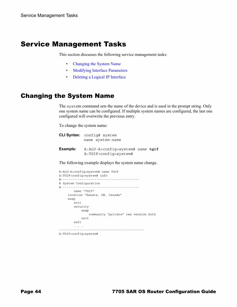
Changing the System NameThe system command sets the name of the device and is used in the prompt string. Only one system name can be configured. If multiple system names are configured, the last one configured will overwrite the previous entry.
To change the system name:
CLI Syntax: config# systemname system-name
Example: A:ALU-A>config>system# name tgifA:TGIF>config>system#
The following example displays the system name change.
A:ALU-A>config>system# name TGIFA:TGIF>config>system# info#------------------------------------------# System Configuration#------------------------------------------ name "TGIF"
location "Kanata, ON, Canada"snmp
exit security snmp community "private" rwa version both exit exit . . .----------------------------------------------A:TGIF>config>system#
Page 44 7705 SAR OS Router Configuration Guide

IP Router Configuration
Modifying Interface ParametersStarting at the config>router level, navigate down to the router interface context.
To modify an IP address, perform the following steps:
Example: A:ALU-A>config>router# interface "to-sr1"A:ALU-A>config>router>if# shutdownA:ALU-A>config>router>if# no addressA:ALU-A>config>router>if# address 10.0.0.25/24A:ALU-A>config>router>if# no shutdown
To modify a port, perform the following steps:
Example: A:ALU-A>config>router# interface "to-sr1"A:ALU-A>config>router>if# shutdownA:ALU-A>config>router>if# no port A:ALU-A>config>router>if# port 1/1/2A:ALU-A>config>router>if# no shutdown
The following example displays the interface configuration.
A:ALU-A>config>router# info#------------------------------------------# IP Configuration#------------------------------------------ interface "system" address 10.0.0.103/32 exit interface "to-sr1" address 10.0.0.25/24 port 1/1/2 exit router-id 10.10.10.104 #------------------------------------------A:ALU-A>config>router#
7705 SAR OS Router Configuration Guide Page 45

Service Management Tasks
Deleting a Logical IP InterfaceThe no form of the interface command typically removes the entry, but all entity associations must be shut down and/or deleted before an interface can be deleted.
1. Before an IP interface can be deleted, it must first be administratively disabled with the shutdown command.
2. After the interface has been shut down, it can then be deleted with the no interface command.
CLI Syntax: config>routerno interface ip-int-name
Example: config>router# interface test-interfaceconfig>router>if# shutdownconfig>router>if# exitconfig>router# no interface test-interfaceconfig>router#
Page 46 7705 SAR OS Router Configuration Guide

IP Router Configuration
IP Router Command Reference
Command Hierarchies� Configuration Commands
→ Router Commands→ Router Interface Commands
� Show Commands� Clear Commands� Debug Commands
7705 SAR OS Router Configuration Guide Page 47

IP Router Command Reference
Configuration Commands
Router Commands
config� router [router-name]
� aggregate ip-prefix/ip-prefix-length [summary-only] � no aggregate ip-prefix/ip-prefix-length� ecmp max-ecmp-routes� no ecmp� [no] allow-icmp-redirect� [no] interface ip-int-name� [no] ldp� [no] mpls� [no] ospf� [no] policy-options� router-id ip-address� no router-id� rsvp� [no] static-route {ip-prefix/prefix-length | ip-prefix netmask} [preference preference]
[metric metric] [tag tag] [enable | disable] next-hop {ip-int-name | ip-address} [bfd-enable]
� [no] static-route {ip-prefix/prefix-length | ip-prefix netmask} [preference preference] [metric metric] [tag tag] [enable | disable] black-hole
Router Interface Commands
config� router [router-name]
� [no] interface ip-int-name � address {ip-address/mask | ip-address netmask}� no address� [no] allow-directed-broadcasts� arp-timeout seconds � no arp-timeout� bfd transmit-interval [receive receive-interval] [multiplier multiplier]� no bfd� description description-string� no description� icmp
� [no] mask-reply� ttl-expired [number seconds]� no ttl-expired� unreachables [number seconds]� no unreachables
� ingress� filter ip ip-filter-id � no filter� no filter [ip ip-filter-id]
� ldp-sync-timer seconds� no ldp-sync-timer
Page 48 7705 SAR OS Router Configuration Guide

IP Router Configuration
� [no] loopback� ntp-broadcast seconds� no ntp-broadcast� port port-name� no port� qos network-policy-id� no qos� [no] shutdown� static-arp ip-addr ieee-mac-addr� no static-arp ip-addr
Show Commands
show � router router-instance
� arp [ip-int-name | ip-address/[mask] | mac ieee-mac-address | summary] [local | dynamic | static | managed]
� authentication� statistics� statistics interface [ip-int-name | ip-address]� statistics policy name
� bfd� interface� session [src ip-address [dst ip-address] | [detail]]
� ecmp� fib slot-number [family] [ip-prefix/prefix-length] [longer]� interface [{[ip-address | ip-int-name] [detail]} | [summary] | [exclude-services]� interface family [detail]]� ldp� mpls� ospf� policy� route-table [ip-prefix[/prefix-length] [longer | exact]] | [protocol protocol-name] |
[summary] � rsvp� static-arp [ip-address | ip-int-name | mac ieee-mac-addr]� static-route [family] [[ip-prefix[/mask]] | [preference preference] | [next-hop ip-address] |
[tag tag]] [detail]� status� tunnel-table [ip-address[/mask]] | [protocol protocol | sdp sdp-id] [summary]
7705 SAR OS Router Configuration Guide Page 49

IP Router Command Reference
Clear Commands
clear� router
� arp {all | ip-addr | interface {ip-int-name | ip-addr}}� authentication
� statistics [interface {ip-int-name | ip-address}]� bfd
� session src-ip ip-address dst-ip ip-address� session all� statistics src-ip ip-address dst-ip ip-address� statistics all
� interface [ip-int-name | ip-addr] [icmp]� ldp� mpls� ospf
Debug Commands
debug� trace
� destination trace-destination� [no] enable� [no] trace-point [module module-name] [type event-type] [class event-class] [task
task-name] [function function-name]� router router-instance
� [no] ip� [no] arp� icmp� no icmp� [no] interface [ip-int-name | ip-address]� [no] neighbor� packet [ip-int-name | ip-address] [headers] [protocol-id]� no packet [ip-int-name | ip-address]� route-table [ip-prefix/prefix-length] [longer]� no route-table
� [no] ldp� [no] mpls� [no] ospf� [no] rsvp
Note: For information on MPLS, LDP, and RSVP, see the 7705 SAR OS MPLS Guide. For information on OSPF, see the 7705 SAR OS Routing Protocols Guide. For information on policy options, see Route Policies on page 149.
Page 50 7705 SAR OS Router Configuration Guide

IP Router Configuration
Command Descriptions� Configuration Commands on page 52� Show Commands on page 70� Clear Commands on page 89� Debug Commands on page 91
7705 SAR OS Router Configuration Guide Page 51
IP Router Command Reference
Configuration Commands
� Generic Commands on page 53� Router Global Commands on page 54� Router Interface Commands on page 59� Router Interface Filter Commands on page 67� Router Interface ICMP Commands on page 68
Page 52 7705 SAR OS Router Configuration Guide

IP Router Configuration
Generic Commands
description
Syntax description description-stringno description
Context config>router>interface ip-int-name
Description This command creates a text description stored in the configuration file for a configuration context.
The no form of the command removes the description string from the context.
Default no description
Parameters description-string � the description character string. Allowed values are any string up to 80 characters long composed of printable, 7-bit ASCII characters. If the string contains special characters (#, $, spaces, etc.), the entire string must be enclosed within double quotes.
shutdown
Syntax shutdownno shutdown
Context config>router>interface ip-int-name
Description The shutdown command administratively disables the entity. The operational state of the entity is disabled as well as the operational state of any entities contained within. When disabled, an entity does not change, reset, or remove any configuration settings or statistics. Many objects must be shut down before they may be deleted. Many entities must be explicitly enabled using the no shutdown command.
Unlike other commands and parameters where the default state is not indicated in the configuration file, shutdown and no shutdown are always indicated in system-generated configuration files.
The no form of the command puts an entity into the administratively enabled state.
Default no shutdown
7705 SAR OS Router Configuration Guide Page 53

IP Router Command Reference
Router Global Commands
router
Syntax router router-name
Context config
Description This command enables the context to configure router parameters, interfaces, route policies, and protocols.
Parameters router-name � the router name
Values router-name: Base, management
Default Base
aggregate
Syntax aggregate ip-prefix/ip-prefix-length [summary-only] no aggregate ip-prefix/ip-prefix-length
Context config>router
Description This command creates an aggregate route.
Use this command to group a number of routes with common prefixes into a single entry in the routing table. This reduces the number of routes that need to be advertised by this router and reduces the number of routes in the routing tables of downstream routers.
Both the original components and the aggregated route (source protocol aggregate) are offered to the Routing Table Manager (RTM). Subsequent policies can be configured to assign protocol-specific characteristics, such as the OSPF tag, to aggregate routes.
Multiple entries with the same prefix but a different mask can be configured; routes are aggregated to the longest mask. If one aggregate is configured as 10.0/16 and another as 10.0.0/24, then route 10.0.128/17 would be aggregated into 10.0/16, and route 10.0.0.128/25 would be aggregated into 10.0.0/24. If multiple entries are made with the same prefix and the same mask, the previous entry is overwritten.
The no form of the command removes the aggregate.
Default no aggregate
Page 54 7705 SAR OS Router Configuration Guide

IP Router Configuration
Parameters ip-prefix/length � the destination address of the aggregate route in dotted-decimal notation
Values ip-prefix a.b.c.d (host bits must be 0)ip-prefix-length 0 to 32
summary-only � suppresses advertisement of more specific component routes for the aggregate
To remove the summary-only option, enter the same aggregate command without the summary-only parameter.
ecmp
Syntax ecmp max-ecmp-routesno ecmp
Context config>router
Description This command enables ECMP and configures the number of routes for path sharing; for example, the value 2 means two equal-cost routes will be used for cost sharing.
ECMP (Equal-Cost Multipath Protocol) refers to the distribution of packets over two or more outgoing links that share the same routing cost. ECMP provides a fast local reaction to route failures. ECMP is supported on static routes and dynamic (OSPF) routes.
As an example, ECMP for LDP can be used to distribute MPLS traffic across the links in order to balance the traffic load. If ECMP for LDP is enabled and there is more than one pseudowire service configured, load balancing will take place on a per-pseudowire basis. ECMP for LDP will load-balance traffic across all equal-cost links on a per-service basis.
ECMP is also used to balance IP traffic. If multiple routes are learned with an identical preference using the same protocol, the lowest-cost route is used. If multiple routes are learned with an identical preference using the same protocol and the costs (metrics) are equal, the decision of what route to use is determined by the configuration of ECMP.
ECMP can only be used for routes with the same preference and same protocol. See the static-route command for information on preferences.
When more ECMP routes are available at the best preference than configured in max-ecmp-routes, then the lowest next-hop IP address algorithm is used to select the number of routes configured in max-ecmp-routes.
The no form of the command disables ECMP path sharing. If ECMP is disabled and multiple routes are available at the best preference and equal cost, the route with the lowest next-hop IP address is used.
The no form of the command disables ECMP path sharing.
Default no ecmp
7705 SAR OS Router Configuration Guide Page 55

IP Router Command Reference
Parameters max-ecmp-routes � the maximum number of equal cost routes allowed on this routing table instance, expressed as a decimal integer. Setting ECMP max-ecmp-routes to 1 yields the same result as entering no ecmp.
Values 0 to 8
allow-icmp-redirect
Syntax [no] allow-icmp-redirect
Context config>router
Description This command allows or drops ICMP redirects received on the management interface.
router-id
Syntax router-id ip-addressno router-id
Context config>router
Description This command configures the router ID for the router instance.
The router ID is used by OSPF in the routing table manager. Refer to the 7705 SAR OS Routing Protocols Guide for information on OSPF.
When configuring a new router ID, protocols are not automatically restarted with the new router ID. The next time a protocol is initialized, the new router ID is used. This can result in an interim period when different protocols use different router IDs.
To force the new router ID to be used, issue the shutdown and no shutdown commands for each protocol that uses the router ID, or restart the entire router.
The no form of the command to reverts to the default value.
Default The system uses the system interface address (which is also the loopback address). If a system interface address is not configured, the last 4 bytes of the MAC address are used.
Parameters ip-address � the 32-bit router ID expressed in dotted-decimal notation
Page 56 7705 SAR OS Router Configuration Guide

IP Router Configuration
static-route
Syntax [no] static-route {ip-prefix/prefix-length | ip-prefix netmask} [preference preference] [metric metric] [tag tag] [enable | disable] next-hop {ip-int-name | ip-address} [bfd-enable][no] static-route {ip-prefix/prefix-length | ip-prefix netmask} [preference preference] [metric metric] [tag tag] [enable | disable] black-hole
Context config>router
Description This command creates static route entries for network routes. When configuring a static route, the next-hop or black-hole must be configured.
The no form of the command deletes the static route entry. If a static route needs to be removed when multiple static routes exist to the same destination, as many parameters as necessary to uniquely identify the static route must be entered.
Default no static-route
Parameters ip-prefix/prefix-length � the destination address of the static route
Values ip-prefix a.b.c.d (host bits must be 0)ip-prefix-length 0 to 32
netmask � the subnet mask in dotted-decimal notation
Values 0.0.0.0 to 255.255.255.255 (network bits all 1 and host bits all 0)
preference � the preference of this static route versus the routes from different sources such as OSPF, expressed as a decimal integer. When modifing the preference of an existing static route, the metric will not be changed unless specified.
Different protocols should not be configured with the same preference. If this occurs, the tiebreaker is according to the default preference table defined in Table 3.
If multiple routes are learned with an identical preference using the same protocol, the lowest- cost route is used. If multiple routes are learned with an identical preference using the same protocol, and the costs (metrics) are equal, the route to use is determined by the configuration of the ecmp command.
Default 5
Values 1 to 255
Table 3: Route Preference Defaults by Route Type
Route Type Preference ConfigurableDirect attached 0 No
Static routes 5 Yes
OSPF internal 10 Yes
OSPF external 150 Yes
7705 SAR OS Router Configuration Guide Page 57

IP Router Command Reference
metric � the cost metric for the static route, expressed as a decimal integer. This value is used when importing the static route into other protocols such as OSPF. When the metric is configured as 0, then the metric configured in OSPF applies.
This value is also used to determine which static route to install in the forwarding table.
� If there are multiple static routes with unequal metrics, the lower-cost (metric) route will be installed.
� If there are multiple static routes with equal metrics, ECMP rules apply.
Default 1
Values 0 to 65535
tag � adds a 32-bit integer tag to the static route. The tag is used in route policies to control distribution of the route into other protocols.
Values 1 to 4294967295
enable � static routes can be administratively enabled or disabled. Use the enable parameter to re-enable a disabled static route. In order to enable a static route, it must be uniquely identified by the IP address, mask, and any other parameter that is required to identify the exact static route.
The administrative state is maintained in the configuration file.
Default enable
disable � static routes can be administratively enabled or disabled. Use the disable parameter to disable a static route while maintaining the static route in the configuration. In order to enable a static route, it must be uniquely identified by the IP address, mask, and any other parameter that is required to identify the exact static route.
The administrative state is maintained in the configuration file.
Default enable
[ip-int-name | ip-address] � specifies the directly connected next hop IP address used to reach the destination. If the next hop is over an unnumbered interface, the ip-int-name of the unnumbered interface (on this node) can be configured.
The ip-address configured here must be on the network side on this node. This address must be associated with a network that is directly connected to a network configured on this node.
Values ip-int-name 32 chars max ip-address a.b.c.d
bfd-enable � associates the state of the static route to a BFD session between the local system and the configured next hop
blackhole � specifies that the route is a blackhole route. If the destination address on a packet matches this static route, it will be silently discarded.
The black-hole keyword and the next-hop keyword are mutually exclusive. If an identical command is entered (with the exception of the next-hop parameters), this static route will be replaced with the newly entered configured route, and unless specified, the respective defaults for preference and metric will be applied.
Page 58 7705 SAR OS Router Configuration Guide
IP Router Configuration
Router Interface Commands
interface
Syntax [no] interface ip-int-name
Context config>router
Description This command creates a logical IP routing interface. When created, attributes like IP address, port, or system can be associated with the IP interface.
Interface names are case-sensitive and must be unique within the group of IP interfaces defined for config router interface. Interface names must not be in the dotted-decimal notation of an IP address and must begin with a letter; for example, the name �1.1.1.1� is not allowed, but �int-1.1.1.1� is allowed.
Show commands for router interfaces use either the interface names or the IP addresses. Ambiguity can exist if an IP address is used both as an IP address and an interface name. Duplicate interface names can exist in different router instances, although this is not recommended because it is confusing.
When a new name is entered, a new logical router interface is created. When an existing interface name is entered, the user enters the router interface context for editing and configuration.
Although not a keyword, the interface name �system� is associated with the network entity (such as a specific 7705 SAR), not a specific interface. The system interface is also referred to as the loopback address.
The no form of the command removes the IP interface and all the associated configurations. The interface must be administratively shut down before issuing the no interface command.
Default no interface
Parameters ip-int-name � the name of the IP interface. Interface names must be unique within the group of defined IP interfaces for config router interface commands. An interface name cannot be in the form of an IP address. If the string contains special characters (#, $, spaces, etc.), the entire string must be enclosed within double quotes.
Values 1 to 32 alphanumeric characters (must start with a letter)
If the ip-int-name already exists, the context is changed to maintain that IP interface. If the ip-int-name already exists as an IP interface defined within the config router commands, an error will occur and the context will not be changed to that IP interface. If the ip-int-name does not exist, the interface is created and the context is changed to that interface for further command processing.
7705 SAR OS Router Configuration Guide Page 59
IP Router Command Reference
address
Syntax address {ip-address/mask | ip-address netmask}no address
Context config>router>interface ip-int-name
Description This command assigns an IP address and IP subnet to an IP interface. Only one IP address can be associated with an IP interface.
An IP address must be assigned to each IP interface. An IP address and a mask combine to create a local IP prefix. The defined IP prefix must be unique within the context of the routing instance. It cannot overlap with other existing IP prefixes defined as local subnets on other IP interfaces in the same routing context within the router.
The IP address for the interface can be entered in either CIDR (Classless Inter-Domain Routing) or traditional dotted-decimal notation. Show commands display CIDR notation and are stored in configuration files.
By default, no IP address or subnet association exists on an IP interface until it is explicitly created.
The no form of the command removes the IP address assignment from the IP interface. The no form of this command can only be performed when the IP interface is administratively shut down. Shutting down the IP interface will operationally stop any MPLS LSPs that explicitly reference that IP address. When a new IP address is defined, the IP interface can be administratively enabled (no shutdown), which reinitializes the MPLS LSPs associated with that IP interface.
To change an IP address, perform the following steps:
1. Shut down the router interface.2. Assign the new IP address.3. Enable the router interface.
If a new address is entered while another address is still active, the new address will be rejected.
Default no address
Parameters ip-address � the IP address of the IP interface. The ip-address portion of the address command specifies the IP host address that will be used by the IP interface within the subnet. This address must be unique within the subnet and specified in dotted-decimal notation.
Values 1.0.0.0 to 223.255.255.255
/ � the forward slash is a parameter delimiter that separates the ip-address portion of the IP address from the mask that defines the scope of the local subnet. No spaces are allowed between the ip-address, the �/� and the mask parameter. If a forward slash does not immediately follow the ip-address, a dotted-decimal mask must follow the prefix.
Page 60 7705 SAR OS Router Configuration Guide

IP Router Configuration
mask � the subnet mask length when the IP prefix is specified in CIDR notation. When the IP prefix is specified in CIDR notation, a forward slash (/) separates the ip-address from the mask parameter. The mask parameter indicates the number of bits used for the network portion of the IP address; the remainder of the IP address is used to determine the host portion of the IP address.
Values 1 to 32 (mask length of 32 is reserved for system IP addresses)
netmask � the subnet mask in dotted-decimal notation
Values 0.0.0.0 to 255.255.255.255 (network bits all 1 and host bits all 0)
allow-directed-broadcasts
Syntax [no] allow-directed-broadcasts
Context config>router>interface ip-int-name
Description This command enables the forwarding of directed broadcasts out of the IP interface.
A directed broadcast is a packet received on a local router interface destined for the subnet broadcast address of another IP interface. The allow-directed-broadcasts command on an IP interface enables or disables the transmission of packets destined for the subnet broadcast address of the egress IP interface.
When enabled, a frame destined to the local subnet on this IP interface is sent as a subnet broadcast out this interface. Note: Allowing directed broadcasts is a well-known mechanism used for denial-of-service attacks.
By default, directed broadcasts are not allowed and are discarded at this egress IP interface.
The no form of the command disables directed broadcasts forwarding out of the IP interface.
Default no allow-directed broadcasts
7705 SAR OS Router Configuration Guide Page 61
IP Router Command Reference
arp-timeout
Syntax arp-timeout secondsno arp-timeout
Context config>router>interface ip-int-name
Description This command configures the minimum time, in seconds, that an ARP entry learned on the IP interface is stored in the ARP table. ARP entries are automatically refreshed when an ARP request or gratuitous ARP is seen from an IP host. Otherwise, the ARP entry is aged from the ARP table. If the arp-timeout value is set to 0 seconds, ARP aging is disabled.
The no form of the command reverts to the default value.
Default no arp-timeout
Parameters seconds � the minimum number of seconds a learned ARP entry is stored in the ARP table, expressed as a decimal integer. A value of 0 specifies that the timer is inoperative and learned ARP entries will not be aged.
Values 0 to 65535
Default 14400 seconds (4 hours)
bfd
Syntax bfd {transmit-interval} [receive receive-interval] [multiplier multiplier]no bfd
Context config>router>interface ip-int-name
Description This command configures the time interval in which BFD control messages are transmitted and received on the interface and the number of control messages to be transmitted and received within that interval. This mechanism is used to detect failures in the network. If either end does not receive the specified number of messages in the specified time interval, the far end is declared to be down.
Default no bfd
Parameters transmit-interval � the number of milliseconds between transmitted control messages
Values 100 to 100000
Default 100
receive-interval � the number of millseconds between received control messages
Values 100 to 100000
Default 100
Note: The 7705 SAR will attempt to refresh an ARP entry 30 s prior to its expiry. This refresh attempt occurs only if the ARP timeout is set to 45 s or more.
Page 62 7705 SAR OS Router Configuration Guide

IP Router Configuration
multiplier � the number of control messages to be sent during the configured transmit and receive intervals
Values 3 to 20
Default 3
ntp-broadcast
Syntax ntp-broadcastno ntp-broadcast
Context config>router>interface ip-int-name
Description This command enables or disables the receiving of SNTP broadcasts on the IP interface.
This parameter is only valid when the SNTP broadcast-client global parameter is configured.
The no form of the command disables SNTP broadcast received on the IP interface.
Default no ntp-broadcast
ldp-sync-timer
Syntax ldp-sync-timer secondsno ldp-sync-timer
Context config>router>interface ip-int-name
Description This command configures the IGP-LDP synchronization timer to enable synchronization of IGP and LDP. When a link is restored after a failure, IGP sets the link cost to infinity and advertises it. In Release 2.0, the supported IGP is OSPF. The actual value advertised in OSPF is 0xFFFF (65535).
After IGP advertises the link cost, the LDP hello adjacency is brought up with the neighbor. The LDP synchronization timer is started by IGP from the time the LDP session to the neighbor is up over the interface. This is to allow time for the label-FEC bindings to be exchanged.
When the LDP synchronization timer expires, the link cost is restored and is readvertised. IGP will announce a new best next-hop and LDP will use it if the label binding for the neighbor�s FEC is available.
If the user changes the cost of an interface, the new value is advertised at the next flooding of link attributes by IGP. However, if the LDP synchronization timer is still running, the new cost value will only be advertised after the timer expires. Also, the new cost value will be advertised after the user executes any of the following commands if the currently advertised cost is different:
� tools>perform>router>ospf>ldp-sync-exit
� config>router>interface>no ldp-sync-timer
� config>router>ospf>disable-ldp-sync
7705 SAR OS Router Configuration Guide Page 63

IP Router Command Reference
Refer to the 7705 SAR OS Services Guide for the tools commands and to the 7705 SAR OS Routing Protocols Guide for the OSPF commands.
If the user changes the value of the LDP synchronization timer parameter, the new value will take effect at the next synchronization event. In other words, if the timer is still running, it will continue using the previous value.
If parallel links exist to the same neighbor, the bindings and services should remain up as long as there is one interface that is up. However, the user-configured LDP synchronization timer still applies on the failed then restored interface. In this case, the 7705 SAR will only consider this interface for forwarding after IGP readvertises its actual cost value.
The LDP Sync Timer State is not always synched across to the standby CSM; therefore, after an activity switch, the timer state might not be same as it was on the previously active CSM.
The no form of this command disables IGP-LDP synchronization and deletes the configuration.
Default no ldp-sync-timer
Parameters seconds � the time interval for the IGP-LDP synchronization timer
Values 1 to 800
loopback
Syntax [no] loopback
Context config>router>interface ip-int-name
Description This command configures the interface as a loopback interface.
Default no loopback
port
Syntax port port-nameno port
Context config>router>interface ip-int-name
Description This command creates an association with a logical IP interface and a physical port.
An interface can also be associated with the system (loopback address).
The command returns an error if the interface is already associated with another port or the system. In this case, the association must be deleted before the command is reattempted.
The port name consists of the port-id (for T1/E1 interfaces and Ethernet interfaces) and an optional encapsulation value (for Ethernet interfaces). The port name can also be the bundle-id used for the multilink bundle associated with the interface. See the 7705 SAR OS Interface Configuration Guide for information on configuring ports.
Page 64 7705 SAR OS Router Configuration Guide

IP Router Configuration
The no form of the command deletes the association with the port. The no form of this command can only be performed when the interface is administratively down.
Default no port
Parameters port-name � the physical port identifier to associate with the IP interface
Values port-id slot/mda/port
bundle-id bundle-type-slot/mda.bundle-numbundle keywordtype ima, pppbundle-num 1 to 128
encap-val 0 (for null)0 to 4094 (for dot1q)
qos
Syntax qos network-policy-idno qos
Context config>router>interface ip-int-name
Description This command associates a network Quality of Service (QoS) policy with an IP interface.
Only one network QoS policy can be associated with an IP interface at one time. Attempts to associate a second QoS policy return an error.
Packets are marked using QoS policies on edge devices. Invoking a QoS policy on a network port allows for the packets that match the policy criteria to be remarked.
The no form of the command removes the QoS policy association from the IP interface, and the QoS policy reverts to the default.
Default qos 1 � IP interface associated with network QoS policy 1
Parameters network-policy-id � the network policy ID to associate with the IP interface. The policy ID must already exist.
Values 1 to 65535
7705 SAR OS Router Configuration Guide Page 65
IP Router Command Reference
static-arp
Syntax static-arp ip-addr ieee-mac-addrno static-arp ip-addr
Context config>router>interface
Description This command configures a static ARP entry associating an IP address with a MAC address for the core router instance. This static ARP appears in the core routing ARP table. A static ARP can only be configured if it exists on the network attached to the IP interface.
If an entry for a particular IP address already exists and a new MAC address is configured for the IP address, the existing MAC address is replaced by the new MAC address.A router interface can only have one static ARP entry configured for it. The number of static-arp entries that can be configured on a single node is limited to 8.
Static ARP is used when a 7705 SAR needs to know about a device on an interface that cannot or does not respond to ARP requests. Thus, the 7705 SAR OS configuration can state that if it has a packet that has a certain IP address to send it to the corresponding ARP address.
The no form of the command removes a static ARP entry.
Default no static-arp
Parameters ip-addr � the IP address for the static ARP in IP address dotted-decimal notation
ieee-mac-addr � the 48-bit MAC address for the static ARP in the form aa:bb:cc:dd:ee:ff or aa-bb-cc-dd-ee-ff, where aa, bb, cc, dd, ee and ff are hexadecimal numbers. Allowed values are any non-broadcast, non-multicast MAC and non-IEEE reserved MAC addresses.
Page 66 7705 SAR OS Router Configuration Guide

IP Router Configuration
Router Interface Filter Commands
ingress
Syntax ingress
Context config>router>interface ip-int-name
Description This command enables access to the context to configure ingress network filter policies for the IP interface.
If an ingress filter is not defined, no filtering is performed.
filter
Syntax filter ip ip-filter-idno filterno filter [ip ip-filter-id]
Context config>router>if>ingress
Description This command associates an IP filter policy with an IP interface.
Filter policies control packet forwarding and dropping based on IP match criteria.
The ip-filter-id must have been pre-configured before this filter command is executed. If the filter ID does not exist, an error occurs.
Only one filter ID can be specified.
The no form of the command removes the filter policy associated with the IP interface.
Default No filter is specified.
Parameters ip-filter-id � the filter name acts as the ID for the IP filter policy expressed as a decimal integer. The filter policy must already exist within the config>filter>ip-filter context.
Values 1 to 65535
Note: For information on configuring IP filter IDs, see Creating an IP Filter Policy on page 107.
7705 SAR OS Router Configuration Guide Page 67

IP Router Command Reference
Router Interface ICMP Commands
icmp
Syntax icmp
Context config>router>interface ip-int-name
Description This command enables access to the context to configure Internet Control Message Protocol (ICMP) parameters on a network IP interface. ICMP is a message control and error reporting protocol that also provides information relevant to IP packet processing.
mask-reply
Syntax mask-replyno mask-replay
Context config>router>if>icmp
Description This command enables or disables responses to ICMP mask requests on the router interface.
If a local node sends an ICMP mask request to the router interface, the mask-reply command configures the router interface to reply to the request.
The no form of the command disables replies to ICMP mask requests on the router interface.
Default mask-reply � replies to ICMP mask requests
ttl-expired
Syntax ttl-expired [number seconds]no ttl-expired
Context config>router>if>icmp
Description This command configures the rate that ICMP Time To Live (TTL) expired messages are issued by the IP interface.
By default, generation of ICMP TTL expired messages is enabled at a maximum rate of 100 per 10-second time interval.
The no form of the command disables the generation of TTL expired messages.
Default ttl-expired 100 10 � maximum of 100 TTL expired message in 10 seconds
Page 68 7705 SAR OS Router Configuration Guide
IP Router Configuration
Parameters number � the maximum number of ICMP TTL expired messages to send, expressed as a decimal integer. The seconds parameter must also be specified.
Values 10 to 100
seconds � the time frame, in seconds, used to limit the number of ICMP TTL expired messages that can be issued, expressed as a decimal integer
Values 1 to 60
unreachables
Syntax unreachables [number seconds]no unreachables
Context config>router>if>icmp
Description This command enables and configures the rate for ICMP host and network destination unreachable messages issued on the router interface.
The unreachables command enables the generation of ICMP destination unreachables on the router interface. The rate at which ICMP unreachables is issued can be controlled with the optional number and seconds parameters by indicating the maximum number of destination unreachable messages that can be issued on the interface for a given time interval.
By default, generation of ICMP destination unreachables messages is enabled at a maximum rate of 100 per 10-second time interval.
The no form of the command disables the generation of ICMP destination unreachables on the router interface.
Default unreachables 100 10 � maximum of 100 unreachable messages in 10 seconds
Parameters number � the maximum number of ICMP unreachable messages to send, expressed as a decimal integer. The seconds parameter must also be specified.
Values 10 to 100
seconds � the time frame, in seconds, used to limit the number of ICMP unreachable messages that can be issued, expressed as a decimal integer
Values 1 to 60
7705 SAR OS Router Configuration Guide Page 69

IP Router Command Reference
Show Commands
arp
Syntax arp [ip-int-name | ip-address/[mask] | mac ieee-mac-address | summary] [arp-type]
Context show>router
Description This command displays the router ARP table sorted by IP address.
If no command line options are specified, all ARP entries are displayed.
Parameters ip-int-name � only displays the ARP entry associated with the specified IP interface name
ip-address/[mask] � only displays the ARP entry associated with the specified IP address and optional mask
ieee-mac-addr � only displays the ARP entry associated with the specified MAC address
summary � displays an abbreviated list of ARP entries
arp-type � only displays ARP information associated with the specified keyword
Output ARP Table Output � The following table describes the ARP table output fields.
Note: Multiple MAC addresses can be associated with an interface that is a network port.
Table 4: Show ARP Table Output Fields
Label Description
IP Address The IP address of the ARP entry
MAC Address The MAC address of the ARP entry
Expiry The age of the ARP entry
Type Dyn — the ARP entry is a dynamic ARP entry
Inv — the ARP entry is an inactive static ARP entry (invalid)
Oth — the ARP entry is a local or system ARP entry
Sta — the ARP entry is an active static ARP entry
Interface The IP interface name associated with the ARP entry
No. of ARP Entries
The number of ARP entries displayed in the list
Page 70 7705 SAR OS Router Configuration Guide

IP Router Configuration
Sample Output
A:ALU-A# show router arp===============================================================================ARP Table ===============================================================================IP Address MAC Address Expiry Type Interface -------------------------------------------------------------------------------10.10.0.3 04:5d:ff:00:00:00 00:00:00 Oth system 10.10.13.1 04:5b:01:01:00:02 03:53:09 Sta to-ser1 10.10.13.3 04:5d:01:01:00:02 00:00:00 Oth to-ser1 10.10.34.3 04:5d:01:01:00:01 00:00:00 Oth to-ser4 10.10.34.4 04:5e:01:01:00:01 01:08:00 Sta to-ser4 10.10.35.3 04:5d:01:01:00:03 00:00:00 Oth to-ser5 10.10.35.5 04:5f:01:01:00:03 02:47:07 Sta to-ser5 192.168.2.93 00:03:47:97:68:7d 00:00:00 Oth management -------------------------------------------------------------------------------No. of ARP Entries: 8 ===============================================================================A:ALU-A#
A:ALU-A# show router arp 10.10.0.3===============================================================================ARP Table ===============================================================================IP Address MAC Address Expiry Type Interface -------------------------------------------------------------------------------10.10.0.3 04:5d:ff:00:00:00 00:00:00 Oth system ===============================================================================A:ALU-A#
A:ALU-A# show router arp to-ser1===============================================================================ARP Table ===============================================================================IP Address MAC Address Expiry Type Interface ------------------------------------------------------------------------------- 10.10.13.1 04:5b:01:01:00:02 03:53:09 Sta to-ser1 ===============================================================================A:ALU-A#
7705 SAR OS Router Configuration Guide Page 71

IP Router Command Reference
authentication
Syntax authentication statisticsauthentication statistics interface [ip-int-name | ip-address]authentication statistics policy name
Context show>router>authentication
Description This command displays interface or policy authentication statistics.
Parameters [ip-int-name | ip-address] � specifies an existing interface name or IP address
Values ip-int-name 32 chars maxip-address a.b.c.d
name � specifies an existing policy name
Output Authentication Statistics Output � The following table describes the authentication statistics output fields.
Sample Output
*A:ALU-1#show>router>auth# statistics
===================================================================Authentication Global Statistics===================================================================Client Packets Authenticate Fail : 0 Client Packets Authenticate Ok : 12 ===================================================================*A:ALU-1#
Table 5: Show Authentication Statistics Output Fields
Label Description
Client Packets Authenticate Fail
The number of packets that failed authentication
Client Packets Authenticate Ok
The number of packets that were authenticated
Page 72 7705 SAR OS Router Configuration Guide
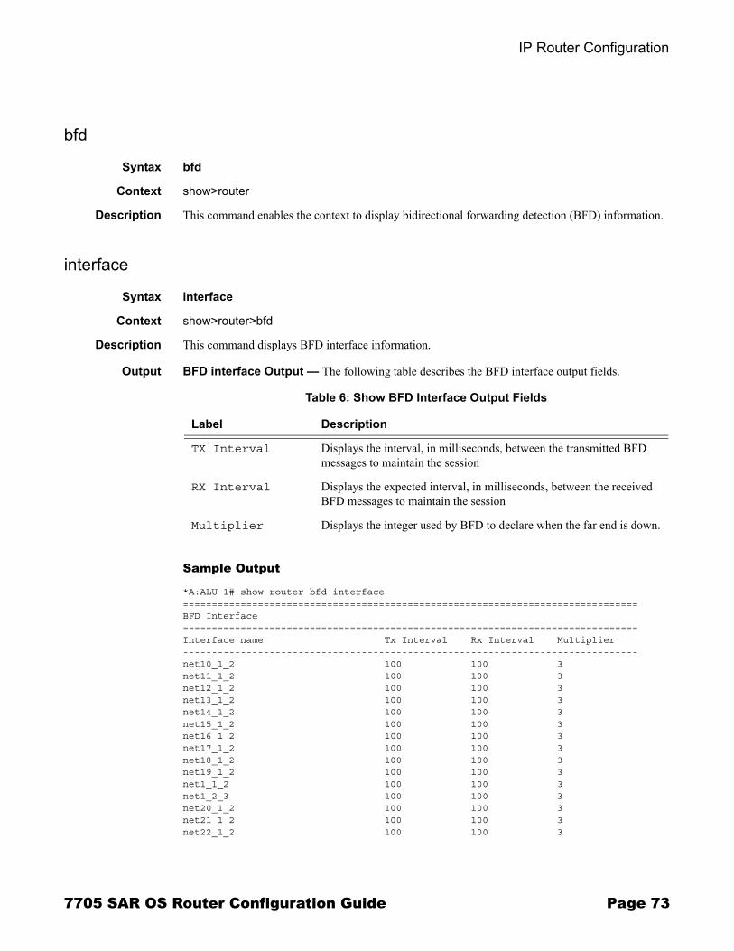
IP Router Configuration
bfd
Syntax bfd
Context show>router
Description This command enables the context to display bidirectional forwarding detection (BFD) information.
interface
Syntax interface
Context show>router>bfd
Description This command displays BFD interface information.
Output BFD interface Output � The following table describes the BFD interface output fields.
Sample Output
*A:ALU-1# show router bfd interface===============================================================================BFD Interface===============================================================================Interface name Tx Interval Rx Interval Multiplier -------------------------------------------------------------------------------net10_1_2 100 100 3 net11_1_2 100 100 3 net12_1_2 100 100 3 net13_1_2 100 100 3 net14_1_2 100 100 3 net15_1_2 100 100 3 net16_1_2 100 100 3 net17_1_2 100 100 3 net18_1_2 100 100 3 net19_1_2 100 100 3 net1_1_2 100 100 3 net1_2_3 100 100 3 net20_1_2 100 100 3 net21_1_2 100 100 3 net22_1_2 100 100 3
Table 6: Show BFD Interface Output Fields
Label Description
TX Interval Displays the interval, in milliseconds, between the transmitted BFD messages to maintain the session
RX Interval Displays the expected interval, in milliseconds, between the received BFD messages to maintain the session
Multiplier Displays the integer used by BFD to declare when the far end is down.
7705 SAR OS Router Configuration Guide Page 73

IP Router Command Reference
net23_1_2 100 100 3 net24_1_2 100 100 3 net25_1_2 100 100 3 net2_1_2 100 100 3 net3_1_2 100 100 3 net4_1_2 100 100 3 net5_1_2 100 100 3 net6_1_2 100 100 3 net7_1_2 100 100 3 net8_1_2 100 100 3 net9_1_2 100 100 3 -------------------------------------------------------------------------------No. of BFD Interfaces: 26===============================================================================
session
Syntax session [src ip-address [dst ip-address | detail]]
Context show>router>bfd
Description This command displays session information.
Parameters ip-address � displays the interface information associated with the specified IP address
Values a.b.c.d (host bits must be 0)
Output BFD Session Output � The following table describes the BFD session output fields.
Table 7: Show BFD Session Output Fields
Label Description
State Displays the administrative state for this BFD session
Protocol Displays the active protocol
Tx Intvl Displays the interval, in milliseconds, between the transmitted BFD messages to maintain the session
Tx Pkts Displays the number of transmitted BFD packets
Rx Intvl Displays the expected interval, in milliseconds, between the received BFD messages to maintain the session
Rx Pkts Displays the number of received packets
Mult Displays the integer used by BFD to declare when the neighbor is down
Page 74 7705 SAR OS Router Configuration Guide

IP Router Configuration
Sample Output
*A:ALU-1# show router bfd session===============================================================================BFD Session===============================================================================Interface State Tx Intvl Rx Intvl Mult Remote Address Protocol Tx Pkts Rx Pkts -------------------------------------------------------------------------------net1_1_2 Up (3) 100 100 3 12.1.2.1 None 5029 5029 net1_2_3 Up (3) 100 100 3 12.2.3.2 None 156367 156365 -------------------------------------------------------------------------------No. of BFD sessions: 2===============================================================================*A:ALU-1#
ecmp
Syntax ecmp
Context show>router
Description This command displays the ECMP settings for the router.
Output ECMP Settings Output � The following table describes the output fields for the router ECMP settings.
Sample Output
A:ALU-A# show router ecmp===============================================================================Router ECMP ===============================================================================Instance Router Name ECMP Configured-ECMP-Routes -------------------------------------------------------------------------------1 Base True 8 ===============================================================================
Table 8: Show ECMP Settings Output Fields
Label Description
Instance The router instance number
Router Name The name of the router instance
ECMP False — ECMP is disabled for the instance
True — ECMP is enabled for the instance
Configured-ECMP-Routes
The number of ECMP routes configured for path sharing
7705 SAR OS Router Configuration Guide Page 75

IP Router Command Reference
fib
Syntax fib slot-number [family] [ip-prefix/prefix-length] [longer]
Context show>router
Description This command displays the active FIB entries for a specific CSM.
Parameters slot-number � displays only the routes matching the specified chassis slot number
Values 1
family � displays the specified router IP interface table
Values ipv4 � displays only those peers that have the IPv4 family enabled
ip-prefix/prefix-length � displays FIB entries only matching the specified ip-prefix and prefix-length
Values ip-prefix a.b.c.d (host bits must be 0)ip-prefix-length 0 to 32
longer � displays FIB entries matching the ip-prefix/prefix-length and routes with longer masks
interface
Syntax interface [{[ip-address | ip-int-name] [detail]} | [summary] | [exclude-services]interface family [detail]]
Context show>router
Description This command displays the router IP interface table sorted by interface index.
Parameters ip-address � only displays the interface information associated with the specified IP address
Values ip-address a.b.c.d (host bits must be 0)
ip-int-name � only displays the interface information associated with the specified IP interface
detail � displays detailed IP interface information
summary � displays summary IP interface information for the router
exclude-services � displays IP interface information, excluding IP interfaces configured for customer services. Only core network IP interfaces are displayed.
family � displays the specified router IP interface family
Values ipv4 � displays only those peers that have the IPv4 family enabled
Page 76 7705 SAR OS Router Configuration Guide

IP Router Configuration
Output Standard IP Interface Output � The following table describes the standard output fields for an IP interface.
Sample Output
*A:ALU-1# show router interface
===============================================================================Interface Table (Router: Base)===============================================================================Interface-Name Adm Opr Mode Port/SapId IP-Address PfxState-------------------------------------------------------------------------------ip-100.0.0.2 Up Down Network 1/1/1 100.10.0.2/10 n/asystem Up Down Network system - -to-103 Up Down Network n/a - --------------------------------------------------------------------------------Interfaces : 3===============================================================================*A:ALU-1#
*A:ALU-1# show router interface to-103
===============================================================================Interface Table (Router: Base)===============================================================================Interface-Name Adm Opr Mode Port/SapId IP-Address PfxState-------------------------------------------------------------------------------to-103 Up Down Network n/a - --------------------------------------------------------------------------------
Table 9: Show Standard IP Interface Output Fields
Label Description
Interface-Name The IP interface name
IP-Address The IP address and subnet mask length of the IP interfacen/a — no IP address has been assigned to the IP interface
Adm Down — the IP interface is administratively disabled
Up — the IP interface is administratively enabled
Opr Down — the IP interface is operationally disabled
Up — the IP interface is operationally enabled
Mode Network — the IP interface is a network/core IP interface
Port/SapId The port or SAP that the interface is bound to
7705 SAR OS Router Configuration Guide Page 77

IP Router Command Reference
Detailed IP Interface Output � The following table describes the detailed output fields for an IP interface.
Table 10: Show Detailed IP Interface Output Fields
Label Description
If Name The IP interface name
Admin State Down — the IP interface is administratively disabled
Up — the IP interface is administratively enabled
Oper State Down — the IP interface is operationally disabled
Up — the IP interface is operationally enabled
IP Addr/mask The IP address and subnet mask length of the IP interface n/a — no IP address has been assigned to the IP interface
Address Type For Release 2.0, this is always Primary
If Index The interface index of the IP router interface
Virt If Index The virtual interface index of the IP router interface
Last Oper Chg The last change in operational status
Global If Index The global interface index of the IP router interface
Port ID The port identifier
TOS Marking The TOS byte value in the logged packet
If Type Network — the IP interface is a network/core IP interface
Egress FilterIngress Filter
Indicates whether filters are applied to the port. For Release 2.0, filters are applied to ingress network ports only.
QoS Policy The QoS policy ID associated with the IP interface
MAC Address The MAC address of the IP interface
Arp Timeout The ARP timeout for the interface, in seconds, which is the time an ARP entry is maintained in the ARP cache without being refreshed
IP MTU The IP Maximum Transmission Unit (MTU) for the IP interface
ICMP Mask Reply False — the IP interface will not reply to a received ICMP mask request
True — the IP interface will reply to a received ICMP mask request
Arp Populate Displays if ARP is enabled or disabled
Page 78 7705 SAR OS Router Configuration Guide

IP Router Configuration
Sample Output
*A:ALU-1# show router interface ip-100.0.0.2 detail
===============================================================================Interface Table (Router: Base)===============================================================================
-------------------------------------------------------------------------------Interface-------------------------------------------------------------------------------If Name : ip-100.0.0.2Admin State : Up Oper State : DownProtocols : NoneIP Addr/mask : 100.10.0.2/10 Address Type : PrimaryIGP Inhibit : Disabled Broadcast Address: Host-ones-------------------------------------------------------------------------------Details-------------------------------------------------------------------------------If Index : 3 Virt. If Index : 3Last Oper Chg: 04/13/2008 19:35:59 Global If Index : 31Port Id : n/aTOS Marking : Trusted If Type : NetworkEgress Filter: none Ingress Filter : noneSNTP B.Cast : False QoS Policy : 1MAC Address : Arp Timeout : 14400IP MTU : 0 ICMP Mask Reply : TrueArp Populate : DisabledLdpSyncTimer : NoneProxy ARP DetailsRem Proxy ARP: Disabled Local Proxy ARP : DisabledPolicies : none
Redirects Specifies the maximum number of ICMP redirect messages the IP interface will issue in a given period of time, in secondsDisabled — indicates the IP interface will not generate ICMP redirect messages
Unreachables Specifies the maximum number of ICMP destination unreachable messages the IP interface will issue in a given period of time, in secondsDisabled — indicates the IP interface will not generate ICMP destination unreachable messages
TTL Expired Specifies the maximum number (Number) of ICMP TTL expired messages the IP interface will issue in a given period of time, in secondsDisabled — indicates the IP interface will not generate ICMP TTL expired messages
Table 10: Show Detailed IP Interface Output Fields (Continued)
Label Description
7705 SAR OS Router Configuration Guide Page 79

IP Router Command Reference
ICMP DetailsRedirects : Number - 100 Time (seconds) - 10Unreachables : Number - 100 Time (seconds) - 10TTL Expired : Number - 100 Time (seconds) - 10
IPCP Address Extension DetailsPeer IP Addr*: Not configuredPeer Pri DNS*: Not configuredPeer Sec DNS*: Not configured===============================================================================* indicates that the corresponding row element may have been truncated.*A:ALU-1#
Summary IP Interface Output � The following table describes the summary output fields for the router IP interfaces.
Sample Output
A:ALU-A# show router interface summary===============================================================================Router Summary (Interfaces) ===============================================================================Instance Router Name Interfaces Admin-Up Oper-Up -------------------------------------------------------------------------------1 Base 7 7 5 ===============================================================================A:ALU-A#
Table 11: Show Summary IP Interfaces Output Fields
Label Description
Instance The router instance number
Router Name The name of the router instance
Interfaces The number of IP interfaces in the router instance
Admin-Up The number of administratively enabled IP interfaces in the router instance
Oper-Up The number of operationally enabled IP interfaces in the router instance
Page 80 7705 SAR OS Router Configuration Guide

IP Router Configuration
route-table
Syntax route-table [family] [ip-prefix[/prefix-length] [longer | exact]] | [protocol protocol-name] | [summary]
Context show>router
Description This command displays the active routes in the routing table.
If no command line arguments are specified, all routes are displayed, sorted by prefix.
Parameters family � specifies the type of routing information to be distributed by this peer group
Values ipv4
ip-prefix[/prefix-length] � displays routes only matching the specified ip-address and length
Values ip-prefix a.b.c.d (host bits must be set to 0)prefix-length 0 to 32
longer � displays routes matching the ip-prefix/prefix-length and routes with longer masks
exact � displays the exact route matching the ip-prefix/prefix-length masks
protocol-name � displays routes learned from the specified protocol
Values local, static, ospf, aggregate
summary � displays route table summary information
Output Standard Route Table Output � The following table describes the standard output fields for the route table.
Table 12: Show Standard Route Table Output Fields
Label Description
Dest Prefix The route destination address and mask
Next Hop The next hop IP address for the route destination
Type Local — the route is a local route
Remote — the route is a remote route
Proto The protocol through which the route was learned
Age The route age in seconds for the route
Metric The route metric value for the route
Pref The route preference value for the route
No. of Routes The number of routes displayed in the list
7705 SAR OS Router Configuration Guide Page 81

IP Router Command Reference
Sample Output
A:ALU# show router route-table===============================================================================Route Table (Router: Base)===============================================================================Dest Prefix Type Proto Age Pref Next Hop[Interface Name] Metric-------------------------------------------------------------------------------10.1.1.1/32 Local Local 35d08h00m 0 system 0-------------------------------------------------------------------------------No. of Routes: 1A:ALU#
A:ALU-A# show router route-table protocol ospf===============================================================================Route Table (Router: Base) ===============================================================================Dest Prefix Type Proto Age Pref Next Hop[Interface Name] Metric -------------------------------------------------------------------------------10.10.0.1/32 Remote OSPF 65844 10 10.10.13.1 0 -------------------------------------------------------------------------------A:ALU-A#
static-arp
Syntax static-arp [ip-address | ip-int-name | mac ieee-mac-addr]
Context show>router
Description This command displays the router static ARP table sorted by IP address.
If no options are present, all ARP entries are displayed.
Parameters ip-address � only displays the static ARP entry associated with the specified IP address
ip-int-name � only displays the static ARP entry associated with the specified IP interface name
ieee-mac-addr � only displays the static ARP entry associated with the specified MAC address
Note: Multiple MAC addresses can be associated with an interface that is a network port.
Page 82 7705 SAR OS Router Configuration Guide

IP Router Configuration
Output Static ARP Table Output � The following table describes the output fields for the ARP table.
Sample Output
A:ALU-A# show router static-arp===============================================================================ARP Table ===============================================================================IP Address MAC Address Expiry Type Interface -------------------------------------------------------------------------------10.200.0.253 00:00:5a:40:00:01 00:00:00 Sta to-ser1 12.200.1.1 00:00:5a:01:00:33 00:00:00 Inv to-ser1a-------------------------------------------------------------------------------No. of ARP Entries: 1 ===============================================================================A:ALU-A#
A:ALU-A# show router static-arp 12.200.1.1===============================================================================ARP Table ===============================================================================IP Address MAC Address Expiry Type Interface -------------------------------------------------------------------------------12.200.1.1 00:00:5a:01:00:33 00:00:00 Inv to-ser1 ===============================================================================A:ALU-A#
Table 13: Show Static ARP Table Output Fields
Label Description
IP Address The IP address of the static ARP entry
MAC Address The MAC address of the static ARP entry
Expiry The age of the ARP entry. Static ARPs always have 00:00:00 for the age.
Type Inv — the ARP entry is an inactive static ARP entry (invalid)
Sta — the ARP entry is an active static ARP entry
Interface The IP interface name associated with the ARP entry
No. of ARP Entries
The number of ARP entries displayed in the list
7705 SAR OS Router Configuration Guide Page 83

IP Router Command Reference
static-route
Syntax static-route [family] [[ip-prefix [/mask]] | [preference preference] | [next-hop ip-address] | [tag tag]] [detail]
Context show>router
Description This command displays the static entries in the routing table.
If no options are present, all static routes are displayed sorted by prefix.
Parameters family � specifies the type of routing information to be distributed by this peer group
Values ipv4
ip-prefix[/mask] � displays static routes only matching the specified ip-prefix and optional mask
Values ip-prefix a.b.c.d (host bits must be 0)mask 0 to 32
preference � only displays static routes with the specified route preference
Values 0 to 65535
ip-address � only displays static routes with the specified next hop IP address
Values ip-address a.b.c.d (host bits must be 0)
tag � displays the 32-bit integer tag added to the static route. The tag is used in route policies to control distribution of the route into other protocols.
Values 1 to 4294967295
Output Static Route Output � The following table describes the output fields for the static route table.
Table 14: Show Static Route Table Output Fields
Label Description
Prefix The static route destination address
Tag The 32-bit integer tag added to the static route
Met The route metric value for the static route
Pref The route preference value for the static route
Type NH — The route is a static route with a directly connected next hop. The next hop for this type of route is either the next hop IP address or an egress IP interface name.
Act N — the static route is inactive; for example, the static route is disabled or the next hop IP interface is down
Y — the static route is active
Page 84 7705 SAR OS Router Configuration Guide

IP Router Configuration
Sample Output
*A:ALU-1# show router static-route
===============================================================================Static Route Table (Router: Base) Family: IPv4===============================================================================Prefix Tag Met Pref Type Act Next Hop Interface------------------------------------------------------------------------------- 192.168.250.0/24 1 5 NH Y 10.200.10.1 to-ser1 192.168.252.0/24 1 5 NH N 10.10.0.254 n/a192.168.253.0/24 1 5 NH N to-ser1 n/a=============================================================================== A:ALU-A#
Next Hop The next hop for the static route destination
No. of Routes The number of routes displayed in the list
Table 14: Show Static Route Table Output Fields (Continued)
Label Description
7705 SAR OS Router Configuration Guide Page 85

IP Router Command Reference
status
Syntax status
Context show>router
Description This command displays the router status.
Output Router Status Output � The following table describes the output fields for router status information.
Sample Output
*A:ALU-1# show router status
================================================================Router Status (Router: Base)================================================================ Admin State Oper State----------------------------------------------------------------Router Up UpOSPFv2-0 Up UpMPLS Up UpRSVP Up DownLDP Up Down
Max IPv4 Routes No LimitTotal IPv4 Routes 0ECMP Max Routes 1Triggered Policies No================================================================*A:ALU-1#
Table 15: Show Router Status Output Fields
Label Description
Router The administrative and operational states for the router
OSPFv2-0 The administrative and operational states for the OSPF protocol
MPLS The administrative and operational states for the MPLS protocol
RSVP The administrative and operational states for the RSVP protocol
LDP The administrative and operational states for the LDP protocol
Max IPv4 Routes The maximum number of IPv4 routes configured for the system
Total IPv4 Routes The total number of IPv4 routes in the route table
ECMP Max Routes The number of ECMP routes configured for path sharing
Triggered Policies No — triggered route policy re-evaluation is disabled
Yes — triggered route policy re-evaluation is enabled
Page 86 7705 SAR OS Router Configuration Guide

IP Router Configuration
tunnel-table
Syntax tunnel-table [ip-address[/mask]] [protocol protocol | sdp sdp-id] [summary]
Context show>router
Description This command displays tunnel table information.
Note that auto-bind GRE tunnels are not displayed in show command output. GRE tunnels are not the same as SDP tunnels that use the GRE encapsulation type.
Parameters [ip-address[/mask]] � displays the specified tunnel table�s destination IP address and mask
protocol � displays LDP protocol information
sdp-id � displays information pertaining to the specified SDP
summary � displays summary tunnel table information
Output Tunnel Table Output � The following table describes tunnel table output fields.
Table 16: Show Tunnel Table Output Fields
Label Description
Destination The route�s destination address and mask
Owner The tunnel owner
Encap The tunnel encapsulation type
TunnelID The tunnel (SDP) identifier
Pref The route preference for routes learned from the configured peer(s)
Nexthop The next hop for the route�s destination
Metric The route metric value for the route
7705 SAR OS Router Configuration Guide Page 87

IP Router Command Reference
Sample Output
*A:ALU-1# show router tunnel-table
===============================================================================Tunnel Table (Router: Base)===============================================================================Destination Owner Encap TunnelId Pref Nexthop Metric------------------------------------------------------------------------------- 10.0.0.1/32 sdp GRE 10 5 10.0.0.1 0 10.0.0.1/32 sdp GRE 21 5 10.0.0.1 010.0.0.1/32 sdp GRE 31 5 10.0.0.1 010.0.0.1/32 sdp GRE 41 5 10.0.0.1 0 ===============================================================================*A:ALU-1#
*A:ALU-1# show router tunnel-table summary===============================================================================Tunnel Table Summary (Router: Base)=============================================================================== Active Available-------------------------------------------------------------------------------LDP 1 1SDP 1 1RSVP 0 0===============================================================================*A:ALU-1#
Page 88 7705 SAR OS Router Configuration Guide

IP Router Configuration
Clear Commands
arp
Syntax arp {all | ip-addr | interface {ip-int-name | ip-addr}}
Context clear>router
Description This command clears all or specific ARP entries.
The scope of ARP cache entries cleared depends on the command line option(s) specified.
Parameters all � clears all ARP cache entries
ip-addr � clears the ARP cache entry for the specified IP address
interface ip-int-name � clears all ARP cache entries for the IP interface with the specified name
interface ip-addr � clears all ARP cache entries for the specified IP interface with the specified IP address
authentication
Syntax authentication statistics [interface {ip-int-name | ip-address}]
Context clear>router
Description This command clears router authentication statistics.
Parameters ip-int-name � clears the statistics for the specified interface name
Values 32 characters maximum
ip-address � clears the statistics for the specified IP address
Values a.b.c.d
bfd
Syntax bfd
Context clear>router
Description This command enables the context to clear bidirectional forwarding (BFD) sessions and statistics.
7705 SAR OS Router Configuration Guide Page 89

IP Router Command Reference
session
Syntax session src-ip ip-address dst-ip ip-addresssession all
Context clear>router>bfd
Description This command clears BFD sessions.
Parameters src-ip ip-address � specifies the address of the local endpoint of this BFD session
dst-ip ip-address � specifies the address of the far-end endpoint of this BFD session
all � clears all BFD sessions
statistics
Syntax statistics src-ip ip-address dst-ip ip-addressstatistics all
Context clear>router>bfd
Description This command clears BFD statistics.
Parameters src-ip ip-address � specifies the address of the local endpoint of this BFD session
dst-ip ip-address � specifies the address of the remote endpoint of this BFD session
all � clears statistics for all BFD sessions
interface
Syntax interface [ip-int-name | ip-addr] [icmp]
Context clear>router
Description This command clears IP interface statistics.
If no IP interface is specified either by IP interface name or IP address, the command will perform the clear operation on all IP interfaces.
Parameters ip-int-name | ip-addr � the IP interface name or IP interface address
Default all IP interfaces
icmp � specifies to reset the ICMP statistics for the IP interface(s) used for ICMP rate limiting
Page 90 7705 SAR OS Router Configuration Guide

IP Router Configuration
Debug Commands
destination
Syntax destination trace-destination
Context debug>trace
Description This command specifies the destination to send trace messages.
Parameters trace-destination � the destination to send trace messages to
Values stdout, console, logger, memory
enable
Syntax enableno enable
Context debug>trace
Description This command enables the trace.
The no form of the command disables the trace.
trace-point
Syntax [no] trace-point [module module-name] [type event-type] [class event-class] [task task-name] [function function-name]
Context debug>trace
Description This command adds trace points.
The no form of the command removes the trace points.
router
Syntax router router-instance
Context debug
Description This command configures debugging for a router instance.
7705 SAR OS Router Configuration Guide Page 91

IP Router Command Reference
Parameters router-instance � the router name or service ID
Values router-name Base, management service-id 1 to 2147483647
Default Base
ip
Syntax ipno ip
Context debug>router
Description This command configures debugging for IP.
arp
Syntax arpno arp
Context debug>router>ip
Description This command enables or disables ARP debugging.
icmp
Syntax icmpno icmp
Context debug>router>ip
Description This command enables or disables ICMP debugging.
interface
Syntax [no] interface [ip-int-name | ip-address]
Context debug>router>ip
Description This command enables or disables debugging for virtual interfaces.
Parameters ip-int-name � only displays the interface information associated with the specified IP interface
Values 32 characters maximum
Page 92 7705 SAR OS Router Configuration Guide

IP Router Configuration
ip-address � only displays the interface information associated with the specified IP address
Values ip-address a.b.c.d (host bits must be 0)
neighbor
Syntax neighborno neighbor
Context debug>router>ip
Description This command enables or disables neighbor debugging.
packet
Syntax packet [ip-int-name | ip-address] [headers] [protocol-id]no packet [ip-int-name | ip-address]
Context debug>router>ip
Description This command enables or disables debugging for IP packets.
Parameters ip-int-name � only displays the interface information associated with the specified IP interface
Values 32 characters maximum
ip-address � only displays the interface information associated with the specified IP address
Values a.b.c.d
headers � only displays information associated with the packet header
protocol-id � specifies the decimal value representing the IP protocol to debug. Common protocol numbers include ICMP(1), TCP(6), UDP(17). The no form of the command removes the protocol from the criteria.
Values 0 to 255 (values can be expressed in decimal, hexadecimal, or binary)keywords: none, crtp, crudp, egp, eigrp, encap, ether-ip, gre, icmp, idrp, igmp, igp, ip, ipv6, ipv6-frag, ipv6-icmp, ipv6-no-nxt, ipv6-opts, ipv6-route, isis, iso-ip, l2tp, ospf-igp, pim, pnni, ptp, rdp, rsvp, stp, tcp, udp, vrrp* � udp/tcp wildcard
7705 SAR OS Router Configuration Guide Page 93

IP Router Command Reference
route-table
Syntax route-table [ip-prefix/prefix-length] [longer]no route-table
Context debug>router>ip
Description This command configures route table debugging.
Parameters ip-prefix/prefix-length � the IP prefix for prefix list entry in dotted-decimal notation
Values ip-prefix a.b.c.d (host bits must be 0)prefix-length 0 to 32
longer � specifies that the prefix list entry matches any route that matches the specified ip-prefix and prefix-length values greater than the specified prefix-length
Page 94 7705 SAR OS Router Configuration Guide

Filter Policies
In This ChapterThis chapter provides information about filter policies and management.
Topics in this chapter include:
� Configuring Filter Policies on page 96→ Network Interface-based Filtering on page 96→ Filter Policy Entities on page 97→ Filter Logs on page 102
� Configuration Notes on page 103� Configuring Filter Policies with CLI on page 105� Filter Command Reference on page 117
7705 SAR OS Router Configuration Guide Page 95

Configuring Filter Policies
Configuring Filter PoliciesFilter policies, also referred to as Access Control Lists (ACLs), are templates applied to network interfaces to control network traffic based on IP match criteria. Ingress filters affect only incoming packets regardless of whether they need to be forwarded to a downstream router or are destined for the 7705 SAR.
In Release 2.0 of the 7705 SAR, filters are applied to ingress network interfaces only.
In previous releases of the 7705 SAR, all traffic received by the router was destined for the router. All received IP packets were extracted to the CSM for processing. Rather than using CSM filters, basic IP filters were used to protect the control plane from DoS attacks, unauthorized access, and similar security breaches.
In Release 2.0, with the introduction of IP forwarding, the 7705 SAR can be a transit node, and therefore two different types of filters are required. IP filters applied to network interfaces have been enhanced, and CSM filters have been introduced to apply to IP packets extracted to the control plane.
IP filters scan all traffic and take the appropriate (configured) action against matching packets. Packets that are not filtered by the IP filters and are destined for the SAR are then further scanned by the CSM filter, if configured. For information on CSM filters, refer to the 7705 SAR OS System Management Guide.
Configuring an entity with a filter policy is optional. If a network interface is not configured with filter policies, all traffic is allowed on the interface. By default, there are no filters associated with interfaces. The filters must be explicitly created and associated. When you create a new filter, you must specify a unique filter ID value to each new filter policy as well as each new filter entry and associated actions. The filter entries specify the filter matching criteria.
Network Interface-based FilteringIP filter policies specify either a forward or a drop action for packets based on information specified in the match criteria. You can create up to 8 IP filter policies per adapter card and up to 32 IP filters per node. Within each filter policy, you can create up to 64 matching entries.
Filter entry matching criteria can be as general or specific as you require, but all conditions in the entry must be met in order for the packet to be considered a match and the specified entry action performed. The process stops when the first complete match is found and executes the action defined in the entry, either to drop or forward packets that match the criteria.
Page 96 7705 SAR OS Router Configuration Guide

Filter Policies
Filter Policy EntitiesA filter policy compares the match criteria specified within a filter entry to packets coming into the system, in the order the entries are numbered in the policy. When a packet matches all the parameters specified in the entry, the system takes the specified action to either drop or forward the packet. If a packet does not match the entry parameters, the packet continues through the filter process and is compared to the next filter entry, and so on.
If the packet does not match any of the entries, the system executes the default action specified in the filter policy, which is to either drop or forward the packet. Each filter policy is assigned a unique filter ID. Each filter policy is defined with:
� scope � default action (drop or forward)� description � at least one filter entry
Each filter entry contains:
� match criteria � an action
Applying Filter Policies
Filter policies can be applied to the ingress of network IP interfaces.
Note: By default, all created filters have a default action of drop (implicit drop). That is, if none of the entries in the filter match the packet, and a default action is not explicitly configured by the user, the packet is dropped.
7705 SAR OS Router Configuration Guide Page 97

Configuring Filter Policies
Figure 2 displays the process to create filter policies and apply them to a network interface.
Packet Matching Criteria
Up to 8 IP filter IDs (unique filter policies) can be defined per adapter card and up to 32 IP filters per node. The ID can be a value from 1 to 65535. A maximum of 64 filter entries can be defined in each filter at the same time.
Filter entries 1 to 29 are referred to as basic IP filters. Filter entries 30 to 64 are referred to as extended IP filters.
For filter entries 1 to 29, the match parameters can be any combination of source IP address/range, destination IP address/range, source port/range, and destination port/range as long as the accumulated total of the number of unique records does not exceed 256 combinations. For example, an entry with source IP address (src-ip) 10.10.10.0/29 has 8 (2×2×2) combinations (10.10.10.0/29, 10.10.10.1/29.....10.10.10.7/29). For filter entries 30 to 64, there are no range-based restrictions. As few or as many match parameters can be specified as required.
Figure 2: Creating and Applying Filter Policies
CREATE AN IP FILTER (FILTER ID)
CREATE FILTER ENTRIES (ENTRY ID)
SPECIFY DESCRIPTION, SCOPE, DEFAULT ACTION
SPECIFY DESCRIPTION, ACTION, MATCHING CRITERIA
SAVE CONFIGURATION
ASSOCIATE FILTER ID
START
SELECT NETWORK IP INTERFACE
Page 98 7705 SAR OS Router Configuration Guide

Filter Policies
All conditions must be met in order for the packet to be considered a match and the specified action performed. The process stops when the first complete match is found and then executes the action defined in the entry, either to drop or forward packets that match the criteria.
IP filter policies match criteria that associate traffic with a network interface. Matching criteria to drop or forward IP traffic include:
� protocol identifier � a decimal value representing the IP protocol to be used as an IP filter match criterion. Common protocol numbers include ICMP(1), TCP(6), and UDP(17).
� DSCP name � matching DiffServ Code Point (DSCP) names� destination IP address and mask � matching destination IP address and mask
values � destination port/range � matching TCP or UDP values� fragmentation � matching fragmentation state of packets (fragmented or non-
fragmented) � ICMP code � matching ICMP code in the ICMP header� ICMP type � matching ICMP type in the ICMP header� IP option � matching option or range of options in the IP header� multiple IP options � matching state of multiple option fields in the IP header (true
or false)� option present � matching state of the option field in the IP header (present or
absent)� source IP address and mask � matching source IP address and mask values
Address ranges are configured by specifying mask values, the 32-bit combination used to describe the address portion that refers to the subnet and the portion that refers to the host. The mask length is expressed as an integer (range 1 to 32).
� source port/range � matching TCP or UDP port and range values� TCP ACK � matching state of the ACK bit set in the control bits of the TCP header
of an IP packet (set or not set)
Notes:
� The combined number of fields for all entries in an extended IP filter must not exceed 128 bits or 8 fields.
� Only one ip-option mask can be set in entries 30 to 64. Once the mask is set for ip-options, it will be assumed by all other entries that use ip-options.
7705 SAR OS Router Configuration Guide Page 99

Configuring Filter Policies
� TCP SYN� matching state of the SYN bit set in the control bits of the TCP header of an IP packet (set or not set)
Ordering Filter Entries
When entries are created, they should be arranged sequentially from the most explicit entry to the least explicit. Filter matching ceases when a packet matches an entry. The entry action is performed on the packet, either drop or forward. To be considered a match, the packet must meet all the conditions defined in the entry.
Packets are compared to entries in a filter policy in ascending entry ID order. To reorder entries in a filter policy, for example, to reposition entry ID 6 as entry ID 2, use the renum command (renum 6 2).
When a filter consists of a single entry, the filter executes actions as follows.
� If a packet matches all the entry criteria, the entry�s specified action is performed (drop or forward).
� If a packet does not match all of the entry criteria, the policy�s default action is performed (drop or forward).
If a filter policy contains two or more entries, packets are compared in ascending entry ID order (for example, 1, 2, 3 or 10, 20, 30).
� Packets are compared with the criteria in the first entry ID. � If a packet matches all the properties defined in the entry, the entry�s specified action
is executed. � If a packet does not completely match, the packet continues to the next entry, and
then subsequent entries. � If a packet does not completely match any subsequent entries, the default action is
performed (drop or forward).
Note: By default, all created filters have a default action of drop (implicit drop). That is, if none of the entries in the filter match the packet, and a default action is not explicitly configured by the user, the packet is dropped.
Page 100 7705 SAR OS Router Configuration Guide

Filter Policies
Figure 3 displays an example of several packets forwarded upon matching the filter criteria and several packets traversing through the filter entries and then dropped.
Figure 3: Filtering Process Example
INGRESSING PACKETS:#1: SA: 10.10.10.103, DA: 10.10.10.104 #2: SA: 10.10.10.103, DA: 10.10.10.105#3: SA: 10.10.10.103, DA: 10.10.10.106
Source Address: 10.10.10.103Destination Address: 10.10.10.106
FILTER ENTRY ID: 30
Action: Forward
Source Address: 10.10.10.103Destination Address: 10.10.10.104
FILTER ENTRY ID: 10
Action: Forward
Source Address: 10.10.10.103Destination Address: 10.10.10.105
FILTER ENTRY ID: 20
Action: Forward
REMAINING PACKETS ARE DROPPED PER THE DEFAULT ACTION (DROP)
FORWARD PACKETS WITH MATCHING SA AND DA
FORWARD PACKETS WITH MATCHING SA AND DA
FORWARD PACKETS WITH MATCHING SA AND DA
Y
N
N
N
Y
Y
SA: 10.10.10.103, DA: 10.10.10.104INGRESS PACKETS:
SA: 10.10.10.103, DA: 10.10.10.105SA: 10.10.10.103, DA: 10.10.10.106
(SA: 10.10.10.103, DA: 10.10.10.104)
(SA: 10.10.10.103, DA: 10.10.10.105)
(SA: 10.10.10.103, DA: 10.10.10.106)
SA: 10.10.10.103, DA: 10.10.10.107SA: 10.10.10.103, DA: 10.10.10.108
SA: 10.10.10.103, DA: 10.10.10.107SA: 10.10.10.103, DA: 10.10.10.108
DEFAULT ACTION: DROPFILTER ID: 5
FILTER ENTRIES: 10 (ACTION: FORWARD)20 (ACTION: FORWARD)30 (ACTION: FORWARD)
SA: 10.10.10.192, DA: 10.10.10.16SA: 10.10.10.155, DA: 10.10.10.21
SA: 10.10.10.192, DA: 10.10.10.16SA: 10.10.10.155, DA: 10.10.10.21
7705 SAR OS Router Configuration Guide Page 101

Configuring Filter Policies
Filter LogsFilter entries can be configured to be written to a filter log file. The log file must exist before any entries can be logged. Filter logs can be sent to either memory or to an existing syslog server.
Refer to the 7705 SAR OS System Management Guide for information on syslogs.
Page 102 7705 SAR OS Router Configuration Guide

Filter Policies
Configuration NotesThe following information describes filter implementation caveats.
� Creating a filter policy is optional. � When a filter policy is configured, it must be defined as having either an exclusive
scope for one-time use, or a template scope meaning that the filter can be applied to multiple interfaces.
� A specific filter must be explicitly associated with a specific interface in order for packets to be matched.
� Each filter policy must consist of at least one filter entry. Each entry represents a collection of filter match criteria. When packets enter the ingress port, packets are compared to the criteria specified within the entry or entries.
� When you configure a large (complex) filter, it take may a few seconds to load the filter policy configuration.
� The action keyword must be entered for the entry to be active. Any filter entry without the action keyword will be considered incomplete and will be inactive.
IP Filters� Define filter entry packet matching criteria � if a filter policy is created with an
entry and entry action specified but the packet matching criteria is not defined, then all packets processed through this filter policy entry will pass and take the action specified. There are no default parameters defined for matching criteria.
� Action � an action parameter must be specified for the entry to be active. Any filter entry without an action parameter specified will be considered incomplete and will be inactive.
Filter Logs� Summarization logging is the collection and summarization of log messages for one
specific log ID within a period of time.� The filter log can be applied to IP filters or CPM filters.� The summarization interval is 100 seconds.� Upon activation of a fixed summarization interval, a mini-table with
source/destination address and count is created for each filter type (IP or CPM).� Every received log packet is examined for the source or destination address.
7705 SAR OS Router Configuration Guide Page 103

Configuration Notes
� If the log packet (source/destination address) matches a source/destination address entry in the mini-table (a packet received previously), the summary counter of the matching address is incremented.
Reference SourcesFor information on supported IETF drafts and standards, as well as standard and proprietary MIBS, refer to Standards and Protocol Support on page 185.
Page 104 7705 SAR OS Router Configuration Guide

Filter Policies
Configuring Filter Policies with CLIThis section provides information to configure and manage filter policies using the command line interface.
Topics in this section include:
� Basic Configuration on page 106� Common Configuration Tasks on page 107
→ Creating an IP Filter Policy on page 107→ Configuring Filter Log Policies on page 111→ Applying Filter Policies to Network Interfaces on page 111
� Filter Management Tasks on page 113→ Renumbering Filter Policy Entries on page 113→ Modifying an IP Filter Policy on page 115→ Deleting a Filter Policy on page 116
7705 SAR OS Router Configuration Guide Page 105

Basic Configuration
Basic ConfigurationThe most basic IP filter policy must have the following:
� a filter ID� template scope, either exclusive or template� default action (drop or forward)� at least one filter entry
→ specified action, either drop or forward→ specified matching criteria
Page 106 7705 SAR OS Router Configuration Guide

Filter Policies
Common Configuration TasksThis section provides a brief overview of the tasks that must be performed for IP filter configuration and provides the CLI commands.
� Creating an IP Filter Policy� Configuring Filter Log Policies� Applying Filter Policies to Network Interfaces
Creating an IP Filter PolicyConfiguring and applying filter policies is optional. Each filter policy must have the following:
� the filter type specified (IP)� a filter policy ID� a default action (drop or forward)� template scope specified, either exclusive or template� at least one filter entry with matching criteria specified
IP Filter Policy
Use the following CLI syntax to create an IP filter policy template:
CLI Syntax: config>filter# ip-filter filter-iddescription description-stringscope {exclusive|template}default-action drop
Example: config>filter# ip-filter 12 createconfig>filter# description "IP-filter"config>filter$ scope template
7705 SAR OS Router Configuration Guide Page 107

Common Configuration Tasks
The following example displays the template filter policy configuration.
A:ALU-7>config>filter# info----------------------------------------------... ip-filter 12 create description "IP-filter" scope template exit...----------------------------------------------A:ALU-7>config>filter#
Use the following CLI syntax to create an exclusive IP filter policy:
CLI Syntax: config>filter# ip-filter filter-iddescription description-stringscope {exclusive|template}default-action drop
Example: config>filter# ip-filter 11 createconfig>filter# description "filter-main"config>filter# scope exclusive
The following example displays the exclusive filter policy configuration.
A:ALU-7>config>filter# info----------------------------------------------... ip-filter 11 create description "filter-main" scope exclusive exit...----------------------------------------------A:ALU-7>config>filter#
Page 108 7705 SAR OS Router Configuration Guide

Filter Policies
IP Filter Entry
Within a filter policy, configure filter entries that contain criteria against which network traffic is matched. The action specified in the entry determine how the packets are handled, either dropped or forwarded.
� Enter a filter entry ID. The system does not dynamically assign a value.� Assign an action, either drop or forward.� Specify matching criteria.
Use the following CLI syntax to create an IP filter entry:
CLI Syntax: config>filter# ip-filter filter-id entry entry-id description description-string
Example: config>filter# ip-filter 11config>filter>ip-filter# entry 10 createconfig>filter>ip-filter>entry$ description "no-91"config>filter>ip-filter>entry# exit
The following example displays the IP filter entry configuration.
A:ALU-7>config>filter>ip-filter# info---------------------------------------------- description "filter-main" scope exclusive entry 10 create description "no-91" match exit exit----------------------------------------------A:ALU-7>config>filter>ip-filter#
7705 SAR OS Router Configuration Guide Page 109

Common Configuration Tasks
IP Filter Entry Matching Criteria
Use the following CLI syntax to configure IP filter matching criteria:
CLI Syntax: config>filter>ip-filter>entry# match
dscp dscp-namedst-ip {ip-address/mask|ip-address netmask}dst-port {{lt|gt|eq} dst-port-number} | {range start
end}fragment {true|false}icmp-code icmp-codeicmp-type icmp-typeip-option ip-option-value [ip-option-mask]multiple-option {true|false}option-present {true|false}src-ip {ip-address/mask|ip-address netmask}src-port {{lt|gt|eq} src-port-number} | {range start
end}tcp-ack {true|false}tcp-syn {true|false}
Example: config>filter>ip-filter>entry# match config>filter>ip-filter>entry>match# src-ip
10.10.10.103/24config>filter>ip-filter>entry>match# dst-ip
10.10.10.91/24config>filter>ip-filter>entry>match# exit
The following example displays a matching configuration.
A:ALU-7>config>filter>ip-filter# info---------------------------------------------- description "filter-main" scope exclusive entry 10 create description "no-91" match dst-ip 10.10.10.91/24 src-ip 10.10.10.103/24 exit action forward exit----------------------------------------------A:ALU-7>config>filter>ip-filter#
Page 110 7705 SAR OS Router Configuration Guide

Filter Policies
Configuring Filter Log PoliciesUse the following CLI syntax to configure filter log policy:
CLI Syntax: config>filter>log log-id description description-string destination memory num-entries destination syslog syslog-id summary no shutdown summary-crit dst-addr summary-crit src-addr wraparound
The following example displays a filter log configuration.
A:ALU-48>config>filter>log# info detail--------------------------------------------- description "Test filter log." destination memory 1000 wrap-around no shutdown---------------------------------------------A:ALU-48>config>filter>log#
Applying Filter Policies to Network Interfaces IP filter policies can be applied to ingress network IP interfaces.
Apply a Filter Policy to an Interface
CLI Syntax: config>router# interface ip-int-nameingress filter ip-filter-id
Example: config>router# interface to-104config>router>if# ingress config>router>if>ingress# filter ip 10config>router>if# exit
7705 SAR OS Router Configuration Guide Page 111

Common Configuration Tasks
A:ALU-48>config>router# info#------------------------------------------# IP Configuration#------------------------------------------... interface "to-104" address 10.0.0.103/24 port 1/1/1 ingress filter ip 10 exit exit...#------------------------------------------A:ALU-48>config>router#
Page 112 7705 SAR OS Router Configuration Guide

Filter Policies
Filter Management TasksThis section discusses the following filter policy management tasks:
� Renumbering Filter Policy Entries� Modifying an IP Filter Policy� Deleting a Filter Policy
Renumbering Filter Policy EntriesThe 7705 SAR OS exits the matching process when the first match is found and then executes the actions in accordance with the specified action. Because the ordering of entries is important, the numbering sequence can be rearranged. Entries should be numbered from the most explicit to the least explicit.
Use the following CLI syntax to resequence existing IP filter entries:
CLI Syntax: config>filterip-filter filter-id
renum old-entry-number new-entry-number
Example: config>filter>ip-filter# renum 10 15config>filter>ip-filter# renum 20 10config>filter>ip-filter# renum 40 1
7705 SAR OS Router Configuration Guide Page 113

Filter Management Tasks
The following output displays the original filter entry order on the left side and the reordered filter entries on the right side:
A:ALU-7>config>filter# info----------------------------------------------... ip-filter 11 create description "filter-main" scope exclusive entry 10 create description "no-91" match dst-ip 10.10.10.91/24 src-ip 10.10.10.103/24 exit action forward exit entry 20 create match dst-ip 10.10.10.91/24 src-ip 10.10.0.100/24 exit action drop exit entry 30 create match dst-ip 10.10.10.91/24 src-ip 10.10.0.200/24 exit action forward exit entry 40 create match dst-ip 10.10.10.91/24 src-ip 10.10.10.106/24 exit action drop exit exit...----------------------------------------------A:ALU-7>config>filter#
A:ALU-7>config>filter# info----------------------------------------------... ip-filter 11 create description "filter-main" scope exclusive entry 1 create match dst-ip 10.10.10.91/24 src-ip 10.10.10.106/24 exit action drop exit entry 10 create match dst-ip 10.10.10.91/24 src-ip 10.10.0.100/24 exit action drop exit entry 15 create description "no-91" match dst-ip 10.10.10.91/24 src-ip 10.10.10.103/24 exit action forward exit entry 30 create match dst-ip 10.10.10.91/24 src-ip 10.10.0.200/24 exit action forward exit exit...----------------------------------------------A:ALU-7>config>filter#
Page 114 7705 SAR OS Router Configuration Guide
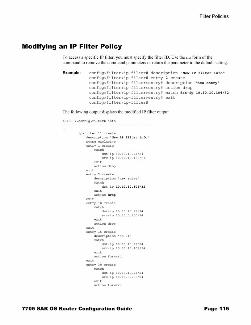
Filter Policies
Modifying an IP Filter PolicyTo access a specific IP filter, you must specify the filter ID. Use the no form of the command to remove the command parameters or return the parameter to the default setting.
Example: config>filter>ip-filter# description "New IP filter info"config>filter>ip-filter# entry 2 createconfig>filter>ip-filter>entry# description "new entry"config>filter>ip-filter>entry# action dropconfig>filter>ip-filter>entry# match dst-ip 10.10.10.104/32config>filter>ip-filter>entry# exitconfig>filter>ip-filter#
The following output displays the modified IP filter output.
A:ALU-7>config>filter# info----------------------------------------------.. ip-filter 11 create description "New IP filter info" scope exclusive entry 1 create match dst-ip 10.10.10.91/24 src-ip 10.10.10.106/24 exit action drop exit entry 2 create description "new entry" match dst-ip 10.10.10.104/32 exit action drop exit entry 10 create match dst-ip 10.10.10.91/24 src-ip 10.10.0.100/24 exit action drop exit entry 15 create description "no-91" match dst-ip 10.10.10.91/24 src-ip 10.10.10.103/24 exit action forward exit entry 30 create match dst-ip 10.10.10.91/24 src-ip 10.10.0.200/24 exit action forward
7705 SAR OS Router Configuration Guide Page 115

Filter Management Tasks
exit exit..----------------------------------------------A:ALU-7>config>filter#
Deleting a Filter PolicyBefore you can delete a filter, you must remove the filter association from the applied network interfaces.
Deleting a Filter from a Network Interface
To delete a filter from a network interface, enter the following CLI commands:
CLI Syntax: config>router# interface ip-int-nameingress{no filter | no filter ip ip-filter-id}
Example: config>router# interface b11config>router>if# ingressconfig>filter>if>ingress# no filter ip 2config>filter>if>ingress# exit
Deleting a Filter
After you have removed the filter from the network interface, use the following CLI syntax to delete the filter.
CLI Syntax: config>filter# no ip-filter filter-id
Example: config>filter# no ip-filter 2
Page 116 7705 SAR OS Router Configuration Guide

Filter Policies
Filter Command Reference
Command Hierarchies� Configuration Commands
→ IP Filter Log Configuration Commands → IP Filter Policy Configuration Commands
� Show Commands � Clear Commands � Monitor Commands
7705 SAR OS Router Configuration Guide Page 117

Filter Command Reference
Configuration Commands
IP Filter Log Configuration Commands
config� filter
� log log-id [create]� no log log-id
� description description-string� no description� destination memory num-entries� destination syslog syslog-id� no destination� [no] shutdown� summary
� [no] shutdown� summary-crit dst-addr� summary-crit src-addr� no summary-crit
� [no] wrap-around
IP Filter Policy Configuration Commands
config � filter
� ip-filter filter-id [create]� no ip-filter filter-id
� description description-string� no description� default-action {drop | forward} � renum old-entry-id new-entry-id� scope {exclusive | template}� no scope� entry entry-id [create] � no entry entry-id
� action [drop] � action forward� no action� description description-string� no description� log log-id� no log� match [protocol protocol-id]� no match
� dscp dscp-name� no dscp� dst-ip {ip-address/mask | ip-address netmask}� no dst-ip� dst-port {lt | gt | eq} dst-port-number � dst-port range start end� no dst-port
Page 118 7705 SAR OS Router Configuration Guide

Filter Policies
� fragment {true | false}� no fragment� icmp-code icmp-code � no icmp-code � icmp-type icmp-type � no icmp-type � ip-option ip-option-value [ip-option-mask]� no ip-option� multiple-option {true | false}� no multiple-option� option-present {true | false}� no option-present� src-ip{ip-address/mask | ip-address netmask}� no src-ip� src-port {lt | gt | eq} src-port-number � src-port range start end� no src-port� tcp-ack {true | false}� no tcp-ack� tcp-syn {true | false}� no tcp-syn
Show Commands
show� filter
� ip [ip-filter-id] [entry entry-id] [association | counters]� log [bindings]� log log-id [match string]
Clear Commands
clear� filter
� ip ip-filter-id [entry entry-id] [ingress | egress]� log log-id
Monitor Commands
monitor� filter ip ip-filter-id entry entry-id [interval seconds] [repeat repeat] [absolute | rate]
7705 SAR OS Router Configuration Guide Page 119

Filter Command Reference
Command Descriptions� Configuration Commands on page 121� Show Commands on page 139� Clear Commands on page 147� Monitor Commands on page 148
Page 120 7705 SAR OS Router Configuration Guide

Filter Policies
Configuration Commands
� Generic Commands on page 122� Filter Log Commands on page 123� Filter Policy Commands on page 126� General Filter Entry Commands on page 128� IP Filter Entry Commands on page 129� IP Filter Match Criteria Commands on page 132
7705 SAR OS Router Configuration Guide Page 121

Filter Command Reference
Generic Commands
description
Syntax description description-stringno description
Context config>filter>ip-filterconfig>filter>logconfig>filter>ip-filter>entry
Description This command creates a text description for a configuration context to help identify the content in the configuration file.
The no form of the command removes any description string from the context.
Default none
Parameters description-string � the description character string. Allowed values are any string up to 80 characters long composed of printable, 7-bit ASCII characters. If the string contains special characters (#, $, spaces, etc.), the entire string must be enclosed within double quotes.
shutdown
Syntax shutdownno shutdown
Context config>filter>logconfig>filter>log>summary
Description The shutdown command administratively disables the entity. The operational state of the entity is disabled as well as the operational state of any entities contained within. When disabled, an entity does not change, reset, or remove any configuration settings or statistics. Many objects must be shut down before they may be deleted. Many entities must be explicitly enabled using the no shutdown command.
Unlike other commands and parameters where the default state is not indicated in the configuration file, shutdown and no shutdown are always indicated in system-generated configuration files.
The no form of the command puts an entity into the administratively enabled state.
Default no shutdown
Page 122 7705 SAR OS Router Configuration Guide

Filter Policies
Filter Log Commands
log
Syntax log log-id [create]no log log-id
Context config>filter
Description This command enables the context to create a filter log policy.
The no form of the command deletes the filter log ID. The log cannot be deleted if there are filter entries configured to write to the log. All filter entry logging associations need to be removed before the log can be deleted.
Special Cases
Filter log 101 � Filter log 101 is the default log and is automatically created by the system. Filter log 101 is always a memory filter log and cannot be changed to a syslog filter log. The log size defaults to 1000 entries. The number of entries and wrap-around behavior can be edited.
Default log 101
Parameters log-id � the filter log ID destination expressed as a decimal integer
Values 101 to 199
destination
Syntax destination memory num-entriesdestination syslog syslog-idno destination
Context config>filter>log
Description This command configures the destination for filter log entries for the specified filter log ID.
Filter logs can be sent to either memory or an existing syslog server. If the filter log destination is memory, the maximum number of entries in the log must be specified.
The no form of the command deletes the filter log association.
Default no destination
Parameters num-entries � specifies that the destination of the filter log ID is a memory log. The num-entries value is the maximum number of entries in the filter log expressed as a decimal integer.
Values 1 to 50000
7705 SAR OS Router Configuration Guide Page 123

Filter Command Reference
syslog-id � specifies that the destination of the filter log ID is a syslog server. The syslog-id parameter is the identifier of the syslog server.
Values 1 to 10
summary
Syntax summary
Context config>filter>log
Description This command enables the context to configure log summarization. These settings apply only if syslog is the log destination.
summary-crit
Syntax summary-crit dst-addrsummary-crit src-addrno summary-crit
Context config>filter>log>summary
Description This command defines the key of the index of the mini-table. If key information is changed while summary is in the no-shutdown state, the filter summary mini-table is flushed and reconfigured with different key information. Log packets received during the reconfiguration time will be handled as if summary was not active.
The no form of the command reverts to the default parameter.
Default dst-addr
Parameters dst-addr � specifies that received log packets are summarized based on the destination IP address
src-addr � specifies that received log packets are summarized based on the source IP address
wrap-around
Syntax [no] wrap-around
Context config>filter>log
Description This command configures a memory filter log to store log entries until full or to store the most recent log entries (circular buffer).
Specifying wrap-around configures the memory filter log to store the most recent filter log entries (circular buffer). When the log is full, the oldest filter log entries are overwritten with new entries.
Page 124 7705 SAR OS Router Configuration Guide

Filter Policies
The no form of the command configures the memory filter log to accept filter log entries until full. When the memory filter log is full, filter logging for the log filter ID ceases.
Default wrap-around
7705 SAR OS Router Configuration Guide Page 125

Filter Command Reference
Filter Policy Commands
ip-filter
Syntax ip-filter filter-id [create]no ip-filter filter-id
Context config>filter
Description This command creates a configuration context for an IP filter policy.
IP filter policies specify either a forward or a drop action for packets based on the specified match criteria.
The IP filter policy, sometimes referred to as an access control list (ACL), is a template that can be applied to multiple network ports as long as the scope of the policy is template.
Any changes made to the existing policy, using any of the sub-commands, will be applied immediately to all network interfaces where this policy is applied.
The no form of the command deletes the IP filter policy. A filter policy cannot be deleted until it is removed from all network interfaces where it is applied.
Parameters filter-id � the IP filter policy ID number
Values 1 to 65535
create � keyword required when first creating the configuration context. When the context is created, you can navigate into the context without the create keyword.
default-action
Syntax default-action {drop | forward}
Context config>filter>ip-filter
Description This command specifies the action to be applied to packets when the packets do not match the specified criteria in all of the IP filter entries of the filter.
Default drop
Parameters drop � specifies that all packets will be dropped unless there is a specific filter entry that causes the packet to be forwarded
forward � specifies that all packets will be forwarded unless there is a specific filter entry that causes the packet to be dropped
Page 126 7705 SAR OS Router Configuration Guide

Filter Policies
renum
Syntax renum old-entry-id new-entry-id
Context config>filter>ip-filter
Description This command renumbers existing IP filter entries to properly sequence filter entries.
This may be required in some cases since the OS exits when the first match is found and executes the actions according to the accompanying action command. This requires that entries be sequenced correctly from most to least explicit.
Parameters old-entry-id � the entry number of an existing entry
Values 1 to 64
new-entry-id � the new entry number to be assigned to the old entry
Values 1 to 64
scope
Syntax scope {exclusive | template}no scope
Context config>filter>ip-filter
Description This command configures the filter policy scope as exclusive or template. If the scope of the policy is template and is applied to one or more network interfaces, the scope cannot be changed.
The no form of the command sets the scope of the policy to the default of template.
Default template
Parameters exclusive � when the scope of a policy is defined as exclusive, the policy can only be applied to a single entity (network port). If an attempt is made to assign the policy to a second entity, an error message will result. If the policy is removed from the entity, it will become available for assignment to another entity.
template � when the scope of a policy is defined as template, the policy can be applied to multiple network ports
7705 SAR OS Router Configuration Guide Page 127

Filter Command Reference
General Filter Entry Commands
entry
Syntax entry entry-id [create]no entry entry-id
Context config>filter>ip-filter
Description This command creates or edits an IP filter entry. Multiple entries can be created using unique entry-id numbers within the filter. The 7705 SAR implementation exits the filter on the first match found and executes the actions in accordance with the accompanying action command. For this reason, entries must be sequenced correctly from most to least explicit.
An entry might not have any match criteria defined (in which case, everything matches) but must have at least the keyword action for it to be considered complete. Entries without the action keyword will be considered incomplete and hence will be rendered inactive.
The no form of the command removes the specified entry from the IP filter. Entries removed from the IP filter are immediately removed from all network ports where that filter is applied.
Default none
Parameters entry-id � an entry-id uniquely identifies a match criteria and the corresponding action. It is recommended that multiple entries be given entry-ids in staggered increments. This allows users to insert a new entry in an existing policy without requiring renumbering of all the existing entries.
Values 1 to 64
create � keyword required when first creating the configuration context. When the context is created, you can navigate into the context without the create keyword.
Page 128 7705 SAR OS Router Configuration Guide
Filter Policies
IP Filter Entry Commands
action
Syntax action [drop]action [forward]no action
Context config>filter>ip-filter>entry
Description This command specifies what action to take (drop or forward) if the packets match the entry criteria. The action keyword must be entered and a keyword specified in order for the entry to be active.
Multiple action statements entered will overwrite previous action statements when defined.
The no form of the command removes the specified action statement. The filter entry is considered incomplete and is rendered inactive without the action keyword.
Default none
Parameters drop � specifies that packets matching the entry criteria will be dropped
forward � specifies that packets matching the entry criteria will be forwarded
If neither drop nor forward is specified, the filter action is No-Op and the filter entry is inactive.
log
Syntax log log-idno log
Context config>filter>ip-filter>entry
Description This command creates the context to enable filter logging for a filter entry and specifies the destination filter log ID.
The filter log ID must exist before a filter entry can be enabled to use the filter log ID.
The no form of the command disables logging for the filter entry.
Default no log
Parameters log-id � the filter log ID destination expressed as a decimal integer
Values 101 to 199
7705 SAR OS Router Configuration Guide Page 129

Filter Command Reference
match
Syntax match [protocol protocol-id]no match
Context config>filter>ip-filter>entry
Description This command enables the context to enter match criteria for the filter entry. When the match criteria have been satisfied, the action associated with the match criteria is executed.
If more than one match criterion (within one match statement) is configured, all criteria must be satisfied (AND function) before the action associated with the match is executed.
A match context may consist of multiple match criteria, but multiple match statements cannot be entered per entry.
The no form of the command removes the match criteria for the entry-id.
Parameters protocol � the protocol keyword configures an IP protocol to be used as an IP filter match criterion. The protocol type such as TCP or UDP is identified by its respective protocol number.
protocol-id � configures the decimal value representing the IP protocol to be used as an IP filter match criterion. Common protocol numbers include ICMP(1), TCP(6), UDP(17). The no form of the command removes the protocol from the match criteria.
Values 0 to 255 (values can be expressed in decimal, hexadecimal, or binary - DHB)keywords: none, crtp, crudp, egp, eigrp, encap, ether-ip, gre, icmp, idrp, igmp, igp, ip, ipv6, ipv6-frag, ipv6-icmp, ipv6-no-nxt, ipv6-opts, ipv6-route, isis, iso-ip, l2tp, ospf-igp, pim, pnni, ptp, rdp, rsvp, stp, tcp, udp, vrrp* � udp/tcp wildcard
Protocol Protocol ID Description
icmp 1 Internet Control Message
igmp 2 Internet Group Management
ip 4 IP in IP (encapsulation)
tcp 6 Transmission Control
egp 8 Exterior Gateway Protocol
igp 9 Any private interior gateway
udp 17 User Datagram
rdp 27 Reliable Data Protocol
ipv6 41 IPv6
ipv6-route 43 Routing Header for IPv6
ipv6-frag 44 Fragment Header for IPv6
Page 130 7705 SAR OS Router Configuration Guide

Filter Policies
idrp 45 Inter-Domain Routing Protocol
rsvp 46 Reservation Protocol
gre 47 General Routing Encapsulation
ipv6-icmp 58 ICMP for IPv6
ipv6-no-nxt 59 No Next Header for IPv6
ipv6-opts 60 Destination Options for IPv6
iso-ip 80 ISO Internet Protocol
eigrp 88 EIGRP
ospf-igp 89 OSPFIGP
ether-ip 97 Ethernet-within-IP Encapsulation
encap 98 Encapsulation Header
pnni 102 PNNI over IP
pim 103 Protocol Independent Multicast
vrrp 112 Virtual Router Redundancy Protocol
l2tp 115 Layer Two Tunneling Protocol
stp 118 Schedule Transfer Protocol
ptp 123 Performance Transparency Protocol
isis 124 ISIS over IPv4
crtp 126 Combat Radio Transport Protocol
crudp 127 Combat Radio User Datagram
Protocol Protocol ID Description
7705 SAR OS Router Configuration Guide Page 131

Filter Command Reference
IP Filter Match Criteria Commands
dscp
Syntax dscp dscp-nameno dscp
Context config>filter>ip-filter>entry>match
Description This command configures a DiffServ Code Point (DSCP) name to be used as an IP filter match criterion.
The no form of the command removes the DSCP match criterion.
Default no dscp
Parameters dscp-name � a DSCP name that has been previously mapped to a value using the dscp-name command. The DiffServ Code Point may only be specified by its name.
Values be|cp1|cp2|cp3|cp4|cp5|cp6|cp7|cs1|cp9|af11|cp11|af12|cp13|af13|cp15|cs2|cp17|af21|cp19|af22|cp21|af23|cp23|cs3|cp25|af31|cp27|af32|cp29|af33|cp31|cs4|cp33|af41|cp35|af42|cp37|af43|cp39|cs5|cp41|cp42|cp43|cp44|cp45|ef|cp47|nc1|cp49|cp50|cp51|cp52|cp53|cp54|cp55|nc2|cp57|cp58|cp59|cp60|cp61|cp62|cp63
dst-ip
Syntax dst-ip {ip-address/mask | ip-address netmask}no dst-ip
Context config>filter>ip-filter>entry>match
Description This command configures a destination IP address range to be used as an IP filter match criterion.
To match on the destination IP address, specify the address and its associated mask; for example, 10.1.0.0/16. The conventional notation of 10.1.0.0 255.255.0.0 may also be used.
The no form of the command removes the destination IP address match criterion.
Default none
Parameters ip-address � the IP prefix for the IP match criterion in dotted-decimal notation
Values 0.0.0.0 to 255.255.255.255
mask � the subnet mask length expressed as a decimal integer
Values 0 to 32
Page 132 7705 SAR OS Router Configuration Guide

Filter Policies
netmask � any mask expressed in dotted-decimal notation
Values 0.0.0.0 to 255.255.255.255
dst-port
Syntax dst-port {lt | gt | eq} dst-port-number dst-port range start end no dst-port
Context config>filter>ip-filter>entry>match
Description This command configures a destination TCP or UDP port number or port range for an IP filter match criterion.
The no form of the command removes the destination port match criterion.
Default none
Parameters lt | gt | eq � use relative to dst-port-number for specifying the port number match criteria:
lt specifies that all port numbers less than dst-port-number match
gt specifies that all port numbers greater than dst-port-number match
eq specifies that dst-port-number must be an exact match
dst-port-number � the destination port number to be used as a match criteria expressed as a decimal integer
Values 1 to 65535
range start end � specifies an inclusive range of port numbers to be used as a match criteria. The destination port numbers start and end are expressed as decimal integers.
Values 1 to 65535
fragment
Syntax fragment {true | false}no fragment
Context config>filter>ip-filter>entry>match
Description This command configures fragmented or non-fragmented IP packets as an IP filter match criterion.
The no form of the command removes the match criterion.
Default false
7705 SAR OS Router Configuration Guide Page 133

Filter Command Reference
Parameters true � configures a match on all fragmented IP packets. A match will occur for all packets that have either the MF (more fragment) bit set or have the Fragment Offset field of the IP header set to a non-zero value.
false � configures a match on all non-fragmented IP packets. Non-fragmented IP packets are packets that have the MF bit set to zero and have the Fragment Offset field also set to zero.
icmp-code
Syntax icmp-code icmp-codeno icmp-code
Context config>filter>ip-filter>entry>match
Description This command configures matching on an ICMP code field in the ICMP header of an IP packet as a filter match criterion.
This option is only meaningful if the protocol match criteria specifies ICMP (1).
The no form of the command removes the criterion from the match entry.
Default no icmp-code
Parameters icmp-code � the ICMP code values that must be present to match
Values 0 to 255 (values can be expressed in decimal, hexadecimal, or binary � DHB)keywords - none | network-unreachable | host-unreachable | protocol-unreachable | port-unreachable | fragmentation-needed | dest-network-unknown | dest-host-unknown
icmp-type
Syntax icmp-type icmp-typeno icmp-type
Context config>filter>ip-filter>entry>match
Description This command configures matching on the ICMP type field in the ICMP header of an IP packet as a filter match criterion.
This option is only meaningful if the protocol match criteria specifies ICMP (1).
The no form of the command removes the criterion from the match entry.
Default no icmp-type
Parameters icmp-type � the ICMP type values that must be present to match
Page 134 7705 SAR OS Router Configuration Guide

Filter Policies
Values 0 to 255 (values can be expressed in decimal, hexidecimal, or binary � DHB)keywords - none | echo-reply | dest-unreachable | echo-request | time-exceeded | parameter-problem
ip-option
Syntax ip-option ip-option-value [ip-option-mask]no ip-option
Context config>filter>ip-filter>entry>match
Description This command configures matching packets with a specific IP option or a range of IP options in the IP header as an IP filter match criterion.
The option type octet contains 3 fields:
� 1 bit copied flag (copy options in all fragments)� 2 bits option class� 5 bits option number
The no form of the command removes the match criterion.
Default no ip-option
Parameters ip-option-value � the 8-bit option type (can be entered using decimal, hexadecimal, or binary formats). The mask is applied as an AND to the option byte and the result is compared with the option value.
The decimal value entered for the match should be a combined value of the 8-bit option type field and not just the option number. Therefore, to match on IP packets that contain the Router Alert option (option number = 20), enter the option type of 148 (10010100).
Values 0 to 255
ip-option-mask � specifies a range of option numbers to use as the match criteria
This 8-bit mask can be entered using decimal, hexadecimal, or binary formats:
Default 255 (decimal) (exact match)
Values 0 to 255
Format Style Format Syntax Example
Decimal DDD 20
Hexadecimal 0xHH 0x14
Binary 0bBBBBBBBB 0b0010100
7705 SAR OS Router Configuration Guide Page 135

Filter Command Reference
multiple-option
Syntax multiple-option {true | false}no multiple-option
Context config>filter>ip-filter>entry>match
Description This command configures matching packets that contain more than one option field in the IP header as an IP filter match criterion.
The no form of the command removes the checking of the number of option fields in the IP header as a match criterion.
Default no multiple-option
Parameters true � specifies matching on IP packets that contain more than one option field in the header
false � specifies matching on IP packets that do not contain multiple option fields in the header
option-present
Syntax option-present {true | false}no option-present
Context config>filter>ip-filter>entry>match
Description This command configures matching packets that contain the option field or have an option field of 0 in the IP header as an IP filter match criterion.
The no form of the command removes the checking of the option field in the IP header as a match criterion.
Parameters true � specifies matching on all IP packets that contain the option field in the header. A match will occur for all packets that have the option field present. An option field of 0 is considered as no option present.
false � specifies matching on IP packets that do not have any option field present in the IP header (an option field of 0)
src-ip
Syntax src-ip {ip-address/mask | ip-address netmask}no src-ip
Context config>filter>ip-filter>entry>match
Description This command configures a source IP address range to be used as an IP filter match criterion.
To match on the source IP address, specify the address and its associated mask; for example, 10.1.0.0/16. The conventional notation of 10.1.0.0 255.255.0.0 may also be used.
Page 136 7705 SAR OS Router Configuration Guide

Filter Policies
The no form of the command removes the source IP address match criterion.
Default no src-ip
Parameters ip-address � the IP prefix for the IP match criterion in dotted-decimal notation
Values 0.0.0.0 to 255.255.255.255
mask � the subnet mask length expressed as a decimal integer
Values 0 to 32
netmask � any mask expressed in dotted-decimal notation
Values 0.0.0.0 to 255.255.255.255
src-port
Syntax src-port {lt | gt | eq} src-port-number src-port range start end no src-port
Context config>filter>ip-filter>entry>match
Description This command configures a source TCP or UDP port number or port range for an IP filter match criterion.
The no form of the command removes the source port match criterion.
Default no src-port
Parameters lt | gt | eq � use relative to src-port-number for specifying the port number match criteria:
lt specifies that all port numbers less than src-port-number match
gt specifies that all port numbers greater than src-port-number match
eq specifies that src-port-number must be an exact match
src-port-number � the source port number to be used as a match criteria expressed as a decimal integer
Values 1 to 65535
range start end � specifies an inclusive range of port numbers to be used as a match criteria. The destination port numbers start and end are expressed as decimal integers.
Values 1 to 65535
7705 SAR OS Router Configuration Guide Page 137
Filter Command Reference
tcp-ack
Syntax tcp-ack {true | false}no tcp-ack
Context config>filter>ip-filter>entry>match
Description This command configures matching on the ACK bit being set or reset in the control bits of the TCP header of an IP packet as an IP filter match criterion.
The no form of the command removes the criterion from the match entry.
Default no tcp-ack
Parameters true � specifies matching on IP packets that have the ACK bit set in the control bits of the TCP header of an IP packet
false � specifies matching on IP packets that do not have the ACK bit set in the control bits of the TCP header of the IP packet
tcp-syn
Syntax tcp-syn {true | false}no tcp-syn
Context config>filter>ip-filter>entry>match
Description This command configures matching on the SYN bit being set or reset in the control bits of the TCP header of an IP packet as an IP filter match criterion.
The SYN bit is normally set when the source of the packet wants to initiate a TCP session with the specified destination IP address.
The no form of the command removes the criterion from the match entry.
Default no tcp-syn
Parameters true � specifies matching on IP packets that have the SYN bit set in the control bits of the TCP header
false � specifies matching on IP packets that do not have the SYN bit set in the control bits of the TCP header
Page 138 7705 SAR OS Router Configuration Guide

Filter Policies
Show Commands
ip
Syntax ip [ip-filter-id] [entry entry-id] [association | counters]
Context show>filter
Description This command displays IP filter information.
Parameters ip-filter-id � displays detailed information for the specified filter ID and its filter entries
Values 1 to 65535
entry-id � displays information on the specified filter entry ID for the specified filter ID only
Values 1 to 64
associations � appends information as to where the filter policy ID is applied to the detailed filter policy ID output
counters � displays counter information for the specified filter ID
Output Filter Output � The following tables list filter output fields.
� Table 17: Show Filter Output Fields� Table 18: Show Filter Output Fields (Filter ID Specified)� Table 19: Show Filter Associations Output Fields� Table 20: Show Filter Counters Output Fields
Table 17: Show Filter Output Fields
Label Description
Filter Id The IP filter ID
Scope Template — the filter policy is of type template
Exclusive — the filter policy is of type exclusive
Applied No — the filter policy ID has not been applied
Yes — the filter policy ID is applied
Description The IP filter policy description
7705 SAR OS Router Configuration Guide Page 139

Filter Command Reference
Sample Output
A:ALU-1# show filter ip===============================================================================IP Filters===============================================================================Filter-Id Scope Applied Description-------------------------------------------------------------------------------1 Template Yes3 Template Yes6 Template Yes10 Template No11 Template No-------------------------------------------------------------------------------Num IP filters: 5===============================================================================A:ALU-1#
Table 18: Show Filter Output Fields (Filter ID Specified)
Label Description
Filter Id The IP filter policy ID
Scope Template — the filter policy is of type template
Exclusive — the filter policy is of type exclusive
Entries The number of entries configured in this filter ID
Applied No — the filter policy ID has not been applied
Yes — the filter policy ID is applied
Def. Action Drop — the default action for the filter ID for packets that do not match the filter entries is to drop
Filter Match Criteria
IP — indicates the filter is an IP filter policy
Entry The filter entry ID. If the filter entry ID indicates that the entry is Inactive, the filter entry is incomplete as no action has been specified.
Description The IP filter policy description
Src. IP The source IP address and prefix length match criterion
Dest. IP The destination IP address and prefix length match criterion
ICMP Type The ICMP type match criterion. Undefined indicates no ICMP type specified.
Page 140 7705 SAR OS Router Configuration Guide

Filter Policies
Sample Output
A:ALU-1# show filter ip 3===============================================================================IP Filter===============================================================================Filter Id : 3 Applied : YesScope : Template Def. Action : DropEntries : 1-------------------------------------------------------------------------------Filter Match Criteria : IP-------------------------------------------------------------------------------Entry : 10Description : this is a test ip-filter entryLog Id : n/aSrc. IP : 10.1.1.1/24 Src. Port : NoneDest. IP : 0.0.0.0/0 Dest. Port : NoneProtocol : Undefined Dscp : UndefinedICMP Type : Undefined ICMP Code : UndefinedFragment : Off Option-present : OffIP-Option : 0/0 Multiple Option: OffTCP-syn : Off TCP-ack : OffMatch action : DropIng. Matches : 0 pktsEgr. Matches : 0 pkts
===============================================================================A:ALU-1#
Match action Default — the filter does not have an explicit forward or drop match action specified. If the filter entry ID indicates that the entry is Inactive, the filter entry is incomplete as no action was specified.
Drop — drop packets matching the filter entry
Forward — forward packets matching the filter entry
Ing. Matches The number of ingress filter matches/hits for the filter entry
Src. Port The source TCP or UDP port number or port range
Dest. Port The destination TCP or UDP port number or port range
ICMP Code The ICMP code field in the ICMP header of an IP packet
Table 18: Show Filter Output Fields (Filter ID Specified) (Continued)
Label Description
7705 SAR OS Router Configuration Guide Page 141
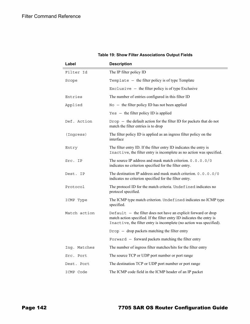
Filter Command Reference
Table 19: Show Filter Associations Output Fields
Label Description
Filter Id The IP filter policy ID
Scope Template — the filter policy is of type Template
Exclusive — the filter policy is of type Exclusive
Entries The number of entries configured in this filter ID
Applied No — the filter policy ID has not been applied
Yes — the filter policy ID is applied
Def. Action Drop — the default action for the filter ID for packets that do not match the filter entries is to drop
(Ingress) The filter policy ID is applied as an ingress filter policy on theinterface
Entry The filter entry ID. If the filter entry ID indicates the entry is Inactive, the filter entry is incomplete as no action was specified.
Src. IP The source IP address and mask match criterion. 0.0.0.0/0 indicates no criterion specified for the filter entry.
Dest. IP The destination IP address and mask match criterion. 0.0.0.0/0 indicates no criterion specified for the filter entry.
Protocol The protocol ID for the match criteria. Undefined indicates no protocol specified.
ICMP Type The ICMP type match criterion. Undefined indicates no ICMP type specified.
Match action Default — the filter does not have an explicit forward or drop match action specified. If the filter entry ID indicates the entry is Inactive, the filter entry is incomplete (no action was specified).
Drop — drop packets matching the filter entry
Forward — forward packets matching the filter entry
Ing. Matches The number of ingress filter matches/hits for the filter entry
Src. Port The source TCP or UDP port number or port range
Dest. Port The destination TCP or UDP port number or port range
ICMP Code The ICMP code field in the ICMP header of an IP packet
Page 142 7705 SAR OS Router Configuration Guide
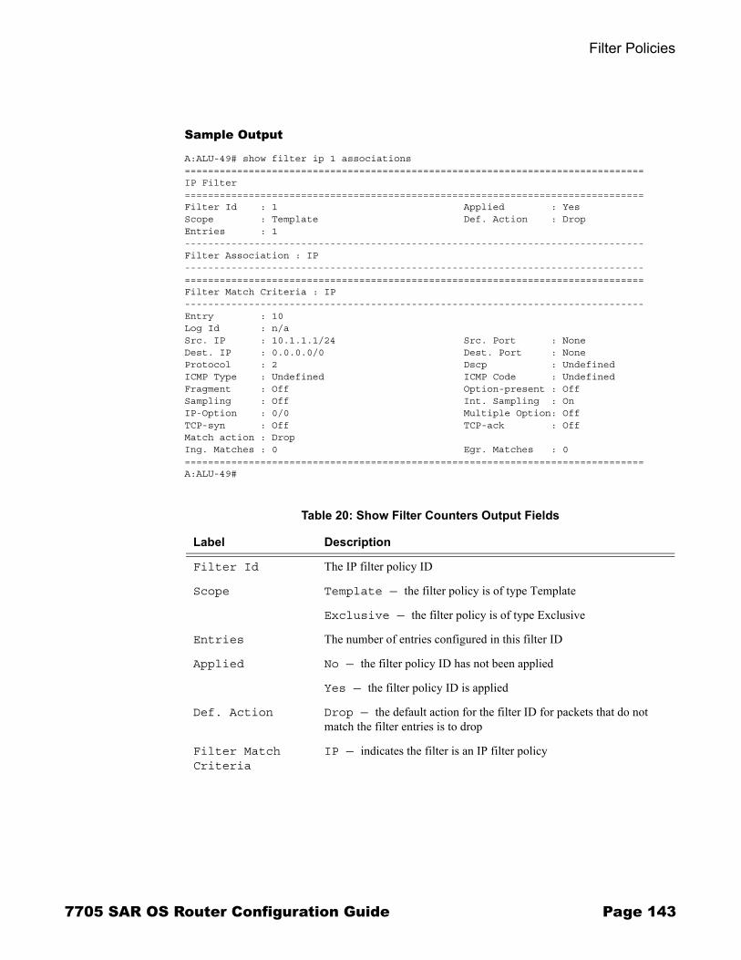
Filter Policies
Sample Output
A:ALU-49# show filter ip 1 associations===============================================================================IP Filter===============================================================================Filter Id : 1 Applied : YesScope : Template Def. Action : DropEntries : 1-------------------------------------------------------------------------------Filter Association : IP-------------------------------------------------------------------------------===============================================================================Filter Match Criteria : IP-------------------------------------------------------------------------------Entry : 10Log Id : n/aSrc. IP : 10.1.1.1/24 Src. Port : NoneDest. IP : 0.0.0.0/0 Dest. Port : NoneProtocol : 2 Dscp : UndefinedICMP Type : Undefined ICMP Code : UndefinedFragment : Off Option-present : OffSampling : Off Int. Sampling : OnIP-Option : 0/0 Multiple Option: OffTCP-syn : Off TCP-ack : OffMatch action : DropIng. Matches : 0 Egr. Matches : 0===============================================================================A:ALU-49#
Table 20: Show Filter Counters Output Fields
Label Description
Filter Id The IP filter policy ID
Scope Template — the filter policy is of type Template
Exclusive — the filter policy is of type Exclusive
Entries The number of entries configured in this filter ID
Applied No — the filter policy ID has not been applied
Yes — the filter policy ID is applied
Def. Action Drop — the default action for the filter ID for packets that do not match the filter entries is to drop
Filter Match Criteria
IP — indicates the filter is an IP filter policy
7705 SAR OS Router Configuration Guide Page 143

Filter Command Reference
Sample Output
A:ALU-1# show filter ip 3 counters===============================================================================IP Filter : 100 ===============================================================================Filter Id : 3 Applied : Yes Scope : Template Def. Action : Drop Entries : Not Available -------------------------------------------------------------------------------Filter Match Criteria : IP -------------------------------------------------------------------------------Entry : 10 Ing. Matches: 749 Egr. Matches : 0 Entry : 200 Ing. Matches: 0 Egr. Matches : 0 ===============================================================================A:ALU-1#
log
Syntax log [bindings]log log-id [match string]
Context show>filter
Description This command displays filter log information.
Parameters bindings � displays the number of filter logs currently available
log-id � the filter log ID destination expressed as a decimal integer
Values 101 to 199
string � specifies to display the log entries starting from the first occurrence of the specified string
Values up to 32 characters
Entry The filter entry ID. If the filter entry ID indicates the entry is (Inactive), the filter entry is incomplete as no action has been specified.
Ing. Matches The number of ingress filter matches/hits for the filter entry
Table 20: Show Filter Counters Output Fields (Continued)
Label Description
Page 144 7705 SAR OS Router Configuration Guide

Filter Policies
Output Filter Log Output � The following tables lists the filter log output fields.
� Table 21: Show Filter Log Output Fields� Table 22: Show Filter Log Bindings
Sample Output
A:ALU-1# show filter log
===============================================================================Filter Logs===============================================================================Log-Id Dest. Id/Entries Enabled Description-------------------------------------------------------------------------------101 Memory 1000 Yes Default filter log Wrap: Enabled
1 Entries Found===============================================================================A:ALU-1#
Table 21: Show Filter Log Output Fields
Label Description
Log-Id The filter log ID
Dest./Destination The destination of the filter log: memory or syslog
Id/Entries The number of entries configured for this filter log
Enabled Indicates whether the log is administratively enabled
Admin State The administrative state of the log: enabled or disabled
Description The description string configured for the filter log
Wrap Indicates whether the wrap-around function (circular buffer) is enabled
Maximum entries configured
The maximum number of entries allowed in this filter log
Number of entries logged
The number of entries in this filter log
7705 SAR OS Router Configuration Guide Page 145

Filter Command Reference
A:ALU-1# show filter log 101
===============================================================================Filter Log===============================================================================Admin state : EnabledDescription : Default filter logDestination : MemoryWrap : Enabled-------------------------------------------------------------------------------Maximum entries configured : 1000Number of entries logged : 0===============================================================================
Sample Output
A:ALU-1# show filter log bindings
===============================================================================Filter Log Bindings===============================================================================Total Log Instances (Allowed) : 2047Total Log Instances (In Use) : 1Total Log Bindings : 1
-------------------------------------------------------------------------------Type FilterId EntryId Log Instantiated------------------------------------------------------------------------------- Cpm 1 2 101 Yes===============================================================================
Table 22: Show Filter Log Bindings
Label Description
Total Log Instances (Allowed)
The maximum allowed instances of filter logs allowed on the system
Total Log Instances (In Use)
The instances of filter logs presently existing on the system
Total Log Bindings The count of the filter log bindings presently existing on the system
Type The type of filter: CPM or IP
FilterID The unique identifier of the filter
EntryID The unique identifier of an entry in the filter table
Log The filter log identifier
Instantiated Specifies if the filter log for this filter entry has been enabled
Page 146 7705 SAR OS Router Configuration Guide
Filter Policies
Clear Commands
ip
Syntax ip ip-filter-id [entry entry-id] [ingress | egress]
Context clear>filter
Description This command clears the counters associated with the IP filter policy.
By default, all counters associated with the filter policy entries are reset. The scope of which counters are cleared can be narrowed using the command line parameters.
Default Clears all counters associated with the IP filter policy entries.
Parameters ip-filter-id � the IP filter policy ID
Values 1 to 65535
entry-id � only the counters associated with the specified filter policy entry will be cleared
Values 1 to 64
ingress � only the ingress counters will be cleared
egress � only the egress counters will be cleared
log
Syntax log log-id
Context clear>filter
Description This command clears the entries associated with the specified filter log. The clear command applies only to logs whose destination is to memory.
Parameters log-id � the filter log ID destination expressed as a decimal integer
Values 101 to 199
7705 SAR OS Router Configuration Guide Page 147

Filter Command Reference
Monitor Commands
filter
Syntax filter ip ip-filter-id entry entry-id [interval seconds] [repeat repeat] [absolute | rate]
Context monitor
Description This command monitors the counters associated with the IP filter policy.
Parameters ip-filter-id � the IP filter policy ID
Values 1 to 65535
entry-id � only the counters associated with the specified filter policy entry will be monitored
Values 1 to 64
seconds � configures the interval for each display in seconds
Values 3 to 60
Default 5 seconds
repeat � configures how many times the command is repeated
Values 1 to 999
Default 10
absolute � when the absolute keyword is specified, the raw statistics are displayed without processing. No calculations are performed on the delta or rate statistics.
rate � when the rate keyword is specified, the rate-per-second for each statistic is displayed instead of the delta
Page 148 7705 SAR OS Router Configuration Guide

Route Policies
In This ChapterThis chapter provides information about configuring route policies.
Topics in this chapter include:
� Configuring Route Policies on page 150→ Policy Statements on page 151
� Route Policy Configuration Process Overview on page 153� Configuration Notes on page 154� Configuring Route Policies with CLI on page 155� Route Policy Command Reference on page 169
7705 SAR OS Router Configuration Guide Page 149

Configuring Route Policies
Configuring Route PoliciesRoute policies are used to manage the label database for MPLS and to control entries to the routing table for dynamic routing.
For managing the label database, route policies can be used to configure which labels should be learned or advertised. With the use of route policies, labels from a neighbor can be configured; that is, labels from the specified neighbor can be added to the label information base (LIB) and labels advertised by certain neighbors can be discarded. Label learning of MPLS packets and, as a result, how the MPLS packets are forwarded, are based on the defined policies, if there are any. If no route policies are defined, all advertised labels received from neighbors are learned and placed in the LIB.
For routing, the 7705 SAR supports two databases to store routes. The routing database (RIB) is composed of the routing information learned by the routing protocols, including static routes. The forwarding database (FIB) is composed of the routes actually used to forward traffic through a router. In addition, link-state databases are maintained by interior gateway protocols (IGPs) such as IS-IS and OSPF. Release 2.0 of the 7705 SAR supports OSPF only. Refer to the 7705 SAR OS Routing Protocols Guide for information on OSPF.
Routing protocols calculate the best route to each destination and place these routes in the forwarding table. The routes in the forwarding table are used to forward IP packets to neighbors.
As an example, operators can configure a routing policy that will not place routes associated with a specific origin in the routing table. These routes will not be used to forward data packets and these routes are not advertised by the routing protocol to neighbors.
Routing policies control the size and content of the routing tables, the routes that are advertised, and the best route to take to reach a destination. Careful planning is essential to implement route policies that can affect the flow of routing information throughout the network. Before configuring and applying a route policy, operators should develop an overall plan and strategy to accomplish their intended routing actions.
There are no default route policies. Each policy must be created explicitly and applied. Policy parameters are modifiable.
Page 150 7705 SAR OS Router Configuration Guide

Route Policies
Policy StatementsRoute policies contain policy statements containing ordered entries that contain match conditions and actions that you specify. The entries should be sequenced from the most explicit to the least explicit.
The process can stop when the first complete match is found and the router executes the action defined in the entry, either to accept or reject packets that match the criteria or proceed to the next entry or the next policy. You can specify matching criteria based on source or particular properties of a route.
You can also provide more matching conditions by specifying criteria such as:
� Prefix list � a named list of prefixes � From criteria � a route�s source
Default Action Behavior
The default action specifies how packets are to be processed when a policy related to the route is not explicitly configured. The following default actions are applied in the event that:
� a route policy does not specify a matching condition; all the routes being compared with the route policy are considered to be matches
� a match does not occur when the last entry in the last policy is evaluated
If a default action is defined for one or more of the configured route policies, then the default action is handled as follows.
� The default action can be set to all available action states, including accept, reject, next-entry, and next-policy.
� If the action states accept or reject, the policy evaluation terminates and the appropriate result is returned.
� If a default action is defined and no matches occurred with the entries in the policy, the default action is used.
� If a default action is defined and one or more matches occurred with the entries of the policy, the default action is not used.
7705 SAR OS Router Configuration Guide Page 151

Configuring Route Policies
Denied IP Prefixes
The following IP address prefixes are not allowed by the routing protocols and the Route Table Manager and are not be populated within the forwarding table:
� 0.0.0.0/8 or longer� 127.0.0.0/8 or longer� 224.0.0.0/4 or longer� 240.0.0.0/4 or longer
Any other prefixes that need to be filtered can be filtered explicitly using route policies.
Page 152 7705 SAR OS Router Configuration Guide

Route Policies
Route Policy Configuration Process OverviewFigure 4 displays the process to provision basic route policy parameters.
Figure 4: Route Policy Configuration and Implementation Flow
TURN UP
START
CONFIGURE PREFIX LISTS
CONFIGURE ROUTE POLICY
APPLY ROUTE POLICIES
7705 SAR OS Router Configuration Guide Page 153
Configuration Notes
Configuration NotesWhen configuring policy statements, the policy statement name must be unique.
Reference SourcesFor information on supported IETF drafts and standards, as well as standard and proprietary MIBS, refer to Standards and Protocol Support on page 185.
Page 154 7705 SAR OS Router Configuration Guide

Route Policies
Configuring Route Policies with CLI This section provides information to configure route policies using the command line interface.
Topics in this section include:
� Route Policy Configuration Overview on page 156→ When to Create Routing Policies on page 156→ Policy Evaluation on page 157
� Basic Route Policy Configuration on page 159� Configuring Route Policy Components on page 160
→ Beginning the Policy Statement on page 160→ Creating a Route Policy on page 161→ Configuring a Default Action on page 162→ Configuring an Entry on page 163→ Configuring a Prefix List on page 165
� Route Policy Configuration Management Tasks on page 166→ Editing Policy Statements and Parameters on page 166→ Deleting an Entry on page 167→ Deleting a Policy Statement on page 168
7705 SAR OS Router Configuration Guide Page 155

Route Policy Configuration Overview
Route Policy Configuration OverviewRoute policies allow you to configure routing according to specifically defined policies. You can create policies and entries to allow or deny paths based on parameters such as source address.
Policies can be as simple or complex as required. A simple policy can block routes for a specific location or IP address. More complex policies can be configured using numerous policy statement entries containing matching conditions to specify whether to accept or reject the route, control how a series of policies are evaluated, and manipulate the characteristics associated with a route.
When to Create Routing PoliciesRoute policies are created in the config>router context. There are no default route policies. Each route policy must be explicitly created and applied. Applying route policies can introduce more efficiency as well as more complexity to the capabilities of the 7705 SAR.
Route policies can be mainly used to manage the label database for MPLS. Route policies can be used to configure which labels should be learned or advertised. Labels from a neighbor can be configured, and labels advertised from certain neighbors can be discarded.
Route policies are also used to control the size and content of the OSPF routing table, the routes that are advertised, and the best route to take to reach a destination.
Routing protocols have default behaviors for the import and export of routing information. For OSPF, the default route policy actions are as follows:
� import � not applicable; all OSPF routes are accepted from OSPF neighbors and cannot be controlled by route policies
� export (internal routes) � all OSPF routes are automatically advertised to all neighbors
� export (external routes) � all non-OSPF learned routes are not advertised to OSPF neighbors
Page 156 7705 SAR OS Router Configuration Guide

Route Policies
Policy EvaluationRouting policy statements can consist of one or several entries. The entries specify the matching criteria. A label is compared to the first entry in the policy statement. If it matches, the specified entry action is taken, either accepted or rejected. If the action is to accept or reject the label, that action is taken and the evaluation of the label ends.
If the label does not match the first entry, the label is compared to the next entry (if more than one is configured) in the policy statement. If there is a match with the second entry, the specified action is taken. If the action is to accept or reject the label, that action is taken and the evaluation of the label ends, and so on.
Each route policy statement can have a default-action clause defined. If a default action is defined for one or more of the configured route policies, the default action should be handled in the following ways.
� The process stops when the first complete match is found and executes the action defined in the entry.
� If the packet does not match any of the entries, the system executes the default action specified in the policy statement.
Route policies can also match a given route policy entry and continue to search for other entries within either the same route policy or the next route policy by specifying thenext-entry or next-policy option in the entry�s action command. Policies can be constructed to support multiple states to the evaluation and setting of various route attributes.
7705 SAR OS Router Configuration Guide Page 157
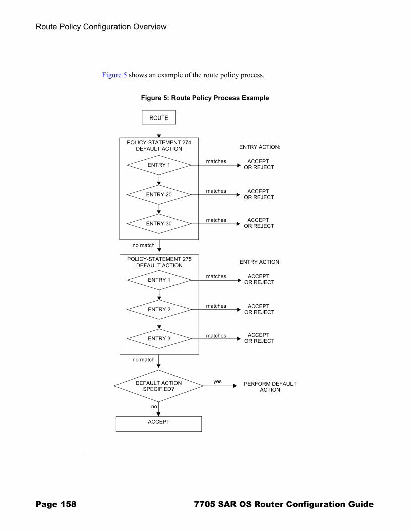
Route Policy Configuration Overview
Figure 5 shows an example of the route policy process.
Figure 5: Route Policy Process Example
ROUTE
POLICY-STATEMENT 274DEFAULT ACTION
ENTRY 1
ENTRY 20
ENTRY 30
ENTRY ACTION:
ACCEPT OR REJECT
ACCEPT OR REJECT
ACCEPT OR REJECT
POLICY-STATEMENT 275DEFAULT ACTION
ENTRY 1
ENTRY 2
ENTRY 3
ENTRY ACTION:
ACCEPT OR REJECT
ACCEPT OR REJECT
ACCEPT OR REJECT
matches
matches
matches
matches
matches
matches
no match
no match
DEFAULT ACTIONSPECIFIED?
no
yes
ACCEPT
PERFORM DEFAULTACTION
Page 158 7705 SAR OS Router Configuration Guide

Route Policies
Basic Route Policy ConfigurationThis section provides information on configuring route policies and shows configuration examples of common tasks.
The minimal route policy parameters that need to be configured are:
� policy statement with the following parameters specified:→ at least one entry → entry action
The following is an example of route policy configuration.
A:ALU-B>config>router>policy-options# info----------------------------------------------
policy-statement "Specifyprefixlist" entry 1 from prefix-list “list1” exit action accept exit exit----------------------------------------------A:ALU-B>config>router>policy-options#
7705 SAR OS Router Configuration Guide Page 159
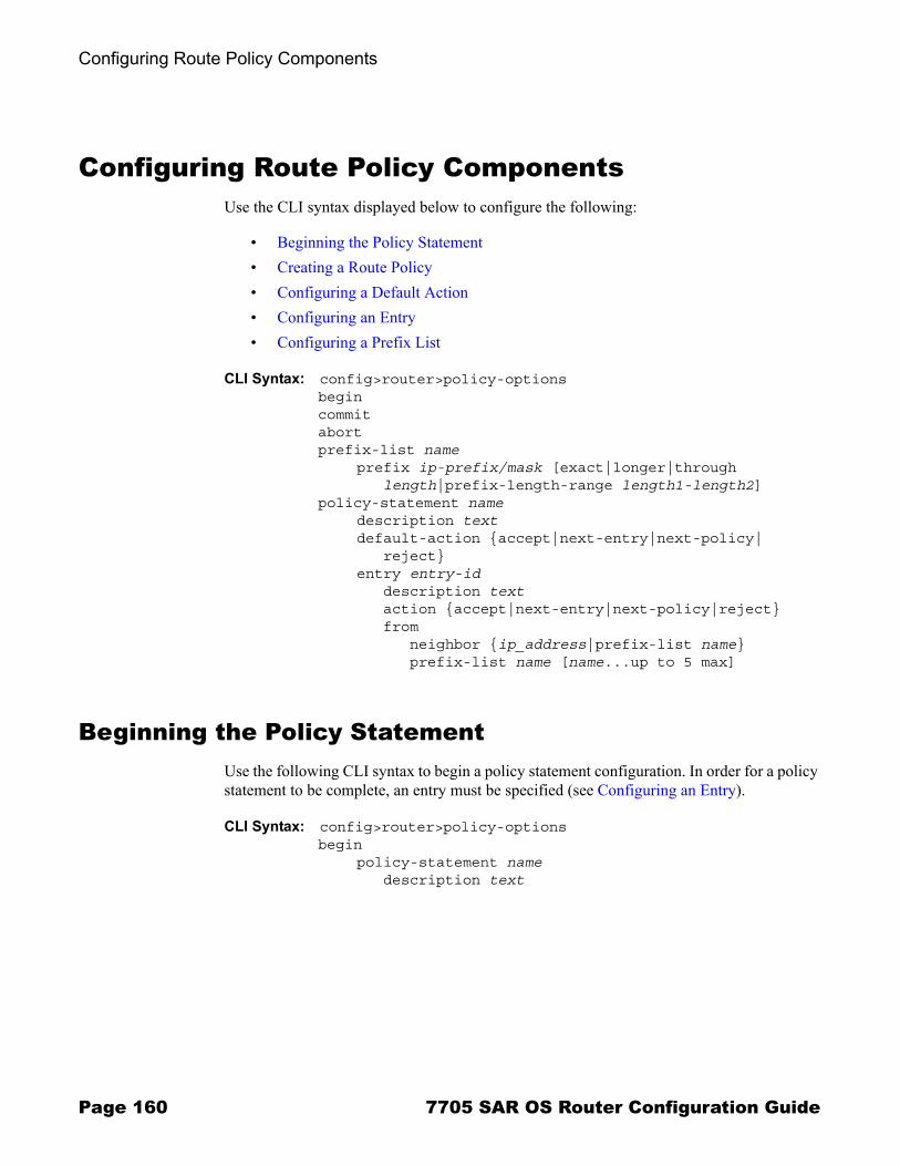
Configuring Route Policy Components
Configuring Route Policy ComponentsUse the CLI syntax displayed below to configure the following:
� Beginning the Policy Statement� Creating a Route Policy� Configuring a Default Action� Configuring an Entry� Configuring a Prefix List
CLI Syntax: config>router>policy-optionsbegincommitabortprefix-list name
prefix ip-prefix/mask [exact|longer|through length|prefix-length-range length1-length2]
policy-statement namedescription textdefault-action {accept|next-entry|next-policy|
reject}entry entry-id
description textaction {accept|next-entry|next-policy|reject}from
neighbor {ip_address|prefix-list name}prefix-list name [name...up to 5 max]
Beginning the Policy Statement Use the following CLI syntax to begin a policy statement configuration. In order for a policy statement to be complete, an entry must be specified (see Configuring an Entry).
CLI Syntax: config>router>policy-optionsbegin
policy-statement namedescription text
Page 160 7705 SAR OS Router Configuration Guide

Route Policies
The following error message displays if you try to enter a policy options command without entering begin first.
A:ALU-B>config>router>policy-options# policy-statement “allow all”MINOR: CLI The policy-options must be in edit mode by calling begin before any changes can be made.
The following example displays policy statement configuration command usage. These commands are configured in the config>router context.
Example: config>router# policy-optionspolicy-options# begin
There are no default policy statement options. All parameters must be explicitly configured.
Creating a Route PolicyTo enter the mode to create or edit route policies, you must enter the begin keyword at the config>router>policy-options prompt. Other editing commands include:
� the commit command, which saves changes made to route policies during a session � the abort command, which discards changes that have been made to route policies
during a session
Use the following CLI syntax to enter the edit mode:
CLI Syntax: config>router>policy-optionsbegin
The following example displays some commands to configure a policy statement. Policy option commands are configured in the config>router context. Use the commit command to save the changes.
Example: config>router>policy-options# beginpolicy-options# policy-statement "allow all"policy-options>policy-statement$ description "General
Policy"policy-options>policy-statement>default# entry 1policy-options>policy-statement>entry$ action acceptpolicy-options>policy-statement>entry# exitpolicy-options>policy-statement# exitpolicy-options# commit
The following error message displays if you try to modify a policy option without entering begin first.
7705 SAR OS Router Configuration Guide Page 161
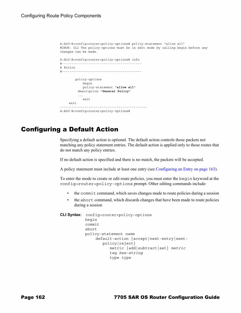
Configuring Route Policy Components
A:ALU-B>config>router>policy-options# policy-statement “allow all”MINOR: CLI The policy-options must be in edit mode by calling begin before any changes can be made.
A:ALU-B>config>router>policy-options# info#------------------------------------------# Policy#------------------------------------------
policy-options begin policy-statement "allow all"
description "General Policy"...
exitexit
----------------------------------------------A:ALU-B>config>router>policy-options#
Configuring a Default Action Specifying a default action is optional. The default action controls those packets not matching any policy statement entries. The default action is applied only to those routes that do not match any policy entries.
If no default action is specified and there is no match, the packets will be accepted.
A policy statement must include at least one entry (see Configuring an Entry on page 163).
To enter the mode to create or edit route policies, you must enter the begin keyword at the config>router>policy-options prompt. Other editing commands include:
� the commit command, which saves changes made to route policies during a session � the abort command, which discards changes that have been made to route policies
during a session
CLI Syntax: config>router>policy-optionsbegincommitabortpolicy-statement name
default-action {accept|next-entry|next-policy|reject}
metric {add|subtract|set} metrictag hex-stringtype type
Page 162 7705 SAR OS Router Configuration Guide

Route Policies
The following example displays default action configuration command usage. These commands are configured in the config>router>policy-options context.
Example: config>router>policy-options# policy-statement "1"policy-statement$ default-action accept
The following example displays the default action configuration:
A:ALU-B>config>router>policy-options# info---------------------------------------------- policy-statement "1" default-action accept type 1 exit exit----------------------------------------------A:ALU-B>config>router>policy-options#
Configuring an EntryAn entry action must be specified. The other parameters in the entry action context are optional.
CLI Syntax: config>router>policy-optionsbegincommitabortpolicy-statement name
entry entry-iddescription textaction {accept|next-entry|next-policy|reject}from
area area-idneighbor {ip-address | prefix-list name}prefix-list name [name...(up to 5 max)]protocol protocoltag tagtype type
toneighbor {ip-address | prefix-list name}prefix-list name [name...(up to 5 max)]protocol protocol
7705 SAR OS Router Configuration Guide Page 163

Configuring Route Policy Components
The following example displays entry command usage. These commands are configured in the config>router>policy-options context.
Example: config>router>policy-options# policy-statement "1"policy-statement# entry 1policy-statement>entry$ frompolicy-statement>entry>from# neighbor 10.10.10.104policy-statement>entry>from# exitpolicy-statement>entry# action acceptpolicy-statement>entry>action# exitpolicy-statement>entry# exitpolicy-statement# entry 2policy-statement>entry$ frompolicy-statement>entry>from# protocol ospfpolicy-statement>entry>from# exitpolicy-statement>entry$ topolicy-statement>entry>to# protocol ospfpolicy-statement>entry>to# neighbor 10.10.0.91policy-statement>entry>to# exitpolicy-statement>entry# action acceptpolicy-statement>entry>action# exit
The following example displays entry parameters and includes the default action parameters that were displayed in the previous section.
A:ALU-B>config>router>policy-options# info---------------------------------------------- policy-statement "1" entry 1 from neighbor 10.10.10.104 exit action accept exit exit entry 2
from protocol ospf
exitto
protocol ospf neighbor 10.10.0.91 exit action accept exit exit default-action accept . . . exit exit----------------------------------------------A:ALU-B>config>router>policy-options#
Page 164 7705 SAR OS Router Configuration Guide

Route Policies
Configuring a Prefix ListUse the following CLI syntax to configure a prefix list:
CLI Syntax: prefix-list nameprefix ip-prefix/mask [exact|longer|through
length|prefix-length-range length1-length2]
The following example displays prefix list configuration command usage. These commands are configured in the config>router context.
Example: config>router>policy-options# prefix-listpolicy-options# prefix-list westernpolicy-options>prefix-list# prefix 10.10.0.1/32policy-options>prefix-list# prefix 10.10.0.2/32policy-options>prefix-list# prefix 10.10.0.3/32policy-options>prefix-list# prefix 10.10.0.4/32
The following example displays the prefix list configuration.
A:ALU-B>config>router>policy-options# info---------------------------------------------- prefix-list "western" prefix 10.10.0.1/32 exact prefix 10.10.0.2/32 exact prefix 10.10.0.3/32 exact prefix 10.10.0.4/32 exact exit----------------------------------------------A:ALU-B>config>router>policy-options>#
7705 SAR OS Router Configuration Guide Page 165

Route Policy Configuration Management Tasks
Route Policy Configuration Management TasksThis section discusses the following route policy configuration management tasks:
� Editing Policy Statements and Parameters� Deleting an Entry� Deleting a Policy Statement
Editing Policy Statements and ParametersRoute policy statements can be edited to modify, add, or delete parameters. To enter edit mode, you must enter the begin keyword at the config>router>policy-options prompt. Other editing commands include:
� the commit command, which saves changes made to route policies during a session � the abort command, which discards changes that have been made to route policies
during a session
The following example displays some commands to configure a policy statement. These commands are configured in the config>router>policy-options context.
Example: config>router>policy-options# beginpolicy-options# policy-statement "1"policy-statement# description "Level 1”policy-statement# entry 4policy-statement>entry$ description “new entry”policy-statement>entry# frompolicy-statement>entry>from$ prefix-list “from hq”policy-statement>entry>from# exitpolicy-statement>entry# action rejectpolicy-statement>entry# commitpolicy-statement>entry# exit
The following example displays the changed configuration.
A:ALU-B>config>router>policy-options>policy-statement# info---------------------------------------------- description "Level 1" entry 1 from neighbor 10.10.10.104 exit action accept exit exit entry 2 from
Page 166 7705 SAR OS Router Configuration Guide

Route Policies
prefix-list list1 exit from neighbor 10.10.0.91 exit action accept exit exit entry 4 description "new entry" from prefix-list “from hq” exit action reject exit default-action accept exit----------------------------------------------A:ALU-B>config>router>policy-options>policy-statement#
Deleting an EntryUse the following CLI syntax to delete a policy statement entry:
CLI Syntax: config>router>policy-optionsbegincommitabortpolicy-statement name
no entry entry-id
The following example displays the commands required to delete a policy statement entry.
Example: config>router>policy-options# beginpolicy-options# policy-statement "1"policy-options>policy-statement# no entry 4policy-options>policy-statement# commit
7705 SAR OS Router Configuration Guide Page 167

Route Policy Configuration Management Tasks
Deleting a Policy StatementUse the following CLI syntax to delete a policy statement:
CLI Syntax: config>router>policy-optionsbegincommitabortno policy-statement name
The following example displays the commands required to delete a policy statement.
Example: config>router>policy-options# beginpolicy-options# no policy-statement 1policy-options# commit
Page 168 7705 SAR OS Router Configuration Guide

Route Policies
Route Policy Command Reference
Command Hierarchies� Route Policy Configuration Commands� Show Commands
Route Policy Configuration Commands
config � [no] router
� [no] policy-options� begin� commit� abort� [no] policy-statement name
� description description-string� no description� default-action {accept | next-entry | next-policy | reject}� no default-action
� metric {add | subtract | set} metric� no metric� tag hex-string� no tag� type type� no type
� entry entry-id� no entry
� description description-string� no description� action {accept | next-entry | next-policy | reject}� no action
� metric {add | subtract | set} metric� no metric� tag hex-string� no tag� type type� no type
� [no] from� area area-id� no area� neighbor {ip-address | prefix-list name}� no neighbor� prefix-list name [name...(up to 5 max)]� no prefix-list
7705 SAR OS Router Configuration Guide Page 169

Route Policy Command Reference
� protocol protocol� no protocol� tag tag� no tag� type type� no type
� [no] to� neighbor {ip-address | prefix-list name}� no neighbor� prefix-list name [name...(up to 5 max)]� no prefix-list� protocol protocol� no protocol
� [no] prefix-list name� [no] prefix ip-prefix/mask [exact | longer | through length | prefix-
length-range length1-length2]
Show Commands
show� router router-name
� policy [name | prefix-list name | admin]
Page 170 7705 SAR OS Router Configuration Guide
Route Policies
Command Descriptions� Configuration Commands on page 172� Show Commands on page 184
7705 SAR OS Router Configuration Guide Page 171

Route Policy Command Reference
Configuration Commands
� Generic Commands on page 173� Route Policy Options on page 175� Route Policy Prefix Commands on page 176� Route Policy Entry Match Commands on page 177� Route Policy Action Commands on page 181
Page 172 7705 SAR OS Router Configuration Guide

Route Policies
Generic Commands
abort
Syntax abort
Context config>router>policy-options
Description This command discards changes made to a route policy.
Default none
begin
Syntax begin
Context config>router>policy-options
Description This command enters the mode to create or edit route policies.
Default none
commit
Syntax commit
Context config>router>policy-options
Description This command saves changes made to a route policy.
Default none
7705 SAR OS Router Configuration Guide Page 173

Route Policy Command Reference
description
Syntax description description-stringno description
Context config>router>policy-options>policy-statementconfig>router>policy-options>policy-statement>entry
Description This command creates a text description that is stored in the configuration file to help identify the content of the entity.
The no form of the command removes the string from the configuration.
Default none
Parameters description-string � the description character string. Allowed values are any string up to 80 characters long composed of printable, 7-bit ASCII characters. If the string contains special characters (#, $, spaces, etc.), the entire string must be enclosed within double quotes.
Page 174 7705 SAR OS Router Configuration Guide

Route Policies
Route Policy Options
policy-options
Syntax [no] policy-options
Context config>router
Description This command enables the context to configure route policies. Route policies are applied to the routing protocol.
The no form of the command deletes the route policy configuration.
Default none
policy-statement
Syntax [no] policy-statement name
Context config>router>policy-options
Description This command creates the context to configure a route policy statement.
Route policy statements control the flow of routing information from a specific protocol or protocols.
The policy-statement is a logical grouping of match and action criteria. A single policy-statement can affect routing in one or more protocols and/or one or more protocols� peers/neighbors. A single policy-statement can also affect the export of routing information.
The no form of the command deletes the policy statement.
Default no policy-statement � No route policy statements are defined.
Parameters name � the route policy statement name. Allowed values are any string up to 32 characters long composed of printable, 7-bit ASCII characters. If the string contains special characters (#, $, spaces, etc.), the entire string must be enclosed within double quotes.
7705 SAR OS Router Configuration Guide Page 175

Route Policy Command Reference
Route Policy Prefix Commands
prefix-list
Syntax [no] prefix-list name
Context config>router>policy-options
Description This command creates a context to configure a prefix list to use in route policy entries.
The no form of the command deletes the named prefix list.
Default none
Parameters name � the prefix list name. Allowed values are any string up to 32 characters long composed of printable, 7-bit ASCII characters. If the string contains special characters (#, $, spaces, etc.), the entire string must be enclosed within double quotes.
prefix
Syntax [no] prefix ip-prefix/mask [exact | longer | through length | prefix-length-range length1-length2]
Context config>router>policy-options>prefix-list
Description This command creates a prefix entry in the route policy prefix list.
The no form of the command deletes the prefix entry from the prefix list.
Parameters ip-prefix � the IP prefix for the prefix list entry in dotted-decimal notation
Values a.b.c.d (host bits must be 0)
mask � the IP prefix length
Values 0 to 32
exact � specifies that the prefix list entry only matches the route with the specified ip-prefix and mask (prefix length) values
longer � specifies that the prefix list entry matches any route that matches the specified ip-prefix and mask values greater than the specified mask
through length � specifies that the prefix list entry matches any route that matches the specified ip-prefix and has a mask value within the specified length values
Values 0 to 32
prefix-length-range length1 - length2 � specifies that a route must match the most significant bits and have a mask value within the given range
Values 0 to 32, length2 > length1
Page 176 7705 SAR OS Router Configuration Guide

Route Policies
Route Policy Entry Match Commands
entry
Syntax entry entry-idno entry
Context config>router>policy-options>policy-statement name
Description This command creates the context to edit route policy entries within the route policy statement.
Multiple entries can be created using unique entries. The 7705 SAR OS exits the filter when the first match is found and executes the action specified. For this reason, entries must be sequenced correctly from most to least explicit.
An entry does not require matching criteria defined (in which case, everything matches) but must have an action defined in order to be considered complete. Entries without an action are considered incomplete and will be rendered inactive.
The no form of the command removes the specified entry from the route policy statement.
Default none
Parameters entry-id � the entry ID expressed as a decimal integer. An entry-id uniquely identifies match criteria and the corresponding action. It is recommended that multiple entries be given entry-ids in staggered increments. This allows users to insert a new entry in an existing policy without requiring renumbering of all the existing entries.
Values 1 to 4294967295
from
Syntax [no] from
Context config>router>policy-options>policy-statement>entry
Description This command creates the context to configure policy match criteria based on a route�s source or the protocol from which the route is received.
If no condition is specified, all route sources are considered to match.
The no form of the command deletes the source match criteria for the route policy statement entry.
7705 SAR OS Router Configuration Guide Page 177
Route Policy Command Reference
to
Syntax [no] to
Context config>router>policy-options>policy-statement>entry
Description This command creates the context to configure export policy match criteria based on a route�s destination or the protocol into which the route is being advertised.
If no condition is specified, all route destinations are considered to match.
The to command context only applies to export policies. If it is used for an import policy, match criteria is ignored.
The no form of the command deletes export match criteria for the route policy statement entry.
area
Syntax area area-idno area
Context config>router>policy-options>policy-statement>entry>from
Description This command configures an OSPF area as a route policy match criterion.
This match criterion is only used in export policies.
All OSPF routes (internal and external) are matched using this criterion if the best path for the route is by the specified area.
The no form of the command removes the OSPF area match criterion.
Default none
Parameters area-id � the OSPF area ID expressed in dotted-decimal notation or as a 32-bit decimal integer
Values 0.0.0.0 to 255.255.255.255 (dotted-decimal), 0 to 4294967295 (decimal)
neighbor
Syntax neighbor {ip-address | prefix-list name}no neighbor
Context config>router>policy-options>policy-statement>entry>fromconfig>router>policy-options>policy-statement>entry>to
Description This command specifies the neighbor address as found in the source address of the actual join and prune message as a filter criterion. If no neighbor is specified, any neighbor is considered a match.
The no form of the of the command removes the neighbor IP match criterion from the configuration.
Page 178 7705 SAR OS Router Configuration Guide

Route Policies
Default no neighbor � matches any neighbor
Parameters ip-address � the neighbor IP address in dotted-decimal notation
Values ip-address a.b.c.d
name � the prefix list name. Allowed values are any string up to 32 characters long composed of printable, 7-bit ASCII characters. If the string contains special characters (#, $, spaces, etc.), the entire string must be enclosed within double quotes.
The name specified must already be defined.
prefix-list
Syntax prefix-list name [name...up to 5 max]no prefix-list
Context config>router>policy-options>policy-statement>entry>fromconfig>router>policy-options>policy-statement>entry>to
Description This command configures a prefix list as a match criterion for a route policy statement entry.
If no prefix list is specified, any network prefix is considered a match.
The prefix lists specify the network prefix (this includes the prefix and length) that a specific policy entry applies to.
Up to five prefix list names can be specified.
The no form of the command removes the prefix list match criterion.
Default no prefix-list � matches any network prefix
Parameters name � the prefix list name. Allowed values are any string up to 32 characters long composed of printable, 7-bit ASCII characters. If the string contains special characters (#, $, spaces, etc.), the entire string must be enclosed within double quotes.
protocol
Syntax protocol protocolno protocol
Context config>router>policy-options>policy-statement>entry>fromconfig>router>policy-options>policy-statement>entry>to
Description This command configures a routing protocol as a match criterion for a route policy statement entry. This command is used for both import and export policies depending how it is used.
If no protocol criterion is specified, any protocol is considered a match.
The no form of the command removes the protocol match criterion.
7705 SAR OS Router Configuration Guide Page 179
Route Policy Command Reference
Default no protocol � matches any protocol
Parameters protocol � the protocol name to match on
Values direct, ospf, static, aggregate
tag
Syntax tag tagno tag
Context config>router>policy-options>policy-statement>entry>from
Description This command adds an integer tag to the static route. These tags are then matched to control route redistribution.
The no form of the command removes the tag field match criterion.
Default no tag � matches any external LSA tag field
Parameters tag � matches a specific external LSA tag field
Values 1 to 4294967295
type
Syntax type typeno type
Context config>router>policy-options>policy-statement>entry>from
Description This command configures an OSPF type metric as a match criterion in the route policy statement entry.
If no type is specified, any OSPF type is considered a match.
The no form of the command removes the OSPF type match criterion.
Parameters type � specifies the OSPF type metric
1 � set as OSPF routes with type 1 LSAs2 � set as OSPF routes with type 2 LSAs
Page 180 7705 SAR OS Router Configuration Guide
Route Policies
Route Policy Action Commands
action
Syntax action {accept | next-entry | next-policy | reject}no action
Context config>router>policy-options>policy-statement>entry
Description This command creates the context to configure actions to take for routes matching a route policy statement entry.
This command is required and must be entered for the entry to be active.
Any route policy entry without the action command will be considered incomplete and will be inactive.
The no form of the command deletes the action context from the entry.
Default no action
Parameters accept � specifies that routes matching the entry match criteria will be accepted and propagated
next-entry � specifies that the actions specified will be made to the route attributes and then policy evaluation will continue with the next policy entry (if any others are specified)
next-policy � specifies that the actions specified will be made to the route attributes and then policy evaluation will continue with the next route policy (if any others are specified)
reject � specifies that routes matching the entry match criteria will be rejected
default-action
Syntax default-action {accept | next-entry | next-policy | reject}no default-action
Context config>router>policy-options>policy-statement name
Description This command enables the context to configure actions for routes that do not match any route policy statement entries when the accept parameter is specified.
The default action clause can be set to all available action states including: accept, reject, next-entry, and next-policy. If the action states accept or reject, the policy evaluation terminates and the appropriate result is returned.
If a default action is defined and no match(es) occurred with the entries in the policy, the default action clause is used.
7705 SAR OS Router Configuration Guide Page 181

Route Policy Command Reference
If a default action is defined and one or more matches occurred with the entries of the policy, the default action is not used.
The no form of the command deletes the default-action context for the policy statement.
Default no default-action
Parameters accept � specifies that routes matching the entry match criteria will be accepted and propagated
next-entry � specifies that the actions specified will be made to the route attributes and then policy evaluation will continue with the next policy entry (if any others are specified)
next-policy � specifies that the actions specified will be made to the route attributes and then policy evaluation will continue with the next route policy (if any others are specified)
reject � specifies that routes matching the entry match criteria will be rejected
metric
Syntax metric {add | subtract | set} metric no metric
Context config>router>policy-options>policy-statement name>default-actionconfig>router>policy-options>policy-statement>entry>action
Description This command assigns a metric to routes that do not match any entry (for default action) or that match the entry (for action).
If no metric is specified, the configured metric is used. If neither is defined, no metric will be advertised.
The value assigned for the metric by the route policy is controlled by the required keywords.
The no form of the command disables assigning a metric in the route policy entry.
Default no metric � uses the configured metric (if defined) or does not advertise a metric
Parameters add � specified metric is added to any existing metric. If the result of the addition results in a number greater than 4294967295, the value 4294967295 is used.
subtract � specified metric is subtracted from any existing metric. If the result of the subtraction results in a number less than 0, the value of 0 is used.
set � specified metric replaces any existing metric
metric � the metric modifier expressed as a decimal integer
Values 0 to 4294967295
Page 182 7705 SAR OS Router Configuration Guide

Route Policies
tag
Syntax tag hex-stringno tag
Context config>router>policy-options>policy-statement name>default-actionconfig>router>policy-options>policy-statement name>entry>action
Description This command assigns an OSPF tag to routes that do not match any entry (for default action) or that match the entry (for action). A hexadecimal value of 4 octets can be entered.
The no form of the command removes the tag.
Default no tag
Parameters hex-string � assigns an OSPF tag
Values OSPF: [0x0..0xFFFFFFFF]H
type
Syntax type typeno type
Context config>router>policy-options>policy-statement name>default-actionconfig>router>policy-options>policy-statement>entry>action
Description This command assigns an OSPF type metric to routes that do not match any entry (for default action) or that match the entry (for action). The no form of the command disables assigning an OSPF type in the route policy entry.
Default no type
Parameters type � specifies the OSPF type metric
Values 1 � set as OSPF routes with type 1 LSAs2 � set as OSPF routes with type 2 LSAs
7705 SAR OS Router Configuration Guide Page 183

Route Policy Command Reference
Show Commands
policy
Syntax policy [name | prefix-list name | admin]
Context show>router
Description This command displays configured policy statement information.
Parameters name � if a name is specified, the matching policy statement is displayed. If no name is specified, a list of all policy statements and descriptions are displayed.
prefix-list � displays the prefix lists configured in the route policy
admin � if the keyword admin is included, the entire policy option configuration is displayed, including any uncommitted configuration changes. This command is similar to the info command.
Output Route Policy Output � The following table describes route policy output fields.
show router policy admin
Table 23: Show Route Policy Output Fields
Label Description
Policy Displays a list of route policy names
Description Displays the description of each route policy
Policies The total number of policies configured
Page 184 7705 SAR OS Router Configuration Guide

Standards and Protocol Support
Standards ComplianceIEEE 802.1p/q VLAN TaggingIEEE 802.3 10BaseTIEEE 802.3u 100BaseTXIEEE 802.3x Flow ControlIEEE 802.3z 1000BaseSX/LX
Protocol Support
ATMRFC 2514 Definitions of Textual Conventions and
OBJECT_IDENTITIES for ATM Management, February 1999
RFC 2515 Definition of Managed Objects for ATM Management, February 1999
RFC 2684 Multiprotocol Encapsulation over ATM Adaptation Layer 5
af-tm-0121.000 Traffic Management Specification Version 4.1, March 1999
ITU-T Recommendation I.610 - B-ISDN Operation and Maintenance Principles and Functions version 11/95
ITU-T Recommendation I.432.1 - B-ISDN user-network interface - Physical layer specification: General characteristics
GR-1248-CORE - Generic Requirements for Operations of ATM Network Elements (NEs). Issue 3 June 1996
GR-1113-CORE - Bellcore, Asynchronous Transfer Mode (ATM) and ATM Adaptation Layer (AAL) Protocols Generic Requirements, Issue 1, July 1994
GR-253-CORE - SONET Transport Systems: Common Generic Criteria. Issue 3, September 2000
AF-PHY-0086.001 Inverse Multiplexing for ATM (IMA)
DIFFERENTIATED SERVICESRFC 2474 Definition of the DS Field in the IPv4
and IPv6 HeadersRFC 2597 Assured Forwarding PHB GroupRFC 2598 An Expedited Forwarding PHBRFC 3140 Per-Hop Behavior Identification Codes
LDPRFC 5036 LDP Specification
MPLSRFC 3031 MPLS ArchitectureRFC 3032 MPLS Label Stack EncodingRFC 4379 Detecting Multi-Protocol Label
Switched (MPLS) Data Plane Failures
NETWORK MANAGEMENTITU-T X.721: Information technology- OSI-Structure
of Management InformationITU-T X.734: Information technology- OSI-Systems
Management: Event Report Management FunctionM.3100/3120 Equipment and Connection ModelsTMF 509/613 Network Connectivity ModelRFC 1157 SNMPv1RFC 1305 Network Time Protocol (Version 3)
Specification, Implementation and AnalysisRFC 1850 OSPF-MIBRFC 1907 SNMPv2-MIBRFC 2011 IP-MIBRFC 2012 TCP-MIBRFC 2013 UDP-MIBRFC 2030 Simple Network Time Protocol (SNTP)
Version 4 for IPv4, IPv6 and OSIRFC 2096 IP-FORWARD-MIBRFC 2138 RADIUSRFC 2206 RSVP-MIBRFC 2571 SNMP-FRAMEWORKMIBRFC 2572 SNMP-MPD-MIBRFC 2573 SNMP-TARGET-&-
NOTIFICATION-MIBRFC 2574 SNMP-USER-BASED-SMMIB
7705 SAR OS Router Configuration Guide Page 185

Standards and Protocol Support
RFC 2575 SNMP-VIEW-BASED ACM-MIB
RFC 2576 SNMP-COMMUNITY-MIBRFC 2588 SONET-MIBRFC 2665 EtherLike-MIBRFC 2819 RMON-MIBRFC 2863 IF-MIBRFC 2864 INVERTED-STACK-MIBRFC 3014 NOTIFICATION-LOG MIBRFC 3164 The BSD Syslog ProtocolRFC 3273 HCRMON-MIBRFC 3411 An Architecture for Describing Simple
Network Management Protocol (SNMP) Management Frameworks
RFC 3412 Message Processing and Dispatching for the Simple Network Management Protocol (SNMP)
RFC 3413 Simple Network Management Protocol (SNMP) Applications
RFC 3414 User-based Security Model (USM) for version 3 of the Simple Network Management Protocol (SNMPv3)
RFC 3418 SNMP MIBdraft-ietf-disman-alarm-mib-04.txtdraft-ietf-mpls-ldp-mib-07.txtdraft-ietf-ospf-mib-update-04.txtdraft-ietf-mpls-lsr-mib-06.txtdraft-ietf-mpls-te-mib-04.txtIANA-IFType-MIB
OSPFRFC 1765 OSPF Database OverflowRFC 2328 OSPF Version 2RFC 2370 Opaque LSA SupportRFC 3101 OSPF NSSA OptionRFC 3630 Traffic Engineering (TE) Extensions to
OSPF
PPPRFC 1332 PPP IPCP RFC 1661 PPPRFC 1662 PPP in HDLC-like FramingRFC 1989 PPP Link Quality MonitoringRFC 1990 The PPP Multilink Protocol (MP)
PSEUDOWIRESRFC 3985 Pseudo Wire Emulation Edge-to-Edge
(PWE3) ArchitectureRFC 4385 Pseudowire Emulation Edge-to-Edge
(PWE3) Control Word for Use over an MPLS PSN
RFC 4446 IANA Allocation for PWE3RFC 4447 Pseudowire Setup and Maintenance
Using the Label Distribution Protocol (LDP)RFC 4448 Encapsulation Methods for Transport of
Ethernet over MPLS NetworksRFC 4553 Structure-Agnostic Time Division
Multiplexing (TDM) over Packet (SAToP)RFC 4717 Encapsulation Methods for Transport of
Asynchronous Transfer Mode (ATM) over MPLS Networks
RFC 5086 Structure-Aware Time Division Multiplexed (TDM) Circuit Emulation Service over Packet Switched Network (CESoPSN)
RFC 5085 Pseudowire Virtual Circuit Connectivity Verification (VCCV): A Control Channel for Pseudowires
draft-ietf-pwe3-redundancy-01 Pseudowire (PW) Redundancy
RADIUSRFC 2865 Remote Authentication Dial In User
ServiceRFC 2866 RADIUS Accounting
RSVP-TE and FRRRFC 2430 A Provider Architecture for DiffServ &
TERFC 2961 RSVP Refresh Overhead Reduction
ExtensionsRFC 3209 Extensions to RSVP for LSP TunnelsRFC 3210 Applicability Statement for Extensions
to RSVP for LSP TunnelsRFC 4090 Fast Reroute Extensions to RSVP-TE for
LSP Tunnels
SONET/SDHGR-253-CORE SONET Transport Systems: Common
Generic Criteria. Issue 3, September 2000ITU-G.841 Telecommunication Standardization
Section of ITU, Types and Characteristics of SDH Networks Protection Architecture, issued in October 1998 and as augmented by Corrigendum1 issued in July 2002
GR-253-CORE - SONET Transport Systems: Common Generic Criteria. Issue 3, September 2000
Page 186 7705 SAR OS Router Configuration Guide

Standards and Protocol Support
SSHdraft-ietf-secsh-architecture.txt SSH Protocol
Architecturedraft-ietf-secsh-userauth.txt SSH Authentication
Protocoldraft-ietf-secsh-transport.txt SSH Transport Layer
Protocoldraft-ietf-secsh-connection.txt SSH Connection
Protocoldraft-ietf-secsh- newmodes.txt SSH Transport Layer
Encryption Modes
SYNCHRONIZATIONG.813 Timing characteristics of SDH equipment slave
clocks (SEC)G.8261 Timing and synchronization aspects in packet
networksG.8262 Timing characteristics of synchronous
Ethernet equipment slave clockGR 1244 CORE Clocks for the Synchronized
Network: Common Generic Criteria
TACACS+draft-grant-tacacs-02.txt The TACACS+ Protocol
TCP/IPRFC 768 UDPRFC 791 IPRFC 792 ICMPRFC 793 TCP RFC 826 ARPRFC 854 TelnetRFC 1350 The TFTP Protocol (Rev. 2)RFC 1812 Requirements for IPv4 Routers
Proprietary MIBsTIMETRA-ATM-MIB.mibTIMETRA-CAPABILITY-7705-V1.mibTIMETRA-CFLOWD-MIB.mibTIMETRA-CHASSIS-MIB.mibTIMETRA-CLEAR-MIB.mibTIMETRA-FILTER-MIB.mibTIMETRA-GLOBAL-MIB.mibTIMETRA-LDP-MIB.mibTIMETRA-LOG-MIB.mibTIMETRA-MPLS-MIB.mibTIMETRA-OAM-TEST-MIB.mibTIMETRA-PORT-MIB.mibTIMETRA-PPP-MIB.mibTIMETRA-QOS-MIB.mibTIMETRA-ROUTE-POLICY-MIB.mibTIMETRA-SAP-MIB.mibTIMETRA-SDP-MIB.mibTIMETRA-SECURITY-MIB.mibTIMETRA-SERV-MIB.mibTIMETRA-SYSTEM-MIB.mibTIMETRA-TC-MIB.mib
7705 SAR OS Router Configuration Guide Page 187

Standards and Protocol Support
Page 188 7705 SAR OS Router Configuration Guide

Customer documentation and product support
Customer documentationhttp://www.alcatel-lucent.com/myaccessProduct manuals and documentation updates are available at alcatel-lucent.com. If you are a new user and require access to this service, please contact your Alcatel-Lucent sales representative.
Technical Supporthttp://www.alcatel-lucent.com/support
Documentation [email protected]

© 2009 Alcatel-Lucent. All rights reserved.3HE 04677 AAAA TQZZA Edition 01