alcatel-lucent 7705 service aggregation router | release 2.1 oc3/stm1 ... · preface page 10...
TRANSCRIPT

Alcatel-Lucent 7705SERVICE AGGREGATION ROUTER | RELEASE 2.1O C 3 / S T M 1 A D A P T E R C A R D I N S T A L L A T I O N G U I D E
Alcatel-Lucent ProprietaryThis document contains proprietary information of Alcatel-Lucent and is not to be disclosedor used except in accordance with applicable agreements.Copyright 2009 © Alcatel-Lucent. All rights reserved.

When printed by Alcatel-Lucent, this document is printed on recycled paper.
Alcatel-Lucent assumes no responsibility for the accuracy of the information presented, which is subject to change without notice.
Alcatel, Lucent, Alcatel-Lucent and the Alcatel-Lucent logo are trademarks of Alcatel-Lucent. All other trademarks are the property of their respective owners.
Copyright 2009 Alcatel-Lucent.All rights reserved.
Disclaimers
Alcatel-Lucent products are intended for commercial uses. Without the appropriate network design engineering, they must not be sold, licensed or otherwise distributed for use in any hazardous environments requiring fail-safe performance, such as in the operation of nuclear facilities, aircraft navigation or communication systems, air traffic control, direct life-support machines, or weapons systems, in which the failure of products could lead directly to death, personal injury, or severe physical or environmental damage. The customer hereby agrees that the use, sale, license or other distribution of the products for any such application without the prior written consent of Alcatel-Lucent, shall be at the customer's sole risk. The customer hereby agrees to defend and hold Alcatel-Lucent harmless from any claims for loss, cost, damage, expense or liability that may arise out of or in connection with the use, sale, license or other distribution of the products in such applications.
This document may contain information regarding the use and installation of non-Alcatel-Lucent products. Please note that this information is provided as a courtesy to assist you. While Alcatel-Lucent tries to ensure that this information accurately reflects information provided by the supplier, please refer to the materials provided with any non-Alcatel-Lucent product and contact the supplier for confirmation. Alcatel-Lucent assumes no responsibility or liability for incorrect or incomplete information provided about non-Alcatel-Lucent products.
However, this does not constitute a representation or warranty. The warranties provided for Alcatel-Lucent products, if any, are set forth in contractual documentation entered into by Alcatel-Lucent and its customers.
This document was originally written in English. If there is any conflict or inconsistency between the English version and any other version of a document, the English version shall prevail.

Table of Contents
Preface . . . . . . . . . . . . . . . . . . . . . . . . . . . . . . . . . . . . . . . . . . . . . . . . . . . . . . . . . . . . . . . . . . . . . . . . . . 9
Installing Adapter Cards . . . . . . . . . . . . . . . . . . . . . . . . . . . . . . . . . . . . . . . . . . . . . . . . . . . . . . . . . . . 13Provisioning Requirements . . . . . . . . . . . . . . . . . . . . . . . . . . . . . . . . . . . . . . . . . . . . . . . . . . . . . . . . . . . . . . . . 14Component Power Consumption . . . . . . . . . . . . . . . . . . . . . . . . . . . . . . . . . . . . . . . . . . . . . . . . . . . . . . . . . . . 15Provisioning an Adapter Card . . . . . . . . . . . . . . . . . . . . . . . . . . . . . . . . . . . . . . . . . . . . . . . . . . . . . . . . . . . . . . 16
Configuration Example . . . . . . . . . . . . . . . . . . . . . . . . . . . . . . . . . . . . . . . . . . . . . . . . . . . . . . . . . . . . . . . . 16Installation Procedures . . . . . . . . . . . . . . . . . . . . . . . . . . . . . . . . . . . . . . . . . . . . . . . . . . . . . . . . . . . . . . . . . . . 19
Warnings and Notes . . . . . . . . . . . . . . . . . . . . . . . . . . . . . . . . . . . . . . . . . . . . . . . . . . . . . . . . . . . . . . . . . . 19Installing an Adapter Card . . . . . . . . . . . . . . . . . . . . . . . . . . . . . . . . . . . . . . . . . . . . . . . . . . . . . . . . . . . . . 20Removing and Replacing an Adapter Card . . . . . . . . . . . . . . . . . . . . . . . . . . . . . . . . . . . . . . . . . . . . . . . . 21
SFPs . . . . . . . . . . . . . . . . . . . . . . . . . . . . . . . . . . . . . . . . . . . . . . . . . . . . . . . . . . . . . . . . . . . . . . . . . . . 25Installing and Removing SFPs . . . . . . . . . . . . . . . . . . . . . . . . . . . . . . . . . . . . . . . . . . . . . . . . . . . . . . . . . . . . . 26
Warnings and Notes . . . . . . . . . . . . . . . . . . . . . . . . . . . . . . . . . . . . . . . . . . . . . . . . . . . . . . . . . . . . . . . . . 26Fiber Cable Preparation . . . . . . . . . . . . . . . . . . . . . . . . . . . . . . . . . . . . . . . . . . . . . . . . . . . . . . . . . . . . . . . 27Locking Mechanisms . . . . . . . . . . . . . . . . . . . . . . . . . . . . . . . . . . . . . . . . . . . . . . . . . . . . . . . . . . . . . . . . . 27Supported SFPs . . . . . . . . . . . . . . . . . . . . . . . . . . . . . . . . . . . . . . . . . . . . . . . . . . . . . . . . . . . . . . . . . . . . . 28Installing SFPs . . . . . . . . . . . . . . . . . . . . . . . . . . . . . . . . . . . . . . . . . . . . . . . . . . . . . . . . . . . . . . . . . . . . . . 28Removing and Replacing SFPs . . . . . . . . . . . . . . . . . . . . . . . . . . . . . . . . . . . . . . . . . . . . . . . . . . . . . . . . . 29
LED Descriptions . . . . . . . . . . . . . . . . . . . . . . . . . . . . . . . . . . . . . . . . . . . . . . . . . . . . . . . . . . . . . . . . . 31OC3/STM1 Adapter Card LEDs . . . . . . . . . . . . . . . . . . . . . . . . . . . . . . . . . . . . . . . . . . . . . . . . . . . . . . . . . . . . 32
OC3/STM1 Adapter Card Installation Guide Page 3

Table of Contents
Page 4 OC3/STM1 Adapter Card Installation Guide

List of Tables
Preface . . . . . . . . . . . . . . . . . . . . . . . . . . . . . . . . . . . . . . . . . . . . . . . . . . . . . . . . . . . . . . . . . . . . . . . . . . 9Table 1: Information Symbols . . . . . . . . . . . . . . . . . . . . . . . . . . . . . . . . . . . . . . . . . . . . . . . . . . . . . . . . . . . . . 11
Installing Adapter Cards . . . . . . . . . . . . . . . . . . . . . . . . . . . . . . . . . . . . . . . . . . . . . . . . . . . . . . . . . . . 13Table 2: Component Power Consumption . . . . . . . . . . . . . . . . . . . . . . . . . . . . . . . . . . . . . . . . . . . . . . . . . . . 15Table 3: Adapter Card Installation Features . . . . . . . . . . . . . . . . . . . . . . . . . . . . . . . . . . . . . . . . . . . . . . . . . . 21
SFPs . . . . . . . . . . . . . . . . . . . . . . . . . . . . . . . . . . . . . . . . . . . . . . . . . . . . . . . . . . . . . . . . . . . . . . . . . . . 25Table 4: SFPs for the OC3/STM1 Adapter Cards . . . . . . . . . . . . . . . . . . . . . . . . . . . . . . . . . . . . . . . . . . . . . 28
LED Descriptions . . . . . . . . . . . . . . . . . . . . . . . . . . . . . . . . . . . . . . . . . . . . . . . . . . . . . . . . . . . . . . . . . 31Table 5: OC3/STM1 Adapter Card LEDs . . . . . . . . . . . . . . . . . . . . . . . . . . . . . . . . . . . . . . . . . . . . . . . . . . . 33
OC3/STM1 Adapter Card Installation Guide Page 5

List of Tables
Page 6 OC3/STM1 Adapter Card Installation Guide

List of Figures
Installing Adapter Cards . . . . . . . . . . . . . . . . . . . . . . . . . . . . . . . . . . . . . . . . . . . . . . . . . . . . . . . . . . . 13Figure 1: 7705 SAR-8 Slot Identification . . . . . . . . . . . . . . . . . . . . . . . . . . . . . . . . . . . . . . . . . . . . . . . . . . . . . 20Figure 2: Installing an Adapter Card . . . . . . . . . . . . . . . . . . . . . . . . . . . . . . . . . . . . . . . . . . . . . . . . . . . . . . . . 20Figure 3: Removing an Adapter Card . . . . . . . . . . . . . . . . . . . . . . . . . . . . . . . . . . . . . . . . . . . . . . . . . . . . . . . 22
LED Descriptions . . . . . . . . . . . . . . . . . . . . . . . . . . . . . . . . . . . . . . . . . . . . . . . . . . . . . . . . . . . . . . . . . 31Figure 4: 4-port Clear Channel OC3/STM1 Adapter Card LEDs . . . . . . . . . . . . . . . . . . . . . . . . . . . . . . . . . . . 32Figure 5: 2-port OC3/STM1 Channelized Adapter Card LEDs . . . . . . . . . . . . . . . . . . . . . . . . . . . . . . . . . . . . 32
OC3/STM1 Adapter Card Installation Guide Page 7

List of Figures
Page 8 OC3/STM1 Adapter Card Installation Guide

Preface
About This GuideThis guide provides site preparation recommendations and step-by-step procedures to install, remove, and replace a 4-port OC3/STM1 Clear Channel Adapter card and 2-port OC3/STM1 Channelized Adapter card, and supported small form-factor pluggable (SFP) modules. Up to six 4-port OC3/STM1 Clear Channel Adapter cards or two 2-port OC3/STM1 Channelized Adapter cards can be installed in a 7705 SAR-8 chassis.
The 4-port OC3/STM1 Clear Channel Adapter card has four hot-pluggable SFP-based ports that can be independently configured for ATM in access mode or for Packet over SONET/SDH (POS) in network mode. Each port can be independently configured to be SONET (OC3) or SDH (STM1).
The 2-port OC3/STM1 Channelized Adapter card has two hot-pluggable SFP-based ports that can be configured to be SONET (OC3) or SDH (STM1).
SFPs are hot-swappable input/output devices that plug into the adapter card ports, linking the ports to fiber-optic or copper networks. Refer to SFPs on page 25 for a list of supported SFP modules.
After the hardware installation process is completed, refer to the List of Technical Publications for details on the boot process, software configuration, and Command Line Interface (CLI) information to configure system and network parameters.
Note: The term OC3/STM1 Adapter card is used in this guide to mean both the 2-port OC3/STM1 Channelized Adapter card and the 4-port OC3/STM1 Clear Channel Adapter card.
OC3/STM1 Adapter Card Installation Guide Page 9

Preface
List of Technical PublicationsThe 7705 SAR OS documentation set is composed of the following guides:
• 7705 SAR OS Basic System Configuration GuideThis guide describes basic system configurations and operations.
• 7705 SAR OS System Management GuideThis guide describes system security and access configurations as well as event logging and accounting logs.
• 7705 SAR OS Interface Configuration GuideThis guide describes card and port provisioning.
• 7705 SAR OS Router Configuration GuideThis guide describes logical IP routing interfaces, IP-based filtering, and routing policies.
• 7705 SAR OS MPLS GuideThis guide describes how to configure Multiprotocol Label Switching (MPLS), Resource Reservation Protocol for Traffic Engineering (RSVP-TE), and Label Distribution Protocol (LDP).
• 7705 SAR OS Services GuideThis guide describes how to configure service parameters such as service access points (SAPs), service destination points (SDPs), customer information, user services, and Operations, Administration and Maintenance (OAM) tools.
• 7705 SAR OS Quality of Service GuideThis guide describes how to configure Quality of Service (QoS) policy management.
• 7705 SAR OS Routing Protocols Guide This guide provides an overview of dynamic routing concepts and describes how to configure them.
Page 10 OC3/STM1 Adapter Card Installation Guide

Preface
Warnings and NotesObserve the warnings and notes to avoid injury or router damage during installation and maintenance. Follow the safety procedures and guidelines when working with and near electrical equipment. Warning statements and notes are provided in each chapter.
AudienceThis guide is intended for network installers and system administrators who are responsible for installing, configuring, or maintaining networks. This guide assumes you are familiar with electronic and networking technologies.
Information SymbolsTable 1 describes symbols contained in this guide.
Table 1: Information Symbols
Symbol Meaning Description
Danger This symbol warns that improper handling and installation could result in bodily injury. Before you begin work on this equipment, be aware of hazards involving electrical circuitry, be aware of your networking environments, and instigate accident prevention procedures.
Warning This symbol warns that improper handling and installation could result in equipment damage or loss of data.
Caution This symbol warns that improper handling may reduce your component or system performance.
Note This symbol provides additional operational information.
Class 1 laser products are listed in the Class 1 laser adapter card documents. Only approved Class 1 replaceable laser transceivers should be used with those products.
Class 1 Laser Product
OC3/STM1 Adapter Card Installation Guide Page 11

Preface
Technical SupportIf you purchased a service agreement for your 7705 SAR-8 and related products from a distributor or authorized reseller, contact the technical support staff for that distributor or reseller for assistance. If you purchased an Alcatel-Lucent service agreement, contact your welcome center at:
Web: http://www.alcatel-lucent.com/support
Page 12 OC3/STM1 Adapter Card Installation Guide

Installing Adapter Cards
In This ChapterThis chapter provides information about installing and removing an OC3/STM1 Adapter card in the 7705 SAR-8.
This chapter provides information on the following topics:
• Provisioning Requirements on page 14• Component Power Consumption on page 15• Provisioning an Adapter Card on page 16
→ Configuration Example on page 16• Installation Procedures on page 19
→ Warnings and Notes on page 19→ Installing an Adapter Card on page 20→ Removing and Replacing an Adapter Card on page 21
OC3/STM1 Adapter Card Installation Guide Page 13

Installing Adapter Cards
Provisioning RequirementsTo configure cards and ports, you must access the 7705 SAR-8 by console or Telnet connection. Refer to the 7705 SAR-8 Installation Guide for information and instructions on console and Telnet connections.
The CSM does not require provisioning. However, the IOM, which is an integral part of the CSM software module, must be activated before any adapter cards and port parameters can be provisioned and configured. The IOM is activated using the card and card-type CLI commands to specify its slot number and card type. Adapter cards must be provisioned before their ports can be configured.
Provision components in the following order:
1. Card slot number (use the card command)2. Card type 3. Adapter card slot number (use the mda command)4. Adapter card type5. Ports
Notes:
• IOMs are specified using the card and card-type commands (items 1 and 2 in the list below).
• Adapter cards are provisioned and configured using the mda and mda-type commands (items 3 and 4 in the list below).
Page 14 OC3/STM1 Adapter Card Installation Guide

Installing Adapter Cards
Component Power ConsumptionTable 2 lists the power consumption for the SAR-8 chassis, CSM, 4-port OC3/STM1 Clear Channel Adapter card and 2-port OC3/STM1 Channelized Adapter card.
Refer to the 7705 SAR-8 Installation Guide for information on the power consumption of other components.
Table 2: Component Power Consumption
Component Conservative Estimate (Watts)
SAR-8 chassis (unpopulated, all fans operating) 28 W
CSM 17 W
4-port OC3/STM1 Clear Channel Adapter card 30 W
2-port OC3/STM1 Channelized Adapter card 25 W
OC3/STM1 Adapter Card Installation Guide Page 15

Installing Adapter Cards
Provisioning an Adapter CardAfter the IOM has been activated on the CSM (Steps 1 and 2 below), continue in the config context with the following CLI commands to provision the adapter card(s). The steps below provision a 4-port OC3/STM1 Clear Channel Adapter card in MDA slot 2 and a 2-port OC3/STM1 Channelized Adapter card in MDA slot 6. A maximum of six 4-port OC3/STM1 Clear Channel Adapter cards or two 2-port OC3/STM1 Channelized Adapter cards can be configured on a 7705 SAR-8 chassis.
Command Syntax Example
Step 1.card slot-number card 1
Step 2.card-type card-type card-type iom-1g
Note: The slot-number is always 1 and the card-type is always iom-1g.
Step 3.mda mda-number mda 2
Step 4.mda-type mda-type mda-type a4-oc3
Step 5.exit exit
To provision an additional adapter card, continue the configuration process with Step 6:
Step 6.mda mda-number mda 6
Step 7.mda-type mda-type mda-type a2-choc3
Step 8.exit exit
Configuration ExampleThe following example displays the card, card-type, mda and mda-type commands to specify the IOM as an iom-1g type, and provision a 4-port OC3/STM1 Clear Channel Adapter card in MDA slot 2 and a 2-port OC3/STM1 Channelized Adapter card in MDA slot 6.
ALU-1>config# card 1ALU-1>config>card# card-type iom-1gALU-1>config>card# mda 2ALU-1>config>card>mda# mda-type a4-oc3ALU-1>config>card>mda# exitALU-1>config>card# mda 6ALU-1>config>card>mda# mda-type a2-choc3ALU-1>config>card>mda# exit
Page 16 OC3/STM1 Adapter Card Installation Guide
Installing Adapter Cards
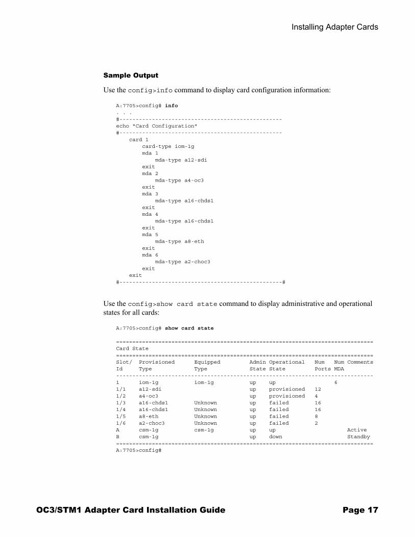
Sample Output
Use the config>info command to display card configuration information:
A:7705>config# info. . . #--------------------------------------------------echo "Card Configuration"#-------------------------------------------------- card 1 card-type iom-1g mda 1 mda-type a12-sdi exit mda 2 mda-type a4-oc3 exit mda 3 mda-type a16-chds1 exit mda 4 mda-type a16-chds1 exit mda 5 mda-type a8-eth exit mda 6 mda-type a2-choc3 exit exit#--------------------------------------------------#
Use the config>show card state command to display administrative and operational states for all cards:
A:7705>config# show card state
===============================================================================Card State===============================================================================Slot/ Provisioned Equipped Admin Operational Num Num CommentsId Type Type State State Ports MDA-------------------------------------------------------------------------------1 iom-1g iom-1g up up 61/1 a12-sdi up provisioned 121/2 a4-oc3 up provisioned 41/3 a16-chds1 Unknown up failed 161/4 a16-chds1 Unknown up failed 161/5 a8-eth Unknown up failed 81/6 a2-choc3 Unknown up failed 2A csm-1g csm-1g up up ActiveB csm-1g up down Standby===============================================================================A:7705>config#
OC3/STM1 Adapter Card Installation Guide Page 17

Installing Adapter Cards
Use the config>show mda command to display provisioned adapter card information:
A:7705>config# show mda
===============================================================================MDA Summary===============================================================================Slot Mda Provisioned Equipped Admin Operational Mda-type Mda-type State State-------------------------------------------------------------------------------1 1 a12-sdi up provisioned 2 a4-oc3 up provisioned 3 a16-chds1 Unknown up failed 4 a16-chds1 Unknown up failed 5 a8-eth Unknown up failed 6 a2-choc3 Unknown up failed===============================================================================A:7705>config#
Page 18 OC3/STM1 Adapter Card Installation Guide
Installing Adapter Cards
Installation Procedures
Warnings and Notes
Dangers: • Invisible laser radiation can be emitted from an adapter card’s port apertures when no
cable is connected. Avoid exposure and do not stare into open apertures.• Always assume that fiber-optic cables are connected to a light source.
Warnings: • Electrostatic discharge (ESD) damage can occur if adapter cards are mishandled. Always
wear an ESD-preventive wrist or ankle strap and always connect an ESD strap to a nearby ground point that is connected to the site grounding point when working with an adapter card. Typical ground points include the ground stud on the 7705 SAR-8 mounting bracket, or a properly grounded rack or work bench.
• Always place components on an anti-static surface.• Do not power up a 7705 SAR-8 before verifying that all common equipment (chassis,
power, cooling, and grounding) is connected properly.• Filler plates are required in all empty slots to prevent excess dust accumulation and to help
control airflow and electromagnetic interference.• Use only approved small form-factor pluggable (SFP) fiber-optic devices in adapter card
ports.• To comply with the GR-1089-CORE requirement R4-9 [31] standard for electromagnetic
compatibility and safety, all intra-building ports are specified for use with shielded and grounded cables at both ends.
• The intra-building port(s) of the equipment or sub-assembly is suitable for connection to intra-building or unexposed wiring or cabling only. The intra-building port(s) of the equipment or sub-assembly must not be metallically connected to interfaces that connect to the Outside Plant (OSP) or its wiring. These interfaces are designed for use as intra-building interfaces only (Type 2 ports as described in GR-1089-CORE) and require isolation from the exposed OSP cabling. The addition of primary protectors is not sufficient protection in order to connect these interfaces metallically to OSP wiring.
Notes: • Ports cannot be configured until the adapter card is provisioned.• Services cannot be provisioned until the ports are configured.• Adapter card slot numbers are MDA 1 through MDA 6.
OC3/STM1 Adapter Card Installation Guide Page 19

Installing Adapter Cards
Installing an Adapter CardA maximum of six 4-port OC3/STM1 Clear Channel Adapter cards or two 2-port OC3/STM1 Channelized Adapter cards may be installed on the 7705 SAR-8 in MDA slots 1 through 6. Figure 1 identifies the location of the MDA slots. Figure 2 illustrates the installation of an adapter card. Table 3 identifies the installation features. Ejector levers help install and remove the adapter card; captive screws secure the card in place.
Four SFP ports are supported on the 4-port OC3/STM1 Clear Channel Adapter card and two SFP ports are supported on the 2-port OC3/STM1 Channelized Adapter card for fiber or copper connectivity via SFP modules. Table 4 on page 28 lists the Alcatel-Lucent approved SFP modules supported by an OC3/STM1 Adapter card. For information on installing an SFP, see SFPs on page 25.
Refer to LED Descriptions on page 31 for information on the connectors and LEDs on the OC3/STM1 Adapter cards.
Figure 1: 7705 SAR-8 Slot Identification
Figure 2: Installing an Adapter Card
CSM A
MDA 1
MDA 3
MDA 5
CSM B
MDA 2FAN
Batt BMDA 4
MDA 6
Batt A
19635
A4-OC3Stat Port1 Port1Port2 Port1Port3 Port4
PwrMinor
Major
Critical
Batt B
Batt A
FanAlarm
ExternalAlarms
FAN
7705 SAR-8
CSM ASLOT ID
MDA 1MDA 3MDA 5
CSM BMDA 2MDA 4MDA 6
20140
4 3
3
21
4
Batt. A
-+
-+
Batt. B
Page 20 OC3/STM1 Adapter Card Installation Guide

Installing Adapter Cards
Tools required:
• torque driver for Phillips screws
To install an adapter card:
Step 1. Remove the adapter card from the packaging and place on an anti-static work surface. Avoid touching the card components and connector pins.
Step 2. Insert the adapter card into an empty MDA slot. With the ejector levers pressed inward, hold the adapter card by the levers and align the adapter card with the slot guides and the captive screws with the threaded receptacles (see Figure 2).
Step 3. Press the adapter card firmly into the slot. Make sure that the card connectors are fully seated in the backplane connectors.
Step 4. Tighten the captive screws to secure the card. Do not over-tighten. The recommended torque is 3 or 4 lbf.-in.
Step 5. Check the Power LED on the adapter card faceplate. If the adapter card is properly inserted and the 7705 SAR-8 has valid power, the Power LED is lit blue. See LED Descriptions on page 31 for a description of LED activity.
Step 6. Install any SFPs and attach cables. Refer to SFPs on page 25 for information on SFPs.
Removing and Replacing an Adapter CardIf you replace an adapter card with a different type, you must change the configuration to reflect the new adapter card type prior to removing the installed card. Each active port must be shut down before you shut down and remove an adapter card configuration (see Changing an Adapter Card Configuration for the required command steps). If you replace an adapter card with the same type, no configuration change is necessary. Refer to the 7705 SAR OS Interface Configuration Guide for details on configuring cards and ports.
If you are removing the card, but not replacing it, install a filler plate over the empty slot.
Table 3: Adapter Card Installation Features
Key Description
1 Slot guide
2 Threaded receptacle
3 Captive screw
4 Ejector lever
OC3/STM1 Adapter Card Installation Guide Page 21

Installing Adapter Cards
Changing an Adapter Card Configuration
In the example below, a 4-port OC3/STM1 Clear Channel Adapter card in slot 2 is replaced with a 2-port OC3/STM1 Channelized Adapter card.
Command Syntax Example
Step 1.port port-id port 1/2/1
Step 2.shutdown shutdown
Note: The port>shutdown command must be repeated for all enabled ports on theadapter card.
Step 3.exit exit
Step 4.card slot-number card 1
Step 5.mda mda-slot mda 2
Step 6.shutdown shutdown
Step 7.exit exit
Step 8.no mda mda-slot no mda 2
Step 9.mda mda-slot mda 2
Step 10.mda-type mda-type mda a2-choc3
Step 11.no shutdown no shutdown
Step 12.exit exit
Figure 3 illustrates removing an adapter card. Table 3 identifies the installation features.
Figure 3: Removing an Adapter Card
A4-OC3Stat Port1 Port1Port2 Port1Port3 Port4
PwrMinor
Major
Critical
Batt B
Batt A
FanAlarm
ExternalAlarms
FAN
7705 SAR-8
CSM ASLOT ID
MDA 1MDA 3MDA 5
CSM BMDA 2MDA 4MDA 6
20143
4 3
3
21
4
Batt. A
-+
-+
Batt. B
Page 22 OC3/STM1 Adapter Card Installation Guide
Installing Adapter Cards
Tools required:
• Phillips screwdriver• torque driver for Phillips screws
To remove and replace an adapter card:
Step 1. Disconnect all cable connections to the adapter card.Step 2. Use a Phillips screwdriver to loosen the captive screws.
Step 3. Simultaneously rotate both ejector levers outward to release the adapter card connectors from the backplane.
Step 4. Hold the adapter card by the ejector levers and pull the card out of the slot. Step 5. Place the adapter card on an anti-static surface.Step 6. Install a replacement adapter card in the slot or cover the slot with a filler plate.Step 7. Tighten the captive screws to secure the card or filler plate. Do not over-tighten. The
recommended torque is 3 or 4 lbf.-in.Step 8. If you replaced the adapter card, check the Power LED on the adapter card faceplate.
If the adapter card is properly inserted and the 7705 SAR-8 has valid power, the Power LED is lit blue. See LED Descriptions on page 31 for a description of LED activity.
Step 9. If you replaced the adapter card, reconnect all cable connections to the card.
Caution: Do not try to remove the adapter card from the slot before the captive screws are loosened.
OC3/STM1 Adapter Card Installation Guide Page 23

Installing Adapter Cards
Page 24 OC3/STM1 Adapter Card Installation Guide

SFPs
In This ChapterThis chapter provides information about installing and removing SFP transceivers on adapter card ports that support these devices.
This chapter provides information on the following topics:
• Installing and Removing SFPs on page 26→ Warnings and Notes on page 26→ Fiber Cable Preparation on page 27→ Locking Mechanisms on page 27→ Supported SFPs on page 28→ Installing SFPs on page 28→ Removing and Replacing SFPs on page 29
OC3/STM1 Adapter Card Installation Guide Page 25

SFPs
Installing and Removing SFPs
Warnings and Notes
Dangers: • Invisible laser radiation can be emitted from an adapter card’s or SFP’s port apertures
when no cable is connected. Avoid exposure and do not stare into open apertures.• Always assume that fiber-optic cables are connected to a light source.
Warnings: • Before using the optics on this adapter card, verify that the optical path is in compliance
with the parameters of the optical components. In particular, pay close attention to any minimum attenuation requirements for the optics. If minimum attenuation requirements are not met, the optical receiver components may be permanently damaged. Contact the appropriate technical support center for assistance and further information about your Alcatel-Lucent products.
• Ensure that the ports on an SFP are protected by an SFP protective plug when you install or remove an optical SFP. Only remove the plug when you are ready to install an SFP cable.
• Electrostatic discharge (ESD) damage can occur if adapter cards are mishandled. Always wear an ESD-preventive wrist or ankle strap and always connect an ESD strap to a nearby ground point that is connected to the site grounding point when working with an adapter card. Typical ground points include the ground stud on the 7705 SAR-8 mounting bracket, or a properly grounded rack or work bench.
• Always place router components on an anti-static surface.• Avoid bending a fiber cable beyond its minimum bend radius. Do not exceed the
recommended 1.2 inches (30 mm) for fiber-optic cables.
Cautions: • This is a Class 1 laser product. Only approved Class 1 replaceable laser transceivers
should be used on this product.• Ensure that the connector on the fiber cable is protected by a dust cover until you are
ready to attach the cable to an SFP. • The SFPs must have protective plugs if they are seated in the adapter card but are not
attached to fiber cables.• Always replace the dust cover on the connector of a fiber cable when the cable is
disconnected from an SFP.
Page 26 OC3/STM1 Adapter Card Installation Guide

SFPs
Fiber Cable PreparationClean the connector on the fiber cable before inserting it into the SFP to prevent transferring small particles and contaminating the transceiver.
If you switch SFPs from one port to another, ensure that you clean the fiber connectors before reinserting them.
Apply high standards when inspecting and cleaning fiber connectors. Use a “dry” cleaning method to clean fiber connectors.
Locking MechanismsSFPs approved by Alcatel-Lucent might use different lock and release methods. Possible lock and release mechanisms include:
• locking handle—a locking handle or lever on the front of the SFP that you gently raise or lower to insert or remove the SFP from the port
• bail—a bar or latch in the front of the SFP that you pull down and outward to release the module
• tabs—tabs on the sides or bottom of the SFP that you press inward to release the module
Notes:
• Discard SFPs according to all local laws and regulations.• SFPs can be installed and replaced without disabling the interfaces or removing the
adapter card from the 7705 SAR-8.• SFPs are keyed to prevent incorrect insertion. If an SFP is not seated properly, remove it
and confirm that the orientation is correct before reinserting it.
Caution: Improper handling, cleaning, and inspection techniques can compromise the fiber connection, resulting in data transmission errors. Refer to Alcatel-Lucent Online Customer Support (OLCS) (http://www.alcatel-lucent.com/myaccess), under the 7705 SAR documentation, for the Optical Handling Reference Guide (part number 95-5795-01-00).
OC3/STM1 Adapter Card Installation Guide Page 27

SFPs
Supported SFPsTable 4 lists the Alcatel-Lucent approved SFPs for the OC3/STM1 Adapter cards.
Installing SFPsTo install an SFP:
Step 1. Remove the SFP from the packaging and place it on an anti-static work surface.Step 2. Hold the SFP by its sides and insert it into the appropriate port until it clicks into
place.Step 3. Remove the protective plug from the SFP port when you are ready to attach the fiber
cable.
Table 4: SFPs for the OC3/STM1 Adapter Cards
Part Number
Short Description Media Wavelength Connector Type
Distance (1) Operating Temperature
3HE00034AA 1-port OC-3/STM-1 SONET/SDH Optics Module, multi-mode
Fiber 1310 nm LC Up to 2 km -40° to 85°C(-40° to 185°F)
3HE00035AA 1-port OC-3/STM-1 SONET/SDH Optics Module, intermediate reach
Fiber 1310 nm LC Up to 15 km -40° to 85°C(-40° to 185°F)
3HE00036AA 1-port OC-3/STM-1 SONET/SDH Optics Module, long reach
Fiber 1310 nm LC Up to 40 km -40° to 85°C(-40° to 185°F)
90-9764-04 STM1 Electrical Module
Copper N/A DIN Up to 120 m -40° to 85°C(-40° to 185°F)
Note:1. The distance values shown are for guidance only; the actual required distance will be determined by factors such as optical power levels and
attenuation.
Page 28 OC3/STM1 Adapter Card Installation Guide

SFPs
Removing and Replacing SFPsWhen you are replacing an SFP, have the following parts ready:
• a replacement SFP• protective plugs for the SFPs and a dust cover for the fiber cable connector• an anti-static mat or electrostatic bag
To replace an SFP:
Step 1. Disconnect the cable from the SFP connector.Step 2. Place a protective plug in the SFP that is being removed.Step 3. Release the locking mechanism on the SFP with your thumb and forefinger. See
Locking Mechanisms for descriptions of the different SFP lock and release methods. Slide the SFP out of the port.
Step 4. Place the SFP on an anti-static mat or in an electrostatic bag.Step 5. Install a replacement SFP into the adapter card port.Step 6. Connect the fiber or copper cable, or if you are not immediately connecting a fiber
cable, insert a protective plug into the SFP optical port and place a dust cover on the fiber cable connector.
Note: If you are not immediately replacing the SFP, leave the adapter card port empty. It is not necessary to install protective plugs in the ports on the adapter card.
OC3/STM1 Adapter Card Installation Guide Page 29

SFPs
Page 30 OC3/STM1 Adapter Card Installation Guide

LED Descriptions
In This ChapterThis chapter provides information on the following topic:
• OC3/STM1 Adapter Card LEDs on page 32
OC3/STM1 Adapter Card Installation Guide Page 31

LED Descriptions
OC3/STM1 Adapter Card LEDsFigure 4 shows the LEDs on the 4-port OC3/STM1 Clear Channel Adapter card. Figure 5 shows the LEDs on the 2-port OC3/STM1 Channelized Adapter card. Table 5 describes the faceplate LEDs for both cards.
Figure 4: 4-port Clear Channel OC3/STM1 Adapter Card LEDs
Figure 5: 2-port OC3/STM1 Channelized Adapter Card LEDs
A4-OC3Stat Port1 Port1Port2 Port1Port3 Port4
Pwr
1
2
3
20487
A2-CHOC3Stat Port1 Port1Port2
Pwr
1
2
3
20488
Page 32 OC3/STM1 Adapter Card Installation Guide

LED Descriptions
Table 5: OC3/STM1 Adapter Card LEDs
Key Label Description
1 Stat(us) Card status LED:Green (blinking): InitializingGreen (solid): Operationally up, administratively upAmber: Operationally down, administratively upUnlit: Operationally down, administratively down
2 Pwr Power status LED:Blue: Valid powerUnlit: No power or faulty power
3 Port1 Port2 Port3 Port4 Port numbers (ports 1 to 4 on the 4-port OC3/STM1 Clear Channel Adapter card, ports 1 and 2 on the 2-port OC3/STM1 Channelized Adapter card) and corresponding LEDs, as follows:Green: Valid communication link establishedUnlit: Port is disabled or shut downAmber (blinking): No SFP or port loopbackAmber: No link
OC3/STM1 Adapter Card Installation Guide Page 33

LED Descriptions
Page 34 OC3/STM1 Adapter Card Installation Guide

Customer documentation and product support
Customer documentationhttp://www.alcatel-lucent.com/myaccessProduct manuals and documentation updates are available at alcatel-lucent.com. If you are a new user and require access to this service, please contact your Alcatel-Lucent sales representative.
Technical Supporthttp://www.alcatel-lucent.com/support
Documentation [email protected]

© 2009 Alcatel-Lucent. All rights reserved.3HE 04952 AAAA TQZZA Edition 01