alan hp106 / alan hp406 manual
TRANSCRIPT

T h e W o r l d i n C o m m u n i c a t i o n
®
Prodotto o importato da:CTE INTERNATIONAL s.r.l.Via. R.Sevardi 7- 42010 MancasaleReggio Emilia ItaliaL’uso di questo apparato può esseresoggetto a restrizioni nazionali.Prima dell'uso leggere attentamente leistruzioni. Se il prodotto contiene batterie:non gettare nel fuoco, non disperderenell’ambiente dopo l’uso, usare gli appositicontenitori per la raccolta.
Produced or imported by:CTE INTERNATIONAL s.r.l.Via. R.Sevardi 7 - 42010 MancasaleReggio Emilia Italy
ALAN UKUnit 2, Callenders, Paddington Drive,Churchward Park, Swindon, Wiltshire, SN57YW United Kingdom
The use of this transceiver can be subjectto national restrictions. Read theinstructions carefully before installationand use. If the product contains dry cellsor rechargeable batteries do not throw thebatteries into the fire. To disperse afteruse, throw into the appropriate containers.
Producido o importado por:ALAN COMMUNICATIONS, S.A.C/Cobalto, 48 - 08940 Cornellà DeLlobregat - España Tel 902 38 48 78El uso de este equipo está sujeto a laobtención de la correspondienteautorización administrativa. Antes deutilizar, lea atentamente el manual de uso.Si el producto contiene pilas o baterias:no las tire al fuego ni las disperse en elambiente después de su uso, utilice loscontenedores especiales para su recogida.
Herstellung/Vertrieb durch:ALAN ELECTRONICS GmbHDaimlerstraße 1KD-63303 Dreieich DeutschlandDie Benutzung dieses Handfunkgerätesist von den landesspezifischenBestimmungen abhängig.Vor Benutzung Bedienungsanleitungbeachten. Bei Verwendung von Batterienbeachten Sie bitte dieUmweltbestimmungen. Batterien niemalsins offene Feuer werfen und nur in dendafür vorgesehenen Sammelbehälterentsorgen.
D
T h e W o r l d i n C o m m u n i c a t i o n
Alan HP 106 (VHF)
Alan HP 406 (UHF)
Manuale d'usoUser's manualManuel d’utilisationBedienungsanleitungManual del usuarioManuale do utilizador
I
GB
P
F
E
5
6
1 2
3 4
11
12
7
8
10 9
Diritto d'autore 2003 della CTE International Italia; tutti i diritti riservati.Copyright 2003 by CTE International Italy; all rights reserved.
Les droits d’auteur © 2003 par CTE International Italie; tous droits réservés.Copyright 2003 by CTE International Italy; alle Rechte vorbehalten.
Derechos del autor 2003 de CTE International Italia; todos los derechos reservados.Direito de autor 2003 de CTE International Italia; todos os direitos são reservados.

English
ISTR106_int 26-09-2003 9:47 Pagina 23
In this book... 1
1 ALAN HP106/HP406 – THE POWER OF SIMPLICITY 3
2 SAFETY FIRST 42.1 Conventions and Symbols in this Book 42.2 Warning notes 42.3 Safety 5
3 PART NAMES AND THEIR FUNCTIONS 63.1 Top 63.2 Front 73.3 Side (left and right) 7
4 SETUP 84.1 Unpacking 84.2 Fitting/removing the antenna 84.3 Installing/removing the battery pack 94.4 Installing/removing the belt clip 94.5 Charging the battery pack 10
5 BASIC OPERATIONS 105.1 Switching the radio ON/OFF 105.2 Adjusting volume 115.3 Channel selection 115.4 Reception 115.5 Monitor 125.6 Transmission 12
5.6.a Time-out Transmission Timer (TOT) 125.6.b Busy Channel Lock Out 135.6.c Transmission Power 13
6 CTCSS/DCS AND SELECTIVE CALL OPERATION 146.1 Reception 146.2 Transmission 14
6.2.a CTCSS/DCS transmission 146.2.b Sending a normal selective call 146.2.c Sending an emergency selective call 14
7 ADVANCED OPERATIONS 157.1 Channel Scanning 15
7.1.a Enabling/disabling scanning 157.1.b Priority Channel 15
7.2 Handsfree transmission (VOX) 167.2.a Headset Connection 167.2.b Enabling/disabling VOX 167.2.c Adjusting VOX sensitivity 16
7.3 Confidential Communications (scrambler) 16
8 CARE AND MAINTENANCE 178.1 Battery Packs 17
8.1.a Properly charging battery packs 178.1.b Memory effect 188.1.c Erasing memory effect 188.1.d Warnings for battery and chargers use 18
8.2 Radio maintenance 198.2.a Cleaning the radio 198.2.b Cleaning battery packs 198.2.c Connectors 19
Eng
lish
ISTR106_int 26-09-2003 9:47 Pagina 1
2 In this book
9 OPTIONAL ACCESSORIES 209.1 Microphone/speaker or Headset with microphone 20
9.1.a Contacts layout 209.1.b Connection 20
10 QUICK REFERENCE 2110.1 Operation resume 21
11 TECHNICAL SPECIFICATIONS 2211.1 Test methods 2211.2 Specifications table 22
Eng
lish
ISTR106_int 26-09-2003 9:47 Pagina 2
ALAN HP106/HP406 - The power of semplicity 3
1 ALAN HP106/HP 406 – The power of semplicity
Congratulations. ALAN HP106/HP406 is a Professional Radio, whoserugged design allows it to be your reliable partner even during hard wor-king days.It’s a transceiver designed to be easy to use, but featured with advancedfunctions that make it flexible to every use. We state the most important ones:
• Easy to use – just only five commands to control all the transceiver’sfunctions.
• Channel scanning – it allows to automatically search the radiosignals on the programmed channels.
• VOX (Voice Operated eXchange) – it allows to enable the transmis-sion by simply speaking, in full handsfree condition, by the optionalheadset/microphone.
• CTCSS/DCS – to share more radio networks on the same frequencyand safely access to your radio repeaters.
• Selective call – for more advanced radio network management. Youcan individually call a user inside a network or make group calls.
• Emergency selective call – you can send it, when needed, with asimple command protected against accidental switching.
• Analogue scrambler – for confidential communications. Radio com-munications are encoded and decoded from every ALAN HP106 inorder to reduce the risk of tapping from third parties who are watchingyour frequency.
• Wide range of optional accessories which allow to extend the flexi-bility of use.
Transceiver’s specifications of ALAN HP106/HP4065 are compliantwith ETS 300 086, moreover its top level design and resistance arecompliant with IEC529 level IP54 and MIL STD 810 C,D,E.
CTE International is committed to continuous quality improve, for thisreason specifications may vary without prior notice.
Eng
lish
ISTR106_int 26-09-2003 9:47 Pagina 3
4 Safety first
2 Safety first
2.1 Conventions and Symbols in this Book
This symbol marks a ‘note’. Notes are hints or tips which offer addi-tional information to allow an easier use of the device and obtain thebest performances.
This symbol marks a ‘caution’. Cautions are special noticeswhich you should read and follow carefully to avoid possibledamage to your equipment and to avoid potential danger toyourself or other people.
Key names will be highlighted in bold.Important sentences and words are highlighted in Italic.
2.2 Warning notes
Every effort has been made to ensure that the information in thisdocument is complete, accurate and up-to-date. CTEInternational assumes no responsibility for the results of errorsbeyond its control. The manufacturer of this equipment also can-not guarantee that changes in the equipment made by nonauthorized people will not affect the applicability of the informa-tion in it.The operations described in this manual should be executed fol-lowing the order they are listed. The consultation references ofthe chapters/paragraphs are exclusively listed to allow a morepractical use.
The reliability of what is described in this manual is intendederrors and omissions expected. In case of any doubts pleasecontact your dealer/radio network manager.
Eng
lish
ISTR106_int 26-09-2003 9:47 Pagina 4
Safety first 5
2.3 Safety
Your ALAN HP106/HP406 handheld transceiver has been carefully desi-gned to give you years of safe, reliable performance. As with all electricalequipments, however, there are a few basic precautions you should taketo avoid hurting yourself or damaging the radio:
Read the instructions in this handbook carefully. Be sure to saveit for future reference.Read and follow all the warning labels and instruction on theradio itself and on the accessories.Don’t carry the transceiver by the antenna. This may damage theantenna or antenna terminal. Grasp it by its base (not the tip!)when you need to place or remove it.Don’t keep the radio with the antenna very close to you, or tou-ching exposed parts of the body, while transmitting. The radiowill perform best if the microphone is 5-10 cm away from themouth and the radio is vertical.Be sure the PTT key is not accidentally depressed when youdon’t need to transmit.Do not operate the radio near unshielded electrical blasting capsor in an explosive atmosphere.Don’t transmit without the antenna fitted on the radio or with adamaged antenna. Though it is provided with a protection, it mayseriously damage the TX output final stage.Respect the environment conditions. The radio is designed to beused in heavy environments, however avoid exposing it to extre-mely hot or cold temperature (out of the range between –30° to+60°C). Don’t expose the transceiver to excessive vibrations aswell as dusty or rainy places.
Never try to disassemble or service the radio by yourself (asidefrom the routine maintenance described in this handbook). It willimmediately void the warranty and you may cause damagerequiring extensive repair work. Always contact your local dealerfor assistance.Grasp your radios firmly. Otherwise it may fall and be damaged.Use only genuine accessories. Non original ones could seriouslydamage your handheld transceiver.Do not use your radio near water or spill liquid of any kind into it.If the transceiver gets wet immediately, dry it by a soft and cleancloth.Switch the radio off before you clean it. Strictly follow the direc-tions stated in Chapter 8.Handle the battery properly. Strictly follow the directions statedin Chapter 8.Be certain that your power source matches the rating listed forthe supplied battery charger. If you are not sure, check with yourdealer or with your local power company.To avoid damaging the power cable of the battery charger, donot put anything on it or place it where it will be walked on.
This product complies with the requirements of the Council Directives89/336/EEC and 73/23/EEC on the approximation of the laws of themember states relating to electromagnetic compatibility and low voltage.
Eng
lish
ISTR106_int 26-09-2003 9:47 Pagina 5
6 Part names and their functions
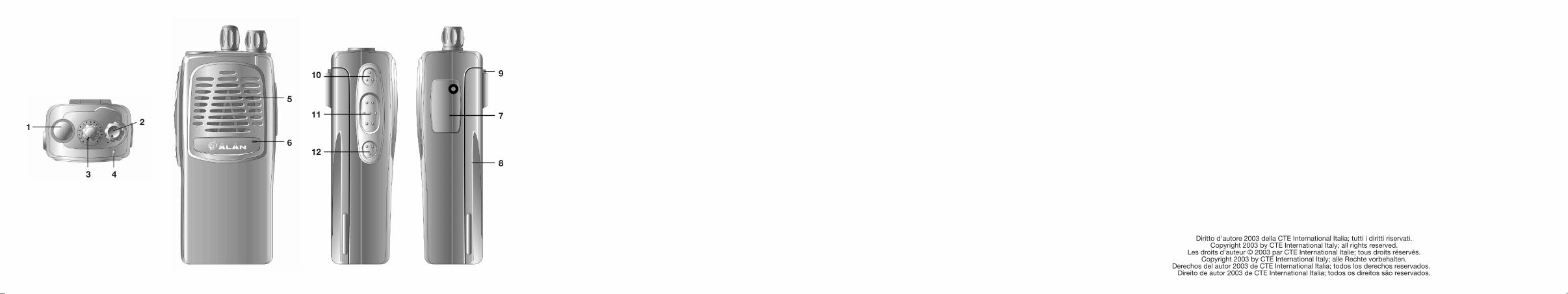
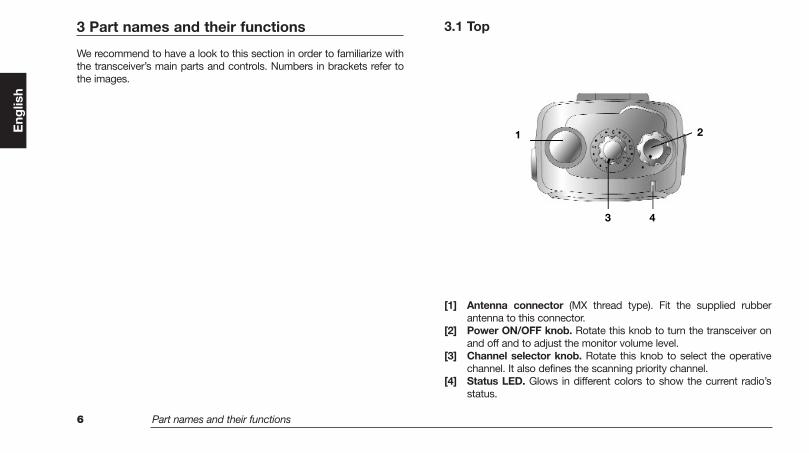
3 Part names and their functions
We recommend to have a look to this section in order to familiarize withthe transceiver’s main parts and controls. Numbers in brackets refer tothe images.
3.1 Top
[1] Antenna connector (MX thread type). Fit the supplied rubberantenna to this connector.
[2] Power ON/OFF knob. Rotate this knob to turn the transceiver onand off and to adjust the monitor volume level.
[3] Channel selector knob. Rotate this knob to select the operativechannel. It also defines the scanning priority channel.
[4] Status LED. Glows in different colors to show the current radio’sstatus.
Eng
lish
1
3 4
2
ISTR106_int 26-09-2003 9:47 Pagina 6
Part names and their functions 7
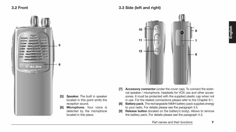
3.2 Front
[5] Speaker. The built in speakerlocated in this point emits thereception sound.
[6] Microphone. Your voice isdetected by the microphonelocated in this place.
3.3 Side (left and right)
[7] Accessory connector (under the cover cap). To connect the exter-nal speaker / microphone, headsets for VOX use and other acces-sories. It must be protected with the supplied plastic cap when notin use. For the related connections please refer to the Chapter 9.1.
[8] Battery pack. The rechargeable NiMH battery pack supplies energyto your radio. For details please see the paragraph 4.5.
[9] Release button (located on the battery’s body). Allows to removethe battery pack. For details please see the paragraph 4.3.
Eng
lish
5
6
10
11
12
9
7
8
ISTR106_int 26-09-2003 9:47 Pagina 7
8 Setup
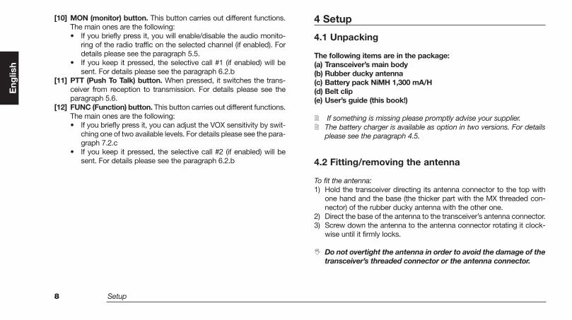
[10] MON (monitor) button. This button carries out different functions.The main ones are the following:• If you briefly press it, you will enable/disable the audio monito-
ring of the radio traffic on the selected channel (if enabled). Fordetails please see the paragraph 5.5.
• If you keep it pressed, the selective call #1 (if enabled) will besent. For details please see the paragraph 6.2.b
[11] PTT (Push To Talk) button. When pressed, it switches the trans-ceiver from reception to transmission. For details please see theparagraph 5.6.
[12] FUNC (Function) button. This button carries out different functions.The main ones are the following:• If you briefly press it, you can adjust the VOX sensitivity by swit-
ching one of two available levels. For details please see the para-graph 7.2.c
• If you keep it pressed, the selective call #2 (if enabled) will besent. For details please see the paragraph 6.2.b
4 Setup
4.1 Unpacking
The following items are in the package:(a) Transceiver’s main body(b) Rubber ducky antenna(c) Battery pack NiMH 1,300 mA/H(d) Belt clip(e) User’s guide (this book!)
If something is missing please promptly advise your supplier.The battery charger is available as option in two versions. For detailsplease see the paragraph 4.5.
4.2 Fitting/removing the antenna
To fit the antenna: 1) Hold the transceiver directing its antenna connector to the top with
one hand and the base (the thicker part with the MX threaded con-nector) of the rubber ducky antenna with the other one.
2) Direct the base of the antenna to the transceiver’s antenna connector.3) Screw down the antenna to the antenna connector rotating it clock-
wise until it firmly locks.
Do not overtight the antenna in order to avoid the damage of thetransceiver’s threaded connector or the antenna connector.
Eng
lish
ISTR106_int 26-09-2003 9:47 Pagina 8
Setup 9
To remove the antenna:1) Execute the above-mentioned step 1.2) Unscrew the rubber ducky antenna rotating it counterclockwise and
remove it.
Leave the antenna fitted on the radio. You can’t communicatewithout it. Moreover, transmitting without the antenna (or with adamaged antenna) may damage the TX output final stage. Usethe supplied antenna only.The supplied antenna is broadband type and covers the whole spec-trum, so it doesn’t need any alignment procedure.
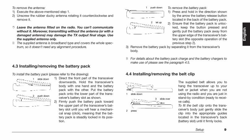
4.3 Installing/removing the battery pack
To install the battery pack (please refer to the drawing):1) Direct the front part of the transceiver
downwards. Hold the transceiver’sbody with one hand and the batterypack with the other. Put the batterypack onto the lower part of the trans-ceiver’s battery slot as shown.
2) Firmly push the battery pack towardthe upper part of the transceiver’s bat-tery slot until you will hear a mechani-cal snap (click), meaning that the bat-tery pack is steadily locked in its posi-tion.
To remove the battery pack:1) Press and hold in the direction shown
by the arrow the battery release buttonlocated in the back of the battery pack.
2) Ensure that the battery pack is unloc-ked, keep the button pressed andgently pull the battery pack away fromthe upper edge of the transceiver’s bat-tery slot (the opposite operation of theprevious step 2).
3) Remove the battery pack by separating it from the transceiver’sbody.
For details about the battery pack charge and the battery chargers tomake use of please see the paragraph 4.5.
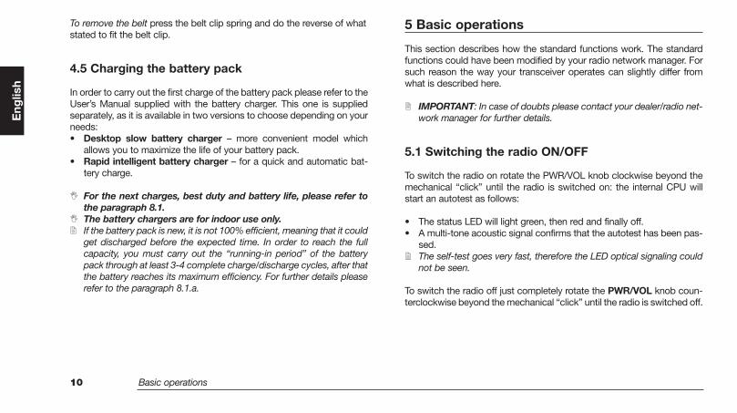
4.4 Installing/removing the belt clip
The supplied belt allows you tohang the transceiver up to yourbelt or jacket when you are notusing the radio and you are just instand-by condition (ready to recei-ve calls).To fit the belt clip onto the trans-ceiver’s body just gently slide theclip into the appropriate guideslocated in the transceiver’s back(battery slot) until it firmly locks.
Eng
lish
1 slide down
2 push down
1 push down
2 let up
1 slide down
3 slide over
2 press
ISTR106_int 26-09-2003 9:47 Pagina 9
10 Basic operations
To remove the belt press the belt clip spring and do the reverse of whatstated to fit the belt clip.
4.5 Charging the battery pack
In order to carry out the first charge of the battery pack please refer to theUser’s Manual supplied with the battery charger. This one is suppliedseparately, as it is available in two versions to choose depending on yourneeds:• Desktop slow battery charger – more convenient model which
allows you to maximize the life of your battery pack.• Rapid intelligent battery charger – for a quick and automatic bat-
tery charge.
For the next charges, best duty and battery life, please refer tothe paragraph 8.1.The battery chargers are for indoor use only.If the battery pack is new, it is not 100% efficient, meaning that it couldget discharged before the expected time. In order to reach the fullcapacity, you must carry out the “running-in period” of the batterypack through at least 3-4 complete charge/discharge cycles, after thatthe battery reaches its maximum efficiency. For further details pleaserefer to the paragraph 8.1.a.
5 Basic operations
This section describes how the standard functions work. The standardfunctions could have been modified by your radio network manager. Forsuch reason the way your transceiver operates can slightly differ fromwhat is described here.
IMPORTANT: In case of doubts please contact your dealer/radio net-work manager for further details.
5.1 Switching the radio ON/OFF
To switch the radio on rotate the PWR/VOL knob clockwise beyond themechanical “click” until the radio is switched on: the internal CPU willstart an autotest as follows:
• The status LED will light green, then red and finally off.• A multi-tone acoustic signal confirms that the autotest has been pas-
sed.The self-test goes very fast, therefore the LED optical signaling couldnot be seen.
To switch the radio off just completely rotate the PWR/VOL knob coun-terclockwise beyond the mechanical “click” until the radio is switched off.
Eng
lish
ISTR106_int 26-09-2003 9:47 Pagina 10
Basic operations 11
5.2 Adjusting volume
With the device turned on, rotate the PWR/VOL knob clockwise toincrease the volume or counterclockwise to reduce it. For a normal usewe suggest to keep it to the middle position.
5.3 Channel selection
If your radio has been programmed with more than one channel you caneasily change it. To select a channel, turn the channel selector knobclockwise or counterclockwise until the channel indicator on the knobmatches the wished channel. If the selected channel has not previously been programmed, the greenstatus LED remains permanently lit and a low error tone is produced.
5.4 Reception
Your radio could have been previously programmed to work, channel bychannel, in different modes: Open traffic, CTCSS/DCS or SelectiveCall. Please have a look to each description and ask your radio networkmanager or dealer which mode your radio channels have been program-med.• OPEN TRAFFIC - in this mode you will hear any communication
which will be transmitted on the selected channel. When no signalsare received, the circuit called Squelch will mute the audio of yourdevice in order to not let you hear the annoying background noise.When the signals are received, the squelch will open (i.e. it will auto-matically disabled), the status LED will glow green and you will hear
the message from the speaker. At the end of message the squelch willshut automatically.
• CTCSS/DCS (Continuous Tone Code Squelch System - DigitalCoded Squelch) - they are systems which use particular TX signaling(a continuous sub-audio tone for CTCSS or a digital sub-audio codefor DCS, both transmitted below the audio band, so not audible) asan access “key” to work a repeater or to unlock the party’s squelch,which is sensitive to this signaling only. This last condition allows toshare more radio networks on the same frequency. In this case youwill receive only messages coming from parties sending a proper TXsignaling, i.e. belonging to your group. During CTCSS/DCS operation,only the reception of the appropriate CTCSS/DCS tone/code enablesthe speaker, glowing amber the status LED. Eventual signals withoutthe appropriate CTCSS/DCS tone will leave the speaker muted andwill glow green the status LED. For further details please refer to thechapter 6.
• SELECTIVE CALL: It is a signalling system which uses audio tonesin sequence (usually “5 tones” selective calls) to call a specific stationor group(s). In this case you will only receive calls that have yourselective call identification code (a number) or calls sent to the groupyou belong. For further details please refer to the chapter 6.
CTCSS/DCS and Selective Call can be combined together.CTCSS/DCS and Selective Call allow to share the same frequencyamong more than one radio network, however they are just usefulto avoid disturbing stations not owning of the same network withmessages not related to them. In any case, if more than one sta-tion is transmitting at the same time on the same channel, this willcause interferences. Don’t transmit if the status LED is glowinggreen or amber. Wait till nobody is transmitting on the channel.
Eng
lish
ISTR106_int 26-09-2003 9:47 Pagina 11
12 Basic operations
5.5 Monitor
The MON (monitor) button is mainly useful for two purposes:• If the channel you have tuned has been programmed in the Open
Traffic mode, briefly pressing the MON button temporarily disablesthe squelch in order to allow you the reception of extremely weaksignals that can’t steadily open the squelch and are therefore recei-ved “chopped”.
• If the channel you have tuned has been programmed withCTCSS/DCS and/or Selective Call, a brief pressure of the MON but-ton temporarily disables the CTCSS/DCS and/or Selective Call toallow you to monitor all the communications on the tuned channel,even the ones that are not belonging to your network. Practically, youare able to temporarily receive in Open Traffic just briefly pressing theMON button.In any case, if the MON button is enabled on your transceiver, pressit briefly to temporarily monitor the signals on the tuned channel andrepeat this operation to return to the normal condition.
Every time the MON button is pressed, a high or low acoustic tone willbe produced to notify respectively the monitor function enabled (opensquelch or disabled CSCSS/selective call) or disabled (closed squelchor enabled CSCSS/selective call)Depending on the programming, the MON button could not be acti-ve or work in order to disable the CTCSS/DCS only or the selectivecall only. Please refer to your dealer/radio network manager for details.
5.6 Transmission
To transmit please follow this procedure:1) Ensure that the channel is not busy (otherwise you will create an inter-
ference), verifying that the status LED is not glowing green or amber.If the channel is not free, please wait until that condition (LED turnedoff)
2) Keep pressed the PTT button and verify that the status LED is glo-wing red to show that you are transmitting.
3) Speak with a normal voice level at approximately 5-10 cm from themicrophone.
4) When your message is over, release the PTT button ensuring that thestatus LED is turned off.
Don’t shout! It won’t increase the distance range, but rather will makeyou heard distorted.Don’t release the PTT button before your message is over or start tal-king before pressing it, otherwise your message will be “chopped”.”A handheld radio doesn’t normally allow to talk and receive simulta-neously, for this reason make your messages with a reasonable time.When you are talking, the other parties can’t do that, so don’t occupytoo much the channel.In order to transmit properly, please also see the following paragraphs.
5.6.a Time-out Transmission Timer (TOT)The radio might be programmed with the internal TOT timer (Time OutTimer) which automatically put your radio in reception if you talk too long(after a preset time). In this case release the PTT button and wait for fewseconds: the radio TX features will be automatically restored. Ask thenetwork responsible or your dealer for further details.
Eng
lish
ISTR106_int 26-09-2003 9:47 Pagina 12
Basic operations 13
5.6.b Busy Channel Lock OutThe radio might be programmed with the Busy Channel Lock Out(BCLO). In this condition the PTT button is disabled during the receptionof radio signals. For such reason, if you are not able to transmit while youare pressing the PTT button (the status LED is not glowing red), releasethe PTT button and verify if the channel is actually free (the status LED isturned off).
Depending on the programming, the BCLO can work either when itfinds any signal or in case of a signal with a specific CTCSS/DCSsignaling.
5.6.c Transmission PowerYour ALAN HP106/HP406 can transmit with two power levels accordingto the distance of your party station(s). The low/high power channels arepreset during the programming and cannot be modified by the user. Westrongly recommend to use low power when possible: you will extend thelife of the battery and you will reduce the risk of interference with stationsnot belonging to your radio network which could share with you the samechannel.
In case of low battery level, the unit will then automatically revert tolow power in order to help to extend the battery's operational life. Inthis case, two short beeps (acoustic signals) will be heard beforetransmission and one during reception.
Eng
lish
ISTR106_int 26-09-2003 9:47 Pagina 13
14 CTCSS/DCS and Selective Call operation
6 CTCSS/DCS and Selective Call operation
6.1 Reception
The radio may be set-up so that, during the operation with theCTCSS/DCS and/or Selective Call, audio is enabled only when you recei-ve the appropriate CTCSS/DCS tone and/or Selective Call. Speaker willthen remain muted until the correct CTCSS tone, the correct DCS codeand/or the appropriate selective call is received. As soon as this condi-tion takes place, the speaker will be unmuted allowing you to hear themessage and the status LED will glow amber. In case of reception ofsignals without the correct tone, the speaker will remain muted and thestatus LED will glow green.
Depending on the programming, you can temporarily disable theCTCSS/DCS and the selective call in order to monitor the radio traf-fic. For details please refer to the paragraph 5.5.
6.2 Transmission
6.2.a CTCSS/DCS transmission If your transceiver has been programmed to transmit a CTCSS tone or aDCS code, it is not necessary to do anything. The CTCSS tone or theDCS code is automatically sent every time you transmit (the device doesnot show this condition).
6.2.b Sending a normal selective callOn your transceiver the MON and FUNC buttons could have been pro-grammed to send, respectively, the selective call Nr.1 and Nr.2.
To send a selective call:1) Ensure that the channel is not busy (otherwise you will cause an inter-
ference), verifying that the status LED is not glowing green or amber.If the channel is not free, please wait until that condition takes place(LED turned-off)
2) Keep the MON or FUNC button pressed until the device will producea beep (about 3 seconds), then release the button. The defaultaddress of every button is automatically recalled.
During a call, the transceiver turns automatically on the transmission(the status LED glows red), so it is not necessary to press the PTT but-ton.
6.2.c Sending an emergency selective callIf your transceiver has been programmed to send an emergency selecti-ve call, you can send it by simultaneously pressing for a long time boththe MON and FUNC buttons until you will hear a beep and the statusLED will glow red, then release the buttons. The transceiver will send theemergency selective call.
Please use the emergency selective call only if a real conditionrequires its use. Please agree its use with your radio networkmanager.During a call the transceiver turns automatically on the transmission(the status LED glows red), so it is not necessary to press the PTT but-ton
Eng
lish
ISTR106_int 26-09-2003 9:47 Pagina 14
Advanced operations 15
7 Advanced operations
In this section we’ll describe some advanced operations which you cando with your handheld transceiver.
7.1 Channel Scanning
If you have more than one channel programmed, your ALANHP106/HP406 can scan them; in other words it can repeatedly switchthrough all the programmed channels cyclically and automatically stopwhen a signal is detected on one of them. During the scanning, only thechannels belonging to a specific scanning list (defined by the set-up) aremonitored. If a valid signal is received during the scanning, the scanningstops and the communication is audible through the speaker. When thesignal is over, the scanning automatically restarts.If the CTCSS/DCS or the selective call have been previously program-med, the device could be set-up to stop only if the received signals con-tain the correct signaling.
7.1.a Enabling/disabling scanningTo enable the scanning:1) Turn off the device2) Turn on the device keeping the MON + FUNC button pressed. A high
beep (after the acoustic tone of power-on confirmation stated in theparagraph 5.1) notifies that the scanning is activated, and the statusLED will slowly blink amber.
During scanning the channel selector knob becomes invalid.If the Scan List is empty, an error tone will be heard when you try to
activate the scan and the radio will not start the Scan Mode.Obviously, at least two channels must be entered in the Scan List forthe unit to be put in the SCAN Mode.If the PTT button is pressed during the channel scanning, this one willstop and the radio will transmit on the first vacant channel, then theunit will automatically resume scanning.
To stop the scanning, repeat the above procedure from step 1. A lowbeep is produced and the scanning will stop.
7.1.b Priority Channel Depending on the transceiver’s programming, one of the scanning listchannels could have been assigned as Priority Channel. The scanningwill monitor the priority channel more frequently.The programming could has been also set-up to allow you to decide,from time to time, which is the channel to assign as priority. For informa-tion please contact your dealer/radio network manager.To assign a priority channel (if previously enabled by the programming):1) Ensure that the scanning is not active.2) Before starting the scan mode, select the desired channel using the
channel selector.3) Start the channel scanning as described in paragraph 7.1.a. The
channel previously selected by the channel selector will be scannedmore frequently.
Once the scanning is started, if you wish to change the priority chan-nel, you need to disable the scanning. Therefore it is not sufficient toturn-off the device, rotate the channel selector, and switch it on again.Depending on the programming, on the priority channel could also beset the busy channel lock out function (BCLO) or other conditions (i.e.
Eng
lish
ISTR106_int 26-09-2003 9:47 Pagina 15
16 Advanced operations
reception of a correct CTCSS/DCS signal, with CTCSS/DCS incor-rect, etc.). For details about the BCLO operation please refer to theparagraph 5.6.b
7.2 Handsfree transmission (VOX)
VOX (Voice Operated eXchange) is a device that allows you to automati-cally switch the transmission in hands free mode just by speaking in thebuilt-in microphone of a headset (not provided with the unit) connectedto your transceiver. Once you have finished to talk, the VOX automaticallyswitches the radio on reception.
Ensure that the headset with microphone you are going to use issuitable to your transceiver as stated in the paragraph 9.1
7.2.a Headset Connection1) With a suitable screwdriver, unscrew the screw that holds the cover
cap of the accessory connector (item [7] of the paragraph 3.3)2) Keep the cover cap in a safe place and connect the headset/micro-
phone to the accessory connector (for details about the contactslayout please refer to the paragraph 9.1.a).
In order to avoid damages to the device, put the cover cap in itsplace again when the accessory connector is not used.
7.2.b Enabling/disabling VOX1) Ensure that the headset is properly connected and that the headset’s
built-in microphone is located close to the side of your mouth.2) Switch on the radio on keeping pressed the FUNC button.
3) When the device is switched on, release the button.
7.2.c Adjusting VOX sensitivity1) Enable the VOX as described above2) Briefly press the FUNC button to select one of two VOX sensitivity
levels (high/low).3) Perform some tests in order to ensure a stable transmission when
speaking with a normal voice level, but avoiding accidental transmis-sions.We recommend to set just the minimum sensitivity as possible.A too high value could cause accidental transmissions, espe-cially in hi-noise environments.The transceiver isn’t provided with any indication of LOW/HIGH VOXsensitivityPTT button is disabled during VOX operation.
7.3 Confidential Communications (scrambler)
Your transceiver could have been programmed to use the scramblerwhen necessary. This is a device that make your communications unin-telligible to normal receivers/transceivers, but perfectly clear to the otherradios of your network, that obviously must belong to the HPx06 family(i.e. equipped of the same type of scrambler).To enable the scrambler:1) Ensure that the other party enables his/her scrambler too.2) Simultaneously and briefly press the MON and FUNC buttons. The
device will send a high-pitched beep to confirm that the scrambler isenabled.
To disable the scrambler:
Eng
lish
ISTR106_int 26-09-2003 9:47 Pagina 16
Care and maintenance 17
1) Ensure that the other party disables his scrambler too2) Follow the above-mentioned step 2. The device will produce a low-
pitched beep to confirm that the scrambler is disabled.
If the scrambler is enabled, you can’t receive unencrypted communi-cations. In any case, in order to guarantee the communication, all theradios that have to communicate each other must have the scramblerenabled or disabled.The scrambler can be disabled during the programming. In case ofdoubts please contact your dealer/radio network manager.As any coding device, even your transceiver’s scrambler cannot gua-rantee the communication security at 100%.
8 Care and maintenance
8.1 Battery Packs
8.1.a Properly charging battery packs Should you properly use the battery pack, you will obtain at least 400charging/discharging cycles with an excellent working life. To properlycharge the battery pack:1) Ensure that the radio is switched off.2) Insert the radio (or the battery pack) into the cradle as explained in the
paragraph 4.5.3) Wait the necessary time to provide a full charge.
Don’t overcharge the battery: always remember to remove theradio after the necessary time.The battery charger is for indoor use only.When possible, charge the battery when it is fully discharged or, atleast, you have used it for the major part of its duty; otherwise the bat-tery’s duty could be temporarily reduced. Please see the paragraph8.1.b.Don’t remove the radio before the necessary time, otherwise the bat-tery’s duty could be temporarily reduced. Please see the paragraph8.1.b.Rechargeable battery packs lose their charge with the time if left unu-sed (self-discharge): this is normal. A NiMH (Nickel Metal Hydrate) bat-tery can reduce 10 to 20% of its stored energy in a few days.It is normal that the battery duty will progressively reduce after 2/3 ofits life (approx.).
Eng
lish
ISTR106_int 26-09-2003 9:47 Pagina 17
18 Care and maintenance
8.1.b Memory effect The supplied NiMH (Nickel Metal Hydrate) battery pack is made with amore advanced technology than normal NiCd (Nickel Cadmium) battery.For this reason it is virtually free of what is called “memory effect”, that isa temporary capacity reduction which reduces the battery duty Memoryeffect may occur just if you regularly charge the battery when you have-n’t discharged it at least at 50-70%. Memory effect can be easily avoidedby following these simple rules:• When possible charge battery packs only when they are completely
discharged.• Don’t remove the battery from the charger before the necessary time
to provide a full charge.• Provide at least two deep charge/discharge cycles per month.• The best way to avoid memory effect is to use two battery packs and
alternate their use with the radio. This will allow you to keep on yourtransceiver’s operation by replacing the battery pack just when it’sfully discharged and use the spare (charged) one.
8.1.c Erasing memory effect Memory effect can be easily erased just by applying 3-4 deeper char-ge/discharge cycles.1) Use the battery fitted in the radio and wait till the radio switches off for
a lack of energy, then switch the radio off by the PWR/VOL knob.2) Wait at least one hour and then try to switch on the radio: you will note
that some energy has restored in the battery, because the radio canbe switched on.
3) Leave the radio in RX until the radio switches off again, then switch itoff by the PWR/VOL knob.
4) Repeat steps 2) and 3) three times.5) Fully charge the battery and check the battery duty. If some memory
effect still exists, go back to step 1.
If the battery duty does not improve after three of the over statedcycles, it means that your battery pack is faulty or has reached the endof life (please refer to the paragraph 8.1). In this case please ask yourdealer to provide you with a new battery pack.
8.1.d Warnings for battery and chargers usePlease follow these cautions to avoid damaging battery packs or thetransceiver:
Before using the battery charger carefully read any related war-ning or caution.Don’t short battery terminals: this may cause fire, burns or explo-sions.Never dispose batteries into fire and never expose them to hightemperature, they may explode causing fire or explosions.Strictly follow any disposal regulation of your Country.Use only genuine batteries and chargers. The use of non-genui-ne accessories may cause burns, fire or explosions, makingserious damages to the radio/battery or serious injuries to peo-ple.Battery chargers are for indoor use only.Be certain that your power source matches the rating listed forthe supplied battery charger (AC adapter). If you are not sure,check with your dealer or with your local power company.To avoid damaging the power cable of the battery charger, donot put anything on it or place it where it will be walked on. Insertthe plug in socket provided with earth connection.Avoid strong shocks. Don’t use the charger if it received a strong
Eng
lish
ISTR106_int 26-09-2003 9:47 Pagina 18
Care and maintenance 19
shock, has fallen down or it appears damaged; immediately con-tact an authorized service station.Never try to disassemble the charger by yourself. Servicing mustbe carried out by authorized centers only. Please contact yourlocal dealer for information.To reduce the risk of electric shocks disconnect the plug beforeproviding any cleaning or maintenance. Grasp the plug (not thecable!) to remove it from the socket. The use of non-suitableextension can cause fire or electric shocks.Do not expose batteries directly to temperatures below -20°C orgreater than +35°C during their storage and don’t charge themoutside the range of +5° to +55°C.
8.2 Radio maintenance
8.2.a Cleaning the radioWipe the radio with a soft, clean and lint free cloth to remove dust. If it isvery dirty, you can use a damp (slightly moistened with water) cloth.
Do not use liquid, aerosol, alcohol or abrasive cleaners.If you normally use your radio in dusty or hard environments, we dorecommend to use the optional carrying case. Please refer to thechapter 9.
8.2.b Cleaning battery packsWipe the battery contacts with a soft, clean and lint free cloth to removedirt, grease or any other material that may prevent a good electrical con-tact. If contacts are very dirty you can also wipe them using a soft pencilrubber (not hard erasers for ink!). If you feel that battery contacts aren’t
still working properly, please contact your authorized dealer.
Do not use liquid, aerosol, alcohol or abrasive cleaners.
8.2.c ConnectorsWhen the connectors are not being used, they should be protected withthe supplied cover cap. Particularly, please refer to the paragraphs 9.1.aand 9.1.b
Only suitable accessories must be connected to the radio’s con-nectors. For details please contact your authorized dealer.
Eng
lish
ISTR106_int 26-09-2003 9:47 Pagina 19
20 Optional accessories
9 Optional accessories
These optional accessories can be used to improve the transceiver’s per-formances:• Spare battery pack. It extends the duty time and minimizes the pos-
sibility of memory effect (please refer to the chapter 8.1).• Carrying case. It protects your radio against small shocks and scrat-
ches; the best for use in hard environments.• Slow battery charger. Please refer to paragraph 4.5.• Rapid battery charger. Please refer to paragraph 4.5.• External microphone/speaker. Please refer to paragraph 9.1• Headset with built-in microphone and PTT/VOX switch. Please
refer to paragraph 9.1
9.1 Microphone/speaker or Headset with microphone
The accessories connector (under the cover cap) has been designed forthe connection of two basic accessories (not supplied as standard):• An external speaker/microphone, which allows to use the radio
firmly secured to your belt by means of the supplied belt clip.• A headset with built-in microphone and PTT/VOX switch, which
additionally add the VOX facility, in other words you can switch thetransmission just by talking at the headset’s microphone in hands freeconvenience. For further details please refer to the paragraph 7.2.
9.1.a Contacts layoutAny kind of accessory for the above stated purposes can be connectedto the microphone connector, provided that they meet the followingrequirements:
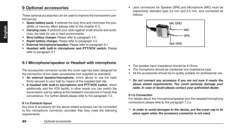
• Jack connectors for Speaker (SPK) and Microphone (MIC) must berespectively standard type 3,5 mm and 2,5 mm. and connected asfollows:
• The speaker input impedance should be 8 Ohms.• The microphone should be condenser low-impedance type.• All the accessories should be hi-quality suitable for professional use.
Do not connect any accessory if you are not sure it meets theabove stated requirements. You could seriously damage yourradio. In case of doubt please contact your authorized dealer.
9.1.b ConnectionFor details about the microphone/speaker and the headset/microphoneconnections please refer to the paragraph 7.2.a
In order to avoid damages to the device, put the cover cap in itsplace again when the accessory connector is not used.
Eng
lish
Spk GND
SPK.
MIC
Mic GND
ISTR106_int 26-09-2003 9:47 Pagina 20
Quick reference 21
10 Quick reference
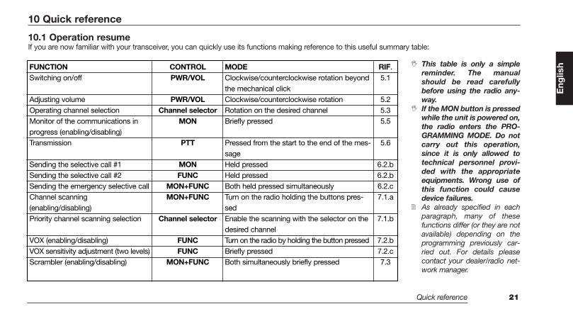
10.1 Operation resumeIf you are now familiar with your transceiver, you can quickly use its functions making reference to this useful summary table:
This table is only a simplereminder. The manualshould be read carefullybefore using the radio any-way.If the MON button is pressedwhile the unit is powered on,the radio enters the PRO-GRAMMING MODE. Do notcarry out this operation,since it is only allowed totechnical personnel provi-ded with the appropriateequipments. Wrong use ofthis function could causedevice failures.As already specified in eachparagraph, many of thesefunctions differ (or they are notavailable) depending on theprogramming previously car-ried out. For details pleasecontact your dealer/radio net-work manager.
Eng
lishFUNCTION
Switching on/off
Adjusting volumeOperating channel selection Monitor of the communications inprogress (enabling/disabling)Transmission
Sending the selective call #1Sending the selective call #2Sending the emergency selective callChannel scanning (enabling/disabling)Priority channel scanning selection
VOX (enabling/disabling)VOX sensitivity adjustment (two levels)Scrambler (enabling/disabling)
CONTROLPWR/VOL
PWR/VOLChannel selector
MON
PTT
MONFUNC
MON+FUNCMON+FUNC
Channel selector
FUNCFUNC
MON+FUNC
MODEClockwise/counterclockwise rotation beyondthe mechanical clickClockwise/counterclockwise rotationRotation on the desired channelBriefly pressed
Pressed from the start to the end of the mes-sageHeld pressedHeld pressedBoth held pressed simultaneouslyTurn on the radio holding the buttons pres-sedEnable the scanning with the selector on thedesired channelTurn on the radio by holding the button pressedBriefly pressedBoth simultaneously briefly pressed
RIF.5.1
5.25.35.5
5.6
6.2.b6.2.b6.2.c 7.1.a
7.1.b
7.2.b7.2.c7.3
ISTR106_int 26-09-2003 9:47 Pagina 21
22 Technical specifications
11 Technical specifications
11.1 Test methods• ETS 300-086• IEC 529 IP54 and MIL STD 810 C/D/E
11.2 Specifications table
Characteristic Units Value/Measurements conditionsGeneralFrequency MHz ALAN HP106: from 148 to 174
ALAN HP406: from 440 to 470Operating Band MHz 26Number of - 16Programmable ChannelsChannel Spacing KHz 12.5 / 20 / 25Frequency Steps KHz 5 / 6.25Rated Power Supply Vdc 7.5Battery Capacity mAh Ni-MH 1.300Duty Cycle hours 5% on TX at the maximum power
5% on RX at 60 % of the maximum rated A.F. power 8 hours90% on RX with closed squelch in power save mode
Antenna Impedance Ohm 50Speaker Impedance Ohm 8Frequency Stability ppm ±2.5Operating Temperature Range °C from –30 to +60
TransmitterOutput Power (±1 dB) W 1 / 5 Spurious Emissions µW from 9 KHz to 1 GHz < 0,25
from 1 to 4 GHz < 1Modulation System - F3E (FM)Modulation KHz ± 2,5 / 5Audio Distortion - 5 % or lessMaximum Deviation KHz ± 2.5 / 5Adjacent Channel dB < -60 / -70Power Attenuation
ReceiverConfiguration - Double Conversion SuperetherodyneSensitivity (at 12 dB SINAD) µV < 0.35Squelch Sensitivity (SINAD) dB 10Selectivity (Adjacent Channel) dB At least -65 / -75Spurious Response Rejection dB > 70Intermodulation dB > 65Hum & Noise Suppression dB < -45 / < -40Audio Output mW 400(1 KHz at 5% T.H.D.)
Mechanical SpecificationsSize (Battery Pack Included) mm 130 x 42 x 60Weight (Battery Pack Included) g 355
yrettab edils kcaB-yrettaBAccessories - 2.5 and 3.5 mm standard monophonicConnector/Programming jacksMoisture & Dust Resistance - According to the IEC529 and IP54
regulations
Eng
lish
ISTR106_int 26-09-2003 9:47 Pagina 22