aja international electron beam evaporator s.o.p… e-beam.pdf · the aja international electron...
TRANSCRIPT
1
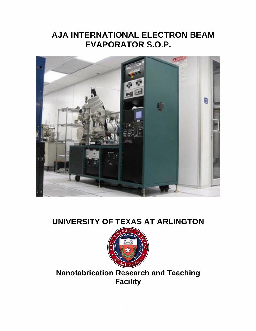
AJA INTERNATIONAL ELECTRON BEAM EVAPORATOR S.O.P.
UNIVERSITY OF TEXAS AT ARLINGTON
Nanofabrication Research and Teaching
Facility
2
TABLE OF CONTENTS 1. Introduction………………………………………………………..3
1.1 Scope of Work………………………………………......3 1.2 Description………………………………………….……3 1.3 Safety……………………………………….……..……..4
2. Requirements……………………………………..….….………..4
2.1 Training…………………………………….……..…..….4 2.2 Restrictions………………………………………….…...4
3. Pre-Checks……………………………….………………………..5
3.1 AJA EBEAM System Checks…………………………..5 3.2 AJA EBEAM Vacuum Pre-Checks……………………..7
4 Operating Procedure ………………………..…..……..……....8
4.1 System AJA Wafer Mounting / Transfer (Load Lock to Main Chamber Transfer)………………..……..…………8
4.2 Ar Plasma Substrate Cleaning Procedure…………….11
4.3 Programming Thickness Monitor/Substrate Holder Rotation/Substrate Heating Procedure………………..13
4.4 Source Material Selection/EBEAM Evaporation Procedure…………………………………………………14
4.5 AJA Wafer Transfer (Main Chamber to Load Lock Transfer……………………………………………………18
4.6 AJA EBEAM Shutdown Procedure…………………….20
3
1 INTRODUCTION
1.1 Scope These procedures apply to the AJA International UHV E-beam evaporator system.
All maintenance should follow the procedures set forth in the manufacturer’s maintenance and operations manuals. This document is for reference only. Personnel should be trained by authorized staff before operating this equipment.
1.2 Description The AJA International Electron Beam Evaporator uses a four position linear slide to
select one of four process crucibles to evaporate/deposit a metal stack or single layer metal on up to 6” diameter wafers, glass slides or small samples. The sample can utilize optional substrate heating and rotation for enhanced film properties. This tool is also equipped with an RF biased wafer holder with Argon gas inlet for optional substrate pre-cleaning to enhance film adhesion. The materials normally supplied in the system by Nanofab are, (Ti, Au, Cr, SiO2, Ni). Due to the fact the system only holds 4 crucibles at a time only 4 of the previously listed materials will be present and the fifth will rotate out as needed.
4
1.3 Safety
1.3.1 This machine is connected to HIGH VOLTAGE. Be very careful and aware of electrical hazards. If you encounter any electrical malfunctions, contact NanoFab staff immediately.
1.3.2 This machine uses RF frequency power. DO NOT operate this machine with any RF cables disconnected, component enclosures/panels open.
1.3.3 This machine can heat substrates to high temperatures (850C°). You must wait until the substrate temperature is < 50C° before transferring your sample to the load lock chamber to remove it from the system.
1.3.4 This machine has only water flow interlocks to prevent over heating the substrate heater, linear source crucibles, RF generator, and quartz crystal. If you encounter any water flow malfunctions or the water flow interlock light comes ON notify NanoFab staff immediately.
1.3.5 This machine has an EMO (Emergency Off) switch/button mounted on the top panel. The EMO switch should be pressed only in an emergency. An emergency would be fire, smoke, electrocution hazards, and an injury to anyone using this particular piece of equipment. If the EMO is pressed notify NanoFab staff immediately.
1.3.6 Use sunglasses when viewing the material heating/evaporation process to prevent eye damage.
2 REQUIREMENTS
2.1 Training You must be a qualified user on AJA Electron Beam Evaporator. The evaporator can be used to deposit films on 1”- 4” diameter wafers, glass slides, and small samples by using the substrate holder clips. Also available is a 6” Aluminum wafer holder which can ONLY be used with substrate heating up to 400C. Extremely small pieces can be processed by using longer holder clips or bonding to larger carrier wafer (bond with drop silver paint, drop of baked photo resist, MUNG II paste or other approved bonding material)
5
2.2 Restrictions
2.2.1 No substrate heating allowed if using bonding material.
2.2.2 The 6” diameter Aluminum substrate holder can be heated up to 400C, heating up to 850C is allowed with the smaller 4” inconel sample carrier plate.
2.2.3 If you are using the substrate heater be careful not to overheat your wafer/samples to prevent any wafer breakage, metal or any other material to flow.
2.2.4 IF you are using the substrate heater the Mounting Plate Rotational controller must be ON to avoid damage to the substrate holder.
2.2.5 If you are using the substrate heater make sure you wait until the substrate temperature is < 50C° before transferring your wafer to the load lock chamber.
2.2.5 When plasma cleaning the wafer the Mounting Plate Rotational controller must be ON.
2.2.6 When plasma cleaning the wafer the heater must be OFF.
3 PRE-CHECKS
3.1 AJA EBEAM System Checks:
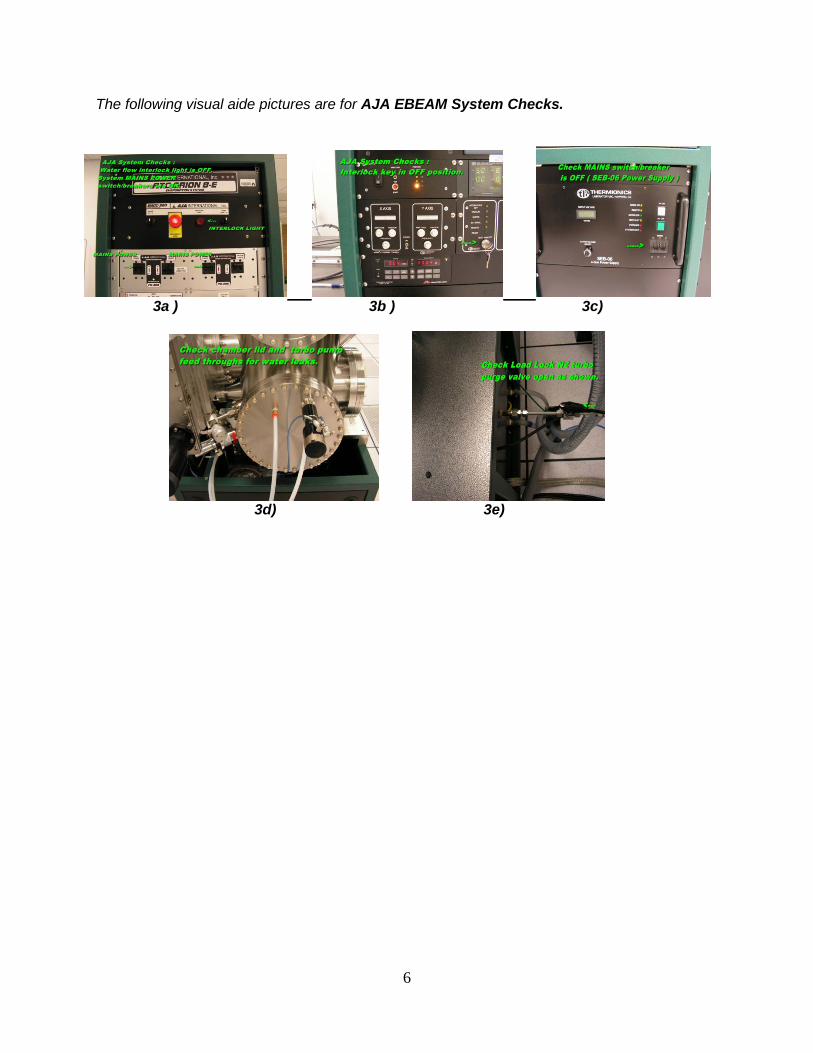
3.1.1 Check to ensure the system water flow interlock light located on the top panel is OFF.
3.1.2 Check to ensure system MAINS POWER switches/breakers (PD-30A , PD-30S) are in the ON position.
3.1.3 Check to ensure the interlock key is in the OFF position.
3.1.4 All the interlock lights should be off.
3.1.5 Check to ensure MAINS switch/breaker for high voltage supply is in the OFF position (SEB-06 e-beam power supply).
3.1.6 Check to ensure the turbo pump and chamber lid water connections and feed throughs have no water leaks.
3.1.7 Check to ensure the Load Lock turbo pump vent valve is in the open position ( the valve pointer in parallel to gas line) . This valve is located at the center rear side of the system.
6
The following visual aide pictures are for AJA EBEAM System Checks.
3a ) 3b ) 3c)
3d) 3e)
7
3.2 AJA EBEAM Vacuum Pre- Checks:
3.2.1 When you first approach the system the MAIN chamber should be in high vacuum and ready to operate. However to ensure equipment performance and minimize equipment down time the following checks MUST be made.
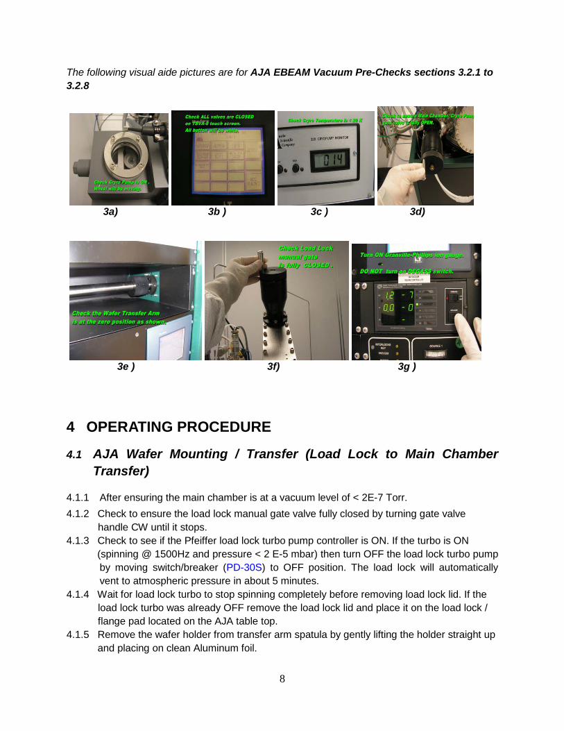
3.2.2 Check to ensure the cryo pump is ON by looking into the cryo pump site glass to check if the wheel is rotating and listen to hear if the cryo pump is ON. IF the cryo pump is OFF call NanoFab staff.
3.2.3 Check to ensure the front panel cryo pump temperature display is < 20K.
3.2.4 Check to ensure the Main Chamber/Cryo Pump manual gate valve is fully open by gently turning manual gate valve handle CW (your closing the gate). If the handle DOES NOT move in the CW direction call NanoFab staff. If the handle moves in the CW direction (this means gate was open) turn handle CW until it stops then immediately open manual gate fully by turning the handle CCW until it stops. The Main Chamber/ Cryo Pump manual gate valve is now fully open.
3.2.5 Check to ensure all pneumatic valves are closed by verifying the TSVA-8 touch screen buttons are all in the OFF position (all buttons will be white). If there are any touch screen buttons that are solid black call NanoFab staff.
3.2.6 Check to ensure wafer transfer arm is at the zero position. (transfer arm moved all the way to the right side).
3.2.7 Check to ensure the Load Lock manual gate valve is fully closed by turning the manual gate valve handle CW until it stops.
3.2.8 If all the vacuum pre-checks are OK then continue.
3.2.8.1 Turn ON Granville-Phillips 340 ION GUAGE. Be careful not to accidentally turn on DEGASS switch!
3.2.8.2 Check to ensure the main chamber is in high vacuum by checking the Granville-Phillips 340 ION GUAGE pressure is < 2E-7 Torr. If the gauge has been off then it may need to warm up for 5 minutes for the reading to drop below this level.
8
The following visual aide pictures are for AJA EBEAM Vacuum Pre-Checks sections 3.2.1 to 3.2.8
3a) 3b ) 3c ) 3d)
3e ) 3f) 3g )
4 OPERATING PROCEDURE
4.1 AJA Wafer Mounting / Transfer (Load Lock to Main Chamber Transfer)
4.1.1 After ensuring the main chamber is at a vacuum level of < 2E-7 Torr. 4.1.2 Check to ensure the load lock manual gate valve fully closed by turning gate valve
handle CW until it stops. 4.1.3 Check to see if the Pfeiffer load lock turbo pump controller is ON. If the turbo is ON (spinning @ 1500Hz and pressure < 2 E-5 mbar) then turn OFF the load lock turbo pump
by moving switch/breaker (PD-30S) to OFF position. The load lock will automatically vent to atmospheric pressure in about 5 minutes.
4.1.4 Wait for load lock turbo to stop spinning completely before removing load lock lid. If the load lock turbo was already OFF remove the load lock lid and place it on the load lock / flange pad located on the AJA table top.
4.1.5 Remove the wafer holder from transfer arm spatula by gently lifting the holder straight up and placing on clean Aluminum foil.
9
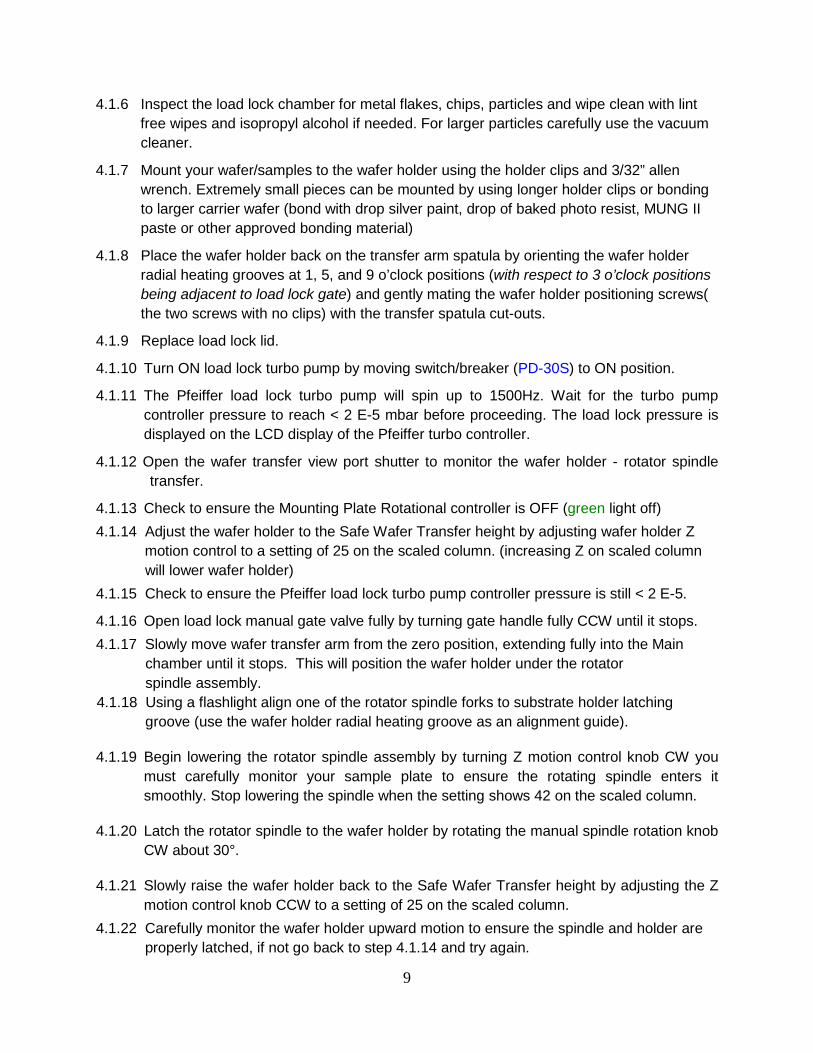
4.1.6 Inspect the load lock chamber for metal flakes, chips, particles and wipe clean with lint free wipes and isopropyl alcohol if needed. For larger particles carefully use the vacuum cleaner.
4.1.7 Mount your wafer/samples to the wafer holder using the holder clips and 3/32” allen wrench. Extremely small pieces can be mounted by using longer holder clips or bonding to larger carrier wafer (bond with drop silver paint, drop of baked photo resist, MUNG II paste or other approved bonding material)
4.1.8 Place the wafer holder back on the transfer arm spatula by orienting the wafer holder radial heating grooves at 1, 5, and 9 o’clock positions (with respect to 3 o’clock positions being adjacent to load lock gate) and gently mating the wafer holder positioning screws( the two screws with no clips) with the transfer spatula cut-outs.
4.1.9 Replace load lock lid.
4.1.10 Turn ON load lock turbo pump by moving switch/breaker (PD-30S) to ON position.
4.1.11 The Pfeiffer load lock turbo pump will spin up to 1500Hz. Wait for the turbo pump controller pressure to reach < 2 E-5 mbar before proceeding. The load lock pressure is displayed on the LCD display of the Pfeiffer turbo controller.
4.1.12 Open the wafer transfer view port shutter to monitor the wafer holder - rotator spindle transfer.
4.1.13 Check to ensure the Mounting Plate Rotational controller is OFF (green light off) 4.1.14 Adjust the wafer holder to the Safe Wafer Transfer height by adjusting wafer holder Z motion control to a setting of 25 on the scaled column. (increasing Z on scaled column will lower wafer holder) 4.1.15 Check to ensure the Pfeiffer load lock turbo pump controller pressure is still < 2 E-5.
4.1.16 Open load lock manual gate valve fully by turning gate handle fully CCW until it stops. 4.1.17 Slowly move wafer transfer arm from the zero position, extending fully into the Main
chamber until it stops. This will position the wafer holder under the rotator spindle assembly. 4.1.18 Using a flashlight align one of the rotator spindle forks to substrate holder latching groove (use the wafer holder radial heating groove as an alignment guide).
4.1.19 Begin lowering the rotator spindle assembly by turning Z motion control knob CW you must carefully monitor your sample plate to ensure the rotating spindle enters it smoothly. Stop lowering the spindle when the setting shows 42 on the scaled column.
4.1.20 Latch the rotator spindle to the wafer holder by rotating the manual spindle rotation knob CW about 30°.
4.1.21 Slowly raise the wafer holder back to the Safe Wafer Transfer height by adjusting the Z motion control knob CCW to a setting of 25 on the scaled column.
4.1.22 Carefully monitor the wafer holder upward motion to ensure the spindle and holder are properly latched, if not go back to step 4.1.14 and try again.
10
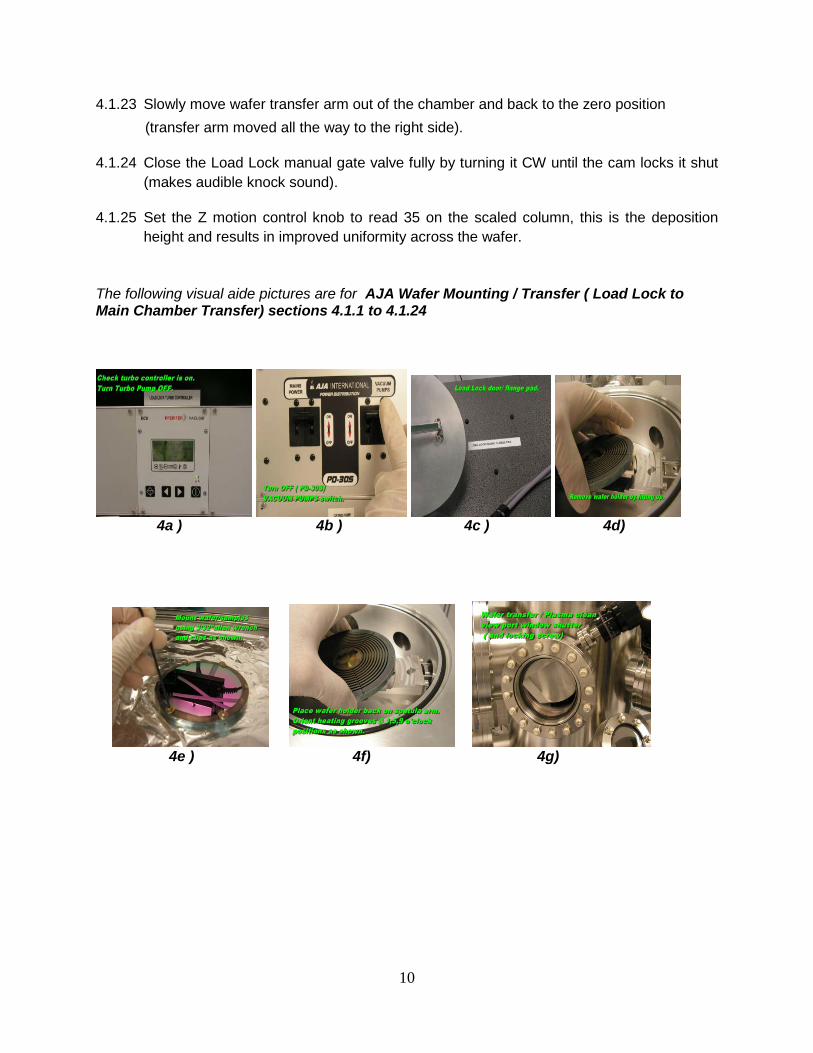
4.1.23 Slowly move wafer transfer arm out of the chamber and back to the zero position (transfer arm moved all the way to the right side).
4.1.24 Close the Load Lock manual gate valve fully by turning it CW until the cam locks it shut (makes audible knock sound).
4.1.25 Set the Z motion control knob to read 35 on the scaled column, this is the deposition height and results in improved uniformity across the wafer.
The following visual aide pictures are for AJA Wafer Mounting / Transfer ( Load Lock to Main Chamber Transfer) sections 4.1.1 to 4.1.24
4a ) 4b ) 4c ) 4d)
4e ) 4f) 4g)

11
4h ) 4i ) 4j )
4.2 Ar Plasma Substrate Cleaning Procedure (Optional)
4.2.1 The Ar gas bottle will normally be open. Check to ensure the gas delivery pressure is 5 psig. If the delivery pressure is not 5 psig call NanoFab staff to adjust the delivery pressure. 4.2.2 Turn OFF Granville-Phillips 340 ION GUAGE. 4.2.3 Open the view port shutter to monitor plasma and rotation operations. 4.2.4 Check to ensure the substrate heater is OFF. 4.2.5 When plasma cleaning substrate rotation must be ON. 4.2.6 Start substrate rotation by setting the Mounting Plate Rotational controller to 50. 4.2.7 Check to ensure Ar gas needle valve is fully closed by gently turning needle valve CW
until it stops 4.2.8 Open Ar gas valve by pressing SUBSTRATE GAS button on the TSVA-8 touch screen (SUBSTRATE GAS button will turn black). Be very careful when pressing touch screen buttons because they are small and the wrong button can easily be pressed. 4.2.9 To monitor the chamber pressure during plasma cleaning use the Granville-Phillips 340 vacuum gauge (GUAGE A). 4.2.10 Adjust Ar needle valve ½ turn CCW until chamber pressure is 2 mtorr.
4.2.11 Turn Main Chamber/ Cryo Pump manual gate valve handle CW until chamber pressure is 35 mtorr ( GAUGE A will display 3.5 -2 )
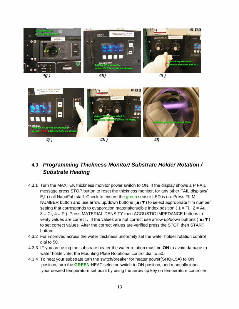
4.2.12 Select PANEL MODE on SEREN RF generator. 4.2.13 Check to ensure the RF matching network’s SOURCE POSITION is set to 1.
4.2.14 Set the forward power to 25 Watts by using the arrow up button (▲) on the SEREN generator. Set the initial matching network tune set points to TUNE = 56,and LOAD =54 This is the plasma striking set points. 4.2.15 Turn on RF power by pressing RF ON button ( red led will go on) 4.2.16 Adjust the TUNE then LOAD on manual matching network to get minimum reflected
power ( 0 Watts ) on the SEREN generator’s REF power display. 4.2.17 The plasma should strike and DCV will be displayed on SEREN generator. 4.2.18 Turn Main Chamber/ Cryo Pump manual gate valve handle CCW until chamber
pressure is 5 mtorr (approximately 1 turn of handle CCW). This is the sputter clean plasma pressure. 4.2.19 Adjust TUNE then LOAD again on the manual matching network to get minimum
reflected power ( 0 Watts ) on the SEREN generator’s REF power display.
12
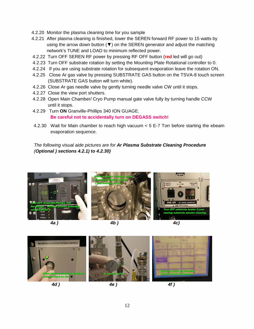
4.2.20 Monitor the plasma cleaning time for you sample 4.2.21 After plasma cleaning is finished, lower the SEREN forward RF power to 15 watts by using the arrow down button (▼) on the SEREN generator and adjust the matching network’s TUNE and LOAD to minimum reflected power.
4.2.22 Turn OFF SEREN RF power by pressing RF OFF button (red led will go out) 4.2.23 Turn OFF substrate rotation by setting the Mounting Plate Rotational controller to 0.
4.2.24 If you are using substrate rotation for subsequent evaporation leave the rotation ON. 4.2.25 Close Ar gas valve by pressing SUBSTRATE GAS button on the TSVA-8 touch screen
(SUBSTRATE GAS button will turn white). 4.2.26 Close Ar gas needle valve by gently turning needle valve CW until it stops. 4.2.27 Close the view port shutters. 4.2.28 Open Main Chamber/ Cryo Pump manual gate valve fully by turning handle CCW until it stops. 4.2.29 Turn ON Granville-Phillips 340 ION GUAGE. Be careful not to accidentally turn on DEGASS switch!
4.2.30 Wait for Main chamber to reach high vacuum < 5 E-7 Torr before starting the ebeam evaporation sequence.
The following visual aide pictures are for Ar Plasma Substrate Cleaning Procedure (Optional ) sections 4.2.1) to 4.2.30)
4a ) 4b ) 4c)
4d ) 4e ) 4f )
13
4g ) 4h) 4i )
4j ) 4k ) 4l)
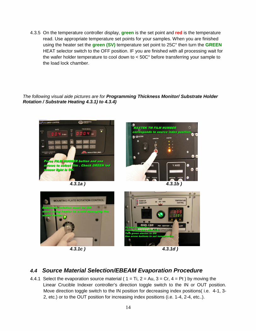
4.3 Programming Thickness Monitor/ Substrate Holder Rotation / Substrate Heating
4.3.1 Turn the MAXTEK thickness monitor power switch to ON. If the display shows a P FAIL message press STOP button to reset the thickness monitor, for any other FAIL displays( E,I ) call NanoFab staff. Check to ensure the green sensor LED is on. Press FILM NUMBER button and use arrow up/down buttons (▲/▼) to select appropriate film number setting that corresponds to evaporation material/crucible index position ( 1 = Ti, 2 = Au, 3 = Cr, 4 = Pt) .Press MATERIAL DENSITY then ACOUSTIC IMPEDANCE buttons to verify values are correct . If the values are not correct use arrow up/down buttons ( ▲/▼) to set correct values. After the correct values are verified press the STOP then START button. 4.3.2 For improved across the wafer thickness uniformity set the wafer holder rotation control dial to 50.
4.3.3 IF you are using the substrate heater the wafer rotation must be ON to avoid damage to wafer holder. Set the Mounting Plate Rotational control dial to 50. 4.3.4 To heat your substrate turn the switch/breaker for heater power(SHQ-15A) to ON
position, turn the GREEN HEAT selector switch to ON position, and manually input your desired temperature set point by using the arrow up key on temperature controller.
14
4.3.5 On the temperature controller display, green is the set point and red is the temperature read. Use appropriate temperature set points for your samples. When you are finished using the heater set the green (SV) temperature set point to 25C° then turn the GREEN HEAT selector switch to the OFF position. IF you are finished with all processing wait for the wafer holder temperature to cool down to < 50C° before transferring your sample to the load lock chamber.
The following visual aide pictures are for Programming Thickness Monitor/ Substrate Holder Rotation / Substrate Heating 4.3.1) to 4.3.4)
4.3.1a ) 4.3.1b )
4.3.1c ) 4.3.1d )
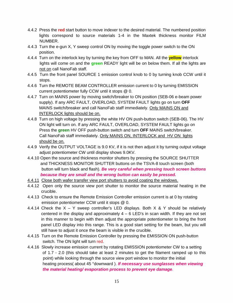
4.4 Source Material Selection/EBEAM Evaporation Procedure 4.4.1 Select the evaporation source material ( 1 = Ti, 2 = Au, 3 = Cr, 4 = Pt ) by moving the
Linear Crucible Indexer controller’s direction toggle switch to the IN or OUT position. Move direction toggle switch to the IN position for decreasing index positions( i.e. 4-1, 3-2, etc.) or to the OUT position for increasing index positions (i.e. 1-4, 2-4, etc..).
15
4.4.2 Press the red start button to move indexer to the desired material. The numbered position lights correspond to source materials 1-4 in the Maxtek thickness monitor FILM
NUMBER. 4.4.3 Turn the e-gun X, Y sweep control ON by moving the toggle power switch to the ON position.
4.4.4 Turn on the interlock key by turning the key from OFF to MAN. All the yellow interlock lights will come on and the green READY light will be on below them. If all the lights are
not on4.4.5 Turn the front panel SOURCE 1 emission control knob to 0 by turning knob CCW until it
stops.
call NanoFab staff.
4.4.6 Turn the REMOTE BEAM CONTROLLER emission current to 0 by turning EMISSION current potentiometer fully CCW until it stops @ 0.
4.4.7 Turn on MAINS power by moving switch/breaker to ON position (SEB-06 e-beam power supply). If any ARC FAULT, OVERLOAD, SYSTEM FAULT lights go on turn OFF MAINS switch/breaker and call NanoFab staff immediately.
Only MAINS ON and
4.4.8 Turn on high voltage by pressing the white HV ON push-button switch (SEB-06). The HV INTERLOCK lights should be on.
ON light will turn on. If any ARC FAULT, OVERLOAD, SYSTEM FAULT lights go on Press the green HV OFF push-button switch and turn OFF MAINS switch/breaker. Call NanoFab staff immediately.
Only MAINS ON, INTERLOCK and HV ON lights
4.4.9 Verify the OUTPUT VOLTAGE is 9.0 KV, if it is not then adjust it by turning output voltage adjust potentiometer CW until display shows 9.0KV.
should be on.
4.4.10 Open the source and thickness monitor shutters by pressing the SOURCE SHUTTER and THICKNESS MONITOR SHUTTER buttons on the TSVA-8 touch screen (both button will turn black and flash). Be very careful when pressing touch screen buttons because they are small and the wrong button can easily be pressed.
4.4.11 4.4.12 Open only the source view port shutter to monitor the source material heating in the
crucible.
Close both wafer transfer view port shutters to avoid coating the windows.
4.4.13 Check to ensure the Remote Emission Controller emission current is at 0 by rotating emission potentiometer CCW until it stops @ 0.
4.4.14 Check the X – Y sweep controller’s LED displays. Both X & Y should be relatively centered in the display and approximately 4 – 6 LED’s in scan width. If they are not set in this manner to begin with then adjust the appropriate potentiometer to bring the front panel LED display into this range. This is a good start setting for the beam, but you will still have to adjust it once the beam is visible in the crucible.
4.4.15 Turn on the Remote Emission Controller by pressing the EMISSION ON push-button switch. The ON light will turn red. 4.4.16 Slowly increase emission current by rotating EMISSION potentiometer CW to a setting of 1.7 - 2.0 (this should take at least 2 minutes to get the filament ramped up to this
point) while looking through the source view port window to monitor the initial heating process( about 45 °downward ). If necessary use sunglasses when viewing the material heating/ evaporation process to prevent eye damage.
16
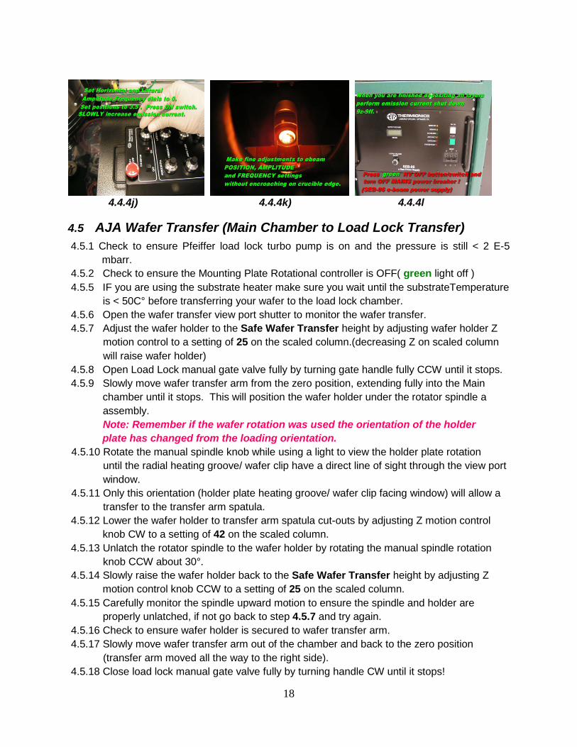
4.4.17 You should be able to see the blue ebeam spot or the material glowing hot near the center of the crucible. Make fine centering adjustments to the Horizontal and Lateral Position potentiometers. 4.4.19 Increase/decrease the Horizontal Amplitude potentiometer CW to generate an optimal
e-beam sweep without encroaching on the crucible edge. 4.4.20 Increase/decrease the Lateral Amplitude potentiometer CW to generate an optimal e-
beam sweep without encroaching on the crucible edge. A Lateral Amplitude setting 1-2 should be sufficient.
4.4.21 Increase the Horizontal and Lateral Frequency potentiometers CW to achieve an optimum sweep frequency/speed. 4.4.22 Very slowly increase emission current by rotating EMISSION potentiometer CW.When the material starts to melt or you have a deposition rate on MAXTEK TM monitor close the source view port shutter and tightened the shutter locking knob to avoid coating the window.Start monitoring the MAXTEK TM.
4.4.23 When you have an evaporation rate of 2-3A/sec press the STOP then START buttons on the MAXTEK thickness monitor.
4.4.24 Open the substrate shutter by pressing the SUBSTRATE SHUTTER button on the TSVA-8 touch screen (button will turn black and flash). 4.4.25 When you have deposited the desired thickness close the substrate shutter by pressing the SUBSTRATE SHUTTER button on the TSVA-8 touch screen (button will turn white).
4.4.26 Close the source and thickness monitor shutters by pressing the SOURCE SHUTTER and THICKNESS MONITOR SHUTTER buttons on the TSVA-8 touch screen (both button’s will turn white).
4.4.27 Begin the emission current shut down by SLOWLY decreasing emission current by rotating EMISSION potentiometer CCW until it stops @ 0. This ramp down should take
a minimum of 2 minutes. 4.4.28 Turn off the Remote Emission Controller by pressing the EMISSION OFF push-button switch. The OFF light will turn green. 4.4.33 Turn off high voltage by pressing the green HV OFF push-button switch (SEB-06). Turn
off the MAINS power by moving switch/breaker to the OFF position (SEB-06 e-beam power supply).
4.4.34 If you are going to evaporate another layer WITHOUT Ar PLASMA CLEANING go back to section 4.3 4.4.35 If you are going to evaporate another layer WITH Ar PLASMA CLEANING go back to section 4.2 4.4.36 If you are finished depositing materials continue to the next step. 4.4.37 Turn off the interlock key by turning the key from MAN to OFF. 4.4.38 All the interlock lights will go off. 4.4.39 Turn the e-gun X, Y sweep control OFF by moving the toggle power switch to the OFF
position.
17
4.4.40 If the substrate heater was used set the green (SV) temperature to 25C° then turn turn the GREEN HEAT selector switch to the OFF position and wait for the substrate holder temperature to cool down to < 50 C° before transferring your wafer to the load lock chamber.
4.4.41 Turn OFF substrate rotation by turning Mounting Plate Rotational controller dial to 0. (The green indicator light will turn off).
The following visual aide pictures are for Source Material Selection/ / EBEAM Evaporation Procedure sections 4.4.4.1) to 4.4.41)
4.4.4a ) 4.4.4b ) 4.4.4c )
4.4.4d ) 4.4.4e ) 4.4.4f )
4.4.4g ) 4.4.4h) 4.4.4i )
18
4.4.4j) 4.4.4k) 4.4.4l
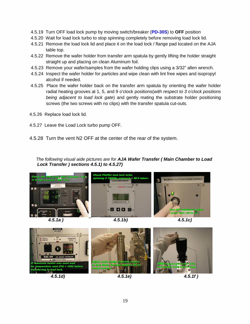
4.5 AJA Wafer Transfer (Main Chamber to Load Lock Transfer) 4.5.1 Check to ensure Pfeiffer load lock turbo pump is on and the pressure is still < 2 E-5
mbarr. 4.5.2 Check to ensure the Mounting Plate Rotational controller is OFF( green light off ) 4.5.5 IF you are using the substrate heater make sure you wait until the substrateTemperature is < 50C° before transferring your wafer to the load lock chamber. 4.5.6 Open the wafer transfer view port shutter to monitor the wafer transfer. 4.5.7 Adjust the wafer holder to the Safe Wafer Transfer height by adjusting wafer holder Z
motion control to a setting of 25 on the scaled column.(decreasing Z on scaled column will raise wafer holder)
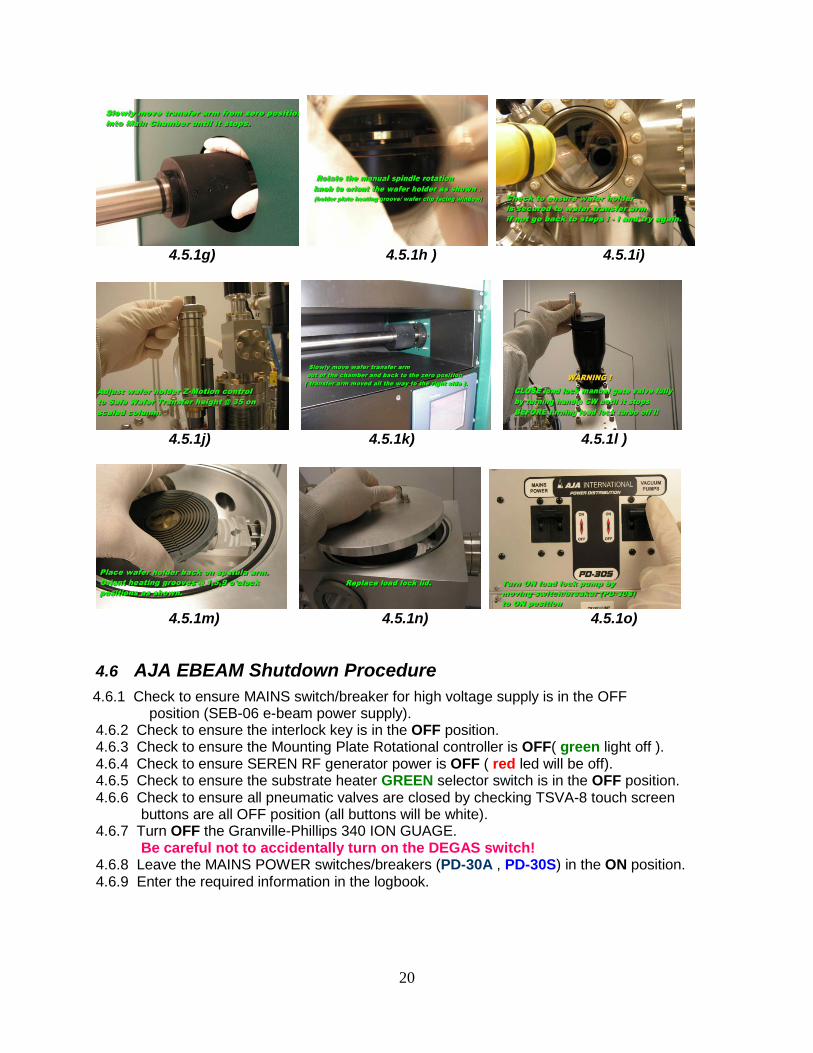
4.5.8 Open Load Lock manual gate valve fully by turning gate handle fully CCW until it stops. 4.5.9 Slowly move wafer transfer arm from the zero position, extending fully into the Main chamber until it stops. This will position the wafer holder under the rotator spindle a assembly. Note: Remember if the wafer rotation was used the orientation of the holder
plate has changed from the loading orientation. 4.5.10 Rotate the manual spindle knob while using a light to view the holder plate rotation until the radial heating groove/ wafer clip have a direct line of sight through the view port window. 4.5.11 Only this orientation (holder plate heating groove/ wafer clip facing window) will allow a transfer to the transfer arm spatula.
4.5.12 Lower the wafer holder to transfer arm spatula cut-outs by adjusting Z motion control knob CW to a setting of 42 on the scaled column. 4.5.13 Unlatch the rotator spindle to the wafer holder by rotating the manual spindle rotation
knob CCW about 30°. 4.5.14 Slowly raise the wafer holder back to the Safe Wafer Transfer height by adjusting Z motion control knob CCW to a setting of 25 on the scaled column. 4.5.15 Carefully monitor the spindle upward motion to ensure the spindle and holder are properly unlatched, if not go back to step 4.5.7 and try again. 4.5.16 Check to ensure wafer holder is secured to wafer transfer arm. 4.5.17 Slowly move wafer transfer arm out of the chamber and back to the zero position
(transfer arm moved all the way to the right side). 4.5.18 Close load lock manual gate valve fully by turning handle CW until it stops!
19
4.5.19 Turn OFF load lock pump by moving switch/breaker (PD-30S) to OFF position 4.5.20 Wait for load lock turbo to stop spinning completely before removing load lock lid.
4.5.21 Remove the load lock lid and place it on the load lock / flange pad located on the AJA table top.
4.5.22 Remove the wafer holder from transfer arm spatula by gently lifting the holder straight straight up and placing on clean Aluminum foil. 4.5.23 Remove your wafer/samples from the wafer holding clips using a 3/32” allen wrench. 4.5.24 Inspect the wafer holder for particles and wipe clean with lint free wipes and isopropyl alcohol if needed.
4.5.25 Place the wafer holder back on the transfer arm spatula by orienting the wafer holder radial heating grooves at 1, 5, and 9 o’clock positions(with respect to 3 o’clock positions being adjacent to load lock gate) and gently mating the substrate holder positioning screws (the two screws with no clips) with the transfer spatula cut-outs.
4.5.26 Replace load lock lid.
4.5.27 Leave the Load Lock turbo pump OFF. 4.5.28 Turn the vent N2 OFF at the center of the rear of the system.
The following visual aide pictures are for AJA Wafer Transfer ( Main Chamber to Load Lock Transfer ) sections 4.5.1) to 4.5.27)
4.5.1a ) 4.5.1b) 4.5.1c)
4.5.1d) 4.5.1e) 4.5.1f )
20
4.5.1g) 4.5.1h ) 4.5.1i)
4.5.1j) 4.5.1k) 4.5.1l )
4.5.1m) 4.5.1n) 4.5.1o)
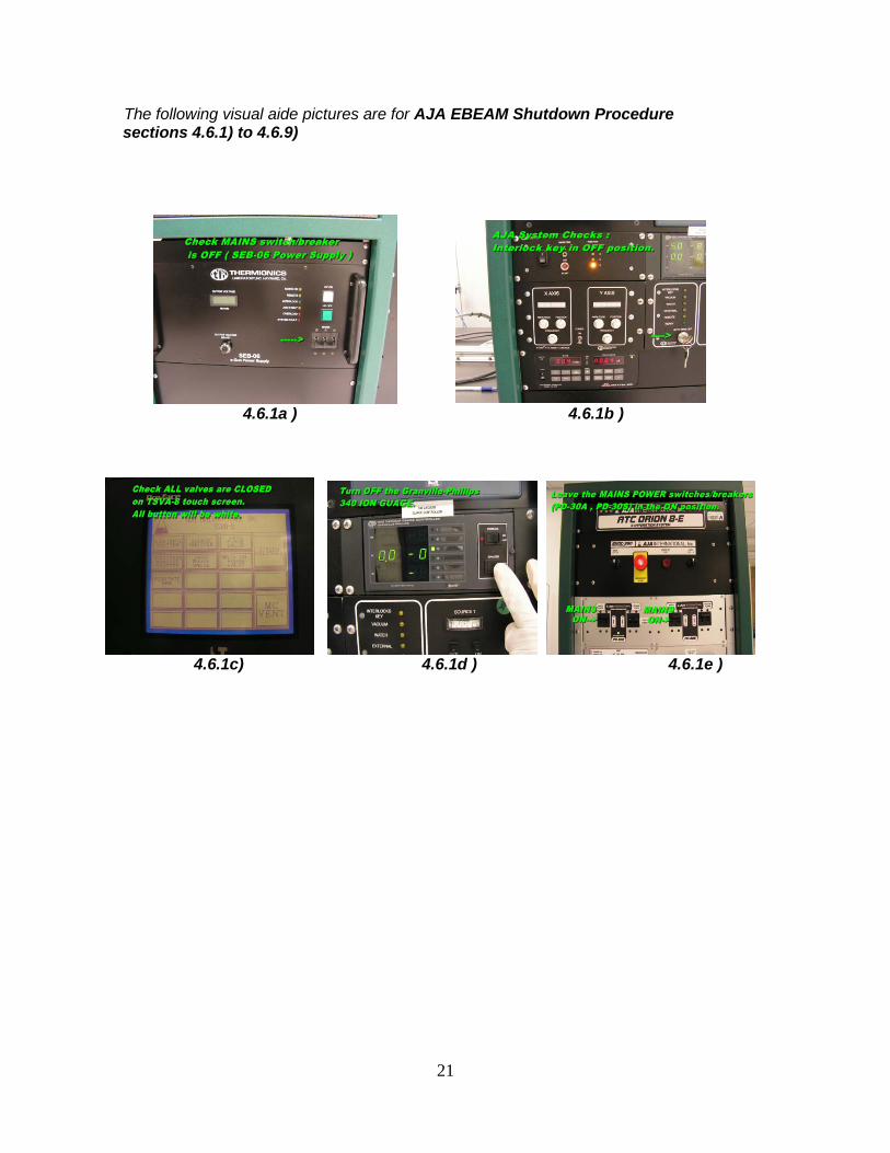
4.6 AJA EBEAM Shutdown Procedure 4.6.1 Check to ensure MAINS switch/breaker for high voltage supply is in the OFF
position (SEB-06 e-beam power supply). 4.6.2 Check to ensure the interlock key is in the OFF position. 4.6.3 Check to ensure the Mounting Plate Rotational controller is OFF( green light off ). 4.6.4 Check to ensure SEREN RF generator power is OFF ( red led will be off). 4.6.5 Check to ensure the substrate heater GREEN selector switch is in the OFF position. 4.6.6 Check to ensure all pneumatic valves are closed by checking TSVA-8 touch screen
buttons are all OFF position (all buttons will be white). 4.6.7 Turn OFF the Granville-Phillips 340 ION GUAGE.
Be careful not to accidentally turn on the DEGAS switch! 4.6.8 Leave the MAINS POWER switches/breakers (PD-30A , PD-30S) in the ON position. 4.6.9 Enter the required information in the logbook.
21
The following visual aide pictures are for AJA EBEAM Shutdown Procedure sections 4.6.1) to 4.6.9)
4.6.1a ) 4.6.1b )
4.6.1c) 4.6.1d ) 4.6.1e )