airline pneumatic accessories
TRANSCRIPT

AirlineAccessories
Catalog WACC-01/USA
Pneumatic

Watts FluidAirPneumatic Division
Pneumatic
Catalog WACC-01/USA
! WARNINGFAILURE OR IMPROPER SELECTION OR IMPROPER USE OF THE PRODUCTS AND/OR SYSTEMS DESCRIBEDHEREIN OR RELATED ITEMS CAN CAUSE DEATH, PERSONAL INJURY AND PROPERTY DAMAGE.
This document and other information from Parker Hannifin Corporation, its subsidiaries and authorized distributors provideproduct and/or system options for further investigation by users having technical expertise. It is important that you analyzeall aspects of your application including consequences of any failure, and review the information concerning the product orsystem in the current product catalog. Due to the variety of operating conditions and applications for these products orsystems, the user, through its own analysis and testing, is solely responsible for making the final selection of the productsand systems and assuring that all performance, safety and warning requirements of the application are met.The products described herein, including without limitation, product features, specifications, designs, availability and pricing,are subject to change by Parker Hannifin Corporation and its subsidiaries at any time without notice.
Offer of SaleThe items described in this document are hereby offered for sale by Parker Hannifin Corporation, its subsidiaries or itsauthorized distributors. This offer and its acceptance are governed by the provisions stated on the separate page of thisdocument entitled “Offer of Sale”.
© Copyright 2001, 2003, Parker Hannifin Corporation. All Rights Reserved

Watts FluidAirPneumatic Division
Pneumatic
Catalog WACC-01/USA
Safety Blow Guns 1-6
Ball Valves, Plug Valves 1-6
Lockout Valves 1-6
Flow Controls & Accessories 1-20
Fittings & Hose 1-12
Fittings & Tubing 1-70
Airline Accessories 1-4
Quick Couplings & Adapters 1-16
Offer of Sale
Airline AccessoriesProduct Selection ChartIndex
CDEFG
AB
H

Watts FluidAirPneumatic Division
Pneumatic
A
Safety Blow Guns
Section A
Pneumatic
Brass Nozzle & Aspirator Blow Guns ......................... 2Vortec FLO-GAIN & Self Regulating Blow Guns ........ 3Button Type Brass & Pistol Grip Blow Guns ............... 4Blow Gun Accessories ............................................... 5Replacement Parts ..................................................... 6

2 Watts FluidAirPneumatic Division
Pneumatic
Catalog WACC-01/USA
O.S.H.A. Certification — All safety blow guns conform to the requirements of Compressed Air Standards ascurrently described in the U.S. Bureau of Labor Standards, paragraph 1910.242, when pressurized at the inletto a maximum of 100 PSIG. Conform to current O.S.H.A. Directive No. 100-1.
Brass Nozzle Blow GunsContoured lever or button control both provide a natural,comfortable grip even when used with gloves. Fingerguard and hang-up hook for finger protection and quicksafe storage. Die cast zinc body, painted finish.
Aspirator Blow GunsDual air shield provides wide fan of air to reduce chipblow back. Secondary shielding is provided by four radialholes for close in work. Aspirator nozzle gives heavyduty chip blowing performance without exceeding legallimits. Pressure relieves to safe limits if nozzle is blocked.Finger guard and hang-up hook offer desirable fingerprotection and quick secure storage. Die cast zinc body,painted finish.
*Based on 100 PSIG inlet pressure.
*Based on 100 PSIG inlet pressure.
Part Inlet SCFMNumber Port Rating*
00475 0010 1/4" 20
Lever Operated
Part Inlet SCFMNumber Port Rating*
00470 0010 1/4" 20
Button Operated
Part Inlet SCFMNumber Port Rating*
00475 0474 1/4" 74.5
Lever Operated
Part Inlet SCFMNumber Port Rating*
00470 0474 1/4" 74.5
Button Operated
Safety Blow GunsBrass Nozzle & Aspirator Blow GunsSafety Blow Guns

3 Watts FluidAirPneumatic Division
Pneumatic
Catalog WACC-01/USA
AVortec FLO-GAIN Blow GunsA quiet Vortec FLO-GAIN nozzle is combined with a highperformance blow gun. Compressed air attains sonicvelocity through an adjustable slot and attaches to theexterior surface of the cone shaped nozzle. Settings areshown on a micrometer dial. Sound level of 80 dBA with80 PSIG inlet. Finger guard and hang-up hook offersdesirable finger protection and quick secure storage.Die cast zinc body, painted finish.
*Based on 100 PSIG inlet pressure.
Part Inlet SCFMNumber Port Rating*
00470 0900 1/4" 70+
Button Operated
Part Inlet SCFMNumber Port Rating*
00475 0900 1/4" 70+
Lever Operated
Self-Regulating Blow GunDesigned with integral self-regulating pressure reducingvalve for automatic shut-off when nozzle is blocked.Prevents air pressure buildup over 30 PSIG incompliance with U.S. Dept. of Labor standards.
Air shield aids in protecting the operator against blowback of flying chips of dirt. Designed to operate at lessthan 90 dBA to comply with government regulations.Die cast zinc body, painted finish.
May be used with nozzle extensions on Page 5.
Part Inlet SCFMNumber Port Rating*
00475 2900 1/4" 10
Ordering Information
Inlet Blocked SoundPressure Pressure Level
70 PSIG 17.0 PSIG 79 dBA100 PSIG 21.0 PSIG 83 dBA175 PSIG 28.0 PSIG 87 dBA
Performance Data
*Based on 100 PSIG inlet pressure.
Safety Blow GunsVortec FLO-GAIN & Self Regulating GunsSafety Blow Guns

4 Watts FluidAirPneumatic Division
Pneumatic
Catalog WACC-01/USA
Button Type Brass Blow GunThese general purpose blow guns are ideal for almostany cleaning purpose. Their drop forged brass bodiesprovide strength and long life. Corrosion resistant parts.May be used for spraying many light liquids. Availablewith standard brass nozzle.
Part Inlet SCFMNumber Port Rating*
07184 1000 1/4" 20
*Based on 100 PSIG inlet pressure.
Pistol Grip Blow GunPistol grip is easy to aim for quick and efficientcleaning. Ideal for all shop housekeeping purposes.Lightweight and easy to handle. Easy trigger actionfeatures instant spring adjustment for controlled air.Get the amount of air where you want it with norestrictions, no cut-offs! Makes for a convenientconnection for overhead or underbench floorair use.
Part Inlet SCFMNumber Port Rating*
BG441-NBL 1/4" 11.0
*Based on 100 PSIG inlet pressure.
Safety Blow GunsButton Type Brass & Pistol Grip Blow GunsSafety Blow Guns

5 Watts FluidAirPneumatic Division
Pneumatic
Catalog WACC-01/USA
ABrass NozzleModel No. 00470 7020General purpose nozzles are supplied as standard on00470 0010, 00475 0010 and 07184 1000 blow guns.Conform to the requirements of the Williams SteigerOccupational Safety and Health Act of 1970, paragraph1910.242 when fitted with blow guns pressurized at theinlet to a maximum of 100 PSIG. Conform to O.S.H.A.Directive 100-1.
Aspirator NozzleModel No. 00474 1000Protect against personal injury by relieving pressure if thenozzle end is blocked. Develop exceptionally high flowrates which insure effective cleaning. Conform to therequirements of the Williams Steiger Occupational Safetyand Health Act of 1970, paragraphs 1910.95 and1910.242 when fitted with blow guns pressurized at theinlet to a maximum of 100 PSIG. Conform to O.S.H.A.Directive 100-1.
FLO-GAIN NozzleModel No. W1110 0900This FLO-GAIN nozzle is the most widely used of thetransvector products for industrial blow off. Compressedair attains sonic velocity through an adjustable slot andattaches to the cone shaped exterior surface of the nozzle.Induction and entrainment take place outside the nozzle.Factory slot setting is .008 inch, but is adjustable fromclosed to .012 inch. A micrometer dial allows adjustmentwithout the use of shims or gauges.
Must be used with filtered air.
U.S. Patent No. 3,647,142
Safety Blow GunsConform to O.S.H.A.Blow Gun Accessories
6 Watts FluidAirPneumatic Division
Pneumatic
Catalog WACC-01/USA
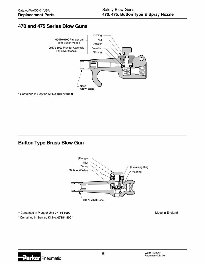
470 and 475 Series Blow Guns
† Contained in Plunger Unit 07184 8000
* Contained in Service Kit No. 07184 8001
Made in England
Button Type Brass Blow Gun
†Retaining Ring
†Plunger
†Nut†*O-ring
†*Rubber Washer
00470 7020 Nose
O-Ring
Nut
Deflator
*Washer*Spring
Nose00470 7020
00470 0100 Plunger Unit(For Button Models)
00470 8003 Plunger Assembly(For Lever Models)
* Contained in Service Kit No. 00470 0090
†Spring
Safety Blow Guns470, 475, Button Type & Spray NozzleReplacement Parts

Watts FluidAirPneumatic Division
Pneumatic
B
Ball Valves1/4" to 2", 2-Way1/4" to 1", 2-Way Vented
Plug Valves1/8" to 1/4" Pipe Size
Section B
Ball Valve Basic Features ..........................................2Ball Valve Part Numbers & Dimensions ................. 3-4
Plug Valve Basic Features .........................................5Plug Valve Part Numbers & Dimensions ....................6
Pneumatic
2 Watts FluidAirPneumatic Division
Pneumatic
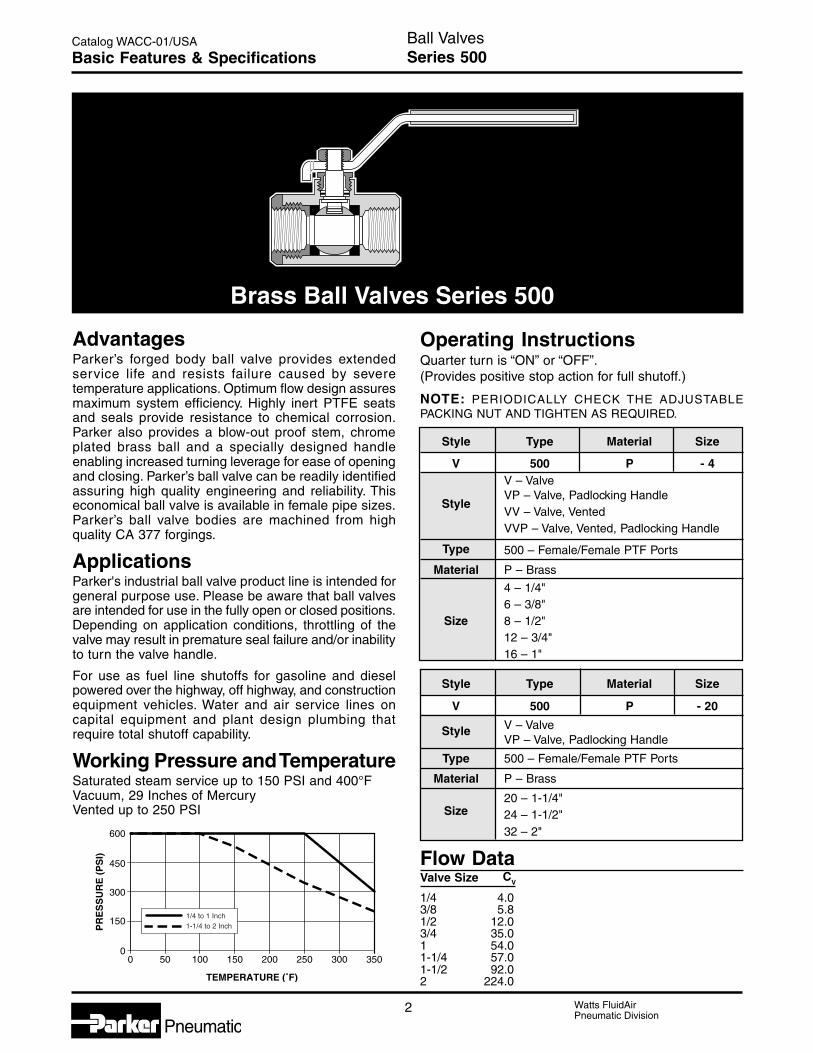
Catalog WACC-01/USA Ball ValvesSeries 500Basic Features & Specifications
AdvantagesParker’s forged body ball valve provides extendedservice life and resists failure caused by severetemperature applications. Optimum flow design assuresmaximum system efficiency. Highly inert PTFE seatsand seals provide resistance to chemical corrosion.Parker also provides a blow-out proof stem, chromeplated brass ball and a specially designed handleenabling increased turning leverage for ease of openingand closing. Parker’s ball valve can be readily identifiedassuring high quality engineering and reliability. Thiseconomical ball valve is available in female pipe sizes.Parker’s ball valve bodies are machined from highquality CA 377 forgings.
ApplicationsParker's industrial ball valve product line is intended forgeneral purpose use. Please be aware that ball valvesare intended for use in the fully open or closed positions.Depending on application conditions, throttling of thevalve may result in premature seal failure and/or inabilityto turn the valve handle.
For use as fuel line shutoffs for gasoline and dieselpowered over the highway, off highway, and constructionequipment vehicles. Water and air service lines oncapital equipment and plant design plumbing thatrequire total shutoff capability.
Working Pressure and TemperatureSaturated steam service up to 150 PSI and 400°FVacuum, 29 Inches of MercuryVented up to 250 PSI
Operating InstructionsQuarter turn is “ON” or “OFF”.(Provides positive stop action for full shutoff.)
NOTE: PERIODICALLY CHECK THE ADJUSTABLEPACKING NUT AND TIGHTEN AS REQUIRED.
Style Type Material Size
V 500 P - 4V – Valve
StyleVP – Valve, Padlocking HandleVV – Valve, VentedVVP – Valve, Vented, Padlocking Handle
Type 500 – Female/Female PTF Ports
Material P – Brass
4 – 1/4"6 – 3/8"
Size 8 – 1/2"12 – 3/4"16 – 1"
Style Type Material Size
V 500 P - 20
V – ValveStyleVP – Valve, Padlocking Handle
Type 500 – Female/Female PTF Ports
Material P – Brass
20 – 1-1/4"Size 24 – 1-1/2"
32 – 2"
Flow DataValve Size C
V
1/4 4.03/8 5.81/2 12.03/4 35.01 54.01-1/4 57.01-1/2 92.02 224.0
Brass Ball Valves Series 500
600
500 100 150 200 250 300 350
450
300
150
0
TEMPERATURE (˚F)
PR
ES
SU
RE
(P
SI)
1/4 to 1 Inch1-1/4 to 2 Inch

Watts FluidAirPneumatic Division
Pneumatic3
Catalog WACC-01/USA
B
LH
N
M
D
B Octagon
C Octagon
10-32 UNF-2BC HEX
B HEX
LH
D
MK
N
C HEX
B HEX
LH
D
M
N
Ball ValvesSeries 500Part Numbers & Dimensions
V500P Female-Female Pipe EndsPipe
Part Thread B C FlowNo. [PTF] Hex Hex H L M N Dia. DV500P-4 1/4 15/16 15/16 3.96 4.90 2.03 2.47 .375V500P-6 3/8 15/16 15/16 3.96 4.90 2.03 2.47 .375
V500P-8 1/2* 1-1/16 1-1/16 3.96 5.00 2.20 2.58 .500V500P-12 3/4** 1-1/4 1-5/16 3.96 5.25 2.42 2.81 .685V500P-16 1** 1-1/2 1-9/16 3.96 5.34 2.75 3.08 .875
*PTF special short**PTF special extra short
VV500P Vented, Female Pipe EndsPipe
Part Thread B C FlowNo. [PTF] Hex Hex K H L M N Dia. DVV500P-4 1/4 15/16 15/16 1.11 3.96 4.90 2.03 2.47 .375VV500P-6 3/8 15/16 15/16 1.11 3.96 4.90 2.03 2.47 .375VV500P-8 1/2* 1-1/16 1-1/16 1.23 3.96 5.00 2.20 2.58 .500
VV500P-12 3/4** 1-1/4 1-5/16 1.45 3.96 5.25 2.42 2.81 .685VV500P-16 1** 1-1/2 1-9/16 1.58 3.96 5.34 2.75 3.08 .875
*PTF special short**PTF special extra short
V500P-20, V500P-24, V500P-32 Female-Female Pipe EndsPipe
Part ThreadNo. [PTF] Octagon H L M N Dia. D
V500P-20 1-1/4 1.93 6.22 8.05 3.66 3.01 1.18V500P-24 1-1/2 2.13 6.22 8.23 4.02 3.25 1.50V500P-32 2 2.69 6.22 8.58 4.76 3.52 1.89

4 Watts FluidAirPneumatic Division
Pneumatic
Catalog WACC-01/USA
ON
OFF
C HEX
B HEX
LH
D
M
N
.33Ø
10-32 UNF-2B(All Sizes)
C HEX
B HEX
D
MK
N
ON
OFF
LH
Ball ValvesSeries 500Part Numbers & Dimensions
VVP500 POSHA 29 CFR Part 1910 Vented, Locking Handle, Female Pipe EndsPart Pipe B C FlowNo. Thread Hex Hex K H L M N Dia. D
VVP500P-4 1/4 15/16 15/16 1.11 3.96 4.90 2.03 2.47 .375
VVP500P-6 3/8 15/16 15/16 1.11 3.96 4.90 2.03 2.47 .375VVP500P-8 1/2* 1-1/16 1-1/16 1.23 3.96 5.00 2.20 2.58 .500VVP500P-12 3/4** 1-1/4 1-5/16 1.45 3.96 5.25 2.42 2.81 .685
VVP500P-16 1** 1-1/2 1-9/16 1.58 3.96 5.34 2.75 3.08 .875For use with 5/16" Dia. shank lock
* PTF special short**PTF special extra short
VP500P Locking Handle, Female Pipe EndsPart Pipe B C FlowNo. Thread Hex Hex H L M N Dia. DVP500P-4 1/4 15/16 15/16 3.96 4.90 2.03 2.47 .375VP500P-6 3/8 15/16 15/16 3.96 4.90 2.03 2.47 .375VP500P-8 1/2* 1-1/16 1-1/16 3.96 5.00 2.20 2.58 .500
VP500P-12 3/4** 1-1/4 1-5/16 3.96 5.25 2.42 2.81 .685VP500P-16 1** 1-1/2 1-9/16 3.96 5.34 2.75 3.08 .875For use with 5/16" Dia. shank lock; .33 Dia.
VP500P-20 1-1/4 1-15/16 1-15/16 6.22 8.05 3.66 4.04 1.180VP500P-24 1-1/2 2-1/8 2-1/8 6.22 8.23 4.02 4.52 1.500
VP500P-32 2 2-11/16 2-11/16 6.22 8.60 4.76 5.07 1.890For use with 9/32" Dia. shank lock; .31 Dia.
* PTF special short**PTF special extra short
Watts FluidAirPneumatic Division
Pneumatic5
Catalog WACC-01/USA
B
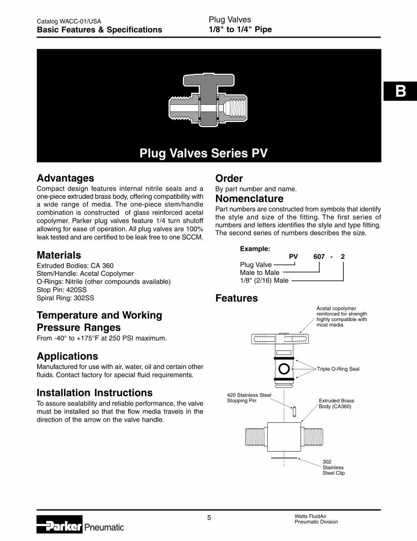
Triple O-Ring Seal
Extruded BrassBody (CA360)
420 Stainless SteelStopping Pin
Acetal copolymerreinforced for strengthhighly compatible with most media
302 Stainless Steel Clip
Plug Valves1/8" to 1/4" PipeBasic Features & Specifications
AdvantagesCompact design features internal nitrile seals and aone-piece extruded brass body, offering compatibility witha wide range of media. The one-piece stem/handlecombination is constructed of glass reinforced acetalcopolymer. Parker plug valves feature 1/4 turn shutoffallowing for ease of operation. All plug valves are 100%leak tested and are certified to be leak free to one SCCM.
MaterialsExtruded Bodies: CA 360Stem/Handle: Acetal CopolymerO-Rings: Nitrile (other compounds available)Stop Pin: 420SSSpiral Ring: 302SS
Temperature and WorkingPressure RangesFrom -40° to +175°F at 250 PSI maximum.
ApplicationsManufactured for use with air, water, oil and certain otherfluids. Contact factory for special fluid requirements.
Installation InstructionsTo assure sealability and reliable performance, the valvemust be installed so that the flow media travels in thedirection of the arrow on the valve handle.
OrderBy part number and name.
NomenclaturePart numbers are constructed from symbols that identifythe style and size of the fitting. The first series ofnumbers and letters identifies the style and type fitting.The second series of numbers describes the size.
Example:PV 607 - 2
Plug ValveMale to Male1/8" (2/16) Male
Features
Plug Valves Series PV

6 Watts FluidAirPneumatic Division
Pneumatic
Catalog WACC-01/USA Plug Valves1/8" to 1/4" PipePart Numbers & Dimensions
Male Pipe to Male Pipe Plug Valve PV607Part Pipe FlowNo. Thread H L M N N1 Dia. DPV607-2 1/8 .67 1.34 1.66 1.38 .51 .200PV607-4 1/4 .67 1.34 2.02 1.38 .51 .200
PV608 Female Pipe to Male Pipe Plug ValvePart Pipe FlowNo. Thread H L M N N1 Dia. DPV608-2 1/8 .67 1.34 1.67 1.38 .51 .200
PV608-4 1/4 .67 1.34 2.06 1.38 .51 .200
PV609 Female Pipe to Female Pipe Plug ValvePart Pipe FlowNo. Thread H L M N N1 Dia. DPV609-2 1/8 .67 1.34 1.68 1.38 .51 .200PV609-4 1/4 .67 1.34 2.10 1.38 .51 .200
L
N
H
N1
M
D
L
N
H
N1
M
D
L
N
H
N1
M
D
Watts FluidAirPneumatic Division
Pneumatic
C
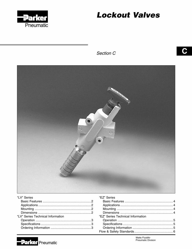
Lockout Valves
Section C
Pneumatic
“LV” SeriesBasic Features .......................................................2Applications ............................................................2Mounting ................................................................2Dimensions ............................................................2
“LV” Series Technical InformationOperation ...............................................................3Specifications .........................................................3Ordering Information ..............................................3
“EZ” SeriesBasic Features .......................................................4Applications ............................................................4Mounting ................................................................4Dimensions ............................................................4
“EZ” Series Technical InformationOperation ...............................................................5Specifications .........................................................5Ordering Information ..............................................5
Flow & Safety Standards............................................ 6
2 Watts FluidAirPneumatic Division
Pneumatic
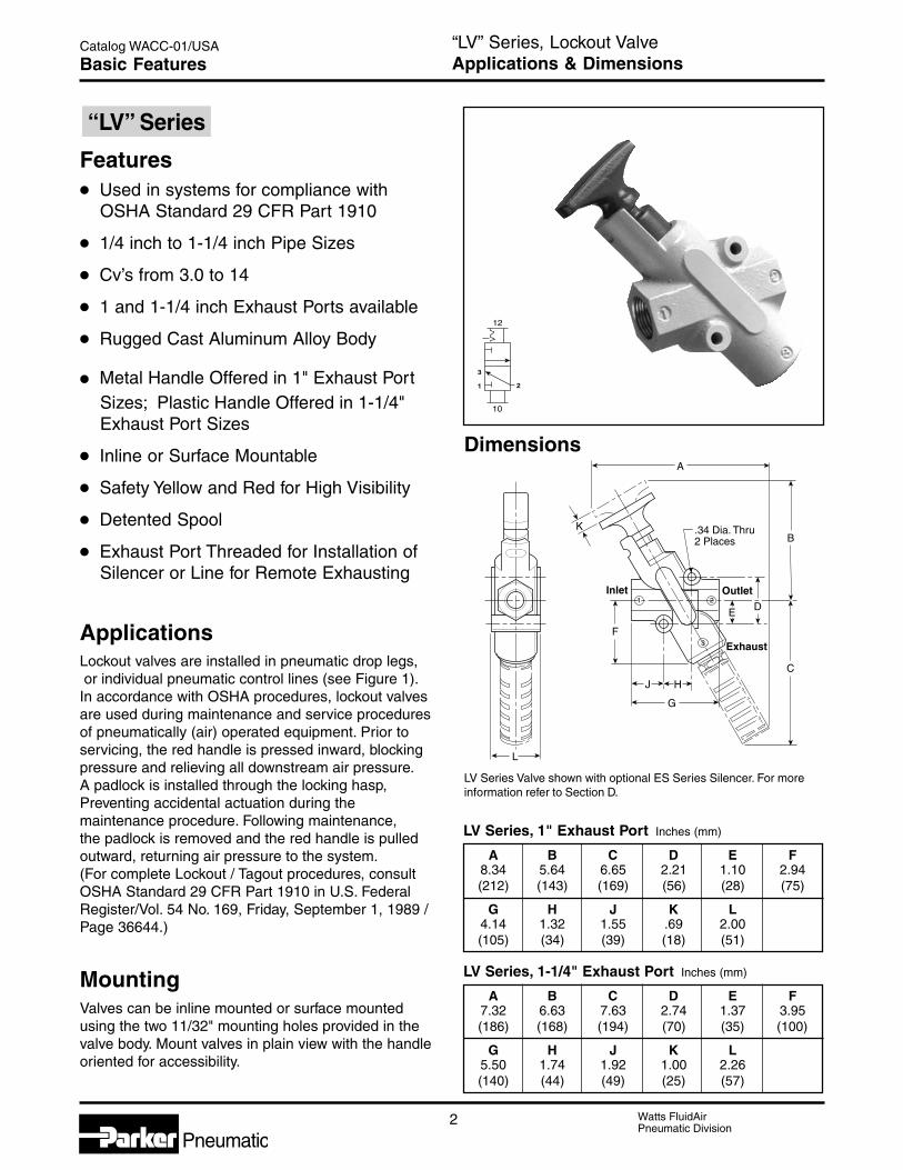
Catalog WACC-01/USA “LV” Series, Lockout ValveApplications & DimensionsBasic Features
Dimensions
J
L
D
B
F
C
E
G
A
K
H
Inlet Outlet
Exhaust
.34 Dia. Thru2 Places
1 2
3
Features• Used in systems for compliance with
OSHA Standard 29 CFR Part 1910
• 1/4 inch to 1-1/4 inch Pipe Sizes
• Cv’s from 3.0 to 14
• 1 and 1-1/4 inch Exhaust Ports available
• Rugged Cast Aluminum Alloy Body
• Metal Handle Offered in 1" Exhaust PortSizes; Plastic Handle Offered in 1-1/4"Exhaust Port Sizes
• Inline or Surface Mountable
• Safety Yellow and Red for High Visibility
• Detented Spool
• Exhaust Port Threaded for Installation ofSilencer or Line for Remote Exhausting
ApplicationsLockout valves are installed in pneumatic drop legs, or individual pneumatic control lines (see Figure 1).In accordance with OSHA procedures, lockout valvesare used during maintenance and service proceduresof pneumatically (air) operated equipment. Prior toservicing, the red handle is pressed inward, blockingpressure and relieving all downstream air pressure.A padlock is installed through the locking hasp,Preventing accidental actuation during themaintenance procedure. Following maintenance,the padlock is removed and the red handle is pulledoutward, returning air pressure to the system.(For complete Lockout / Tagout procedures, consultOSHA Standard 29 CFR Part 1910 in U.S. FederalRegister/Vol. 54 No. 169, Friday, September 1, 1989 /Page 36644.)
MountingValves can be inline mounted or surface mountedusing the two 11/32" mounting holes provided in thevalve body. Mount valves in plain view with the handleoriented for accessibility.
“LV” Series
LV Series, 1" Exhaust Port Inches (mm)
A B C D E F8.34 5.64 6.65 2.21 1.10 2.94(212) (143) (169) (56) (28) (75)
G H J K L4.14 1.32 1.55 .69 2.00(105) (34) (39) (18) (51)
LV Series, 1-1/4" Exhaust Port Inches (mm)
A B C D E F7.32 6.63 7.63 2.74 1.37 3.95(186) (168) (194) (70) (35) (100)
G H J K L5.50 1.74 1.92 1.00 2.26(140) (44) (49) (25) (57)
LV Series Valve shown with optional ES Series Silencer. For moreinformation refer to Section D.
10
12
1
3
2
3 Watts FluidAirPneumatic Division
Pneumatic
Catalog WACC-01/USA
C
“LV” Series, Lockout ValveOperation, Specifications & Ordering InfoTechnical Information
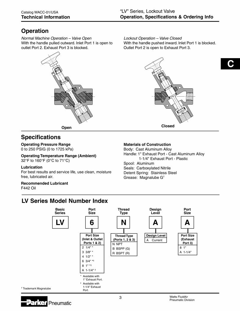
Port Size(Inlet & OutletPorts 1 & 2)
2 1/4" *
3 3/8" *4 1/2" *6 3/4" *‡
8 1" *‡
A 1-1/4" ‡
* Available with1" Exhaust Port.
‡ Available with1-1/4" ExhaustPort.
Basic Port Thread Design PortSeries Size Type Level Size
LV 6 N A A
Thread Type(Ports 1, 2 & 3)N NPTB BSPP (G)
R BSPT (R)
Port Size(ExhaustPort 3)
8 1"A 1-1/4"
Design LevelA Current
LV Series Model Number Index
OperationNormal Machine Operation – Valve OpenWith the handle pulled outward. Inlet Port 1 is open tooutlet Port 2. Exhaust Port 3 is blocked.
Open
Lockout Operation – Valve ClosedWith the handle pushed inward. Inlet Port 1 is blocked.Outlet Port 2 is open to Exhaust Port 3.
Closed
† Trademark Magnalube
SpecificationsOperating Pressure Range0 to 250 PSIG (0 to 1725 kPa)
Operating Temperature Range (Ambient)32°F to 160°F (0°C to 71°C)
LubricationFor best results and service life, use clean, moisturefree, lubricated air.
Recommended LubricantF442 Oil
Materials of ConstructionBody: Cast Aluminum AlloyHandle: 1" Exhaust Port - Cast Aluminum Alloy
1-1/4" Exhaust Port - PlasticSpool: AluminumSeals: Carboxylated NitrileDetent Spring: Stainless SteelGrease: Magnalube G†

4 Watts FluidAirPneumatic Division
Pneumatic
Catalog WACC-01/USA
Features• Combines Lockout and Soft-Start
Functions in a Single Unit
• Used in systems for compliance withOSHA Standard 29 CFR Part 1910
• 3/8 inch to 1-1/4 inch Pipe Sizes
• Cv’s from 3.7 to 13.7
• 3/4 and 1-1/4 inch: Exhaust Ports available
• Rugged Cast Aluminum Alloy Body
• Exhaust Port Threaded for Installation ofSilencer or Line for Remote Exhausting
• Inline or Surface Mountable
ApplicationsEZ valves are installed in pneumatic drop legs,or individual pneumatic control lines (see Figure 1).In accordance with OSHA procedures, EZ valves areused during maintenance and service procedures ofpneumatically (air) operated equipment. Prior toservicing, the blue handle is pressed inward, blockingpressure and relieving all downstream air pressure.A padlock is installed through the locking hasp,preventing accidental actuation during themaintenance procedure. Following maintenance,the padlock is removed and the blue handle is pulledoutward, gradually returning air pressure to thesystem. (For complete Lockout / Tagout procedures,consult OSHA Standard 29 CFR Part 1910 in U.S.Federal Register/Vol. 54 No. 169, Friday, September 1,1989 /Page 36644.)
MountingValves can be inline mounted or surface mountedusing the two 11/32" mounting holes provided in thevalve body. Mount valves in plain view with the handleoriented for accessibility.
EZ Series Valve shown with optional ES Series Silencer. For moreinformation refer to Section D.
“EZ” Series, Lockout ValveApplications & DimensionsBasic Features
“EZ” Series
L
K
J
G
H
D
F
E
Inlet Outlet
Exhaust
B
C
A
.34 Dia. Thru2 Places
1 2
3
Dimensions
EZ Series, 1-1/4" Exhaust Port Inches (mm)
A B C D E F7.32 6.63 7.63 2.74 1.37 3.95(186) (168) (194) (70) (35) (100)
G H J K L5.50 1.74 1.92 1.00 2.26(140) (44) (49) (25) (57)
EZ Series, 3/4" Exhaust Port Inches (mm)
A B C D E F6.26 5.78 6.25 2.20 1.10 2.97(159) (147) (159) (56) (28) (75)
G H J K L4.36 1.32 1.44 .80 2.02(111) (34) (37) (20) (51)
10
12
1
3
2

5 Watts FluidAirPneumatic Division
Pneumatic
Catalog WACC-01/USA
C
SpecificationsOperating Pressure Range30 to 150 PSIG (2 to 10 bar)Open to Full Flow: Inlet Pressure - 25 PSIG (1.7 bar)
Operating Temperature Range (Ambient)40°F to 175°F (4°C to 80°C)
LubricationFor best results and service life, use clean, moisturefree, lubricated air.
Recommended LubricantF442 Oil
Materials of ConstructionBody: Cast Aluminum AlloyHandle: PlasticSpool: AluminumSeals: Carboxylated NitrileDetent Spring: Stainless SteelGrease: Magnalube G†
“EZ” Series, Lockout ValveOperation, Specifications & Ordering InfoTechnical Information
EZ Combination EEZ-On Series Model Number Index
OperationNormal Machine Operation – Valve OpenWhen the blue handle is pulled outward, the adjustableneedle valve (accessed through the top of the handle)setting determines the rate of pressure buildup. Whendownstream pressure reaches the full flow describedin the specifications below, Inlet Port 1 is open tooutlet Port 2. Exhaust Port 3 is blocked.
Lockout Operation – Valve ClosedWhen the blue handle is pushed inward, the Inlet Port 1 is blocked. Downstream air is exhaustedthrough Exhaust Port 3.
Closed
Port Size(Inlet & OutletPorts 1 & 2)
03 3/8" *
04 1/2" *
06 3/4" *‡
08 1" ‡
0A 1-1/4" ‡
Basic Port Thread Design PortSeries Size Type Level Size
EZ 03 N B A
Thread Type(Ports 1, 2 & 3)N NPT
B BSPP (G)R BSPT (R)
Port Size(ExhaustPort 3)
6 3/4"A 1-1/4"
Design LevelB Current
OpenFull Flow
OpenPressure Building Up
Notes:
* Available with3/4" Exhaust Port.
‡ Available with1-1/4" Exhaust Port.
† Trademark Magnalube
(Revised 10/25/04)

6 Watts FluidAirPneumatic Division
Pneumatic
Catalog WACC-01/USA “EZ” & “LV” Series, Lockout ValvesFlow & Safety StandardsTechnical Information
FRL
Main AirPressure
ToRequirement
ToRequirement
10
12
1
3
2
10
12
1
3
2
Figure 1Lockout Valves Shown In The
Passing Condition
Friday, September 1, 1989 the Occupational Safety andHealth Administration (OSHA) passed a standard,29CFR Part 1910, requiring certain lockout and / ortagout procedures for the control of a hazardous energysource. This standard addresses practices andprocedures that are necessary to disable the release ofpotentially hazardous energy while maintenance andservicing activities are being performed. Tagout refers tothe use of tags to warn workers when equipment usingpotentially hazardous energy is being serviced. Lockoutis the procedure which ensures that all power to a pieceof equipment is isolated, locked or blocked anddissipated using a method that cannot be readilyremoved to bypassed. Dissipation means stored energyat the equipment is brought to a neutral state. Thisstandard is expected to save 120 lives and prevent60,000 accidents a year. This OSHA Standard becameeffective October 31, 1989.
A typical application (Figure 1) shows a main lockoutvalve mounted in the main drop leg, before the split tomachine functions. Additional lockout valves can be usedto isolate individual control lines. Before servicing, thevalve can be actuated and locked to isolate downstreamfrom pressure, and exhaust downstream to atmospherethus making equipment safe for maintenance.
To reference this standard see the U.S. Federal Register/ Vol. 54, No. 169 / Friday, September 1, 1989 / Page36644. For copies of this standard, contact U.S.Department of Labor, Occupational Safety and HealthAdministration, Office of Publication, Room N3101,Washington, DC 20210, (202) 523-9667.
Schematic
FlowModel 1 to 2 Cv 2 to 3 Cv
LV2NA8 3.00 6.00
LV3NA8 4.30 9.00
LV4NA8 7.70 11.30
LV6NA8 9.50 9.00
LV6NAA 13.98 10.90
LV8NA8 10.20 8.80
LV8NAA 16.70 9.86
LVANAA 19.71 10.41
Model 1 to 2 Cv 2 to 3 Cv
EZ03NB6 3.79 3.78
EZ04NB6 5.31 3.77
EZ06NBA 6.01 9.25
EZ08NBA 11.18 8.13
EZ0ANBA 13.74 8.03
(Revised 10/25/04)

D
Watts FluidAirPneumatic Division
Pneumatic
Flow Controls& Accessories
Section D
Pneumatic
Flow Control Valves“SPF” Series ..........................................................2“337” Series ...........................................................3“3250” Series ..................................................... 4-5Right Angle Series ............................................. 6-9
Needle Valves“SPN” Series ........................................................10“338” Series .........................................................11“SPC” Series Check Valve ...................................12
“339” & “3047” Series Check Valve ..................... 13“EM” Series Exhaust Mufflers .............................. 14Breather Vents ..................................................... 15“ES” Series Silencer............................................. 15ASN Air Line Silencer .......................................... 16Muffler-Reclassifier ECS ...................................... 17Automatic Drip Leg Drain .....................................18Relief Valves ........................................................ 18Quick Exhaust & Shuttle Valves .................... 19-21

2 Watts FluidAirPneumatic Division
Pneumatic
Catalog WACC-01/USA Flow Controls & Accessories“SPF” Series – 1/8" to 1/2" PortsFlow Control Valves
EC
F
D
B(Open)
A(Both Ends)
Valve SpecificationsMaximum Operating Pressure2000 PSI Non-Shock
Cracking pressure for return check poppet –5 PSI Nominal
Operating TemperatureStandard: 0° to 140° F*
-40° to 140° F (Hydraulic service)
Extended Temperature: 0° to 400°F** Ambient temperatures below freezing require moisture-free air.
Ambient temperatures below freezing and above 180° requirelubricants especially selected for suitability at thesetemperatures. Pneumatic valves should be used with filteredand lubricated air.
General InformationThe “SPF” Series Flow Control Valves meter flow ofair or oil in one direction and allow free flow in thereverse direction.
“SPF” Series valves are manufactured with a two stepneedle. Fine metering is accomplished over the initialadjustment turns and nominal metering is providedover the remaining turns. Once the desired flow isselected, a set screw can be tightened to maintain thesetting.
These valves are available with NPTF ports in 1/8",1/4", 3/8", and 1/2" sizes.
Component MaterialsBody Material: Brass
Needle: Stainless Steel
Ball Check: Stainless Steel
Check Retainer: Acetal
Needle Seals: Nitrile (Standard),Fluorocarbon (Optional)
Knob: Aluminum
Model Selection and Dimensions
For units with Fluorocarbon seals, add suffix “V”. Example: SPF200BV
ModelNumber A Port Size B C D E F
SPF200B 1/8-27 NPTF 1.50 1.75 .625 1.06 .75
SPF400B 1/4-18 NPTF 1.80 2.38 .812 1.41 .81
SPF600B 3/8-18 NPTF 2.25 2.75 1.000 1.75 1.00
SPF800B 1/2-14 NPTF 2.72 3.19 1.250 2.06 1.19
Controlled Flow Free FlowNeedle Full Open/Check Closed Needle Full Open
Model Flow - SCFM Effective Flow - SCFM EffectiveNumber @ 100 PSI Cv Area @ 100 PSI Cv Area
Full DP Sq. Inches Full DP Sq. Inches
SPF200B 8.8 .16 .006 25.4 .46 .018
SPF400B 19.3 .35 .013 55.2 1.00 .038
SPF600B 33.1 .60 .023 99.3 1.80 .070
SPF800B 55.2 1.00 .038 138.0 2.50 .096
Performance Data - Flow
3 Watts FluidAirPneumatic Division
Pneumatic
Catalog WACC-01/USA
C
D
Flow Controls & Accessories“337” Series – 1/8" to 3/4" PortsMicrometer Flow Control Valves
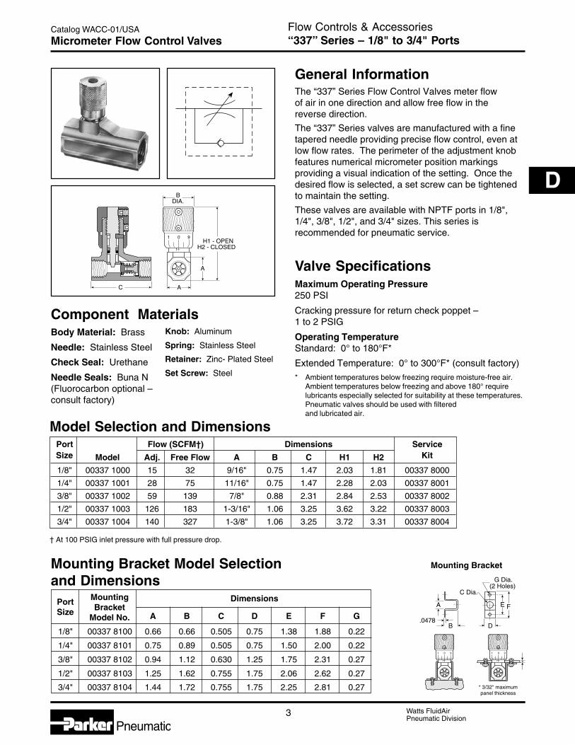
Port Flow (SCFM†) Dimensions ServiceSize Model Adj. Free Flow A B C H1 H2 Kit
1/8" 00337 1000 15 32 9/16" 0.75 1.47 2.03 1.81 00337 8000
1/4" 00337 1001 28 75 11/16" 0.75 1.47 2.28 2.03 00337 8001
3/8" 00337 1002 59 139 7/8" 0.88 2.31 2.84 2.53 00337 8002
1/2" 00337 1003 126 183 1-3/16" 1.06 3.25 3.62 3.22 00337 8003
3/4" 00337 1004 140 327 1-3/8" 1.06 3.25 3.72 3.31 00337 8004
† At 100 PSIG inlet pressure with full pressure drop.
General InformationThe “337” Series Flow Control Valves meter flowof air in one direction and allow free flow in thereverse direction.
The “337” Series valves are manufactured with a finetapered needle providing precise flow control, even atlow flow rates. The perimeter of the adjustment knobfeatures numerical micrometer position markingsproviding a visual indication of the setting. Once thedesired flow is selected, a set screw can be tightenedto maintain the setting.
These valves are available with NPTF ports in 1/8",1/4", 3/8", 1/2", and 3/4" sizes. This series isrecommended for pneumatic service.
Valve SpecificationsMaximum Operating Pressure250 PSI
Cracking pressure for return check poppet –1 to 2 PSIG
Operating TemperatureStandard: 0° to 180°F*
Extended Temperature: 0° to 300°F* (consult factory)* Ambient temperatures below freezing require moisture-free air.
Ambient temperatures below freezing and above 180° requirelubricants especially selected for suitability at these temperatures.Pneumatic valves should be used with filteredand lubricated air.
Model Selection and Dimensions
Mounting Bracket Model Selectionand Dimensions
Body Material: Brass
Needle: Stainless Steel
Check Seal: Urethane
Needle Seals: Buna N(Fluorocarbon optional –consult factory)
Knob: Aluminum
Spring: Stainless Steel
Retainer: Zinc- Plated Steel
Set Screw: Steel
Mounting Bracket
BDIA.
AC
H1 - OPENH2 - CLOSED
A
1
1
0 9
* 3/32" maximumpanel thickness
C Dia.
B
E
G Dia.(2 Holes)
FA
.0478D
*
1
1
0 9 1
1
0 9
Port Mounting Dimensions
Size BracketModel No. A B C D E F G
1/8" 00337 8100 0.66 0.66 0.505 0.75 1.38 1.88 0.22
1/4" 00337 8101 0.75 0.89 0.505 0.75 1.50 2.00 0.22
3/8" 00337 8102 0.94 1.12 0.630 1.25 1.75 2.31 0.27
1/2" 00337 8103 1.25 1.62 0.755 1.75 2.06 2.62 0.27
3/4" 00337 8104 1.44 1.72 0.755 1.75 2.25 2.81 0.27
Component Materials
4 Watts FluidAirPneumatic Division
Pneumatic
Catalog WACC-01/USA Flow Controls & Accessories“3250” Series – 1/8" to 3/4" PortsFlow Control Valves
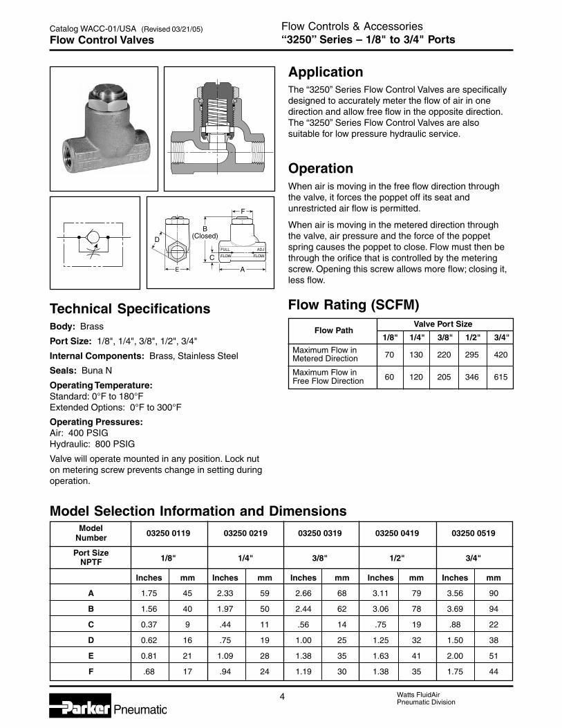
ApplicationThe “3250” Series Flow Control Valves are specificallydesigned to accurately meter the flow of air in onedirection and allow free flow in the opposite direction.The “3250” Series Flow Control Valves are alsosuitable for low pressure hydraulic service.
OperationWhen air is moving in the free flow direction throughthe valve, it forces the poppet off its seat andunrestricted air flow is permitted.
When air is moving in the metered direction throughthe valve, air pressure and the force of the poppetspring causes the poppet to close. Flow must then bethrough the orifice that is controlled by the meteringscrew. Opening this screw allows more flow; closing it,less flow.
Flow Rating (SCFM)
Flow PathValve Port Size
1/8" 1/4" 3/8" 1/2" 3/4"
Maximum Flow in 70 130 220 295 420Metered Direction
Maximum Flow in 60 120 205 346 615Free Flow Direction
Model Selection Information and DimensionsModel
03250 0119 03250 0219 03250 0319 03250 0419 03250 0519Number
Port Size1/8" 1/4" 3/8" 1/2" 3/4"NPTF
Inches mm Inches mm Inches mm Inches mm Inches mm
A 1.75 45 2.33 59 2.66 68 3.11 79 3.56 90
B 1.56 40 1.97 50 2.44 62 3.06 78 3.69 94
C 0.37 9 .44 11 .56 14 .75 19 .88 22
D 0.62 16 .75 19 1.00 25 1.25 32 1.50 38
E 0.81 21 1.09 28 1.38 35 1.63 41 2.00 51
F .68 17 .94 24 1.19 30 1.38 35 1.75 44
E
F
D
A
CFULL
FLOW
ADJ
FLOW
B(Closed)
Technical SpecificationsBody: Brass
Port Size: 1/8", 1/4", 3/8", 1/2", 3/4"
Internal Components: Brass, Stainless Steel
Seals: Buna N
Operating Temperature:Standard: 0°F to 180°FExtended Options: 0°F to 300°F
Operating Pressures:Air: 400 PSIGHydraulic: 800 PSIG
Valve will operate mounted in any position. Lock nuton metering screw prevents change in setting duringoperation.
(Revised 03/21/05)

5 Watts FluidAirPneumatic Division
Pneumatic
Catalog WACC-01/USA
C
D
Flow Controls & Accessories“3250” Series – 1", 1-1/4" & 1-1/2" PortsFlow Control Valves
ApplicationThese extra large flow control valves have beendeveloped to provide effective flow settings forlarge diameter cylinders and for other similar airapplications. Each valve has a fine screw adjustmentallowing precise settings which are secured bya sturdy lock nut.
OperationLarge internal port passages coupled with unique softseal poppet and inline design provide maximum fullflow capacity and minimum pressure drop in the freeflow direction. Their cone shaped brass metering valvewill provide consistent cylinder speed by regulatingcylinder exhaust.
Flow Capacity InFull Flow Direction
Port Max. FlowModelSize (Needle Open)
Number(NPTF) SCFM** Cv1 1000 12.3 03250 1000
1-1/4 1200 13.8 03250 1250
1-1/2 1800 17.5 03250 1500
** At 100 PSIG inlet pressure with full pressure drop.
Model Selection Information andDimensionsModel Number 03250 1000 03250 1250 03250 1500
Port Size1" 1-1/4" 1-1/2"NPTF
Inches mm Inches mm Inches mm
A 5.00 127 5.00 127 5.88 149
B 6.50 165 6.50 165 8.00 203
C 3.00 76 3.00 76 3.75 95
D 3.25 83 3.25 83 3.50 89
E 2.25 57 2.25 57 2.50 64
F .39 10 .39 10 .39 10
G 1.31 33 1.31 33 1.50 38
H 2.13 54 2.13 54 2.38 60
D
A
F
C
G
E
H(Hex)
FullFlow
AdjFlowB
(Closed)
Technical SpecificationsBody: Cast Aluminum
Port Size: 1", 1-1/4", 1-1/2"
Internal Components: Brass, Aluminum
Seals: Buna N, Urethane
Spring: Stainless Steel
Operating Temperature:Standard: – 40°F to 180°FExtended Options: – 40°F to 350°F
Operating Pressures:Maximum Air: 250 PSIG
6 Watts FluidAirPneumatic Division
Pneumatic
Catalog WACC-01/USA
H
C
LM
D
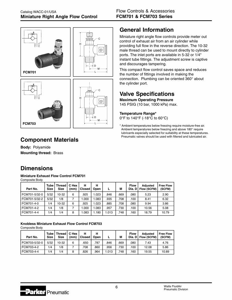
Flow Controls & AccessoriesFCM701 & FCM703 SeriesMiniature Right Angle Flow Control
H
C
LM
D
General InformationMiniature right angle flow controls provide meter outcontrol of exhaust air from an air cylinder whileproviding full flow in the reverse direction. The 10-32male thread can be used to mount directly to cylinderports. The inlet ports are available in 5-32 or 1/4"instant tube fittings. The adjustment screw is captiveand discourages tampering.
This compact flow control saves space and reducesthe number of fittings involved in making theconnection. Plumbing can be oriented 360° aboutthe cylinder port.
Valve SpecificationsMaximum Operating Pressure145 PSIG (10 bar, 1000 kPa) max.
Temperature Range*0°F to 140°F (-18°C to 60°C)
* Ambient temperatures below freezing require moisture-free air.Ambient temperatures below freezing and above 180° requirelubricants especially selected for suitability at these temperatures.Pneumatic valves should be used with filtered and lubricated air.
DimensionsMiniature Exhaust Flow Control FCM701Composite Body
FCM701
FCM703
Tube Thread C Hex H H Flow Adjusted Free FlowPart No. Size Size (mm) Closed Open L M Dia. D Flow (SCFM) (SCFM)
FCM701-5/32-0 5/32 10-32 6 .925 1.023 .846 .669 .080 5.23 2.90
FCM701-5/32-2 5/32 1/8 7 1.000 1.083 .935 .708 .100 8.41 6.32
FCM701-4-0 1/4 10-32 6 .925 1.023 .885 .708 .080 9.94 3.86
FCM701-4-2 1/4 1/8 7 1.000 1.083 .957 .730 .100 10.56 5.08
FCM701-4-4 1/4 1/4 8 1.083 1.180 1.013 .748 .160 18.79 10.79
Knobless Miniature Exhaust Flow Control FCM703Composite Body
Tube Thread C Hex H H Flow Adjusted Free FlowPart No. Size Size (mm) Closed Open L M Dia. D Flow (SCFM) (SCFM)
FCM703-5/32-0 5/32 10-32 6 .650 .787 .846 .669 .080 7.43 4.76
FCM703-4-2 1/4 1/8 7 .708 .860 .956 .730 .100 12.08 5.86
FCM703-4-4 1/4 1/4 8 .826 .964 1.013 .748 .160 19.55 10.89
Component MaterialsBody: Polyamide
Mounting thread: Brass
7 Watts FluidAirPneumatic Division
Pneumatic
Catalog WACC-01/USA
C
D
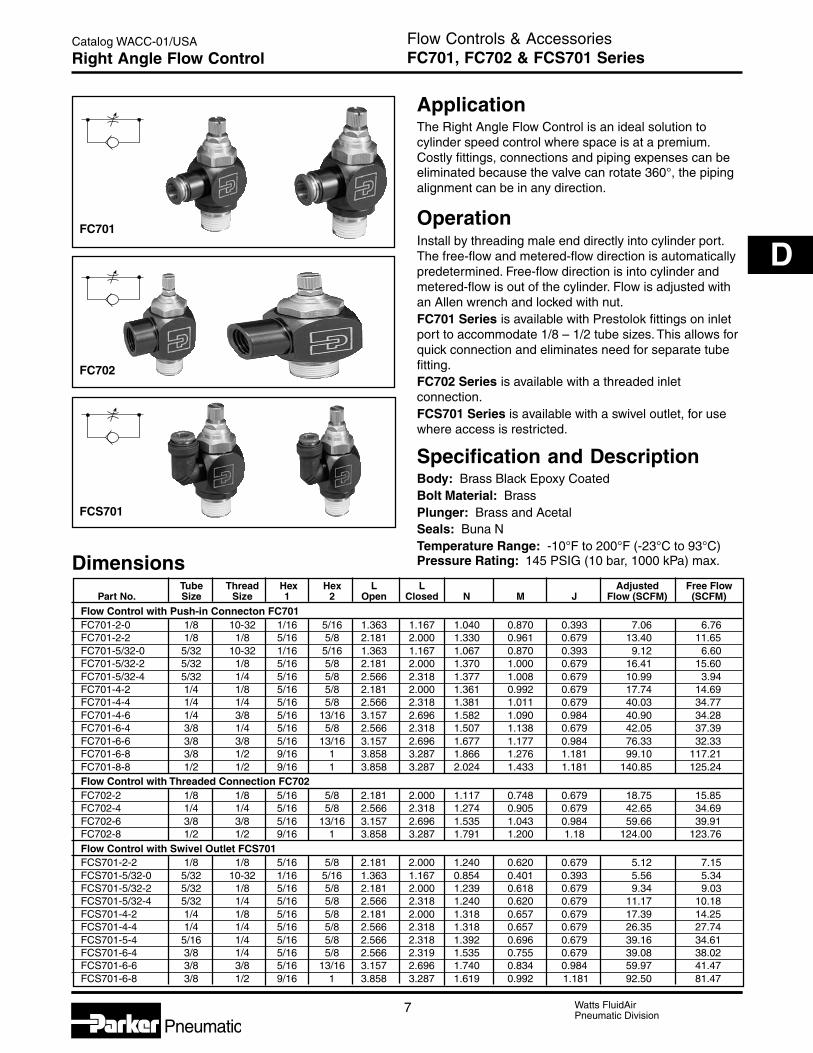
Flow Controls & AccessoriesFC701, FC702 & FCS701 SeriesRight Angle Flow Control
ApplicationThe Right Angle Flow Control is an ideal solution tocylinder speed control where space is at a premium.Costly fittings, connections and piping expenses can beeliminated because the valve can rotate 360°, the pipingalignment can be in any direction.
OperationInstall by threading male end directly into cylinder port.The free-flow and metered-flow direction is automaticallypredetermined. Free-flow direction is into cylinder andmetered-flow is out of the cylinder. Flow is adjusted withan Allen wrench and locked with nut.FC701 Series is available with Prestolok fittings on inletport to accommodate 1/8 – 1/2 tube sizes. This allows forquick connection and eliminates need for separate tubefitting.FC702 Series is available with a threaded inletconnection.FCS701 Series is available with a swivel outlet, for usewhere access is restricted.
Specification and DescriptionBody: Brass Black Epoxy CoatedBolt Material: BrassPlunger: Brass and AcetalSeals: Buna NTemperature Range: -10°F to 200°F (-23°C to 93°C)Pressure Rating: 145 PSIG (10 bar, 1000 kPa) max.Dimensions
Tube Thread Hex Hex L L Adjusted Free FlowPart No. Size Size 1 2 Open Closed N M J Flow (SCFM) (SCFM)
Flow Control with Push-in Connecton FC701FC701-2-0 1/8 10-32 1/16 5/16 1.363 1.167 1.040 0.870 0.393 7.06 6.76FC701-2-2 1/8 1/8 5/16 5/8 2.181 2.000 1.330 0.961 0.679 13.40 11.65FC701-5/32-0 5/32 10-32 1/16 5/16 1.363 1.167 1.067 0.870 0.393 9.12 6.60FC701-5/32-2 5/32 1/8 5/16 5/8 2.181 2.000 1.370 1.000 0.679 16.41 15.60FC701-5/32-4 5/32 1/4 5/16 5/8 2.566 2.318 1.377 1.008 0.679 10.99 3.94FC701-4-2 1/4 1/8 5/16 5/8 2.181 2.000 1.361 0.992 0.679 17.74 14.69FC701-4-4 1/4 1/4 5/16 5/8 2.566 2.318 1.381 1.011 0.679 40.03 34.77FC701-4-6 1/4 3/8 5/16 13/16 3.157 2.696 1.582 1.090 0.984 40.90 34.28FC701-6-4 3/8 1/4 5/16 5/8 2.566 2.318 1.507 1.138 0.679 42.05 37.39FC701-6-6 3/8 3/8 5/16 13/16 3.157 2.696 1.677 1.177 0.984 76.33 32.33FC701-6-8 3/8 1/2 9/16 1 3.858 3.287 1.866 1.276 1.181 99.10 117.21FC701-8-8 1/2 1/2 9/16 1 3.858 3.287 2.024 1.433 1.181 140.85 125.24Flow Control with Threaded Connection FC702FC702-2 1/8 1/8 5/16 5/8 2.181 2.000 1.117 0.748 0.679 18.75 15.85FC702-4 1/4 1/4 5/16 5/8 2.566 2.318 1.274 0.905 0.679 42.65 34.69FC702-6 3/8 3/8 5/16 13/16 3.157 2.696 1.535 1.043 0.984 59.66 39.91FC702-8 1/2 1/2 9/16 1 3.858 3.287 1.791 1.200 1.18 124.00 123.76Flow Control with Swivel Outlet FCS701FCS701-2-2 1/8 1/8 5/16 5/8 2.181 2.000 1.240 0.620 0.679 5.12 7.15FCS701-5/32-0 5/32 10-32 1/16 5/16 1.363 1.167 0.854 0.401 0.393 5.56 5.34FCS701-5/32-2 5/32 1/8 5/16 5/8 2.181 2.000 1.239 0.618 0.679 9.34 9.03FCS701-5/32-4 5/32 1/4 5/16 5/8 2.566 2.318 1.240 0.620 0.679 11.17 10.18FCS701-4-2 1/4 1/8 5/16 5/8 2.181 2.000 1.318 0.657 0.679 17.39 14.25FCS701-4-4 1/4 1/4 5/16 5/8 2.566 2.318 1.318 0.657 0.679 26.35 27.74FCS701-5-4 5/16 1/4 5/16 5/8 2.566 2.318 1.392 0.696 0.679 39.16 34.61FCS701-6-4 3/8 1/4 5/16 5/8 2.566 2.319 1.535 0.755 0.679 39.08 38.02FCS701-6-6 3/8 3/8 5/16 13/16 3.157 2.696 1.740 0.834 0.984 59.97 41.47FCS701-6-8 3/8 1/2 9/16 1 3.858 3.287 1.619 0.992 1.181 92.50 81.47
FCS701
FC702
FC701

8 Watts FluidAirPneumatic Division
Pneumatic
Catalog WACC-01/USA Flow Controls & AccessoriesM5 (10-32) PortMiniature Right Angle Flow Control
Valve SpecificationsMaximum Operating Pressure145 PSIG (10 bar)
Operating Temperature0° to 140°F*
* Ambient temperatures below freezing require moisture-free air.Ambient temperatures below freezing and above 180° requirelubricants especially selected for suitability at these temperatures.Pneumatic valves should be used with filtered and lubricated air.
General InformationMiniature right angle flow controls provide meter outcontrol of exhaust air from an air cylinder whileproviding full flow in the reverse direction. TheM5 (10-32) male thread can be used to mountdirectly to cylinder ports. The inlet ports areavailable in M5 (10-32) male or 5/32" instant tubefitting. The adjustment screw is captive anddiscourages tampering.
This compact flow control saves space and reducesthe number of fittings involved in making theconnection. Plumbing can be oriented 360°about the cylinder port.
Component MaterialsBody: Polyamide
Mounting thread: Brass
Model Selection
Dimensions - Inches (mm)
Flow
Ports Wrench Model NumberMale Female Size
M5 M5 5/16" PWRE14557
M5 5/32" Tube 5/16" PWRE14457
Note: Standard 10-32 fittings will fit the M5 threads on valve body.
A
L
K
C
H
3mm Dia.
A C K H L.43 .16 .28 .67 .79(11) (4) (7,2) (17) (20)
No of Exhaust InletTurns (Screw Open) (Screw Closed)
12 1.8 SCFM 1.8 SCFM

9 Watts FluidAirPneumatic Division
Pneumatic
Catalog WACC-01/USA
C
D
Flow Controls & Accessories“3251” SeriesHeavy Duty Right Angle Flow Control
ApplicationThe Heavy Duty Right Angle Flow Control is an idealsolution to cylinder speed control where space is ata premium. Costly fittings, connections and pipingexpenses can be eliminated because the valve canrotate 360°, the piping alignment can be in any direction.The 1/8" model can be rotated after final assembly.
OperationInstall by threading male end directly into cylinderport. The free-flow and metered-flow direction isautomatically predetermined. Free-flow direction isinto cylinder and metered-flow is out of the cylinder.Flow is adjusted with an Allen wrench and lockedwith nut.
Heavy Duty Right Angle Flow Control also availablewith Prestolok fittings on inlet port to accommodate5/32 - 3/8 tube sizes. This allows for quick connectionand eliminates need for separate tube fitting.
Specification and DescriptionBody: Brass
Plunger: Brass and Acetal
Seals: Buna N
Temperature Range: 0°F to 140°F (–18°C to 60°C)Pressure Rating: 125 PSIG (863 kPa) max.
Shown withThreaded Inlet
Shown with PrestolokInlet Fitting
C
AOpen
BB1
Metered Flow
FreeFlow
Model Selection Information and DimensionsModel Thread Thread A B C Weight Cv
Number (NPT) (NPT) Adjusted FreeMale Female Inches mm Inches mm Inches mm oz. kg. Flow Flow
03251 0125 1/8 1/8 1.63 41 1.18 30 .67 17 2.0 0.9 0.26 0.20
03251 0250 1/4 1/4 1.86 47 1.40 36 .91 23 4.5 2.0 0.75 0.68
03251 0375 3/8 3/8 2.15 55 1.71 43 1.06 27 7.0 3.2 0.84 0.72
03251 0500 1/2 1/2 2.54 65 1.98 53 1.26 32 11.0 5.0 1.64 1.41
With Prestolok Thread TubeA B1 C Weight Cv
Fittings (NPT) Size
03251 1215 1/8 5/32 1.63 41 1.18 30 .67 17 2.0 0.9 0.19 0.16
03251 1225 1/8 1/4 1.63 41 1.18 30 .67 17 2.0 0.9 0.28 0.22
03251 2525 1/4 1/4 1.86 47 1.40 36 .91 23 4.5 2.0 0.51 0.44
03251 2538 1/4 3/8 1.86 47 1.40 36 .91 23 4.5 2.0 0.62 0.53
03251 3838 3/8 3/8 2.15 55 1.71 43 1.06 27 7.0 3.2 0.78 0.65
CAUTION: If it is possible that the ambient temperature may fall below freezing, the medium must be moisture-free to prevent internaldamage or unpredictable behavior.
!

10 Watts FluidAirPneumatic Division
Pneumatic
Catalog WACC-01/USA Flow Controls & Accessories“SPN” Series – 1/8" to 1/2" PortsNeedle Valves
General InformationThe “SPN” Series needle valves provide excellentbi-directional speed control for pneumatic andhydraulic applications.
“SPN” valves are manufactured with a two step needle.Fine metering is accomplished over the initialadjustment turns and nominal metering is providedover the remaining turns. Once the desired flow isselected, a set screw can be tightened to maintainthe setting.
These valves are available with NPTF ports in 1/8",1/4", 3/8" and 1/2" sizes.
Valve SpecificationsMaximum Operating Pressure2000 PSI Non-Shock
Operating TemperatureStandard: 0° to 140° F*
Extended temperature: 0° to 400°F** Ambient temperatures below freezing require moisture-free air.
Ambient temperatures below freezing and above 180° requirelubricants especially selected for suitability at these temperatures.Pneumatic valves should be used with filtered and lubricated air.
Component MaterialsBody: Brass
Needle: Stainless Steel
Needle seals: Nitrile (Standard),Fluorocarbon (Optional)
Knob: Aluminum
For units with Fluorocarbon seals, add suffix “V”. Example: SPN200BV
ModelNumber A Port Size B C D E F
SPN200B 1/8-27 NPTF 1.50 1.50 .625 .75 .75
SPN400B 1/4-18 NPTF 1.80 2.00 .812 1.00 .81
SPN600B 3/8-18 NPTF 2.25 2.25 1.000 1.13 1.00
SPN800B 1/2-14 NPTF 2.72 2.62 1.250 1.31 1.19
Model Selection and Dimensions
Controlled FlowNeedle Full Open
Model Flow - SCFMNumber @ 100 PSI Cv
Area
Full DP Sq. Inches
SPN200B 8.8 .16 .006
SPN400B 19.3 .35 .013
SPN600B 33.1 .60 .023
SPN800B 55.2 1.00 .038
Performance Data
EC
F
D
B(Open)
A(Both Ends)

11 Watts FluidAirPneumatic Division
Pneumatic
Catalog WACC-01/USA
C
D
Flow Controls & Accessories“338” Series – 1/8" to 3/4" PortsNeedle Valves
† At 100 PSIG inlet pressure with full pressure drop.
Component MaterialsBody Material: Brass
Internal Components: Stainless Steel/Brass
Seals: Nitrile (Fluorocarbon optional – consult factory)
Model Selection and Dimensions
Valve SpecificationsMaximum Operating Pressure250 PSIG (Air)
Operating TemperatureStandard: 0° to 180° F*
Extended Temperature: 0°F to 300°F*(Consult factory)
* Ambient temperatures below freezing require moisture-free air.Ambient temperatures below freezing and above 180° requirelubricants especially selected for suitability at these temperatures.Pneumatic valves should be used with filtered and lubricated air.
Performance Data – Flow
General Information“338” Series needle valves bi-directionally meter theflow of air through the valve.
This series features a fine tapered needle providingprecise flow of air in both directions. Numericalmicrometer position markings are stamped on theperimeter of the adjustment knob which provide avisual indication of the setting. Once the desired flowis selected, a set screw can be tightened to maintainthe setting.
These valves are available with NPTF ports in 1/8",1/4", 3/8" 1/2" and 3/4" sizes. This series isrecommended for pneumatic service.
O-ring forfriction 1
1
0 9
C
BDIA.
A
H1 - OPENH2 - CLOSED
A
Port Dimensions ServiceSize Model A B C H1 H2 Kit
1/8" 00338 1100 9/16" 0.75 1.47 2.03 1.81 00337 8000
1/4" 00338 1101 11/16" 0.75 1.47 2.28 2.03 00337 8001
3/8" 00338 1102 7/8" 0.88 2.31 2.84 2.53 00337 8002
1/2" 00338 1103 1-3/16" 1.06 3.25 3.62 3.22 00337 8003
3/4" 00338 1104 1-3/8" 1.06 3.25 3.72 3.31 00337 8004
Port Model FlowSize Number (SCFM†)
1/8" 00338 1100 15
1/4" 00338 1101 28
3/8" 00338 1102 59
1/2" 00338 1103 126
3/4" 00338 1104 140
12 Watts FluidAirPneumatic Division
Pneumatic
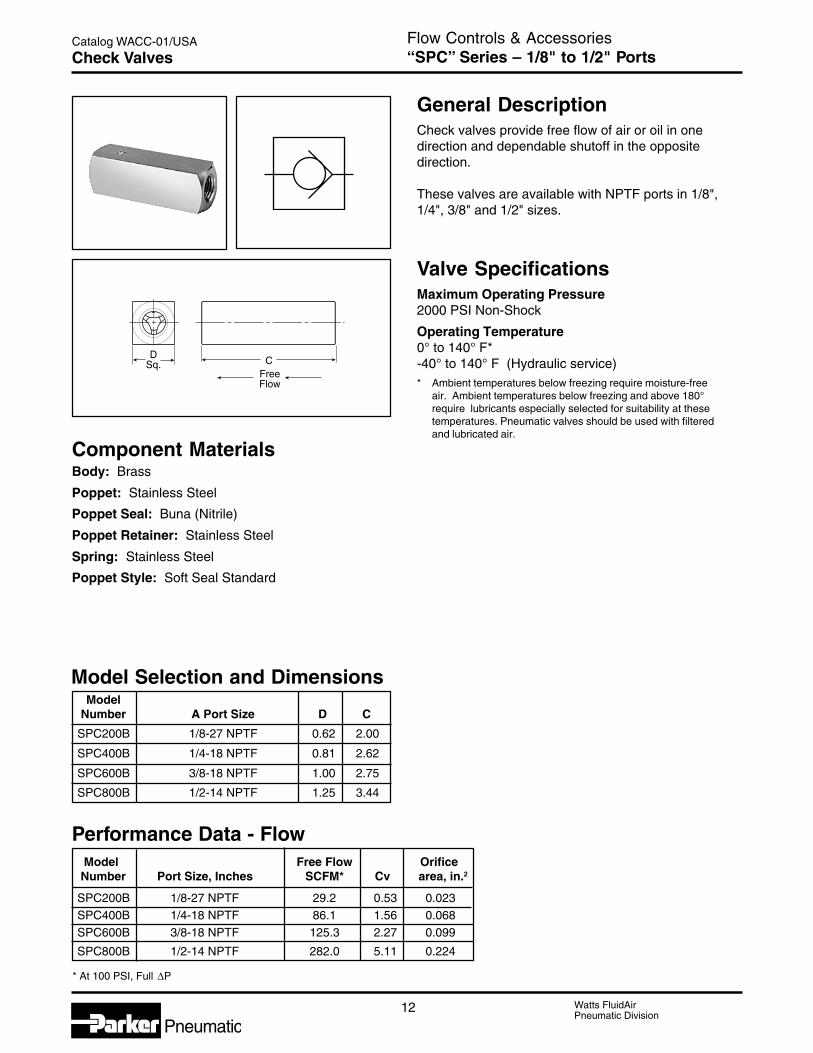
Catalog WACC-01/USA Flow Controls & Accessories“SPC” Series – 1/8" to 1/2" PortsCheck Valves
General DescriptionCheck valves provide free flow of air or oil in onedirection and dependable shutoff in the oppositedirection.
These valves are available with NPTF ports in 1/8",1/4", 3/8" and 1/2" sizes.
CFreeFlow
DSq.
Valve SpecificationsMaximum Operating Pressure2000 PSI Non-Shock
Operating Temperature0° to 140° F*-40° to 140° F (Hydraulic service)* Ambient temperatures below freezing require moisture-free
air. Ambient temperatures below freezing and above 180°require lubricants especially selected for suitability at thesetemperatures. Pneumatic valves should be used with filteredand lubricated air.
Component MaterialsBody: Brass
Poppet: Stainless Steel
Poppet Seal: Buna (Nitrile)
Poppet Retainer: Stainless Steel
Spring: Stainless Steel
Poppet Style: Soft Seal Standard
Model Selection and DimensionsModel
Number A Port Size D C
SPC200B 1/8-27 NPTF 0.62 2.00
SPC400B 1/4-18 NPTF 0.81 2.62
SPC600B 3/8-18 NPTF 1.00 2.75
SPC800B 1/2-14 NPTF 1.25 3.44
Performance Data - Flow Model Free Flow Orifice Number Port Size, Inches SCFM* Cv area, in.2
SPC200B 1/8-27 NPTF 29.2 0.53 0.023SPC400B 1/4-18 NPTF 86.1 1.56 0.068SPC600B 3/8-18 NPTF 125.3 2.27 0.099
SPC800B 1/2-14 NPTF 282.0 5.11 0.224
* At 100 PSI, Full ΔP
13 Watts FluidAirPneumatic Division
Pneumatic
Catalog WACC-01/USA
C
D
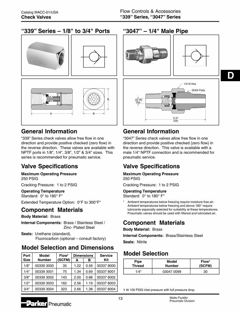
Flow Controls & Accessories“339” Series, “3047” SeriesCheck Valves
“3047” – 1/4" Male Pipe“339” Series – 1/8" to 3/4" Ports
General InformationGeneral Information“339” Series check valves allow free flow in onedirection and provide positive checked (zero flow) inthe reverse direction. These valves are available withNPTF ports in 1/8", 1/4", 3/8", 1/2" & 3/4" sizes. Thisseries is recommended for pneumatic service.
“3047” Series check valves allow free flow in onedirection and provide positive checked (zero flow) inthe reverse direction. This valve is available with amale 1/4" NPTF connection and is recommended forpneumatic service.
Valve SpecificationsMaximum Operating Pressure250 PSIG
Cracking Pressure: 1 to 2 PSIG
Operating TemperatureStandard: 0° to 180° F*
Extended Temperature Option: 0°F to 300°F*
Component MaterialsBody Material: Brass
Internal Components: Brass / Stainless Steel /Zinc- Plated Steel
Seals: Urethane (standard), Fluorocarbon (optional – consult factory)
BA
B .22 (6)Dia.
2.31(59)
13/16 Hex
35/64 Flats
Valve SpecificationsMaximum Operating Pressure250 PSIG
Cracking Pressure: 1 to 2 PSIG
Operating TemperatureStandard: 0° to 180° F** Ambient temperatures below freezing require moisture-free air.
Ambient temperatures below freezing and above 180° requirelubricants especially selected for suitability at these temperatures.Pneumatic valves should be used with filtered and lubricated air.
Component MaterialsBody Material: Brass
Internal Components: Brass/Stainless Steel
Seals: Nitrile
† At 100 PSIG inlet pressure with full pressure drop.
Model Selection and DimensionsPort Model Flow† Dimensions ServiceSize Number (SCFM) A B Kit
1/8" 00339 3000 35 1.22 0.56 00337 8000
1/4" 00339 3001 75 1.34 0.69 00337 8001
3/8" 00339 3002 143 2.00 0.88 00337 8002
1/2" 00339 3003 162 2.56 1.19 00337 8003
3/4" 00339 3004 323 2.66 1.38 00337 8004
Model SelectionPipe Model Flow†
Thread Number (SCFM)
1/4" 03047 0099 30
14 Watts FluidAirPneumatic Division
Pneumatic
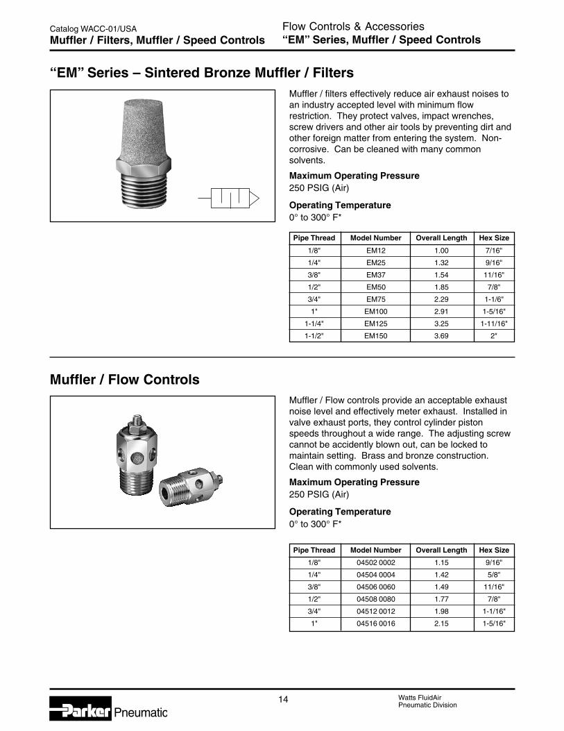
Catalog WACC-01/USA Flow Controls & Accessories“EM” Series, Muffler / Speed ControlsMuffler / Filters, Muffler / Speed Controls
Muffler / filters effectively reduce air exhaust noises toan industry accepted level with minimum flowrestriction. They protect valves, impact wrenches,screw drivers and other air tools by preventing dirt andother foreign matter from entering the system. Non-corrosive. Can be cleaned with many commonsolvents.
Maximum Operating Pressure250 PSIG (Air)
Operating Temperature0° to 300° F*
Muffler / Flow ControlsMuffler / Flow controls provide an acceptable exhaustnoise level and effectively meter exhaust. Installed invalve exhaust ports, they control cylinder pistonspeeds throughout a wide range. The adjusting screwcannot be accidently blown out, can be locked tomaintain setting. Brass and bronze construction.Clean with commonly used solvents.
Maximum Operating Pressure250 PSIG (Air)
Operating Temperature0° to 300° F*
Pipe Thread Model Number Overall Length Hex Size
1/8" EM12 1.00 7/16"
1/4" EM25 1.32 9/16"
3/8" EM37 1.54 11/16"
1/2" EM50 1.85 7/8"
3/4" EM75 2.29 1-1/6"
1" EM100 2.91 1-5/16"
1-1/4" EM125 3.25 1-11/16"
1-1/2" EM150 3.69 2"
“EM” Series – Sintered Bronze Muffler / Filters
Pipe Thread Model Number Overall Length Hex Size
1/8" 04502 0002 1.15 9/16"
1/4" 04504 0004 1.42 5/8"
3/8" 04506 0060 1.49 11/16"
1/2" 04508 0080 1.77 7/8"
3/4" 04512 0012 1.98 1-1/16"
1" 04516 0016 2.15 1-5/16"

15 Watts FluidAirPneumatic Division
Pneumatic
Catalog WACC-01/USA
C
D
Flow Controls & AccessoriesBreather Vents & “ES” SeriesBreather Vents, Silencers
Breather VentsThese low silhouette versions of the muffler/filter areuseful where space is a problem and/or to preventcontamination. Use for vacuum relief or pressureequalization in gear boxes, oil tanks, reservoirs, etc.Non-corrosive.
Maximum Operating Pressure250 PSIG (Air)
Operating Temperature0° to 300° F** Ambient temperatures below freezing require moisture-free air.
Ambient temperatures below freezing and above 180° requirelubricants especially selected for suitability at these temperatures.Pneumatic valves should be used with filtered and lubricated air.
NOTE: Breather vents should notbe used as exhaust mufflers.
“ES” Series – Silencer
AC
NPT
D
BE
Pipe Thread Model Number Overall Length Hex Size
1/8" 04702 0002 0.44 7/16"
1/4" 04704 0004 0.63 9/16"
3/8" 04706 0006 0.75 11/16"
1/2" 04708 0008 0.88 7/8"
3/4" 04712 0012 1.00 1-1/6"
1" 04716 0016 1.31 1-5/16"
1-1/4" 04720 0020 1.41 1-11/16"
1-1/2" 04724 0024 1.50 2"
Pipe ThreadModel Numbers
Flow SCFM @ 100 PSIG InletDimensions
NPTF BSPT (R) A B C D E
1/8" ES12MB ESB12MB 115 2.31 0.62 0.31 0.68 5/8"
1/4" ES25MB ESB25MB 129 2.41 0.88 0.50 0.97 7/8"
3/8" ES37MB ESB37MB 219 3.06 1.25 0.50 1.38 1-1/4"
1/2" ES50MB ESB50MB 549 3.19 1.25 0.64 1.38 1-1/4"
3/4" ES75MB ESB75MB 893 4.69 1.50 0.66 1.62 1-1/2"
1" ES100MB ESB100MB 1,013 4.69 1.50 0.81 1.62 1-1/2"
1-1/4" ES125MB ESB125MB 1,486 5.69 2.88 1.25 — —
1-1/2" ES150MB ESB150MB 1,580 5.69 2.88 1.25 — —
The silencer is designed to give superior performancein noise control with a minimum effect on air efficiency.“Trimline” design allows location in the tightest placeswithout extra plumbing and fittings. Fits directly into theexhaust port of more than 90% of present commercialvalves. Slotted body permits rapid discharge of airwithout undesirable back pressure. Unique nylonscreen element resists dirt buildup or clogging.
Maximum Operating Pressure
250 PSIG (Air)
Operating Temperature
0° to 300° F*

16 Watts FluidAirPneumatic Division
Pneumatic
Catalog WACC-01/USA
B
A
Flow Controls & AccessoriesASN Series – M5, 1/8", 1/4", 3/8" & 1/2"Air Line Silencer – Plastic
Features• Compact
• Lightweight
• Easy to install
• Excellent noise reduction
• Protects components fromcontamination
• NPT & BSPT threads available
ApplicationThe plastic silencer is designed to give excellent noisereduction with a minimum effect on air efficiency.The “Trimline” design allows for locating the silencerin the tightest places without extra plumbing or fittings.Fits directly into the exhaust port of most commercialvalves. Open surface area of element allows for rapiddischarge of air without undesirable back pressure.
Specifications
Body:Acetal (Plastic)
Element:Polyethylene
Pressure Rating:0 to 150 PSIG(0 to 10 bar, 0 to 1034 kPa)
Temperature Rating:14°F to 140°F (-10°C to 60°C)
Part Maximum Flow Sound PressureThread Number A B (SCFM) Level (dBA)
SizeNPT BSPT
(mm) (mm) 100 PSIG Inlet 20 PSIG 100 PSIGInlet Inlet
M5 AS-5 .43 .32 15 69 79(11) (8)
1/8" ASN-6 AS-6 1.57 .63 51 69 81(40) (16)
1/4" ASN-8 AS-8 2.56 .83 124 67 84(65) (21)
3/8" ASN-10 AS-10 3.35 .98 247 83 98(85) (25)
1/2" ASN-15 AS-15 3.74 1.18 370 69 96(95) (30)

17 Watts FluidAirPneumatic Division
Pneumatic
Catalog WACC-01/USA
C
D
Flow Controls & AccessoriesECS Series – 1/2" & 1"Air Line Muffler – Reclassifier
0 10 20 30 40 50 60 70 80 90 100
SCFM
0
20
40
60
80
100
120
Flow vs. Noise Level
■
❏
●
❍
■❏
●❍ 1" Open Pipe
ECS51/2" Open PipeECS3
dBa
10 20 30 40dm3/sn
0 10 20 30 40 50 60 70 80 90 100
SCFM
0
2
4
6
8
10
Flow vs. Back Pressure
■ ●
■
●
ECS3 Back PressureECS5 Back Pressure
PSID
10 20 30 40dm3/sn
.14
.28
.41
.55
.69
bar
Dimensions:Model A B CECS3 5.30 1/2" 2.57
(135 mm) NPT (65 mm)ECS5 7.30 1" 2.57
(185mm) NPT (65mm)
A
C
B
Performance Characteristics
FeaturesThe ECS (Muffler-Reclassifier) eliminates unwanted oilmist and reduces exhaust noise from pneumaticvalves, cylinders and air motors.
• 99.97% Oil removal efficiencies
• 25 dBA Noise attenuation
• 1/2" NPT and 1" NPT
• Disposable units
• Continuous or plugged drain option
• Metal retained construction
• Fast exhaust time
Improve Overall Plant EnvironmentExhaust oil mist and noise pollution have a directimpact on worker productivity.
Oil aerosol mist from lubricators and compressors ispervasive and enters the industrial plant environmentthrough the exhaust ports of valves, cylinders and airmotors. This rapidly expanding exhaust also producessudden and excessive noise.
The ECS (Muffler-Reclassifier) is 99.97% efficient atremoving the oil aerosols. The ECS also acts as asilencer to lower the dBA levels below O.S.H.A.requirements.
The result is a cleaner, quieter environment whichequates to greater work productivity and safety.
OperationCompressor oils and lubricating oils are exhaustedfrom valves, cylinders and air motors into the ECS.Oil aerosols are “coalesced” into larger droplets andgravity pulls them into the attached drain sump.The sump can then be drained manually or by usinga 1/4" ID plastic tube drain. The air flowing into theECS is also muffled or silenced as it enters the insideof the ECS and passes through the filter media intothe atmosphere.
Proven TechnologyThe ECS units are constructed from the samematerials that go into our oil removal coalescing filterelements.The seamless design insures media uniformity andstrength. This proven technology provides highcoalescing efficiency with low pressure drop.
The filter media is supported by cylindrical perforatedsteel retainers both inside and out. These retainers,fully plated for excellent corrosion resistance, give theECS units high rupture strength in either flow direction.These filters can also be used as high efficiency inlet orbypass filters for vacuum pumps, or breather elementsto protect the air above critical process liquids.
ECS3 / ECS5The ECS solves two problems inherent in compressedair exhaust from valves, cylinders and air motors - oilmist removal and noise abatement.
The ECS will improve your industrial plant environment,thereby improving worker productivity.
SpecificationsMaximum Operating Temperature125°F (52°C)
Maximum Line Pressure100 PSIG (690 kPa)
Ordering Information
ECS 3 A
EngineeringSize Level
A. Current3. 1/2 inch5. 1 Inch
18 Watts FluidAirPneumatic Division
Pneumatic
Catalog WACC-01/USA Flow Controls & AccessoriesFeatures & OperationAutomatic Drip Leg Drain, Relief Valve
F
C
BA
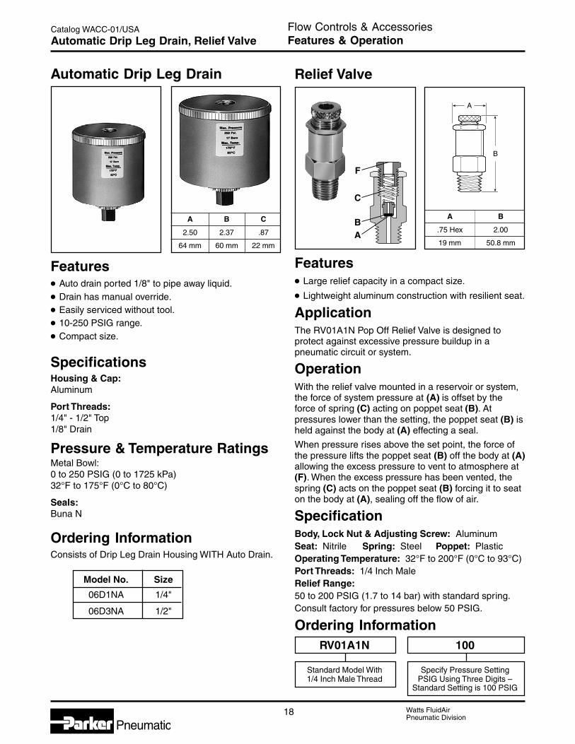
Relief ValveAutomatic Drip Leg Drain
A B
.75 Hex 2.00
19 mm 50.8 mm
A
B
Features• Large relief capacity in a compact size.
• Lightweight aluminum construction with resilient seat.
ApplicationThe RV01A1N Pop Off Relief Valve is designed toprotect against excessive pressure buildup in apneumatic circuit or system.
OperationWith the relief valve mounted in a reservoir or system,the force of system pressure at (A) is offset by theforce of spring (C) acting on poppet seat (B). Atpressures lower than the setting, the poppet seat (B) isheld against the body at (A) effecting a seal.
When pressure rises above the set point, the force ofthe pressure lifts the poppet seat (B) off the body at (A)allowing the excess pressure to vent to atmosphere at(F). When the excess pressure has been vented, thespring (C) acts on the poppet seat (B) forcing it to seaton the body at (A), sealing off the flow of air.
SpecificationBody, Lock Nut & Adjusting Screw: AluminumSeat: Nitrile Spring: Steel Poppet: PlasticOperating Temperature: 32°F to 200°F (0°C to 93°C)Port Threads: 1/4 Inch MaleRelief Range:50 to 200 PSIG (1.7 to 14 bar) with standard spring.Consult factory for pressures below 50 PSIG.
Ordering Information
Features• Auto drain ported 1/8" to pipe away liquid.
• Drain has manual override.
• Easily serviced without tool.
• 10-250 PSIG range.
• Compact size.
SpecificationsHousing & Cap:Aluminum
Port Threads:1/4" - 1/2" Top1/8" Drain
Pressure & Temperature RatingsMetal Bowl:0 to 250 PSIG (0 to 1725 kPa)32°F to 175°F (0°C to 80°C)
Seals:Buna N
Ordering InformationConsists of Drip Leg Drain Housing WITH Auto Drain.
Model No. Size
06D1NA 1/4"
06D3NA 1/2"
A B C
2.50 2.37 .87
64 mm 60 mm 22 mm
RV01A1N 100
Standard Model With Specify Pressure Setting1/4 Inch Male Thread PSIG Using Three Digits –
Standard Setting is 100 PSIG

19 Watts FluidAirPneumatic Division
Pneumatic
Catalog WACC-01/USA
C
D
Flow Controls & Accessories“0R” Series – 1/8" thru 3/4" PortsQuick Exhaust & Shuttle Valves
1
3
2
C
A
B
Port 1 (In)
Port 3 (Exh) Port 2 (Cyl)
† At 100 PSIG inlet pressure with full pressure drop.
General InformationQuick exhaust valves provide rapid exhaust of controlair when placed between control valve and actuator.They can also be used as shuttle valves.Diaphragm materials are available in urethane, Nitrile,Fluorocarbon, and PTFE to meet a wide variety ofoperating conditions.
Valve SpecificationsOperating Pressure (Air)Maximum: 150 PSIG
200 PSIG for Model No. 03340 0199(PTFE diaphragm)
Minimum: 3 PSIG50 PSIG for Model No. 03340 0199(PTFE diaphragm)
Operating TemperatureUrethane: 0°F to 180°F* (-18°C to 80°C)Nitrile: 0°F to 180°F* (-18°C to 80°C)Fluorocarbon: 0°F to 400°F* (-18°C to 205°C)PTFE: 0°F to 500°F* (-18°C to 260°C)* Ambient temperatures below freezing require moisture-free air.
Ambient temperatures below freezing and above 180° requireslubricants especially selected for suitability at these temperatures.Pneumatic valves should be used with filtered and lubricated air.
Component MaterialsBody Material: Die cast aluminumStatic Seals: Nitrile standard with urethane
(Others see below)Diaphragm: Standard – Urethane
Optional – Fluorocarbon, PTFE,or Nitrile (Depending on size)
Mounting Bracket Kit –No. 03640 8100(Including body screws)For “0R12” and “0R25” sizes.
† At 100 PSIG inlet pressure with full pressure drop. Bold part numbers standard.
Model Selection, Performance Data and DimensionsPort Flow Model Number Service
1 2 3 (SCFM†) NPTF BSPP “G”A B C
Kit No.
STANDARD URETHANE DIAPHRAGMS (Nitrile static seals)
1/8"1/8" 1/8" 70 0R12B 0RB12B 7/8" Sq. 1.75 1.88 03640 8000
1/8" 1/4" 70 0R12NB 0RB12NB 7/8" Sq. 1.75 1.88 03640 8000
1/4" 1/4" 90 0R25B 0RB25B 7/8" Sq. 1.75 1.88 03640 80001/4" 1/4" 3/8" 150 0R25NB 0RB25NB 1" Hex 2.06 2.44 03340 0105
3/8" 3/8" 240 0R25PB 0RB25PB 1" Hex 2.06 2.44 03340 0105
3/8" 3/8" 3/8" 240 0R37B 0RB37B 1" Hex 2.06 2.44 03340 0105
1/2" 1/2" 1/2" 450 0R50B 0RB50B 1-1/2" Hex 2.88 3.38 03475 01093/4" 3/4" 3/4" 550 0R75B 0RB75B 1-1/2" Hex 2.88 3.38 03475 0109
NITRILE DIAPHRAGMS (Nitrile static seals)
1/4"1/4" 3/8" 90 0R25NFB 0RB25NFB 7/8" Sq. 1.75 1.88 03340 8000
3/8" 3/8" 150 0R25PFB 0RB25PFB 1" Hex 2.06 2.44 03340 80003/8" 3/8" 3/8" 240 0R37FB 0RB37FB 1" Hex 2.06 2.44 03340 8000
3/4" 3/4" 3/4" 550 0R75FB 0RB75FB 1-1/2" Hex 2.88 3.38 03475 9000
FLUOROCARBON DIAPHRAGMS for extended temperature operation (Fluorocarbon static seals)
1/8"1/8" 1/8" 70 0R12VB 0RB12VB 7/8" Sq. 1.75 1.88 03650 80001/8" 1/4" 70 0R12NVB 0RB12NVB 7/8" Sq. 1.75 1.88 03650 8000
1/4" 1/4" 1/4" 90 0R25VB 0RB25VB 7/8" Sq. 1.75 1.88 03650 8000
3/8" 3/8" 3/8" 240 0R37VB 0RB37VB 1" Hex 2.06 2.44 03340 0319
1/2" 1/2" 1/2" 450 0R50VB 0RB50VB 1-1/2" Hex 2.88 3.38 03475 01203/4" 3/4" 3/4" 550 0R75VB 0RB75VB 1-1/2" Hex 2.88 3.38 03475 0120
PTFE DIAPHRAGMS for higher pressure and temperature (Fibre static seals)3/8" 3/8" 3/8" 240 0R37TB 0RB37TB 1" Hex 2.06 2.44 03340 0504
12
3
20 Watts FluidAirPneumatic Division
Pneumatic
Catalog WACC-01/USA
Pressure
Pressure
Pressure
Man
Reg
Pressure
Pressure
Operation 1
Operation 2
Op
erat
ion
3
Operation
A B
B
BC
A
Man
AMan
CMan
D
MAN
Man
Pressure
Man
Man
Flow Controls & AccessoriesTypical ApplicationsQuick Exhaust & Shuttle Valve
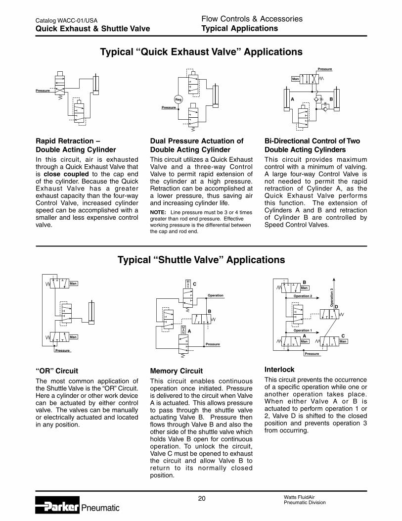
Rapid Retraction –Double Acting CylinderIn this circuit, air is exhaustedthrough a Quick Exhaust Valve thatis close coupled to the cap endof the cylinder. Because the QuickExhaust Valve has a greaterexhaust capacity than the four-wayControl Valve, increased cylinderspeed can be accomplished with asmaller and less expensive controlvalve.
Dual Pressure Actuation ofDouble Acting CylinderThis circuit utilizes a Quick ExhaustValve and a three-way ControlValve to permit rapid extension ofthe cylinder at a high pressure.Retraction can be accomplished ata lower pressure, thus saving airand increasing cylinder life.NOTE: Line pressure must be 3 or 4 timesgreater than rod end pressure. Effectiveworking pressure is the differential betweenthe cap and rod end.
Bi-Directional Control of TwoDouble Acting CylindersThis circuit provides maximumcontrol with a minimum of valving.A large four-way Control Valve isnot needed to permit the rapidretraction of Cylinder A, as theQuick Exhaust Valve performsthis function. The extension ofCylinders A and B and retractionof Cylinder B are controlled bySpeed Control Valves.
Typical “Shuttle Valve” Applications
Typical “Quick Exhaust Valve” Applications
“OR” CircuitThe most common application ofthe Shuttle Valve is the “OR” Circuit.Here a cylinder or other work devicecan be actuated by either controlvalve. The valves can be manuallyor electrically actuated and locatedin any position.
Memory CircuitThis circuit enables continuousoperation once initiated. Pressureis delivered to the circuit when ValveA is actuated. This allows pressureto pass through the shuttle valveactuating Valve B. Pressure thenflows through Valve B and also theother side of the shuttle valve whichholds Valve B open for continuousoperation. To unlock the circuit,Valve C must be opened to exhaustthe circuit and allow Valve B toreturn to its normally closedposition.
InterlockThis circuit prevents the occurrenceof a specific operation while one oranother operation takes place.When either Valve A or B isactuated to perform operation 1 or2, Valve D is shifted to the closedposition and prevents operation 3from occurring.

21 Watts FluidAirPneumatic Division
Pneumatic
Catalog WACC-01/USA
C
D
Flow Controls & Accessories1/8" to 3/8" PortsShuttle Valve
C
F
E
G B
AA1
J
H
K(3 Ports)
L Dia.(2 Holes)
OUTLET
INLETINLET
D
Shuttle valves determine a single pneumatic outputfrom two separate inputs. If pressure is applied toboth ports simultaneously, the valve will select theport with the higher pressure.
Component MaterialsBody Material: Aluminum
Internal Components: Aluminum
Seals: Nitrile
General Information
Valve SpecificationsMaximum Operating Pressure200 PSIG Maximum
3 PSIG Minimum: Differential Pressure
Operating Temperature0° to160° F*
* Ambient temperatures below freezing require moisture-free air.Ambient temperatures below freezing and above 180° requirelubricants especially selected for suitability at these temperatures.Pneumatic valves should be used with filtered and lubricated air.
12
3
Model Selection and Dimensions
Performance Data – Flow
Port DimensionsSize Model A A1 B C D E F G H J K L
1/8" N164 1001 N/A 1.62 0.81 0.62 0.31 1.00 .281 0.312 1.00 0.75 1/8 - 27 0.219
1/4" N164 2003 2.50 2.12 1.25 1.25 0.62 2.00 0.67 0.265 1.25 1.35 1/4 - 18 0.219
3/8" N164 3003 2.50 2.12 1.25 1.25 0.62 2.00 0.67 0.265 1.25 1.35 3/8 - 16 0.219
Port Model FlowSize Number (Cv)
1/8" N164 1001 0.32
1/4" N164 2003 1.65
3/8" N164 3003 2.02
(Revised 8/18/05)

22 Watts FluidAirPneumatic Division
Pneumatic
Catalog WACC-01/USA Flow Controls & AccessoriesNotes

Watts FluidAirPneumatic Division
Pneumatic
E
Fittings & Hose
Section E
Pneumatic
Application Guide & Hose Reel Footage .................... 2Push-on Hose Fittings
Basic Features ..................................................... 3Part Numbers & Dimensions ............................. 4-6
Push-on Hose............................................................. 7General Purpose Hose ............................................... 8Selection Guide ..................................................... 9-10Chemical Compatibility Guide (GPH) .................. 11-12

Watts FluidAirPneumatic Division
Pneumatic2
Catalog WACC-01/USA
Series of Hose
Media (4, 5, 6) Push-on General Purpose
831 GPH(Black Cover) (Gray & Colors)
Air & Inert Gas • (1) • (1)
Ethanol •Ethylene Glycol • (2) • (1)
Lubricating Oils • •(Petroleum Base)Methanol •Water • (2) • (1)
Water Glycol • (2) • (1)
Vacuum • (3) •Other
Push-on GPHCharacteristicsAbrasion Resistant •Oil Resistant • •Ozone Resistant • •Ultra Violet Resistant • •Weather Resistant •Notes:
(1) 150°F Maximum Temperature
(2) 180°F Maximum Temperature
(3) Limited by Hose I.D.
(4) ! CAUTION: Do not use Synthetic Rubber Hose or PVC Hose if some media permeation (see page 9 & 10)is not acceptable or if such permeation cause a hazard.
(5) Consult the supplier for approval of medium not shown.
(6) See Guide For Selecting and Using Hose (Tubing) & Fittings on page 9 & 10.
Synthetic Rubber Hose Reel Footage
Approx. Reel SizeMaximum Minimum Feet
Hose Type I.D.(Feet)
Number of of HoseLengths on Reel in Each Length
Push-on 831 1/4" 500 ± 50 4 10
Push-on 831 3/8" 350 ± 35 4 10
Push-on 831 1/2" 220 ± 22 3 10
Push-on 831 5/8" 200 ± 20 3 10
Push-on 831 3/4" 145 ± 15 3 10
Standard Duty 1/4" & 3/8" 500 ± 100 3 100
Standard Duty 1/2" 500 ± 100 2 100
Fittings & HoseApplication Guide & Hose Reel FootageTechnical Information
Fitting & Hose Application Guide
3 Watts FluidAirPneumatic Division
Pneumatic
Catalog WACC-01/USA
E
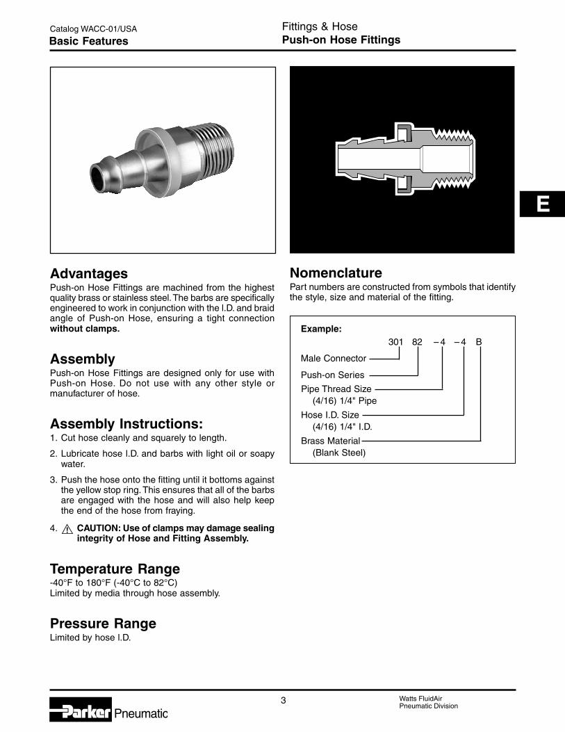
AdvantagesPush-on Hose Fittings are machined from the highestquality brass or stainless steel. The barbs are specificallyengineered to work in conjunction with the l.D. and braidangle of Push-on Hose, ensuring a tight connectionwithout clamps.
AssemblyPush-on Hose Fittings are designed only for use withPush-on Hose. Do not use with any other style ormanufacturer of hose.
Assembly Instructions:1. Cut hose cleanly and squarely to length.
2. Lubricate hose l.D. and barbs with light oil or soapywater.
3. Push the hose onto the fitting until it bottoms againstthe yellow stop ring. This ensures that all of the barbsare engaged with the hose and will also help keepthe end of the hose from fraying.
4. ! CAUTION: Use of clamps may damage sealingintegrity of Hose and Fitting Assembly.
Temperature Range-40°F to 180°F (-40°C to 82°C)Limited by media through hose assembly.
Pressure RangeLimited by hose l.D.
NomenclaturePart numbers are constructed from symbols that identifythe style, size and material of the fitting.
Example:301 82 – 4 – 4 B
Male Connector
Push-on Series
Pipe Thread Size(4/16) 1/4" Pipe
Hose I.D. Size(4/16) 1/4" I.D.
Brass Material(Blank Steel)
Fittings & HosePush-on Hose FittingsBasic Features

Watts FluidAirPneumatic Division
Pneumatic4
Catalog WACC-01/USA
30182 Push-on Hose Barb to Male Pipe
HosePart Thread Size A H BNo. Inch Inch Inch mm Inch mm Inch mm30182-2-4B 1/8 x 27 -2 1/4 -4 1.39 35 7/16 0.63 .64 16
30182-4-4B 1/4 x 18 -4 1/4 -4 1.57 40 9/16 0.82 .82 2130182-4-6B 1/4 x 18 -4 1/4 -4 1.78 45 9/16 0.82 .88 2230182-6-6B 3/8 x 18 -6 3/8 -6 1.78 45 11/16 0.88 .88 22
30182-8-6B 1/2 x 14 -8 3/8 -6 2.03 52 7/8 1.13 1.13 2930182-6-8B 3/8 x 18 -6 1/2 -8 1.93 49 11/16 0.88 .88 2230182-8-8B 1/2 x 14 -8 1/2 -8 2.18 55 7/8 1.13 1.13 29
30182-12-8B 3/4 x 14 -12 1/2 -8 2.21 56 1-1/16 1.16 1.16 2930182-8-10B 1/2 x 14 -8 5/8 -10 2.58 66 7/8 1.13 1.13 2930182-12-12B 3/4 x 14 -12 3/4 -12 2.61 66 1-1/16 1.16 1.16 29
30282 Push-on Hose Barb to Female Pipe
HosePart Thread Size A H BNo. Inch Inch Inch mm Inch Inch mm30282-4-4B 1/4 x 18 -4 1/4 -4 1.56 40 3/4 .81 2130282-6-6B 3/8 x 18 -6 3/8 -6 1.82 46 7/8 .92 2330282-8-8B 1/2 x 14 -8 1/2 -8 2.16 55 1-1/16 1.11 28
30482 Push-on Hose Barb to Male SAE 45°
HosePart Thread Size A H BNo. Inch Inch Inch mm Inch Inch mm30482-4-4B 1/4 7/16 x 20 -4 1/4 -4 1.51 38 7/16 0.76 1930482-5-4B 5/16 1/2 x 20 -5 1/4 -4 1.61 41 9/16 0.86 22
30482-6-6B 3/8 5/8 x 18 -6 3/8 -6 1.84 47 5/8 0.94 2430482-8-8B 1/2 3/4 x 16 -8 1/2 -8 2.15 55 3/4 1.1 28
BA
H
BA
H
BA
H
Fittings & HosePush-on Hose FittingsPart Numbers & Dimensions
#
#
#

5 Watts FluidAirPneumatic Division
Pneumatic
Catalog WACC-01/USA
E
30682 Push-on Hose Barb to Female SAE JIC 37° Swivel
HosePart Thread Size A H BNo. Inch Inch Inch mm Inch Inch mm30682-4-4B 1/4 7/16 x 20 -4 1/4 -4 1.52 39 9/16 0.77 2030682-5-4B 5/16 1/2 x 12 -5 1/4 -4 1.58 40 5/8 0.83 2130682-6-6B 3/8 9/16 x 18 -6 1/4 -4 1.61 41 11-16 0.86 22
30682-8-6B 1/2 3/4 x 16 -8 3/8 -6 1.87 47 7/8 0.97 2530682-8-8B 1/2 3/4 x 16 -8 1/2 -8 2.02 51 7/8 0.97 2530682-10-8B 5/8 7/8 x 14 -10 1/2 -8 2.14 54 1 1.09 28
30682-10-10B 5/8 7/8 x 14 -10 5/8 -10 2.54 65 1 1.09 2830682-12-12B 3/4 1-1/16 x 12 -12 3/4 -12 2.65 67 1-1/4 1.2 30
30882 Push-on Hose Barb to Female SAE 45° Swivel
HosePart Thread Size A H BNo. Inch Inch Inch mm Inch Inch mm30882-4-4B 1/4 7/16 x 20 -4 1/4 -4 1.52 39 9/16 0.76 19
30882-5-4B 5/16 1/2 x 20 -5 1/4 -4 1.58 40 5/8 0.83 2130882-6-6B 3/8 5/8 x 18 -6 3/8 -6 1.81 46 3/4 0.91 2330882-8-6B 1/2 3/4 x 16 -8 3/8 -6 1.87 47 7/8 0.97 25
30882-8-8B 1/2 3/4 x 16 -8 1/2 -8 2.02 51 7/8 0.97 2530882-10-8B 5/8 7/8 x 14 -10 1/2 -8 2.14 54 1 1.09 2830882-10-10B 5/8 7/8 x 14 -10 5/8 -10 2.54 65 1 1.09 28
30882-12-12B 3/4 1-1/16 x 14 -12 3/4 -12 2.65 67 1-1/4 1.19 30
31382 Push-on Hose Barb to Male Pipe Swivel
HosePart Thread Size A W BNo. Inch Inch Inch mm Inch Inch mm31382-4-4 1/4 x 18 -4 1/4 -4 1.6 41 9/16 .85 2231382-6-6 3/8 x 18 -6 3/8 -6 1.79 45 11/16 .89 23
31382-8-8* 1/2 x 14 -8 1/2 -8 2.2 56 7/8 1.15 29* Steel
BA
W
BA
H
B
A
H
Fittings & HosePush-on Hose FittingsPart Numbers & Dimensions
#
#
#

Watts FluidAirPneumatic Division
Pneumatic6
Catalog WACC-01/USA
37G82 Push-on Hose Barb to Female Pipe (NPSM)Swivel with Gasket
HosePart Thread Size A W BNo. Gasket Inch Inch Inch mm Inch Inch mm37G82-4-4 07G-4 1/4- 18 -4 1/4 -4 1.55 39 11/16 0.80 2037G82-4-6 07G-4 1/4- 18 -4 3/8 -6 1.7 43 11/16 0.80 20
37G82-6-6 07G-6 3/8- 18 -6 3/8 -6 1.75 44 7/8 0.85 2237G82-8-8 07G-8 1/2- 14 -8 1/2 -8 2.07 53 1 1.02 2637G82-8-10 07G-8 1/2- 14 -8 5/8 -10 2.47 63 1 1.02 26
37G82-12-12 07G-12 3/4- 14 -12 3/4 -12 2.54 65 1-1/4 1.09 28
38282 Push-on Hose Barb Union
HosePart Size ANo. Inch Inch mm38282-4-4B 1/4 -4 1.80 4638282-6-6B 3/8 -6 2.15 5538282-8-8 1/2 -8 2.51 64
BA
W
A
Fittings & HosePush-on Hose FittingsPart Numbers & Dimensions
#
#

7 Watts FluidAirPneumatic Division
Pneumatic
Catalog WACC-01/USA
E
ConstructionSynthetic rubber core tube, one textile braidreinforcement, MSHA accepted synthetic rubber cover.
Application andTemperature RangeWidely used for shop air systems and generalindustrial, maintenance and automotive applications.
Petroleum based hydraulic fluids and lubricating oils,and antifreeze solutions within a temperature range of-40°F to +212°F (-40°C to +100°C).
Water, water / oil emulsion, and water / glycolhydraulic fluids up to +185°F (+85°C).
Air within a temperature range of -40°F to +158°F
(-40°C to +70°C).
Push-on Hose 831
Working Burst Minimum VacuumHose I.D. Hose O.D. Pressure Pressure Bend Radius Weight Rating
InchesPart No. Inch mm Inch mm PSI MPa PSI MPa Inch mm lbs/ft kg/m of Hg kPa831-4 1/4 6,3 0.50 12,7 350 2,4 1400 9,7 2-1/2 65 0.09 0,13 28 95831-6 3/8 10 0.62 16 300 2,0 1200 8,3 3 75 0.11 0,16 28 95831-8 1/2 12,5 0.75 20 300 2,0 1200 8,3 5 125 0.18 0,27 28 95
831-10 5/8 16 0.91 23 300 2,0 1200 8,3 6 150 0.19 0,28 15 51831-12 3/4 19 1.03 26 300 2,0 1200 8,3 7 180 0.24 0,36 15 51
Fittings & HosePush-on HoseFeatures & Part Numbers
Example:831 – 4
831 Series
Size 1/4" I.D. (4/16)
Water ServiceUp to 180°F (82°C).
Fitting RecommendationsUse only with Push-on Hose Fittings and QuickCouplers with Push-lock Hose Barb.
NomenclaturePart numbers are constructed from symbols that identifyhe style and size of the hose. Numbers identify the hosel.D. in 1/16’s of an inch.
# kgHg
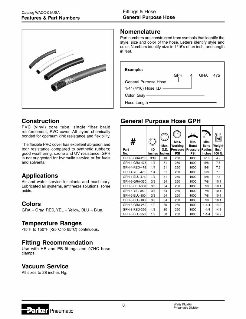
Watts FluidAirPneumatic Division
Pneumatic8
Catalog WACC-01/USA
ConstructionPVC (vinyl) core tube, single fiber braidreinforcement, PVC cover. All layers chemicallybonded for optimum kink resistance and flexibility.
The flexible PVC cover has excellent abrasion andtear resistance compared to synthetic rubbers;good weathering, ozone and UV resistance. GPHis not suggested for hydraulic service or for fuelsand solvents.
ApplicationsAir and water service for plants and machinery.Lubricated air systems, antifreeze solutions, someacids.
ColorsGRA = Gray, RED, YEL = Yellow, BLU = Blue.
Temperature Ranges-15°F to 150°F (-25°C to 65°C) continuous.
Fitting RecommendationUse with HB and PB fittings and 97HC hoseclamps.
Vacuum ServiceAll sizes to 28 inches Hg.
NomenclaturePart numbers are constructed from symbols that identify thestyle, size and color of the hose. Letters identify style andcolor. Numbers identify size in 1/16’s of an inch, and lengthin feet.
Example:GPH 4 GRA 475
General Purpose Hose
1/4" (4/16) Hose I.D.
Color, Gray
Hose Length
General Purpose Hose GPH
Max. Min. Min.Max. Working Burst Bend Weight
Part I.D. O.D. Pressure Pressure Radius lbs./No. Inches Inches PSI PSI Inches 100 ft.GPH-3-GRA-250 3/16 .40 250 1000 7/16 4.9
GPH-4-GRA-475 1/4 .51 250 1000 5/8 7.6GPH-4-RED-475 1/4 .51 250 1000 5/8 7.6GPH-4-YEL-475 1/4 .51 250 1000 5/8 7.6
GPH-4-BLU-475 1/4 .51 250 1000 5/8 7.6GPH-6-GRA-350 3/8 .64 250 1000 7/8 10.1GPH-6-RED-350 3/8 .64 250 1000 7/8 10.1
GPH-6-YEL-350 3/8 .64 250 1000 7/8 10.1GPH-6-BLU-350 3/8 .64 250 1000 7/8 10.1GPH-6-BLU-100 3/8 .64 250 1000 7/8 10.1
GPH-8-GRA-250 1/2 .80 250 1000 1-1/4 14.2GPH-8-RED-250 1/2 .80 250 1000 1-1/4 14.2GPH-8-BLU-250 1/2 .80 250 1000 1-1/4 14.2
Fittings & HoseGeneral Purpose HoseFeatures & Part Numbers
kg
#

9 Watts FluidAirPneumatic Division
Pneumatic
Catalog WACC-01/USA
E1.0 GENERAL INSTRUCTIONS
1.1 Scope: This guide provides instructions for selecting and using(including assembling, installing, and maintaining) hose (includingall rubber and/or plastic products commonly called “hose” or“tubing”), fittings (including all products commonly called “fittings”or “couplings” for attachment to hose), and related accessories(including crimping and swaging machines and tooling). This guideis a supplement to and is to be used with, the specific publicationsfor the specific hose, fittings and related accessories that are beingconsidered for use.
1.2 Fail-Safe: Hose and hose assemblies can and do fail withoutwarning for many reasons. Design all systems and equipment in afail-safe mode, so that failure of the hose or hose assembly will notendanger persons or property.
1.3 Distribution: Provide a copy of this guide to each person that isresponsible for selecting or using hose and fitting products. Do notselect or use hose and fittings without thoroughly reading andunderstanding this guide as well as the specific publications for theproducts considered or selected.
1.4 User Responsibility: Due to the wide variety of operatingconditions and uses for hose and fittings, the manufacturer and itsdistributors do not represent or warrant that any particular hose orfitting is suitable for any specific and use system. This guide doesnot analyze all technical parameters that must be considered inselecting a product. The user, through their own analysis andtesting, are solely responsible for:• Making the final selection of the hose and fitting.• Assuring that the user’s requirements are met and that
the use presents no health or safety hazards.• Providing all appropriate health and safety warnings on
the equipment on which the hose and fittings are used.
1.5 Additional Questions: Consult the supplier if you have anyadditional questions or require additional information.
2.0 HOSE AND FITTING SELECTION INSTRUCTIONS
2.1 Electrical Conductivity: Certain applications require that a hosebe nonconductive to prevent electrical current flow. Otherapplications require the hose to be sufficiently conductive to drainoff static electricity. Extreme care must be exercised whenselecting hose and fittings for these or any other applications inwhich electrical conductivity or nonconductivity is a factor.
For applications that require hose to be electrically nonconductive,including but not limited to applications near high voltage electriclines, only special nonconductive hose can be used. Themanufacturer of the equipment in which the nonconductive hose isto be used must be consulted to be certain that the hose andfittings that are selected are proper for the application. Do not useany hose or fitting for any such application requiring nonconductivehose, including but not limited to applications near high voltageelectric lines, unless (I) the application is expressly approved in thetechnical publication for the product, (II) the hose is both orangecolor and marked “nonconductive”, and (III) the manufacturer of theequipment on which the hose is to be used specifically approvesthe particular hose and fitting for such use.
The manufacturer does not supply any hose or fittings forconveying paint in airless paint spraying or similar applications, andhose and fittings must not be so used. A special hose and fittingassembly is required for this application, to avoid static electricitybuildup. If the proper hose and fitting assembly is not used for thisapplication, static electricity can build up and cause a spark thatmay result in an explosion and/or fire.
The electrical conductivity or nonconductivity of hose and fittings isdependent upon many factors and may be susceptible to change.These factors include but are not limited to the various materialsused to make the hose and the fittings, manufacturing methods(including moisture control), how the fittings contact the hose, ageand amount of deterioration or damage or other changes, moisturecontent of the hose at any particular time, and other factors.
2.2 Pressure: Hose selection must be made so that the publishedmaximum recommended working pressure of the hose is equal toor greater than the maximum system pressure. Surge pressures inthe system higher than the published maximum recommendedworking pressure will cause failure or shorten hose life. Do notconfuse burst pressure or other pressure values with workingpressure and do not use burst pressure or other pressure valuesfor this purpose.
2.3 Suction: Hoses used for suction applications must be selected toensure that the hose will withstand the vacuum and pressure of thesystem. Improperly selected hose may collapse in suctionapplication.
2.4 Temperature: Be certain that fluid and ambient temperatures, bothsteady and transient, do not exceed the limitations of the hose.Care must be taken when routing hose near hot objects such asmanifolds.
2.5 Fluid Compatibility: Hose selection must assure compatibility ofthe hose tube, cover, reinforcement, and fittings with the fluidmedia used. See the fluid compatibility chart in the publication forthe product being considered or used.
2.6 Permeation: Permeation (that is, seepage through the hose) willoccur from inside the hose to outside when hose is used withgases, liquid and gas fuels, and refrigerants (including but notlimited to such materials as helium, fuel, oil, natural gas, or freon).This permeation may result in high concentrations of vapors whichare potentially flammable, explosive, or toxic, and in loss of fluid.Dangerous explosions, fires, and other hazards can result whenusing the wrong hose for such applications. The system designermust take into account the fact that this permeation will take placeand must not use hose if this permeation could be hazardous. Thesystem designer must take into account all legal, government,insurance, or any other special regulations which govern the use offuels and refrigerants. Never use a hose even though the fluidcompatibility is acceptable without considering the potentialhazardous effects that can result from permeation through thehose assembly.
Permeation of moisture from outside the hose to inside the hosewill also occur in hose assemblies, regardless of internal pressure.If this moisture permeation would have detrimental effects(particularly but not limited to refrigeration and air conditioningsystems), incorporation of sufficient drying capacity in the systemor other appropriate system safeguards should be selected andused.
! DANGER: Failure or improper selection or improper use of hose, fittings, or related accessories can cause death, personal injury and propertydamage.Possible consequences of failure or improper selection or improper use of hose, fittings or related accessories include but are not limited to:
• Fittings thrown off at high speed. • Dangerously whipping hose.• High velocity fluid discharge. • Contact with conveyed fluids that may be hot, cold, toxic• Explosion or burning of the conveyed fluid. or otherwise injurious.• Electrocution from high voltage electric power lines or other • Sparking or explosion caused by static electricity buildup.
sources of electricity. • Sparking or explosion while paint or flammable liquid• Contact with suddenly moving or falling objects that are to spraying.
be held in position or moved by the conveyed fluid.
Before selecting or using any hose or fittings or related accessories, it is important that you read and follow the instructions in the Guide below.
Fittings & HoseHose, Fittings & Related AccessoriesSelection Guide
Watts FluidAirPneumatic Division
Pneumatic10
Catalog WACC-01/USA Fittings & HoseHose, Fittings & Related AccessoriesSelection Guide
2.7 Size: Transmission of power by means of pressurized fluid varieswith pressure and rate of flow. The size of the components mustbe adequate to keep pressure losses to a minimum and avoiddamage due to heat generation or excessive fluid velocity.
2.8 Routing: Attention must be given to optimum routing to minimizeinherent problems (kinking or flow restriction due to hosecollapse). Freon® is a registered trademark of the E.l. DuPont DeNemours Co., Inc.
2.9 Environment: Care must be taken to ensure that the hose andfittings are either compatible with or protected from theenvironment (that is, surrounding conditions) to which they areexposed. Environmental conditions include but are not limited tooultraviolet radiation, sunlight, heat, ozone, moisture, water, saltwater, chemicals, and air pollutants that can cause degradationand premature failure.
2.10 Mechanical Loads: External forces can significantly reducehose life or cause failure. Mechanical loads which must beconsidered include excessive flexing, twist, kinking, tensile orside loads, bend radius, and vibration. Use of swivel type fittingsor adapters may be required to ensure no twist is put into thehose. Applications must be tested prior to hose selection.
2.11 Physical Damage: Care must be taken to protect hose from wear,snagging and cutting, which can cause premature hose failure.
2.13 Length: When establishing a proper hose length, motionabsorption, hose length changes due to pressure, and hose andmachine tolerances must be considered.
2.14 Specifications and Standards: When selecting hose and fittings,government, industry, and manufacturer specifications andrecommendations must be reviewed and followed as applicable.
2.15 Hose Cleanliness: Hose components may vary in cleanlinesslevels. Care must be taken to ensure that the assembly selectedhas an adequate level of cleanliness for the application.
2.16 Fire Resistant Fluids: Some fire resistant fluids require thesame hose as petroleum oil. Some use a special hose, while afew fluids will not work with any hose at all. See instructions 2.5and 1.5. The wrong hose may fail after a very short service. Inaddition, all liquids may burn fiercely under certain conditions,and leakage may be hazardous.
2.17 Radiant Heat: Hose can be heated to destruction withoutcontact, by such nearby items as hot manifolds or molten metal.The same heat source may then initiate a fire. This can occurdespite the presence of cool air around the hose.
2.18 Welding and Brazing: Heating of plated parts, including hosefittings and adapters, above 450°F (232°C) such as duringwelding, brazing, or soldering may emit deadly gases.
2.19 Radiation: Radiation affects all materials used in hoseassemblies. Since the long term effects may be unknown, do notexpose hose assemblies to radiation.
3.0 HOSE AND FITTING ASSEMBLY ANDINSTALLATION INSTRUCTIONS
3.1 Pre-lnstallatlon Inspection: Prior to installation, a carefulexamination of the hose must be performed. All components mustbe checked for correct style, size, catalog number, and length. Inaddition, the hose must be examined for cleanliness, obstructions,blisters, cover looseness, or any other viable detects.
3.2 Hose and Fitting Assembly: Do not assemble fittings onto a hosethat is not specifically listed by the manufacturer for that fittingunless authorized in writing by the chief engineer. Do not assembleone manufacturer’s fitting on another manufacturer’s hose.
The published instructions must be followed for assemblingfittings on the hose. These instructions are provided in the fittingcatalog for the specific fitting being used.
3.3 Related Accessories: Do not crimp or swage any hose or fittingwith anything but the proper listed swage or crimp machine, anddies, and in accordance with published instructions. Do not crimpor swage one manufacturer’s hose fitting with another’s crimp orswage die unless authorized in writing by their chief engineer.
3.4 Parts: Do not use any hose fitting part (including but not limitedto socket, shell, nipple, or insert) except with the correct matingparts, in accordance with instructions, unless authorized inwriting by the chief engineer of the appropriate manufacturer.
3.5 Reusable/Permanent: Do not reuse any reusable hose productthat has blown or pulled off a hose. Do not reuse a permanent(that is, crimped or swaged) hose fitting or any part thereof.
3.6 Minimum Bend Radius: Installation of a hose at less than theminimum listed bend radius may significantly reduce the hoselife. Particular attention must be given to preclude sharp bendingat the hose/fitting juncture.
3.7 Twist Angle and Orientation: Hose installations must be such thatrelative motion of machine components does not produce twisting.
3.8 Securement: In many applications, it may be necessary torestrain, protect, or guide the hose to protect it from damage byunnecessary flexing, pressure surges, and contact with othermechanical components. Care must be taken to ensure suchrestraints do not introduce additional stress or wear points.
3.9 Proper Connection of Ports: Proper physical installation of thehose requires a correctly installed port connection while ensuringthat no twist or torque is transferred to the hose.
3.10 External Damage: Proper installation is not complete withoutensuring that tensile loads, side loads, kinking, flattening,potential abrasion, thread damage, or damage to sealingsurfaces are corrected or eliminated. See instruction 2.10.
3.11 System Checkout: All air entrapment in hydraulic lines must beeliminated, all systems must be pressurized to the maximumsystem pressure and checked for proper function and freedomfrom leaks. Personnel must stay out of potential hazardous areaswhile testing and using.
4.0 HOSE AND FITTING MAINTENANCE INSTRUCTIONS
4.1 Visual Inspection Hose/Fitting: Any of the following conditionsrequire immediate shut down and replacement of the hose assembly• Fitting slippage on hose.• Damaged, cut or abraded cover (any reinforcement exposed).• Hard, stiff, heat cracked, or charred hose.• Cracked, damaged, or badly corroded fittings.• Leaks at fitting or in hose.• Kinked, crushed, flattened or twisted hose.• Blistered, soft, degraded, or loose cover.
4.2 Visual Inspection All Other: The following items must betightened, repaired or replaced as required:• Leaking port conditions.• Remove excess dirt buildup.• Clamps, guards, shields.• System fluid level, fluid type and any air entrapment.
4.3 Functional Test: Operate the system at maximum operatingpressure and check for possible malfunctions and freedom fromleaks. Personnel must avoid potential hazardous areas whiletesting and using.
4.4 Replacement Intervals: Specific replacement intervals must beconsidered based on previous service life, government or industryrecommendations, or when failure could result in unacceptabledowntime, damage, or injury risk. See instructions 1.2.

11 Watts FluidAirPneumatic Division
Pneumatic
Catalog WACC-01/USA
E
Ratings Code (1)G — Good to excellent. Little or no swelling, tensile or surface changes. Preferred choice.L — Marginal or conditional. Noticeable effects but not necessarily indicating lack of serviceability. Further testing suggested for specific
application. Very long term effects such as stiffening or potential for crazing should be evaluated.P — Poor or unsatisfactory. Not recommended without extensive and realistic testing.— — Not tested.NOTE: For Footnotes (1), (2), (3), (4), (5), (6) & (7), See Page 12.
Fittings & HoseChemical Compatibility Guide (GPH Hose)Technical Information
Media GPH
Acetaldehyde PAcetic Acid GAcetone PAcetylene (2)Air (4) GAlcohols (Menthanol-Ethanol) (6) GAmmonium Chloride GAmmonium Hydroxide LAnhydrous Ammonia (2) PAniline LAnimal Oils (6) GAromatic Hydrocarbons PAsphalt GBaygon (Insecticide) —Beer GBenzene LBrake Fluid (DOT #3) PButane (2) (4) GButter (6) GCalcium Chloride Solutions LCarbon Dioxide (4) GCarbon Monoxide (4) GCarbon Tetrachloride LCastor Oil GChlorinated Hydrocarbon Base Fluids PChlorinated Petroleum Oil —Chlorinated Solvents LChlorine Gas, Dry GChlordane (Insecticide) —Chloroform PChromic Acid GCitric Acid Solutions GCrude Petroleum Oil GCyclohexane (2) —Cygon (Insecticide) —Diazinon (Insecticide) —Diesel Fuel (2) LDiester Oils —Enamels LEthanol (6) LEthers LEthylene Glycol (to 150°F) GEthylene Oxide —Fatty Acid GFormaldehyde GFormic Acid GFreon 12 (5) GFreon 22 (5) GFruit Juices (6) GFuel Oil (2) L
Media GPH
Gas (Oil) (2) GGas (Natural) (4) (2)Gasoline (Aromatic and Non-Aromatic) (2) LGlue (3)Glycerine GGlycol to 150°F GGreases GHeptachlor (Insecticide) —Hexane (2) LHoughto Safe—600 Series (Hydraulic Fluid/
Water Glycol) GHoughto Safe—1000 Series (Phosphate
Ester Base) GHydraulic Fluid—Petroleum Base GHydraulic Fluid—Phosphate Ester Base GHydraulic Fluid—Water Glycol Base GHydraulic Oil LHydrochloric Acid —Hydrofluoric Acid LHydrogen Gas (2) (4) GHydrolube (Hydraulic Fluid/Water Glycol
Base) GIRUS 902 (Hydraulic Fluid/Water-Oil
Emulsion) GIsocyanates —Isooctane (2) LIsopropyl Alcohol —Kerosene (2) LKetones PLacquer Solvents PLactic Acid GLime GLindol
(Hydraulic Fluid/Phosphate Esters) —Linseed Oil GLP-Gas (2)Lubricating Oils (Diester Base) —Lubricating Oils (Petroleum Base) GMalathion (Insecticide) —Magnesium Hydroxide GMagnesium Salts GMercury GMeropa Oil (Sulphur Base) —Methane (2)Methanol PMethoxychlor (Insecticide) —Methyl Alcohol PMethylene Chloride LMethyl Ethyl Keytone (MEK) PMethyl Ethyl Keytone Peroxide (MEKP) —
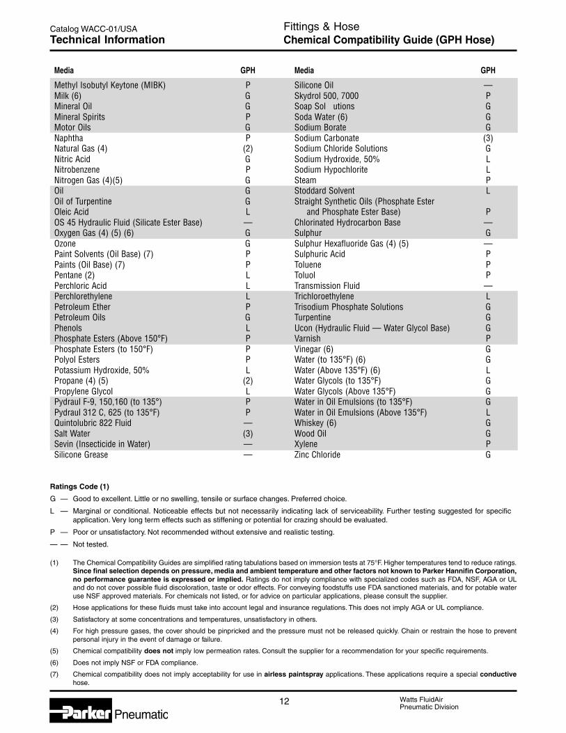
Watts FluidAirPneumatic Division
Pneumatic12
Catalog WACC-01/USA
Ratings Code (1)
G — Good to excellent. Little or no swelling, tensile or surface changes. Preferred choice.
L — Marginal or conditional. Noticeable effects but not necessarily indicating lack of serviceability. Further testing suggested for specificapplication. Very long term effects such as stiffening or potential for crazing should be evaluated.
P — Poor or unsatisfactory. Not recommended without extensive and realistic testing.
— — Not tested.
Fittings & HoseChemical Compatibility Guide (GPH Hose)Technical Information
(1) The Chemical Compatibility Guides are simplified rating tabulations based on immersion tests at 75°F. Higher temperatures tend to reduce ratings.Since final selection depends on pressure, media and ambient temperature and other factors not known to Parker Hannifin Corporation,no performance guarantee is expressed or implied. Ratings do not imply compliance with specialized codes such as FDA, NSF, AGA or ULand do not cover possible fluid discoloration, taste or odor effects. For conveying foodstuffs use FDA sanctioned materials, and for potable wateruse NSF approved materials. For chemicals not listed, or for advice on particular applications, please consult the supplier.
(2) Hose applications for these fluids must take into account legal and insurance regulations. This does not imply AGA or UL compliance.
(3) Satisfactory at some concentrations and temperatures, unsatisfactory in others.
(4) For high pressure gases, the cover should be pinpricked and the pressure must not be released quickly. Chain or restrain the hose to preventpersonal injury in the event of damage or failure.
(5) Chemical compatibility does not imply low permeation rates. Consult the supplier for a recommendation for your specific requirements.
(6) Does not imply NSF or FDA compliance.
(7) Chemical compatibility does not imply acceptability for use in airless paintspray applications. These applications require a special conductivehose.
Media GPH
Methyl Isobutyl Keytone (MIBK) PMilk (6) GMineral Oil GMineral Spirits PMotor Oils GNaphtha PNatural Gas (4) (2)Nitric Acid GNitrobenzene PNitrogen Gas (4)(5) GOil GOil of Turpentine GOleic Acid LOS 45 Hydraulic Fluid (Silicate Ester Base) —Oxygen Gas (4) (5) (6) GOzone GPaint Solvents (Oil Base) (7) PPaints (Oil Base) (7) PPentane (2) LPerchloric Acid LPerchlorethylene LPetroleum Ether PPetroleum Oils GPhenols LPhosphate Esters (Above 150°F) PPhosphate Esters (to 150°F) PPolyol Esters PPotassium Hydroxide, 50% LPropane (4) (5) (2)Propylene Glycol LPydraul F-9, 150,160 (to 135°) PPydraul 312 C, 625 (to 135°F) PQuintolubric 822 Fluid —Salt Water (3)Sevin (Insecticide in Water) —Silicone Grease —
Media GPH
Silicone Oil —Skydrol 500, 7000 PSoap Sol utions GSoda Water (6) GSodium Borate GSodium Carbonate (3)Sodium Chloride Solutions GSodium Hydroxide, 50% LSodium Hypochlorite LSteam PStoddard Solvent LStraight Synthetic Oils (Phosphate Ester and Phosphate Ester Base) PChlorinated Hydrocarbon Base —Sulphur GSulphur Hexafluoride Gas (4) (5) —Sulphuric Acid PToluene PToluol PTransmission Fluid —Trichloroethylene LTrisodium Phosphate Solutions GTurpentine GUcon (Hydraulic Fluid — Water Glycol Base) GVarnish PVinegar (6) GWater (to 135°F) (6) GWater (Above 135°F) (6) LWater Glycols (to 135°F) GWater Glycols (Above 135°F) GWater in Oil Emulsions (to 135°F) GWater in Oil Emulsions (Above 135°F) LWhiskey (6) GWood Oil GXylene PZinc Chloride G

Watts FluidAirPneumatic Division
F
Pneumatic
Fittings & Tubing
Section F
Pneumatic
P Fittings ............................................................... 2-11DB Fittings ........................................................... 12-17HB Fittings ........................................................... 18-22Prestolok / Prestolok II Fittings ............................ 23-34Pipe Fittings......................................................... 35-42PB Fittings ........................................................... 43-47FS Hose & Fittings .............................................. 48-51Polyethylene Tubing ............................................ 52-53
Nylon Tubing ....................................................... 54-55Polyurethane Tubing ................................................ 56Burst Pressure / Temperature Charts .................. 57-58Chemical Compatibility Guide (Brass) ................. 59-60Chemical Compatibility Guide (Thermoplastic) .... 61-62Chemical Compatibility Guide (Tubing) ............... 63-64Approvals ................................................................. 65Technical Information .......................................... 66-67

Watts FluidAirPneumatic Division
2
Catalog WACC-01/USA
Pneumatic
Copper, aluminum and nylon tubing:
Brass sleeves are recommended. Insert tube until itbottoms in the P fitting and tighten one wrench turn pastfinger-tight.
Maximum allowable metal tube wallthickness for use with P fittings:
1/8", 3/16", O.D. — no limitation, 1/4" O.D. — .035"5/16", 3/8", 1/2" O.D. — .049".
NomenclaturePart numbers are constructed from symbols that identifythe style and size of the fitting. The first series ofnumbers and letters identifies the style and type fitting.The second series of numbers describes the size.
Example:66 P -4 -2
Female Connector(Tube to female pipe)P Fitting1/4" (4/16) Tube O.D.1/8" (2/16) Pipe Thread
SizesTube sizes are determined by the number of sixteenthsof an inch in the tube O.D.
AdvantagesA compact brass compression fitting designed to speedany installation. Body, nut and sleeve are furnishedpreassembled, ready for installation. An exclusive acetalcopolymer sleeve holds plastic tubing where it belongs,even when the system pressure exceeds the tubing burstpoint. P fitting sleeves have superior resilience to resistcreeping and stress caused from compression. Theblack acetal copolymer sleeve also resists ultra-violet rayattack and has excellent dimensional stability. P fittingnuts will rotate around the sleeve as it tightens to preventtwisting and weakening of the plastic tubing. P fittingscan be assembled and disassembled repeatedly.
MaterialsElbows and Tees: Brass Forgings: CA 377Connectors, Unions, Nuts: CA 360, CA 345Plastic Sleeves: Acetal Copolymer (Celcon®).
ApplicationsUse with Parker or other high-quality thermoplastictubing for pneumatic instrumentation circuits, lubricantand coolant lines, and applications with other gasesand liquids. For use with soft metal tubing and nylonthermoplastic tubing, use brass sleeve and nut assembly61PB.
Working Pressure and TemperatureRangesUp to 150 PSI from 0° to 150°F with thermoplastictubing. Up to 300 PSI from 0° to 175°F with soft metaltubing.
Assembly InstructionsPolyethylene, polyproplene and vinyl tubing:
1. Cut tubing squarely – maximum of 15° angleallowable.
2. Check that port or mating part is clean and free ofdebris.
3. Insert tube end until it bottoms in the fitting and tightenknurl / hex nut finger tight – plus one wrench turn.
Fittings & TubingP FittingsBasic Features
Tube Support O.D.
Tube *D1
Size Tube
Inches SupportO.D.
1/4 .1685/16 .1853/8 .2481/2 .373
*Note: No tube support for sizes 1/8" and 3/16".
D1
D

3 Watts FluidAirPneumatic Division
Catalog WACC-01/USA
F
Pneumatic
Fittings & TubingP FittingsPart Numbers & Dimensions
L
D
C HEX
L
D
C HEX
59P Plastic CapPart TubeNo. Size A L
59P-4 1/4 .247 .5059P-5 5/16 .307 .5359P-6 3/8 .372 .5659P-8 1/2 .497 .63
60P Acetal Plastic SleevePart TubeNo. Size A D L
60P-4 1/4 .334 .261 .33860P-5 5/16 .405 .321 .34060P-6 3/8 .465 .381 .36760P-8 1/2 .628 .514 .399
61P Nut and Sleeve AssemblyPart Tube Straight CNo. Size Thread Hex D L
61P-2* 1/8 5/16-24 3/8 .130 .3461P-3* 3/16 3/8-24 7/16 .192 .3761P-4 1/4 3/8-24 7/16 .261 .3861P-5 5/16 7/16-24 1/2 .321 .3461P-6 3/8 1/2-24 9/16 .380 .3861P-8 1/2 11/16-20 3/4 .514 .44
*Brass Sleeve
61PB* Nut and Sleeve AssemblyPart Tube Straight CNo. Size Thread Hex D L
61PB-4 1/4 3/8-24 7/16 .255 .3861PB-5 5/16 7/16-24 1/2 .318 .3461PB-6 3/8 1/2-24 9/16 .382 .3861PB-8 1/2 11/16-20 3/4 .507 .44*Brass Sleeve
61PN NutPart Tube Straight CNo. Size Thread Hex L
61PN-2 1/8 5/16-24 3/8 .3461PN-3 3/16 3/8-24 7/16 .3761PN-4 1/4 3/8-24 7/16 .3861PN-5 5/16 7/16-24 1/2 .3461PN-6 3/8 1/2-24 9/16 .3861PN-8 1/2 11/16-20 3/4 .44
L
A
L
D
C HEX
L
A D

Watts FluidAirPneumatic Division
4
Catalog WACC-01/USA
Pneumatic
Fittings & TubingP FittingsPart Numbers & Dimensions
LM
C HEX
D
LM
1 2
C HEX
D
LM
D
1 2
C HEX
LMP
C HEX
D
62P UnionPart Tube Straight C FlowNo. Size Thread Hex L M Dia. D62P-2* 1/8 5/16-24 5/16 1.08 .64 .09462P-3* 3/16 3/8-24 3/8 1.16 .73 .12562P-4 1/4 3/8-24 3/8 1.17 .96 .12562P-5 5/16 7/16-24 7/16 1.16 .96 .14462P-6 3/8 1/2-24 1/2 1.23 .99 .20462P-8 1/2 11/16-20 11/16 1.47 1.24 .323*Brass Sleeve, No Tube Support
62P Union Reducer1 2 1 2
Part Tube Tube Straight Straight C FlowNo. Size Size Thread Thread Hex L M Dia. D62P-6-4 1/4 3/8 3/8-24 1/2-24 1/2 1.22 .99 .125
62PBH Bulkhead UnionPart Tube Straight C P Bulkhead FlowNo. Size Thread Hex Max. L M Hole Dia. Dia. D62PBH-4 1/4 3/8-24 9/16 .38 1.75 1.53 3/8 .12562PBH-5 5/16 7/16-24 5/8 .38 1.71 1.52 7/16 .14462PBH-6 3/8 1/2-24 11/16 .47 1.89 1.65 1/2 .20462PBH-8 1/2 11/16-20 7/8 .63 2.28 2.05 11/16 .323
62PCA Union(Tube to CA Fitting)
1 2Part Tube Straight Straight C FlowNo. Size Thread Thread Hex L M Dia. D62PCA-4 1/4 3/8-24 7/16-24 7/16 1.25 .89 .12562PCA-5 5/16 7/16-24 1/2-24 1/2 1.30 .92 .14462PCA-6 3/8 1/2-24 9/16-24 9/16 1.37 .98 .204

5 Watts FluidAirPneumatic Division
Catalog WACC-01/USA
F
Pneumatic
Fittings & TubingP FittingsPart Numbers & Dimensions
LM
C HEX
D
LM
P
C HEX
D
LM
D
C HEX
1 2
P
62PCABH Bulkhead Union(Tube to CA Fitting)
1 2Part Tube Straight Straight C P Bulkhead FlowNo. Size Thread Thread Hex Max. L M Hole Dia. Dia. D62PCABH-4 1/4 3/8-24 7/16-24 9/16 .38 1.81 1.45 3/8 .12562PCABH-6 3/8 1/2-24 9/16-24 11/16 .47 2.03 1.64 1/2 .204
62PTBH Bulkhead Union(Straight Through)Part Tube Straight C P Bulkhead FlowNo. Size Thread Hex Max. L M Hole Dia. Dia. D62PTBH-4 1/4 3/8-24 9/16 .31 1.19 .93 3/8 .26062PTBH-5 5/16 7/16-24 5/8 .31 1.19 .93 7/16 .32362PTBH-6 3/8 1/2-24 11/16 .34 1.26 .99 1/2 .387
66P Female ConnectorPart Tube Pipe Straight C FlowNo. Size Thread Thread Hex L M Dia. D66P-2-2* 1/8 1/8 5/16-24 9/16 .97 .75 .09466P-3-2* 3/16 1/8 3/8-24 9/16 1.00 .78 .12566P-3-4* 3/16 1/4 3/8-24 11/16 1.18 .96 .12566P-4-2 1/4 1/8 3/8-24 1/2 .97 .86 .12566P-4-4 1/4 1/4 3/8-24 5/8 1.18 1.07 .12566P-5-2 5/16 1/8 7/16-24 1/2 .97 .86 .14466P-6-4 3/8 1/4 1/2-24 5/8 1.18 1.07 .20466P-8-6 1/2 3/8 11/16-20 13/16 1.31 1.20 .323*Brass Sleeve, No Tube Support

Watts FluidAirPneumatic Division
6
Catalog WACC-01/USA
Pneumatic
Fittings & TubingP FittingsPart Numbers & Dimensions
LM
D
C HEX
68P Male ConnectorPart Tube Pipe Straight C FlowNo. Size Thread Thread Hex L M Dia. D68P-2-1* 1/8 1/16 5/16-24 11/32 1.00 .78 .09468P-2-2* 1/8 1/8 5/16-24 7/16 .99 .77 .09468P-3-1 3/16 1/16 3/8-24 7/16 1.09 .84 .09468P-3-2* 3/16 1/8 3/8-24 7/16 1.06 .84 .12568P-3-4* 3/16 1/4 3/8-24 9/16 1.25 1.03 .12568P-4-1 1/4 1/16 3/8-24 3/8 1.06 .95 .12568P-4-2 1/4 1/8 3/8-24 7/16 1.06 .95 .12568P-4-4 1/4 1/4 3/8-24 9/16 1.25 1.14 .12568P-4-6 1/4 3/8 3/8-24 11/16 1.28 1.17 .12568P-5-2 5/16 1/8 7/16-24 7/16 1.05 .95 .14468P-5-4 5/16 1/4 7/16-24 9/16 1.24 1.14 .14468P-6-2 3/8 1/8 1/2-24 1/2 1.10 .98 .20468P-6-4 3/8 1/4 1/2-24 9/16 1.29 1.17 .20468P-6-6 3/8 3/8 1/2-24 11/16 1.29 1.17 .20468P-8-4 1/2 1/4 11/16-20 11/16 1.46 1.29 .32068P-8-6 1/2 3/8 11/16-20 11/16 1.37 1.29 .32368P-2-10 x 32* 1/8 10-32 5/16-24 3/8 .86 .64 .09468P-4-10 x 32 1/4 10-32 3/8-24 3/8 .86 .75 .094*Brass Sleeve, No Tube Support
391P Pipe Coupler Body(Chrome Plated)
DPart Insert Pipe CNo. Dia. Thread Hex H L
391P-4-2 1/4 1/8 1/2 .91 1.29391P-4-4 1/4 1/4 9/16 .73 1.29391P-6-4 3/8 1/4 5/8 .85 1.41
392P Bulkhead Coupler Body(Chrome Plated)
DPart Tube Insert Straight C P BulkheadNo. Size Dia. Thread Hex Max. H L Hole Dia.392P-4-4 1/4 1/4 1/2-24 5/8 .84 .39 2.13 1/2392P-6-6 3/8 3/8 11/16-24 13/16 .93 .37 2.01 11/16
LM
D
C HEX
LH
C HEX
D
LP H
C HEX
D

7 Watts FluidAirPneumatic Division
Catalog WACC-01/USA
F
Pneumatic
Fittings & TubingP FittingsPart Numbers & Dimensions
H
C SQ
D F
ML
P H
F
C HEX
393P Through Type Insert(Chrome Plated)
DPart Tube Insert Straight C FlowNo. Size Dia. Thread Square H Dia. F393P-4-4 1/4 1/4 3/8-24 7/16 1.12 .125393P-6-6 3/8 3/8 1/2-24 1/2 1.34 .203
393PD Shut-off Type Insert(Chrome Plated)
DPart Tube Insert Straight C FlowNo. Size Dia. Thread Square H Dia. F393PD-4-4 1/4 1/4 3/8-24 7/16 1.61 .110393PD-6-6 3/8 3/8 1/2-24 1/2 1.45 .187
394P Single End Shut-off BulkheadQuick Coupler‡
(Chrome Plated)Part Tube Straight C P Bulkhead FlowNo. Size Thread Hex Max. H L M Hole Dia. Dia. F394P-4-4 1/4 1/2 - 24 5/8 .84 .39 3.28 2.13 1/2 .125394P-6-6 3/8 11/16-24 13/16 .93 .37 3.41 2.01 11/16 .203‡ Same as 392P-*-* and 393P-*-* Assembled.
H
C SQ
D F
H
C SQ
D F
393PD-4-4
393PD-6-6

Watts FluidAirPneumatic Division
8
Catalog WACC-01/USA
Pneumatic
ML
P H
C HEX
F F
ML
P H
C HEX
Fittings & TubingP FittingsPart Numbers & Dimensions
LM
C HEX
F
394PD Double End Shut-off BulkheadQuick Coupler‡
(Chrome Plated)Part Tube Straight C P Bulkhead FlowNo. Size Thread Hex Max. H L M Hole Dia. Dia. F394PD-4-4 1/4 1/2-24 5/8 .84 .39 3.77 2.13 1/2 .125394PD-6-6 3/8 11/16-24 13/16 .93 .47 3.48 2.01 11/16 .204‡ Same as 393PD-*-* and 392P-*-* Assembled.
398P Single End Shut-off Pipe ConnectorQuick Coupler‡
(Chrome Plated)Part Tube Pipe Straight C FlowNo. Size Thread Thread Hex L M Dia. F398P-4-2 1/4 1/8 3/8-24 1/2 2.45 1.32 .125398P-4-4 1/4 1/4 3/8-24 9/16 2.45 1.32 .125398P-6-4 3/8 1/4 1/2-24 5/8 2.80 1.46 .203‡ Same as 391P-*-* and 393P-*-* Assembled.
398PD Double End Shut-off Pipe ConnectorQuick Coupler‡
(Chrome Plated)Part Tube Pipe Straight C FlowNo. Size Thread Thread Hex L M Dia. F398PD-4-2 1/4 1/8 3/8-24 1/2 2.93 1.31 .125398PD-4-4 1/4 1/4 3/8-24 9/16 2.93 1.32 .125398PD-6-4 3/8 1/4 1/2-24 5/8 3.10 1.43 .204‡ Same as 391P-*-* and 393PD-*-* Assembled.
394PD-4-4 394PD-6-6
394PD-4-X 394PD-6-4
LM
C HEX
F
LM
C HEX
F

9 Watts FluidAirPneumatic Division
Catalog WACC-01/USA
F
Pneumatic
Fittings & TubingP FittingsPart Numbers & Dimensions
L
L1
L
M1
3
1 2
D
M M
D
N
LM
L
L
LM
M
M
D
164P-264P Union TeePart Tube Straight FlowNo. Size Thread L M Dia. D164P-2* 1/8 5/16-24 .83 .61 .094264P-3* 3/16 3/8-24 .83 .61 .125164P-4 1/4 3/8-24 .84 .73 .125164P-5 5/16 7/16-24 .83 .73 .144164P-6 3/8 1/2-24 .98 .86 .203164P-8 1/2 11/16-20 1.12 1.04 .323*Brass Sleeve, No Tube Support
164P Union Tee Combination Size1 2 3
Part Tube Tube Tube FlowNo. Size Size Size L L1 M M1 Dia. D164P-6-4A 3/8 3/8 1/4 .98 .90 .86 .79 .125
169P-269P Male ElbowPart Tube Pipe Straight FlowNo. Size Thread Thread L M N Dia. D169P-2-1 1/8 1/16 5/16-24 .88 .63 .69 .094269P-2-2* 1/8 1/8 5/16-24 .83 .61 .67 .094169P-3-1 3/16 1/16 3/8-24 .88 .63 .69 .094169P-3-2* 3/16 1/8 3/8-24 .83 .61 .69 .125169P-3-4* 3/16 1/4 3/8-24 .85 .63 .94 .125169P-4-1 1/4 1/16 3/8-24 .92 .58 .67 .130169P-4-2 1/4 1/8 3/8-24 .84 .73 .75 .121169P-4-4 1/4 1/4 3/8-24 .90 .79 .92 .125169P-4-6 1/4 3/8 3/8-24 .93 .84 1.08 .125169P-5-2 5/16 1/8 7/16-24 .87 .73 .68 .144169P-6-2 3/8 1/8 1/2-24 .93 .81 .73 .203169P-6-4 3/8 1/4 1/2-24 .98 .86 1.05 .203169P-6-6 3/8 3/8 1/2-24 .98 .86 1.08 .203169P-8-6 1/2 3/8 11/16-20 1.12 1.04 1.13 .323*Brass Sleeve, No Tube Support

Watts FluidAirPneumatic Division
10
Catalog WACC-01/USA
Pneumatic
Fittings & TubingP FittingsPart Numbers & Dimensions
D
N
LM
L
L
NM
M
D
D
N
LM
169LP Long Male ElbowPart Tube Pipe Straight FlowNo. Size Thread Thread L M N Dia. D169LP-4-4 1/4 1/4 3/8-24 .90 .79 1.38 .125
169PS Male Elbow SwivelPart Tube Pipe Straight C E FlowNo. Size Thread Thread Hex Hex L M N Dia. D169PS-4-2 1/4 1/8 3/8-24 3/8 7/16 .81 .59 .86 .121169PS-4-4 1/4 1/4 3/8-24 9/16 9/16 .91 .69 1.22 .125169PS-6-2 3/8 1/8 1/2-24 7/16 7/16 .88 .63 .90 .203169PS-6-4 3/8 1/4 1/2-24 9/16 9/16 .94 .69 1.22 .203169PS-6-6 3/8 3/8 1/2-24 9/16 11/16 .86 .60 1.19 .203169PS-8-6 1/2 3/8 11/16-20 1/2 11/16 1.03 .78 1.22 .323
170P Female ElbowPart Tube Pipe Straight FlowNo. Size Thread Thread L M N Dia. D170P-2-2* 1/8 1/8 5/16-24 .91 .69 .56 .094170P-3-2* 3/16 1/8 3/8-24 .91 .69 .56 .125170P-4-2 1/4 1/8 3/8-24 .90 .79 .56 .125170P-4-4 1/4 1/4 3/8-24 1.00 .89 .69 .125170P-6-4 3/8 1/4 1/2-24 1.01 .89 .69 .204170P-8-6 1/2 3/8 11/16-20 1.19 1.11 1.13 .323
*Brass Sleeve, No Tube Support
171P Male Run TeePart Tube Pipe Straight FlowNo. Size Thread Thread L M N Dia. D171P-2-2* 1/8 1/8 5/16-24 .82 .60 .67 .094171P-3-2* 3/16 1/8 3/8-24 .82 .60 .67 .125171P-4-2 1/4 1/8 3/8-24 .84 .73 .72 .125171P-4-4 1/4 1/4 3/8-24 .92 .81 .92 .125171P-5-2 5/16 1/8 7/16-24 .83 .73 .72 .144171P-6-4 3/8 1/4 1/2-24 .98 .86 1.03 .203171P-8-6 1/2 3/8 11/16-20 1.12 1.04 1.13 .323*Brass Sleeve, No Tube Support
D
N
LM
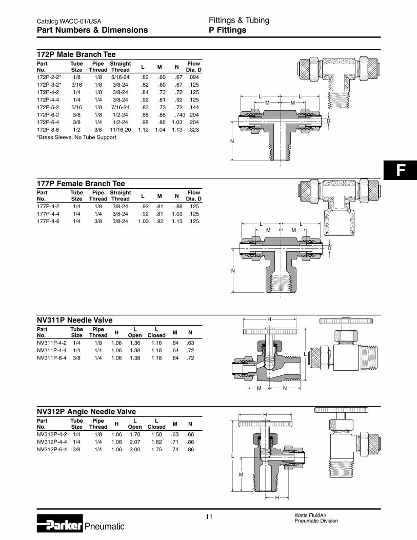
11 Watts FluidAirPneumatic Division
Catalog WACC-01/USA
F
Pneumatic
Fittings & TubingP FittingsPart Numbers & Dimensions
L
N
LM M
D
L
N
LM M
D
H
L
M N
H
H
L
M
172P Male Branch TeePart Tube Pipe Straight FlowNo. Size Thread Thread L M N Dia. D172P-2-2* 1/8 1/8 5/16-24 .82 .60 .67 .094172P-3-2* 3/16 1/8 3/8-24 .82 .60 .67 .125172P-4-2 1/4 1/8 3/8-24 .84 .73 .72 .125172P-4-4 1/4 1/4 3/8-24 .92 .81 .92 .125172P-5-2 5/16 1/8 7/16-24 .83 .73 .72 .144172P-6-2 3/8 1/8 1/2-24 .88 .86 .743 .204172P-6-4 3/8 1/4 1/2-24 .98 .86 1.03 .204172P-8-6 1/2 3/8 11/16-20 1.12 1.04 1.13 .323*Brass Sleeve, No Tube Support
177P Female Branch TeePart Tube Pipe Straight FlowNo. Size Thread Thread L M N Dia. D177P-4-2 1/4 1/8 3/8-24 .92 .81 .88 .125177P-4-4 1/4 1/4 3/8-24 .92 .81 1.03 .125177P-4-6 1/4 3/8 3/8-24 1.03 .92 1.13 .125
NV311P Needle ValvePart Tube Pipe L LNo. Size Thread H Open Closed M N
NV311P-4-2 1/4 1/8 1.06 1.36 1.16 .64 .63NV311P-4-4 1/4 1/4 1.06 1.38 1.18 .64 .72NV311P-6-4 3/8 1/4 1.06 1.38 1.18 .64 .72
NV312P Angle Needle ValvePart Tube Pipe L LNo. Size Thread H Open Closed M N
NV312P-4-2 1/4 1/8 1.06 1.70 1.50 .63 .68NV312P-4-4 1/4 1/4 1.06 2.07 1.82 .71 .86NV312P-6-4 3/8 1/4 1.06 2.00 1.75 .74 .86

Watts FluidAirPneumatic Division
12
Catalog WACC-01/USA
Pneumatic
NomenclaturePart numbers are constructed from symbols that identifythe style and size of the fitting. The first series ofnumbers and letters identifies the style and type fitting.The second series of numbers describes the size.
Example:
231 -8 -6
Run Tee (tubeto male pipe)
1/2" (8/16) Tube O.D.
3/8" (6/16) Pipe Thread
SizesTube sizes are determined by the number of sixteenthsof an inch in the tube O.D.
AdvantagesCompact one piece, push-on barbed fitting for a quick,economical way to connect polyethylene tubing.Extruded from CA 360 or CA 345 brass rod.
ApplicationsBecause of the many available variations in qualities ofpolyethylene tubing DB fittings are recommended for usewith Parker polyethylene tubing (or an equal grade).Parker tubing is highly resistant to environmental stresscracking which is necessary for long life when coupledwith expansion fittings.
Working Pressure andTemperature RangesIn tube sizes 1/4 to 3/8 working pressures up to150 PSI are practical at temperatures ranging from-65° to 90°F On 1/2" tube size, working pressures to100 PSI at temperatures ranging from -65° to 75°F.
Assembly InstructionsSimply push tube over the two barbs – be sure tubingis cut square.
Fittings & TubingDB FittingsBasic Features

13 Watts FluidAirPneumatic Division
Catalog WACC-01/USA
F
Pneumatic
Fittings & TubingDB FittingsPart Numbers & Dimensions
LM
C
LM
D
L
MD
LM
D
P
C HEX
20 PlugPart Tube Tube CNo. O.D. I.D. Dia. L M
20-4 1/4 .170 .290 .56 .4120-6 3/8 .250 .390 .68 .4420-8 1/2 .377 .577 .81 .56
22 UnionPart Tube Tube FlowNo. O.D. I.D. L M Dia. D22-5/32 5/32x5/32 .096x.096 .59 .28 .06222-4 1/4x1/4 .170x.170 .84 .41 .12022-6 3/8x3/8 .250x.250 .94 .44 .18722-8 1/2x1/2 .375x.375 1.19 .56 .312
22 Union ReducerPart Tube Tube FlowNo. O.D. I.D. L M Dia. D22-4-5/32 1/4x5/32 .170x.096 .72 .41 .06222-4-6 1/4x3/8 .170x.250 .88 .44 .12022-4-8 1/4x1/2 .170x.375 1.06 .56 .12022-6-8 3/8x1/2 .250x.375 1.06 .56 .187
22BH Bulkhead UnionPart Tube Tube Straight C P FlowNo. O.D. I.D. Thread Hex Max. L M Dia. D22BH-4-4 1/4 .170 5/16-24 7/16 .219 1.38 .78 .12022BH-6-6 3/8 .250 3/8-24 7/16 .375 1.63 1.00 .187

Watts FluidAirPneumatic Division
14
Catalog WACC-01/USA
Pneumatic
Fittings & TubingDB FittingsPart Numbers & Dimensions
L
D
C HEX
LD
C HEX
L
D21
C HEX
L
C HEX
D
26 Female ConnectorPart Tube Tube Pipe C FlowNo. O.D. I.D. Thread Hex L Dia. D26-5/32-2 5/32 .096 1/8 1/2 .79 .06226-4-2 1/4 .170 1/8 1/2 .91 .12026-6-2 3/8 .250 1/8 1/2 .93 .18726-6-4 3/8 .250 1/4 11/16 1.06 .187
27 Male ConnectorPart Tube Tube Pipe C FlowNo. O.D. I.D. Thread Hex L Dia. D27-1* 1/8 .062 10-32 UNF 1/4 .61 .05227-2* 1/4 .125 10-32 UNF 1/4 .74 .093*For vinyl tubing only.
28-4-5 Barb to Pipe AdapterPart Tube Tube Tube Tube Pipe C FlowNo. O.D. 1 I.D. 1 O.D. 2 I.D. 2 Thread Hex F Dia. D28-4-5/32-2 5/32 .096 1/4 .170 1/8 7/16 1.07 .062
28 Male ConnectorPart Tube Tube Pipe C FlowNo. O.D. I.D. Thread Hex L Dia. D28-5/32-2 5/32 .096 1/8 7/16 .84 .06228-4-1 1/4 .170 1/16 11/32 .93 .12028-4-2 1/4 .170 1/8 7/16 .97 .12028-4-4 1/4 .170 1/4 9/16 1.09 .12028-6-2 3/8 .250 1/8 7/16 1.00 .18728-6-4 3/8 .250 1/4 9/16 1.13 .18728-8-4 1/2 .375 1/4 9/16 1.25 .31228-8-6 1/2 .375 3/8 11/16 1.28 .31228-8-8 1/2 .375 1/2 7/8 1.44 .312

15 Watts FluidAirPneumatic Division
Catalog WACC-01/USA
F
Pneumatic
Fittings & TubingDB FittingsPart Numbers & Dimensions
220 Adapter TeePart Tube Tube Pipe FlowNo. O.D. I.D. Thread L M Dia. D220-4-2 1/4 .170 1/8 1.5 1.0 .120
224 Union TeePart Tube Tube FlowNo. O.D. I.D. L M Dia. D224-5/32 5/32 .096 1.000 .50 .062224-4 1/4 .170 1.250 .63 .120224-6 3/8 .250 1.375 .69 .187224-8 1/2 .375 1.625 .81 .312
224 Union Tee (Combination Sizes)Part Tube Tube Flow FlowNo. O.D. I.D. L M N Dia. D Dia. D1
224-4-4-5/32 1/4x5/32 .170x.096 1.25 .63 .50 .120 .062224-6-6-5/32 3/8x5/32 .250x.096 1.38 .69 .50 .187 .062224-6-6-4 3/8x1/4 .250x.170 1.38 .69 .62 .187 .120224-8-8-4 1/2x1/4 .375x.170 1.62 .81 .65 .312 .120224-8-8-6 1/2x3/8 .375x.250 1.62 .81 .69 .312 .187
225 Union ElbowPart Tube Tube FlowNo. O.D. I.D. L M Dia. D225-5/32 5/32 .096 .50 .50 .062225-4-4 1/4 .170 .63 .63 .120225-6-6 3/8 .250 .69 .69 .187225-8-8 1/2 .375 .81 .81 .312
228 Gauge TeePart Tube Tube Pipe FlowNo. O.D. I.D. Thread L M N Dia. D228-4-2 1/4 .170 1/8 1.91 .66 .44 .120
N
D
L
L
DM
L
N
D
M
L
D
LM
N
D1
D
LM
M

Watts FluidAirPneumatic Division
16
Catalog WACC-01/USA
Pneumatic
Fittings & TubingDB FittingsPart Numbers & Dimensions
D
L
M
N
D
LM
N
D
LM
N
D
N
M
D
M
M
12
229 Male ElbowPart Tube Tube Pipe FlowNo. O.D. I.D. Thread M N Dia. D229-5/32-2 5/32 .096 1/8 .56 .63 .062229-4-1 1/4 .170 1/16 .62 .60 .120229-4-2 1/4 .170 1/8 .69 .63 .120229-4-4 1/4 .170 1/4 .72 .72 .120229-6-2 3/8 .250 1/8 .69 .69 .187229-6-4 3/8 .250 1/4 .75 .75 .187229-8-6 1/2 .375 3/8 .94 .81 .312
229 Barb Adapter Elbow 90°Part Tube Tube Tube Tube Pipe FlowNo. O.D. 1 I.D. 1 O.D. 2 I.D. 2 Thread M Dia. D229-4-5/32-25/32 .096 1/4 .170 1/8 .78 .062
230 Female ElbowPart Tube Tube Pipe FlowNo. O.D. I.D. Thread L M N Dia. D230-4-2 1/4 .170 1/8 .91 .66 .44 .120230-6-4 3/8 .250 1/4 1.12 .78 .63 .187
231 Male Run TeePart Tube Tube Pipe FlowNo. O.D. I.D. Thread L M N Dia. D231-4-2 1/4 .170 1/8 1.28 .66 .69 .120231-6-2 3/8 .250 1/8 1.38 .69 .69 .187231-6-4 3/8 .250 1/4 1.44 .75 .75 .187
232 Male Branch TeePart Tube Tube Pipe FlowNo. O.D. I.D. Thread L M N Dia. D232-4-1 1/4 .170 1/16 1.33 .66 .65 .120232-4-2 1/4 .170 1/8 1.38 .69 .66 .120232-6-2 3/8 .250 1/8 1.38 .69 .69 .187232-6-4 3/8 .250 1/4 1.50 .75 .75 .187
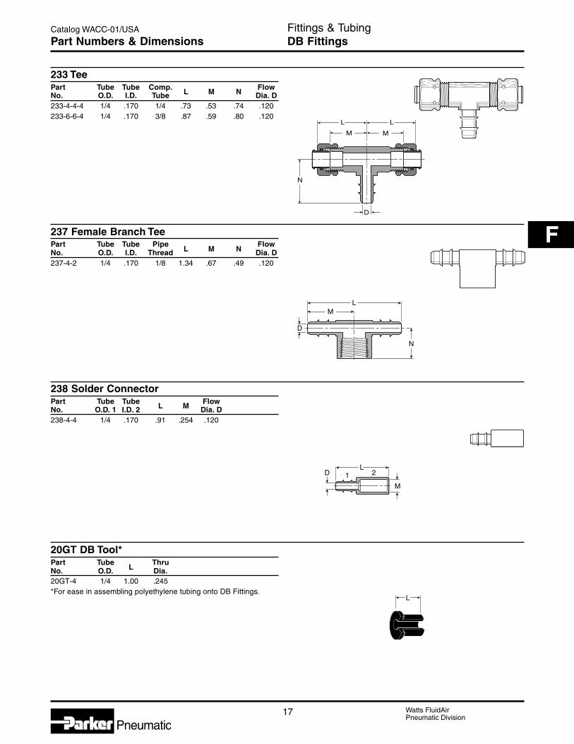
17 Watts FluidAirPneumatic Division
Catalog WACC-01/USA
F
Pneumatic
Fittings & TubingDB FittingsPart Numbers & Dimensions
233 TeePart Tube Tube Comp. FlowNo. O.D. I.D. Tube L M N Dia. D233-4-4-4 1/4 .170 1/4 .73 .53 .74 .120233-6-6-4 1/4 .170 3/8 .87 .59 .80 .120
237 Female Branch TeePart Tube Tube Pipe FlowNo. O.D. I.D. Thread L M N Dia. D237-4-2 1/4 .170 1/8 1.34 .67 .49 .120
238 Solder ConnectorPart Tube Tube FlowNo. O.D. 1 I.D. 2 L M Dia. D238-4-4 1/4 .170 .91 .254 .120
20GT DB Tool*Part Tube ThruNo. O.D. L Dia.20GT-4 1/4 1.00 .245*For ease in assembling polyethylene tubing onto DB Fittings.
N
MM
L
D
L
D
LM
N
DL
M
1 2
L

Watts FluidAirPneumatic Division
18
Catalog WACC-01/USA
Pneumatic
Fittings & TubingHB Brass FittingsBasic Features
NomenclaturePart numbers are constructed from symbols that identifythe style and size of the fitting. The first series ofnumbers and letters identifies the style and type fitting.The second series of numbers describes the size.
Example
128 HBL SV -6 -4
Female Ball End
Hose Barb
Swivel
3/8" (6/16) Hose I.D.
1/4" (4/16) F.M.N.P.S. Thread
SizesPipe sizes are determined by the number of sixteenthsof an inch in the pipe size.
AdvantagesAll HB fitting pipe threads are made to Drysealstandards. Connectors, unions, nuts and extrudedelbows and tees are machined from CA 360 and CA345 brass rod.
Temperature and Working PressureRangesFrom -40°F to 160°F at 150 PSI maximum.
Note: These fittings are intended for use with 97HChose clamp, similar type clamp or a crimpedferrule.
Assembly Instructions1. Cut hose cleanly and squarely to length.2. Slide clamp on hose.3. Lubricate hose. Push hose on fitting until hose
bottoms against stop ring or hex.4. Position hose clamp as shown below and secure
with a screwdriver or wrench. Maintain “A”dimension noted below for proper clamp positioning.
Hose Size Hose Clamp A3/16" 97 HC-3 1/4"1/4" 97 HC-3 1/4"5/16" 97 HC-6 1/4"3/8" 97 HC-6 1/8"1/2" 97 HC-8 1/8"5/8" 97 HC-12 1/8"3/4" 97 HC-12 1/8"
A

19 Watts FluidAirPneumatic Division
Catalog WACC-01/USA
F
Pneumatic
LM
DO.D. C
L
D
M
C HEX
Fittings & TubingHB Brass FittingsPart Numbers & Dimensions
68HB Beaded Hose Barb to Male PipeI.D.
Part Hose Pipe C FlowNo. Size Thread Hex L M Dia. D68HB-6-6 3/8 3/8 11/16 1.53 .78 .28168HB-8-4 1/2 1/4 5/8 1.56 .78 .40668HB-8-6 1/2 3/8 11/16 1.53 .78 .40668HB-10-6 5/8 3/8 3/4 1.62 .88 .50168HB-10-8 5/8 1/2 7/8 1.92 .88 .50168HB-12-8 3/4 1/2 7/8 1.98 .88 .56468HB-16-12 1 3/4 1-1/8 2.12 1.00 .750
97HC Steel Worm Drive ClampPart D C HNo. Max. Min. Hex Max. W
97HC-3 .62 .25 .25 1.00 .31
97HC-6 .87 .38 .31 1.40 .5097HC-8 1.00 .44 .31 1.53 .5097HC-12 1.25 .50 .31 1.80 .50
122HBL Hose MenderI.D.
Part Hose C FlowNo. Size Dia. L M O.D. Dia. D122HB-3* 3/16 5/16 1.44 .69 .227 .125122HBL-4 1/4 3/8 2.00 .97 .290 .187122HBL-5 5/16 7/16 2.00 .97 .353 .250
122HBL-6 3/8 1/2 2.00 .97 .415 .281122HBL-8 1/2 5/8 2.00 .97 .530 .375
*3 Barb design.
125HB Hose Barb to Male PipeI.D.
Part Hose Pipe C FlowNo. Size Thread Hex L M O.D. Dia. D125HB-2-2 1/8 1/8 7/16 1.07 .50 .185 .093125HB-3-2 3/16 1/8 7/16 1.25 .69 .227 .125
125HB-3-4 3/16 1/4 9/16 1.44 .69 .227 .125
D
C HEX
H
W
LM
C HEX
DO.D.

Watts FluidAirPneumatic Division
20
Catalog WACC-01/USA
Pneumatic
Fittings & TubingHB Brass FittingsPart Numbers & Dimensions
125HBL Hose Barb to Male PipeI.D.
Part Hose Pipe C FlowNo. Size Thread Hex L M O.D. Dia. D125HBL-4-2 1/4 1/8 7/16 1.54 .97 .290 .187
125HBL-4-4 1/4 1/4 9/16 1.72 .97 .290 .187125HBL-4-6 1/4 3/8 11/16 1.77 .97 .290 .187125HBL-5-2 5/16 1/8 7/16 1.54 .97 .353 .250
125HBL-5-4 5/16 1/4 9/16 1.72 .97 .353 .250125HBL-5-6 5/16 3/8 11/16 1.77 .97 .353 .250125HBL-6-2 3/8 1/8 7/16 1.54 .97 .415 .281
125HBL-6-4 3/8 1/4 9/16 1.72 .97 .415 .281125HBL-6-6 3/8 3/8 11/16 1.77 .97 .415 .281125HBL-6-8 3/8 1/2 7/8 1.97 .97 .415 .281
125HBL-8-4 1/2 1/4 9/16 1.72 .97 .530 .375125HBL-8-6 1/2 3/8 11/16 1.77 .97 .530 .375125HBL-8-8 1/2 1/2 7/8 1.97 .97 .530 .375
125HBL-8-12 1/2 3/4 1-1/16 1.98 .97 .530 .375125HBL-10-6 5/8 3/8 11/16 1.77 .97 .645 .468125HBL-10-8 5/8 1/2 7/8 1.97 .97 .645 .468
125HBL-10-12 5/8 3/4 1-1/16 1.98 .97 .645 .468125HBL-12-8 3/4 1/2 7/8 1.97 .97 .790 .562125HBL-12-12 3/4 3/4 1-1/16 1.98 .97 .790 .562
125HBL-16-12 1 3/4 1-1/16 2.18 1.17 1.03 .750125HBL-16-16 1 1 1-3/8 2.36 1.17 1.03 .875
126HBL Hose Barb to Female PipeI.D.
Part Hose Pipe C FlowNo. Size Thread Hex L M O.D. Dia. D126HBL-4-2 1/4 1/8 1/2 1.47 .97 .290 .187126HBL-4-4 1/4 1/4 11/16 1.58 .97 .290 .187126HBL-5-4 5/16 1/4 11/16 1.58 .97 .353 .250
126HBL-6-2 3/8 1/8 1/2 1.47 .97 .415 .281126HBL-6-4 3/8 1/4 11/16 1.58 .97 .415 .281126HBL-6-6 3/8 3/8 13/16 1.63 .97 .415 .281
126HBL-8-6 1/2 3/8 13/16 1.59 .97 .530 .375126HBL-8-8 1/2 1/2 1 1.73 .97 .530 .375
127HB Ball End Joint Adapter to Male Pipe(For use with 128HBLSV)
PipePart Thread Pipe C FlowNo. (NPSM) Thread Hex L Dia. D127HB-4-2 1/4 1/8 9/16 .91 .219127HB-4-4 1/4 1/4 9/16 1.10 .281
127HB-6-4 3/8 1/4 11/16 1.10 .312127HB-6-6 3/8 3/8 11/16 1.15 .406127HB-8-6 1/2 3/8 27/32 1.25 .406
127HB-8-8 1/2 1/2 27/32 1.50 .531
LM
C HEX
DO.D.
D
C HEX
L
LM
C HEX
DO.D.
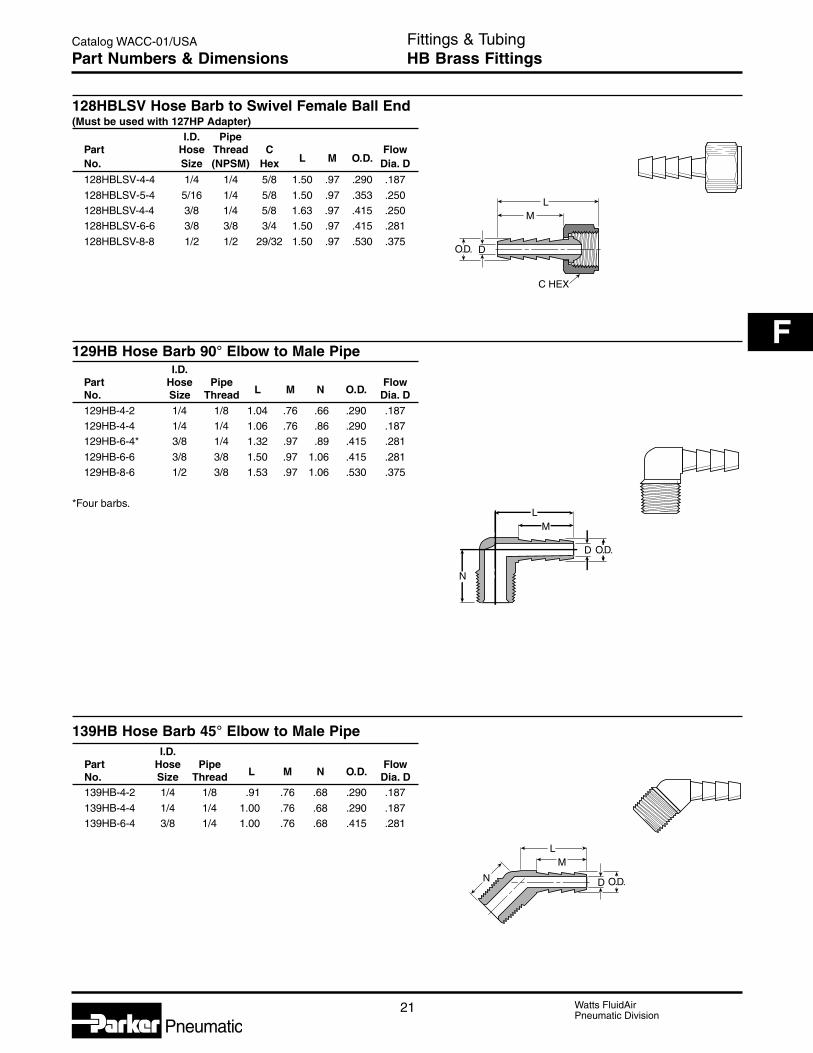
21 Watts FluidAirPneumatic Division
Catalog WACC-01/USA
F
Pneumatic
Fittings & TubingHB Brass FittingsPart Numbers & Dimensions
LM
C HEX
DO.D.
LM
D O.D.
N
128HBLSV Hose Barb to Swivel Female Ball End(Must be used with 127HP Adapter)
I.D. PipePart Hose Thread C FlowNo. Size (NPSM) Hex L M O.D. Dia. D
128HBLSV-4-4 1/4 1/4 5/8 1.50 .97 .290 .187
128HBLSV-5-4 5/16 1/4 5/8 1.50 .97 .353 .250128HBLSV-4-4 3/8 1/4 5/8 1.63 .97 .415 .250128HBLSV-6-6 3/8 3/8 3/4 1.50 .97 .415 .281
128HBLSV-8-8 1/2 1/2 29/32 1.50 .97 .530 .375
129HB Hose Barb 90° Elbow to Male PipeI.D.
Part Hose Pipe FlowNo. Size Thread L M N O.D. Dia. D129HB-4-2 1/4 1/8 1.04 .76 .66 .290 .187129HB-4-4 1/4 1/4 1.06 .76 .86 .290 .187129HB-6-4* 3/8 1/4 1.32 .97 .89 .415 .281
129HB-6-6 3/8 3/8 1.50 .97 1.06 .415 .281129HB-8-6 1/2 3/8 1.53 .97 1.06 .530 .375
*Four barbs.
139HB Hose Barb 45° Elbow to Male PipeI.D.
Part Hose Pipe FlowNo. Size Thread L M N O.D. Dia. D139HB-4-2 1/4 1/8 .91 .76 .68 .290 .187
139HB-4-4 1/4 1/4 1.00 .76 .68 .290 .187139HB-6-4 3/8 1/4 1.00 .76 .68 .415 .281
LM
D O.D.N

Watts FluidAirPneumatic Division
22
Catalog WACC-01/USA
Pneumatic
Fittings & TubingHB Brass FittingsPart Numbers & Dimensions
146HBLFSV Hose Barb to Swivel 45° Female Flare(Use with 45° Flare Fittings)
I.DPart Hose Straight C FlowNo. Size Thread Hex L M O.D. Dia. D146HBLFSV-4-4 1/4 7/16-20 9/16 1.55 .97 .290 .187146HBLFSV-4-6 1/4 5/8-18 3/4 1.72 .97 .290 .187
146HBLFSV-6-6 3/8 5/8-18 3/4 1.72 .97 .415 .281
269HB Beaded Hose Barb 90° Elbow Tube toMale Pipe
I.D.Part Hose Pipe FlowNo. Size Thread L M N Dia D269HB-6-6 3/8 3/8 1.19 .78 .88 .281
269HB-8-6 1/2 3/8 1.16 .78 1.08 .406269HB-10-4 5/8 1/4 1.13 .78 .99 .312269HB-10-6 5/8 3/8 1.16 .78 .99 .406
269H8-10-8 5/8 1/2 1.28 .78 1.25 .501269HB-12-8 3/4 1/2 1.28 .78 1.27 .625
LM
C HEX
DO.D.
LM
D
N

23 Watts FluidAirPneumatic Division
Catalog WACC-01/USA
F
Pneumatic
AdvantagesReady-to-use compact one-piece fitting for use withmost thermoplastic and copper tubing. This fitting isspecially designed for low pressure circuits where fastassembly, disassembly and reassembly is important. Nospecial tools are needed for assembly; just insert thetubing until it bottoms. Prestolok/Prestolok II is designedto be used with no tube support. Radial claws on thestainless steel grab ring grip the tubing securely toprovide retention. Brass Male pipe threads comestandard with a white acrylic sealant pre-applied (“W”prefix) swivels are featured on all male pipe threadedshapes for installation in tight places and for precisepositioning. Prestolok/Prestolok II should not be usedfor live swivel applications. The outside diameter of thetubing to be used with the fitting is marked on therelease button. The removable release button can becolor coded for ease of identification. Standard releasebutton is green.
MaterialsPrestolok Bodies: CA377, CA360, CA345Prestolok II Bodies: Glass Filled NylonO-Ring: Nitrile (other compounds available on request)Release Button: PolyacetalGrab Ring: Stainless Steel
ApplicationsUse with Parker Parflex series “E” polyethylene tubing,series “N” nylon tubing, series “U” polyurethane tubingor copper tubing. Perfectly adapted for use in a largevariety of industries, Prestolok II was designed as aneconomical alternative for pneumatic applications thatdo not require the higher pressure capacity of thestandard prestolok fittings, consult the factory with anyquestions regarding special product applications. Allapplications should be carefully tested through therange of conditions which may be encountered prior touse. For inch O.D. tubing
Working Pressure andTemperature RangesPrestolok: Zero to 200°F at up to 300 PSI depending
on tubing being used.Prestolok II: Zero to 150°F at up to 150 PSI depending
on tubing being used.Vacuum applications are dependent upon temperatureand type of tubing used.
Assembly Instructions1. Cut thermoplastic tubing squarely, using Parker Tube
Cutter PTC 001. Metal tubing should be cut squarelyand free of burrs. Be certain the port or mating partis clean and free of debris.
2. Insert tubing into fitting until it bottoms. A slighttwisting motion will ease the insertion. Pull on tubingto verify it is properly retained in the fitting.
3. To disassemble, simply push the release buttonagainst the body and remove tubing.
OrderBy part number and name.
NomenclaturePart numbers are constructed from symbols thatidentify the style and size of the fitting. The first series ofnumbers and letters identify the style and type fitting.The second series of numbers describe the size.
Example 69 PL –4 –2
Male ConnectorPrestolok1/4" (4/16) Tube O.D.1/8" (2/16) Pipe Thread
SizesTube sizes are determined by the number of sixteenthsof an inch in the tube O.D.
Fittings & TubingPrestolok / Prestolok II FittingsBasic Features

Watts FluidAirPneumatic Division
24
Catalog WACC-01/USA
Pneumatic
L
D O.D.
Fittings & TubingPrestolok / Prestolok II FittingsPart Numbers & Dimensions
L
2 1
D O.D.
O.D.
L
D
D
L
B
C HEX
P
D
L
32PL Equal UnionPart Tube FlowNo. Size O.D. L Dia. D32PL-2 1/8 .51 1.32 .0932PL-5/32 5/32 .51 1.32 .1232PL-3 3/16 .59 1.37 .1632PL-4 1/4 .59 1.37 .1932PL-5 5/16 .67 1.49 .2532PL-6 3/8 .83 1.76 .31
32PL Unequal UnionPart 1 Tube 2 Tube FlowNo. Size Size O.D. L Dia. D32PL-5/32-2 5/32 1/8 .51 1.32 .0932PL-4-2 1/4 1/8 .59 1.37 .0932PL-5-4 5/16 1/4 .67 1.47 .1932PL-6-4 3/8 1/4 .82 1.75 .19
62PL UnionPart TubeNo. Size O.D. L D62PL-2 1/8 .406 1.44 .09462PL-3 3/16 .437 1.35 .15662PL-5/32 5/32 .406 1.49 .12562PL-4 1/4 .500 1.51 .18862PL-5 5/16 .562 1.68 .25062PL-6 3/8 .625 1.68 .31262PL-8 1/2 .750 1.86 .375
62PLBH Bulkhead UnionPart Tube C pNo. Size B Hex Max. L D62PLBH-2 1/8 7/16 9/16 .39 1.44 .09462PLBH-5/32 5/32 7/16 9/16 .39 1.44 .12562PLBH-4 1/4 9/16 11/16 .29 1.51 .18862PLBH-5 5/16 5/8 3/4 .60 1.68 .25062PLBH-6 3/8 3/4 7/8 .54 1.68 .31262PLBH-8 1/2 7/8 1 .66 2.07 .375
63PL Double Male UnionPlastic BodyPart TubeNo. Size L D63PL-2 1/8 1.49 .07863PL-5/32 5/32 1.49 .10663PL-4 1/4 1.61 .18863PL-5 5/16 1.61 .23663PL-6 3/8 2.00 .29563PL-8 1/2 2.12 .374

25 Watts FluidAirPneumatic Division
Catalog WACC-01/USA
F
Pneumatic
Fittings & TubingPrestolok / Prestolok II FittingsPart Numbers & Dimensions
D
L
D
L
C HEX
P
D
L
2 1
D
LM
C HEX
66PL Female ConnectorPart Tube Pipe ThreadNo. Size (NPTF) L D66PL-2-2 1/8 1/8 1.18 .09466PL-3-2 3/16 1/8 1.16 .15666PL-5/32-2 5/32 1/8 1.18 .12566PL-5/32-4 5/32 1/4 1.39 .12566PL-4-2 1/4 1/8 1.21 .18866PL-4-4 1/4 1/4 1.42 .18866PL-5-2 5/16 1/8 1.27 .25066PL-5-4 5/16 1/4 1.47 .25066PL-6-4 3/8 1/4 1.46 .31266PL-6-6 3/8 3/8 1.51 .312
66PLBH Female BulkheadPipe
Part Tube Thread C P FlowNo. Size (NPTF) Hex Max. L Dia. D66PLBH-5/32-4 5/32 1/4 11/16 .24 1.38 .1366PLBH-4-4 1/4 1/4 11/16 .19 1.35 .1866PLBH-6-6 3/8 3/8 1 .22 1.44 .3166PLBH-8-6 1/2 3/8 1 1/4 .35 1.57 .34
67PPL Tube End ReducerPlastic BodyPart 1 Tube 2 TubeNo. Size Size L D67PPL-2-5/32 1/8 5/32 1.48 .07867PPL-2-4 1/8 1/4 1.48 .07867PPL-5/32-4 * 5/32 1/4 1.48 .11867PPL-5/32-5 * 5/32 5/16 1.41 .11867PPL-5/32-6 * 5/32 3/8 1.63 .11867PPL-4-5 1/4 5/16 1.52 .17767PPL-4-6 1/4 3/8 1.64 .17767PPL-4-8 1/4 1/2 1.72 .17767PPL-5-6 * 5/16 3/8 1.79 .23667PPL-6-8 3/8 1/2 1.92 .295* Parts supplied with black bodies and black release buttons
W68PL Male ConnectorPipe
Part Tube Thread CNo. Size (NPTF) Hex L M DW68PL-2-1 1/8 1/16 3/8 .85 .68 .094W68PL-2-2 1/8 1/8 7/16 .85 .68 .094W68PL-2-4 1/8 1/4 9/16 1.10 .68 .094W68PL-3-2 3/16 1/8 7/16 .92 .63 .156W68PL-3-4 3/16 1/4 9/16 1.10 .64 .156W68PL-5/32-2 5/32 1/8 7/16 .85 .69 .125W68PL-5/32-4 5/32 1/4 9/16 1.10 .69 .125W68PL-4-1 1/4 1/16 1/2 1.15 .71 .140W68PL-4-2 1/4 1/8 1/2 .97 .71 .188W68PL-4-4 1/4 1/4 9/16 1.10 .71 .188W68PL-4-6 1/4 3/8 3/4 1.14 .71 .188W68PL-5-2 5/16 1/8 9/16 1.23 .78 .234W68PL-5-4 5/16 1/4 9/16 1.11 .78 .250W68PL-5-6 5/16 3/8 11/16 1.12 .79 .250W68PL-6-2 3/8 1/8 11/16 1.26 .78 .234W68PL-6-4 3/8 1/4 11/16 1.14 .78 .312W68PL-6-6 3/8 3/8 11/16 1.09 .79 .312W68PL-6-8 3/8 1/2 7/8 1.34 .78 .312W68PL-8-4 1/2 1/4 13/16 1.52 .87 .344W68PL-8-6 1/2 3/8 13/16 1.31 .87 .344W68PL-8-8 1/2 1/2 7/8 1.43 .87 .375

Watts FluidAirPneumatic Division
26
Catalog WACC-01/USA
Pneumatic
D
LM
C HEX
Fittings & TubingPrestolok / Prestolok II FittingsPart Numbers & Dimensions
68PL-X-10x32 Male connectorPart Tube Thread C InternalNo. Size (UNF) Hex L M D Broach68PL-2-10X32 1/8 10-32 3/8 .93 .68 .094 .09468PL-5/32-10X32 5/32 10-32 13/32 .95 .69 .094 .09468PL-4-10X32 1/4 10-32 1/2 1.00 .71 .094 .094
PLHBF4-B BSPP Male ConnectorPipe
Part Tube Thread CNo. Size (BSPP) Hex L D3-1/8PLHBF4-B 3/16 1/8-28 11/16 .96 .1563-1/4PLHBF4-B 3/16 1/4-19 3/4 .97 .1564-1/8PLHBF4-B 1/4 1/8-28 11/16 1.13 .1884-1/4PLHBF4-B 1/4 1/4-19 3/4 1.13 .1884-3/8PLHBF4-B 1/4 3/8-19 7/8 1.13 .1886-1/4PLHBF4-B 3/8 1/4-19 3/4 1.26 .2566-3/8PLHBF4-B 3/8 3/8-19 7/8 1.26 .3126-1/2PLHBF4-B 3/8 1/2-14 1-1/16 1.26 .3128-3/8PLHBF4-B 1/2 3/8-19 7/8 1.41 .4528-1/2PLHBF4-B 1/2 1/2-14 1-1/16 1.37 .452
164PL Union TeePart TubeNo. Size L D164PL-2 1/8 .78 .094164PL-3 3/16 .79 .156164PL-5/32 5/32 .81 .125164PL-4 1/4 .94 .188164PL-5 5/16 .99 .250164PL-6 3/8 1.04 .312164PL-8 1/2 1.17 .375
364PL Union TeeComposite BodyPart Tube MountingNo. Size Hole Dia. L G D364PL-2 1/8 .13 .71 .52 .094364PL-5/32 5/32 .13 .71 .52 .125364PL-3 3/16 .17 .76 .64 .156364PL-4 1/4 .17 .76 .64 .188364PL-5 5/16 .17 .84 .71 .250364PL-6 3/8 .17 1.04 .83 .312364PL-8 1/2 .17 1.30 .99 .344
D
L
L
L
D
L
C HEX
D
L
G
L
L

27 Watts FluidAirPneumatic Division
Catalog WACC-01/USA
F
Pneumatic
C HEX
D
L
N
169PL-X-10/32
Fittings & TubingPrestolok / Prestolok II FittingsPart Numbers & Dimensions
D
L
L
D
L
N
D
165PL Union ElbowPart TubeNo. Size L D165PL-2 1/8 .77 .094165PL-5/32 5/32 .79 .125165PL-4 1/4 .86 .188165PL-5 5/16 .97 .250165PL-6 3/8 1.03 .312165PL-8 1/2 1.17 .375
365PL Union ElbowComposite BodyPart Tube MountingNo. Size Hole Dia. L D365PL-2 1/8 .13 .71 .094365PL-3 3/16 .17 .76 .156365PL-5/32 5/32 .13 .71 .125365PL-4 1/4 .17 .76 .188365PL-5 5/16 .17 .84 .250365PL-6 3/8 .17 1.04 .312365PL-8 1/2 .17 1.03 .344
W169PL Male Elbow Swivel 90°Pipe
Part Tube Thread CNo. Size (NPTF) Hex L N DW169PL-2-2 1/8 1/8 7/16 .78 1.22 .094169PL-2-10X32 1/8 10-32 3/8 .78 1.02 .094W169PL-2-4 1/8 1/4 9/16 .78 1.40 .094W169PL-3-2 3/16 1/8 7/16 .79 1.16 .156W169PL-5/32-2 5/32 1/8 7/16 .80 1.24 .109W169PL-5/32-4 5/32 1/4 9/16 .81 1.42 .109169PL-5/32-10X32 5/32 10-32 3/8 .81 1.04 .094W169PL-4-2 1/4 1/8 7/16 .86 1.13 .172W169PL-4-4 1/4 1/4 9/16 .86 1.31 .172W169PL-4-6 1/4 3/8 3/4 .86 1.35 .172169PL-4-10X32 1/4 10-32 7/16 .86 .94 .094W169PL-5-2 5/16 1/8 1/2 .99 1.42 .234W169PL-5-4 5/16 1/4 9/16 .99 1.60 .234W169PL-6-2 3/8 1/8 9/16 1.04 1.49 .297W169PL-6-4 3/8 1/4 9/16 1.04 1.66 .297W169PL-6-6 3/8 3/8 11/16 1.04 1.70 .297W169PL-6-8 3/8 1/2 7/8 1.04 1.89 .297W169PL-8-4 1/2 1/4 11/16 1.17 1.74 .344W169PL-8-6 1/2 3/8 3/4 1.17 1.77 .375W169PL-8-8 1/2 1/2 7/8 1.16 1.97 .375
D
L
L
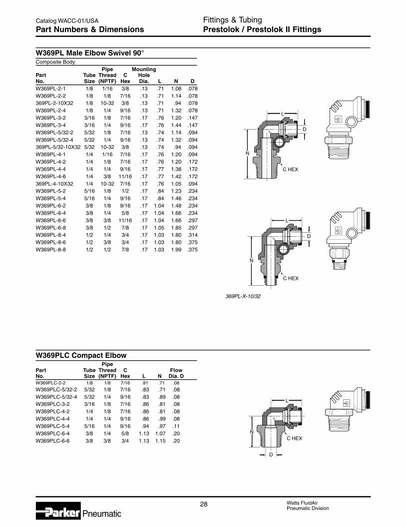
Watts FluidAirPneumatic Division
28
Catalog WACC-01/USA
Pneumatic
Fittings & TubingPrestolok / Prestolok II FittingsPart Numbers & Dimensions
369PL-X-10/32
W369PL Male Elbow Swivel 90°Composite Body
Pipe MountingPart Tube Thread C HoleNo. Size (NPTF) Hex Dia. L N DW369PL-2-1 1/8 1/16 3/8 .13 .71 1.08 .078W369PL-2-2 1/8 1/8 7/16 .13 .71 1.14 .078369PL-2-10X32 1/8 10-32 3/8 .13 .71 .94 .078W369PL-2-4 1/8 1/4 9/16 .13 .71 1.32 .078W369PL-3-2 3/16 1/8 7/16 .17 .76 1.20 .147W369PL-3-4 3/16 1/4 9/16 .17 .76 1.44 .147W369PL-5/32-2 5/32 1/8 7/16 .13 .74 1.14 .094W369PL-5/32-4 5/32 1/4 9/16 .13 .74 1.32 .094369PL-5/32-10X32 5/32 10-32 3/8 .13 .74 .94 .094W369PL-4-1 1/4 1/16 7/16 .17 .76 1.20 .094W369PL-4-2 1/4 1/8 7/16 .17 .76 1.20 .172W369PL-4-4 1/4 1/4 9/16 .17 .77 1.38 .172W369PL-4-6 1/4 3/8 11/16 .17 .77 1.42 .172369PL-4-10X32 1/4 10-32 7/16 .17 .76 1.05 .094W369PL-5-2 5/16 1/8 1/2 .17 .84 1.23 .234W369PL-5-4 5/16 1/4 9/16 .17 .84 1.46 .234W369PL-6-2 3/8 1/8 9/16 .17 1.04 1.48 .234W369PL-6-4 3/8 1/4 5/8 .17 1.04 1.66 .234W369PL-6-6 3/8 3/8 11/16 .17 1.04 1.66 .297W369PL-6-8 3/8 1/2 7/8 .17 1.05 1.85 .297W369PL-8-4 1/2 1/4 3/4 .17 1.03 1.80 .314W369PL-8-6 1/2 3/8 3/4 .17 1.03 1.80 .375W369PL-8-8 1/2 1/2 7/8 .17 1.03 1.99 .375
W369PLC Compact ElbowPipe
Part Tube Thread C FlowNo. Size (NPTF) Hex L N Dia. DW369PLC-2-2 1/8 1/8 7/16 .81 .71 .08
W369PLC-5/32-2 5/32 1/8 7/16 .83 .71 .08W369PLC-5/32-4 5/32 1/4 9/16 .83 .89 .08W369PLC-3-2 3/16 1/8 7/16 .86 .81 .08W369PLC-4-2 1/4 1/8 7/16 .86 .81 .08W369PLC-4-4 1/4 1/4 9/16 .86 .99 .08W369PLC-5-4 5/16 1/4 9/16 .94 .97 .11W369PLC-6-4 3/8 1/4 5/8 1.13 1.07 .20W369PLC-6-6 3/8 3/8 3/4 1.13 1.15 .20
C HEX
D
L
N
C HEX
D
L
N
D
NC HEX
L

29 Watts FluidAirPneumatic Division
Catalog WACC-01/USA
F
Pneumatic
Fittings & TubingPrestolok / Prestolok II FittingsPart Numbers & Dimensions
C HEX
D
L
N
C HEX
D
L
N
D
L
N
D
PLE2BF4-K BSPP Male Ebow SwivelComposite Body
Pipe MountingPart Tube Thread C HoleNo. Size (BSPP) Hex Dia. L N D3-1/8PLE2BF4-K 3/16 1/8-28 11/16 .17 .76 1.17 .1473-1/4PLE2BF4-K 3/16 1/4-19 3/4 .17 .76 1.31 .1474-1/8PLE2BF4-K 1/4 1/8-28 11/16 .17 .76 1.06 .1804-1/4PLE2BF4-K 1/4 1/4-19 3/4 .17 .76 1.31 .1724-3/8PLE2BF4-K 1/4 3/8-19 7/8 .17 .76 1.31 .1826-1/4PLE2BF4-K 3/8 1/4-19 3/4 .17 1.04 1.57 .2976-3/8PLE2BF4-K 3/8 3/8-19 7/8 .17 1.04 1.68 .2976-1/2PLE2BF4-K 3/8 1/2-14 1-1/16 .17 1.04 1.85 .2978-3/8PLE2BF4-K 1/2 3/8-19 7/8 .17 1.03 1.63 .4068-1/2PLE2BF4-K 1/2 1/2-19 1-1/16 .17 1.03 1.78 .406
W369PLX Male Elbow Swivel 90°Composite Body
Pipe MountingPart Tube Thread C HoleNo. Size (NPTF) Hex Dia. L N DW369PLX-2-2 1/8 1/8 7/16 .13 .73 1.74 .080W369PLX-2-4 1/8 1/4 9/16 .13 .73 1.74 .080W369PLX-3-2 3/16 1/8 7/16 .17 .76 1.88 .150W369PLX-3-4 3/16 1/4 9/16 .17 .76 1.88 .150W369PLX-3-6 3/16 3/8 11/16 .17 .76 1.88 .150W369PLX-4-2 1/4 1/8 7/16 .17 .76 1.88 .170W369PLX-4-4 1/4 1/4 9/16 .17 .76 1.88 .170W369PLX-4-6 1/4 3/8 11/16 .17 .76 1.88 .170369PLX-5/32-0 5/32 10-32 3/8 .13 .73 1.54 .090W369PLX-5/32-2 5/32 1/8 7/16 .13 .73 1.54 .090W369PLX-5/32-4 5/32 1/4 9/16 .13 .73 1.54 .090W369PLX-5-2 5/16 1/8 9/16 .17 .84 1.99 .223W369PLX-5-4 5/16 1/4 9/16 .17 .84 1.99 .230W369PLX-5-6 5/16 3/8 11/16 .17 .84 1.99 .230W369PLX-6-4 3/8 1/4 5/8 .17 1.04 2.56 .223W369PLX-6-6 3/8 3/8 11/16 .17 1.04 2.56 .330W369PLX-6-8 3/8 1/2 7/8 .17 1.04 2.56 .300W369PLX-8-4 1/2 1/4 3/4 .17 1.03 2.80 .310W369PLX-8-6 1/2 3/8 3/4 .17 1.03 2.80 .340W369PLX-8-8 1/2 1/2 7/8 .17 1.03 2.80 .340
W169PLNS Male elbow 90°Pipe
Part Tube ThreadNo. Size (NPTF) L N DW169PLNS-2-2 1/8 1/8 .78 .68 .094W169PLNS-5/32-2 5/32 1/8 .81 .68 .125W169PLNS-5/32-4 5/32 1/4 .81 .89 .125W169PLNS-4-2 1/4 1/8 .86 .69 .188W169PLNS-4-4 1/4 1/4 .96 .89 .188W169PLNS-5-2 5/16 1/8 .98 .78 .234W169PLNS-5-4 5/16 1/4 1.02 .97 .250W169PLNS-6-4 3/8 1/4 1.04 .97 .312W169PLNS-6-6 3/8 3/8 1.11 1.09 .312W169PLNS-6-8 3/8 1/2 1.20 1.26 .312W169PLNS-8-6 1/2 3/8 1.31 1.15 .375W169PLNS-8-8 1/2 1/2 1.31 1.31 .375
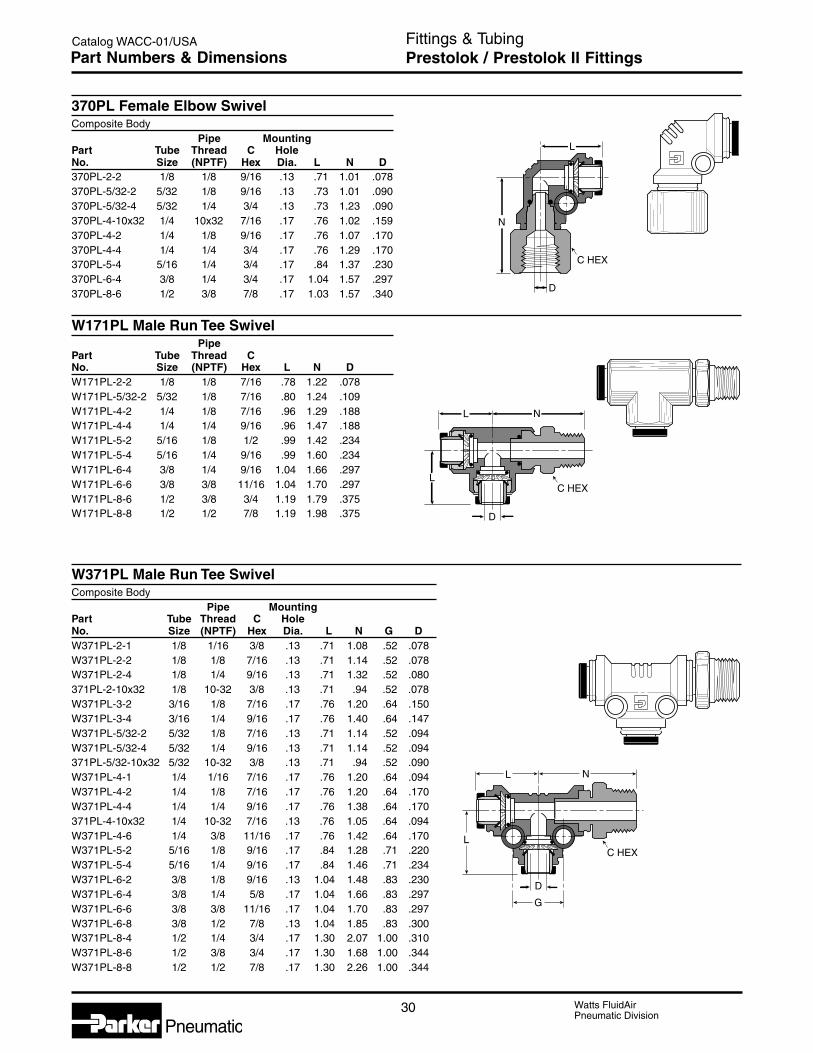
Watts FluidAirPneumatic Division
30
Catalog WACC-01/USA
Pneumatic
Fittings & TubingPrestolok / Prestolok II FittingsPart Numbers & Dimensions
C HEX
D
L
N
D
C HEX
N
L
L
D
L
G
LC HEX
N
370PL Female Elbow SwivelComposite Body
Pipe MountingPart Tube Thread C HoleNo. Size (NPTF) Hex Dia. L N D370PL-2-2 1/8 1/8 9/16 .13 .71 1.01 .078370PL-5/32-2 5/32 1/8 9/16 .13 .73 1.01 .090370PL-5/32-4 5/32 1/4 3/4 .13 .73 1.23 .090370PL-4-10x32 1/4 10x32 7/16 .17 .76 1.02 .159370PL-4-2 1/4 1/8 9/16 .17 .76 1.07 .170370PL-4-4 1/4 1/4 3/4 .17 .76 1.29 .170370PL-5-4 5/16 1/4 3/4 .17 .84 1.37 .230370PL-6-4 3/8 1/4 3/4 .17 1.04 1.57 .297370PL-8-6 1/2 3/8 7/8 .17 1.03 1.57 .340
W171PL Male Run Tee SwivelPipe
Part Tube Thread CNo. Size (NPTF) Hex L N DW171PL-2-2 1/8 1/8 7/16 .78 1.22 .078W171PL-5/32-2 5/32 1/8 7/16 .80 1.24 .109W171PL-4-2 1/4 1/8 7/16 .96 1.29 .188W171PL-4-4 1/4 1/4 9/16 .96 1.47 .188W171PL-5-2 5/16 1/8 1/2 .99 1.42 .234W171PL-5-4 5/16 1/4 9/16 .99 1.60 .234W171PL-6-4 3/8 1/4 9/16 1.04 1.66 .297W171PL-6-6 3/8 3/8 11/16 1.04 1.70 .297W171PL-8-6 1/2 3/8 3/4 1.19 1.79 .375W171PL-8-8 1/2 1/2 7/8 1.19 1.98 .375
W371PL Male Run Tee SwivelComposite Body
Pipe MountingPart Tube Thread C HoleNo. Size (NPTF) Hex Dia. L N G DW371PL-2-1 1/8 1/16 3/8 .13 .71 1.08 .52 .078W371PL-2-2 1/8 1/8 7/16 .13 .71 1.14 .52 .078W371PL-2-4 1/8 1/4 9/16 .13 .71 1.32 .52 .080371PL-2-10x32 1/8 10-32 3/8 .13 .71 .94 .52 .078W371PL-3-2 3/16 1/8 7/16 .17 .76 1.20 .64 .150W371PL-3-4 3/16 1/4 9/16 .17 .76 1.40 .64 .147W371PL-5/32-2 5/32 1/8 7/16 .13 .71 1.14 .52 .094W371PL-5/32-4 5/32 1/4 9/16 .13 .71 1.14 .52 .094371PL-5/32-10x32 5/32 10-32 3/8 .13 .71 .94 .52 .090W371PL-4-1 1/4 1/16 7/16 .17 .76 1.20 .64 .094W371PL-4-2 1/4 1/8 7/16 .17 .76 1.20 .64 .170W371PL-4-4 1/4 1/4 9/16 .17 .76 1.38 .64 .170371PL-4-10x32 1/4 10-32 7/16 .13 .76 1.05 .64 .094W371PL-4-6 1/4 3/8 11/16 .17 .76 1.42 .64 .170W371PL-5-2 5/16 1/8 9/16 .17 .84 1.28 .71 .220W371PL-5-4 5/16 1/4 9/16 .17 .84 1.46 .71 .234W371PL-6-2 3/8 1/8 9/16 .13 1.04 1.48 .83 .230W371PL-6-4 3/8 1/4 5/8 .17 1.04 1.66 .83 .297W371PL-6-6 3/8 3/8 11/16 .17 1.04 1.70 .83 .297W371PL-6-8 3/8 1/2 7/8 .13 1.04 1.85 .83 .300W371PL-8-4 1/2 1/4 3/4 .17 1.30 2.07 1.00 .310W371PL-8-6 1/2 3/8 3/4 .17 1.30 1.68 1.00 .344W371PL-8-8 1/2 1/2 7/8 .17 1.30 2.26 1.00 .344

31 Watts FluidAirPneumatic Division
Catalog WACC-01/USA
F
Pneumatic
Fittings & TubingPrestolok / Prestolok II FittingsPart Numbers & Dimensions
PLR2BF4-K BSPP Male Run Tee SwivelComposite Body
Pipe MountingPart Tube Thread C HoleNo. Size (BSPP) Hex Dia. L N G D3-1/4PLR2BF4-K 3/16 1/4-19 3/4 .17 .76 1.31 .64 .1504-1/8PLR2BF4-K 1/4 1/8-28 11/16 .17 .76 1.06 .64 .1704-1/4PLR2BF4-K 1/4 1/4-19 3/4 .17 .76 1.31 .64 .1706-1/4PLR2BF4-K 3/8 1/4-19 3/4 .17 1.04 1.52 .83 .3006-3/8PLR2BF4-K 3/8 3/8-19 7/8 .17 1.04 1.68 .83 .3008-3/8PLR2BF4-K 1/2 3/8-19 7/8 .17 1.30 1.90 .99 .3408-1/2PLR2BF4-K 1/2 1/2-19 1-1/16 .17 1.30 2.05 .99 .340
W172PL Male Branch Tee SwivelPipe
Part Tube Thread CNo. Size (NPTF) Hex L N DW172PL-2-2 1/8 1/8 7/16 .78 1.22 .078W172PL-3-2 3/16 1/8 7/16 .78 1.17 .156W172PL-5/32-2 5/32 1/8 7/16 .80 1.24 .109W172PL-4-2 1/4 1/8 7/16 .96 1.26 .188W172PL-4-4 1/4 1/4 9/16 .96 1.44 .188W172PL-5-2 5/16 1/8 1/2 .99 1.42 .234W172PL-5-4 5/16 1/4 9/16 .99 1.60 .234W172PL-6-4 3/8 1/4 9/16 1.04 1.66 .297W172PL-6-6 3/8 3/8 11/16 1.04 1.70 .297W172PL-8-6 1/2 3/8 3/4 1.19 1.79 .375W172PL-8-8 1/2 1/2 7/8 1.19 1.98 .375
D
L L
C HEX
N
D
L
G
LC HEX
N

Watts FluidAirPneumatic Division
32
Catalog WACC-01/USA
Pneumatic
Fittings & TubingPrestolok / Prestolok II FittingsPart Numbers & Dimensions
SS372PL Male Branch Tee SwivelStainless Steel Componentry
Pipe MountingPart Tube Thread C HoleNo. Size (NPTF) Hex Dia. L N G DW372PL-2-1 1/8 1/16 3/8 .13 .71 1.08 .52 .078W372PL-2-2 1/8 1/8 7/16 .13 .71 1.14 .52 .078W372PL-2-4 1/8 1/4 9/16 .13 .70 1.32 .52 .080372PL-2-10X32 1/8 10-32 3/8 .13 .70 .94 .52 .080W372PL-3-2 3/16 1/8 7/16 .17 .76 1.20 .64 .147W372PL-3-4 3/16 1/4 9/16 .17 .76 1.40 .64 .147W372PL-5/32-2 5/32 1/8 7/16 .13 .71 1.14 .52 .094W372PL-5/32-4 5/32 1/4 9/16 .13 .68 1.32 .52 .090372PL-5/32-10x32 5/32 10-32 3/8 .13 .70 .94 .52 .090W372PL-4-1 1/4 1/16 7/16 .17 .76 1.20 .64 .094W372PL-4-2 1/4 1/8 7/16 .17 .76 1.20 .64 .170W372PL-4-4 1/4 1/4 9/16 .17 .76 1.38 .64 .170372PL-4-10x32 1/4 10-32 7/16 .17 .76 1.05 .64 .090W372PL-4-6 1/4 3/8 11/16 .17 .76 1.42 .64 .170W372PL-5-2 5/16 1/8 9/16 .17 .84 1.28 .71 .234W372PL-5-4 5/16 1/4 9/16 .17 .84 1.23 .71 .234W372PL-6-2 3/8 1/8 9/16 .17 1.03 1.48 .83 .230W372PL-6-4 3/8 1/4 5/8 .17 1.04 1.66 .83 .297W372PL-6-6 3/8 3/8 11/16 .17 1.04 1.66 .83 .297W372PL-6-8 3/8 1/2 7/8 .17 1.03 1.85 .83 .300W372PL-8-4 1/2 1/4 3/4 .17 1.30 2.07 .99 .310W372PL-8-6 1/2 3/8 3/4 .17 1.30 2.07 .99 .344W372PL-8-8 1/2 1/2 7/8 .17 1.30 2.26 .99 .344
PLS2BF4-K BSPP Male Branch Tee SwivelComposite Body
Pipe MountingPart Tube Thread C HoleNo. Size (BSPP) Hex Dia. L N G D3-1/8PLS2BF4-K 3/16 1/8-28 11/16 .17 .76 1.05 .64 .1503-1/4PLS2BF4-K 3/16 1/4-19 3/4 .17 .76 1.31 .64 .1504-1/8PLS2BF4-K 1/4 1/8-28 11/16 .17 .76 1.06 .64 .1804-1/4PLS2BF4-K 1/4 1/4-19 3/4 .17 .76 1.31 .64 .1706-1/4PLS2BF4-K 3/8 1/4-19 3/4 .17 1.04 1.57 .83 .3006-3/8PLS2BF4-K 3/8 3/8-19 7/8 .17 1.04 1.68 .83 .3006-1/2PLS2BF4-K 3/8 1/2-14 1-1/16 .17 1.04 1.83 .83 .3008-3/8PLS2BF4-K 1/2 3/8-19 7/8 .17 1.30 1.90 .99 .410
C HEX
N
D
L
G
L
C HEX
N
D
L
G
L
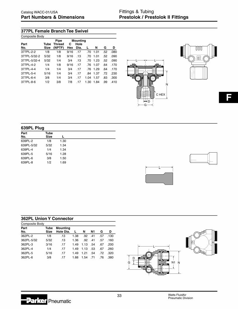
33 Watts FluidAirPneumatic Division
Catalog WACC-01/USA
F
Pneumatic
Fittings & TubingPrestolok / Prestolok II FittingsPart Numbers & Dimensions
377PL Female Branch Tee SwivelComposite Body
Pipe MountingPart Tube Thread C HoleNo. Size (NPTF) Hex Dia. L N G D377PL-2-2 1/8 1/8 9/16 .17 .70 1.01 .52 .080377PL-5/32-2 5/32 1/8 9/16 .13 .70 1.01 .52 .090377PL-5/32-4 5/32 1/4 3/4 .13 .70 1.23 .52 .090377PL-4-2 1/4 1/8 9/16 .17 .76 1.07 .64 .170377PL-4-4 1/4 1/4 3/4 .17 .76 1.29 .64 .170377PL-5-4 5/16 1/4 3/4 .17 .84 1.37 .72 .230377PL-6-4 3/8 1/4 3/4 .17 1.04 1.57 .83 .300377PL-8-6 1/2 3/8 7/8 .17 1.30 1.84 .99 .410
639PL PlugPart TubeNo. Size L639PL-2 1/8 1.30639PL-5/32 5/32 1.34639PL-4 1/4 1.34639PL-5 5/16 1.28639PL-6 3/8 1.50639PL-8 1/2 1.69
362PL Union Y ConnectorComposite BodyPart Tube MountingNo. Size Hole Dia. L N N1 G D362PL-2 1/8 .13 1.38 .92 .41 .57 .130362PL-5/32 5/32 .13 1.36 .92 .41 .57 .160362PL-3 3/16 .17 1.49 1.13 .54 .67 .200362PL-4 1/4 .17 1.49 1.13 .53 .67 .260362PL-5 5/16 .17 1.49 1.21 .54 .72 .320362PL-6 3/8 .17 1.88 1.54 .71 .76 .380
C HEX
D
N
L
G
L
L
D
G
L
NN1

Watts FluidAirPneumatic Division
34
Catalog WACC-01/USA
Pneumatic
Fittings & TubingPrestolok / Prestolok II FittingsPart Numbers & Dimensions
DG
L
NN1
W368PL Union Y Male ConnectorComposite BodyPart Tube Pipe MountingNo. Size Size G Hole Dia. L N N1 DW368PL-2-2 1/8 1/8 .57 .13 1.81 .91 .41 .080W368PL-2-4 1/8 1/4 .57 .13 1.98 .91 .41 .080368PL-5/32-10x32 5/32 10-32 .57 .13 1.60 .92 .41 .090W368PL-5/32-2 5/32 1/8 .57 .13 1.80 .92 .41 .090W368PL-5/32-4 5/32 1/4 .57 .13 1.98 .92 .41 .090368PL-3-10x32 3/16 10-32 .67 .17 1.77 1.13 .54 .094W368PL-3-2 3/16 1/8 .67 .17 1.92 1.13 .54 .150W368PL-3-4 3/16 1/4 .67 .17 2.16 1.13 .54 .150W368PL-3-6 3/16 3/8 .67 .17 2.16 1.13 .54 .147368PL-4-10x32 1/4 10-32 .67 .17 1.78 1.13 .53 .090W368PL-4-2 1/4 1/8 .67 .17 1.93 1.13 .53 .172W368PL-4-4 1/4 1/4 .67 .17 2.11 1.13 .53 .170W368PL-4-6 1/4 3/8 .67 .17 2.15 1.13 .53 .170W368PL-5-2 5/16 1/8 .72 .17 1.87 1.20 .54 .230W368PL-5-4 5/16 1/4 .72 .17 2.10 1.20 .54 .230W368PL-5-6 5/16 3/8 .72 .17 2.04 1.20 .54 .234W368PL-6-4 3/8 1/4 .76 .17 2.50 1.53 .71 .300W368PL-6-6 3/8 3/8 .76 .17 2.50 1.53 .71 .300W368PL-6-8 3/8 1/2 .76 .17 2.69 1.53 .71 .300

35 Watts FluidAirPneumatic Division
Catalog WACC-01/USA
F
Pneumatic
Fittings & TubingPipe FittingsBasic Features
AdvantagesAll pipe fitting threads are made to Dryseal standards.Connectors, unions, nuts and extruded elbows and teesare machined from CA 360 or CA 345 brass rod; forgedelbows and tees are machined from CA 377 brass.
ApprovalsMeets functional requirements of the SAE, J530, SAEJ531 and ASA.
ApplicationsUse with brass, copper, or iron pipe. Manufactured forlow and medium pressure line connection work.
Temperature and Working PressureRangesFrom -65°F to 250°F at 1000 PSI.
VibrationFair resistance to vibration and pipe movementdepending upon conditions.
NomenclaturePart numbers are constructed from symbols that identifythe style and size of the fitting. The first series ofnumbers and letters identifies the style and type fitting.The second series of numbers describes the size.
Example
2 214 P -2 -2Forging (1)Extrusion (2)45° Street ElbowPipe1/8" (2/16) Pipe Thread1/8" (2/16) Pipe Thread
SizesPipe sizes are determined by the number of sixteenthsof an inch in the pipe size.

Watts FluidAirPneumatic Division
36
Catalog WACC-01/USA
Pneumatic
L
P
D
B HEX C HEX
Fittings & TubingPipe FittingsPart Numbers & Dimensions
Anchor Connector 207ACBHPart Pipe Straight B C P FlowNo. Thread Thread Hex Hex Max. L Dia. D207ACBH-2 1/8 5/8-18 .88 .94 .80 1.50 .328207ACBH-4 1/4 3/4-16 1.00 1.12 .75 1.50 .422207ACBHS-4 1/4 3/4-16 1.00 1.00 .19 .94 .422
207ACBH-6 3/8 1.00-14 1.12 1.25 .50 1.31 .562207ACBH-8 1/2 1-1/8-14 1.25 1.38 .67 1.50 .688
Coupling 207PRef. SAE 130138
Part Pipe C FlowNo. Thread Hex L Dia. D207P-2 1/8 9/16 .75 .328207P-4 1/4 3/4 1.12 .422
207P-6 3/8 7/8 1.12 .562207P-8 1/2 1-1/16 1.50 .687207P-12 3/4 1-3/8 1.53 .900
Reducer Coupling 208PRef. SAE 130138
1 2Part Pipe Pipe C FlowNo. Thread Thread Hex L Dia. D208P-4-2 1/4 1/8 3/4 .97 .328
208P-6-4 3/8 1/4 7/8 1.16 .422208P-8-4 1/2 1/4 1-1/16 1.28 .422208P-8-6 1/2 3/8 1-1/16 1.38 .562
Bushing 209PRef. SAE 130140
1 2Part Pipe Pipe C FlowNo. Thread Thread Hex L Dia. D209P-4-2 1/8 1/4 9/16 .75 .328209P-6-2 1/8 3/8 11/16 .75 .328
209P-6-4 1/4 3/8 11/16 .75 .422209P-8-2 1/8 1/2 7/8 1.00 .328209P-8-4 1/4 1/2 7/8 1.00 .422
209P-8-6 3/8 1/2 7/8 1.00 .562209P-12-2 1/8 3/4 1-1/8 1.00 .328209P-12-4 1/4 3/4 1-1/8 1.00 .422
209P-12-6 3/8 3/4 1-1/8 1.00 .562209P-12-8 1/2 3/4 1-1/8 1.00 .688
L
D
C HEX
L
D
C HEX
21
L
C HEX
21
D

37 Watts FluidAirPneumatic Division
Catalog WACC-01/USA
F
Pneumatic
Fittings & TubingPipe FittingsPart Numbers & Dimensions
210P Lock NutPart Pipe CNo. Thread Hex L
210P-2 1/8 11/16 .19210P-4 1/4 7/8 .25210P-6 3/8 1 .25
210P-8 1/2 1-1/8 .25
211P Square-head PlugPart Pipe CNo. Thread Square L M
211P-2 1/8 9/32 .59 .25211P-4 1/4 3/8 .80 .30
211P-6 3/8 15/32 .80 .30211P-8 1/2 9/16 1.07 .39211P-12 3/4 5/8 1.14 .45
212P UnionPart Pipe C FlowNo. Thread Hex L Dia. D212P-4 1/4 1-3/16 1.53 .422
212P-6 3/8 1-1/4 1.79 .562
213P CapPart Pipe CNo. Thread Hex L
213P-2 1/8 9/16 .50213P-4 1/4 11/16 .63213P-6 3/8 13/16 .63
213P-8 1/2 1-1/16 .87
L
C HEX
L
C
M
L
C HEX
D
L
C HEX

Watts FluidAirPneumatic Division
38
Catalog WACC-01/USA
Pneumatic
Fittings & TubingPipe FittingsPart Numbers & Dimensions
215PN Close NipplePart Pipe FlowNo. Thread L Dia. D215PN-2 1/8 .75 .281
215PN-4 1/4 .88 .375215PN-6 3/8 1.00 .500215PN-8 1/2 1.13 .625
215PN-12 3/4 1.31 .750
215PNL Long NipplePart Pipe FlowNo. Thread L Dia. D215PNL-2-15 1/8 1-1/2 .250
215PNL-4-15 1/4 1-1/2 .375215PNL-6-15 3/8 1-1/2 .500215PNL-8-15 1/2 1-1/2 .625
215PNL-2-20 1/8 2 .250215PNL-4-20 1/4 2 .375215PNL-6-20 3/8 2 .500
215PNL-8-20 1/2 2 .625215PNL-2-25 1/8 2-1/2 .250215PNL-4-25 1/4 2-1/2 .375
215PNL-6-25 3/8 2-1/2 .500215PNL-8-25 1/2 2-1/2 .625215PNL-2-30 1/8 3 .250
215PNL-4-30 1/4 3 .375215PNL-6-30 3/8 3 .500215PNL-8-30 1/2 3 .625
215PNL-2-35 1/8 3-1/2 .250215PNL-4-35 1/4 3-1/2 .375215PNL-6-35 3/8 3-1/2 .500
215PNL-8-35 1/2 3-1/2 .625
216P Hex NippleRef. SAE 130137
Part Pipe C FlowNo. Thread Hex L Dia. D216P-2 1/8 7/16 .97 .220
216P-4 1/4 9/16 1.38 .314216P-6 3/8 11/16 1.41 .440216P-8 1/2 7/8 1.81 .564
216P-12 3/4 1-1/16 1.81 .752
216P Reducers1 2
Part Pipe Pipe C FlowNo. Thread Thread Hex L Dia. D
216P-4-2 1/4 1/8 9/16 1.19 .220216P-6-2 3/8 1/8 11/16 1.22 .220
216P-6-4 3/8 1/4 11/16 1.41 .314216P-8-4 1/2 1/4 7/8 1.62 .314216P-8-6 1/2 3/8 7/8 1.62 .440
216P-12-8 3/4 1/2 1-1/16 1.80 .564
L
D
L
D
L
C HEX
D
21
L
C HEX
D
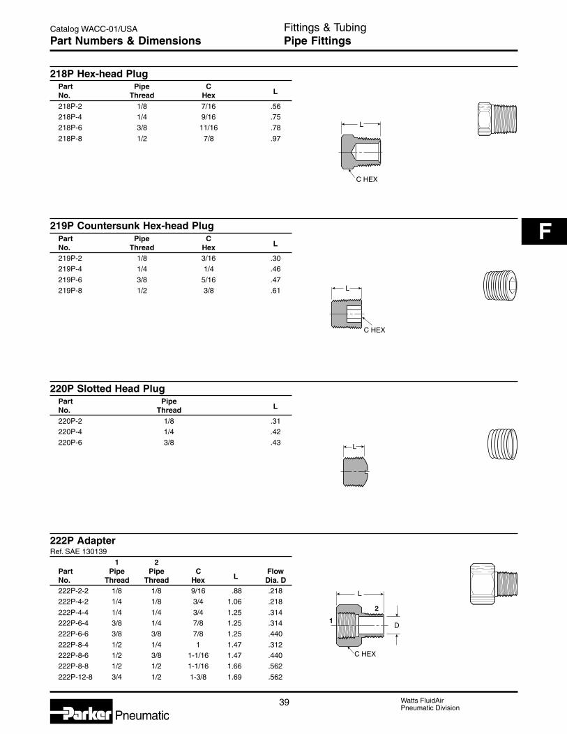
39 Watts FluidAirPneumatic Division
Catalog WACC-01/USA
F
Pneumatic
Fittings & TubingPipe FittingsPart Numbers & Dimensions
218P Hex-head PlugPart Pipe CNo. Thread Hex L
218P-2 1/8 7/16 .56218P-4 1/4 9/16 .75218P-6 3/8 11/16 .78
218P-8 1/2 7/8 .97
219P Countersunk Hex-head PlugPart Pipe CNo. Thread Hex L
219P-2 1/8 3/16 .30219P-4 1/4 1/4 .46
219P-6 3/8 5/16 .47219P-8 1/2 3/8 .61
220P Slotted Head PlugPart PipeNo. Thread L
220P-2 1/8 .31220P-4 1/4 .42220P-6 3/8 .43
222P AdapterRef. SAE 130139
1 2Part Pipe Pipe C FlowNo. Thread Thread Hex L Dia. D222P-2-2 1/8 1/8 9/16 .88 .218222P-4-2 1/4 1/8 3/4 1.06 .218
222P-4-4 1/4 1/4 3/4 1.25 .314222P-6-4 3/8 1/4 7/8 1.25 .314222P-6-6 3/8 3/8 7/8 1.25 .440
222P-8-4 1/2 1/4 1 1.47 .312222P-8-6 1/2 3/8 1-1/16 1.47 .440222P-8-8 1/2 1/2 1-1/16 1.66 .562
222P-12-8 3/4 1/2 1-3/8 1.69 .562
L
C HEX
L
C HEX
L
C HEX
D
2
1
L

Watts FluidAirPneumatic Division
40
Catalog WACC-01/USA
Pneumatic
M
DN
12
1200P-2200P Union Elbow 90°Ref. SAE 130238
Part PipeNo. Thread M Dia. D1200P-2-2 1/8 .56 .3282200P-2-2 1/8 .55 .328
1200P-4-4 1/4 .81 .4222200P-4-4 1/4 .78 .4222200P-6-6 3/8 .84 .563
2200P-8-8 1/2 1.07 .687
1202P-2202P Street Elbow 90°Ref. SAE 130239
1 2Part Pipe Pipe FlowNo. Thread Thread M N Dia. D1202P-2-2 1/8 1/8 .81 .56 .222202P-2-2 1/8 1/8 .62 .48 .222202PA-2-2* 1/8 1/8 .66 .48 .22
2202P-4-2 1/4 1/8 .72 .45 .231202P-4-4 1/4 1/4 1.08 .69 .312202P-4-4 1/4 1/4 .91 .45 .34
2202PA-4-4* 1/4 1/4 .91 .72 .421202P-6-6 3/8 3/8 1.25 .78 .422202P-6-6 3/8 3/8 .98 .54 .41
2202PA-6-6* 3/8 3/8 .97 .78 .432202P-8-8 1/2 1/2 1.25 1.03 .56* Meets SAE dimensions.
D
M
M
D
M
M
M
N
D
1
2
Fittings & TubingPipe FittingsPart Numbers & Dimensions
1202P
2202P
2200P
1200P

41 Watts FluidAirPneumatic Division
Catalog WACC-01/USA
F
Pneumatic
Fittings & TubingPipe FittingsPart Numbers & Dimensions
1203P-2203P Union TeeRef. SAE 130438
Part Pipe FlowNo. Thread L M Dia. D1203P-2 1/8 1.12 .56 .3282203P-2 1/8 1.08 .53 .3281203P-4 1/4 1.38 .69 .422
2203P-4 1/4 1.52 .76 .4222203P-6 3/8 1.68 .84 .5622203P-8 1/2 2.14 1.07 .688
2200PDE Drop-ear Elbow 90°Part PipeNo. Thread L M Dia. D2200PDE-2 1/8 1.38 1.00 .328
2201P Female Elbow 45°Part Pipe FlowNo. Thread M Dia. D2201P-2-2 1/8 .43 .328
M
M
D
L
M
D
L
M
M
D
M
M
D
L
2203P
1203P

Watts FluidAirPneumatic Division
42
Catalog WACC-01/USA
Pneumatic
Fittings & TubingPipe FittingsPart Numbers & Dimensions
2205P CrossPart Pipe FlowNo. Thread M Dia. D2205P-2 1/8 .53 .3282205P-4 1/4 .75 .421
2205P-6 3/8 .82 .562
2214P Street Elbow 45°Ref. SAE 130339
Part Pipe FlowNo. Thread M N Dia. D2214P-2-2 1/8 .38 .50 .220
2214P-4-4 1/4 .54 .70 .3142214P-6-6 3/8 .54 .78 .4402214P-8-8 1/2 .73 1.00 .562
2224P Male Branch TeeRef. SAE 130425
Part Pipe FlowNo. Thread L M N Dia. D2224P-2 1/8 1.06 .53 .66 .2202224P-4 1/4 1.52 .76 .91 .314
2224P-6 3/8 1.68 .84 .97 .438
2225P Street TeeRef. SAE 130424
Part Pipe FlowNo. Thread M N Dia. D2225P-2 1/8 .53 .66 .220
2225P-4 1/4 .76 .91 .3122225P-6 3/8 .84 .98 .4402225P-8 1/2 1.07 1.26 .564
M
M
D
M
N
D
L
N
M
D
M
M
N
D

43 Watts FluidAirPneumatic Division
Catalog WACC-01/USA
F
Pneumatic
Working PressuresPB thermoplastic fittings are generally used in systemswhere pressures do not exceed 125 psi. When used inexcess of 125 psi, these fittings, in all sizes, should betested by the customer in this particular application.
Operating pressures are governed by ambient and fluidtemperatures, type of fluid conveyed, hose or tubingused, clamping mechanism employed, and conditionsof mechanical abuse.
NomenclaturePart numbers are constructed from symbols that identifythe style and size of the fitting. Letters identify style andmaterial. Numbers identify size in 1/16’s of an inch.
Example:P 4 MC B 2
Polyethylene1/4" (4/16) Tube I.D.Style Male ConnectorBarb1/8" (2/16) Pipe Thread
AdvantagesPB thermoplastic fittings are precision injection moldedfrom high strength, chemically inert materials.
The specially engineered four barb design generatesthe maximum gripping and sealing power whencombined with a hose clamp. The unique barb designrequires the tube or hose to expand slightly to acceptthe fitting, providing a positive seal on the barbs.
Applications and ApprovalsPB thermoplastic fittings are widely used with clear vinyltubing, urethane tubing, and a variety of rubber tubingand hose. PB thermoplastic fittings meet FDA and NSFspecs for food contact and potable water.
These fittings are recommended in medical, pollutioncontrol, food and beverage applications. Other usesinclude irrigation, instrumentation, reverse osmosis anddeionized water systems.
Temperature RangeBlack Polyethylene: -65°F to 190°F (-54°C to 88°C)White or Black Nylon: -40°F to 200°F (-40°C to 93°C)
Fittings & TubingPB Thermoplastic FittingsBasic Features

Watts FluidAirPneumatic Division
44
Catalog WACC-01/USA
Pneumatic
EUB Union ElbowBlack
High Density TubeLinear White or Hose
Polyethylene Nylon I.D. O.D. O.D. FlowPart No. Part No. 1 2 1 2 L N Dia. D
P4EUB4 N4EUB4 1/4 1/4 .308 .308 1.002 1.256 .153
P6EUB6 N6EUB6 3/8 3/8 .425 .425 1.060 1.256 .247P8EUB4 N8EUB4 1/2 1/4 .550 .308 1.002 1.256 .153P8EUB6 N8EUB6 1/2 3/8 .550 .425 1.060 1.256 .247
P8EUB8 N8EUB8 1/2 1/2 .550 .550 1.123 1.256 .372P10EUB10 N10EUB10 5/8 5/8 .644 .644 1.170 1.256 .465P12EUB12 N12EUB12 3/4 3/4 .788 .788 1.242 1.256 .606
HPL Hex Head Pipe PlugBlack
High DensityLinear White
Polyethylene Nylon Pipe CPart No. Part No. Thread Hex L
P2HPL N2HPL 1/8 7/16 .660
P4HPL N4HPL 1/4 9/16 .880P6HPL N6HPL 3/8 11/16 .905P8HPL N8HPL 1/2 7/8 1.092
P12HPL N12HPL 3/4 1-1/8 1.115
HPN Hex Pipe NippleBlack
High DensityLinear White
Polyethylene Nylon Pipe ThreadC Flow FlowPart No. Part No. 1 2 Hex L Dia D1 Dia. D2
P2HPN2 N2HPN2 1/8 1/8 7/16 1.062 .187 .187P4HPN2 N4HPN2 1/4 1/8 9/16 1.281 .286 .187
P4HPN4 N4HPN4 1/4 1/4 9/16 1.469 .285 .285P6HPN2 N6HPN2 3/8 1/8 11/16 1.332 .406 .187P6HPN4 N6HPN4 3/8 1/4 11/16 1.488 .406 .285
P6HPN6 N6HPN6 3/8 3/8 11/16 1.500 .406 .406P8HPN2 N8HPN2 1/2 1/8 7/8 1.485 .618 .187P8HPN4 N8HPN4 1/2 1/4 7/8 1.687 .618 .285
P8HPN6 N8HPN6 1/2 3/8 7/8 1.687 .618 .406P8HPN8 N8HPN8 1/2 1/2 7/8 1.875 .618 .618P12HPN6 N12HPN6 3/4 3/8 1-1/8 1.703 .750 .408
P12HPN8 N12HPN8 3/4 1/2 1-1/8 1.891 .750 .618P12HPN12 N12HPN12 3/4 3/4 1-1/8 1.932 .750 .750
N
OD2
LD
OD1
L
C HEX
L
C HEX
D
Fittings & TubingPB Thermoplastic FittingsPart Numbers & Dimensions
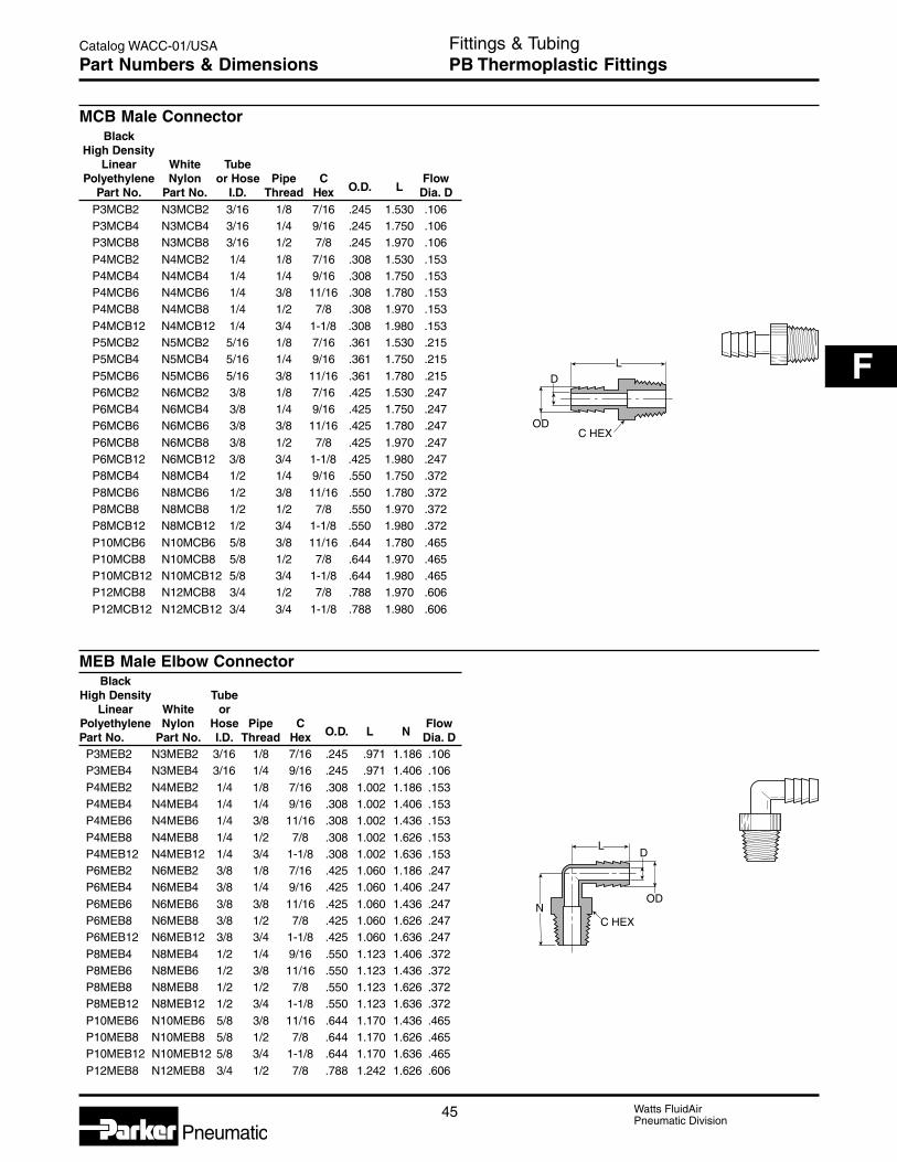
45 Watts FluidAirPneumatic Division
Catalog WACC-01/USA
F
Pneumatic
MCB Male ConnectorBlack
High DensityLinear White Tube
Polyethylene Nylon or Hose Pipe C FlowPart No. Part No. I.D. Thread Hex O.D. L Dia. D
P3MCB2 N3MCB2 3/16 1/8 7/16 .245 1.530 .106P3MCB4 N3MCB4 3/16 1/4 9/16 .245 1.750 .106P3MCB8 N3MCB8 3/16 1/2 7/8 .245 1.970 .106P4MCB2 N4MCB2 1/4 1/8 7/16 .308 1.530 .153P4MCB4 N4MCB4 1/4 1/4 9/16 .308 1.750 .153P4MCB6 N4MCB6 1/4 3/8 11/16 .308 1.780 .153P4MCB8 N4MCB8 1/4 1/2 7/8 .308 1.970 .153P4MCB12 N4MCB12 1/4 3/4 1-1/8 .308 1.980 .153P5MCB2 N5MCB2 5/16 1/8 7/16 .361 1.530 .215P5MCB4 N5MCB4 5/16 1/4 9/16 .361 1.750 .215P5MCB6 N5MCB6 5/16 3/8 11/16 .361 1.780 .215P6MCB2 N6MCB2 3/8 1/8 7/16 .425 1.530 .247P6MCB4 N6MCB4 3/8 1/4 9/16 .425 1.750 .247P6MCB6 N6MCB6 3/8 3/8 11/16 .425 1.780 .247P6MCB8 N6MCB8 3/8 1/2 7/8 .425 1.970 .247P6MCB12 N6MCB12 3/8 3/4 1-1/8 .425 1.980 .247P8MCB4 N8MCB4 1/2 1/4 9/16 .550 1.750 .372P8MCB6 N8MCB6 1/2 3/8 11/16 .550 1.780 .372P8MCB8 N8MCB8 1/2 1/2 7/8 .550 1.970 .372P8MCB12 N8MCB12 1/2 3/4 1-1/8 .550 1.980 .372P10MCB6 N10MCB6 5/8 3/8 11/16 .644 1.780 .465P10MCB8 N10MCB8 5/8 1/2 7/8 .644 1.970 .465P10MCB12 N10MCB12 5/8 3/4 1-1/8 .644 1.980 .465P12MCB8 N12MCB8 3/4 1/2 7/8 .788 1.970 .606P12MCB12 N12MCB12 3/4 3/4 1-1/8 .788 1.980 .606
MEB Male Elbow ConnectorBlack
High Density TubeLinear White or
Polyethylene Nylon Hose Pipe C FlowPart No. Part No. I.D. Thread Hex O.D. L N Dia. D
P3MEB2 N3MEB2 3/16 1/8 7/16 .245 .971 1.186 .106P3MEB4 N3MEB4 3/16 1/4 9/16 .245 .971 1.406 .106P4MEB2 N4MEB2 1/4 1/8 7/16 .308 1.002 1.186 .153P4MEB4 N4MEB4 1/4 1/4 9/16 .308 1.002 1.406 .153P4MEB6 N4MEB6 1/4 3/8 11/16 .308 1.002 1.436 .153P4MEB8 N4MEB8 1/4 1/2 7/8 .308 1.002 1.626 .153P4MEB12 N4MEB12 1/4 3/4 1-1/8 .308 1.002 1.636 .153P6MEB2 N6MEB2 3/8 1/8 7/16 .425 1.060 1.186 .247P6MEB4 N6MEB4 3/8 1/4 9/16 .425 1.060 1.406 .247P6MEB6 N6MEB6 3/8 3/8 11/16 .425 1.060 1.436 .247P6MEB8 N6MEB8 3/8 1/2 7/8 .425 1.060 1.626 .247P6MEB12 N6MEB12 3/8 3/4 1-1/8 .425 1.060 1.636 .247P8MEB4 N8MEB4 1/2 1/4 9/16 .550 1.123 1.406 .372P8MEB6 N8MEB6 1/2 3/8 11/16 .550 1.123 1.436 .372P8MEB8 N8MEB8 1/2 1/2 7/8 .550 1.123 1.626 .372P8MEB12 N8MEB12 1/2 3/4 1-1/8 .550 1.123 1.636 .372P10MEB6 N10MEB6 5/8 3/8 11/16 .644 1.170 1.436 .465P10MEB8 N10MEB8 5/8 1/2 7/8 .644 1.170 1.626 .465P10MEB12 N10MEB12 5/8 3/4 1-1/8 .644 1.170 1.636 .465P12MEB8 N12MEB8 3/4 1/2 7/8 .788 1.242 1.626 .606
C HEX
LD
OD
N
LD
OD
C HEX
Fittings & TubingPB Thermoplastic FittingsPart Numbers & Dimensions

Watts FluidAirPneumatic Division
46
Catalog WACC-01/USA
Pneumatic
MBT Male Branch TeeBlack
High Density TubeLlnear White or
Polyethylene Nylons Hose Pipe C FlowPart No. Part No. I.D. Thread Hex O.D. L N Dia. D
P3MTB2 N3MTB2 3/16 1/8 7/16 .245 1.941 1.187 .106P3MTB4 N3MTB4 3/16 1/4 9/16 .245 1.941 1.406 .106P4MTB2 N4MTB2 1/4 1/8 7/16 .308 2.004 1.187 .153
P4MTB4 N4MTB4 1/4 1/4 9/16 .308 2.004 1.406 .153P4MTB6 N4MTB6 1/4 3/8 11/16 .308 2.004 1.436 .153P6MTB4 N6MTB4 3/8 1/4 9/16 .425 2.121 1.406 .247
P6MTB6 N6MTB6 3/8 3/8 11/16 .425 2.121 1.436 .247P6MTB8 N6MTB8 3/8 1/2 7/8 .425 2.121 1.626 .247P8MTB4 N8MTB4 1/2 1/4 9/16 .550 2.246 1.406 .281
P8MTB6 N8MTB6 1/2 3/8 11/16 .550 2.246 1.436 .372P8MTB8 N8MTB8 1/2 1/2 7/8 .550 2.246 1.626 .372
TUB Union TeeBlack
High Density TubeLinear White or Hose
Polyethylene Nylon I.D. O.D. O.D. FlowPart No. Part No. 1 & 2 3 1 & 2 3 L N Dia. D
P2TUB2 N2TUB2 1/8 1/8 .141 .141 1.203 .594 .078
P3TUB3 N3TUB3 3/16 3/16 .245 .245 1.941 1.256 .106P4TUB4 N4TUB4 1/4 1/4 .308 .308 2.004 1.256 .153P5TUB5 N5TUB5 5/16 5/16 .361 .361 2.058 1.256 .215
P6TUB4 N6TUB4 3/8 1/4 .425 .308 2.121 1.256 .153P6TUB6 N6TUB6 3/8 3/8 .425 .425 2.134 1.256 .247P6TUB8 N6TUB8 3/8 1/2 .425 .550 2.121 1.256 .247
P8TUB6 N8TUB6 1/2 3/8 .550 .425 2.248 1.256 .247P8TUB8 N8TUB8 1/2 1/2 .550 .550 2.248 1.256 .372P10TUB10 N10TUB10 5/8 5/8 .644 .644 2.340 1.256 .465
ODN
LD
OD
C HEX
OD2N
LD
OD1
OD3
Fittings & TubingPB Thermoplastic FittingsPart Numbers & Dimensions

47 Watts FluidAirPneumatic Division
Catalog WACC-01/USA
F
Pneumatic
UCB Union ConnectorBlack Tube
High Density White or HosePolyethylene Nylon I.D. O.D. O.D. Flow
Part No. Part No. 1 2 1 2 L Dia. DP2UCB2 N2UCB2 1/8 1/8 .152 .152 .625 .050
P3UCB3 N3UCB3 3/16 3/16 .245 .245 1.750 .106P4UCB3 N4UCB3 1/4 3/16 .308 .245 1.750 .106P4UCB4 N4UCB4 1/4 1/4 .308 .308 1.750 .153
P5UCB5 N5UCB5 5/16 5/16 .361 .361 1.750 .215P6UCB4 N6UCB4 3/8 1/4 .425 .308 1.750 .153P6UCB6 N6UCB6 3/8 3/8 .425 .425 1.750 .247
P8UCB4 N8UCB4 1/2 1/4 .550 .308 1.750 .153P8UCB6 N8UCB6 1/2 3/8 .550 .425 1.750 .247P8UCB8 N8UCB8 1/2 1/2 .550 .550 1.750 .372
P10UCB6 N10UCB6 5/8 3/8 .644 .425 1.750 .247P10UCB8 N10UCB8 5/8 1/2 .644 .550 1.750 .372P10UCB10 N10UCB10 5/8 5/8 .644 .644 1.750 .465
OD2
LD
OD1
Fittings & TubingPB Thermoplastic FittingsPart Numbers & Dimensions

Watts FluidAirPneumatic Division
48
Catalog WACC-01/USA
Pneumatic
AdvantagesFS self retracting air hose is manufactured from anextremely tough, abrasion resistant nylon. FS hosehas excellent “memory” characteristics over a widetemperature range for long service life in the mostrugged applications. The SAFETY YELLOW color ofFS hose is highly desirable due to U.S. Government“OSHA” directives. Service temperature range from-40°F to 200°F.
AdvantagesFittings for FS hose are heavy duty brass constructionwith built in insert-supports. Fitting bodies are SAEstandard sizes. Hose entry length into the fittings is thelongest in the industry due to SAE body design and sizestandardization, assuring a strong grip on the hose.
Popular Stock Assemblies
TotalFS Length
Assembly Hose of Usable Fitting Fitting End #2Part No. I.D. Hose Length End #1 (Live Swivel)
A0312-MC4-ML4 3/16" 12' 9' 1/4" MPT 1/4" MPTA0325-MC4-ML4 3/16" 25' 18' 1/4" MPT 1/4" MPTA0350-MC4-ML4 3/16" 50' 38' 1/4" MPT 1/4" MPT
A0412-MC4-ML4 1/4" 12' 9' 1/4" MPT 1/4" MPTA0425-MC4-ML4 1/4" 25' 18' 1/4" MPT 1/4" MPTA0450-MC4-ML4 1/4" 50' 38' 1/4" MPT 1/4" MPT
A0612-MC6-ML6 3/8" 12' 9' 3/8" MPT 3/8" MPTA0625-MC6-ML6 3/8" 25' 18' 3/8" MPT 3/8" MPTA0650-MC6-ML6 3/8" 50' 38' 3/8" MPT 3/8" MPT
A0812-MC8-ML8 1/2" 12' 9' 1/2" MPT 1/2" MPTA0825-MC8-ML8 1/2" 25' 18' 1/2" MPT 1/2" MPTA0850-MC8-ML8 1/2" 50' 38' 1/2" MPT 1/2" MPT
Bulk hose FS
MaximumAverage Master Coil Coil Working
Hose Wall Hose Carton Min. Max. PressurePart No. I.D. Thick. Length Quantity I.D. O.D. psi*
FS-03-100 3/16" .023 100' 600' 2.0 2.5 170FS-04-100 1/4" .030 100' 600' 3.0 3.7 170FS-06-100 3/8" .045 100' 400' 4.5 5.5 170FS-08-100 1/2" .062 100' 400' 6.5 7.8 170FS-12-100 3/4" .075 100' 100' 12.0 14.0 170
* Maximum working pressure listed at 75°F or lower and based on safety factor of4:1 over burst.
Fittings & TubingFS Hose & FittingsFeatures, Part Numbers & Dimensions

49 Watts FluidAirPneumatic Division
Catalog WACC-01/USA
F
Pneumatic
Measuring Bulk HoseMeasuring FS hose is quick and easy and may beaccomplished by either of two accurate methods:
1. Counting
Assembly Instructions
2. Division Into Even Numbers of LengthsBulk retracted lengths of FS hose are always exactly100 feet long when shipped from the factory. Somediameter expansion of the coils may have occurred inshipment due to temperature and storage conditions.This may appear to have shortened a given 100'retracted length slightly in relation to other 100' retractedlengths in the same master carton. The shorterappearance should not be mistaken for an actual
shortage in extended length. A bulk retracted length maybe easily divided into smaller lengths by first measuringthe tightly retracted length in inches, and dividing by 4to determine the cut off length for 25', by 3 for 33 feet,by 8 for 12-1/2 feet, etc. Pieces should be tagged withtheir proper length before returning to storage.
Position bulk length coils onwork table extending awayfrom you, cut-end up in 12:00o’clock position.
1. Cut end of hose as square as possible. Disassemblefitting and install spring guard on hose with largercoiled end of spring toward end of hose.
2. Install nut on hose, insert brass tube support.
3. Slip plastic ferrule over hose, with thin, tapered endtoward end of hose.
4. Push hose into fitting body, until hose bottoms infitting and slide nut and ferrule assembly up toengage thread and tighten hand-tight. Add 1-1/2 to2 turns with a wrench.
5. Insert assembled fitting into spring guard. Assemblyis now complete.
1/8 Coil
1 Full 360 CoilEtc.
7/8 Coil
1/4 Coil3/4 Coil
1/2 Coil
3/8 Coil5/8 Coil
Guide toEstimatingFractionsof Coils
123456789
10
Total Length Number of Coils Needed to Obtainof hose Required Net Extended Length +38%
Feet Inches 3/16" I.D. 1/4" I.D. 3/8" I.D. 1/2" I.D. 3/4" I.D.3 36 5-1/8 coils 3-1/2 coils 2-1/4 coils 1-5/8 coils 7/8 coils5 60 8-1/2 coils 5-3/4 coils 3-7/8 coils 2-5/8 coils 1-1/2 coils7 84 12 coils 8-1/8 coils 5-3/8 coils 3-3/4 coils 2-1/8 coils
10 120 17-1/8 coils 11-1/2 coils 7-3/4 coils 5-3/8 coils 3 coils12 144 20-1/2 coils 13-7/8 coils 9-1/4 coils 6-1/2 coils 3-1/2 coils15 180 25-3/4 coils 17-3/8 coils 11-1/2 coils 8 coils 4-1/2 coils
16 192 27-3/8 coils 18-1/2 coils 12-3/8 coils 8-5/8 coils 4-3/4 coils17 204 29-1/8 coils 19-5/8 coils 13-1/8 coils 9-1/8 coils 5 coils18 216 30-7/8 coils 20-3/4 coils 13-7/8 coils 9-5/8 coils 5-3/8 coils
19 228 32-1/2 coils 22 coils 14-5/8 coils 10-1/4 coils 5-5/8 coils20 240 34-1/4 coils 23-1/8 coils 15-3/8 coils 10-3/4 coils 6 coils25 300 42-7/8 coils 28-7/8 coils 19-1/4 coils 13-3/8 coils 7-1/2 coils
30 360 51-3/8 coils 34-5/8 coils 23-1/8 coils 16-1/8 coils 8-7/8 coils33 396 56-1/2 coils 38-1/8 coils 25-3/8 coils 17-3/4 coils 9-3/4 coils50 600 85-5/8 coils 57-3/4 coils 38-1/2 coils 26-7/8 coils 14-7/8 coils
Fittings & TubingFS Hose & FittingsMeasurements & Assembly

Watts FluidAirPneumatic Division
50
Catalog WACC-01/USA
Pneumatic
C HEX
L
B HEX C HEX
L
N
L
C HEXB HEX
L
C HEXB HEX
MC Male ConnectorHose B C Box
Part No. I.D. End Type End Size Hex Hex L Qty.MC-03-2 3/16 MPT-Straight 1/8 MPT 9/16 1/2 1-3/8 20MC-03-4 3/16 MPT-Straight 1/4 MPT 9/16 1/2 1-9/16 20MC-04-2 1/4 MPT-Straight 1/8 MPT 9/16 9/16 1-3/8 20MC-04-4 1/4 MPT-Straight 1/4 MPT 9/16 9/16 1-9/16 20MC-06-6 3/8 MPT-Straight 3/8 MPT 11/16 13/16 1-13/16 20MC-08-6 1/2 MPT-Straight 3/8 MPT 7/8 15/16 2-1/8 20MC-08-8 1/2 MPT-Straight 1/2 MPT 7/8 15/16 2-1/8 20
* MC-12-12 3/4 MPT-Straight 3/4 MPT 1-1/4 1-3/8 2-1/4 10* No Spring Guard Required
ME Male ElbowHose C Box
Part No. I.D. End Type End Size Hex L N Qty.ME-03-4 3/16 90° Male Elbow 1/4 MPT 9/16 1-1/4 15/16 20ME-04-4 1/4 90° Male Elbow 1/4 MPT 9/16 1-13/16 15/16 20ME-06-6 3/8 90° Male Elbow 3/8 MPT 13/16 1-9/16 1-1/8 20ME-08-8 1/2 90° Male Elbow 1/2 MPT 15/16 1-3/4 1-3/8 20
ML Live Male Pipe SwivelHose B C Box
Part No. I.D. End Type End Size Hex Hex L Qty.ML-03-4 3/16 MPT Live Swivel 1/4 MPT 9/16 1/2 1-11/16 20ML-04-4 1/4 MPT Live Swivel 1/4 MPT 9/16 9/16 1-9/16 20ML-06-6 3/8 MPT Live Swivel 3/8 MPT 3/4 13/16 1-7/8 20ML-08-8 1/2 MPT Live Swivel 1/2 MPT 7/8 15/16 2-3/8 20
FC Female ConnectorHose B C Box
Part No. I.D. End Type End Size Hex Hex L Qty.FC-04-4 1/4 Female Pipe FPT 1/4 FPT 11/16 9/16 1-9/16 10FC-06-6 3/8 Female Pipe FPT 3/8 FPT 13/16 13/16 1-3/4 10
Fittings & TubingFS Hose & FittingsPart Numbers & Dimensions

51 Watts FluidAirPneumatic Division
Catalog WACC-01/USA
F
Pneumatic
C HEX
C HEX
B HEX
B HEX
L
FL Female Pipe SwivelHose B C Box
Part No. I.D. End Type End Size Hex Hex L Qty.FL-04-4 1/4 Female NPSM 1/4 NPSM 5/8 9/16 1-3/4 20
30° SwivelFL-06-6 3/8 Female NPSM 3/8 NPSM 3/4 9/16 2-1/8 10
30° Swivel
UC Union ConnectorHose B C Box
Part No. I.D. End Type End Size Hex Hex L Qty.UC-04-4 1/4 Union Connector 1/4 x 1/4 1/2 9/16 1-7/8 10
I.D. HoseUC-06-6 3/8 Union Connector 3/8 x 3/8 11/16 13/16 2-5/16 10
I.D. Hose
Replacement PartsFN Brass Nuts
HosePart No. I.D. Box Qty.
FN-03 3/16 20FN-04 1/4 20FN-06 3/8 20FN-08 1/2 20
FN-12 3/4 10
FR Plastic FerruleHose
Part No. I.D. Box Qty.
FR-03 3/16 50FR-04 1/4 50
FR-06 3/8 30FR-08 1/2 20FR-12 3/4 10
TS Tube SupportHose
Part No. I.D. Box Qty.
TS-03 3/16 100TS-04 1/4 100TS-06 3/8 100
TS-08 1/2 100TS-12 3/4 100
SG Steel Spring GuardHose
Part No. I.D. Box Qty.
SG-03 3/16 20
SG-04 1/4 20SG-06 3/8 20SG-08 1/2 20
Fittings & TubingFS Hose & FittingsPart Numbers & Dimensions

Watts FluidAirPneumatic Division
52
Catalog WACC-01/USA
Pneumatic
AdvantagesChemical resistant, flexible, low cost,eight colors, five tube sizes and choiceof reel lengths.
ConstructionFlexible polyethylene thermoplastictubing is extruded from high molecularweight resin for increased dimensionalstability, uniformity and long-termstrength. Its resistance to environmentalstress cracking greatly exceeds thatof ordinary polyethylene tubing asmeasured by ASTM D-1693, (10%IGEPAL).
Applications &ApprovalsPolyethylene tubing is available in blackas well as seven coding colors asrecommended by the InstrumentSociety of America. Black (EB) tubingcontains an ultra-violet inhibitor whichis recommended for use in sunlitareas. Ingredients of natural and colortubing (except black) listed below meetFDA requirements for food contactapplications. All tubing conforms toASTM D-1248, Type I, Class A,Category 4, Grade E5.
Temperature RangeSuggested operating temperature rangeis -80°F to 150°F (-62°C to 66°C).
FittingRecommendation• Brass fittings
NomenclaturePart numbers are constructed fromsymbols that identify the style and sizeof the fitting. Letters identify style andmaterial. Numbers identify size in 1/16’sof an inch.
Example:E - 6 4 - Y - 0500
Polyethylene3/8" (6/16) Tube O.D.1/4" (4/16) Tube I.D.Color, YellowReel Footage
E Instrument Grade TubingWorking Min. Min. Weight
Reel Pressure Burst Bend PerPart Length psi at psi at Radius 100Number Color O.D. I.D. Wall Feet 73°F 73°F Inches FeetE-43-0100 Natural 1/4 .170 .040 100 120 625 1 1.1
E-43-0500 Natural 1/4 .170 .040 500 120 625 1 1.1E-43-1000 Natural 1/4 .170 .040 1000 120 625 1 1.1EB-43-0100 Black 1/4 .170 .040 100 120 625 1 1.1
EB-43-0500 Black 1/4 .170 .040 500 120 625 1 1.1EB-43-1000 Black 1/4 .170 .040 1000 120 625 1 1.1E-43-R-0100 Red 1/4 .170 .040 100 120 625 1 1.1
E-43-R-0500 Red 1/4 .170 .040 500 120 625 1 1.1E-43-B-0100 Blue 1/4 .170 .040 100 120 625 1 1.1E-43-B-0500 Blue 1/4 .170 .040 500 120 625 1 1.1
E-43-O-0500 Orange 1/4 .170 .040 500 120 625 1 1.1E-43-Y-0500 Yellow 1/4 .170 .040 500 120 625 1 1.1E-43-P-0500 Purple 1/4 .170 .040 500 120 625 1 1.1
E-43-G-0500 Green 1/4 .170 .040 500 120 625 1 1.1E-53-0500 Natural 5/16 .187 .062 500 145 800 1-1/8 2.1EB-53-0500 Black 5/16 .187 .062 500 145 800 1-1/8 2.1
E-64-0100 Natural 3/8 .250 .062 100 125 675 1-1/4 2.5E-64-0500 Natural 3/8 .250 .062 500 125 675 1-1/4 2.5EB-64-0100 Black 3/8 .250 .062 100 125 675 1-1/4 2.5
EB-64-0500 Black 3/8 .250 .062 500 125 675 1-1/4 2.5E-64-R-0500 Red 3/8 .250 .062 500 125 675 1-1/4 2.5E-64-B-0500 Blue 3/8 .250 .062 500 125 675 1-1/4 2.5
E-64-O-0500 Orange 3/8 .250 .062 500 125 675 1-1/4 2.5E-64-Y-0500 Yellow 3/8 .250 .062 500 125 675 1-1/4 2.5E-64-P-0500 Purple 3/8 .250 .062 500 125 675 1-1/4 2.5
E-64-G-0500 Green 3/8 .250 .062 500 125 675 1-1/4 2.5E-86-0100 Natural 1/2 .375 .062 100 90 425 2-1/2 3.6EB-86-0100 Black 1/2 .375 .062 100 90 425 2-1/2 3.6
E-108-0100 Natural 5/8 .500 .062 100 70 325 4 4.6EB-108-0100 Black 5/8 .500 .062 Coil 70 325 4 4.6
Fittings & TubingPolyethylene TubingFeatures & Part Numbers

53 Watts FluidAirPneumatic Division
Catalog WACC-01/USA
F
Pneumatic
Construction &ApprovalsFlame resistant polyethylene ismanufactured from a distinctivelyformulated compound which meetsthe UL94 V-2 flame classification. Italso meets the flame spread, fuelcontr ibution and smoke densityrequirements of the ASTM E84-81atunnel test.
ApplicationsParker ser ies FRPE tubing is thepreferred product for pneumatic controlapplications in the heating- ventilating-air conditioning-energy conservationindustry. It is also suitable for use inpetrochemical plants, petroleumrefineries, pulp and paper mills, mines,steel mills and other industries whereprotection against intermittent flame andhot sparks is necessary.
Temperature RangeSuggested operating temperature range is -85°F to 150°F(-65°C to +66°C).
NomenclatureOrder by tubing part number and name.
Example:FR PE 4 — 0500
Flame ResistantPolyethylene1/4" (4/16) Tube O. D.Reel Footage
FRPE Flame Resistant TubingWorking Min. Min. Weight
Reel Pressure Burst Bend PerPart Length psi at psi at Radius 100Number Color O.D. I.D. Wall Feet 73°F 73°F Inches FeetFRPE2.5-0500 Black 5/32 .096 .030 500 225 900 1/2 .56FRPE4-0250 Black 1/4 .170 .040 250 160 650 3/4 1.24FRPE4-0500 Black 1/4 .170 .040 500 160 650 3/4 1.24
FRPE4-1000 Black 1/4 .170 .040 1000 160 650 3/4 1.24FRPE6-0250 Black 3/8 .250 .062 250 195 780 1-1/2 2.90FRPE6-0500 Black 3/8 .250 .062 500 195 780 1-1/2 2.90
FRPE8-0250 Black 1/2 .375 .062 250 135 540 1-3/4 4.05
Fittings & TubingPolyethylene TubingFeatures & Part Numbers

Watts FluidAirPneumatic Division
54
Catalog WACC-01/USA
Pneumatic
AdvantagesFlexible nylon tubing is carefully made fromhigh-grade, abrasion-resistant, heat-andlight-stabilized nylon. Resistance to stress-cracking greatly exceeds that of ordinarynylon tubing. Extremely low level waterabsorption.
Chemical-resistant nylon tubing has theadditional benefits of better flexibility, lighterweight and resistance to flexural fatigue.
ColorsAvailable in natural (NN) and black (NB).Black tubing is recommended for useoutdoors and in sunlit areas.
Temperature RangeOperating temperatures, depending uponconditions, are -65°F to 200°F (-54°C to93°C) continuous.
Fitting Recommendations• Brass fittings
NomenclatureOrder by tubing part number and name.
Example:N N — 2 — 016
NylonColor, Natural1/8" (2/16) Tube O.D.Wall Thickness in thousandths of an inch
N Flexible Tubing*Min.Burst Min. Std.
Nom. Nom. Average Pressure Bend ReelNylon Tube Tube Wall at 73°F Radius LengthPart No. Color O.D. I.D. Thick. psi Inches FeetNN-2-016 Natural 1/8 .093 .016 1000 1/4 250NB-2-016 Black 1/8 .093 .016 1000 1/4 250NN-2-031 Natural 1/8 .064 .031 2000 1/4 250
NB-2-031 Black 1/8 .064 .031 2000 1/4 250NN-2.5-025 Natural 5/32 .106 .025 1200 1/2 250NB-2.5-025 Black 5/32 .106 .025 1200 1/2 250
NN-3-025 Natural 3/16 .138 .025 1000 5/8 250NB-3-025 Black 3/16 .138 .025 1000 5/8 250NN-3-046 Natural 3/16 .096 .046 2000 7/16 250NB-3-046 Black 3/16 .096 .046 2000 7/16 250
NN-4-035 Natural 1/4 .180 .035 1000 7/8 250NB-4-035 Black 1/4 .180 .035 1000 7/8 250NN-4-040 Natural 1/4 .170 .040 1250 7/8 250
NB-4-040 Black 1/4 .170 .040 1250 7/8 250NN-4-062 Natural 1/4 .127 .062 2000 1/2 250NB-4-062 Black 1/4 .127 .062 2000 1/2 250
NN-5-040 Natural 5/16 .233 .040 1250 1-1/8 250NB-5-040 Black 5/16 .233 .049 1250 1-1/8 250NN-6-050 Natural 3/8 .275 .050 1250 1-1/8 250
NB-6-050 Black 3/8 .275 .050 1250 1-1/8 250NN-6-093 Natural 3/8 .190 .093 2000 3/4 250NB-6-093 Black 3/8 .190 .093 2000 3/4 250
NN-8-062 Natural 1/2 .375 .062 1000 1-1/4 250NB-8-062 Black 1/2 .375 .062 1000 1-1/4 250NN-8-124 Natural 1/2 .253 .124 2000 1 250
NB-8-124 Black 1/2 .253 .124 2000 1 250*Suggested working pressure is 1/4 of burst pressure.
Fittings & TubingNylon Tubing – NFeatures & Part Numbers
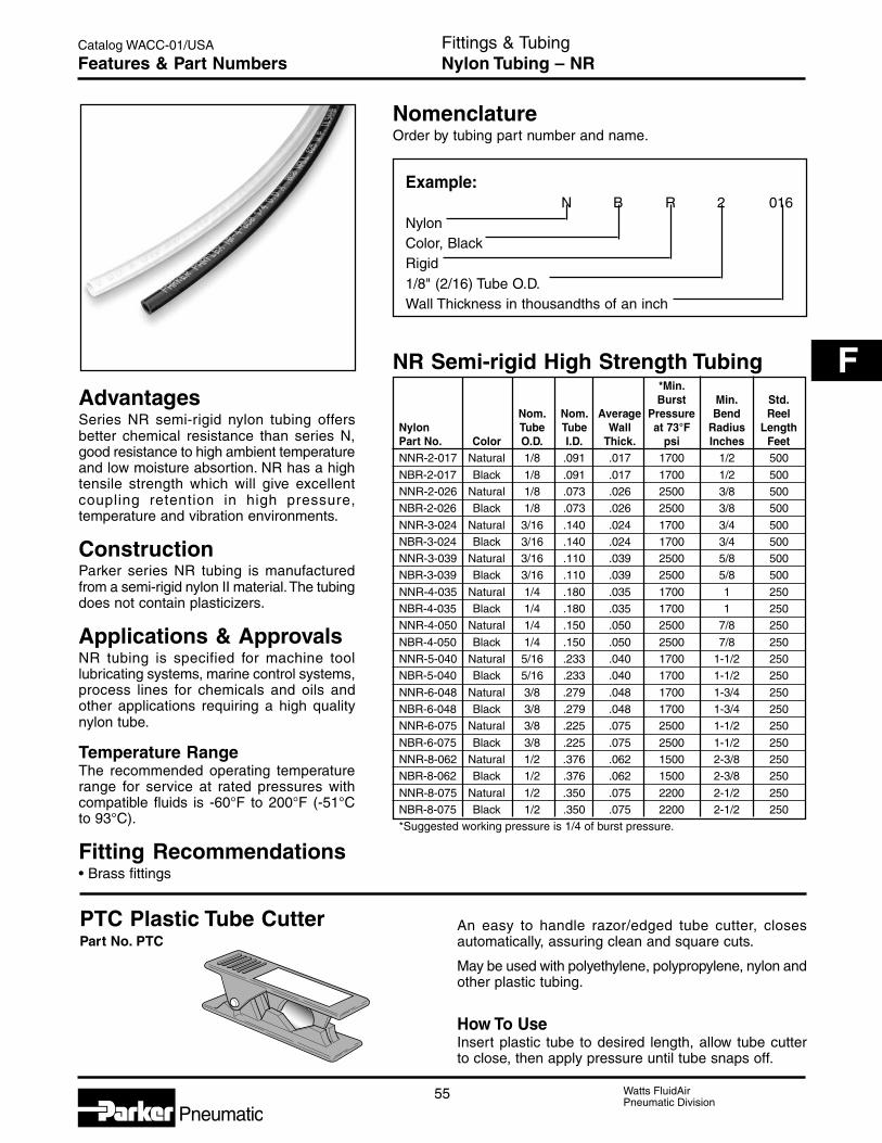
55 Watts FluidAirPneumatic Division
Catalog WACC-01/USA
F
Pneumatic
AdvantagesSeries NR semi-rigid nylon tubing offersbetter chemical resistance than series N,good resistance to high ambient temperatureand low moisture absortion. NR has a hightensile strength which will give excellentcoupling retention in high pressure,temperature and vibration environments.
ConstructionParker series NR tubing is manufacturedfrom a semi-rigid nylon II material. The tubingdoes not contain plasticizers.
Applications & ApprovalsNR tubing is specified for machine toollubricating systems, marine control systems,process lines for chemicals and oils andother applications requiring a high qualitynylon tube.
Temperature RangeThe recommended operating temperaturerange for service at rated pressures withcompatible fluids is -60°F to 200°F (-51°Cto 93°C).
Fitting Recommendations• Brass fittings
NomenclatureOrder by tubing part number and name.
Example:N B R 2 016
NylonColor, BlackRigid1/8" (2/16) Tube O.D.Wall Thickness in thousandths of an inch
NR Semi-rigid High Strength Tubing*Min.Burst Min. Std.
Nom. Nom. Average Pressure Bend ReelNylon Tube Tube Wall at 73°F Radius LengthPart No. Color O.D. I.D. Thick. psi Inches FeetNNR-2-017 Natural 1/8 .091 .017 1700 1/2 500
NBR-2-017 Black 1/8 .091 .017 1700 1/2 500NNR-2-026 Natural 1/8 .073 .026 2500 3/8 500NBR-2-026 Black 1/8 .073 .026 2500 3/8 500
NNR-3-024 Natural 3/16 .140 .024 1700 3/4 500NBR-3-024 Black 3/16 .140 .024 1700 3/4 500NNR-3-039 Natural 3/16 .110 .039 2500 5/8 500NBR-3-039 Black 3/16 .110 .039 2500 5/8 500
NNR-4-035 Natural 1/4 .180 .035 1700 1 250NBR-4-035 Black 1/4 .180 .035 1700 1 250NNR-4-050 Natural 1/4 .150 .050 2500 7/8 250
NBR-4-050 Black 1/4 .150 .050 2500 7/8 250NNR-5-040 Natural 5/16 .233 .040 1700 1-1/2 250NBR-5-040 Black 5/16 .233 .040 1700 1-1/2 250
NNR-6-048 Natural 3/8 .279 .048 1700 1-3/4 250NBR-6-048 Black 3/8 .279 .048 1700 1-3/4 250NNR-6-075 Natural 3/8 .225 .075 2500 1-1/2 250
NBR-6-075 Black 3/8 .225 .075 2500 1-1/2 250NNR-8-062 Natural 1/2 .376 .062 1500 2-3/8 250NBR-8-062 Black 1/2 .376 .062 1500 2-3/8 250
NNR-8-075 Natural 1/2 .350 .075 2200 2-1/2 250NBR-8-075 Black 1/2 .350 .075 2200 2-1/2 250*Suggested working pressure is 1/4 of burst pressure.
Fittings & TubingNylon Tubing – NRFeatures & Part Numbers
PTC Plastic Tube CutterPart No. PTC
An easy to handle razor/edged tube cutter, closesautomatically, assuring clean and square cuts.
May be used with polyethylene, polypropylene, nylon andother plastic tubing.
How To UseInsert plastic tube to desired length, allow tube cutterto close, then apply pressure until tube snaps off.

Watts FluidAirPneumatic Division
56
Catalog WACC-01/USA
Pneumatic
AdvantagesPolyurethane tubing is a high quality,precision-made tubing used in a wide rangeof demanding and critical applications.
Polyether based, polyurethane tubingoccupies a unique position among polymers,sharing the best properties of bothrubber and plastic. Urethane exhibits theelongation and recovery characteristics ofrubber and the chemical resistanceassociated with plastics. The tubing is tough,strong, kink-resistant and abrasion resistant,yet it’s flexible and easy to assemble ontodesignated fittings.
• Tough• Flexible• Broad Temperature Range• Eight Colors• Abrasion Resistant• Chemical Resistant
Applications & ApprovalsPolyurethane tubing is used for a widevariety of applications. Typical usageincludes air tools, robotics, pneumaticlogic and actuation systems, analyticalinstrumentation, vacuum equipment,pressure measurement apparatus,semi-conductor equipment manufacturersand a variety of medical and laboratoryapplications.
Temperature RangeSuggested operating temperatures, depending upon conditions are0°F to 200°F (-18°C to 93°C).
Fitting Recommendations• Thermoplastic fittings• Brass fittings
NomenclatureOrder by tubing part number and name.
Example:
U — 2 1 — BLK — 0250Polyurethane1/8" (2/16) Tube O.D.1/6" (1/16) Tube I.D.Color - BlackReel Length in feet
U Polyether Base TubingNom. Nom. Working** Burst ReelTube Tube Wall Pressure Pressure Length
Part No.* O.D. I.D. Thick. (PSI) (PSI) FeetU-21-0500
1/8 1/16 1/32 125 375500
U-21-0250 250U-42-0500
1/4 1/8 1/16 125 375500
U-42-0250 250U-64-0250
3/8 1/4 1/16 125 375250
U-64-0100 100 (coil)
U-86-02501/2 3/8 1/16 85 255
250U-86-0100 100 (coil)* Colors: Clear-Blank, Black-BLK, Green-GRN, Red-RED, Yellow-YEL,
Blue-BLU, Orange-ORG, Gray-GRA
** Based on a full 4:1 safety factor.
Fittings & TubingPolyurethane TubingFeatures & Part Numbers

57 Watts FluidAirPneumatic Division
Catalog WACC-01/USA
F
Pneumatic
MinimumBurstPressure(psig)
3.0 2.8 2.6 2.4 2.2 2.0 1.8 1.6 1.4 1.2 1.0 0.8 0.6 0.4 0.2 0.0
75 100 125 150 175 200
(NR-2-026)(NR-3-039)(NR-4-050)(NR-6-075)
(NR-8-075)
Temperature (deg. F.)
MinimumBurst Pressure(psig)(Thousands)
1.5 1.4 1.3 1.2 1.1 1.0 0.9 0.8 0.7 0.6 0.5 0.4 0.3 0.2 0.1 0.0
75 100 125 150 175 200
(N-4-040)
(N-2-016)(N-2.5-025)(N-3-025)(N-4-035)(N-5-040)(N-6-050)(N-8-062)
Temperature (deg. F.)
MinimumBurstPressure(psig)
2.0 1.9 1.8 1.7 1.6 1.5 1.4 1.3 1.2 1.1 1.0 0.9 0.8 0.7 0.6 0.5 0.4 0.3 0.2 0.1 0.0
75 100 125 150 175 200
(NR-2-017)(NR-3-024)(NR-4-035)(NR-5-040)(NR-6-048)
(NR-8-062)
Temperature (deg. F.)
MinimumBurst Pressure(psig)(Thousands)
Nylon Semi-Rigid TubingNR Series (NNR, NBR)1/8 thru 1/2 O.D. Inches
Nylon Flexible TubingN Series (NN, NB)1/8 thru 1/2 O.D. Inches
Nylon Semi-Rigid TubingNR Series (NNR, NBR)1/8 thru 1/2 O.D. Inches
2000
1800
1600
1400
1200
1000
800
600
400
200
0 75 100 125 150 175 200
Temperature (deg. F.)
Nylon Flexible TubingN Series1/8 thru 1/2 O.D. Inches
Suggested working pressures are 1/4 of burst pressure at system operating temperature.
(N-2-031)(N-3-046)(N-4-062)(N-6-093)(N-8-124)
Fittings & TubingBurst Pressure / Temperature ChartsTechnical Information

Watts FluidAirPneumatic Division
58
Catalog WACC-01/USA
Pneumatic
Fittings & TubingBurst Pressure / Temperature ChartsTechnical Information
350
300
250
200
150
100
50
0
(U-21) (U64)(U32) (U85)(U42) (U96)
(U128)
(U-86)
Temperature (deg. F.)
Polyethylene TubingLaboratory Grade E Series1/4 thru 5/8 O.D. Inches
900
800
700
600
500
400
300
200
100
(E-53)
(E-108)
Temperature (deg. F.)
MinimumBurstPressure(psig)
MinimumBurstPressure(psig)
MinimumBurstPressure(psig)
900
0
Temperature (deg. F.)
(E-86)
(E-64)
(E-43)
Polyurethane Tubing“U” Series Polyether Base4
1/8 thru 1/4 O.D. Inches
Polyethylene TubingFlame Resistant FRPE Series1/4 thru 5/8 O.D. INches
Suggested working pressure of polyethylene is 1/3 of burst pressure at system operating temperature.
800
700
600
500
400
300
200
100
75 100 125 150
75 100 125 150 75 100 125 150 175 180
(FRPE-2.5 x .030")(FRPE-6 x .062")
(FRPE-3 x .030")(FRPE-4 x .040")(FRPE-8 x .062")
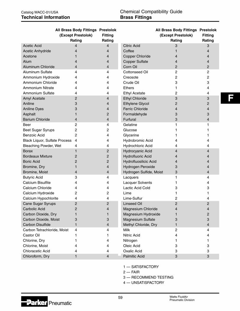
59 Watts FluidAirPneumatic Division
Catalog WACC-01/USA
F
Pneumatic
All Brass Body Fittings Prestolok(Except Prestolok) Fitting
Rating RatingAcetic Acid 4 4Acetic Anhydride 4 4Acetone 1 4Alum 4 4Aluminum Chloride 4 4Aluminum Sulfate 4 4Ammonium Hydroxide 4 4Ammonium Chloride 4 4Ammonium Nitrate 4 4Ammonium Sulfate 4 4Amyl Acetate 2 4Aniline 3 4Aniline Dyes 3 4Asphalt 1 2Barium Chloride 4 4Beer 2 4Beet Sugar Syrups 2 2Benzoic Acid 2 4Black Liquor, Sulfate Process 4 4Bleaching Powder, Wet 4 4Borax 1 2Bordeaux Mixture 2 2Boric Acid 2 2Bromine, Dry 1 4Bromine, Moist 4 4Butyric Acid 3 4Calcium Bisulfite 4 4Calcium Chloride 4 4Calcium Hydroxide 2 2Calcium Hypochlorite 4 4Cane Sugar Syrups 2 2Carbolic Acid 2 4Carbon Dioxide, Dry 1 1Carbon Dioxide, Moist 3 3Carbon Disulfide 1 4Carbon Tetrachloride, Moist 4 4Castor Oil 1 1Chlorine, Dry 1 4Chlorine, Moist 4 4Chloracetic Acid 4 4Chloroform, Dry 1 4
All Brass Body Fittings Prestolok(Except Prestolok) Fitting
Rating RatingCitric Acid 3 3Coffee 1 4Copper Chloride 4 4Copper Sulfate 4 4Corn Oil 2 2Cottonseed Oil 2 2Creosote 2 2Crude Oil 3 3Ethers 1 4Ethyl Acetate 2 4Ethyl Chloride 3 3Ethylene Glycol 2 2Ferric Chloride 4 4Formaldehyde 3 3Furfural 3 4Gelatine 1 1Glucose 1 1Glycerine 1 1Hydrobromic Acid 4 4Hydrochloric Acid 4 4Hydrocyanic Acid 4 4Hydrofluoric Acid 4 4Hydrofluosilicic Acid 4 4Hydrogen Peroxide 3 4Hydrogen Sulfide, Moist 3 4Lacquers 1 4Lacquer Solvents 1 4Lactic Acid Cold 3 3Lime 1 1Lime-Sulfur 2 4Linseed Oil 2 2Magnesium Chloride 4 4Magnesium Hydroxide 1 2Magnesium Sulfate 3 3Methyl Chloride, Dry 1 4Milk 2 4Nitric Acid 4 4Nitrogen 1 1Oleic Acid 3 3Oxalic Acid 3 3Palmitic Acid 3 3
1 — SATISFACTORY2 — FAIR3 — RECOMMEND TESTING4 — UNSATISFACTORY
Chemical Compatibility GuideBrass FittingsTechnical Information

Watts FluidAirPneumatic Division
60
Catalog WACC-01/USA
Pneumatic
All Brass Body Fittings Prestolok(Except Prestolok) Fitting
Rating Rating
Phosphoric Acid 4 4Potassium Chloride 4 4Potassium Cyanide 4 4Potassium Dichromate, Acid 4 4Potassium Hydroxide 3 3Potassium Sulfate 2 2Sea Water 3 3Soap Solutions 2 2Sodium Bicarbonate 3 3Sodium Bisulfate 4 4Sodium Bisulfite 4 4Sodium Carbonate 2 2Sodium Chloride 4 4Sodium Cyanide 4 4Sodium Hydroxide 3 3Sodium Hypochlorite 4 4Sodium Nitrate 3 3Sodium Peroxide 4 4Sodium Phosphate 2 2Sodium Silicate 2 2
All Brass Body Fittings Prestolok(Except Prestolok) Fitting
Rating Rating
Sodium Sulfite 4 4Sodium Thiosulfate 2 2Steam 3 4Stearic Acid 3 3Sulfur, Dry 1 4Sulfur Chloride, Dry 1 4Sulfur Dioxide, Dry 1 4Sulfur Dioxide, Moist 4 4Sulfur Trioxide, Dry 1 4Sulfuric Acid 4 4Sulfurous Acid 4 4Tar 2 2Tartaric Acid 3 3Toluene 1 4Trichloracetic Acid 4 4Trichlorethylene, Dry 1 3Trichlorethylene, Moist 3 3Vinegar 4 4Zinc Chloride 4 4Zinc Sulfate 4 4
Ratings Code1 — SATISFACTORY2 — FAIR3 — RECOMMEND TESTING4 — UNSATISFACTORY
This brass compatibility chart is a ready reference for brass fittings with various media. It is intended as a guide tochemical compatibility and has been compiled from the best available sources. Many factors (concentration,temperature, intermittent or continuous exposure, etc.) have a bearing upon the suitability of any material and,therefore, no guarantee, expressed or implied, is made to compatibility in any specific set of circumstances.
Chemical Compatibility GuideBrass FittingsTechnical Information

61 Watts FluidAirPneumatic Division
Catalog WACC-01/USA
F
Pneumatic
Chemical Compatibility GuideThermoplastic FittingsTechnical Information
PB PB, Mini-PBMedia Polyethylene Nylon Mini-PB
Acetaldehyde L L GAcetates G L GAcetic Acid G L GAcetic Anhydride G P GAcetone G L GAcetyl Bromide L L LAcetyl Chloride L L LAir G G GAlcohols G G GAluminum Salts G G GAmmonia G G GAmyl Acetate G L GAniline G L LAnimal Oils G G LArsenic Salts G G GAromatic Hydrocarbons L L LBarium Salts G G GBenzaldehyde L L LBenzene (Benzol) L L LBenzyl Alcohol G L LBleaching Liquors L L GBoric Acid Solutions G G GBromine L L LButane G P GButanol G G GButyl Acetate G G GCalcium Salts G G G
PB PB, Mini-PBMedia Polyethylene Nylon Mini-PB
Carbon Dioxide G G GCarbon Disulfide L L LCarbon Tetrachloride P L GCaustic Potash G G GCaustic Soda G G GChloracetic Acid G L LChlorine (Dry) L L LChlorine (Wet) L L LChlorobenzene L L LChloroform L L GChromic Acid L P LCopper Salts G G GCresol L L LCyclohexanone L L LEthers L L GEthyl Acetate G L GEthyl Alcohol G L GEthylamine G L LEthyl Bromide L L LEthyl Chloride L L LFatty Acids L G LFerric Salts G G GFormaldehyde G L GFormic Acid G L GFreon L L LGasoline G G L
Ratings Code
G — Good to excellent. Little or no swelling, tensile or surface changes. Preferred choice.L — Marginal or conditional. Noticeable effects but not necessarily indicating lack of serviceability. Further testing
suggested for specific application. Very long term effects such as stiffening or potential for crazing should beevaluated.
P — Poor or unsatisfactory. Not recommended without extensive and realistic testing.— — Not tested.

Watts FluidAirPneumatic Division
62
Catalog WACC-01/USA
Pneumatic
Chemical Compatibility GuideThermoplastic FittingsTechnical Information
PB PB, Mini-PB Mini-PBMedia Polyethylene NylonPolypropylene
Glucose G G GGlycerine G G GHydriodic Acid (Conc.) G P GHydrochloric Acid G L GHydrochloric Acid (Med. Conc.) G L GHydrofluoric Acid L P GHydrogen Peroxide (Conc.) G L LHydrogen Peroxide (Dil.) G L LHydrogen Sulfide G G GIodine G G GKerosene L G LKetones G G GLacquer Solvent L L LLactic Acid G G GLead Acetate G G GLinseed Oil G G GMagnesium Salts G G GNaphtha L G LNatural Gas L G LNickel Salts G G GNitric Acid (Conc.) L P LNitric Acid (Dil.) G L LNitrobenzene L L GNitrogen Oxides L L GNitrous Acid L L GOils (Animal and Mineral) L G L
PB PB, Mini-PB Mini-PBMedia Polyethylene NylonPolypropylene
Oils (Vegetable) L L LOxygen G G GPerchloric Acid G P LPhenol G P GPotassium Salts G G GPyridine L L LSilver Nitrate G G GSoap Solutions G G GSodium Salts G G GStearic Acid L G LSulfur Chloride L L LSulfuric Acid (Conc.) G P GSulfuric Acid (Dil.) G G GSulfurous Acid G L LTannic Acid G G GTanning Extracts G G GTitanium Salts G G GToluene (Toluol) L L LTrichloracetic Acid L P LTrichlorethylene L G LTurpentine L G LUrea G G GUric Acid G G GWater G G GXylene (Xylol) L L LZinc Chloride G G G
Ratings Code
G — Good to excellent. Little or no swelling, tensile or surface changes. Preferred choice.L — Marginal or conditional. Noticeable effects but not necessarily indicating lack of serviceability. Further testing suggested
for specific application. Very long term effects such as stiffening or potential for crazing should be evaluated.P — Poor or unsatisfactory. Not recommended without extensive and realistic testing.— — Not tested.

63 Watts FluidAirPneumatic Division
Catalog WACC-01/USA
F
Pneumatic
Chemical Compatibility GuideTubingTechnical Information
FRPEE Flame N NR
“E” Series Resistant Nylon Nylon UMedia Polyethylene Polyethylene “N” “NR” PolyurethaneAcetaldehyde L — L G LAcetates G — L G LAcetic Acid L — L G LAcetic Anhydride L — P L PAcetone G L L G PAcetyl Bromide L — L — —Acetyl Chloride L — L — —Air G G G G GAlcohols G G G G GAluminum Salts G G G G GAmmonia G L G G GAmyl Acetate G — L G LAniline L — L L PAnimal Oils L — G G GArsenic Salts G G G G GAromatic Hydrocarbons P P L G GBarium Salts G G G G GBenzaldehyde P P L G LBenzene (Benzol) P P L G LBenzyl Alcohol P P L L LBleaching Liquors G — L L LBoric Acid Solutions G G G G GBromine L — L P PButane L — P G PButanol G G G G GButyl Acetate G G G G LCalcium Salts G G G G GCarbon Dioxide G G G G GCarbon Disulfide L — L G LCarbon Tetrachloride P P L L LCaustic Potash G — G G GCaustic Soda G — G G GChloracetic Acid L — L L PChlorine (Dry) L — L P LChlorine (Wet) L — L P LChlorobenzene P P L L LChloroform P P L L LChromic Acid L — P P PCopper Salts G G G G GCresol P P L P PCyclohexanone L — L G PEthers L — L G LEthyl Acetate G — L G LEthyl Alcohol G G L G GEthylamine L — L L LEthyl Bromide P P L L —Ethyl Chloride P P L L —Fatty Acids L P G G GFerric Salts G — G G GFormaldehyde G — L G GFormic Acid L G L P PFreon L — L G LGasoline P P G G L
Ratings CodeG — Good to excellent. Little or no swelling, tensile or surface changes. Preferred choice.L — Marginal or conditional. Noticeable effects but not necessarily indicating lack of serviceability. Further testing suggested
for specific application. Very long term effects such as stiffening or potential for crazing should be evaluated.P — Poor or unsatisfactory. Not recommended without extensive and realistic testing.— — Not tested.

Watts FluidAirPneumatic Division
64
Catalog WACC-01/USA
Pneumatic
Chemical Compatibility GuideTubingTechnical Information
Ratings Code
G — Good to excellent. Little or no swelling, tensile or surface changes. Preferred choice.L — Marginal or conditional. Noticeable effects but not necessarily indicating lack of serviceability. Further testing suggested
for specific application. Very long term effects such as stiffening or potential for crazing should be evaluated.P — Poor or unsatisfactory. Not recommended without extensive and realistic testing.— — Not tested.
FRPEE Flame N NR
“E” Series Resistant Nylon Nylon UMedia Polyethylene Polyethylene “N” “NR” Polyurethane
Glucose G G G G GGlycerine G G G G GHydriodic Acid L — P L —Hydrochloric Acid (Conc.) L — L L LHydrochloric Acid (Med. Conc.) L — L G LHydrofluoric Acid L — P P PHydrogen Peroxide (Conc.) L — L G GHydrogen Peroxide (Dil.) L — L G GHydrogen Sulfide G — G G PIodine L — G G LKerosene L — G G GKetones G — G G PLacquer Solvent L — L L —Lactic Acid G — G G GLead Acetate G — G G GLinseed Oil L — G G GMagnesium Salts G — G G GNaphtha L G G G GNatural Gas L — G G GNickel Salts G — G G GNitric Acid (Conc.) P G P P PNitric Acid (Dil.) P P L L PNitrobenzene P P L L PNitrogen Oxides L — L L —Nitrous Acid L — L L LOils (Animal and Mineral) L — G G GOils (Vegetable) L — L G GOxygen G G G G GPerchloric Acid P P P P PPhenol P P P P PPotassium Salts G G G G GPyridine L — L L PSilver Nitrate G G G G GSoap Solutions G G G G GSodium Salts G G G G GStearic Acid L — G G LSulfur Chloride L — L L —Sulfuric Acid (Conc.) P P P P PSulfuric Acid (Dil.) P P G L LSulfurous Acid P P L L LTannic Acid G — G G PTanning Extracts G — G G PTitanium Salts G G G G GToluene (Toluol) P P L G LTrichloracetic Acid L — P P PTrichlorethylene P P G L PTurpentine L — G G GUrea G — G G GUric Acid G — G G GWater G G G G GXylene (Xylol) P P L G GZinc Chloride G — G G G

65 Watts FluidAirPneumatic Division
Catalog WACC-01/USA
F
Pneumatic
Chemical Compatibility GuideFootnotes & ApprovalsTechnical Information
Products-Government & Agency Approvals
Agency and ApprovedSpecifications Products
Flame Resistance:UL94V-2 Tubing: FRPE
Dry Food Contact: Tubing: E,FDA, CFR21 Part 177. Fittings: PB (Nylon & Polyethylene)
Potable Water, Liquid Foods: Tubing: N, P, UNSF Std. 14, 42, 53 Fittings: PB (Nylon & Polyethylene)NSF Std. 51

Watts FluidAirPneumatic Division
66
Catalog WACC-01/USA
Pneumatic
! DANGER: Failure or improper selection or improper use of hose, fittings, or related accessories can cause death, personal injury and propertydamage.
Possible consequences of failure or improper selection or improper use of hose, fittings or related accessories include but are not limited to:
• Fittings thrown off at high speed. • Dangerously whipping hose.• High velocity fluid discharge. • Contact with conveyed fluids that may be hot, cold, toxic• Explosion or burning of the conveyed fluid. or otherwise injurious.• Electrocution from high voltage electric power lines or other • Sparking or explosion caused by static electricity buildup.
sources of electricity. • Sparking or explosion while paint or flammable liquid• Contact with suddenly moving or falling objects that are to spraying.
be held in position or moved by the conveyed fluid.
Before selecting or using any hose or fittings or related accessories, it is important that you read and follow the instructions in the Guide below.
1.0 GENERAL INSTRUCTIONS
1.1 Scope: This guide provides instructions for selecting and using(including assembling, installing, and maintaining) hose (includingall rubber and/or plastic products commonly called “hose” or“tubing”), fittings (including all products commonly called “fittings” or“couplings” for attachment to hose), and related accessories(including crimping and swaging machines and tooling). This guideis a supplement to and is to be used with, the specific publicationsfor the specific hose, fittings and related accessories that are beingconsidered for use.
1.2 Fail-Safe: Hose and hose assemblies can and do fall withoutwarning for many reasons. Design all systems and equipment in afail-safe mode, so that failure of the hose or hose assembly will notendanger persons or property.
1.3 Distribution: Provide a copy of this guide to each person that isresponsible for selecting or using hose and fitting products. Do notselect or use hose and fittings without thoroughly reading andunderstanding this guide as well as the specific publications for theproducts considered or selected.
1.4 User Responsibility: Due to the wide variety of operatingconditions and uses for hose and fittings, the manufacturer and itsdistributors do not represent or warrant that any particular hose orfitting is suitable for any specific and use system. This guide doesnot analyze all technical parameters that must be considered inselecting a product. The user, through their own analysis andtesting, are solely responsible for:• Making the final selection of the hose and fitting.• Assuring that the user’s requirements are met and that
the use presents no health or safety hazards.• Providing all appropriate health and safety warnings on
the equipment on which the hose and fittings are used.
1.5 Additional Questions: Consult the supplier if you have anyadditional questions or require additional information.
2.0 HOSE AND FITTING SELECTION INSTRUCTIONS
2.1 Electrical Conductivity: Certain applications require that a hosebe nonconductive to prevent electrical current flow. Otherapplications require the hose to be sufficiently conductive to drainoff static electricity. Extreme care must be exercised when selectinghose and fittings for these or any other applications in whichelectrical conductivity or nonconductivity is a factor.
For applications that require hose to be electrically nonconductive,including but not limited to applications near high voltage electriclines, only special nonconductive hose can be used. Themanufacturer of the equipment in which the nonconductive hose isto be used must be consulted to be certain that the hose andfittings that are selected are proper for the application. Do not useany hose or fitting for any such application requiring nonconductivehose, including but not limited to applications near high voltageelectric lines, unless (I) the application is expressly approved in thetechnical publication for the product, (II) the hose is both orangecolor and marked “nonconductive”, and (III) the manufacturer of theequipment on which the hose is to be used specifically approvesthe particular hose and fitting for such use.
The manufacturer does not supply any hose or fittings forconveying paint in airless paint spraying or similar applications, and
hose and fittings must not be so used. A special hose and fittingassembly is required for this application, to avoid static electricitybuildup. If the proper hose and fitting assembly is not used for thisapplication, static electricity can build up and cause a spark thatmay result in an explosion and/or fire.
The electrical conductivity or nonconductivity of hose and fittings isdependent upon many factors and may be susceptible to change.These factors include but are not limited to the various materialsused to make the hose and the fittings, manufacturing methods(including moisture control), how the fittings contact the hose, ageand amount of deterioration or damage or other changes, moisturecontent of the hose at any particular time, and other factors.
2.2 Pressure: Hose selection must be made so that the publishedmaximum recommended working pressure of the hose is equal toor greater than the maximum system pressure. Surge pressures inthe system higher than the published maximum recommendedworking pressure will cause failure or shorten hose life. Do notconfuse burst pressure or other pressure values with workingpressure and do not use burst pressure or other pressure valuesfor this purpose.
2.3 Suction: Hoses used for suction applications must be selected toensure that the hose will withstand the vacuum and pressure of thesystem. Improperly selected hose may collapse in suctionapplication.
2.4 Temperature: Be certain that fluid and ambient temperatures, bothsteady and transient, do not exceed the limitations of the hose.Care must be taken when routing hose near hot objects such asmanifolds.
2.5 Fluid Compatibility: Hose selection must assure compatibility ofthe hose tube, cover, reinforcement, and fittings with the fluidmedia used. See the fluid compatibility chart in the publication forthe product being considered or used.
2.6 Permeation: Permeation (that is, seepage through the hose) willoccur from inside the hose to outside when hose is used withgases, liquid and gas fuels, and refrigerants (including but notlimited to such materials as helium, fuel, oil, natural gas, or freon).This permeation may result in high concentrations of vapors whichare potentially flammable, explosive, or toxic, and in loss of fluid.Dangerous explosions, fires, and other hazards can result whenusing the wrong hose for such applications. The system designermust take into account the fact that this permeation will take placeand must not use hose if this permeation could be hazardous. Thesystem designer must take into account all legal, government,insurance, or any other special regulations which govern the use offuels and refrigerants. Never use a hose even though the fluidcompatibility is acceptable without considering the potentialhazardous effects that can result from permeation through thehose assembly.
Permeation of moisture from outside the hose to inside the hosewill also occur in hose assemblies, regardless of internal pressure.If this moisture permeation would have detrimental effects(particularly but not limited to refrigeration and air conditioningsystems), incorporation of sufficient drying capacity in the systemor other appropriate system safeguards should be selected andused.
Fittings & TubingGeneral Selection InformationTechnical Information

67 Watts FluidAirPneumatic Division
Catalog WACC-01/USA
F
Pneumatic
2.7 Size: Transmission of power by means of pressurized fluid varieswith pressure and rate of flow. The size of the components mustbe adequate to keep pressure losses to a minimum and avoiddamage due to heat generation or excessive fluid velocity.
2.8 Routing: Attention must be given to optimum routing to minimizeinherent problems (kinking or flow restriction due to hosecollapse). Freon® is a registered trademark of the E.l. DuPont DeNemours Co., Inc.
2.9 Environment: Care must be taken to ensure that the hose andfittings are either compatible with or protected from theenvironment (that is, surrounding conditions) to which they areexposed. Environmental conditions include but are not limited tooultraviolet radiation, sunlight, heat, ozone, moisture, water, saltwater, chemicals, and air pollutants that can cause degradationand premature failure.
2.10 Mechanical Loads: External forces can significantly reducehose life or cause failure. Mechanical loads which must beconsidered include excessive flexing, twist, kinking, tensile orside loads, bend radius, and vibration. Use of swivel type fittingsor adapters may be required to ensure no twist is put into thehose. Applications must be tested prior to hose selection.
2.11 Physical Damage: Care must be taken to protect hose from wear,snagging and cutting, which can cause premature hose failure.
2.13 Length: When establishing a proper hose length, motionabsorption, hose length changes due to pressure, and hose andmachine tolerances must be considered.
2.14 Specifications and Standards: When selecting hose and fittings,government, industry, and manufacturer specifications andrecommendations must be reviewed and followed as applicable.
2.15 Hose Cleanliness: Hose components may vary in cleanlinesslevels. Care must be taken to ensure that the assembly selectedhas an adequate level of cleanliness for the application.
2.16 Fire Resistant Fluids: Some fire resistant fluids require thesame hose as petroleum oil. Some use a special hose, while afew fluids will not work with any hose at all. See instructions 2.5and 1.5. The wrong hose may fail after a very short service. Inaddition, all liquids may burn fiercely under certain conditions,and leakage may be hazardous.
2.17 Radiant Heat: Hose can be heated to destruction withoutcontact, by such nearby items as hot manifolds or molten metal.The same heat source may then initiate a fire. This can occurdespite the presence of cool air around the hose.
2.18 Welding and Brazing: Heating of plated parts, including hosefittings and adapters, above 450°F (232°C) such as duringwelding, brazing, or soldering may emit deadly gases.
2.19 Radiation: Radiation affects all materials used in hoseassemblies. Since the long term effects may be unknown, do notexpose hose assemblies to radiation.
3.0 HOSE AND FITTING ASSEMBLY ANDINSTALLATION INSTRUCTIONS
3.1 Pre-lnstallatlon Inspection: Prior to installation, a carefulexamination of the hose must be performed. All components mustbe checked for correct style, size, catalog number, and length. Inaddition, the hose must be examined for cleanliness, obstructions,blisters, cover looseness, or any other viable detects.
3.2 Hose and Fitting Assembly: Do not assemble fittings onto a hosethat is not specifically listed by the manufacturer for that fittingunless authorized in writing by the chief engineer. Do not assembleone manufacturer’s fitting on another manufacturer’s hose.
The published instructions must be followed for assemblingfittings on the hose. These instructions are provided in the fittingcatalog for the specific fitting being used.
3.3 Related Accessories: Do not crimp or swage any hose orfitting with anything but the proper listed swage or crimpmachine, and dies, and in accordance with publishedinstructions. Do not crimp or swage one manufacturer’s hosefitting with another’s crimp or swage die unless authorized inwriting by their chief engineer.
3.4 Parts: Do not use any hose fitting part (including but not limitedto socket, shell, nipple, or insert) except with the correct matingparts, in accordance with instructions, unless authorized inwriting by the chief engineer of the appropriate manufacturer.
3.5 Reusable/Permanent: Do not reuse any reusable hose productthat has blown or pulled off a hose. Do not reuse a permanent(that is, crimped or swaged) hose fitting or any part thereof.
3.6 Minimum Bend Radius: Installation of a hose at less than theminimum listed bend radius may significantly reduce the hoselife. Particular attention must be given to preclude sharp bendingat the hose/fitting juncture.
3.7 Twist Angle and Orientation: Hose installations must be such thatrelative motion of machine components does not produce twisting.
3.8 Securement: In many applications, it may be necessary torestrain, protect, or guide the hose to protect it from damage byunnecessary flexing, pressure surges, and contact with othermechanical components. Care must be taken to ensure suchrestraints do not introduce additional stress or wear points.
3.9 Proper Connection of Ports: Proper physical installation of thehose requires a correctly installed port connection whileensuring that no twist or torque is transferred to the hose.
3.10 External Damage: Proper installation is not complete withoutensuring that tensile loads, side loads, kinking, flattening,potential abrasion, thread damage, or damage to sealingsurfaces are corrected or eliminated. See instruction 2.10.
3.11 System Checkout: All air entrapment in hydraulic lines must beeliminated, all systems must be pressurized to the maximumsystem pressure and checked for proper function and freedomfrom leaks. Personnel must stay out of potential hazardousareas while testing and using.
4.0 HOSE AND FITTING MAINTENANCE INSTRUCTIONS
4.1 Visual Inspection Hose/Fitting: Any of the following conditionsrequire immediate shut down and replacement of the hoseassembly• Fitting slippage on hose.• Damaged, cut or abraded cover (any reinforcement exposed).• Hard, stiff, heat cracked, or charred hose.• Cracked, damaged, or badly corroded fittings.• Leaks at fitting or in hose.• Kinked, crushed, flattened or twisted hose.• Blistered, soft, degraded, or loose cover.
4.2 Visual Inspection All Other: The following items must betightened, repaired or replaced as required:• Leaking port conditions.• Remove excess dirt buildup.• Clamps, guards, shields.• System fluid level, fluid type and any air entrapment.
4.3 Functional Test: Operate the system at maximum operatingpressure and check for possible malfunctions and freedom fromleaks. Personnel must avoid potential hazardous areas whiletesting and using.
4.4 Replacement Intervals: Specific replacement intervals must beconsidered based on previous service life, government or industryrecommendations, or when failure could result in unacceptabledowntime, damage, or injury risk. See instructions 1.2.
Fittings & TubingGeneral Selection InformationTechnical Information

Watts FluidAirPneumatic Division
68
Catalog WACC-01/USA
Pneumatic
Fittings & TubingNotes

Watts FluidAirPneumatic Division
Pneumatic
G
AirlineAccessories
Section G
Pneumatic
Tank Valves & Air Chucks .......................................... 2
Miniature Lubricator .................................................... 3
Rotating Pressure Joints ............................................ 4
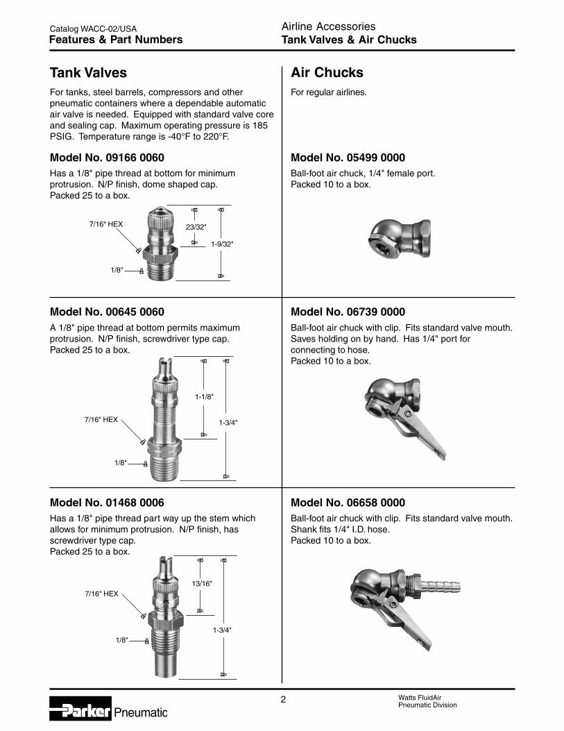
Watts FluidAirPneumatic Division
Pneumatic2
Catalog WACC-02/USA
For tanks, steel barrels, compressors and otherpneumatic containers where a dependable automaticair valve is needed. Equipped with standard valve coreand sealing cap. Maximum operating pressure is 185PSIG. Temperature range is -40°F to 220°F.
Tank Valves Air ChucksFor regular airlines.
Model No. 01468 0006Has a 1/8" pipe thread part way up the stem whichallows for minimum protrusion. N/P finish, hasscrewdriver type cap.Packed 25 to a box.
Model No. 00645 0060A 1/8" pipe thread at bottom permits maximumprotrusion. N/P finish, screwdriver type cap.Packed 25 to a box.
Model No. 05499 0000Ball-foot air chuck, 1/4" female port.Packed 10 to a box.
Model No. 09166 0060Has a 1/8" pipe thread at bottom for minimumprotrusion. N/P finish, dome shaped cap.Packed 25 to a box.
Model No. 06658 0000Ball-foot air chuck with clip. Fits standard valve mouth.Shank fits 1/4" I.D. hose.Packed 10 to a box.
Model No. 06739 0000Ball-foot air chuck with clip. Fits standard valve mouth.Saves holding on by hand. Has 1/4" port forconnecting to hose.Packed 10 to a box.
ä
ä
1-3/4"7/16" HEX
1/8"
ä
ä
ä
1/8"
13/16"
ä
ä
äää ä
1-9/32"
23/32"
ä
ä
ä
7/16" HEX
ä1/8"
ä
ä ä
1-1/8"
1-3/4"
7/16" HEX
Airline AccessoriesTank Valves & Air ChucksFeatures & Part Numbers

3 Watts FluidAirPneumatic Division
Pneumatic
Catalog WACC-02/USA
G
Features & Part Numbers
ApplicationThe 02L lubricator is recommended to be directlyattached to the air tool inlet or air appliance. Theselubricators allow air tools to operate at full efficiencyby preventing sticking, extending service life. Effectivetool lubrication saves money by reducing equipmentdown time.
OperationWhen the fill cap (A) is removed, turn oil adjustmentscrew (B) (counterclockwise for more oil, clockwise forless oil) 1/4 turn at a time to set oil adjustment to userrequirements. Connect to air tool. Cycle air tool a fewseconds to allow oil adjustment to become apparent.Automatic lubrication of the air occurs upon passage ofthe rated air flow when the tool is triggered.
Port Size Model Number1/4" 02L1A3/8" 02L2A
Fill Cap (A)
Oil Adj. Screw (B)
NPT Port(Full Swivel)
NPTPort
FLOW1.25Hex
1.42
1.92
2.16
2.66
Airline AccessoriesMiniature Lubricator
Miniature Lubricator
Features• Extends the service life of air
operated hand tools.
• Reduces downtime of air operatedequipment, saves money.
• Small / lightweight.
• Automatic lubrication with airtool operation.
• Adjustable oil flow.
• Corrosion resistant.
• Full swivel outlet port.
02L SpecificationsOil Capacity9 ccFlow .................. 32 SCFM At 90 PSIG inlet & 5 PSI pressure dropPort Threads –Inlet - Stationary 1/4" & 3/8"
Outlet - Full Swivel 1/4" & 3/8"
Pressure &Temperature Rating – ..................... 0 to 250 PSIG (0 to 17.2 bar)
32°F to 125°F (0°C to 52°C)
Suggested Lubricant ........................................................ F442 OilPetroleum based oil of 100 to 200 SSU viscosityat 100°F and an aniline point greater than 200°F(DO NOT USE OILS WITH ADDITIVES,COMPOUNDED OILS CONTAINING SOLVENTS,GRAPHITE, DETERGENTS, OR SYNTHETIC OILS.)
02L Materials of ConstructionBody ....................................................... Hard Anodized AluminumInsertNylonNut .........................................................................Cad. Plated SteelSeals ....................................................................................... Nitrile
Ordering Information

Watts FluidAirPneumatic Division
Pneumatic4
Catalog WACC-02/USA
A1 B1 C1 D1 E1
Part Ball RetainingNumber Rotor Retainer Packing Bearing Ring
00831 0019B 00831 0020 00831 0040 00831 0050 00831 0060 05100 603900832 0019B 00832 0020 00832 0040 00832 0049 00832 0060 05100 605900834 0019B 00834 0012 00834 0014 00834 0015 00834 0016 05100 6078
F1 G1 H1 J1 K1
Part Rotor Seal “O”Number Assembly Ring Ring Spring Ring
00831 0019B 00831 0080 00831 0030 03718 0012 00831 0070 03327 005000832 0019B 00832 0018 00832 0009 03718 0032 00832 0070 03327 008000834 0019B 00834 0018 00834 0013 03718 0036 00834 0017 03327 0100
Part Dimensions in InchesNumber A B C D F G
00831 0019B 2.62 .90 1.37 .75 5/8 5/800832 0019B 3.19 1.12 1.62 1.00 7/8 7/800834 0019B 4.00 1.38 2.13 1.25 1-1/16 1-1/16
Replacement Parts
ApplicationDesigned for compressed air or hydraulic service,rotating joints provide long, trouble-free service. Theyoperate at pressures to 140 PSIG and speeds up to1000 RPM.
FeaturesPressure tight connections between a fixed and arotating member make it possible to transmit fluidsthough axles, shafts, indexing tables, etc.
Ball bearings minimize rotating friction, assuring longlife.
Airline AccessoriesRotating Pressure JointsFeatures & Part Numbers
Part Port Port Air Operating Flow CapacityNumber X Y Pressure (SCFM)*
00831 0019B 1/8" 1/8" Up to 400 PSIG 2000832 0019B 1/4" 1/4" Up to 300 PSIG 9000834 0019B 1/2" 1/2" Up to 150 PSIG 285
Ordering & DimensionalInformation
C
A
B
D
Hex. G
Thread Y
Thread X
F(Across Flats)

Watts FluidAirPneumatic Division
Pneumatic
H
Section H
Part Number / Page Index .......................................... 2Industrial Interchange Nipples ................................. 3-4Sleevmatic Couplers ............................................... 5-7Saflomatic Couplers .............................................. 8-10Twist-Lock Quick Connect Couplings .................. 11-13Economatic Quick Connect Couplings ................ 14-15
Quick Couplingsand Adapters

Watts FluidAirPneumatic Division
Pneumatic2
Catalog WACC-01/USA
Part Number Page16 ........................................................ 617 ........................................................ 624 ........................................................ 625 ........................................................ 614K ...................................................... 714K .................................................... 1014KY ................................................... 714KY ................................................. 1016-5B ................................................... 716-5BP ................................................ 716-6B ................................................... 716-6BP ................................................ 716-7B ................................................... 716E ...................................................... 616G ..................................................... 616K ...................................................... 716K .................................................... 1016KY ................................................... 716KY ................................................. 1017E ...................................................... 617G ..................................................... 621K ...................................................... 721K2 .................................................. 1021KY ................................................... 721KY ................................................. 1024-5B ................................................... 724-5BP ................................................ 724-6B ................................................... 724C ...................................................... 624F ...................................................... 625C ...................................................... 625F ...................................................... 638K .................................................... 1038KY ................................................. 10A2C ................................................... 15A2C E ................................................ 15A3C ................................................... 15A3C E ................................................ 15A8C ................................................... 15A8CP ................................................. 15B20-3B ................................................ 7B20-3BP .............................................. 7B20-4B ................................................ 7B20-5B ................................................ 7B20-5BP .............................................. 7B22 ...................................................... 6B22A ................................................... 6B22-C3 ................................................ 6B22-C5 ................................................ 6B22-C6 ................................................ 6B22E ................................................... 6B23 ...................................................... 6B23A ................................................... 6B23E ................................................... 6B30-3B .............................................. 10B30-3BP ............................................ 10
B30-4B .............................................. 10B30-5B .............................................. 10B30-5BP ............................................ 10B32 ...................................................... 9B32A ................................................... 9B32E ................................................... 9B33 ...................................................... 9B33A ................................................... 9B33E ................................................... 9B34 ...................................................... 9B34-5B .............................................. 10B34-5BP ............................................ 10B34-6B .............................................. 10B34C ................................................... 9B34F .................................................... 9B35 ...................................................... 9B35C ................................................... 9B35F .................................................... 9B36 ...................................................... 9B36-6B .............................................. 10B36-6BP ............................................ 10B36-7B .............................................. 10B36E ................................................... 9B36G ................................................... 9B37 ...................................................... 9B37E ................................................... 9B37G ................................................... 9B38 ...................................................... 9B38-6B .............................................. 10B38-7B .............................................. 10B38-8B .............................................. 10B38F .................................................... 9B38J .................................................... 9B39 ...................................................... 9B39F .................................................... 9B39J .................................................... 9B50-3BP ............................................ 14B50-5BP ............................................ 14B52 .................................................... 14B52E ................................................. 14B53 .................................................... 14B53E ................................................. 14H00E ................................................... 3H0C ..................................................... 3H0E ..................................................... 3H0F ..................................................... 3H1C ..................................................... 3H1E ..................................................... 3H1F ..................................................... 3H2C ..................................................... 3H2C-E ................................................. 3H2E ..................................................... 3H2E-F .................................................. 3H2F ..................................................... 3H2F-G ................................................. 3H2G ..................................................... 3
H2G-F ................................................. 3H2G-J .................................................. 3H3C ..................................................... 3H3C-E ................................................. 3H3E ..................................................... 3H3E-F .................................................. 3H3F ..................................................... 3H3F-G ................................................. 3H3G ..................................................... 3H3G-F ................................................. 3H3G-J .................................................. 3H4EP ................................................... 4H4F ..................................................... 4H4FP ................................................... 4H5E ..................................................... 4H5EP ................................................... 4H5F ..................................................... 4H5F-G ................................................. 4H5FP ................................................... 4H5G ..................................................... 4H5G-F ................................................. 4H5G-J .................................................. 4H6E ..................................................... 4H6EP ................................................... 4H8C ..................................................... 4H8C-C3 ............................................... 4H8C-C5 ............................................... 4H8C-C6 ............................................... 4H8C-D ................................................. 4H8CP ................................................... 4H9C ..................................................... 4H9CP ................................................... 4TL-251-4FP ....................................... 12TL-251-4MP ...................................... 12TL-251-6MP ...................................... 12TL-254-2FP ....................................... 12TL-254-2MP ...................................... 12TL-254-4FP ....................................... 12TL-254-4HB ....................................... 12TL-254-4MP ...................................... 12TL-254-6HB ....................................... 12TL-501-12FP ..................................... 13TL-501-4FP ....................................... 13TL-501-6FP ....................................... 13TL-501-6MP ...................................... 13TL-501-8FP ....................................... 13TL-501-8MP ...................................... 13TL-504-12MP..................................... 13TL-504-4FP ....................................... 13TL-504-4HB ....................................... 13TL-504-4MP ...................................... 13TL-504-6FP ....................................... 13TL-504-6HB ....................................... 13TL-504-6MP ...................................... 13TL-504-8HB ....................................... 13TL-504-8MP ...................................... 13
Quick Couplings and AdaptersPart Number / Page IndexIndex
Part Number Page Part Number Page
(Revised 07/07/05)
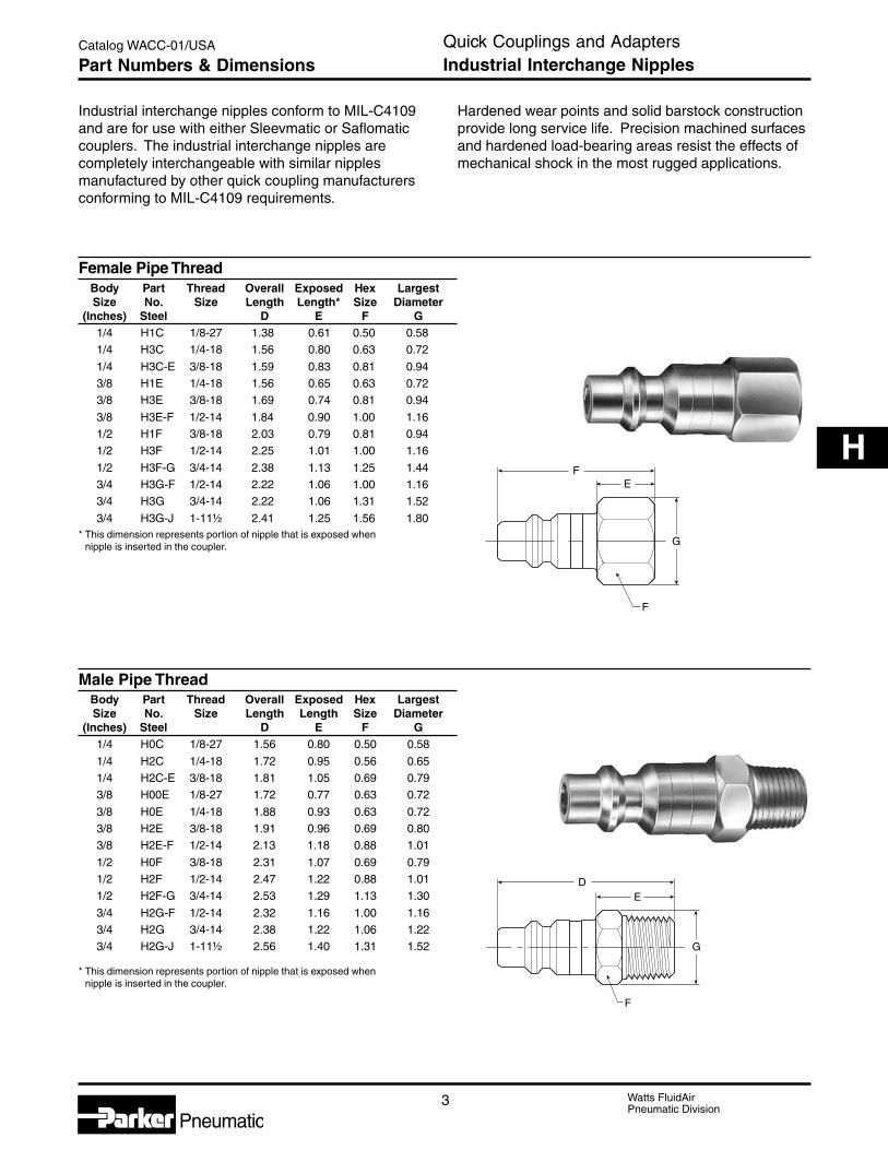
3 Watts FluidAirPneumatic Division
Pneumatic
Catalog WACC-01/USA
H
DE
G
F
G
EF
F
Industrial interchange nipples conform to MIL-C4109and are for use with either Sleevmatic or Saflomaticcouplers. The industrial interchange nipples arecompletely interchangeable with similar nipplesmanufactured by other quick coupling manufacturersconforming to MIL-C4109 requirements.
Hardened wear points and solid barstock constructionprovide long service life. Precision machined surfacesand hardened load-bearing areas resist the effects ofmechanical shock in the most rugged applications.
Female Pipe ThreadBody Part Thread Overall Exposed Hex LargestSize No. Size Length Length* Size Diameter
(Inches) Steel D E F G1/4 H1C 1/8-27 1.38 0.61 0.50 0.581/4 H3C 1/4-18 1.56 0.80 0.63 0.72
1/4 H3C-E 3/8-18 1.59 0.83 0.81 0.943/8 H1E 1/4-18 1.56 0.65 0.63 0.723/8 H3E 3/8-18 1.69 0.74 0.81 0.94
3/8 H3E-F 1/2-14 1.84 0.90 1.00 1.161/2 H1F 3/8-18 2.03 0.79 0.81 0.941/2 H3F 1/2-14 2.25 1.01 1.00 1.16
1/2 H3F-G 3/4-14 2.38 1.13 1.25 1.443/4 H3G-F 1/2-14 2.22 1.06 1.00 1.163/4 H3G 3/4-14 2.22 1.06 1.31 1.52
3/4 H3G-J 1-11½ 2.41 1.25 1.56 1.80* This dimension represents portion of nipple that is exposed when
nipple is inserted in the coupler.
Male Pipe ThreadBody Part Thread Overall Exposed Hex LargestSize No. Size Length Length Size Diameter
(Inches) Steel D E F G1/4 H0C 1/8-27 1.56 0.80 0.50 0.58
1/4 H2C 1/4-18 1.72 0.95 0.56 0.651/4 H2C-E 3/8-18 1.81 1.05 0.69 0.793/8 H00E 1/8-27 1.72 0.77 0.63 0.72
3/8 H0E 1/4-18 1.88 0.93 0.63 0.723/8 H2E 3/8-18 1.91 0.96 0.69 0.803/8 H2E-F 1/2-14 2.13 1.18 0.88 1.01
1/2 H0F 3/8-18 2.31 1.07 0.69 0.791/2 H2F 1/2-14 2.47 1.22 0.88 1.011/2 H2F-G 3/4-14 2.53 1.29 1.13 1.30
3/4 H2G-F 1/2-14 2.32 1.16 1.00 1.163/4 H2G 3/4-14 2.38 1.22 1.06 1.223/4 H2G-J 1-11½ 2.56 1.40 1.31 1.52
* This dimension represents portion of nipple that is exposed whennipple is inserted in the coupler.
Quick Couplings and AdaptersIndustrial Interchange NipplesPart Numbers & Dimensions
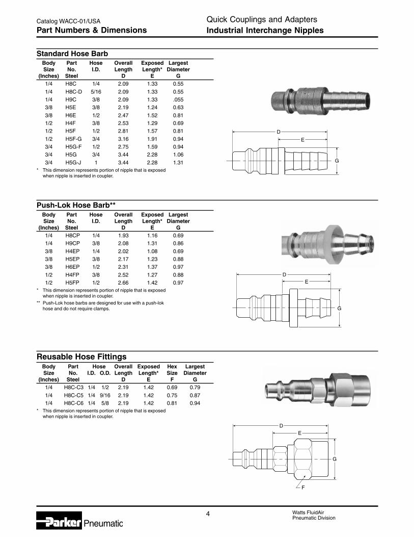
Watts FluidAirPneumatic Division
Pneumatic4
Catalog WACC-01/USA
DE
G
D
E
G
Standard Hose BarbBody Part Hose Overall Exposed LargestSize No. I.D. Length Length* Diameter
(Inches) Steel D E G1/4 H8C 1/4 2.09 1.33 0.55
1/4 H8C-D 5/16 2.09 1.33 0.551/4 H9C 3/8 2.09 1.33 .0553/8 H5E 3/8 2.19 1.24 0.63
3/8 H6E 1/2 2.47 1.52 0.811/2 H4F 3/8 2.53 1.29 0.691/2 H5F 1/2 2.81 1.57 0.81
1/2 H5F-G 3/4 3.16 1.91 0.943/4 H5G-F 1/2 2.75 1.59 0.943/4 H5G 3/4 3.44 2.28 1.06
3/4 H5G-J 1 3.44 2.28 1.31* This dimension represents portion of nipple that is exposed
when nipple is inserted in coupler.
Push-Lok Hose Barb**Body Part Hose Overall Exposed LargestSize No. I.D. Length Length* Diameter
(Inches) Steel D E G1/4 H8CP 1/4 1.93 1.16 0.691/4 H9CP 3/8 2.08 1.31 0.86
3/8 H4EP 1/4 2.02 1.08 0.693/8 H5EP 3/8 2.17 1.23 0.883/8 H6EP 1/2 2.31 1.37 0.97
1/2 H4FP 3/8 2.52 1.27 0.881/2 H5FP 1/2 2.66 1.42 0.97
* This dimension represents portion of nipple that is exposedwhen nipple is inserted in coupler.
** Push-Lok hose barbs are designed for use with a push-lokhose and do not require clamps.
Reusable Hose FittingsBody Part Hose Overall Exposed Hex LargestSize No. I.D. O.D. Length Length* Size Diameter
(Inches) Steel D E F G1/4 H8C-C3 1/4 1/2 2.19 1.42 0.69 0.79
1/4 H8C-C5 1/4 9/16 2.19 1.42 0.75 0.871/4 H8C-C6 1/4 5/8 2.19 1.42 0.81 0.94
* This dimension represents portion of nipple that is exposedwhen nipple is inserted in coupler.
DE
F
G
Quick Couplings and AdaptersIndustrial Interchange NipplesPart Numbers & Dimensions

5 Watts FluidAirPneumatic Division
Pneumatic
Catalog WACC-01/USA
H
OperationSleeve type couplings are widely used to connect airand low-pressure fluid hose lines.Their compact and economical design uses a balllocking mechanism consisting of captive steel ballsthat engage the locking groove on the mating nipple.As pictured, the sliding spring loaded sleeve on thecoupler must be manually retracted in order to connector disconnect the nipple. It is easy to do, but twohands are normally required.Common applications include compressed air, water,grease, paint, limited vacuum and limited gases.
Features1. Hardened wear points and solid barstock
construction provide long life for these qualitycouplings. Precision machined surfaces resist theeffects of mechanical shocks, even in rugged use.
2. Tubular valve with large flow passages delivers highair flows with minimal pressure drop for efficientperformance.
3. Molded seals with high quality valve seats form abubble tight seal for reliable sealing within rated
working pressures. The tubular valve minimizeswear on the seal and prolongs seal life.
4. Ball locking mechanism with large numbers of steelor stainless steal locking balls improves resistanceto wear, insures positive connections and providesaccurate alignment. The ball locking also allowsswiveling action that reduces hose torque.
5. Sleeve guard resists accidental disconnection byallowing the coupling to ride over obstructionswithout the sleeve being accidentally retracted.It also contributes to greater strength.
6. Knurling and grooves on sleeve provide grippingsurfaces for ease of operation.
7. Wide range of sizes, materials and end terminationsare available. Sleeve type quick couplings areoffered with male pipe, female pipe, push-lok hostbarb, standard hose barb and reusable hosefitting ends. Materials offered are Buna N andFluorocarbon for seals and brass or steel for metals.
8. Interchangeability. Sleevmatic couplers are usedwith industrial interchange nipples conforming toMIL-C4109.
SpecificationsBody Size
1/4 3/8 1/2
Rated Pressure (psi) 300 300 300
Temperature RangeBuna N (Nitrile) -40°F to 250°FFluorocarbon -20°F to 400°F
Locking Device 4 balls 4 balls 8 balls
Force required to connect (lbs)With 80 psi initial pressure 15 28 54With 100 psi initial pressure 17 29 59
Vacuum data (inches Hg)*Disconnected (couplet only) Not recommendedConnected 27.4 27.4 27.4
* Couplings for vacuum service should be 100% tested – an extra cost service.Consult factory.
7
32
4
6
5
1
8
Quick Couplings and AdaptersSleevmatic CouplersFeatures & Specifications
Performance
1/4", 3/8", 1/2"- - - - 100 PSI
80 PSI(INLET PRESSURE)
150
100
90
80
70
60
50
40
30
20
10
150
100
90
80
70
60
50
40
30
20
101 2 3 4 5 6 7 8 9 10 20
Pressure Drop in PSID
Flo
w in
SC
FM
1/2"
3/8"
1/4"
Sleevmatic

Watts FluidAirPneumatic Division
Pneumatic6
Catalog WACC-01/USA
A
C
B
B
A
C
A
C
B
Female Pipe ThreadBody Part No. Thread Overall Hex LargestSize Brass Steel Size Length Size Diameter
(Inches) A B C1/4 B23A — 1/8-27 1.83 0.75 0.881/4 B23 — 1/4-18 1.83 0.75 0.88
1/4 B23E — 3/8-18 1.89 0.81 0.883/8 — 25C 1/4-18 2.22 0.88 1.063/8 — 25 3/8-18 2.28 0.88 1.06
3/8 — 25F 1/2-14 2.55 1.00 1.161/2 — 17E 3/8-18 2.74 1.00 1.191/2 — 17 1/2-14 2.96 1.00 1.19
1/2 — 17G 3/4-14 3.19 1.25 1.44
Male Pipe ThreadBody Part No. Thread Overall Hex LargestSize Brass Steel Size Length Size Diameter
(Inches) A B C1/4 B22A — 1/8-27 1.89 0.75 0.881/4 B22 — 1/4-18 2.05 0.75 0.88
1/4 B22E — 3/8-18 2.08 0.75 0.883/8 — 24C 1/4-18 2.36 0.88 1.063/8 — 24 3/8-18 2.39 0.88 1.06
3/8 — 24F 1/2-14 2.55 0.88 1.061/2 — 16E 3/8-18 2.93 1.00 1.191/2 — 16 1/2-14 3.08 1.00 1.19
1/2 — 16G 3/4-14 3.21 1.13 1.30
Reusable Hose FittingBody Part Overall Hex LargestSize No. Hose Length Size Diameter
(Inches) brass ID. O.D. A B C1/4 B22-C3 1/4 1/2 2.45 0.75 0.881/4 B22-C5 1/4 9/16 2.45 0.75 0.881/4 B22-C6 1/4 5/8 2.45 0.75 0.94
NOTE: To indicate Fluorocarbon seals, add the letter Yas a suffix to the catalog number of the coupler.
Example: B23AY
Quick Couplings and AdaptersSleevmatic CouplersPart Numbers & Dimensions
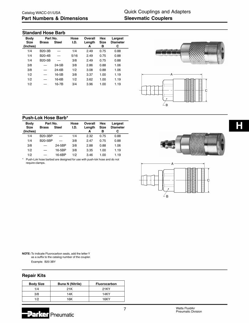
7 Watts FluidAirPneumatic Division
Pneumatic
Catalog WACC-01/USA
H
A
C
B
A
C
B
Standard Hose BarbBody Part No. Hose Overall Hex LargestSize Brass Steel I.D. Length Size Diameter
(Inches) A B C1/4 B20-3B — 1/4 2.49 0.75 0.881/4 B20-4B — 5/16 2.49 0.75 0.881/4 B20-5B — 3/8 2.49 0.75 0.88
3/8 — 24-5B 3/8 2.86 0.88 1.063/8 — 24-6B 1/2 3.08 0.88 1.061/2 — 16-5B 3/8 3.37 1.00 1.19
1/2 — 16-6B 1/2 3.62 1.00 1.191/2 — 16-7B 3/4 3.96 1.00 1.19
Push-Lok Hose Barb*Body Part No. Hose Overall Hex LargestSize Brass Steel I.D. Length Size Diameter
(Inches) A B C1/4 B20-3BP — 1/4 2.32 0.75 0.881/4 B20-5BP — 3/8 2.47 0.75 0.88
3/8 — 24-5BP 3/8 2.88 0.88 1.061/2 — 16-5BP 3/8 3.35 1.00 1.191/2 — 16-6BP 1/2 3.46 1.00 1.19
* Push-Lok hose barbsd are designed for use with push-lok hose and do notrequire clamps.
NOTE: To indicate Fluorocarbon seals, add the letter Yas a suffix to the catalog number of the coupler.
Example: B20 3BY
Body Size Buna N (Nitrile) Fluorocarbon
1/4 21K 21KY
3/8 14K 14KY
1/2 16K 16KY
Repair Kits
Quick Couplings and AdaptersSleevmatic CouplersPart Numbers & Dimensions

Watts FluidAirPneumatic Division
Pneumatic8
Catalog WACC-01/USA
OperationPush type couplings feature one-handed “automatic”connection by pushing the nipple into the coupler –provided the coupler half is firmly mounted.The locking mechanism of Saflomatic push typecouplers consists of pawls or pins which act directlyon the sleeve, thereby causing the sleeve toautomatically retract when the mating nipple isinserted. The sleeve must be manually retractedin order to remove the nipple.Saflomatic couplings are push type “single shut off”couplings.Common applications include compressed air, water,grease, paint, limited vacuum and limited gas.
Features1. Saflomatic tubular valves with their large flow
windows deliver high air flow with minimum pressuredrop – for efficient performance of air tools andother actuators. The tubular valve also provides 360degree seal support to prevent cold flow and boreconstriction, thereby extending seal life.
Specifications Body Size
1/4 3/8 1/2 3/4
Rated Pressure (psi) 300 300 300 300
Temperature RangeBuna N (Nitrile) -40°F to 250°FFluorocarbon -20°F to 400°F
Locking Device 3 pawls 4 pawls 5 pawls 6 pawls
Force required to connect (lbs)With 80 psi initial pressure 24 41 63 83With 100 psi initial pressure 26 44 69 95
Vacuum Data (inches Hg)*Disconnected (coupler only) Not recommendedConnected 27.4 27.4 27.4 27.4
*Couplings for vacuum service should be 100% tested – an extracost service. Consult factory.
PerformanceSaflomatic1/4" to 3/4"
- - - - 100 PSI80 PSI
(INLET PRESSURE)
200
1009080
70
60
50
40
30
20
101 2 3 4 5 6 7 8 9 10 20
Pressure Drop in PSID
Flo
w in
SC
FM
1/2"
3/4"
3/8"
1/4"
200
1009080
70
60
50
40
30
20
10
Quick Couplings and AdaptersSaflomatic CouplersFeatures & Specifications
2. Tapered flow recesses in the valve body providemaximum flow capability.
3. Precision molded seals with high quality valve seatsfor a bubble tight seal that assures reliable sealingwithin rated working pressures. The Saflomaticdesign with its 360° seal support gives maximumseal retention.
4. Locking pawls are of hardened stainless steel for adurable locking mechanism that provides goodalignment and sideload resistance.
5. Push-to-connect design permits one-handedconnection when the coupler half is rigidly mounted.
6. Back pressure vent holes allow easier connectionsespecially with liquids.
7. Hardened wear points and solid barstockconstruction provide long life for these qualitycouplings. Precision machined surfaces resist theeffects of mechanical shocks, even in rugged use.
8. Interchangeability. Saflomatic couplers are usedwith industrial interchange nipples conforming toMIL-C4109.
2
31
4
58
6
7

9 Watts FluidAirPneumatic Division
Pneumatic
Catalog WACC-01/USA
H
Quick Couplings and AdaptersSaflomatic Couplers - Pipe ThreadPart Numbers & Dimensions
A
C
B
A
C
B
NOTE: To indicate Fluorocarbon seals, add the letter Yas a suffix to the catalog number of the coupler.
Example: B33AY
Female Pipe ThreadBody Part Overall Hex LargestSize No. Thread Length Size Diameter
(Inches) Brass Size A B C
1/4 B33A 1/8-27 1.96 0.75 1.20
1/4 B33 1/4-18 1.96 0.75 1.20
1/4 B33E 3/8-18 2.03 0.81 1.20
3/8 B35C 1/4-18 2.26 0.88 1.39
3/8 B35 3/8-18 2.33 0.88 1.39
3/8 B35F 1/2-14 2.60 0.88 1.39
1/2 B37E 3/8-18 2.75 1.00 1.52
1/2 B37 1/2-14 2.97 1.00 1.52
1/2 B37G 3/4-14 3.21 1.25 1.52
3/4 B39F 1/2-14 2.86 1.31 1.90
3/4 B39 3/4-14 3.00 1.31 1.90
3/4 B39J 1-11½ 3.19 1.56 1.90
Male Pipe ThreadBody Part Overall Hex LargestSize No. Thread Length Size Diameter
(Inches) Brass Size A B C
1/4 B32A 1/8-27 2.03 0.75 1.20
1/4 B32 1/4-18 2.18 0.75 1.20
1/4 B32E 3/8-18 2.18 0.75 1.20
3/8 B34C 1/4-18 2.38 0.88 1.39
3/8 B34 3/8-18 2.44 0.88 1.39
3/8 B34F 1/2-14 2.57 0.88 1.39
1/2 B36E 3/8-18 2.92 1.00 1.52
1/2 B36 1/2-14 3.09 1.00 1.52
1/2 B36G 3/4-14 3.12 1.13 1.52
3/4 B38F 1/2-14 2.93 1.31 1.90
3/4 B38 3/4-14 2.95 1.31 1.90
3/4 B38J 1-11½ 3.12 1.31 1.90

Watts FluidAirPneumatic Division
Pneumatic10
Catalog WACC-01/USA
A
C
B
A
C
B
Standard Hose BarbBody Part Overall Hex LargestSize No. Hose Length Size Diameter
(Inches) Brass I.D. A B C
1/4 B30-3B 1/4 2.62 0.75 1.20
1/4 B30-4B 5/16 2.62 0.75 1.20
1/4 B30-5B 3/8 2.62 0.75 1.20
3/8 B34-5B 3/8 2.85 0.88 1.39
3/8 B34-6B 1/2 2.85 0.88 1.39
1/2 B36-6B 1/2 3.33 1.00 1.52
1/2 B36-7B 3/4 3.86 1.00 1.52
3/4 B38-6B 1/2 3.16 1.31 1.90
3/4 B38-7B 3/4 3.69 1.31 1.90
3/4 B38-8B 1 3.93 1.31 1.90
Push-Lok Hose Barb*Body Part Overall Hex LargestSize No. Hose Length Size Diameter
(Inches) Brass I.D. A B C
1/4 B30-3BP 1/4 2.45 0.75 1.20
1/4 B30-5BP 3/8 2.60 0.75 1.20
3/8 B34-5BP 3/8 2.82 0.88 1.39
1/2 B36-6BP 1/2 3.46 1.00 1.52
* Push-Lok hose barbs are designed for use with push-lok hose anddo not require clamps.
Body Size Buna N (Nitrile) Fluorocarbon
1/4 21K2 21KY
3/8 14K 14KY
1/2 16K 16KY
3/4 38K 38KY
Repair Kits
Quick Couplings and AdaptersSaflomatic Couplers - Hose BarbPart Numbers & Dimensions
NOTE: To indicate Fluorocarbon seals, add the letter Yas a suffix to the catalog number of the coupler.
Example: B30 3BY

11 Watts FluidAirPneumatic Division
Pneumatic
Catalog WACC-01/USA
H
ApplicationStandard Twist-Lock couplings are ideal for low tomedium air flows, such as air tools. Heavy-dutyTwist-Lock couplings are designed for greaterflow capacities.
Features• Engineered for speedy coupling and uncoupling.
Plug in to lock . . . twist to unlock.
• Adapter swivels to prevent hose kinks.
• Designed to protect against accidental uncoupling.
• A wide variety of types and sizes available.
OperationTo lock – plug in. To unlock – give the check unitsleeve a 1/8 turn.
Plug in for compressed air – when you need it – whereyou need it. Make it as accessable to your needs aselectricity. Install check units around your shop atstrategic locations – on walls, work benches, columns,etc. Equip your pneumatic tools, etc. with matingadapters and simply plug into the check unit. Actsexactly like electric sockets and plugs. Permits use ofshorter, more manageable lengths of hose. Designedfor compressed air use. Consult your distributor forother fluids.
SpecificationsBody: Zinc
Sleeve and adapter: Zinc plated
Seals: Buna N
Working pressure: Up to 250 PSIG
Temperature:
Standard: -10°F to 165°FHigh temperature option: -10°F to 400°F
Quick Couplings and AdaptersTwist-Lock Quick Connect CouplingsFeatures & Specifications
.84(21)
.47 (12)
.47 (20)
1.13 (29)
1.81 (50)
11/16 Hex
1/4-18Port
Dia.
00 2 4 6 8 10 12 14 16 18 20
5
10
15
20
25
30
35
40
Pressure Drop in PSID 80
100
Flo
w in
SC
FM
Twist-lock (1/4")
Flow Chart

Watts FluidAirPneumatic Division
Pneumatic12
Catalog WACC-01/USA Quick Couplings and AdaptersTwist-Lock Quick Connect CouplingsPart Numbers & Dimensions
Standard
Check Unit – Female ThreadPart Inlet Overall Maximum
Number Port Length DiameterTL-251-4FP 1/4 1.875" 1.125"
Check Unit – Male ThreadPart Inlet Overall Maximum
Number Pipe Thread Length DiameterTL-251-4MP 1/4 2.125" 1.125"TL-251-6MP 3/8 2.125" 1.125"
Adapter – Male ThreadPart Pipe
Number ThreadTL-254-2MP 1/8"
TL-254-4MP 1/4"
Adapter – Female ThreadPart
Number PortTL-254-2FP 1/8"TL-254-4FP 1/4"
Adapter – Serrated ShankPart For
Number Hose I.D.TL-254-4HB 1/4"TL-254-6HB 3/8"
Standard Check Unit Repair Kit – 21K

13 Watts FluidAirPneumatic Division
Pneumatic
Catalog WACC-01/USA
H
Quick Couplings and AdaptersTwist-Lock Quick Connect CouplingsPart Numbers & Dimensions
Heavy Duty
Check Unit – Female ThreadPart Inlet Overall Maximum
Number Port Length DiameterTL-501-4FP 1/4 2.188 1.50"TL-501-6FP 3/8 2.188 1.50"TL-501-8FP 1/2 2.500 1.50"
TL-501-12FP 3/4 2.562 1.50"
Check Unit – Male ThreadPart Inlet Overall Maximum
Number Port Length DiameterTL-501-6MP 3/8 2.312" 1.50"TL-501-8MP 1/2 2.750" 1.50"
Adapter – Male ThreadPart Pipe
Number ThreadTL-504-4MP 1/4"
TL-504-6MP 3/8"TL-504-8MP 1/2"TL-504-12MP 3/4"
Adapter – Female ThreadPart Pipe
Number ThreadTL-504-4FP 1/4"
TL-504-6FP 3/8"
Adapter – Serrated ShankPart For Hose
Number I.D.TL-504-4HB 1/4"TL-504-6HB 3/8"
TL-504-8HB 1/2"
Heavy Duty Check Unit Repair Kit – 16K
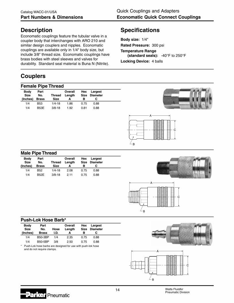
Watts FluidAirPneumatic Division
Pneumatic14
Catalog WACC-01/USA Quick Couplings and AdaptersEconomatic Quick Connect CouplingsPart Numbers & Dimensions
A
C
B
A
C
B
A
C
B
Specifications
Body size: 1/4"
Rated Pressure: 300 psi
Temperature Range(standard seals): -40°F to 250°F
Locking Device: 4 balls
DescriptionEconomatic couplings feature the tubular valve in acoupler body that interchanges with ARO 210 andsimilar design couplers and nipples. Economaticcouplings are available only in 1/4" body size, butinclude 3/8" thread size. Economatic couplings havebrass bodies with steel sleeves and valves fordurability. Standard seal material is Buna N (Nitrile).
Female Pipe ThreadBody Part Overall Hex LargestSize No. Thread Length Size Diameter
(Inches) Brass Size A B C1/4 B53 1/4-18 1.86 0.75 0.881/4 B53E 3/8-18 1.92 0.81 0.88
Male Pipe ThreadBody Part Overall Hex LargestSize No. Thread Length Size Diameter
(Inches) Brass Size A B C1/4 B52 1/4-18 2.08 0.75 0.881/4 B52E 3/8-18 2.11 0.75 0.88
Push-Lok Hose Barb*Body Part Overall Hex LargestSize No. Hose Length Size Diameter
(Inches) Brass I.D. A B C1/4 B50-3BP 1/4 2.35 0.75 0.88
1/4 B50-5BP 3/8 2.50 0.75 0.88* Push-Lok hose barbs are designed for use with push-lok hose
and do not require clamps.
Couplers
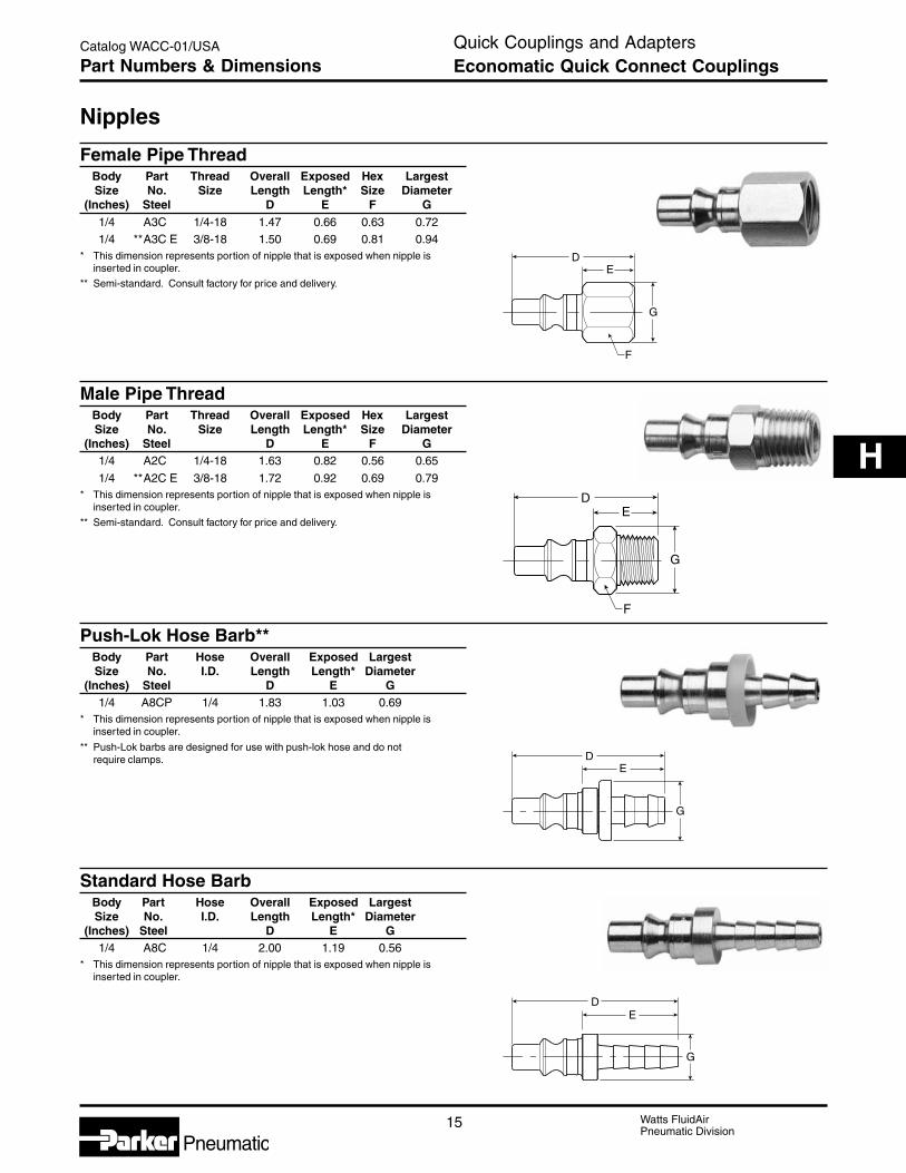
15 Watts FluidAirPneumatic Division
Pneumatic
Catalog WACC-01/USA
H
DE
G
DE
G
DE
G
F
DE
G
F
Nipples
Female Pipe ThreadBody Part Thread Overall Exposed Hex LargestSize No. Size Length Length* Size Diameter
(Inches) Steel D E F G1/4 A3C 1/4-18 1.47 0.66 0.63 0.721/4 **A3C E 3/8-18 1.50 0.69 0.81 0.94
* This dimension represents portion of nipple that is exposed when nipple isinserted in coupler.
** Semi-standard. Consult factory for price and delivery.
Male Pipe ThreadBody Part Thread Overall Exposed Hex LargestSize No. Size Length Length* Size Diameter
(Inches) Steel D E F G1/4 A2C 1/4-18 1.63 0.82 0.56 0.65
1/4 **A2C E 3/8-18 1.72 0.92 0.69 0.79* This dimension represents portion of nipple that is exposed when nipple is
inserted in coupler.
** Semi-standard. Consult factory for price and delivery.
Push-Lok Hose Barb**Body Part Hose Overall Exposed LargestSize No. I.D. Length Length* Diameter
(Inches) Steel D E G1/4 A8CP 1/4 1.83 1.03 0.69
* This dimension represents portion of nipple that is exposed when nipple isinserted in coupler.
** Push-Lok barbs are designed for use with push-lok hose and do notrequire clamps.
Standard Hose BarbBody Part Hose Overall Exposed LargestSize No. I.D. Length Length* Diameter
(Inches) Steel D E G1/4 A8C 1/4 2.00 1.19 0.56
* This dimension represents portion of nipple that is exposed when nipple isinserted in coupler.
Quick Couplings and AdaptersEconomatic Quick Connect CouplingsPart Numbers & Dimensions

Watts FluidAirPneumatic Division
Pneumatic
Catalog WACC-01/USA

Watts FluidAirPneumatic Division
Pneumatic
Catalog WACC-01/USA
Watts FluidAirPneumatic Division
Pneumatic
Catalog WACC-01/USA
The items described in this document and other documents or descriptions provided by Parker Hannifin Corporation, its subsidiar-ies and its authorized distributors, are hereby offered for sale at prices to be established by Parker Hannifin Corporation, itssubsidiaries and its authorized distributors. This offer and its acceptance by any customer (“Buyer”) shall be governed by all of thefollowing Terms and Conditions. Buyer’s order for any such item, when communicated to Parker Hannifin Corporation, its subsidiar-ies or an authorized distributor (“Seller”) verbally or in writing, shall constitute acceptance of this offer.1. Terms and Conditions of Sale: All descriptions, quotations, proposals,offers, acknowledgments, acceptances and sales of Seller’s products aresubject to and shall be governed exclusively by the terms and conditions statedherein. Buyer’s acceptance of any offer to sell is limited to these terms andconditions. Any terms or conditions in addition to, or inconsistent with thosestated herein, proposed by Buyer in any acceptance of an offer by Seller, arehereby objected to. No such additional, different or inconsistent terms andconditions shall become part of the contract between Buyer and Seller unlessexpressly accepted in writing by Seller. Seller’s acceptance of any offer topurchase by Buyer is expressly conditional upon Buyer’s assent to all the termsand conditions stated herein, including any terms in addition to, or inconsistentwith those contained in Buyer’s offer. Acceptance of Seller’s products shall in allevents constitute such assent.
2. Payment: Payment shall be made by Buyer net 30 days from the date ofdelivery of the items purchased hereunder. Amounts not timely paid shall bearinterest at the maximum rate permitted by law for each month or portion thereofthat the Buyer is late in making payment. Any claims by Buyer for omissions orshortages in a shipment shall be waived unless Seller receives notice thereofwithin 30 days after Buyer’s receipt of the shipment.
3. Delivery: Unless otherwise provided on the face hereof, delivery shall bemade F.O.B. Seller’s plant. Regardless of the method of delivery, however, riskof loss shall pass to Buyer upon Seller’s delivery to a carrier. Any delivery datesshown are approximate only and Seller shall have no liability for any delays indelivery.
4. Warranty: Seller warrants that the items sold hereunder shall be free fromdefects in material or workmanship for a period of 18 months from date ofshipment from Parker Hannifin Corporation. THIS WARRANTY COMPRISESTHE SOLE AND ENTIRE WARRANTY PERTAINING TO ITEMS PROVIDEDHEREUNDER. SELLER MAKES NO OTHER WARRANTY, GUARANTEE, ORREPRESENTATION OF ANY KIND WHATSOEVER. ALL OTHERWARRANTIES, INCLUDING BUT NOT LIMITED TO, MERCHANTABILITYAND FITNESS FOR PURPOSE, WHETHER EXPRESS, IMPLIED, OR ARISINGBY OPERATION OF LAW, TRADE USAGE, OR COURSE OF DEALING AREHEREBY DISCLAIMED.
NOTWITHSTANDING THE FOREGOING, THERE ARE NO WARRANTIESWHATSOEVER ON ITEMS BUILT OR ACQUIRED WHOLLY OR PARTIALLY,TO BUYER’S DESIGN OR SPECIFICATIONS.
5. Limitation of Remedy: SELLER’S LIABILITY ARISING FROM OR IN ANYWAY CONNECTED WITH THE ITEMS SOLD OR THIS CONTRACT SHALL BELIMITED EXCLUSIVELY TO REPAIR OR REPLACEMENT OF THE ITEMSSOLD OR REFUND OF THE PURCHASE PRICE PAID BY BUYER, ATSELLER’S SOLE OPTION. IN NO EVENT SHALL SELLER BE LIABLE FORANY INCIDENTAL, CONSEQUENTIAL OR SPECIAL DAMAGES OF ANYKIND OR NATURE WHATSOEVER, INCLUDING BUT NOT LIMITED TO LOSTPROFITS ARISING FROM OR IN ANY WAY CONNECTED WITH THISAGREEMENT OR ITEMS SOLD HEREUNDER, WHETHER ALLEGED TOARISE FROM BREACH OF CONTRACT, EXPRESS OR IMPLIED WARRANTY,OR IN TORT, INCLUDING WITHOUT LIMITATION, NEGLIGENCE, FAILURETO WARN OR STRICT LIABILITY.
6. Changes, Reschedules and Cancellations: Buyer may request to modifythe designs or specifications for the items sold hereunder as well as thequantities and delivery dates thereof, or may request to cancel all or part of thisorder, however, no such requested modification or cancellation shall becomepart of the contract between Buyer and Seller unless accepted by Seller in awritten amendment to this Agreement. Acceptance of any such requestedmodification or cancellation shall be at Seller’s discretion, and shall be uponsuch terms and conditions as Seller may require.
7. Special Tooling: A tooling charge may be imposed for any special tooling,including without limitations, dies, fixtures, molds and patterns, acquired tomanufacture items sold pursuant to this contract. Such special tooling shall beand remain Seller’s property notwithstanding payment of any charges by Buyer.In no event will Buyer acquire any interest in apparatus belonging to Seller whichis utilized in the manufacture of the items sold hereunder, even if such apparatushas been specially converted or adapted for such manufacture andnotwithstanding any charges paid by Buyer. Unless otherwise agreed, Seller
shall have the right to alter, discard or otherwise dispose of any special toolingor other property in its sole discretion at any time.
8. Buyer’s Property: Any designs, tools, patterns, materials, drawings,confidential information or equipment furnished by Buyer, or any other itemswhich become Buyer’s property, may be considered obsolete and may bedestroyed by Seller after two (2) consecutive years have elapsed without Buyerplacing an order for the items which are manufactured using such property.Seller shall not be responsible for any loss or damage to such property while itis in Seller’s possession or control.
9. Taxes: Unless otherwise indicated on the face hereof, all prices and chargesare exclusive of excise, sales, use, property, occupational or like taxes whichmay be imposed by any taxing authority upon the manufacture, sale or deliveryof the items sold hereunder. If any such taxes must be paid by Seller or if Selleris liable for the collection of such tax, the amount thereof shall be in addition tothe amounts for the items sold. Buyer agrees to pay all such taxes or toreimburse Seller therefore upon receipt of its invoice. If Buyer claims exemptionfrom any sales, use or other tax imposed by any taxing authority, Buyer shallsave Seller harmless from and against any such tax, together with any interestor penalties thereon which may be assessed if the items are held to be taxable.
10. Indemnity For Infringement of Intellectual Property Rights: Seller shallhave no liability for infringement of any patents, trademarks, copyrights, tradedress, trade secrets or similar rights except as provided in this Part 10. Sellerwill defend and indemnify Buyer against allegations of infringement of U.S.patents, U.S. trademarks, copyrights, trade dress and trade secrets (hereinafter“Intellectual Property Rights”). Seller will defend at its expense and will pay thecost of any settlement or damages awarded in an action brought against Buyerbased on an allegation that an item sold pursuant to this contract infringes theIntellectual Property Rights of a third party. Seller’s obligation to defend andindemnify Buyer is contingent on Buyer notifying Seller within ten (10) days afterBuyer becomes aware of such allegations of infringement, and Seller havingsole control over the defense of any allegations or actions including allnegotiations for settlement or compromise. If an item sold hereunder is subjectto a claim that it infringes the Intellectual Property Rights of a third party, Sellermay, at its sole expense and option, procure for Buyer the right to continue usingsaid item, replace or modify said item so as to make it noninfringing, or offer toaccept return of said item and return the purchase price less a reasonableallowance for depreciation. Notwithstanding the foregoing, Seller shall have noliability for claims of infringement based on information provided by Buyer, ordirected to items delivered hereunder for which the designs are specified inwhole or part by Buyer, or infringements resulting from the modification,combination or use in a system of any item sold hereunder. The foregoingprovisions of this Part 10 shall constitute Seller’s sole and exclusive liability andBuyer’s sole and exclusive remedy for infringement of Intellectual PropertyRights.
If a claim is based on information provided by Buyer or if the design for an itemdelivered hereunder is specified in whole or in part by Buyer, Buyer shall defendand indemnify Seller for all costs, expenses or judgements resulting from anyclaim that such item infringes any patent, trademark, copyright, trade dress,trade secret or any similar right.
11. Force Majeure: Seller does not assume the risk of and shall not be liablefor delay or failure to perform any of Seller’s obligations by reason ofcircumstances beyond the reasonable control of Seller (hereinafter “Events ofForce Majeure”). Events of Force Majeure shall include without limitation,accidents, acts of God, strikes or labor disputes, acts, laws, rules or regulationsof any government or government agency, fires, floods, delays or failures indelivery of carriers or suppliers, shortages of materials and any other causebeyond Seller’s control.
12. Entire Agreement/Governing Law: The terms and conditions set forthherein, together with any amendments, modifications and any different terms orconditions expressly accepted by Seller in writing, shall constitute the entireAgreement concerning the items sold, and there are no oral or otherrepresentations or agreements which pertain thereto. This Agreement shall begoverned in all respects by the law of the State of Ohio. No actions arising outof sale of the items sold hereunder or this Agreement may be brought by eitherparty more than two (2) years after the cause of action accrues.
Airline AccessoriesOffer of Sale

Watts FluidAirParker Hannifin CorporationPneumatic Division9 Cutts RoadKittery, ME 03904 USATel: (207) 439-9511Fax: (207) 475-4013
Customer/Technical Service
Tel: (877) 467-4323Fax: (207) 475-4004Web site: www.wattsfluidair.comE-mail: [email protected]
Catalog WACC-01/USA 4/03 10M IGS Printed in U.S.A.