air spring kit economy
TRANSCRIPT

8/3/2019 Air Spring Kit Economy
http://slidepdf.com/reader/full/air-spring-kit-economy 1/6
The premier source of parts and accessories for mini lathes and mini mills.
Installing the Economy Air Spring KitThe air spring kit replaces the torsion-spring head support on the mini mill and
provides greater travel on the Z-axis.
The economy air spring kit includes the following parts:
• One air spring
• One head support shaft
• One air spring lower mount
• One air spring upper mount
• One long Z-axis rack
• Four M6x12 flat socket head machine screws
• Two M6x16 socket head cap screws
• One M8x20 socket head cap screw
• One M8x30 socket head cap screw
• Two M8 hex nuts
• Two M10 hex nuts

8/3/2019 Air Spring Kit Economy
http://slidepdf.com/reader/full/air-spring-kit-economy 2/6
• A 9 mm, letter T, or 23/64” drill bit
• An electric hand drill
Expect to spend about one hour on this project.
Installation
Follow these steps to install the kit.
1. Remove the cover from the column.
2. Drill a hole 12.0” below the top of the
column casting, centered in the back of the column. Use a 9 mm, letter T, or23/64” drill bit.
3. Drill and tap two M6 holes into the top
of the spindle housing mount castingpositioned as shown on the Air SpringMounting Holes drawing at the end of this document. Use a 5.0 mm or #9(0.196”) drill bit. Use an M6x1.0 tap tothread the holes.
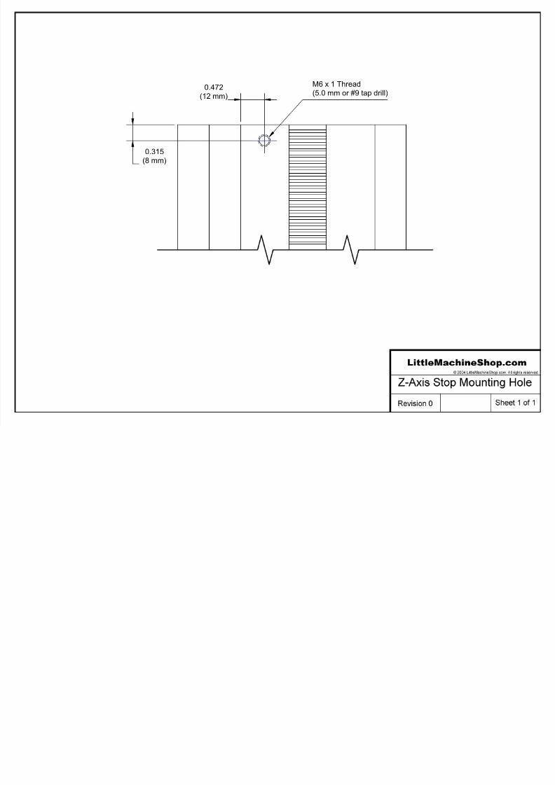
4. Drill and tap one M6 hole into the frontof the column casting positioned asshown on the Z-Axis Stop Mounting Holedrawing at the end of this document.

8/3/2019 Air Spring Kit Economy
http://slidepdf.com/reader/full/air-spring-kit-economy 3/6
5. Assemble the M8x30 socket head capscrew and an M8 hex nut on the rod
end of the air spring. Tighten the nutand cap screw securely.
6. Put an M10 nut on each end of the head support shaft.
7. Put the air spring lower mount on oneend of the head support shaft, and theair spring upper mount on the otherend.
8. Attach the air spring to the uppermount with the M8x20 socket head capscrew.
9. Remove the cap screw and plastic bushing that limits the upward travel of the Z-axis.
10. Move the head so the top is flush with the top of the column.
11. Remove the two flat head screws securing the rack and remove the rack.
12. Feed the new long rack into the slot in the column from the top. Use the Z-axis feed to run the rack down into position.
13. Install the two bottom M6x12 flat socket head machine screws to secure therack.
14. Move the head to its lowest position and install the two top M6x12 flatsocket head machine screws to finish securing the rack.
15. Move the head so the top is flush with the top of the column. Lock the head
in this position with the locking lever on the right side.16. Put the air spring assembly into the column with the M8x30 socket head cap
screw through the hole in the back of the casting. Secure with the M8 nutand washer.

8/3/2019 Air Spring Kit Economy
http://slidepdf.com/reader/full/air-spring-kit-economy 4/6
17. Attach the air spring mountingblock to the top of the spindle-
housing mount with two M6x16socket head cap screws.
18. Move the head down and install the cap screw and plastic bushing thatlimits the upward travel of the Z-axis.
19. Move the head to the top position and lock it in place. Remove the torsionspring assembly. Remove the anchor pin at the end of the arm first. You cancontrol the spring by pressing down on the end of the arm. Thendisassemble the spring pivot shaft and remove it.

8/3/2019 Air Spring Kit Economy
http://slidepdf.com/reader/full/air-spring-kit-economy 5/6
0.709(18 mm)
M6 x 1 Thread(5.0 mm or #9 tap drill)
Spindle Housing Mount
2.362
(60 mm)
8/3/2019 Air Spring Kit Economy
http://slidepdf.com/reader/full/air-spring-kit-economy 6/6
0.315(8 mm)
0.472
(12 mm)
M6 x 1 Thread
(5.0 mm or #9 tap drill)