air pollution control for gas turbines - … · air pollution control for gas turbines . topsøe -...
TRANSCRIPT

Craig Sharp, Key Account manager
Nathan White, Director – Air Pollution Control Catalyst & Technology
September 19, 2013
Mcllvaine Hot Topic Hour Air pollution control for gas turbines

Topsøe - A global supplier of catalysts and technologies
Copenhagen Moscow
Beijing
Bahrain New Delhi
Buenos Aires
Alberta
Kuala Lumpur
Los Angeles Houston
Headquarters Topsøe offices Research Production Engineering Sale & Marketing
Subsidiaries
Haldor Topsoe, Inc.
Haldor Topsøe International A/S, Denmark
Haldor Topsoe India Pvt. Ltd. India
ZAO Haldor Topsøe, Russia
Subcontinent Ammonia Investment Company ApS (SAICA)
Topsoe Fuel Cell A/S, Denmark
Rio
Cape Town
Tokyo
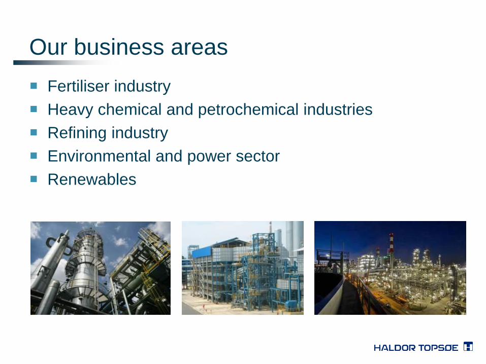
Our business areas
Fertiliser industry
Heavy chemical and petrochemical industries
Refining industry
Environmental and power sector
Renewables

… and a leading market player
Market share between 15-25% for established products
Supplier of solutions for 50% of new ammonia plants built
within the last decade
More than 60% of ammonia is produced worldwide on Topsøe
catalyst
Supplier for 40% of catalysts for production of ultra-low
sulphur diesel
30% market share of hydrogen catalysts
30% market share of FCC pretreatment catalysts
References account for 60% of the worlds industrial
production

Technologies cont.
Environmental technologies
– DeNOx (SCR DNX® catalyst): Removal of nitrogen oxides
Coal fired power plants
Gas fired boilers
Diesel and gas engines
Waste incinerators
Co-Gen units
Single cycle
Furnaces
FCC unit
Other refinery processes
Hydrogen units
– WSA: Sulphur removal
– SNOX : Combined WSA/DeNOx
– CATOX/REGENOX: VOC removal

Haldor Topsoe’s SCR Catalyst Products
Homogeneously Corrugated Composite SCR Catalyst
TiO2 with V2O5 as the principal active component including WO3
Design temperature range: 300 – 1,050oF
low temperature SCR → higher V:W ratio
high temperature SCR → low V:W ratio (low V to no V catalyst is optimal choice for simple cycle SCR if no dilution air is used
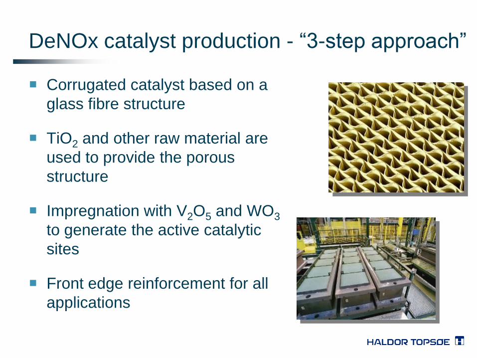
DeNOx catalyst production - “3-step approach”
Corrugated catalyst based on a
glass fibre structure
TiO2 and other raw material are
used to provide the porous
structure
Impregnation with V2O5 and WO3
to generate the active catalytic
sites
Front edge reinforcement for all
applications

Catalyst Performance –
Benefits of a meso- and macro-pore
Flue gas flow
NO N2
NO NO
Homogeneous pore system Tri-modal pore system
Macro-pore Meso-pore Micro-pores Micro-pore

Catalyst Performance
New Jersey Combined Cycle GE7FA
DNX® Catalyst Installed (2001)
Guarantees:
3.5-ppmvdc Outlet NOx
86% DeNOx
5-ppmvdc NH3 slip
2.0 in. wc draft loss
3-yrs life

Catalyst Performance
Alabama Combined Cycle Siemens 501F
DNX-929 Catalyst Installed (2010)
Power Output increased by 3.7 MW
Ammonia usage decreased by over 50%

HTI Experience
• Utility Boilers 80 units
• Combustion Turbines 352 units
• including (> 800 F up to 1,050 F) 135 units
• Refinery & Industrial Boilers, Heaters 328 units
• Stationary Diesel and Gas Engines 56 units
Total Experience 816 units
* Additional HTAS experience of ~ 400 units includes refinery units.
* Leading supplier of Combustion Turbine, Refinery, and Industrial DeNOx catalyst in the US.

SCR Process Basics
Flue Gas: NOx, SOx, CO2, O2
Clean Gas : N2, H2O, O2, SO2, (SO3)
SCR = Selective Catalytic Reduction
Purpose is to reduce NOx from flue gas.
A reducing agent, most commonly ammonia (NH3), is injected into the flue gas via an Ammonia Injection Grid (AIG).
– The NH3 must be distributed thoroughly into the gas stream prior to the catalyst.
– The mixed gas then passes through the catalyst layers where the NH3 reacts with NOx on the catalyst surface and in the pores to form N2 and H20 vapor.
NH3

SCR Design Considerations
Performance Requirements
(NOx Reduction, NH3 slip, DP, Service Life)
Exhaust Gas
(Composition, Flow, Temp)
System Mal-distribution
(Flow, NH3 /NOx, Temp)
Catalyst Formulation and Volume
CO Catalyst Placement
(NO2/NOx Ratio)
AIG, Mixer Plates, Seal Design
(Location, Mal-distribution, Type)
Load Dispatch
(AGC, Bandwidth)
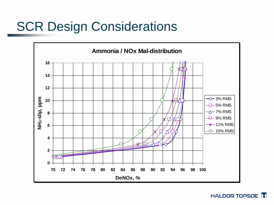
SCR Design Considerations
Ammonia / NOx Mal-distribution
0
2
4
6
8
10
12
14
16
70 72 74 76 78 80 82 84 86 88 90 92 94 96 98 100
DeNOx, %
NH
3-s
lip
, p
pm 3% RMS
5% RMS
7% RMS
9% RMS
11% RMS
15% RMS

SCR Design Considerations
Flow Mal-distribution
0
2
4
6
8
10
12
14
16
70 72 74 76 78 80 82 84 86 88 90 92 94 96 98 100
DeNOx, %
NH
3-s
lip
, p
pm
10% RMS
15% RMS
20% RMS
25% RMS
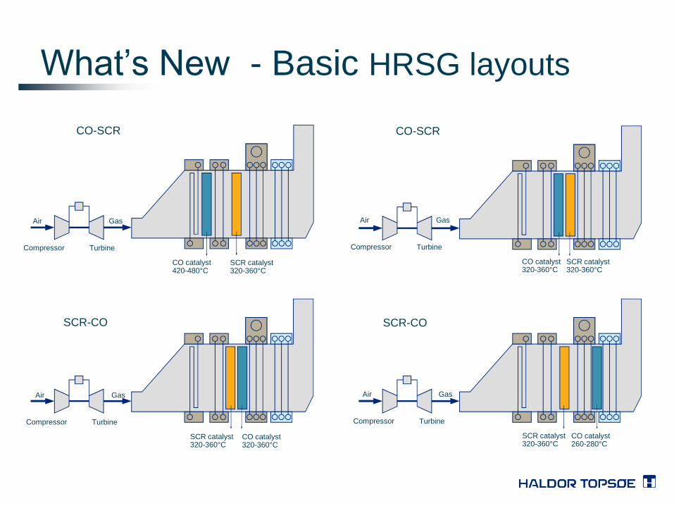
What’s New - Basic HRSG layouts
Compressor Turbine
Air Gas
CO catalyst 420-480°C
SCR catalyst 320-360°C
Compressor Turbine
Air Gas
CO catalyst 320-360°C
SCR catalyst 320-360°C
Compressor Turbine
Air Gas
SCR catalyst 320-360°C
CO catalyst 320-360°C
Compressor Turbine
Air Gas
SCR catalyst 320-360°C
CO catalyst 260-280°C
CO-SCR CO-SCR
SCR-CO SCR-CO

New Developments for CO (DNO) Catalyst
DeNOx Guarantees:
12.24 lb/hr Outlet NOx
90% DeNOx @ 10-ppmvdc NH3 slip
2-yrs life
CO Guarantees:
98% Outlet CO Conversion
41% Outlet VOC (C6+) Conversion
2-yrs life
Pennsylvania Plant: NOx Catalyst (DNX-929), CO Catalyst (DNO-1920) Installed (April 2011)
DNO
DNX Flue Gas /
NH3 Flow

Haldor Topsoe, Inc.
Thank you
Questions
Craig Sharp
Key Account Manager
(281) 228-5138
Nathan White
Director, Air Pollution Control Catalyst & Technology
(803) 835-0571