air force materiel command - nasa · pdf fileair force materiel command developing, ......
TRANSCRIPT

Air Force Materiel Command
Developing, Fielding, and Sustaining America’s Aerospace Force
I n t e g r i t y - S e r v i c e - E x c e l l e n c e
Pressure and Hazardous
Material Systems (PHMS)
Certification
10 May 2011
Bob Walker
Technical Director
USAF/AEDC
AEDC-2011-060 Distribution Statement A Public Release

$11.3 billion replacement value
5-year funding average: $ 368 million
• Approximately 2,400 people
employed including military,
government civilians, and
contractor personnel
• Approximately 40,000 acres
encompassing a 4,000 acre
industrial site
NFAC
Mountain View, CA
43 test cells
Tunnel 9
White Oak, MD

Outline
• Purpose/Significance
• The Goal of Certification
• Program History at AEDC
• What Qualifies as PHMS?
• The Certification Process
• Current Status
• Future Expectations
• Summary
3

Purpose/Significance
• The purpose of this briefing is to familiarize the
conference attendees with PHMS Certification
• Significance of certification
– Required to perform the mission.
– Aging systems, budgets stretched to cover mnx
– Systems lack tech data and configuration history.
– No in-service inspection
– Severe system failures (NASA, DoD and Industry).
– Significant potential energy (hazard/severity)
– We have demonstrated certification can be
performed at a fraction of replacement cost (10%)
4

Intent
• Bring aged/unknown configurations up to Code.
• Reduce operational risk/lower probability of
failure.
• New PHMS would be acquired and maintained
to Code by other projects.
• Once a system is certified, it would be
maintained in a certified condition-
configuration.
5

The Goal of Certification
1. Provide the baseline documentation
verifying that a pressure system was
designed, constructed, inspected,
repaired and tested in accordance with
applicable codes and standards.
2. Provide a system that is considered
safe for operation at AEDC.
3. Create ISI plans and PM procedures
a) To maintain certification.
b) Monitor for areas of degradation in the
future.
6

Program History at AEDC
• AEDC program began in 1989 with award
of certification contract.
– Approximately $3M/year program ($60M/20
yrs).
– 150 original systems.
– Decisions at initial contract award not to
include J6, ASTF, SL, Hydraulics.
• AEDC PHMS Systems have a
replacement value > $500M (estimate) .
7

Program History at AEDC
8
ETF – B
APTU HPA
PWT Tunnels
ETF – A
Surplus Vessels
ASTF
PHMS
Certification
O&M
ISI-PMs
New PHMS
Fuels
High Pressure Air
???
GN2
Helium - MKI
1950s 1960s 1970s 1980s 1990s 2000s 2010s ???s

PHMS by Definition
• Non-Category D pressure systems
– The design gauge pressure exceeds 150 psi
– The design temperature is less than -20 or
greater than 366°F
– The fluid handled is flammable or toxic
• Any additional system that is deemed to be
mission critical can be included.
• Defined in AEDC Safety and Pressure Design
Standards.
9

Exclusions
– Plumbing, Sewer Systems, Potable Water
Supply Piping.
– Non-Industrial Fire Sprinkler Piping.
– Electrical Conduit.
– Test Articles.
– Facility Heating, Ventilating, and Air
Conditioning.
– Piping of Plastic, Glass, or Any Nonmetallic
Material.
Note: Defined in AEDC Safety and Pressure
Design Standards.
10

Types of Systems Certified by PHMS
11
High Pressure Air

Types of Systems Certified by PHMS
• Gaseous Nitrogen
12

Types of Systems Certified by PHMS
• Liquid Nitrogen
13

Types of Systems Certified by PHMS
• Liquid Oxygen
14
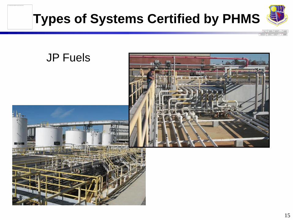
Types of Systems Certified by PHMS
15
JP Fuels

Types of Systems Certified by PHMS
• Steam
16

Types of Systems Certified by PHMS
• Fire Suppression
17
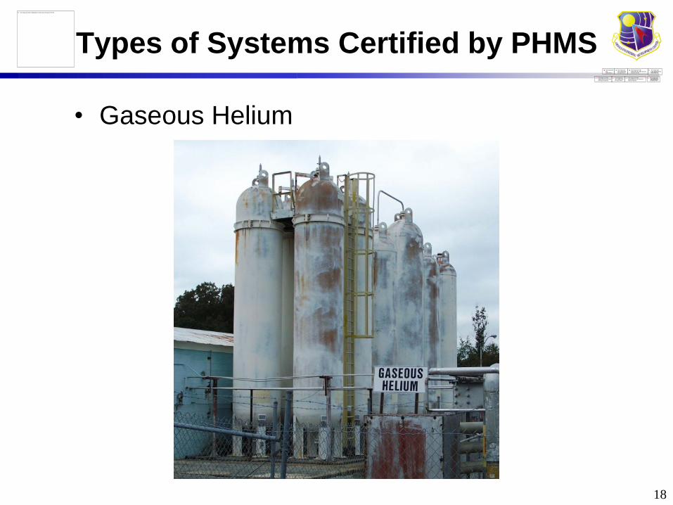
Types of Systems Certified by PHMS
• Gaseous Helium
18
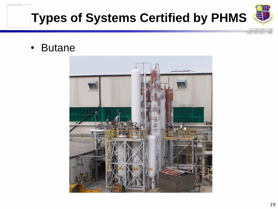
Types of Systems Certified by PHMS
• Butane
19

Types of Systems Certified by PHMS
• Process Air (Wind Tunnel Ducting)
20

Certification Requirements
• A pressure system is certified when inspection, analysis, and testing are performed and documented in accordance with the requirements of AEDC Engineering & Safety Standards.
• Certification of an existing system whose history is not well documented, may be accomplished through reverse engineering/analysis, inspection, and test.
• Existing systems shall be certified as resources become available or when modified.
• Certification documentation for pressure systems, provided in a Certification Report, shall be retained by the support contractor or organization responsible for the pressure system.
21

The Certification Report
• PHMS CERTIFICATION REPORT.
– The Certification Report includes
documentation verifying that a pressure
system was designed, inspected, and
tested in accordance with AEDC-ENGR-
STD-T-2 and is safe for operation at AEDC.
– The Certification Report is broken down
into 8 sections at AEDC.
22

8 Steps to Certification
• Section 1.0
– Project Plan
• This section defines the technical approach
used to certify the piping system.
• This section shall include a description of the
system, existing records, the design and
operating conditions, as well as man-hour
estimates and schedule.
– Non-Destructive Examination (NDE) Plan
• This section contains the initial NDE to confirm
design parameters and identify deficiencies.
• NDE requirements, acceptance criteria, and
supporting tasks are also contained here.
23

8 Steps to Certification
• Kickoff meetings are held with Asset
Owners, System Engineers, and PHMS
Personnel.
24

8 Steps to Certification
• Section 2.0: Config Identification Report
– Collection and review of available
documentation pertaining to the Project.1. System Schematics and Fabrication or Construction
Drawings
2. Device and Component Data
3. Dimensional and As-built Data
4. Piping and Component Material Identification
– System schematic redlined to reflect the
current configuration.
– Device and component ratings verified.
– List of deficiencies found during the
identification effort.
25

Sample of a Redlined Schematic
26

Working
Drawing
Field Walkdown
Identification Report
Drawing
Verification of Field Configuration
27

8 Steps to Certification
• Section 3.0: Evaluation Report– This section shall include calculations performed to
verify existing system design.
– The evaluation identifies localized problems.
• inadequate pipe wall thickness
• incorrect pressure rating
• inadequate piping supports
– All pressure retaining components of the piping
system are reviewed to determine that their
allowable pressure ratings are adequate for the
system design.
– Relief valve certification, pressure gauge calibration
and system safety issues are addressed.
– A combination of fatigue, fracture and finite element
analyses may be used to analyze indications
identified during nondestructive evaluation (NDE). 28

CAESAR II Pipe Stress and Flexibility
Analysis
• To confirm that it is safe to operate the system at
pressures up to the design conditions and within
the operating envelope.
29
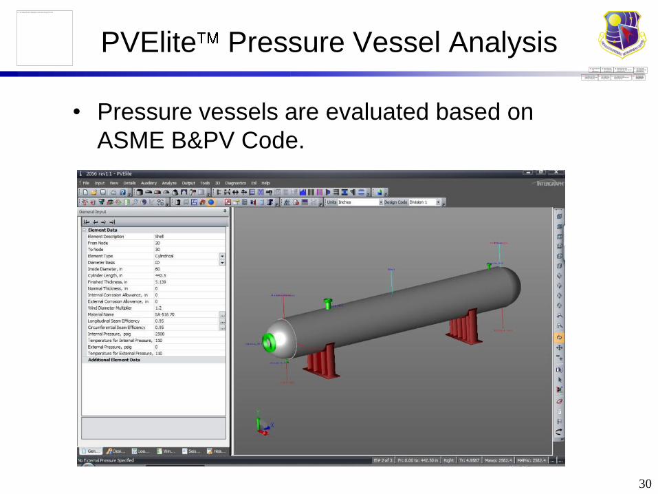
PVElite Pressure Vessel Analysis
30
• Pressure vessels are evaluated based on
ASME B&PV Code.

8 Steps to Certification
• Section 4.0 - NDE
– All accessible surfaces of piping, vessels,
devices, components & supports are
visually examined.
– UTT measurements are taken to verify wall
thickness and aid in evaluating areas of
corrosion.
– A weld map identifying major components
of the system and approximate weld
locations is created.
– All thickness measurements and any
deficiencies identified are forwarded to
engineering for evaluation and disposition.
31

Typical Inspections Performed
• Visual Examination (VT)
– Piping and Vessels / Internal and External
• Ultrasonic Thickness Testing (UTT)
• Magnetic Particle Testing (MT)
• Liquid Penetrant Testing (PT)
• Radiographic Testing (RT)
• Bubble Leak Testing (BLT)
• Additional Methods Available
32

Common Defects
Each piping system, including components and workmanship,
shall be examined in accordance with the applicable
requirements of AEDC Engineering Standards and National
Consensus Codes. Techniques used include: Visual,
Ultrasonic Thickness, Magnetic Particle , Liquid Penetrant, and
Radiographic tests.
Welds
Supports
OtherDefects
Configuration
Deficiencies
Design
Deficiencies
Maintenance

0
20
40
60
80
100
120
Incomplete Penetration Incomplete Fusion Exceeding Branch Opening Requirement
Underfill Excessive Spatter
Occu
rren
ces
Most Common Weld Defects
Weld Defects Summary (6 Projects)

Visual Examination
35

Ultrasonic Thickness
36

Magnetic Particle
37
Crack in Saddle Support Weld

Liquid Penetrant
38

Radiographic Testing
39
Uncommon Defect
No Thread Engagement
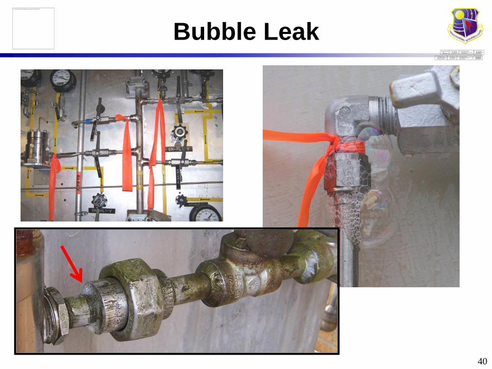
Bubble Leak
40

Additional Methods
• UT Volumetric/Shear Wave Testing
• Eddy Current Testing
• Acoustic Emission Testing
• Helium Mass Spectrometer Test
• Magnetic Flux Leakage Testing
• Vacuum Decay Test
• Cold Shock Test
• Bore Scope/Bore Probe
• Hydrostatic Pressure/Leak Test
• Pneumatic Pressure/Leak Test
41

Planning and Tracking NDE
NDE Traveler
NDE Matrix
42

8 Steps to Certification
• Section 5.0 - Monitor Report & Deficiency
Correction
• Documentation of repairs and corrections
made as a result of inspection or analysis.
• Documents shall include.
– Repair procedures used
– Follow up NDE Reports
– Revised drawings
– Additional calculations as necessary
43

8 Steps to Certification
• Section 6.0 - Final Certification Tests.
– Pressure system test certificates shall be
completed for each test.
– This section shall include documentation verifying
pressure system relief devices and pressure
gauges have been pressure tested or calibrated for
the intended service.
– Relief device certificates shall specify model
number, serial number, set points, orifice size, flow
capacity verified, and signature of test technician.
– Gauges shall be checked against a calibrated gauge
during system pressure test.
44

8 Steps to Certification
• Section 7.0 In-Service Inspection/Test Plan.• To maintain confidence in the safety of certified
systems, an in-service inspection test program shall be established and executed.
• Inspection is performed as part of the Center’s preventive maintenance program to ensure continued safe, reliable and effective operation as well as to maintain the certification of the PV/S.
• The system specification must be reviewed to ensure it remains accurate and current.
• During walkdown, components or devices must be examined for damage, wear, corrosion, loose, missing parts, etc.
• Any problem and/or discrepancy must be forwarded for resolution.
45

8 Steps to Certification
46
8 Steps to Certification
• Section 8 - Summary of Conclusions
and Recommendations.
– This section consists of any other
additional data necessary to document the
certification, such as a Physical
Configuration Audit (PCA) certificate.
– A pressure test IAW applicable Code
serves as the Functional Configuration
Audit (FCA)
Note: Certification does not include flow or
system efficiency analysis.
47

Results of Certification
Existing Pipe
Under Insulation After Repair
48
Inspected

Results of Certification
Crack at Branch Weld Repaired
49

Results of Certification
Pressure Vessels with
Multiple Defects
New Replacement
Vessels
50

Results of Certification
51
Radiograph showing
Rejectable Weld
Indications
Indications in Weld are
RemovedWeld Repaired

Current Status
• Completed 159
– Projects Completed 149
– Studies Completed 10
• In Progress 63
– Evaluation Phase 30
– Repair Phase 33
• Stopped/cancelled 56
• To be Started 59
• Total Projects 337
• Adds (FY11) – J4/J6 Steam Distribution
– Arcs HPA
• Potential Adds (hydraulics)
52

Program Funding
53
0.023
0.901 0.8960.96 0.985 0.993
1.152
1.513
1.241.353
1.413
1.1671.277 1.253
1.384 1.43
1.927
2.177 2.1942.277
2.476
1.708
1.75
0
0.5
1
1.5
2
2.5
3
1989 1990 1991 1992 1993 1994 1995 1996 1997 1998 1999 2000 2001 2002 2003 2004 2005 2006 2007 2008 2009 2010 2011
GP PHMS
ATA PHMS
1989 1990 1991 1992 1993 1994 1995 1996 1997 1998 1999 2000 2001 2002 2003 2004 2005 2006 2007 2008 2009 2010 2011
GP PHMS0.023 0.901 0.896 0.96 0.985 0.993 1.152 1.513 1.24 1.353 1.413 1.167 1.277 1.253 1.384 1.43 1.927 2.177 2.194 2.277 2.476 1.708 1.75
ATA PHMS 1.347 1.734 2.037 1.721 1.547 1.644 1.675 1.4 1.484 1.448 1.051 1.277 1.029 0.903 0.544 0.268 0.432 1.387 1.04 0.962 0.928 0.991
PHMS Activities 116 116 116 116 116 116 190 190 190 190 190 190 190 193 205 226 244 268 269 271 316 324 335

Project Level MetricsP
HM
S
Pro
jec
t #
Project Tile Milestone Description of WorkMilestone
completed
%
CompNotes
MHr.
est.
Points
avail
Points
achieved
Evaluation Phase
2237 VKF GN2 Bottle- seal air Kick off Kick off project and evaluation 11/18/2010 100%Placed on the stopped
work list.
2235 VKF Dryer 19-HPA Kick off Kick off project for evaluation 11/18/2010 100%
0107 J6 GN2 Vessels GP Eval/insp Ves 1 & 2 Eval, clean, Hydro, and reinstall 40% in repair112
add
0107 J6 GN2 VesselsGP evaluation/insp
vessel 3 & 4
Disconnect, remove, evaluate,
clean, Hydro, and reinstall0%
Repair Phase
3010 C2 GN2 repair/replacerecert. R.V.'s, replace underrated
parts, make weld repairs0%
no access due to
testing
3017 ASTF Heater fuel repair/replacereplace underrated parts, make
weld repairs, modify supports0%
no access due to
testing
0108 J6 LN2 repair/replacereplace underrated parts, make
weld repairs, modify supports0%
in repair pulled up
due to ASTF test
3002 C1 & C2 GN2 Dist. repair/replacereplace underrated parts, make
weld repairs, modify supports0%
no access due to
testing
2069 VKF H1B Heater Piping repair/replace additional repairs 0% in work 80
2051 VKF Process Air Dryer repair/replacereplace underrated parts, make
weld repairs, modify supports0%
as much repair as
outage allows
3003-1 ASTF Fuel System #1 repair/replace repair cracks in welds 0%in repair(pulled up
due to testing)
Close out/PM Establishment
2069 VKF H1B Heater Piping Close out Document repairs & mods for GP 90%
2250 VKF Seal Air Sys. HPA Close out Document repairs & mods for GP 95%
3001 ASTF GN2 System Close out Pressure test/closeout 80%
Backlog = 3 or more years in evaluation or 2 or more years in repair phase
54

Future Expectations
• Carryovers, new starts, etc (previously discussed).
• Process Improvements – Initiatives.
– New PHMS database created by AF.
– GP-ATA working on PHMS process improvements
rolled up from evaluation reports.
– Working to combine FMEA-Certification processes.
– Working to close gaps in HP AIR AP-7200.
– Working new kick-off and close-out KPI/OI.
– Summary of deficiencies and defects to help us
improve overall PHMS maintenance and repair.
– Looking at ways to improve new acquisitions, designs,
maintenance, welding, material selection, etc.
55

Additional FY11 Actions
• Update T Standards.
– ASME/NB-23 issues (OSHA).
– New vessels should be Code Stamped.
– Issue is with existing non-stamped vessels
requiring repair or alteration.
– AFI requires regular hydro tests and other
requirements AEDC-does not concur.
• Making sure our outside contractors
deliver quality welding, properly designed
PHMS and records are filed and updated
per T Stds.
56

Summary
• Program supports mission and reduces risk.
• Improvement noted in completing repairs and
closeout.
• Growing number of projects – less funding.
– Other efforts that manage PHMS should be
ensuring “re-certification” is not required and
that certification is maintained.
– We have averaged 8 projects/yr.
– This adds up to 8 more years w/no more adds.
• The importance of sustaining certification and
keeping remaining life up to date cannot be
overstated!
57

Questions?
58