air cooled heat pump for external installation
TRANSCRIPT

M0M140F14-00 22/07/2014
ELFOEnergy Magnum
Installation and operating manual
Air cooled heat pump for external installation
WSAN-XIN 18.2 - 30.2

Dear Customer,
We congratulate you on choosing this product
For many years Clivet has been offering systems that provide maximum comfort, together with high reliability, efficiency, quality and safety.
The aim of the company is to offer advanced systems, that assure the best comfort, reduce energy consumption and the installation and maintenance cost for the life cycle of the system.
The purpose of this manual is to provide you with information that is useful from reception of the equipment, through installation, operational usage and finally disposal so that this advanced system offers the beat solution.
Yours faithfully.
CLIVET Spa
The data contained in this manual is not binding and may be changed by the manufacturer without prior notice.Reproduction, even is part, is FORBIDDEN © Copyright - CLIVET S.p.A. - Feltre (BL) - Italia
M0M140F14-00 WSAN-XIN 18.2-30.2 3
Index of contents 1 General description 4
2 Reception 6
3 Positioning 8
4 Water connections 9
5 Electrical connections 13
6 Start-up 16
7 Control 20
8 Maintenance 24
9 Alarms - Status 27
10 Accessories 34
11 Decommissioning 48
12 Residual risks 49
13 Technical information 50
14 Dimensional drawings 52
15 Notes 54

4 WSAN-XIN 18.2-30.2 M0M140F14-00
1 General descriptionThe manual provides correct unit installation, use and maintenance.
Pay particular attention to:
Warning, identifies particularly important operations or information.
Prohibited operations that must not be carried out, that compromise the operating of the unit or may cause damage to persons or things.
• It is advisable to read it carefully so you will save time during operations.
• Follow the written indications so you will not cause damages to things and injuries people.
1.1 Manual
1.2 PreliminariesOnly qualified personnel can operate on the unit, as required by the regulation in force.
1.3 Risk situationsThe unit has been designed and created to prevent injures to people.
During designing it is not possible to plane and operate on all risk situation.
Read carefully “Residual risk” section where all situation which may cause damages to things and injuries to people are reported.
Installation, starting, maintenance and repair required specific knowledge; if they are carried out by inexperienced personnel, they may cause damages to things and injuries people.
1.4 Intended useUse the unit only:
• for cooling/heating water or a water and glycol mix for air-conditioning only
• keep to the limits foreseen in the technical schedule and in this manual
The manufacturer accepts no responsibility if the equipment is used for any purpose other than the intended use.
1.5 InstallationThe positioning, hydraulic system, refrigerating, electrics and the ducting of the air must be determined by the system designer in accordance with local regulations in force.
Follow local safety regulations.
Verify that the electrical line characteristics are in compliance with data quotes on the unit serial number label.
1.6 MaintenancePlan periodic inspection and maintenance in order to avoid or reduce repairing costs.
Turn the unit off before any operation.
1.7 ModificationAll unit modifications will end the warranty coverage and the manufacturer responsibility.
1.8 Breakdown/MalfuctionDisable the unit immediately in case of breakdown or malfunction.
Contact a certified service agent.
Use original spares parts only.
Using the unit in case of breakdown or malfunction:
• voids the warranty
• it may compromise the safety of the unit
• may increase time and repair costs
M0M140F14-00 WSAN-XIN 18.2-30.2 5
1.9 User trainingThe installer has to train the user on:
• Start-up/shutdown
• Set points change
• Standby mode
• Maintenance
• What to do / what not to do in case of breakdown
1.10 Data updateContinual product improvements may imply manual data changes.
Visit manufacturer web site for updated data.
1.11 Indications for the UserKeep this manual with the wiring diagram in an accessible place for the operator.
Note the unit data label so you can provide them to the assistance centre in case of intervention (see “Unit identification” section).
Provide a unit notebook that allows any interventions carried out on the unit to be noted and tracked making it easier to suitably note the various interventions and aids the search for any breakdowns.
In case of breakdown or malfunction:
• Immediately deactivate the unit
• Contact a service centre authorized by the manufacturer
The installer must train the user, particularly on:
• Start-up/shutdown
• Set points change
• Standby mode
• Maintenance
• What to do / what not to do in case of breakdown
1.12 Unit indentificationThe serial number label is positioned on the unit and allows to indentify all the unit features.
The matriculation plate must never be removed.
The matriculation plate shows the indications foreseen by the standards, in particular:
• unit type
• serial number (12 characters)
• year of manufacture
• wiring diagram number
• electrical data
• manufacturer logo and address
1.13 Serial numberIt identifies uniquely each unit.
Must be quoted when ordering spare parts.
1.14 Assistance requestNote data from the serial number label and write them in the chart on side, so you will find them easily when needed.
Series
Size
Serial number
Year of manufacture
Electrical wiringdiagram

6 WSAN-XIN 18.2-30.2 M0M140F14-00
2 Reception
You have to check before accepting the delivery:
• That the unit hasn’t been damaged during transport
• That the materials delivered correspond with that indicated on the transport document comparing the data with the identification label positioned on the packaging.
In case of damage or anomaly:
• Write down on the transport document the damage you found and quote this sentence: “Conditional acceptance clear evidence of deficiencies/damages during transport”
• Contact by fax and registered mail with advice of receipt to supplier and the carrier.
Any disputes must be made within 8 days from the date of the delivery. Complaints after this period are invalid.
2.1 StorageObserve external packaging instructions.
2.2 Handling1. Verify unit weight and handling equipment lifting capacity.
2. Identify critical points during handling (disconnected routes, flights, steps, doors).
3. Suitably protect the unit to prevent damage.
4. lifting brackets
5. Lifting with balance
6. Lifting with spacer bar
7. Align the barycenter to the lifting point
8. Use all the lifting brackets (see the dimensional section)
9. Gradually bring the lifting belts under tension, making sure they are positioned correctly.
10. Before starting the handling, make sure that the unit is stable.

M0M140F14-00 WSAN-XIN 18.2-30.2 7
2.3 Packaging removingBe careful not to damage the unit.
Keep packing material out of children’s reach it may be dangerous.
Recycle and dispose of the packaging material in conformity with local regulations.
8 WSAN-XIN 18.2-30.2 M0M140F14-00
3 PositioningDuring positioning consider these elements:
• Technical spaces requested by the unit
• Electrical connections
• Water connections
• Spaces for air exhaust and intake
3.1 Functional spacesFunctional spaces are designed to:
• guarantee good unit operation
• carry out maintenance operations
• protect authorized operators and exposed people
Respect all functional spaces indicated in the DIMENSIONS section.
Double all functional spaces if two or more unit are aligned.
3.2 PositioningUnits are designed to be installed:
• EXTERNAL
• in fixed positions
Limit vibration transmission:
• use antivibration devices on unit bearing points
• install flexible joints on the hydraulic connections
Choose the installation place according to the following criteria:
• Customer approval
• safe accessible position
• technical spaces requested by the unit
• spaces for the air intake/exhaust
• max. distance allowed by the electrical connections
• avoid flood-prone places
• verify unit weight and bearing point capacity
• verify that all bearing points are aligned and leveled
• install the unit raised from the ground
• consider the maximum possible snow level
A correct circulation of the air is mandatory to guarantee the good unit operating.
Protect the unit with suitable fence in order to avoid access to unauthorised personnel (children, vandals, etc.)
Avoid therefore:
• obstacles to the airflow
• difficulty of exchange
• leaves or other foreign bodies that can obstruct the air coil
• winds that hinder or favour the airflow
• heat or pollution sources close to the unit (chimneys, extractors etc..)
• stratification (cold air that stagnates at the bottom)
• recirculation (expelled air that is sucked in again)
• incorrect positioning, close to very high walls, attics or in angles that could give rise to stratification or recirculation phenomenons
Ignoring the previous indications could:
• reduce energy efficiency
• alarm lockout due to HIGH PRESSURE (in summer) or LOW PRESSURE (in winter)
3.3 Condensate waterWhen a heat pump is running it produces a considerable amount of water due to the defrosting cycles of the external coil.
The condensation must be eliminated in a manner to avoid wetting pedestrian areas.
3.4 Saftey valve gas sideThe installer is responsible for evaluating the opportunity of installing drain tubes, in conformity with the local regulations in force (EN 378).
M0M140F14-00 WSAN-XIN 18.2-30.2 9
4 Water connections
4.1 Water quality
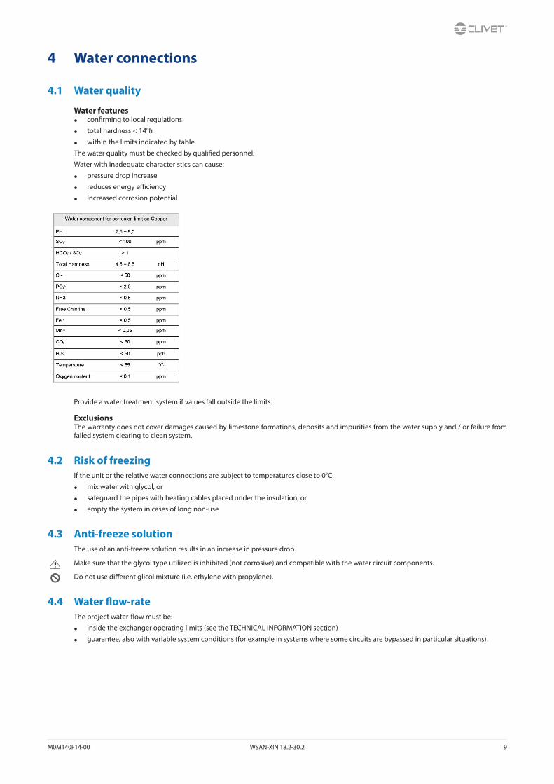
Water features• confirming to local regulations
• total hardness < 14°fr
• within the limits indicated by table
The water quality must be checked by qualified personnel.
Water with inadequate characteristics can cause:
• pressure drop increase
• reduces energy efficiency
• increased corrosion potential
Provide a water treatment system if values fall outside the limits.
ExclusionsThe warranty does not cover damages caused by limestone formations, deposits and impurities from the water supply and / or failure from failed system clearing to clean system.
4.2 Risk of freezingIf the unit or the relative water connections are subject to temperatures close to 0°C:
• mix water with glycol, or
• safeguard the pipes with heating cables placed under the insulation, or
• empty the system in cases of long non-use
4.3 Anti-freeze solutionThe use of an anti-freeze solution results in an increase in pressure drop.
Make sure that the glycol type utilized is inhibited (not corrosive) and compatible with the water circuit components.
Do not use different glicol mixture (i.e. ethylene with propylene).
4.4 Water flow-rateThe project water-flow must be:
• inside the exchanger operating limits (see the TECHNICAL INFORMATION section)
• guarantee, also with variable system conditions (for example in systems where some circuits are bypassed in particular situations).
10 WSAN-XIN 18.2-30.2 M0M140F14-00
4.5 Operation sequenceClose all drain valves in the low points of the unit hydraulic circuit:
• Heat exchangers
• Pumps
• collectors
• storage tank
• free-cooling coil
1. Carefully wash the system with clean water: fill and drain the system several times.
2. Apply additives to prevent corrosion, fouling, formation of mud and algae.
3. Fill the plant
4. Execute leakage test.
5. Isolate the pipes to avoid heat dispersions and formation of condensate.
6. Leave various point of service free (wells, vent-holes etc).
Neglecting the washing will lead to several filter cleaning interventions and at worst cases can cause damages to the exchangers and the other parts.
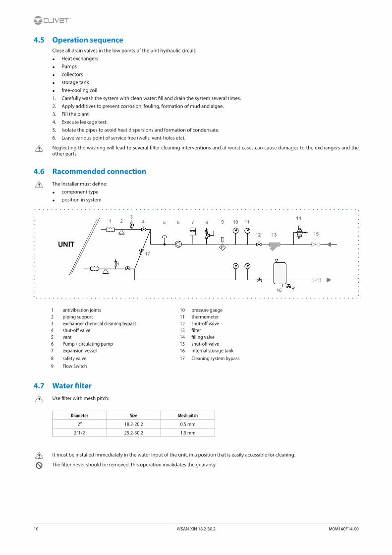
4.6 Racommended connectionThe installer must define:
• component type
• position in system
1 antivibration joints 10 pressure gauge2 piping support 11 thermometer3 exchanger chemical cleaning bypass 12 shut-off valve4 shut-off valve 13 filter5 vent 14 filling valve6 Pump / circulating pump 15 shut-off valve7 expansion vessel 16 Internal storage tank8 safety valve 17 Cleaning system bypass9 Flow Switch
4.7 Water filterUse filter with mesh pitch:
Diameter Size Mesh pitch
2” 18.2-20.2 0,5 mm
2”1/2 25.2-30.2 1,5 mm
It must be installed immediately in the water input of the unit, in a position that is easily accessible for cleaning.
The filter never should be removed, this operation invalidates the guaranty.
M0M140F14-00 WSAN-XIN 18.2-30.2 11
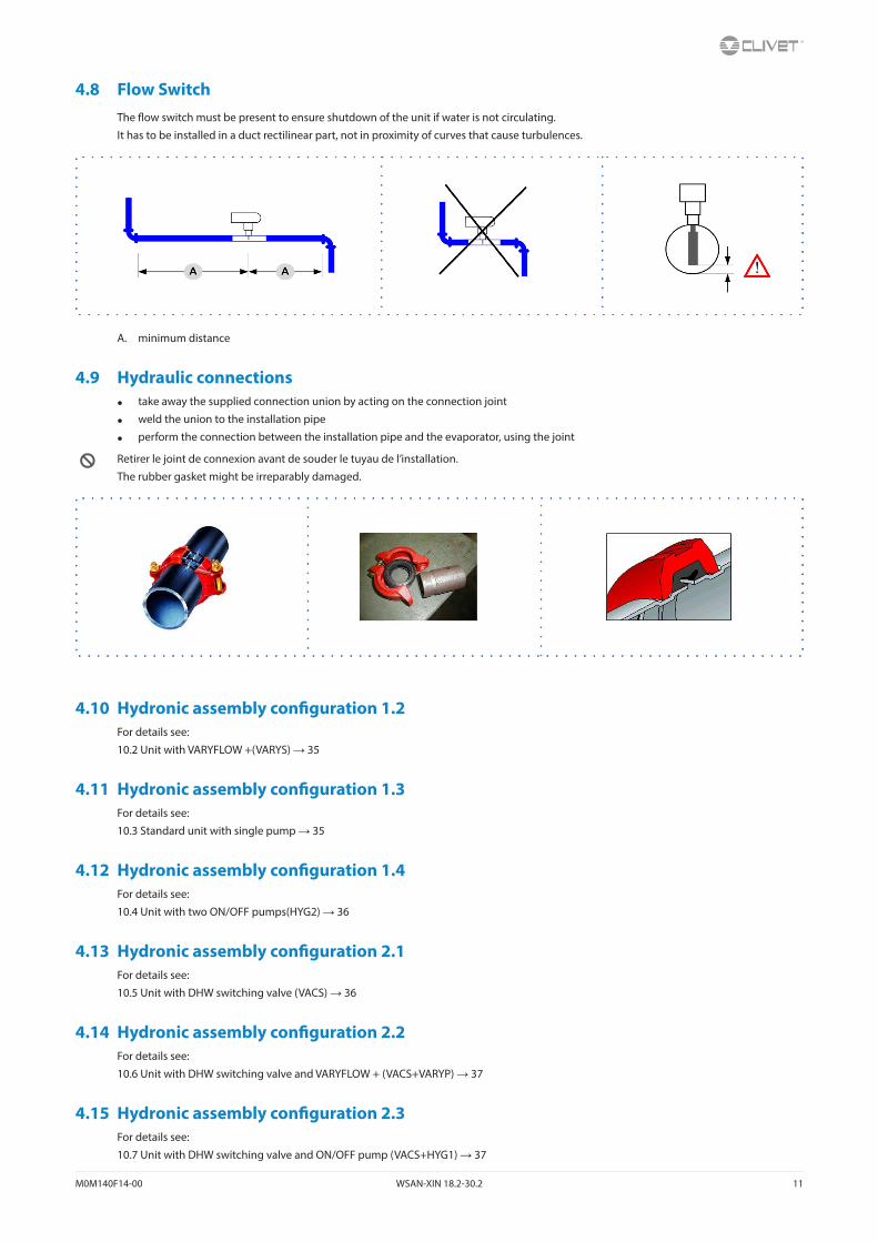
4.8 Flow SwitchThe flow switch must be present to ensure shutdown of the unit if water is not circulating.
It has to be installed in a duct rectilinear part, not in proximity of curves that cause turbulences.
A. minimum distance
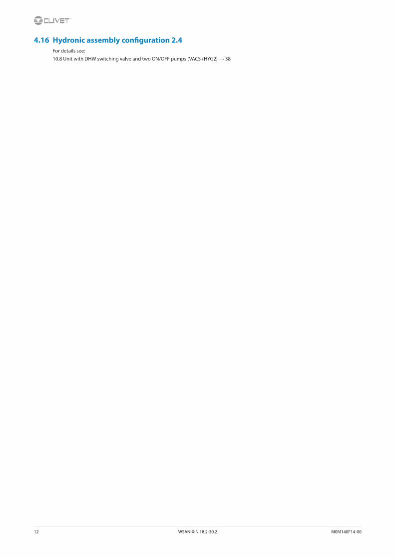
4.9 Hydraulic connections• take away the supplied connection union by acting on the connection joint
• weld the union to the installation pipe
• perform the connection between the installation pipe and the evaporator, using the joint
Retirer le joint de connexion avant de souder le tuyau de l’installation.
The rubber gasket might be irreparably damaged.
4.10 Hydronic assembly configuration 1.2For details see:
10.2 Unit with VARYFLOW +(VARYS) → 35
4.11 Hydronic assembly configuration 1.3For details see:
10.3 Standard unit with single pump → 35
4.12 Hydronic assembly configuration 1.4For details see:
10.4 Unit with two ON/OFF pumps(HYG2) → 36
4.13 Hydronic assembly configuration 2.1For details see:
10.5 Unit with DHW switching valve (VACS) → 36
4.14 Hydronic assembly configuration 2.2For details see:
10.6 Unit with DHW switching valve and VARYFLOW + (VACS+VARYP) → 37
4.15 Hydronic assembly configuration 2.3For details see:
10.7 Unit with DHW switching valve and ON/OFF pump (VACS+HYG1) → 37
12 WSAN-XIN 18.2-30.2 M0M140F14-00
4.16 Hydronic assembly configuration 2.4For details see:
10.8 Unit with DHW switching valve and two ON/OFF pumps (VACS+HYG2) → 38
M0M140F14-00 WSAN-XIN 18.2-30.2 13
5 Electrical connectionsThe characteristics of the electrical lines must be determined by qualified electrica personnel able to design electrical installations; moreover, the lines must be in conformity with regulations in force.
The protection devices of the unit power line must be able to stop all short circuit current, the value must be determined in accordance with system features.
The power cables and the protection cable section must be defined in accordance with the characteristics of the protections adopted.
All electrical operations should be performed by trained personnel having the necessary qualifications required by the regulations in force and being informed about the risks relevant to these activities.
Operate in compliance with safety regulations in force.
5.1 Electrical dateThe serial number label reports the unit specific electrical data, included any electrical accessories.
The electrical data indicated in the technical bulletin and in the manual refer to the standard unit, accessories excluded.
The matriculation plate shows the indications foreseen by the standards, in particular:
• Voltage
• F.L.A.: full load ampere, absorbed current at maximum admitted conditions
• F.L.I.: full load input, full load power input at max. admissible condition
• Electrical wiringdiagram Nr.
5.2 Connections1. Refer to the unit electrical diagram (the number of the diagram is shown on the serial number label).
2. Verify that the electrical supply has characteristics conforming to the data shown on the serial number label.
3. Before starting work, ensure the unit is isolated, unable to be turned on and a safety sign used.
4. Ensure correct earth connection.
5. Ensure cables are suitably protected.
6. Before powering up the unit, make sure that all the protections that were removed during the electrical connection work have been restored.
5.3 Signals / data linesDo not exceed the maximum power allowed, which varies, according to the type of signal.
Lay the cables far from power cables or cables having a different tension and that are able to emit electromagnetic disturbances.
Do not lay the cable near devices which can generate electromagnetic interferences.
Do not lay the cables parallel to other cables, cable crossings are possible, only if laid at 90°.
Connect the screen to the ground, only if there aren’t disturbances.
Guarantee the continuity of the screen during the entire extension of the cable.
Respect impendency, capacity and attenuation indications.
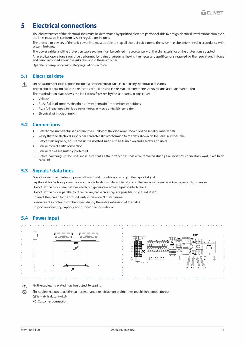
5.4 Power input
Fix the cables: if vacated may be subject to tearing.
The cable must not touch the compressor and the refrigerant piping (they reach high temparatures).
QS1: main isolator switch
XC: Customer connections
14 WSAN-XIN 18.2-30.2 M0M140F14-00
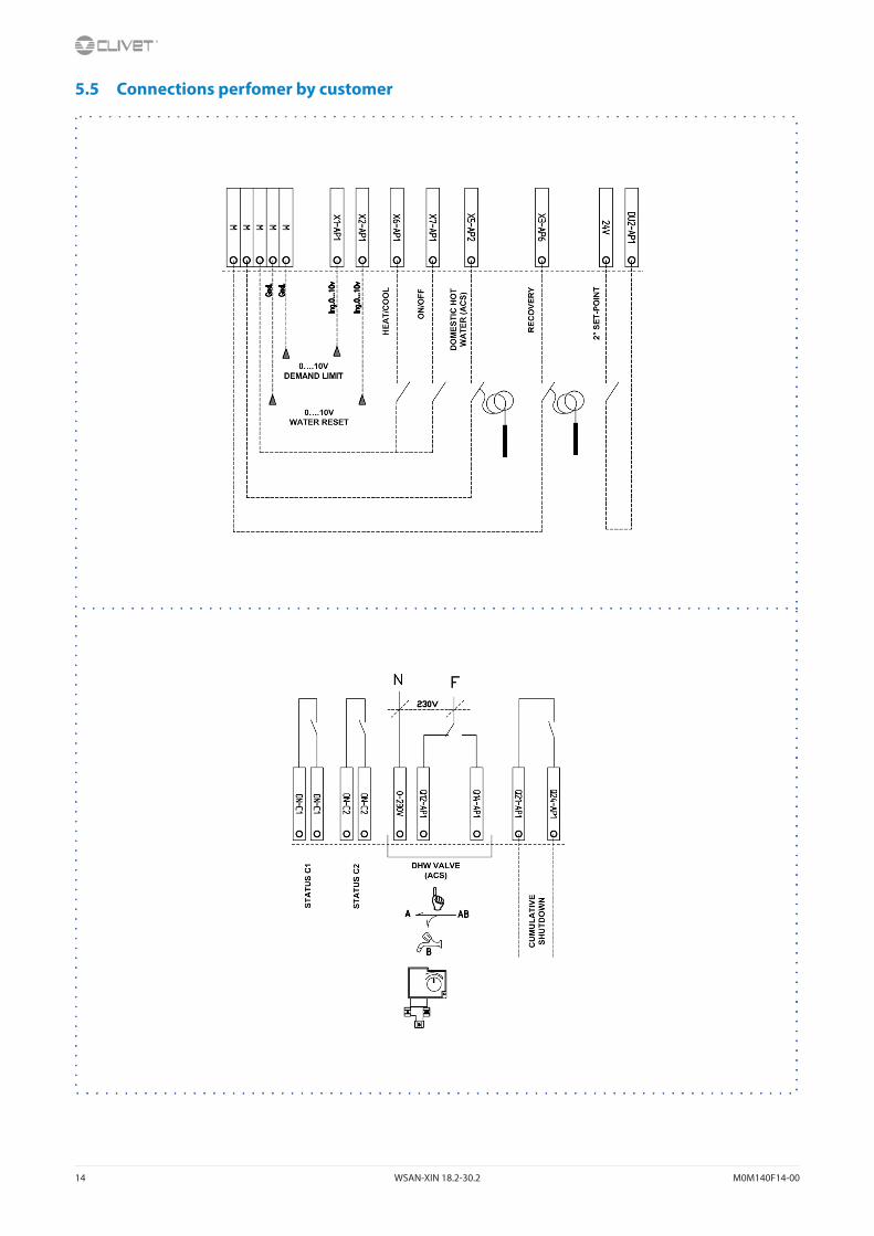
5.5 Connections perfomer by customer
M0M140F14-00 WSAN-XIN 18.2-30.2 15
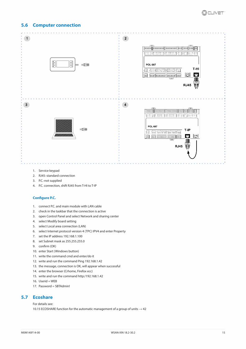
5.6 Computer connection
1. Service keypad
2. RJ45: standard connection
3. P.C.-not supplied
4. P.C. connection, shift RJ45 from T-HI to T-IP
Configure P.C.
1. connect P.C. and main module with LAN cable
2. check in the taskbar that the connection is active
3. open Control Panel and select Network and sharing center
4. select Modify board setting
5. select Local area connection (LAN)
6. select Internet protocol version 4 (TPC) IPV4 and enter Property
7. set the IP address 192.168.1.100
8. set Subnet mask as 255.255.255.0
9. confirm (OK)
10. enter Start (Windows button)
11. write the command cmd and enter/do it
12. write and run the command Ping 192.168.1.42
13. the message, connection is OK, will appear when successful
14. enter the browser (Crhome, Firefox ecc)
15. write and run the command http:/192.168.1.42
16. Userid = WEB
17. Password = SBTAdmin!
5.7 EcoshareFor details see:
10.15 ECOSHARE function for the automatic management of a group of units → 42

16 WSAN-XIN 18.2-30.2 M0M140F14-00
6 Start-up
6.1 General descriptionThe indicated operations should be done by qualified technician with specific training on the product.
Upon request, the service centres performing the start-up.
The electrical, water connections and the other system works are by the installer.
Agree upon in advance the star-up data with the service centre.
Before checking, please verify the following:
• the unit should be installed properly and in conformity with this manual
• the electrical power supply line should be isolated at the beginning
• the unit isolator is open, locked and equipped with the suitable warning
• make sure no tension is present
After turning off the power, wait at least 5 minutes before accessing to the electrical panel or any other electrical component.
Before accessing check with a multimeter that there are no residual stresses.
6.2 Preliminary checksFor details refer to the different manual sections.
Unit OFF power supply1. safety access
2. functional spaces
3. air flow: correct return and supply (no bypass, no stratification)
4. structure integrity
5. fans run freely
6. unit on vibration isolators
7. unit input water filter + shut-off valves for cleaning
8. vibration isolators on water connections
9. expansion tank (indicative volume = 5% system content)
10. Close all drain valves in the low points of the unit hydraulic circuit:
11. cleaned system
12. loaded system + possible glycol solution + corrosion inhibitor
13. system under pressure
14. vented system
15. fresh air probe
16. refrigerant circuit visual check
17. earthing connection
18. power supply features
19. electrical connections provided by the customer
6.3 Start-up sequenceFor details refer to the different manual sections.
Unit ON power supply1. compressor crankcase heaters operating at least since 8 hours
2. off-load voltage measure
3. phase sequence check
4. pump manual start-up and flow check
5. shut-off valve refrigerant circuit open
6. unit ON
7. load voltage measure and absorptions
8. liquid sight glass check (no bubbles)
9. check all fan operating
10. measure return and supply water temperature
11. measure super-heating and sub-cooling
12. check no anomalous vibrations are present
13. climatic curve personalization
14. climatic curve personalization
15. scheduling personalization
16. complete and available unit documentation
M0M140F14-00 WSAN-XIN 18.2-30.2 17
6.4 Refrigeration circuit1. Check carefully the refrigerating circuit: the presence of oil stains can mean leakage caused by transportation, movements or other).
2. Verify that the refrigerating circuit is in pressure: Using the unit manometers, if present, or service manometers.
3. Make sure that all the service outlets are closed with proper caps; if caps are not present a leak of refrigerant can be possible.
4. Open the valves of the refrigerant circuit, if there are any.
6.5 Water circuit1. Before realizing the unit connection make sure that the hydraulic system has been cleaned up and the cleaning water has been drained.
2. Check that the water circuit has been filled and pressurized.
3. Check that the shut-off valves in the circuit are in the “OPEN” position.
4. Check that there isn’t air in the circuit, if required, evacuate it using the air bleed valve placed in the system high points.
5. When using antifreeze solutions, make sure the glycol percentage is suitable for the type of use envisaged.
Weight of glycol (%) 10 20 30 40
Freezing temperature (°C) -3.9 -8.9 -15.6 -23.4
Safety temperature (°C) -1 -4 -10 -19
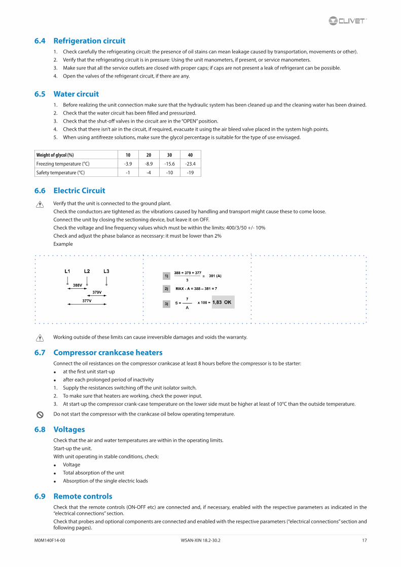
6.6 Electric CircuitVerify that the unit is connected to the ground plant.
Check the conductors are tightened as: the vibrations caused by handling and transport might cause these to come loose.
Connect the unit by closing the sectioning device, but leave it on OFF.
Check the voltage and line frequency values which must be within the limits: 400/3/50 +/- 10%
Check and adjust the phase balance as necessary: it must be lower than 2%
Example
Working outside of these limits can cause irreversible damages and voids the warranty.
6.7 Compressor crankcase heatersConnect the oil resistances on the compressor crankcase at least 8 hours before the compressor is to be starter:
• at the first unit start-up
• after each prolonged period of inactivity
1. Supply the resistances switching off the unit isolator switch.
2. To make sure that heaters are working, check the power input.
3. At start-up the compressor crank-case temperature on the lower side must be higher at least of 10°C than the outside temperature.
Do not start the compressor with the crankcase oil below operating temperature.
6.8 VoltagesCheck that the air and water temperatures are within in the operating limits.
Start-up the unit.
With unit operating in stable conditions, check:
• Voltage
• Total absorption of the unit
• Absorption of the single electric loads
6.9 Remote controlsCheck that the remote controls (ON-OFF etc) are connected and, if necessary, enabled with the respective parameters as indicated in the “electrical connections” section.
Check that probes and optional components are connected and enabled with the respective parameters (“electrical connections” section and following pages).
18 WSAN-XIN 18.2-30.2 M0M140F14-00
6.10 Demand limitMenu accessible only after having entered the password.
Access reserved only to specifically trained personnel.
The parameter modification can cause irreversible damages.
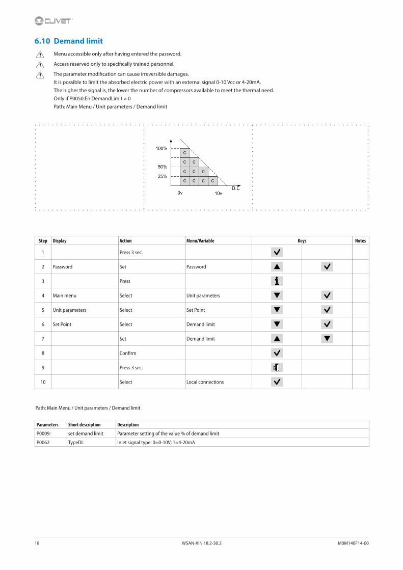
It is possible to limit the absorbed electric power with an external signal 0-10 Vcc or 4-20mA.
The higher the signal is, the lower the number of compressors available to meet the thermal need.
Only if P0050:En DemandLimit ≠ 0
Path: Main Menu / Unit parameters / Demand limit
Step Display Action Menu/Variable Keys Notes
1 Press 3 sec.
2 Password Set Password
3 Press
4 Main menu Select Unit parameters
5 Unit parameters Select Set Point
6 Set Point Select Demand limit
7 Set Demand limit
8 Confirm
9 Press 3 sec.
10 Select Local connections
Path: Main Menu / Unit parameters / Demand limit
Parameters Short description Description
P0009: set demand limit Parameter setting of the value % of demand limit
P0062 TypeDL Inlet signal type: 0=0-10V; 1=4-20mA
M0M140F14-00 WSAN-XIN 18.2-30.2 19
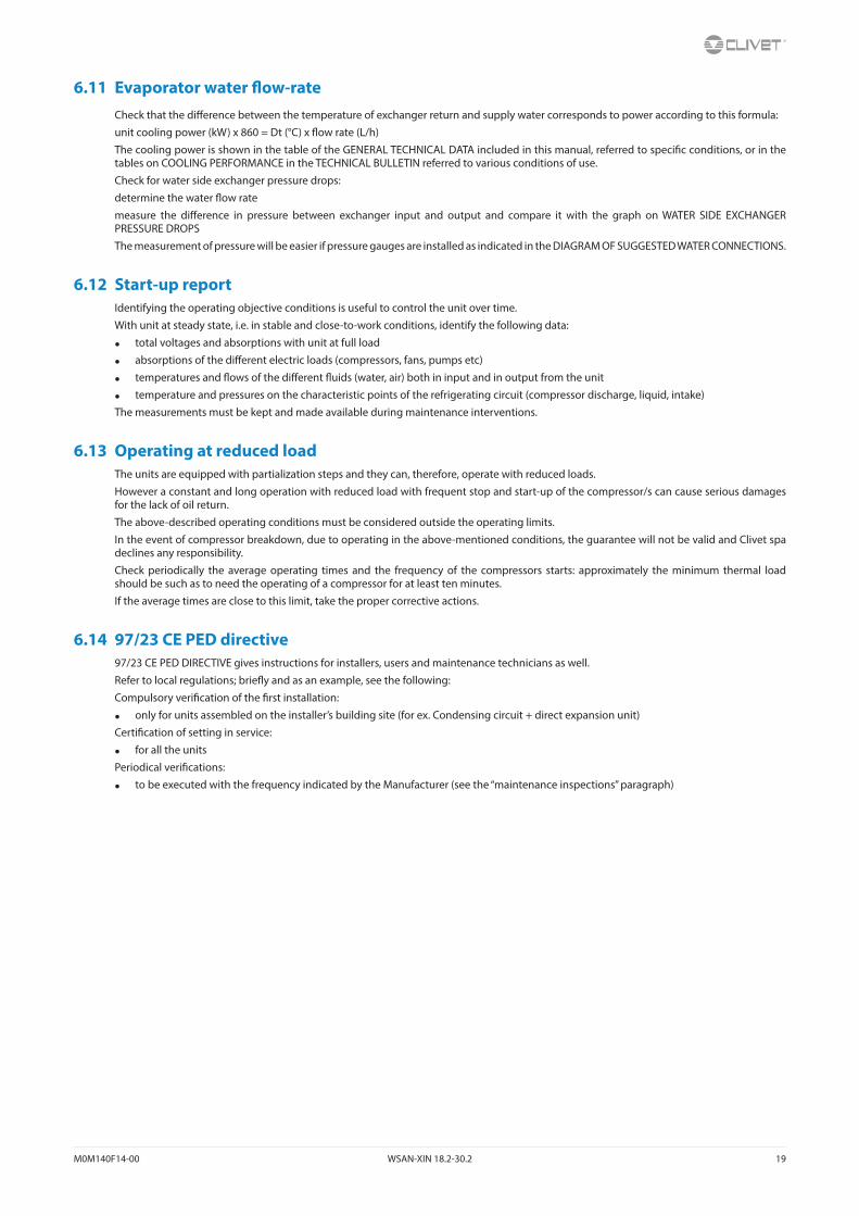
6.11 Evaporator water flow-rateCheck that the difference between the temperature of exchanger return and supply water corresponds to power according to this formula:
unit cooling power (kW) x 860 = Dt (°C) x flow rate (L/h)
The cooling power is shown in the table of the GENERAL TECHNICAL DATA included in this manual, referred to specific conditions, or in the tables on COOLING PERFORMANCE in the TECHNICAL BULLETIN referred to various conditions of use.
Check for water side exchanger pressure drops:
determine the water flow rate
measure the difference in pressure between exchanger input and output and compare it with the graph on WATER SIDE EXCHANGER PRESSURE DROPS
The measurement of pressure will be easier if pressure gauges are installed as indicated in the DIAGRAM OF SUGGESTED WATER CONNECTIONS.
6.12 Start-up reportIdentifying the operating objective conditions is useful to control the unit over time.
With unit at steady state, i.e. in stable and close-to-work conditions, identify the following data:
• total voltages and absorptions with unit at full load
• absorptions of the different electric loads (compressors, fans, pumps etc)
• temperatures and flows of the different fluids (water, air) both in input and in output from the unit
• temperature and pressures on the characteristic points of the refrigerating circuit (compressor discharge, liquid, intake)
The measurements must be kept and made available during maintenance interventions.
6.13 Operating at reduced loadThe units are equipped with partialization steps and they can, therefore, operate with reduced loads.
However a constant and long operation with reduced load with frequent stop and start-up of the compressor/s can cause serious damages for the lack of oil return.
The above-described operating conditions must be considered outside the operating limits.
In the event of compressor breakdown, due to operating in the above-mentioned conditions, the guarantee will not be valid and Clivet spa declines any responsibility.
Check periodically the average operating times and the frequency of the compressors starts: approximately the minimum thermal load should be such as to need the operating of a compressor for at least ten minutes.
If the average times are close to this limit, take the proper corrective actions.
6.14 97/23 CE PED directive97/23 CE PED DIRECTIVE gives instructions for installers, users and maintenance technicians as well.
Refer to local regulations; briefly and as an example, see the following:
Compulsory verification of the first installation:
• only for units assembled on the installer’s building site (for ex. Condensing circuit + direct expansion unit)
Certification of setting in service:
• for all the units
Periodical verifications:
• to be executed with the frequency indicated by the Manufacturer (see the “maintenance inspections” paragraph)

20 WSAN-XIN 18.2-30.2 M0M140F14-00
7 Control
7.1 LedINFO Not used
ALARM Blink / fixed = alarm present
CANCEL not used currently
7.2 DisplayRef. Variable Description
A Date - Time
B ActualSetPoint Temperature setting
C T.InH2OUtilitySide Water inlet temperature utility side
D T.OutH2OUtilitySide Water outlet temperature utility side
E ActualState On / off / eco / pmp On
F ActualMode Cool: water coolingHeat: Heating (not used)
2 Installed compressors
1 - 0Compressors ONexample: circuit 1 = 1 compr. Oncircuit 2 = 0 compr. On
50% Heating capacity
7.3 KeysSymbol Name Description
Info Main menu
Alarm Alarm display
CancelExitPrevious levelKeyboard settings
Up Increases value
Down Decreases value
Enter ConfirmPassword
M0M140F14-00 WSAN-XIN 18.2-30.2 21
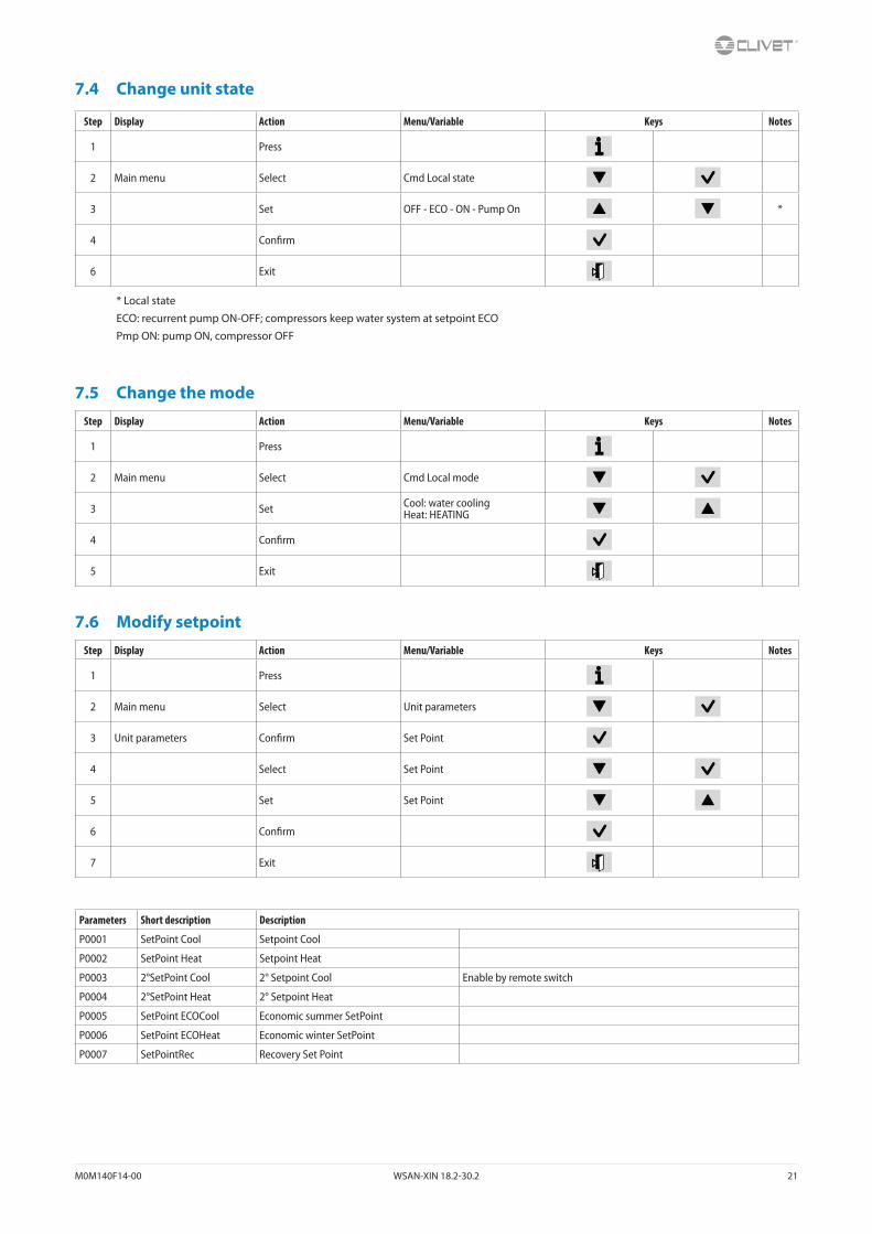
7.4 Change unit state
Step Display Action Menu/Variable Keys Notes
1 Press
2 Main menu Select Cmd Local state
3 Set OFF - ECO - ON - Pump On *
4 Confirm
6 Exit
* Local state
ECO: recurrent pump ON-OFF; compressors keep water system at setpoint ECO
Pmp ON: pump ON, compressor OFF
7.5 Change the modeStep Display Action Menu/Variable Keys Notes
1 Press
2 Main menu Select Cmd Local mode
3 Set Cool: water coolingHeat: HEATING
4 Confirm
5 Exit
7.6 Modify setpointStep Display Action Menu/Variable Keys Notes
1 Press
2 Main menu Select Unit parameters
3 Unit parameters Confirm Set Point
4 Select Set Point
5 Set Set Point
6 Confirm
7 Exit
Parameters Short description Description
P0001 SetPoint Cool Setpoint Cool
P0002 SetPoint Heat Setpoint Heat
P0003 2°SetPoint Cool 2° Setpoint Cool Enable by remote switch
P0004 2°SetPoint Heat 2° Setpoint Heat
P0005 SetPoint ECOCool Economic summer SetPoint
P0006 SetPoint ECOHeat Economic winter SetPoint
P0007 SetPointRec Recovery Set Point
22 WSAN-XIN 18.2-30.2 M0M140F14-00
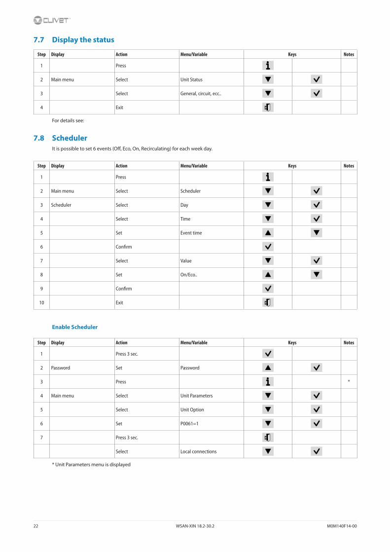
7.7 Display the status
Step Display Action Menu/Variable Keys Notes
1 Press
2 Main menu Select Unit Status
3 Select General, circuit, ecc..
4 Exit
For details see:
7.8 SchedulerIt is possible to set 6 events (Off, Eco, On, Recirculating) for each week day.
Step Display Action Menu/Variable Keys Notes
1 Press
2 Main menu Select Scheduler
3 Scheduler Select Day
4 Select Time
5 Set Event time
6 Confirm
7 Select Value
8 Set On/Eco..
9 Confirm
10 Exit
Enable Scheduler
Step Display Action Menu/Variable Keys Notes
1 Press 3 sec.
2 Password Set Password
3 Press *
4 Main menu Select Unit Parameters
5 Select Unit Option
6 Set P0061=1
7 Press 3 sec.
Select Local connections
* Unit Parameters menu is displayed

M0M140F14-00 WSAN-XIN 18.2-30.2 23
7.9 Alarms
Before resetting an alarm identify and remove its cause.
Repeated resets can cause irreversible damage.
Example:
+ eE001: Monitore fase: Fault = active alarm
- EE003: Guasto P1 Util: Ok = resetted alarm
Display of alarm: step 1-3
Reset allarm: step 4-10
Step Display Action Menu/Variable Keys Notes
1 Press
2 Alarm list detail Press
3 Alarm list Select Alarm
4 Alarm list detail Press 3 sec.
5 Password Set Enter password
6 Alarm list detail Press
7 Alarm list Select Alarm
8 Select ResetExecuted
9 Press 3 sec.
10 Password management Select Log off
For details see:
7.10 Keyboard settingsStep Display Action Menu/Variable Keys Notes
1 Press 3 sec.
2 Press
3 HMI Settings Select
4 Press
5 Press
6 Select Local connections
24 WSAN-XIN 18.2-30.2 M0M140F14-00
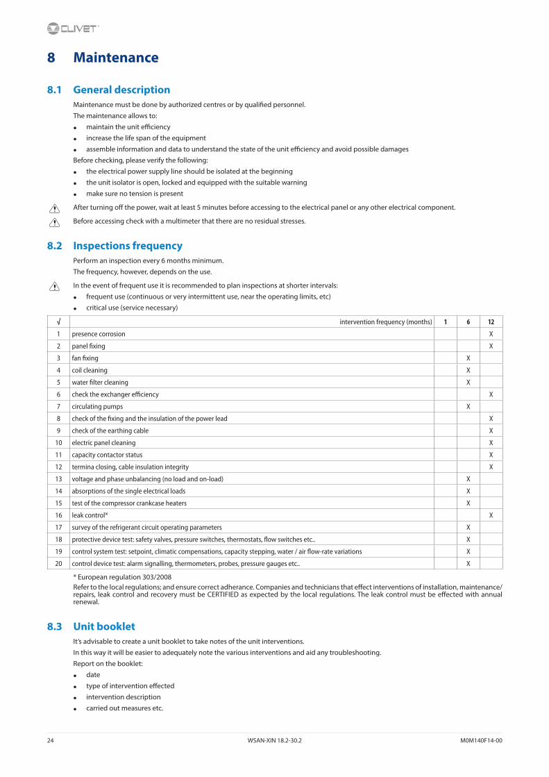
8 Maintenance
8.1 General descriptionMaintenance must be done by authorized centres or by qualified personnel.
The maintenance allows to:
• maintain the unit efficiency
• increase the life span of the equipment
• assemble information and data to understand the state of the unit efficiency and avoid possible damages
Before checking, please verify the following:
• the electrical power supply line should be isolated at the beginning
• the unit isolator is open, locked and equipped with the suitable warning
• make sure no tension is present
After turning off the power, wait at least 5 minutes before accessing to the electrical panel or any other electrical component.
Before accessing check with a multimeter that there are no residual stresses.
8.2 Inspections frequencyPerform an inspection every 6 months minimum.
The frequency, however, depends on the use.
In the event of frequent use it is recommended to plan inspections at shorter intervals:
• frequent use (continuous or very intermittent use, near the operating limits, etc)
• critical use (service necessary)
√ intervention frequency (months) 1 6 12
1 presence corrosion X
2 panel fixing X
3 fan fixing X
4 coil cleaning X
5 water filter cleaning X
6 check the exchanger efficiency X
7 circulating pumps X
8 check of the fixing and the insulation of the power lead X
9 check of the earthing cable X
10 electric panel cleaning X
11 capacity contactor status X
12 termina closing, cable insulation integrity X
13 voltage and phase unbalancing (no load and on-load) X
14 absorptions of the single electrical loads X
15 test of the compressor crankcase heaters X
16 leak control* X
17 survey of the refrigerant circuit operating parameters X
18 protective device test: safety valves, pressure switches, thermostats, flow switches etc.. X
19 control system test: setpoint, climatic compensations, capacity stepping, water / air flow-rate variations X
20 control device test: alarm signalling, thermometers, probes, pressure gauges etc.. X
* European regulation 303/2008Refer to the local regulations; and ensure correct adherance. Companies and technicians that effect interventions of installation, maintenance/repairs, leak control and recovery must be CERTIFIED as expected by the local regulations. The leak control must be effected with annual renewal.
8.3 Unit bookletIt’s advisable to create a unit booklet to take notes of the unit interventions.
In this way it will be easier to adequately note the various interventions and aid any troubleshooting.
Report on the booklet:
• date
• type of intervention effected
• intervention description
• carried out measures etc.

M0M140F14-00 WSAN-XIN 18.2-30.2 25
8.4 Standby modeIf a long period of inactivity is foreseen:
• turn off the power
• avoid the risk of frost (empty the system or add glycol)
Turn off the power to avoid electrical risks or damages by lightning strikes.
With lower temperatures keep heaters turned on in of the electrical panel (option).
It’s recommended that the re-start after the stopping period is performed by a qualified technician, especially after seasonal stops or seasonal switching.
When restarting, refer to what is indicated in the “start-up” section.
Schedule technical assistance in advance to avoid hitches and to guarantee that the system can be used when required.
8.5 Water side exchangerIt is very important for the exchanger to be able to provide the maximum thermal exchange, therefore it is essential for the inner surfaces to be clean of dirt and incrustations.
Periodically check the difference between the temperature of the supply water and the condensation temperature: if the difference is greater than 8°C–10°C it is advisable to clean the exchanger.
The clearing must be effected:
• with circulation opposite to the usual one
• with a speed at least 1,5 times higher than the nominal one
• with an appropriate product moderately acid (95% water + 5% phosphoric acid)
• after the cleaning rinse with water to inhibit the action of any residual product
8.6 Water filterCheck that no impurities prevent the correct passage of water.
8.7 Circulating pumpsCheck:
• no leaks
• bearing status (anomalies are highlighted by abnormal noise and vibration)
• the terminal protection covers are closed and the cable holders are properly positioned
8.8 Flow Switch• controls the operations
• remove incrustations from the palette
8.9 Electric fansCheck:
• the fans and the relative protection gridsare well fixed
• the fan bearings (evident by noise and anomalous vibrations)
• the terminal protection covers are closed and the cable holders are properly positioned
8.10 Air coilContact with the exchanger fins can cause cuts: wear protective gloves to perform the above described operations.
It is extremely important that the battery gives the maximum thermal exchange; therefore, its surface must be cleaned from dust and deposits.
Remove all impurities from the surface.
Using an air pressure gun, clean the aluminum surface of the battery; be careful to direct the air in the opposite direction of the fan air movement.
Hold the gun parallel to the fins to avoid damages.
As an alternative, vacumn cleaner can be used to suck impurities from the air input side.
Verify that the aluminum fins are not bent or damaged, in the event of damages contact the authorized assistance center and get the fins straightened in order to restore the initial condition for an optimal air flow.

26 WSAN-XIN 18.2-30.2 M0M140F14-00
8.11 Compressor supply line shut-off valve
A. Supply line shut-off valve
CAUTION!
Do not remove the seal
Remove only if authorized by the manufacturer.
Please contact the maker for informations.
8.12 System discharge1. evacuate the system
2. open all drain valves in the low points of the unit hydraulic circuit
3. evacuate the exchanger, use all the cocks presents
4. use compressed air to blow the exchanger
5. dry completely the exchanger by an hot air jet; for greater safety fill the exchanger with glycoled solution
6. protect the exchanger from the air
7. remove the drain plugs to the pumps
Any anti-freeze liquid contained in the system should not be discharged freely as it is a pollutant.
It must be collected and reused.
Before starting a washing the plant.
Example
• emptying pump
It’s recommended that the re-start after the stopping period is performed by a qualified technician, especially after seasonal stops or seasonal switching.
When restarting, refer to what is indicated in the “start-up” section.
Schedule technical assistance in advance to avoid hitches and to guarantee that the system can be used when required.

M0M140F14-00 WSAN-XIN 18.2-30.2 27
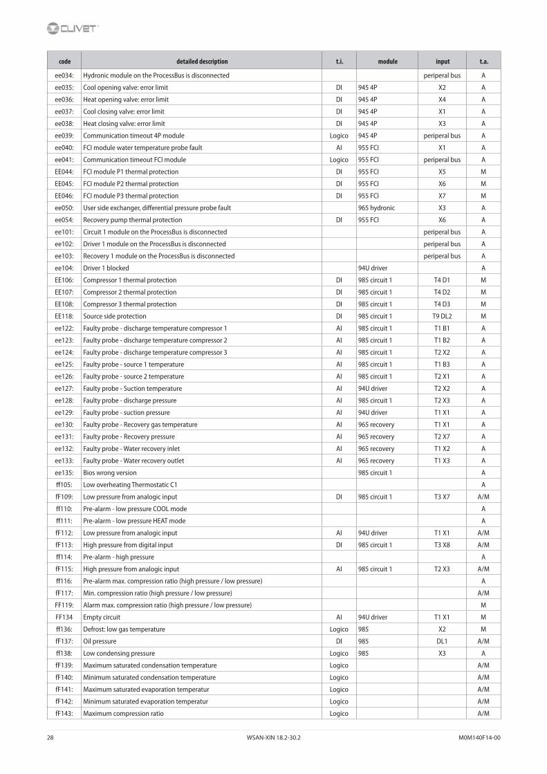
9 Alarms - Status
9.1 Alarms
The alarm code identifies the concerned circuit:
Example:
ee 1 01:TimeOutModCirc = circuit 1
ee 2 01:TimeOutModCirc = circuit 2
The number of refrigerant circuits depends on series and size of the unit.
t.i. input type:DI = digital input
AI = analogic input
Module:687 = main module
985 = circuit module
94U = thermostatic driver module
Input:Connector number:
T1, T2, T3.....
PIN code:
X1, X2, Q13, DO1.....
t.a. alarm type:A automatic reset
M manual reset
A/M automatic reset, (after N alarm interventions becomes manual reset)
code detailed description t.i. module input t.a.
eE001 Phase monitor DI 687 central T13 DL1 A/M
EE003 Pump 1 overload DI 687 central T13 DL2 M
EE004 Pump 2 overload DI 687 central T4 D1 M
EE005 Pump 3 overload DI 687 central T13 DL2 M
ee010 Master Offline - Master Slave network enabled A
ee011 Unit 2 in alarm - Master Slave network enabled A
ee012 Unit 2 OffLine - Master Slave network enabled A
ee013 Unit 3 in alarm - Master Slave network enabled A
ee014 Unit 3 OffLine - Master Slave network enabled A
ee015 Unit 4 in alarm - Master Slave network enabled A
ee016 Unit 4 OffLine - Master Slave network enabled A
ee017 Unit 5 in alarm - Master Slave network enabled A
ee018 Unit 5 OffLine - Master Slave network enabled A
ee019 Unit 6 in alarm - Master Slave network enabled A
ee020 Unit 6 OffLine - Master Slave network enabled A
ee021 Unit 7 in alarm - Master Slave network enabled A
ee022 Unit 7 OffLine - Master Slave network enabled A
EE023 Pump 1 thermal protection DI 965 hydronic T1 X4 M
EE024 Pump 2 thermal protection DI 965 hydronic T1 X5 M
EE025 Pump 3 thermal protection DI 965 hydronic T1 X6 A
EE026 Inverter thermal protection DI 965 hydronic T5 DL1 A
ee027 Water inlet temperature probe faulty AI 687 central T1 B1 A
ee028 Water outlet temperature probe faulty AI 687 central T1 B2 A
ee029 External air temperature probe faulty AI 687 central T1 B3 A
ee030 Signal logoff or short circuit AI 687 central T2 X1 A
ee031 Signal logoff or short circuit AI 687 central T2 X2 A
ee032: External Humidity probe faulty AI 687 central T2 X3 A
ee033: Cabinet temperature probe faulty AI 687 central T2 X4 A
28 WSAN-XIN 18.2-30.2 M0M140F14-00
code detailed description t.i. module input t.a.
ee034: Hydronic module on the ProcessBus is disconnected periperal bus A
ee035: Cool opening valve: error limit DI 945 4P X2 A
ee036: Heat opening valve: error limit DI 945 4P X4 A
ee037: Cool closing valve: error limit DI 945 4P X1 A
ee038: Heat closing valve: error limit DI 945 4P X3 A
ee039: Communication timeout 4P module Logico 945 4P periperal bus A
ee040: FCI module water temperature probe fault AI 955 FCI X1 A
ee041: Communication timeout FCI module Logico 955 FCI periperal bus A
EE044: FCI module P1 thermal protection DI 955 FCI X5 M
EE045: FCI module P2 thermal protection DI 955 FCI X6 M
EE046: FCI module P3 thermal protection DI 955 FCI X7 M
ee050: User side exchanger, differential pressure probe fault 965 hydronic X3 A
ee054: Recovery pump thermal protection DI 955 FCI X6 A
ee101: Circuit 1 module on the ProcessBus is disconnected periperal bus A
ee102: Driver 1 module on the ProcessBus is disconnected periperal bus A
ee103: Recovery 1 module on the ProcessBus is disconnected periperal bus A
ee104: Driver 1 blocked 94U driver A
EE106: Compressor 1 thermal protection DI 985 circuit 1 T4 D1 M
EE107: Compressor 2 thermal protection DI 985 circuit 1 T4 D2 M
EE108: Compressor 3 thermal protection DI 985 circuit 1 T4 D3 M
EE118: Source side protection DI 985 circuit 1 T9 DL2 M
ee122: Faulty probe - discharge temperature compressor 1 AI 985 circuit 1 T1 B1 A
ee123: Faulty probe - discharge temperature compressor 2 AI 985 circuit 1 T1 B2 A
ee124: Faulty probe - discharge temperature compressor 3 AI 985 circuit 1 T2 X2 A
ee125: Faulty probe - source 1 temperature AI 985 circuit 1 T1 B3 A
ee126: Faulty probe - source 2 temperature AI 985 circuit 1 T2 X1 A
ee127: Faulty probe - Suction temperature AI 94U driver T2 X2 A
ee128: Faulty probe - discharge pressure AI 985 circuit 1 T2 X3 A
ee129: Faulty probe - suction pressure AI 94U driver T1 X1 A
ee130: Faulty probe - Recovery gas temperature AI 965 recovery T1 X1 A
ee131: Faulty probe - Recovery pressure AI 965 recovery T2 X7 A
ee132: Faulty probe - Water recovery inlet AI 965 recovery T1 X2 A
ee133: Faulty probe - Water recovery outlet AI 965 recovery T1 X3 A
ee135: Bios wrong version 985 circuit 1 A
ff105: Low overheating Thermostatic C1 A
fF109: Low pressure from analogic input DI 985 circuit 1 T3 X7 A/M
ff110: Pre-alarm - low pressure COOL mode A
ff111: Pre-alarm - low pressure HEAT mode A
fF112: Low pressure from analogic input AI 94U driver T1 X1 A/M
fF113: High pressure from digital input DI 985 circuit 1 T3 X8 A/M
ff114: Pre-alarm - high pressure A
fF115: High pressure from analogic input AI 985 circuit 1 T2 X3 A/M
ff116: Pre-alarm max. compression ratio (high pressure / low pressure) A
fF117: Min. compression ratio (high pressure / low pressure) A/M
FF119: Alarm max. compression ratio (high pressure / low pressure) M
FF134 Empty circuit AI 94U driver T1 X1 M
ff136: Defrost: low gas temperature Logico 985 X2 M
fF137: Oil pressure DI 985 DL1 A/M
ff138: Low condensing pressure Logico 985 X3 A
fF139: Maximum saturated condensation temperature Logico A/M
fF140: Minimum saturated condensation temperature Logico A/M
fF141: Maximum saturated evaporation temperatur Logico A/M
fF142: Minimum saturated evaporation temperatur Logico A/M
fF143: Maximum compression ratio Logico A/M

M0M140F14-00 WSAN-XIN 18.2-30.2 29
code detailed description t.i. module input t.a.
FF144: Minimum compression ratio Logico M
fF145: Maximum engine torque Logico A/M
iI002: Low water pressure DI 687 central T5 DU1 A/M
iI006: Flow switch utility side DI 687 central T3 X8 A/M
II007: Freeze alarm utility side M
ii008: Utility side pumps On for antifreeze alarm A
II009:
COOL:outlet temperature higher than inlet temperatureHEAT:inlet temperature higher than outlet temperature
A
iI120: Flow switch source side DI 985 circuit 1 T2 X4 A/M
II121: Freeze alarm source side A
II042: FCI module, system pressure DI 955 FCI X3 M
II043: FCI module, antifreeze alarm Logico 955 FCI X1 M
ii047: FCI module, water flow alarm DI 955 FCI X4 A
ii052: Recosery module, flow alarm DI 965 REC X6 A
ii053: Recovery module, system pressure DI 965 REC X6 A
9.2 Status
The status code identifies the concerned circuit:
Example:
S 1 100:CMP1 compressor1 starts = circuit 1
S 2 100:CMP1 compressor1 starts = circuit 2
The number of refrigerant circuits depends on series and size of the unit.
Example:
AI-687 T.IN H2OUtil_B1 Inlet water temperatureAI = analogic input
687 = main module
B1 = PIN
9.3 General stata and central module
code description detailed description
AI-687 T.IN H2OUtil_B1 Inlet water temperature utility side
AI-687 T.OUT H2OUtil_B2 Outlet water temperature user side
AI-687 Ext.Air temp_B3 Outdoor air temperature
AI-687 S.DemandLimit_X1 Signal of the demand limit function controls
AI-687 S.WaterReset_X2 Signal of the water reset function controls
AI-687 RHExt_X3 Outside relative humidity
AI-687 El.CabinetTemp_X4 Electrical panel temperature
AO-687 %FREE-COOLING _X5 Percentage value of the status of the external control signal of the ventilation/FREE-COOLING valve
DI-687 Sel.SetPoint_DU2 Status of the second digital input setpoint 0=1°set 1=2°Set
DI-687 SystemPressure_DU1 Status of the system water pressure sensor 0=OK 1=Fault
DI-687 FlowUser_X8 Status of the differential pressure switch/utilisation flow 0=OK 1=Fault
DI-687 ON-OFFRem_X7 Status of the unit status digital input 0=OFF 1=On
DI-687 Heat/CoolRem_X6 Status of the unit mode digital input 0=Heat 1=Cool
DI-687 PhaseMonitor_DL1 Status of the phase monitor input 0=OK 1=Fault
DI-687 OvlP1Util_D2 Status of thermal protection contact of utilisation pump 1 0=OK 1=Fault
DI-687 OvlP2Util_D1 Status of thermal protection contact of utilisation pump 2 0=OK 1=Fault
DI-687 OvlP3Util_DL2 Status of thermal protection contact of utilisation pump 3 0=OK 1=Fault
DO-687 El.CabinetFAN_DO1 Status of the ventilation control of the electrical panel: 0=Off 1=On
DO-687 El.CabinetHEAT_DO2 Status of the heating control of the electrical panel: 0=Off 1=On
DO-687 UnitMode_Q1 Status of the digital output related to the operating mode (N.O. Open=Cool N.O. Closed=Heat): 0=Cool 1=Heat
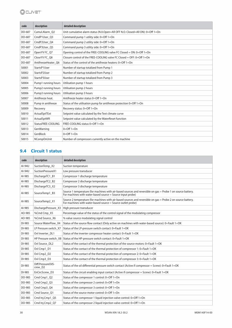
30 WSAN-XIN 18.2-30.2 M0M140F14-00
code description detailed description
DO-687 Cumul.Alarm_Q2 Unit cumulative alarm status (N.0.Open=All OFF N.O. Closed=All ON): 0=Off 1=On
DO-687 CmdP1User_Q3 Command pump 1 utility side: 0=Off 1=On
DO-687 CmdP2User_Q4 Command pump 2 utility side: 0=Off 1=On
DO-687 CmdP3User_Q5 Command pump 3 utility side: 0=Off 1=On
DO-687 OpenYV FC_Q7 Opening control of the FREE-COOLING valve FC Closed = ON: 0=Off 1=On
DO-687 CloseYV FC_Q8 Closure control of the FREE-COOLING valve FC Closed = OFF: 0=Off 1=On
DO-687 AntifreezeHeater_Q6 Status of the control of the antifreeze heaters: 0=Off 1=On
S0001 StartsP1User Number of startup totalized from Pump 1
S0002 StartsP2User Number of startup totalized from Pump 2
S0003 StartsP3User Number of startup totalized from Pump 3
S0004 Pump1 running hours Utilisation pump 1 hours
S0005 Pump2 running hours Utilisation pump 2 hours
S0006 Pump3 running hours Utilisation pump 3 hours
S0007 Antifreeze heat. Antifreeze heater status 0=Off 1=On
S0008 Pump in antifreeze Status of the utilisation pump for antifreeze protection 0=Off 1=On
S0009 Recovery Recovery status: 0=Off 1=On
S0010 ActualSptTExt Setpoint value calculated by the Text climate curve
S0011 ActualSptWR Setpoint value calculated by the WaterReset function
S0012 StatusFREE-COOLING FREE-COOLING status 0=Off 1=On
S0013 GenWarning 0=Off 1=On
S0014 GenBlock 0=Off 1=On
S0015 NCompOnUnit Number of compressors currently active on the machine
9.4 Circuit 1 status
code description detailed description
AI-94U SuctionTemp_X2 Suction temperature
AI-94U SuctionPressureX1 Low pressure transducer
AI-985 DischargeTC1_B1 Compressor 1 discharge temperature
AI-985 DischargeTC2_B2 Compressor 2 discharge temperature
AI-985 DischargeTC3_X2 Compressor 3 discharge temperature
AI-985 SourceTemp1_B3 Source 1 temperature (for machines with air-based sources and reversible on gas = Probe 1 on source battery.For machines with water-based source = Source input probe)
AI-985 SourceTemp2_X1 Source 2 temperature (for machines with air-based sources and reversible on gas = Probe 2 on source battery.For machines with water-based source = Source outlet probe)
AI-985 DischargePressure_X3 High pressure transducer
AO-985 %Cmd Cmp_X5 Percentage value of the status of the control signal of the modulating compressor
AO-985 %Cmd Source_X6 % value source modulating signal control
DI-985 Source WaterFlow_X4 Status of the source flow contact (Only active on machines with water-based source): 0=Fault 1=OK
DI-985 LP Pressure switch_X7 Status of the LP-pressure switch contact: 0=Fault 1=OK
DI-985 Ovl Inverter_DL1 Status of the inverter compressor heater contact: 0=Fault 1=OK
DI-985 HP Pressure switch_X8 Status of the HP-pressure switch contact: 0=Fault 1=OK
DI-985 Ovl Source_DL2 Status of the contact of the thermal protection of the source motors: 0=Fault 1=OK
DI-985 Ovl Cmp1_D1 Status of the contact of the thermal protection of compressor 1: 0=Fault 1=OK
DI-985 Ovl Cmp2_D2 Status of the contact of the thermal protection of compressor 2: 0=Fault 1=OK
DI-985 Ovl Cmp3_D3 Status of the contact of the thermal protection of compressor 3: 0=Fault 1=OK
DI-985 Diff.PressureOilS-crew_D2 Status of the oil differential pressure switch contact (Active if compressor = Screw): 0=Fault 1=OK
DI-985 EnCircScrew_D3 Status of the circuit enabling input contact (Active if compressor = Screw): 0=Fault 1=OK
DO-985 Cmd Cmp1_Q2 Status of the compressor 1 control: 0=Off 1=On
DO-985 Cmd Cmp2_Q3 Status of the compressor 2 control: 0=Off 1=On
DO-985 Cmd Cmp3_Q4 Status of the compressor 3 control: 0=Off 1=On
DO-985 Cmd Source_Q1 Status of the source motor control: 0=Off 1=On
DO-985 Cmd Inj.Cmp1_Q5 Status of the compressor 1 liquid injection valve control: 0=Off 1=On
DO-985 Cmd Inj.Cmp2_Q7 Status of the compressor 2 liquid injection valve control: 0=Off 1=On
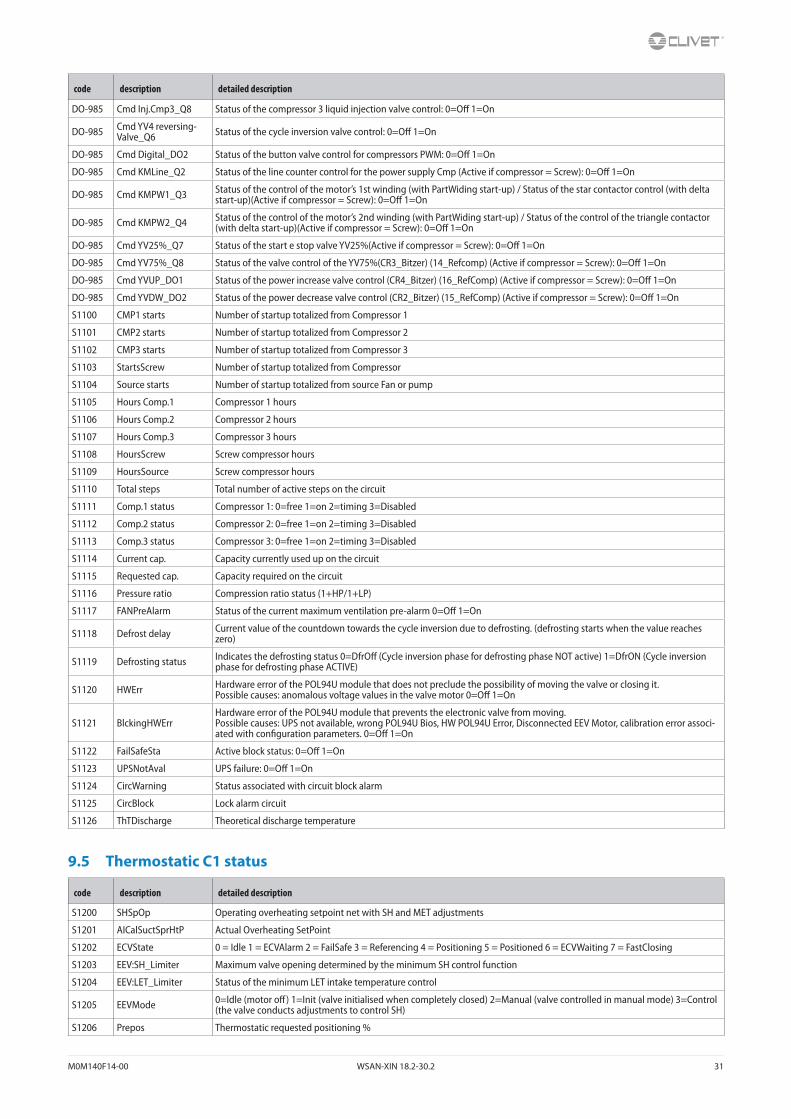
M0M140F14-00 WSAN-XIN 18.2-30.2 31
code description detailed description
DO-985 Cmd Inj.Cmp3_Q8 Status of the compressor 3 liquid injection valve control: 0=Off 1=On
DO-985 Cmd YV4 reversing-Valve_Q6 Status of the cycle inversion valve control: 0=Off 1=On
DO-985 Cmd Digital_DO2 Status of the button valve control for compressors PWM: 0=Off 1=On
DO-985 Cmd KMLine_Q2 Status of the line counter control for the power supply Cmp (Active if compressor = Screw): 0=Off 1=On
DO-985 Cmd KMPW1_Q3 Status of the control of the motor’s 1st winding (with PartWiding start-up) / Status of the star contactor control (with delta start-up)(Active if compressor = Screw): 0=Off 1=On
DO-985 Cmd KMPW2_Q4 Status of the control of the motor’s 2nd winding (with PartWiding start-up) / Status of the control of the triangle contactor (with delta start-up)(Active if compressor = Screw): 0=Off 1=On
DO-985 Cmd YV25%_Q7 Status of the start e stop valve YV25%(Active if compressor = Screw): 0=Off 1=On
DO-985 Cmd YV75%_Q8 Status of the valve control of the YV75%(CR3_Bitzer) (14_Refcomp) (Active if compressor = Screw): 0=Off 1=On
DO-985 Cmd YVUP_DO1 Status of the power increase valve control (CR4_Bitzer) (16_RefComp) (Active if compressor = Screw): 0=Off 1=On
DO-985 Cmd YVDW_DO2 Status of the power decrease valve control (CR2_Bitzer) (15_RefComp) (Active if compressor = Screw): 0=Off 1=On
S1100 CMP1 starts Number of startup totalized from Compressor 1
S1101 CMP2 starts Number of startup totalized from Compressor 2
S1102 CMP3 starts Number of startup totalized from Compressor 3
S1103 StartsScrew Number of startup totalized from Compressor
S1104 Source starts Number of startup totalized from source Fan or pump
S1105 Hours Comp.1 Compressor 1 hours
S1106 Hours Comp.2 Compressor 2 hours
S1107 Hours Comp.3 Compressor 3 hours
S1108 HoursScrew Screw compressor hours
S1109 HoursSource Screw compressor hours
S1110 Total steps Total number of active steps on the circuit
S1111 Comp.1 status Compressor 1: 0=free 1=on 2=timing 3=Disabled
S1112 Comp.2 status Compressor 2: 0=free 1=on 2=timing 3=Disabled
S1113 Comp.3 status Compressor 3: 0=free 1=on 2=timing 3=Disabled
S1114 Current cap. Capacity currently used up on the circuit
S1115 Requested cap. Capacity required on the circuit
S1116 Pressure ratio Compression ratio status (1+HP/1+LP)
S1117 FANPreAlarm Status of the current maximum ventilation pre-alarm 0=Off 1=On
S1118 Defrost delay Current value of the countdown towards the cycle inversion due to defrosting. (defrosting starts when the value reaches zero)
S1119 Defrosting status Indicates the defrosting status 0=DfrOff (Cycle inversion phase for defrosting phase NOT active) 1=DfrON (Cycle inversion phase for defrosting phase ACTIVE)
S1120 HWErr Hardware error of the POL94U module that does not preclude the possibility of moving the valve or closing it.Possible causes: anomalous voltage values in the valve motor 0=Off 1=On
S1121 BlckingHWErrHardware error of the POL94U module that prevents the electronic valve from moving.Possible causes: UPS not available, wrong POL94U Bios, HW POL94U Error, Disconnected EEV Motor, calibration error associ-ated with configuration parameters. 0=Off 1=On
S1122 FailSafeSta Active block status: 0=Off 1=On
S1123 UPSNotAval UPS failure: 0=Off 1=On
S1124 CircWarning Status associated with circuit block alarm
S1125 CircBlock Lock alarm circuit
S1126 ThTDischarge Theoretical discharge temperature
9.5 Thermostatic C1 status
code description detailed description
S1200 SHSpOp Operating overheating setpoint net with SH and MET adjustments
S1201 AICalSuctSprHtP Actual Overheating SetPoint
S1202 ECVState 0 = Idle 1 = ECVAlarm 2 = FailSafe 3 = Referencing 4 = Positioning 5 = Positioned 6 = ECVWaiting 7 = FastClosing
S1203 EEV:SH_Limiter Maximum valve opening determined by the minimum SH control function
S1204 EEV:LET_Limiter Status of the minimum LET intake temperature control
S1205 EEVMode 0=Idle (motor off) 1=Init (valve initialised when completely closed) 2=Manual (valve controlled in manual mode) 3=Control (the valve conducts adjustments to control SH)
S1206 Prepos Thermostatic requested positioning %

32 WSAN-XIN 18.2-30.2 M0M140F14-00
code description detailed description
S1207 ECVSetPos % Opening valve if EEVMod = Manual
S1208 ECVMode 0 = Idle 1 = Init 2 = Position 3 = FastClose
S1209 SHPIDOut % value of the PID output to adjust the valve
S1210 EEVStatus 0 - Closed (Ready) 1 - StartUpPositioning 2 - StartUpPositioned 3 - SuperHeat 4 - Prepositioning 5 - MET 6 - LET 7 - Closing 8 - PumpDown 9 - DangAlarm 10 - PumpDownStartUp 11 - ECVAlarm 12 - MinSHLmtr 13 - WaitValveClose 255 - Warning
S1211 SetPosSteps Control of the number of steps the valve must reach to adjust overheating
S1212 SetPos% Opening % control of the valve to adjust overheating
S1213 Pol94xCommOK Connection status of the POL94U module on processbus: 0=NotOK 1=OK
S1214 ActPos% % value of the actual position valve EEV
S1215 ActPosSteps Current number of steps of the EEV valve
S1216 ECVMode 0 = Idle 1 = Init 2 = Position 3 = FastClose
S1217 ECVState 0 = Idle 1 = ECVAlarm 2 = FailSafe 3 = Referencing 4 = Positioning 5 = Positioned 6 = ECVWaiting 7 = FastClosing
9.6 Recovery circuit 1 status
code description detailed description
AI-965 P.OutRec_X7 Pressure value recovery circuit
AI-965 T.InH2ORec_X2 Recovery inlet water temperature
AI-965 T.OutH2ORec_X3 Recovery outlet water temperature
AI-965 T.OutGasRec_X1 Recovery gas outlet temperature (liquid)
AO-965 %CmdPmpRec_X8 % 0-10vcc signal value recovery variable pump
DI-965 EnableRec_X4 Enabling recosvery input: 0=Fault 1=OK
DI-965 Ovl PmpRec_X5 Recovey thermal protection pump 0=Fault 1=OK
DI-965 FlowRec_X6 Flow recovery 0=Fault 1=OK
DI-965 SystemPress.Recov-ery_DL1 State of the water pressure switch contact of the system 0=Fault 1=OK
DO-965 YV1Rec_DO1 Command valve YV1 0=Off 1=On
DO-965 YV2Rec_DO2 Command valve YV2 0=Off 1=On
DO-965 YV3Rec_Q1 Command valve YV3 0=Off 1=On
DO-965 YV4Rec_Q2 Command valve YV4 0=Off 1=On
DO-965 YV5Rec_Q3 Command valve YV5 0=Off 1=On
DO-965 PmpRec_Q4 Recovery pump command 0=Off 1=On
9.7 Master slave status
code description detailed description
S0600 SetPoint Unit1 Value accessible from the display of the unit machine network master.Working setpoint master unit (Address 1 on periferalbus)
S0601 SetPoint Unit2 Value accessible from the display of the unit machine network master.Working setpoint unit 2 (Address 2 on periferalbus)
S0602 SetPoint Unit3 Value accessible from the display of the unit machine network master.Working setpoint unit 3 (Address 3 on periferalbus)
S0603 SetPoint Unit4 Value accessible from the display of the unit machine network master.Working setpoint unit 4 (Address 4 on periferalbus)
S0604 SetPoint Unit5 Value accessible from the display of the unit machine network master.Working setpoint unit 5 (Address 5 on periferalbus)
S0605 SetPoint Unit6 Value accessible from the display of the unit machine network master.Working setpoint unit 6 (Address 6 on periferalbus)
S0606 SetPoint Unit7 Value accessible from the display of the unit machine network master.Working setpoint unit 7 (Address 7 on periferalbus)
S0607 statusUnit1 Value accessible from the display of the unit machine network master.Status master unit 7 0=Off 1=Eco 2=On 3=PmpOn
S0608 StatusUnit2 Value accessible from the display of the unit machine network master.Status unit 2 0=Off 1=Eco 2=On 3=PmpOn
S0609 StatusUnit3 Value accessible from the display of the unit machine network master.Status unit 3 0=Off 1=Eco 2=On 3=PmpOn
S0610 StatusUnit4 Value accessible from the display of the unit machine network master.Status unit 4 0=Off 1=Eco 2=On 3=PmpOn
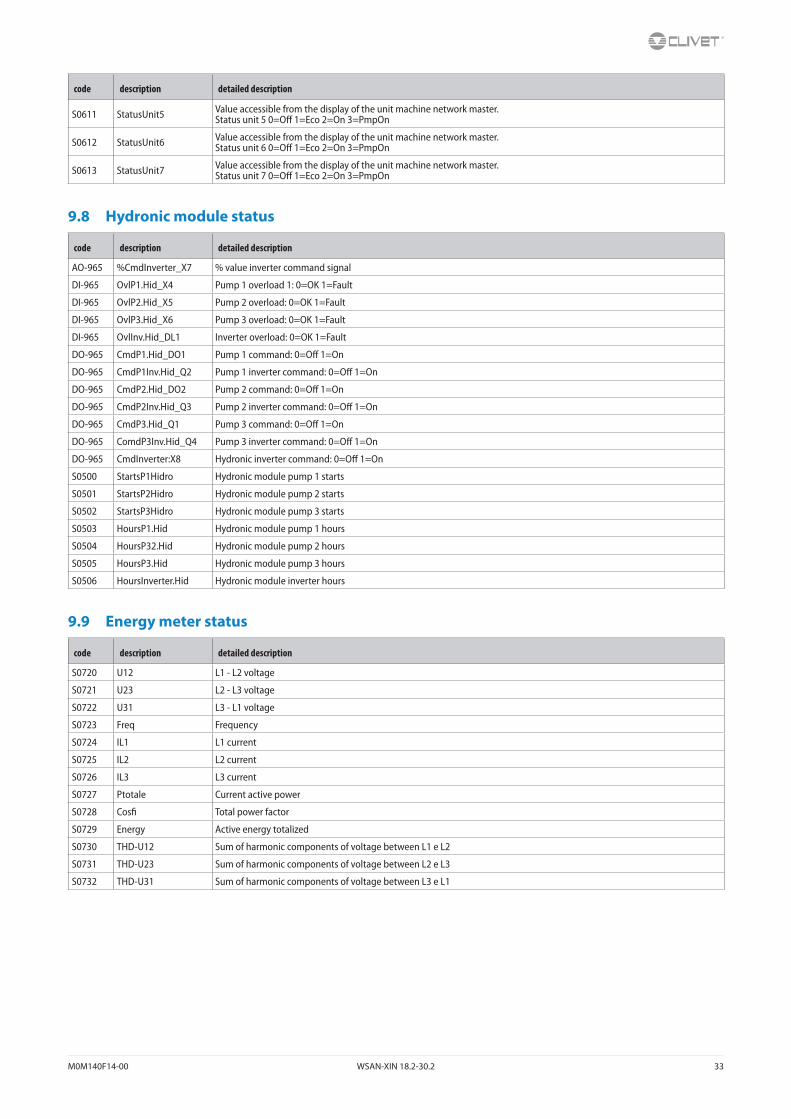
M0M140F14-00 WSAN-XIN 18.2-30.2 33
code description detailed description
S0611 StatusUnit5 Value accessible from the display of the unit machine network master.Status unit 5 0=Off 1=Eco 2=On 3=PmpOn
S0612 StatusUnit6 Value accessible from the display of the unit machine network master.Status unit 6 0=Off 1=Eco 2=On 3=PmpOn
S0613 StatusUnit7 Value accessible from the display of the unit machine network master.Status unit 7 0=Off 1=Eco 2=On 3=PmpOn
9.8 Hydronic module status
code description detailed description
AO-965 %CmdInverter_X7 % value inverter command signal
DI-965 OvlP1.Hid_X4 Pump 1 overload 1: 0=OK 1=Fault
DI-965 OvlP2.Hid_X5 Pump 2 overload: 0=OK 1=Fault
DI-965 OvlP3.Hid_X6 Pump 3 overload: 0=OK 1=Fault
DI-965 OvlInv.Hid_DL1 Inverter overload: 0=OK 1=Fault
DO-965 CmdP1.Hid_DO1 Pump 1 command: 0=Off 1=On
DO-965 CmdP1Inv.Hid_Q2 Pump 1 inverter command: 0=Off 1=On
DO-965 CmdP2.Hid_DO2 Pump 2 command: 0=Off 1=On
DO-965 CmdP2Inv.Hid_Q3 Pump 2 inverter command: 0=Off 1=On
DO-965 CmdP3.Hid_Q1 Pump 3 command: 0=Off 1=On
DO-965 ComdP3Inv.Hid_Q4 Pump 3 inverter command: 0=Off 1=On
DO-965 CmdInverter:X8 Hydronic inverter command: 0=Off 1=On
S0500 StartsP1Hidro Hydronic module pump 1 starts
S0501 StartsP2Hidro Hydronic module pump 2 starts
S0502 StartsP3Hidro Hydronic module pump 3 starts
S0503 HoursP1.Hid Hydronic module pump 1 hours
S0504 HoursP32.Hid Hydronic module pump 2 hours
S0505 HoursP3.Hid Hydronic module pump 3 hours
S0506 HoursInverter.Hid Hydronic module inverter hours
9.9 Energy meter status
code description detailed description
S0720 U12 L1 - L2 voltage
S0721 U23 L2 - L3 voltage
S0722 U31 L3 - L1 voltage
S0723 Freq Frequency
S0724 IL1 L1 current
S0725 IL2 L2 current
S0726 IL3 L3 current
S0727 Ptotale Current active power
S0728 Cosfi Total power factor
S0729 Energy Active energy totalized
S0730 THD-U12 Sum of harmonic components of voltage between L1 e L2
S0731 THD-U23 Sum of harmonic components of voltage between L2 e L3
S0732 THD-U31 Sum of harmonic components of voltage between L3 e L1

34 WSAN-XIN 18.2-30.2 M0M140F14-00
10 AccessoriesREFRIGERANT CIRCUIT
CCCA Copper / aluminium condenser coil with acrylic lining
CCCA1 Copper / aluminium condenser coil with Energy Guard DCC Aluminum
Air side features
HEDIF Diffuser for high efficiency axial fan
WATER CIRCUIT
HYG1 Hydronic assembly unit with 1 ON/OFF pump
HYG2 Hydronic assembly with 2 ON/OFF pumps
VARYP VARYFLOW + (2 inverter pumps)
VACS DHW switching valve: required
IFWX Steel mesh strainer on the water side
SYSTEM ADMINISTRATORS
CMMBX serial communication module to supervisor (Modbus)
CMSLWX LonWorks serial communication module
CMSC10 Serial communication module to LonWorks supervisor
CMSC9 Serial communication module to Modbus supervisor
CMSC8 Serial communication module to BACnet supervisor
BACX BACnet serial communication module
ELECTRIC CIRCUIT
RCTX Remote control
PM phase monitor
MF2 Multi-function phase monitor
SFSTR4N disposal for inrush current reduction, for unit 400/3/50+N
PFCP power factor correction capacitors (cosfi > 0.9)
INSTALLATION
AVIBX Anti-vibration mount support
PGFC finned coil protection grill
PGFCX finned coil protection grill
X - When the letter X is placed at the end, this means that the accessory is supplied separately. If there is no X in the code, the accessory is mounted in the fac-tory.
M0M140F14-00 WSAN-XIN 18.2-30.2 35
10.1 Configurations
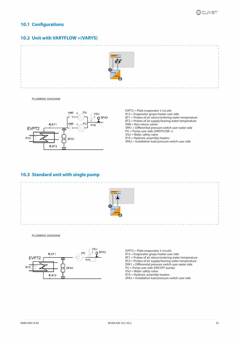
10.2 Unit with VARYFLOW +(VARYS)
PLUMBING DIAGRAM
10.3 Standard unit with single pump
PLUMBING DIAGRAM
EVPT2 = Plate evaporator 2 circuitsR13 = Evaporator gropu heater user sideBT1 = Probes of air return/entering water temperatureBT2 = Probes of air supply/leaving water temperatureVNR = Non return valvesSPA1 = Differential pressure switch user water sidePU = Pump user side (VARYFLOW +)VSU = Water safety valveR19 = Hydronic assembly heatersSPA2 = Installation load pressure switch user side
EVPT2 = Plate evaporator 2 circuitsR13 = Evaporator gropu heater user sideBT1 = Probes of air return/entering water temperatureBT2 = Probes of air supply/leaving water temperatureSPA1 = Differential pressure switch user water sidePU = Pump user side (ON/OFF pump)VSU = Water safety valveR19 = Hydronic assembly heatersSPA2 = Installation load pressure switch user side
36 WSAN-XIN 18.2-30.2 M0M140F14-00
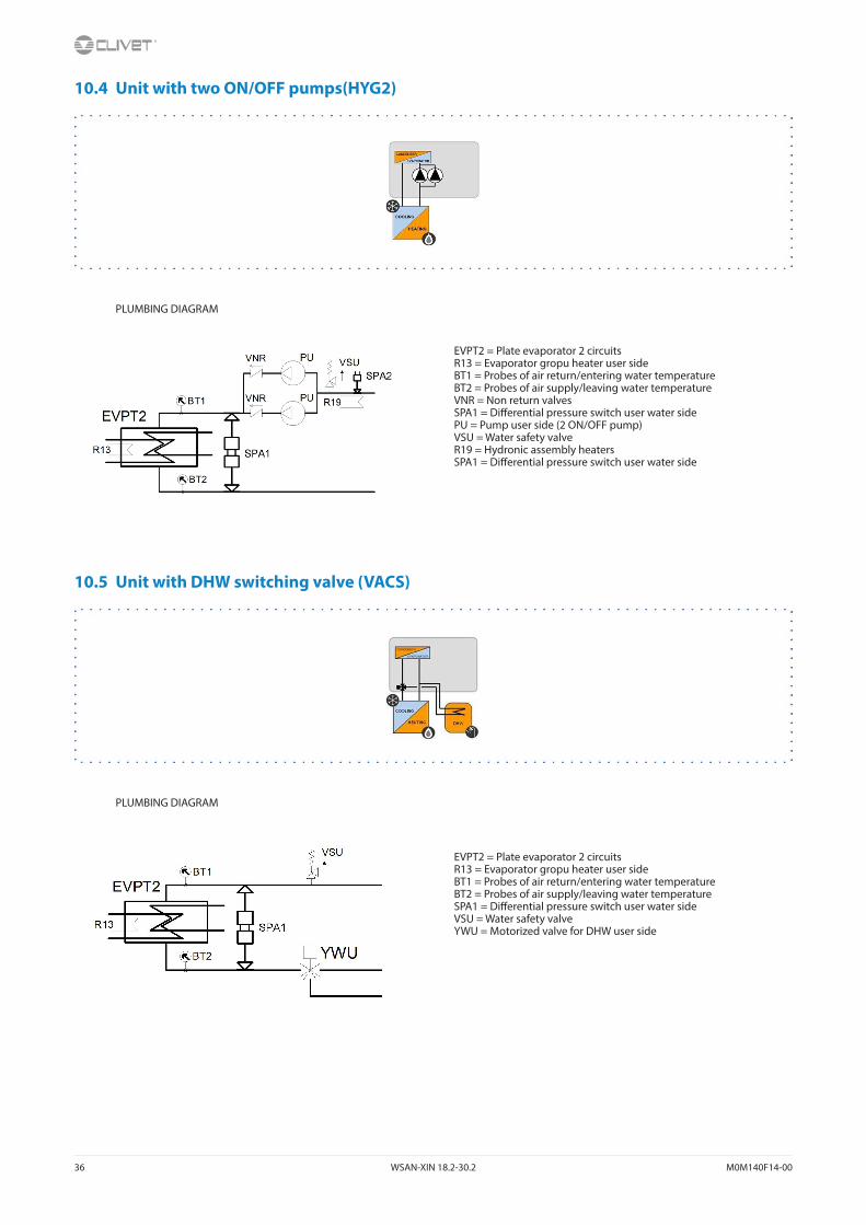
10.4 Unit with two ON/OFF pumps(HYG2)
PLUMBING DIAGRAM
10.5 Unit with DHW switching valve (VACS)
PLUMBING DIAGRAM
EVPT2 = Plate evaporator 2 circuitsR13 = Evaporator gropu heater user sideBT1 = Probes of air return/entering water temperatureBT2 = Probes of air supply/leaving water temperatureVNR = Non return valvesSPA1 = Differential pressure switch user water sidePU = Pump user side (2 ON/OFF pump)VSU = Water safety valveR19 = Hydronic assembly heatersSPA1 = Differential pressure switch user water side
EVPT2 = Plate evaporator 2 circuitsR13 = Evaporator gropu heater user sideBT1 = Probes of air return/entering water temperatureBT2 = Probes of air supply/leaving water temperatureSPA1 = Differential pressure switch user water sideVSU = Water safety valveYWU = Motorized valve for DHW user side
M0M140F14-00 WSAN-XIN 18.2-30.2 37
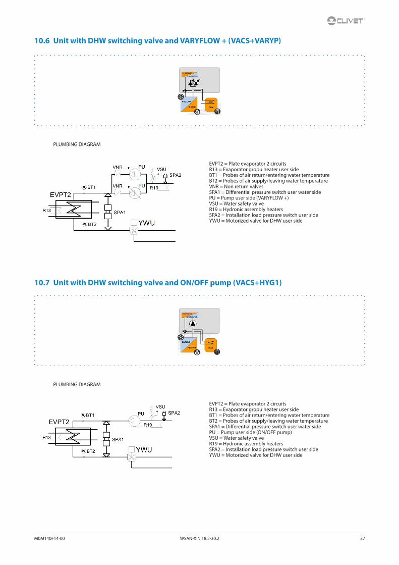
10.6 Unit with DHW switching valve and VARYFLOW + (VACS+VARYP)
PLUMBING DIAGRAM
10.7 Unit with DHW switching valve and ON/OFF pump (VACS+HYG1)
PLUMBING DIAGRAM
EVPT2 = Plate evaporator 2 circuitsR13 = Evaporator gropu heater user sideBT1 = Probes of air return/entering water temperatureBT2 = Probes of air supply/leaving water temperatureVNR = Non return valvesSPA1 = Differential pressure switch user water sidePU = Pump user side (VARYFLOW +)VSU = Water safety valveR19 = Hydronic assembly heatersSPA2 = Installation load pressure switch user sideYWU = Motorized valve for DHW user side
EVPT2 = Plate evaporator 2 circuitsR13 = Evaporator gropu heater user sideBT1 = Probes of air return/entering water temperatureBT2 = Probes of air supply/leaving water temperatureSPA1 = Differential pressure switch user water sidePU = Pump user side (ON/OFF pump)VSU = Water safety valveR19 = Hydronic assembly heatersSPA2 = Installation load pressure switch user sideYWU = Motorized valve for DHW user side
38 WSAN-XIN 18.2-30.2 M0M140F14-00
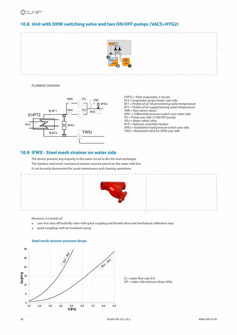
10.8 Unit with DHW switching valve and two ON/OFF pumps (VACS+HYG2)
PLUMBING DIAGRAM
10.9 IFWX - Steel mesh strainer on water sideThe device prevents any impurity in the water circuit to dirt the heat exchanger.
The stainless steel mesh mechanical strainer must be placed on the water inlet line.
It can be easily dismounted for usual maintenance and cleaning operations.
Moreover, it consists of:
• cast-iron shut-off butterfly valve with quick coupling and throttle drive and mechanical calibration stop
• quick couplings with an insulated casing
Steel mesh strainer pressure drops
EVPT2 = Plate evaporator 2 circuitsR13 = Evaporator gropu heater user sideBT1 = Probes of air return/entering water temperatureBT2 = Probes of air supply/leaving water temperatureVNR = Non return valvesSPA1 = Differential pressure switch user water sidePU = Pump user side (2 ON/OFF pump)VSU = Water safety valveR19 = Hydronic assembly heatersSPA2 = Installation load pressure switch user sideYWU = Motorized valve for DHW user side
Q = water flow rate (l/s)DP = water side pressure drops (kPa)
M0M140F14-00 WSAN-XIN 18.2-30.2 39
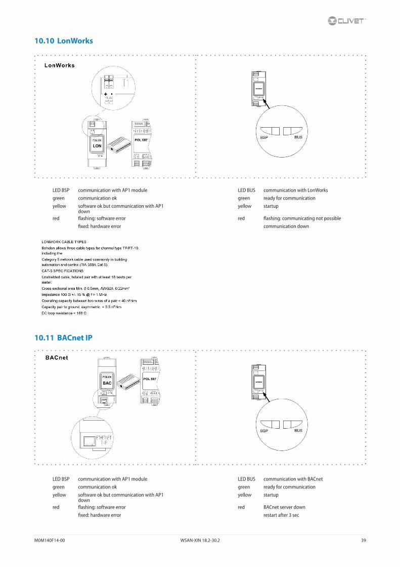
10.10 LonWorks
LED BSP communication with AP1 module LED BUS communication with LonWorksgreen communication ok green ready for communicationyellow software ok but communication with AP1
downyellow startup
red flashing: software error red flashing: communicating not possiblefixed: hardware error communication down
10.11 BACnet IP
LED BSP communication with AP1 module LED BUS communication with BACnetgreen communication ok green ready for communicationyellow software ok but communication with AP1
downyellow startup
red flashing: software error red BACnet server downfixed: hardware error restart after 3 sec

40 WSAN-XIN 18.2-30.2 M0M140F14-00
10.12 Modbus - RS485
LED BSP communication with AP1 module LED BUS communication with Modbusgreen communication ok green communication okyellow software ok but communication with AP1
downyellow startup / channel not communicating
red flashing: software error red communication downfixed: hardware error
Path
Main menu Unit Parameters Modbus
Parameters Short description Description
P0445: T1 bus termination Termination resistor activation on T1 POL902 [0] port = Passive [1] = Active
P0446: T2 bus termination Termination resistor activation on T2 POL902 [0] port = Passive [1] = Active
A. Unit
B. Metal conduit
C. Metal septums
D. Metal-lined sheath (sleeve)
Modbus / LonWorks / BACnet Cable requirementsCouple of conductors twisted and shielded
Section of conductor 0,22mm2…0,35mm2
Nominal capacity between conductors < 50 pF/m
Nominal impedance 120 Ω
Recommended cable BELDEN 3106A
• Every RS485 serial line must be set up using the ‘In/Out’ bus system.
• Other types of networks are not allowed, such as Star or Ring networks.
• The difference in potential between the earth of the two RS485 devices that the cable shielding needs to be connected to must be lower than 7 V
• There must be suitable arresters to protect the serial lines from the effects of atmospheric discharges
• A 120 ohm resistance must be located on the end of the serial line. Alternatively, when the last serial board is equipped with an internal terminator, it must be enabled using the specific jumper, dip switch or link.
• The cable must have insulation features and non-flame propagation in accordance with applicable regulations.
• The RS485 serial line must be kept as far away as possible from sources of electromagnetic interference.
M0M140F14-00 WSAN-XIN 18.2-30.2 41
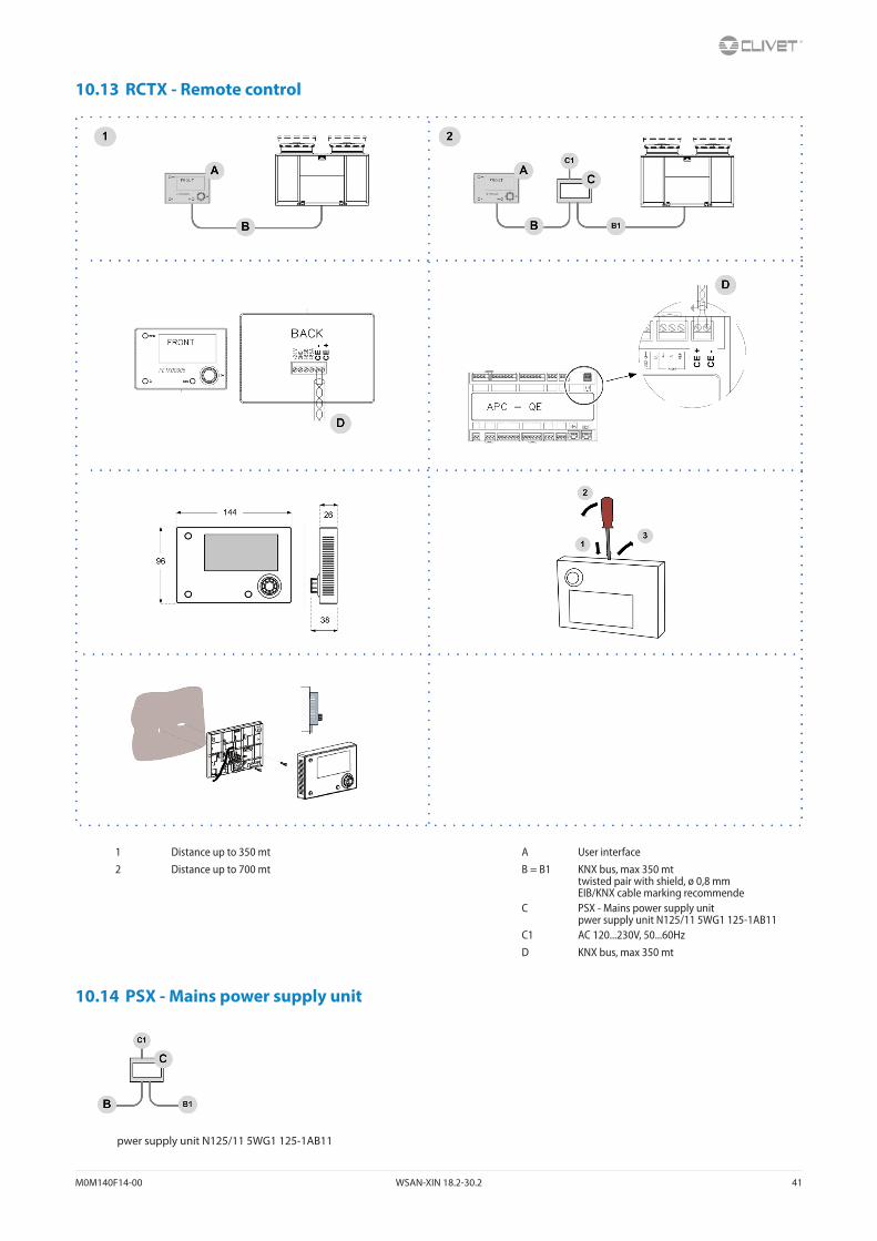
10.13 RCTX - Remote control
1 Distance up to 350 mt A User interface2 Distance up to 700 mt B = B1 KNX bus, max 350 mt
twisted pair with shield, ø 0,8 mmEIB/KNX cable marking recommende
C PSX - Mains power supply unitpwer supply unit N125/11 5WG1 125-1AB11
C1 AC 120...230V, 50...60HzD KNX bus, max 350 mt
10.14 PSX - Mains power supply unit
pwer supply unit N125/11 5WG1 125-1AB11
42 WSAN-XIN 18.2-30.2 M0M140F14-00
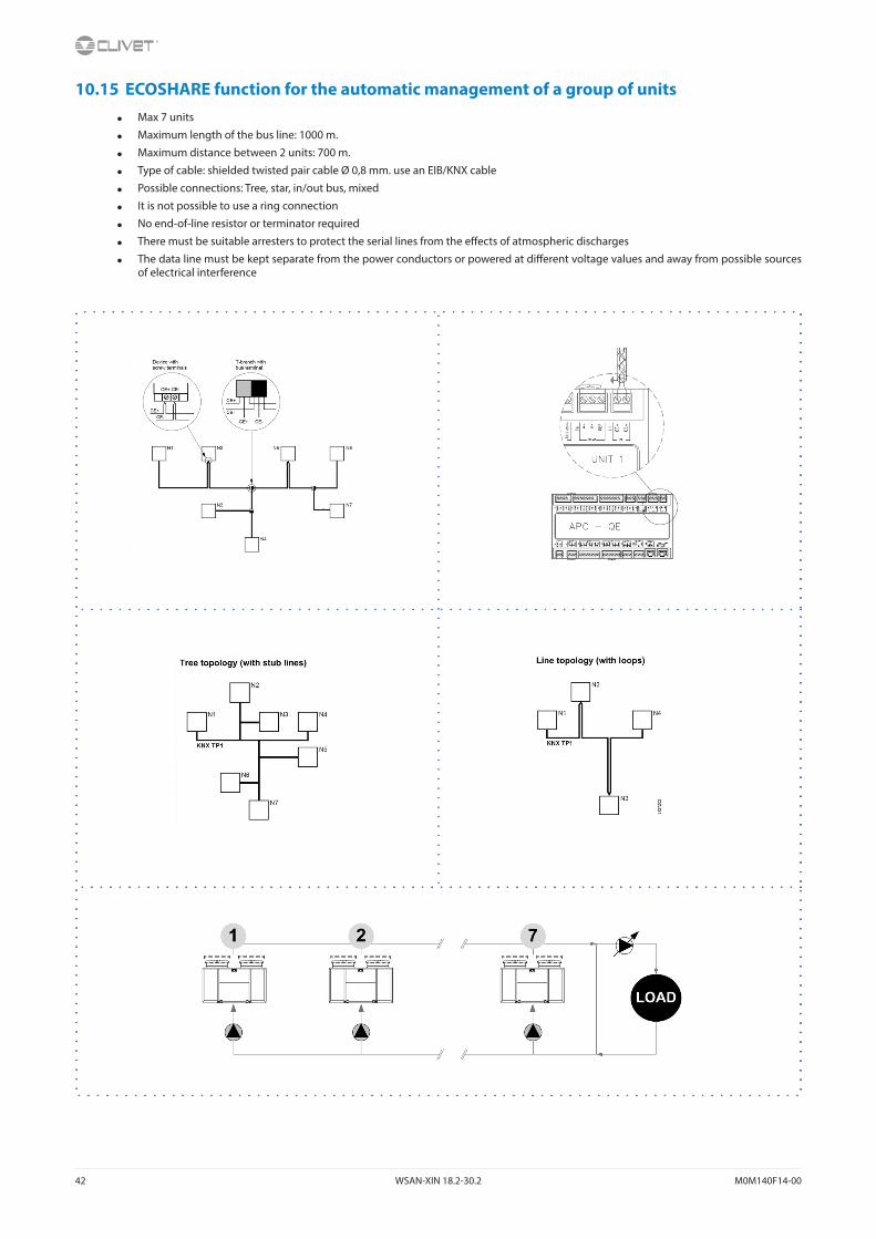
10.15 ECOSHARE function for the automatic management of a group of units
• Max 7 units
• Maximum length of the bus line: 1000 m.
• Maximum distance between 2 units: 700 m.
• Type of cable: shielded twisted pair cable Ø 0,8 mm. use an EIB/KNX cable
• Possible connections: Tree, star, in/out bus, mixed
• It is not possible to use a ring connection
• No end-of-line resistor or terminator required
• There must be suitable arresters to protect the serial lines from the effects of atmospheric discharges
• The data line must be kept separate from the power conductors or powered at different voltage values and away from possible sources of electrical interference

M0M140F14-00 WSAN-XIN 18.2-30.2 43
If there are more units connected in a local network set the mode of operation.
MODE AEvery unit manages its own compressors according to the setpoint.
Every unit optimizes its refrigeration circuits.
Pumps always active, even with compressor stoped.
P0343 = 0
P0344 > 0 °C
setpoint1 > setpoint2 > setpoint3
or
setpoint1 < setpoint2 < setpoint3
MODE BThe master manages the single cooling.
The master optimizes individual refrigerant circuits.
Pumps always active, even with compressor stoped.
P0343 = 1
P0344 = 0 °C
setpoint1 = setpoint2 = setpoint3
plus: optimal H2O temperature control
MODE CThe master manages the single cooling.
The master optimizes individual refrigerant circuits.
Active pumps only with active compressors.
P0343 = 2
P0344 = 0 °C
setpoint1 = setpoint2 = setpoint3
plus: minimum pumps consumption need balanced system (t1 = t2 = t3)
Path: Main Menu / Unit parameters / Master Slave
Parameters Short description Description
P0340: Address unit ProcessBus address unit
P0341: Unit network Number of network-connected units including the master
P0342: Standby unit Number of units kept in standby
P0343: TypeRegMS Operation mode: 0=mode A; 1=mode B; 2=mode C
P0344: Offset Trm MS Temperature Offset the master sum or subtract, depending on the way you set, in order of priority, to the set point of the slave

44 WSAN-XIN 18.2-30.2 M0M140F14-00
10.16 Climatic TExt
Menu accessible only after having entered the password.
Access reserved only to specifically trained personnel.
The parameter modification can cause irreversible damages.
The setpoint defined by the temperature curve is shown at status S0010: ActualSptTExt
Only if P0053: En Climatica ≠ 0
Path: Main Menu / Unit parameters / Climatica TExt
Example
Step Display Action Menu/Variable Keys Notes
1 Press 3 sec.
2 Password Set Password
3 Press
4 Main menu Select Unit parameters
5 Unit parameters Select Climatic TExt
6 Climatic TExt (pwd) Select Parameter
7 Set
8 Confirm
9 Press 3 sec.
10 Select Local connections
Path: Main Menu / Unit parameters / Climatica TExt
Parameters Short description Description
P0265: CSptLow setpoint temperature value when the air temperature value is AirAtSptLowC
P0266: AirAtSptLowC external air temperature value where the calculated setpoint takes on the value given by SptLowC
P0267: CSptHigh setpoint temperature value when the air temperature value is AirAtSptHigC
P0268: AirAtSptHigC external air temperature value where the calculated setpoint takes on the value given by SptHigC
M0M140F14-00 WSAN-XIN 18.2-30.2 45
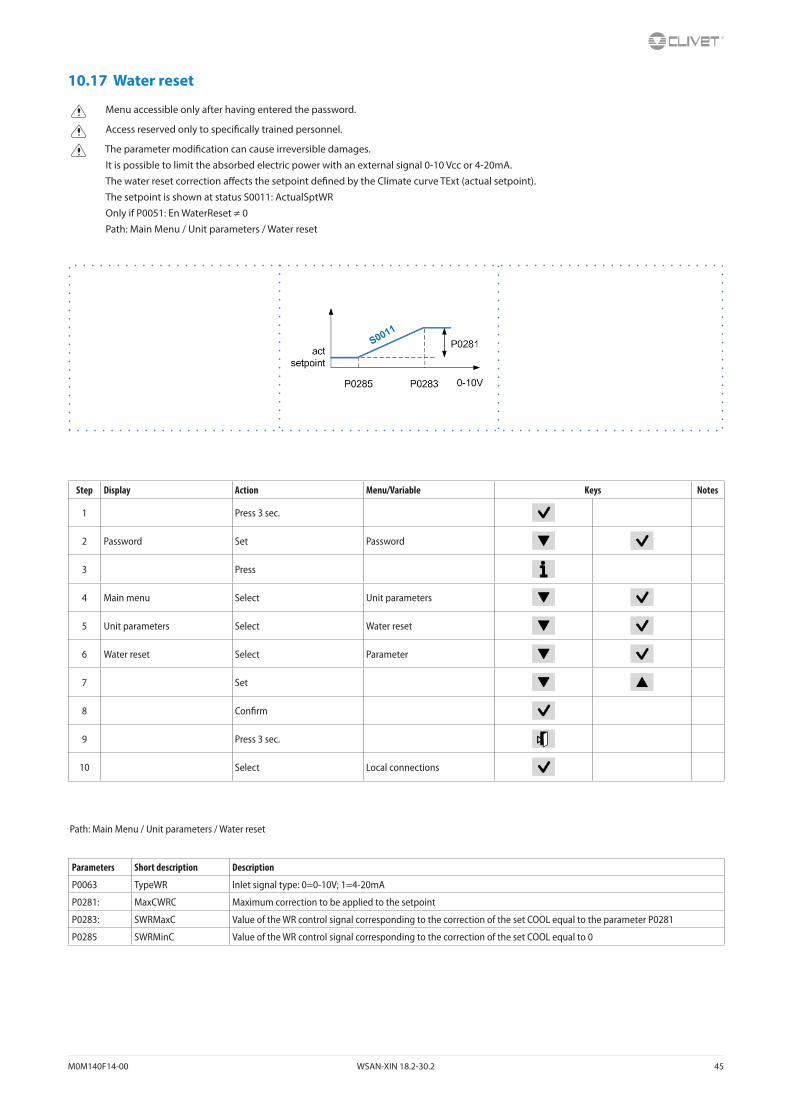
10.17 Water reset
Menu accessible only after having entered the password.
Access reserved only to specifically trained personnel.
The parameter modification can cause irreversible damages.
It is possible to limit the absorbed electric power with an external signal 0-10 Vcc or 4-20mA.
The water reset correction affects the setpoint defined by the Climate curve TExt (actual setpoint).
The setpoint is shown at status S0011: ActualSptWR
Only if P0051: En WaterReset ≠ 0
Path: Main Menu / Unit parameters / Water reset
Step Display Action Menu/Variable Keys Notes
1 Press 3 sec.
2 Password Set Password
3 Press
4 Main menu Select Unit parameters
5 Unit parameters Select Water reset
6 Water reset Select Parameter
7 Set
8 Confirm
9 Press 3 sec.
10 Select Local connections
Path: Main Menu / Unit parameters / Water reset
Parameters Short description Description
P0063 TypeWR Inlet signal type: 0=0-10V; 1=4-20mA
P0281: MaxCWRC Maximum correction to be applied to the setpoint
P0283: SWRMaxC Value of the WR control signal corresponding to the correction of the set COOL equal to the parameter P0281
P0285 SWRMinC Value of the WR control signal corresponding to the correction of the set COOL equal to 0

46 WSAN-XIN 18.2-30.2 M0M140F14-00
10.18 AVIBX - Antivibration supports
Code Size W1 W2 W3 W4
PE182701 18.2-30.2BB200 - 60 Sh BB200 - 60 Sh BB200 - 45 Sh BB200 - 45 Sh
RED RED BEIGE BEIGE
M0M140F14-00 WSAN-XIN 18.2-30.2 47
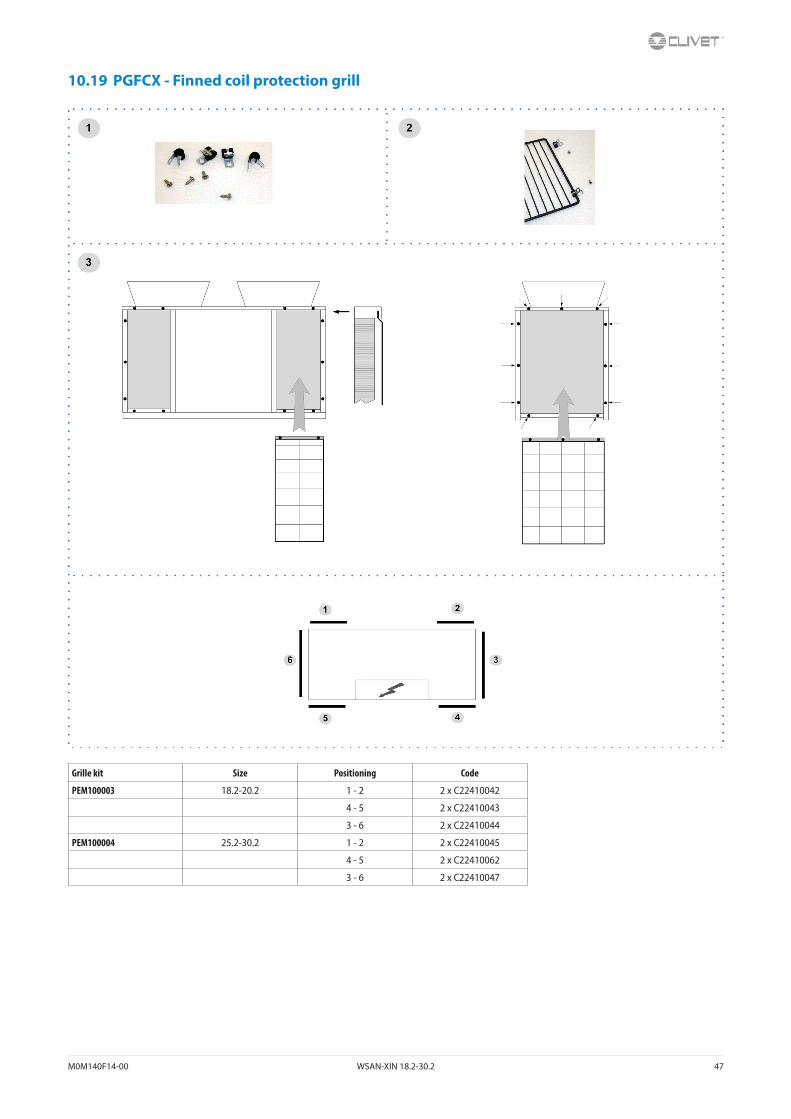
10.19 PGFCX - Finned coil protection grill
Grille kit Size Positioning Code
PEM100003 18.2-20.2 1 - 2 2 x C22410042
4 - 5 2 x C22410043
3 - 6 2 x C22410044
PEM100004 25.2-30.2 1 - 2 2 x C22410045
4 - 5 2 x C22410062
3 - 6 2 x C22410047

48 WSAN-XIN 18.2-30.2 M0M140F14-00
11 Decommissioning
11.1 DisconnectingOnly authorised personnel must disconnect the unit.
Avoid leak or spills into the environment.
Before disconnecting the unit, the following must be recovered, if present:
• refrigerant gas
• anti-freeze solutions in the water circuit
Awaiting dismantling and disposal, the unit can also be stored outdoors, if the electrical, cooling and water circuits of the unit have 100% integrity and are isolated, bad weather and rapid change in temperature will not result in any environmental impact.
11.2 Dismantling and disposalThe unit must always be sent to authorised centres for dismantling and disposal.
When dismantling the unit, the fan, the motor and the coil, if operating, may be recovered by the specialist centres for reuse.
All the materials must be recovered or disposed of in compliance with the corresponding national standards in force.
For further information on the decommissioning of the unit, contact the manufacturer.
11.3 Directive EC RAEEThe units covered by the legislation in question are marked with the symbol on the side.
With the aim of protecting the environment, all of our units are produced in compliance with Directive EC on waste electrical and electronic equipment (RAEE).
The potential effects on the environment and on human health due to the presence of hazardous substances are shown in the use and maintenance manual in the section on residual risks.
Information in addition to that indicated below, if required, can be obtained from the manufacturer/distributor/importer, who are responsible for the collection/handling of waste originating from equipment covered by EC-RAEE. This information is also available from the retailer who sold this appliance or from the local authorities who handle waste.
Directive EC-RAEE requires disposal and recycling of electrical and electronic equipment as described therein to be handled through appropriate collection, in suitable centres, separate from collection for the disposal of mixed urban waste.
The user must not dispose of the unit at the end of its life cycle as urban waste, it must instead be handed over to appropriate collection centres as set forth by current standards or as instructed by the distributor.
M0M140F14-00 WSAN-XIN 18.2-30.2 49
12 Residual risks
General descriptionIn this section the most common situations are indicated,as these cannot be controlled by the manufacturer and could be a source of risk situations for people or things.Danger zoneThis is an area in which only an authorised operator may work.The danger zone is the area inside the unit which is accessible only with the deliberate removal of protections or parts thereof.HandlingThe handling operations, if implemented without all of the protec-tion necesssary and without due caution, may cause the drop or the tipping of the unit with the consequent damage, even serious, to persons, things or the unit itself.Handle the unit following the instructions provided in the present manual regarding the packaging and in compliance with the local regulations in force.Should the refrigerant leak please refer to the refrigerant “Safety sheet”.InstallationThe incorrect installation of the unit could cause water leaks, condensate accumulation, leaking of the refrigerant, electric shock, poor operation or damage to the unit itself.Check that the installation has been implemented by qualified technical personnel only and that the instructions contained in the present manual and the local regulations in force have been adhered to.The installation of the unit in a place where even infrequent leaks of inflammable gas and the accumulation of this gas in the area sur-rounding the area occur could cause explosions or fires.Carefully check the positioning of the unit.The installation of the unit in a place unsuited to support its weight and/or guarantee adequate anchorage may result in consequent damage to things, people or the unit itself.Carefully check the positioning and the anchoring of the unit.Easy access to the unit by children, unauthorised persons or animals may be the source of accidents, some serious.Install the unit in areas which are only accessible to authorised person and/or provide protection against intrusion into the danger zone.General risksSmell of burning, smoke or other signals of serious anomalies may indicate a situation which could cause damage to people, things or the unit itself.Electrically isolate the unit (yellow-red isolator).Contact the authorised service centre to identify and resolve the problem at the source of the anomaly.Accidental contact with exchange batteries, compressors, air deliv-ery tubes or other components may cause injuries and/or burns.Always wear suitable clothing including protective gloves to work inside the danger zone.Maintenance and repair operations carried out by non-qualified personnel may cause damage to persons, things or the unit itself.Always contact the qualified assistance centre.Failing to close the unit panels or failure to check the correct tightening of all of the panelling fixing screws may cause damage to persons, things or the unit itself.Periodically check that all of the panels are correctly closed and fixed.If there is a fire the temperature of the refrigerant could reach values that increase the pressure to beyond the safety valve with the consequent possible projection of the refrigerant itself or explosion of the circuit parts that remain isolated by the closure of the tap.Do not remain in the vicinity of the safety valve and never leave the refrigerating system taps closed.
Electric partsAn incomplete attachment line to the electric network or with incor-rectly sized cables and/or unsuitable protective devices can cause electric shocks, intoxication, damage to the unit or fires.Carry out all of the work on the electric system referring to the electric layout and the present manual ensuring the use of a system thereto dedicated.An incorrect fixing of the electric components cover may lead to the entry of dust, water etc inside and may consequently electric shocks, damage to the unit or fires.Always fix the unit cover properly.When the metallic mass of the unit is under voltage and is not correctly connected to the earthing system it may be as source of electric shock and electrocution.Always pay particular attention to the implementation of the earth-ing system connections.Contact with parts under voltage accessible inside the unit after the removal of the guards can cause electric shocks, burns and electrocution.Open and padlock the general isolator prior to removing the guards and signal work in progress with the appropriate sign.Contact with parts that could be under voltage due to the start up of the unit may cause electric shocks, burns and electrocution.When voltage is necessary for the circuit open the isolator on the attachment line of the unit itself, padlock it and display the appro-priate warning sign.Moving partsContact with the transmissions or with the fan aspiration can cause injuries.Prior to entering the inside of the unit open the isolater situated on the connection line of the unit itself, padlock and display the appropriate warning sign.Contact with the fans can cause injury.Prior to removing the protective grill or the fans, open the isolator on the attachment line of the unit itself, padlock it and display the appropriate warning sign.RefrigerantThe intervention of the safety valve and the consequent expulsion of the gas refrigerant may cause injuries and intoxication.Always wear suitable clothing including protective gloves and eyeglasses for operations inside the danger zone.Should the refrigerant leak please refer to the refrigerant “Safety sheet”.Contact between open flames or heat sources with the refrigerant or the heating of the gas circuit under pressure (e.g. during welding operations) may cause explosions or fires.Do not place any heat source inside the danger zone.The maintenance or repair interventions which include welding must be carried out with the system off.Hydraulic partsDefects in tubing, the attachments or the removal parts may cause a leak or water projection with the consequent damages to people, things or shortcircuit the unit.
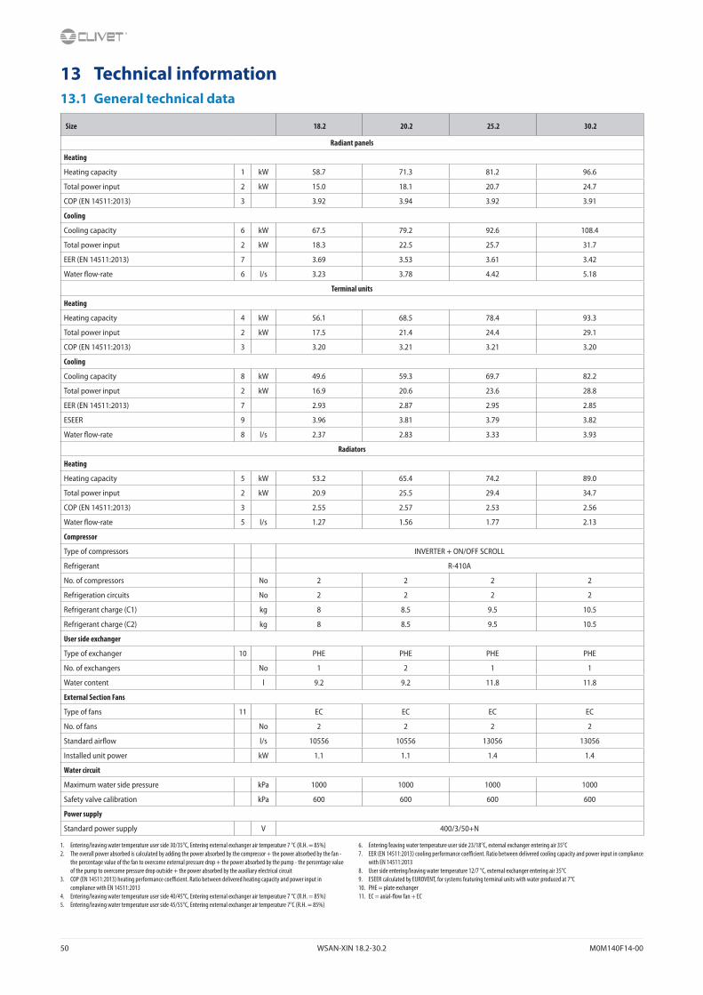
50 WSAN-XIN 18.2-30.2 M0M140F14-00
13 Technical information13.1 General technical data
Size 18.2 20.2 25.2 30.2
Radiant panels
Heating
Heating capacity 1 kW 58.7 71.3 81.2 96.6
Total power input 2 kW 15.0 18.1 20.7 24.7
COP (EN 14511:2013) 3 3.92 3.94 3.92 3.91
Cooling
Cooling capacity 6 kW 67.5 79.2 92.6 108.4
Total power input 2 kW 18.3 22.5 25.7 31.7
EER (EN 14511:2013) 7 3.69 3.53 3.61 3.42
Water flow-rate 6 l/s 3.23 3.78 4.42 5.18
Terminal units
Heating
Heating capacity 4 kW 56.1 68.5 78.4 93.3
Total power input 2 kW 17.5 21.4 24.4 29.1
COP (EN 14511:2013) 3 3.20 3.21 3.21 3.20
Cooling
Cooling capacity 8 kW 49.6 59.3 69.7 82.2
Total power input 2 kW 16.9 20.6 23.6 28.8
EER (EN 14511:2013) 7 2.93 2.87 2.95 2.85
ESEER 9 3.96 3.81 3.79 3.82
Water flow-rate 8 l/s 2.37 2.83 3.33 3.93
Radiators
Heating
Heating capacity 5 kW 53.2 65.4 74.2 89.0
Total power input 2 kW 20.9 25.5 29.4 34.7
COP (EN 14511:2013) 3 2.55 2.57 2.53 2.56
Water flow-rate 5 l/s 1.27 1.56 1.77 2.13
Compressor
Type of compressors INVERTER + ON/OFF SCROLL
Refrigerant R-410A
No. of compressors No 2 2 2 2
Refrigeration circuits No 2 2 2 2
Refrigerant charge (C1) kg 8 8.5 9.5 10.5
Refrigerant charge (C2) kg 8 8.5 9.5 10.5
User side exchanger
Type of exchanger 10 PHE PHE PHE PHE
No. of exchangers No 1 2 1 1
Water content l 9.2 9.2 11.8 11.8
External Section Fans
Type of fans 11 EC EC EC EC
No. of fans No 2 2 2 2
Standard airflow l/s 10556 10556 13056 13056
Installed unit power kW 1.1 1.1 1.4 1.4
Water circuit
Maximum water side pressure kPa 1000 1000 1000 1000
Safety valve calibration kPa 600 600 600 600
Power supply
Standard power supply V 400/3/50+N
1. Entering/leaving water temperature user side 30/35°C, Entering external exchanger air temperature 7 °C (R.H. = 85%)2. The overall power absorbed is calculated by adding the power absorbed by the compressor + the power absorbed by the fan -
the percentage value of the fan to overcome external pressure drop + the power absorbed by the pump - the percentage value of the pump to overcome pressure drop outside + the power absorbed by the auxiliary electrical circuit
3. COP (EN 14511:2013) heating performance coefficient. Ratio between delivered heating capacity and power input in compliance with EN 14511:2013
4. Entering/leaving water temperature user side 40/45°C, Entering external exchanger air temperature 7 °C (R.H. = 85%)5. Entering/leaving water temperature user side 45/55°C, Entering external exchanger air temperature 7°C (R.H. = 85%)
6. Entering/leaving water temperature user side 23/18°C, external exchanger entering air 35°C7. EER (EN 14511:2013) cooling performance coefficient. Ratio between delivered cooling capacity and power input in compliance
with EN 14511:20138. User side entering/leaving water temperature 12/7 °C, external exchanger entering air 35°C9. ESEER calculated by EUROVENT, for systems featuring terminal units with water produced at 7°C10. PHE = plate exchanger11. EC = axial-flow fan + EC

M0M140F14-00 WSAN-XIN 18.2-30.2 51
13.2 Sound levels
Size
Sound power level (dB) Sound power level
Sound pressure levelOctave band (Hz)
63 125 250 500 1000 2000 4000 8000 dB(A) dB(A)
18.2 90 83 78 80 78 72 67 61 82 65
20.2 89 82 80 81 77 72 64 59 82 65
25.2 90 83 80 81 79 74 68 60 83 66
30.2 91 84 82 83 78 75 66 59 84 66
Sound levels refer to units with full load under nominal test conditions.The sound pressure level refers to a distance of 1m from the outer surface of the unit operating in an open field.Noise levels are determined using the tensiometric method (UNI EN ISO 9614-2)Data referred to the following conditions:entering / leaving exchanger water temperature user side 12/7°Centering / leaving exchanger water temperature source side 30/35°C
13.3 Admissible water flow ratesMin. (Qmin) and max. (Qmax) water flow-rates admissibles for the correct unit operation.
Size 18.2 20.2 25.2 30.2
Minimum flow [l/s] 2.0 2.0 2.6 2.6
Maximum flow-rate [l/s] 6.0 6.0 8.6 8.6
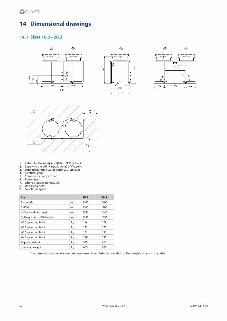
52 WSAN-XIN 18.2-30.2 M0M140F14-00
14 Dimensional drawings
14.1 Sizes 18.2 - 20.2
1. Return for the utility installation Ø 2” Victaulic2. Supply to the utility installation Ø 2” Victaulic3. DHW preparation water outlet Ø 2” Victaulic4. Electrical panel5. Compressor compartment6. Power input7. Lifting brackets (removable)8. Unit fixing holes9. Functional spaces
Size 18.2 20.2
A - Length mm 2400 2400
B - Width mm 1100 1100
C - Standard unit height mm 1540 1540
C - Height with HEDIF option mm 1690 1690
W1 Supporting Point kg 174 179
W2 Supporting Point kg 171 177
W3 Supporting Point kg 131 133
W4 Supporting Point kg 129 131
Shipping weight kg 595 610
Operating weight kg 605 620
The presence of optional accessories may result in a substantial variation of the weights shown in the table.

M0M140F14-00 WSAN-XIN 18.2-30.2 53
14.2 Sizes 25.2 - 30.2
1. Return for the utility installation Ø 2”1/2 Victaulic2. Supply to the utility installation Ø 2” 1/2 Victaulic3. DHW preparation water outlet Ø 2”1/2 Victaulic4. Electrical panel5. Compressor compartment6. Power input7. Lifting brackets (removable)8. Unit fixing holes9. Functional spaces
Size 25.2 30.2
A - Length mm 2400 2400
B - Width mm 1100 1100
C - Standard unit height mm 1790 1790
C - Height with HEDIF option mm 1940 1940
W1 Supporting Point kg 188 199
W2 Supporting Point kg 190 198
W3 Supporting Point kg 146 150
W4 Supporting Point kg 146 148
Shipping weight kg 655 675
Operating weight kg 670 695
The presence of optional accessories may result in a substantial variation of the weights shown in the table.

54 WSAN-XIN 18.2-30.2 M0M140F14-00
15 Notes

55
Page intentionally left blank

CLIVET SPAVia Camp Lonc 25, Z.I. Villapaiera - 32032 Feltre (BL) - Italy Tel. + 39 0439 3131 - Fax + 39 0439 313300 - [email protected]
CLIVET UK LTD (Sales)4 Kingdom Close, Segensworth East - Fareham, Hampshire - PO15 5TJ - United KingdomTel. + 44 (0) 1489 572238 - Fax + 44 (0) 1489 573033 - [email protected]
CLIVET AIRCON LTD (Service and Maintenance Division)Units F5&F6 Railway Triangle Ind Est, Walton Road - Portsmouth, Hampshire - PO6 1TG - United KingdomTel. +44 (0) 2392 381235 - Fax. +44 (0) 2392 381243 - [email protected]
CLIVET ESPAÑA COMERCIAL S.L. (Sales)Calle Gurb, 17 1º 1ª - 08500 Vic, Barcelona - EspañaTel: +34 93 8606248 - Fax +34 93 8855392 - [email protected]
CLIVET ESPAÑA S.A.U. (Service and Maintenance Division)Calle Real de Burgos Nº 12 - 28860 Paracuellos del Jarama, Madrid - EspañaTel. +34 91 6658280 - Fax +34 91 6657806 - [email protected]
CLIVET GmbHHummelsbütteler Steindamm 84, 22851 Norderstedt - GermanyTel. + 49 (0) 40 32 59 57-0 - Fax + 49 (0) 40 32 59 57-194 - [email protected]
CLIVET NEDERLAND B.V.Siliciumweg 20a, 3812 SX Amersfoort - NetherlandsTel. + 31 (0) 33 7503420 - Fax + 31 (0) 33 7503424 - [email protected]
CLIVET RUSSIA Elektrozavodskaya st. 24, office 509 - 107023, Moscow, RussiaTel. + 74956462009 - Fax + 74956462009 - [email protected]
CLIVET MIDEAST FZCODubai Silicon Oasis (DSO), High Bay Complex, Ind Unit No. 3, PO BOX 28178, Dubai, UAE Tel. + 9714 3208499 - Fax + 9714 3208216 - [email protected]
CLIVET AIRCONDITIONING SYSTEMS PRIVATE LIMITED4BA, Gundecha Onclave - Kherani Road,Saki Naka, Andheri (East) - Mumbai 400 072 - IndiaTel. +91 22 6193 7000 - Fax +91 22 6193 7001 - [email protected]
w w w . c l i v e t . c o m