aim-120.pdf
TRANSCRIPT

Operating Instructions
AIM - 120
CALIFORNIA BEARING RATIOTEST APPARATUS
(Motorised)
Version
1.0
Corporate Headquarters :
“Naimex House”A-8, Mohan Co-operative Industrial Estate,Mathura Road, New Delhi - 110 044, IndiaTel: +91-11-2695 0001-04, 30810200 Fax : +91-11-2695 0011, 2644 0866e-mail : [email protected] website : www.aimil.com
Regional Offices :
BENGALURU :Naimex House, 88/1, Outer Ring Road, Nagavara, Bengaluru-560 045Tel.: 91-080-2543 5001, 2543 5002, 2543 5005 to 2543 5014 Fax : 91-080-2543 5003, 2543 5004email : [email protected]
CHENNAI :
“ NOSTALGIA” Ist Floor, New No.4,Old No.14, Soundarapandiyan Street, Ashok Nagar,Chennai-600 083,Tel: 044 - 23718111 to 14 Fax: 91-44-23711629E-mail: [email protected]
HYDERABAD :315 & 316,3rd Floor, Swapnalok Complex, S.D. Road, Secunderabad –500 003 (A.P.)Tel: 91-40-30280500 to 30280519Fax: 91-40-30280520
E-mail: [email protected]
INDORE :2, Saket Nagar, Indore - 452001Tel. : 91-731-2565 944, 2565111 Fax : 91-731-2565 944
KOLKATA :B-3/2, Gillander House, Netaji Subhas Road, Kolkata - 700 001Tel.: 033-30280410, Fax : 033-22206603E-mail : [email protected]
KOCHI :Saran, 22/330 A, University Road, Cochin University (P.O.), Trikkakara, Kochi - 682 022 KeralaTel.: 0484-2577292 e-mail : [email protected], [email protected]
LUCKNOW :B-101, Arif Apartment, Rai Behari Lal Road, New Hyderabad, Lucknow-226007Tel: 0522-3208750, Fax: 0522-2781287E-mail: [email protected]
MUMBAI :BSEL Tech Park, B Wing 906, Sector 30A, Plot No. 39/5 & 39/5A, Opp. Vashi Railway Station,Vashi, Navi Mumbai.Tel:022-39183554/5,39183564(Direct), 27814741, 27814742Fax: 91-022-39183562, Email: [email protected]
VADODARA :901-902 Gunjan Towers, OFF Alembic - Gorwa Road, Subhanpura,Vadodara – 390 023Ph. No.: +91 265 3058800 (Board No.),Fax No.: +91 265 3058810, E-mail: [email protected]

1
California Bearing Ratio Test Apparatus
The equipment comprises of the following : 1 No. each
1. Load Frame, Motorised 50kN Capacity
2. Mould 150mm dia x 175mm high
3. Perforated Base Plate for mould
4. Extension Collar, 150mm dia x 50mm high
5. Penetration piston face dia 50mm.
6. Adjustable Bracket for mounting penetration dial gauge
7. Displacer Block 148mm dia x 47mm long with detachable handle
8. Annular Surcharge Weight 2.5 kg. 147mm dia with 53mm central hole
9. Surcharge Weight, 2.5 kg (slotted)
10. Perforated plate, 148mm dia with adjustable stem and lock nut
11. Tripod Stand for dial gauge
12. Cutting Collar
13. Rammer 2.6 kg x 310mm controlled fall
14. Rammer 4.9 kg x 450mm controlled fall
15. Proving Ring, capacity 50 kN (5000 kgf)
16. Dial gauge 25mm, 0.01 mm least count
17. One Tommy Pin
18. Two Spanners, size 10 x 11 , 18 x 19
19. One copy of Operating Instructions with General Assembly Drawing.
Operating InstructionsCalifornia Bearing Ratio Test Apparatus
Introduction
The California Bearing Ratio (CBR) Test Apparatus meets the requirements of IS:2720(Part XVI). It is used for the laboratory determination of California Bearing Ratio andExpansion Characteristics of undisturbed soil specimens obtained from the field and alsoof remoulded specimens of the soil compacted in the laboratory by static or dynamiccompaction. All types of soils such as sand, gravel and crushed stone can be tested. Itis also used for the selection of material and control of subgrade.
AIM-120 is supplied with Load Frame Cap. 50kN(500kgf), Motorised having three constantrates of strain.
Description
AIM-120 CBR Test Apparatus
The equipment is illustrated in the General Assembly Drawing and the numbers givenagainst the components of the equipment in the description below pertain to this drawing.
This apparatus uses motorised load frame, other components are the same as describedabove. Load Frame, Motorised, single speed is portable, sturdy and versatile. Capacityof the unit is 50 kN (5000 kgf) and rate of travel of the lead screw is 1.25mm/min. It operateson 230 volts, 50 Hz, single phase, AC supply.
Load Frame
The Load Frame consists of a body fixed on to a base. Levelling screws (26) are providedfor levelling. Two support pillars (21) are fixed to the main body. A strain dial gauge bracket(15) is provided. The support pillars are threaded at the top and a Cross Head (20) can belocated and secured in position over the entire threaded length of the pillars.
A rotating hexagonal adaptor (19) is located on the cross head. A proving ring (17) is tobe fixed to the adaptor. The load application is achieved by the upward movement of thelead screw which is secured against rotation by a sliding key. A motor with a gear box iscoupled to a clutch through a pulley and belt. The clutch is operated by a lever to engageor disengage the motor drive. A forward reverse switch (23) is also provided. A handle isprovided for working the load frame in case of power failure.
2

3
Mould : It is an open ended cylinder with an inside dia of 150mm and height of175mm. It is provided with two bosses for clamping.
Base Plate : It is a circular perforated plate (11) with a recess for positioning at eitherend of the mould. It has two studs. Both, the mould (13), and thecollar (8), can be clamped.
Collar : The Collar (8) is an open cylinder and has two bosses. It is provided witha recess for positioning on the mould.
Penetration: The Penetration Piston (16) is a steel cylinder with 50mm dia. A reamedPiston holeand a locking screw are provided for a dial gauge bracket (15).
Standard thread is provided at one end for screwing into the abutment ofproving ring (17).
Bracket : Bracket (15) consists of two rods arranged perpendicular to each other.One rod with head having a bolt and nut slides through the head of thesecond rod and it can be locked in any position by a locking screw. Thebracket can be assembled with the penetration piston. A dial gauge formeasuring the penetration can be fixed to the bracket.
Displacer : The Displacer Block (7) is made of s teel and is machined on allsides.
Block This acts as a false bottom in the cylindrical mould (13) during thecompaction process to give the required height of the compactedspecimen. A handle is provided to remove the displacer disc aftercompaction.
Surcharge : Two Surcharge Weight (3) is an annular disc weighing 2.5 kg each and isused for application for surcharge loads on the soil surface during soakingand penetration. One is slotted and other is annular.
Perforated : The Perforated Brass Plate (4) has an adjustable stem (5) and a lock nut.Plate It acts as a spacer between the soil surface and a dial gauge mounted on
a tripod in the swell test.
Tripod : The Tripod (1) is made from a one piece casting to ensure properalignment and stability at all times. A clamp is provided to hold to a dialgauge. The dial gauge is easily mounted, adjusted and removed. Thetripod fits on the top rim of the mould in a three point mounting ofundisturbed samples in the field.
4
Cutting : The Cutting Collar (6) is made of seamless steel. Recess in the upperCollar section makes it possible to mount the cutting collar at either end of the
mould to facilitate taking undisturbed samples in the field.
Rammer : The Rammer (10) is used to compact the soil sample in the mould. Thisis 4.9 kg in weight with 50mm diameter ramming face falling freely througha 450mm controlled drop. The rammer assembly is enclosed in a tubularguide sleeve. The guide sleeve has an upper steel head which is securelyfixed to the sleeve to resist damage to the assembly by the accidentalupward blows of the rammer during the compaction process. The guidesleeve has holes in both the upper and lower ends to release air whichmight develop a cushioning action during the compaction process. Thisrammer is used for heavy compaction. The Rammer (9) is the same asthe one described above but its weight is 2.6 kg and is arranged for acontrolled drop of 310mm. This is used for light compaction.
Proving Ring : The Proving Ring is for measuring the applied load and has a capacity of50 kN (5000 kgf). A calibration chart showing the relation betweendeformation and load is provided.
Dial Gauge : The Dial Gauge (14) measures the penetration of the piston. (Suppliedat an extra cost).
Specimen Preparation
i. Undisturbed Specimen
Fit the steel cutting collar to the mould and push it as gently as possible in theground, digging out the soil outside as the mould is pushed in. Remove the mouldby underdigging. Trim the top and undersides so that the correct length ofspecimen is obtained. If the soil is loose in the mould fill the annular cavity withparaffin wax.
ii. Remoulded Specimen
The dry density for remoulding shall be either the field density, or the value ofmaximum dry density estimated by the compaction tests, or any other density atwhich the bearing ratio is desired. The moisture content used for compactionshould be the optimum moisture content or the field moisture as the case may be.
Take the material passing 20mm IS Sieve. Allowance for larger material shall bemade by replacing it by an equal amount of material which passes 20mm IS Sievebut is retained on 4.75mm IS Sieve.

5
a. Statically Compacted Specimen
Calculate the weight of the wet soil at the required moisture content to give thedesired density when occupying the standard specimen volume in the mould. Mixa batch of soil thoroughly with water to give the required moisture content. Placethe correct weight of the moist soil in the mould clamped to the base plate with afilter paper in between. Place a filter paper over the soil. Position the displacerdisc on top of the filter paper with its threaded face up. Keep the assembly in acompression machine. Press the displacer disc, until it is flush with the rim of themould when the required volume of specimen is obtained although with some soiltypes it may be necessary to continue loading until the displacer disc is just belowthe rim in order to allow for the elastic recovery of the soil, when the load isremoved.
b. Dynamically Compacted Specimen
Take a representative sample of the soil weighing approximately 4.5 kg. or morefor fine grained soils and 5.5 kg or more for granular soils and mix thoroughly withwater. If the soil is to be compacted to the maximum dry density at the optimummoisture content determined in accordance with the Indian Standard Specificationusing light compaction or heavy compaction, take the exact weight of soil requiredand mix it thoroughly with the necessary quantity of water to give the determinedoptimum moisture content.
Place the displacer block on the base plate with its threaded face facing the baseplate. Keep a coarse filter paper over it. Clamp the mould with the extension collarattached to the base plate.
For light compaction method compact the wet soil into the mould in three layerseach layer being given 25 blows using the rammer weighing 2.6 kg dropping froma height of 310mm and for heavy compaction method compact the wet soil in fivelayers each layer being given 25 blows using the rammer weighing 4.9 kg droppingfrom a height of 450mm. Uniformly distribute the blows over the surface of eachlayer. Care shall be taken to keep the sleeve free from the soil to ensure a freefall of the rammer and the lump of the soil sticking to the rammer at any stage shallbe removed. Scarify each layer of the compacted soil for the succeeding layer.The amount of the soil used shall be just sufficient to fill the mould leaving about5mm to be struck off when the collar is removed. (It is necessary to control thetotal volume if soil is compacted, since it has been found that if soil struck off, afterremoving the extension is too great, the test results will be inaccurate).

Remove the extension collar and carefully trim the compacted soil and the top ofthe mould by means of a straight edge. Patch up any hole that may then developon the surface of the compacted soil by the removal of coarse material usingsmaller size material.Dismantle the mould from the base plate and record the weight of the mould andthe compacted specimen.
Remove the displacer disc from the plate and place a filter paper over it. Invertthe mould and clamp it to the base plate.
Test Procedure
i. Swell Test
Place a filter over the specimen if it not already there and position the perforatedplate with adjustable stem on the specimen. Adjust the stem height such that ittouches the plunger of the dial gauge fixed to the tripod when mounted on themould.
Apply the weight to produce a surcharge equal to the weight of the base materialand pavement in actual construction within 2.5 kg. The whole weight, however,shall not be less than 5 kg. Immerse the whole mould and weights in a tank of waterallowing free access of water to the top and bottom of the specimen.
Fix the dial gauge to the tripod and mount on the mould. Record the initial dialgauge reading. Keep this set up as such undisturbed for 96 hours. (Presumingthat the soil specimen is fully saturated) note down the dial gauge readings everyday against the time of reading.
If the the expansion ceases within 96 hours the reading may be taken upto the finalexpansion and report the total time of soaking. A shorter immersion period maybe permissible for soils that take up moisture readily, if tests show that the shorterperiod does not effect the test results. Maintain a constant water level in the tankthroughout the period. At the end of the soaking period, take the mould out of thewater tank. Remove the surcharge weight and the perforated plate.
Remove the free water and allow the specimen to drain downwards for 15 minutesbeing careful to see that the surface of the specimen is not disturbed during theremoval of the free water. Determine the weight of the mould with soaked soilsample.
6

ii. Penetration Test with AIM-120
Position the Load Frame on a firm level base. Screw in the penetrationpiston (16) to the Proving Ring.
Position the Mould on the platen fixed to the lead screw of the jack. Placethe surcharge weights, sufficient to produce an intensity of loading equalto the weight of the base material and pavement within 2.5kg but not lessthatn 5kg. If the specimen has been soaked previously, the surchargeshall be equal to that used during the soaking period. The load applicationis achieved by upward movement of the lead screw by means of an electricmotor and reduction gear combination.
The mould is moved up so that the piston is seated centrally on thespecimen and a small load less that 4kg is applied before starting to takepenetration / load observations.
Fix the dial guage to the bracket. Position the bracket in the reamed holeof the penetration piston and adjust the length of its arm such that the dialgauge plunger rests on the rim of the bracket by the locking screw on thepenetration piston.
Bring the piston in contact with the specimen and apply the smallestpossible load but in no case in excess of 4kg so that full contact isestablished between the surface of the specimen and the piston. Set theproving ring dial guage and penetration dial gauge to zero. Consider thisinitial load applied to the piston as the zero load when determining the load/ penetration relation.
Apply the load on the penetration piston so that the penetration isapproximately 1.25mm/min. Record the load readings at penetrations of0, 0.5, 1.0, 1.5, 2.0, 2.5, 3.0, 3.0, 5.0, 7.5, 10.0 and 12.5mm.
Record the the maximum load and penetration if it occurs for a penetrationof less than 12.5mm. At the end of the test dismantle the assembly anddetermine the moisture content taking about 20-50g of soil from the top3cm layer of the specimen. If the average moisture content of the wholespecimen is desired, take the moisture content samples from the entiredepth of the specimen.
7

Calculations
Expansion Ratio= x100h
dd sf −
Where
df = final dial gauge reading in mm.
ds = initial dial gauge reading in mm.
h = initial height of the specimen in mm.
Plot the load / penetration curve. A correction is applied by drawing a tangent to the curveat the point of greatest slope. The corrected curve is this tangent plus the convex portionof the original curve with the origin to the point where the tangent cuts the horizontal axis.
Corresponding to the penetration value at which the California bearing ratio is desired takethe corrected load values from the load/penetration curve and calculate the CBR.
California Bearing Ratio =
x100PP
s
t
Where
Pt = Corrected unit (or total) test load corresponding to the chosenpenetration from the load / penetration curve
Ps = Unit (or total) standard load for the same depth of penetrationas for Pt taken from the following table.
8
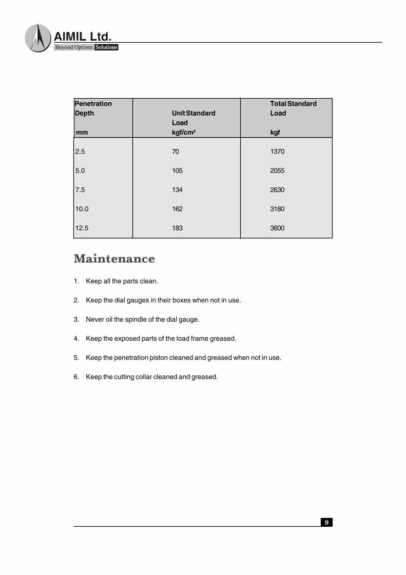
Penetration Total Standard Depth Unit Standard Load
Load mm kgf/cm² kgf
2.5 70 1370
5.0 105 2055
7.5 134 2630
10.0 162 3180
12.5 183 3600
Maintenance
1. Keep all the parts clean.
2. Keep the dial gauges in their boxes when not in use.
3. Never oil the spindle of the dial gauge.
4. Keep the exposed parts of the load frame greased.
5. Keep the penetration piston cleaned and greased when not in use.
6. Keep the cutting collar cleaned and greased.
9

10
11

12