aii33486 civic si fog light - discount honda accessories · © 2006 american honda motor co., inc....
TRANSCRIPT

© 2006 American Honda Motor Co., Inc. - All Rights Reserved. AII 33486 (0608) 1 of 14
INSTALLATIONINSTRUCTIONS
Accessory Application Publications No.
Issue Date
FOG LIGHTP/N 08V31-SVA-100A
2007 CIVIC SI
AUG 2006
All 33486
PARTS LIST
5 Wire tiesRight fog light
Left fog light
Right bracket
Left bracket
Switch harness
Fog light harness
Sub harness
Switch
Clip
4 Stepped screws
2 Washer screws
6 Self-tapping screws
Fuse (20 A)
Relay
5 Wire ties with clips
Template
Ground bolt
2 of 14 AII 33486 (0608) © 2006 American Honda Motor Co., Inc. - All Rights Reserved.
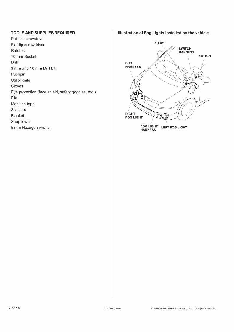
TOOLS AND SUPPLIES REQUIREDPhillips screwdriverFlat-tip screwdriverRatchet10 mm SocketDrill3 mm and 10 mm Drill bitPushpinUtility knifeGlovesEye protection (face shield, safety goggles, etc.)FileMasking tapeScissorsBlanketShop towel5 mm Hexagon wrench
6613010T
FOG LIGHTHARNESS
LEFT FOG LIGHT
SUBHARNESS
RELAY
SWITCH
SWITCHHARNESS
RIGHTFOG LIGHT
Illustration of Fog Lights installed on the vehicle

© 2006 American Honda Motor Co., Inc. - All Rights Reserved. AII 33486 (0608) 3 of 14
5311320T
FRONTBUMPER
MASKINGTAPE5311021T
RADIATORCOVER EXPANSION
CLIP
CLIPS (2) (Draw out the
clip verticallyagainst thepanel surface.)
PANEL
4. With the help of an assistant, remove the frontbumper (six clips, two screws and four bolts). Setthe front bumper on a blanket.
INSTALLATION
Customer Information: The information in thisinstallation instruction is intended for use only byskilled technicians who have the proper tools,equipment, and training to correctly and safely addequipment to your vehicle. These proceduresshould not be attempted by “do-it-yourselfers.”
1. Make sure you have the anti-theft code for theradio, then write down the frequencies for thepreset buttons.
2. Disconnect the negative cable from the battery.
3. Remove the radiator cover (four clips).
5. Apply masking tape to the front bumper around theleft fog light area.
6613061TCLIPS (6)
SCREWS (2)
FRONTBUMPER
BOLTS(2)
BOLTS(2)

4 of 14 AII 33486 (0608) © 2006 American Honda Motor Co., Inc. - All Rights Reserved.
5311050T
SCISSORS
TEMPLATE
5311042T
Cut outthe areafrom thebumper.
UTILITYKNIFE
FRONT
FRONTBUMPER
Carefully cut in theareas shown.
5311071T
DRILL(3 mm 10 mm)
MARKFRONTBUMPER
5311061T
PUSHPIN
TEMPLATE(L side)MASKING TAPE
FRONTBUMPER
6. Using a utility knife, and working from the front ofthe bumper, carefully cut out the front bumper inthe area shown. Take care not to damage thefront bumper. Remove any burrs from the edgesof the hole.
9. Tape the template marked “L” to the inside of thefront bumper below the left fog light opening. Usinga pushpin, pierce the bumper through the mark inthe template.
7. Repeat steps 5 and 6 to cut the bumper for theright fog light.
8. Using scissors, cut out the template. The template“L” is the mirror image of the template “R.”
10. While wearing eye protection, drill a 10 mm holethrough the bumper at the marked location. Firstdrill with a 3 mm drill bit and finish with a 10 mmdrill bit.
11. Repeat steps 9 and 10 to mark and drill the rightside of the front bumper.
© 2006 American Honda Motor Co., Inc. - All Rights Reserved. AII 33486 (0608) 5 of 14
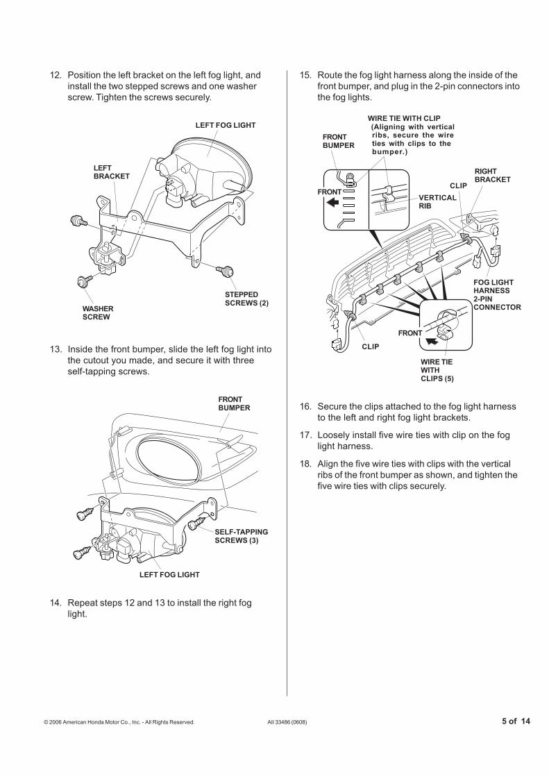
12. Position the left bracket on the left fog light, andinstall the two stepped screws and one washerscrew. Tighten the screws securely.
15. Route the fog light harness along the inside of thefront bumper, and plug in the 2-pin connectors intothe fog lights.
13. Inside the front bumper, slide the left fog light intothe cutout you made, and secure it with threeself-tapping screws.
14. Repeat steps 12 and 13 to install the right foglight.
16. Secure the clips attached to the fog light harnessto the left and right fog light brackets.
17. Loosely install five wire ties with clip on the foglight harness.
18. Align the five wire ties with clips with the verticalribs of the front bumper as shown, and tighten thefive wire ties with clips securely.
5311102T
RIGHTBRACKET
FOG LIGHTHARNESS2-PINCONNECTOR
CLIP
CLIP
FRONT
FRONTBUMPER
WIRE TIEWITHCLIPS (5)
WIRE TIE WITH CLIP (Aligning with vertical
ribs, secure the wireties with clips to thebumper.)
VERTICALRIB
FRONT
WASHERSCREW
STEPPEDSCREWS (2)
5311080T
LEFT FOG LIGHT
LEFTBRACKET
5311091T
SELF-TAPPINGSCREWS (3)
FRONTBUMPER
LEFT FOG LIGHT
6 of 14 AII 33486 (0608) © 2006 American Honda Motor Co., Inc. - All Rights Reserved.
5311110T
CLIPFOG LIGHT HARNESS2-PIN CONNECTOR
RIGHTBRACKET
5307112T
WASHERRESERVOIRTANK
BOLT(Loosen)
BOLT(Loosen.)
BOLT
5307121T
VEHICLEHARNESS
1-PINCONNECTOR
BLUE TAPE(Remove.)
SUB HARNESS
SUBHARNESS
GROUNDTERMINAL
5311301T
WASHERRESERVOIRTANK
VEHICLEFRAME
VEHICLEPANEL GROUND
BOLT
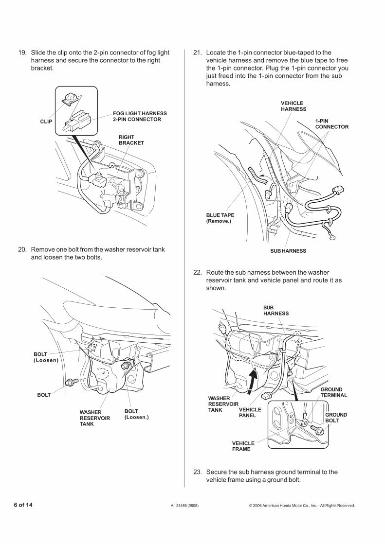
19. Slide the clip onto the 2-pin connector of fog lightharness and secure the connector to the rightbracket.
21. Locate the 1-pin connector blue-taped to thevehicle harness and remove the blue tape to freethe 1-pin connector. Plug the 1-pin connector youjust freed into the 1-pin connector from the subharness.
20. Remove one bolt from the washer reservoir tankand loosen the two bolts.
22. Route the sub harness between the washerreservoir tank and vehicle panel and route it asshown.
23. Secure the sub harness ground terminal to thevehicle frame using a ground bolt.

© 2006 American Honda Motor Co., Inc. - All Rights Reserved. AII 33486 (0608) 7 of 14
5202191T
KEY
OPENERLOCKCYLINDER
SELF-TAPPINGSCREW
COVERRETAININGTABS (6)
TRUNK LID/FUEL FILLDOOR OPENER
LEFT FRONTDOOR SILL TRIM
FRONT
5311351T
CLIPS (6)
RETAININGTAB
HOOK
5311140T
FRONTBUMPER
FOG LIGHTHARNESS2-PINCONNECTOR
SUB HARNESS2-PIN CONNECTOR
5311131T
WIRETIE
CLIP
SUB HARNESS
VEHICLEFRAME
24. Secure the two clips from the sub harness to thevehicle frame. Secure the sub harness to thevehicle harness using two wire ties.
28. Remove the cover from the trunk lid/fuel fill dooropener (six retaining tabs), and remove one self-tapping screw.
27. Reinstall the front bumper.
29. Using the ignition key, unlock the opener.
30. Raise the front side of the left front door silltrim (six clips, retaining tab and hook).
25. Reinstall the washer reservoir tank.
26. Plug the 2-pin connector from the sub harness intothe 2-pin connector of the fog light harness.

8 of 14 AII 33486 (0608) © 2006 American Honda Motor Co., Inc. - All Rights Reserved.
5202220T
WEATHERSTRIP CLIPS (2)
LEFTKICKPANEL
5311370T
STUD BOLT
UPPERCLIP
FOOTRESTLOWERCLIP
HEXAGONWRENCH
5202112T
CLIPS (2)
DRIVER’SDASHBOARDUNDER COVER
KNOB
5202121T
DRIVER’SDASHBOARDLOWER COVER
CLIPS (8)
31. Remove the footrest.
• Using a hexagon wrench, remove the lowerclip from the stud bolt.
• Using a flat-tip screwdriver, remove the upperclip from the stud bolt.
33. If equipped remove the driver’s dashboard undercover (turn the lock knob 90° counterclockwise,and release the two clips and pin).
32. Pull away the weatherstrip from left kick panel andremove the left kick panel (two clips).
34. Remove the driver’s dashboard lower cover (eightclips).
© 2006 American Honda Motor Co., Inc. - All Rights Reserved. AII 33486 (0608) 9 of 14
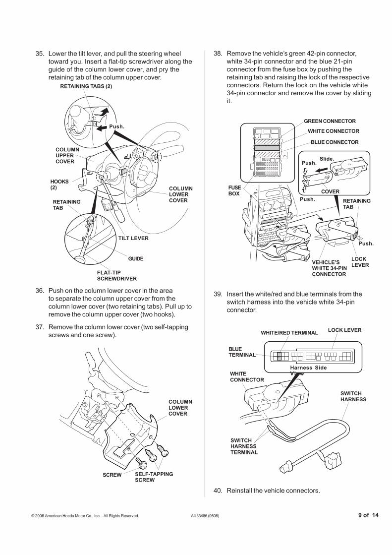
35. Lower the tilt lever, and pull the steering wheeltoward you. Insert a flat-tip screwdriver along theguide of the column lower cover, and pry theretaining tab of the column upper cover.
36. Push on the column lower cover in the area shownto separate the column upper cover from thecolumn lower cover (two retaining tabs). Pull up toremove the column upper cover (two hooks).
6608050T
COLUMNUPPERCOVER
HOOKS(2)
TILT LEVER
COLUMNLOWERCOVER
RETAINING TABS (2)
RETAININGTAB
FLAT-TIPSCREWDRIVER
GUIDE
Push.
5308530TSELF-TAPPINGSCREW
SCREW
COLUMNLOWERCOVER
37. Remove the column lower cover (two self-tappingscrews and one screw).
5307170T
WHITE/RED TERMINAL
BLUETERMINAL
Harness SideView
SWITCHHARNESSTERMINAL
SWITCHHARNESS
WHITECONNECTOR
LOCK LEVER
5307163T
FUSEBOX COVER
Push.
GREEN CONNECTOR
WHITE CONNECTOR
BLUE CONNECTOR
Slide.
VEHICLE’SWHITE 34-PINCONNECTOR
Push.
Push.
RETAININGTAB
LOCKLEVER
38. Remove the vehicle’s green 42-pin connector,white 34-pin connector and the blue 21-pinconnector from the fuse box by pushing theretaining tab and raising the lock of the respectiveconnectors. Return the lock on the vehicle white34-pin connector and remove the cover by slidingit.
39. Insert the white/red and blue terminals from theswitch harness into the vehicle white 34-pinconnector.
40. Reinstall the vehicle connectors.
10 of 14 AII 33486 (0608) © 2006 American Honda Motor Co., Inc. - All Rights Reserved.
5307202T
SWITCHHARNESS
VEHICLE 1-PINCONNECTOR
SWITCH HARNESS 1-PIN CONNECTOR
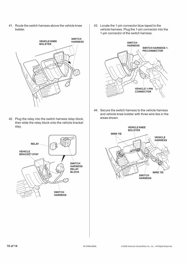
43. Locate the 1-pin connector blue-taped to thevehicle harness. Plug the 1-pin connector into the1-pin connector of the switch harness.
44. Secure the switch harness to the vehicle harnessand vehicle knee bolster with three wire ties in theareas shown.
5307212T
VEHICLEHARNESS
WIRE TIE
VEHICLE KNEEBOLSTER
WIRE TIESWITCHHARNESS
5307180T
VEHICLE KNEEBOLSTER
SWITCHHARNESS
41. Route the switch harness above the vehicle kneebolster.
42. Plug the relay into the switch harness relay block,then slide the relay block onto the vehicle bracketstay.
5307192T
RELAY
VEHICLEBRACKET STAY
SWITCHHARNESSRELAYBLOCK
SWITCHHARNESS

© 2006 American Honda Motor Co., Inc. - All Rights Reserved. AII 33486 (0608) 11 of 14
5307222T
SCREW
STEERING
SWITCH
SWITCH
VEHICLE12-PINCONNECTOR
RETAININGTAB
45. Lower the tilt lever and pull the steering wheeltoward you.
46. Turn the steering wheel 90° counterclockwise.
47. Remove the vehicle 12-pin connector from theswitch. Remove the two screws from the switch.While pushing the retaining tab, remove theswitch.
5307231T
SCREW
SWITCH
VEHICLE12-PINCONNECTOR
SWITCH
48. Install the new switch provided where the oldswitch was removed. Then plug the vehicle 12-pinconnector to the new switch. Replace the vehicleharness.Do not install the switch while holding thelever.

12 of 14 AII 33486 (0608) © 2006 American Honda Motor Co., Inc. - All Rights Reserved.
54. Reset the clock, and reset the radio stationpresets.
To raise.To lower.
AIMINGADJUSTMENTSCREW
5311251T
5307240T
Front View
FUSELOCATION“6”
20 AFUSE
FUSEBOX
49. Install the 20 A fuse into the fuse box in thelocation shown.
50. Check that all wire harnesses are routed properlyand all connectors are plugged in.
51. Reinstall all removed parts. Do not reinstall theoutboard bumper bolts at this time.
52. Reconnect the negative cable to the battery.
USE AND CARE
HOW TO OPERATE FOG LIGHTS
NOTE: The fog light lenses can cloud when the outsidetemperature is cold; this is normal and should go awayin warm weather.
• Turn the light switch to the “ ” position (headlightson low beam).
• Make the fog light switch on (indicator is on).
• If the fog light don't come on, check the fuse and allthe connectors, including the ground cable.
FOG LIGHT AIMING ADJUSTMENT
53. Adjust the fog light:
• Adjust the aim according to local laws andregulations.
• To adjust, turn the aiming adjustment knob inor out until the correct aim is obtained.
© 2006 American Honda Motor Co., Inc. - All Rights Reserved. AII 33486 (0608) 13 of 14
5311270T
FOG LIGHT
CONNECTOR
BULB
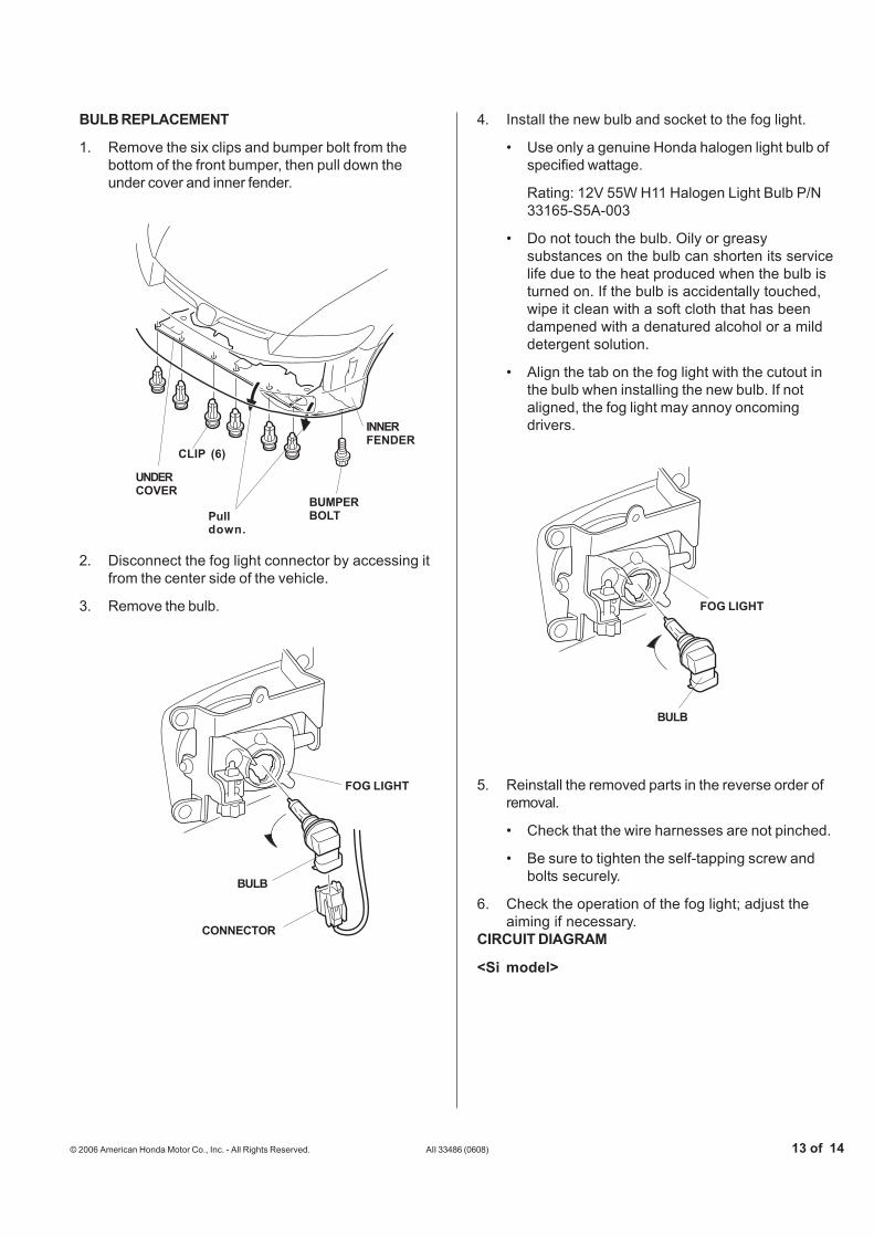
BULB REPLACEMENT
1. Remove the six clips and bumper bolt from thebottom of the front bumper, then pull down theunder cover and inner fender.
2. Disconnect the fog light connector by accessing itfrom the center side of the vehicle.
3. Remove the bulb.
6613070T
BUMPERBOLTPull
down.
INNERFENDER
UNDERCOVER
CLIP (6)
BULB
FOG LIGHT
5311280T
4. Install the new bulb and socket to the fog light.
• Use only a genuine Honda halogen light bulb ofspecified wattage.
Rating: 12V 55W H11 Halogen Light Bulb P/N33165-S5A-003
• Do not touch the bulb. Oily or greasysubstances on the bulb can shorten its servicelife due to the heat produced when the bulb isturned on. If the bulb is accidentally touched,wipe it clean with a soft cloth that has beendampened with a denatured alcohol or a milddetergent solution.
• Align the tab on the fog light with the cutout inthe bulb when installing the new bulb. If notaligned, the fog light may annoy oncomingdrivers.
5. Reinstall the removed parts in the reverse order ofremoval.
• Check that the wire harnesses are not pinched.
• Be sure to tighten the self-tapping screw andbolts securely.
6. Check the operation of the fog light; adjust theaiming if necessary.
CIRCUIT DIAGRAM
<Si model>

14 of 14 AII 33486 (0608) © 2006 American Honda Motor Co., Inc. - All Rights Reserved.
5307292T
MULTIPLEXINTEGRATEDCONTROLUNIT
UNDER-DASH FUSE/RELAY BOX
BLK
COMBINATIONLIGHT SWITCH
FOGLIGHTSWITCH0=OFF1=ON
0 1
PUR
BLUBLU
BLK
RIGHTFRONTFOG LIGHT
RELAY
WHT/RED
FOG LIGHTFUSE 20A
HEADLIGHT SWITCH
Low HiOFF
ONFOG
LIG
HT
SWIT
CH OFF - - - -
- - -
BLK BRN BROWNBLACK
YEL ORN ORANGEYELLOW
BLU PUR PURPLEBLUE
GRN GREEN
RED
PNK PINK
RED
WHT
GRY GRAY
WHITE
LT BLU
LT GRN LIGHT GREEN
LIGHT BLUE
UNDER-HOOD FUSE/RELAY BOX
BATTERY 100 A 80 A
LEFTFRONTFOG LIGHT