ahs rk100 instructions 26aug2016 - australian … operating, commissioning and maintenance...
TRANSCRIPT

Installation, operating, commissioning and maintenance instructions.
CE 0694 RK 100 - RAD - ING - MAN.INST – 1311.1 - DIGITECH C S MIAH4
Technical Specification RADIANT BRUCIATORI S.p.A. Montelabbate (PU) ITALY ENGLISH
Instruction Manual
for model
RK 100
Premix condensing system boiler


CONTENTS
1. General Information
1.1 General installation information page 1
1.2 Product conformity 3
2. Technical characteristics
2.1 Technical data 4
2.2 Dimensions 6
2.3 Internal parts of the boiler 8
2.4 Water circuit 9
2.5 System mechanical circuit 10
2.6 Circulation pump head graph 11
2.7 System accessories 12
2.8 Printed circuit board – Technical characteristics 13
2.9 Control panel 13
2.10 INFO Menu display 14
3. Installation (authorised personnel)
3.1 General warnings 15
3.2 Reference standard 15
3.3 Boiler room – installation requirements 16
3.4 Unpacking 16
3.5 Installing the boiler 17
3.6 Water connections 20
3.7 Gas connection 23
3.8 Electrical connections 24
3.9 Flue connections 29
4. Commissioning the appliance (authorised personnel)
4.1 General warnings (flushing the system) 32
4.2 Preliminary operations 32
4.3 Filling the system 33
4.4 Filling the condensate trap 35
4.5 Frost protection 36
4.6 Starting up the boiler 37

CONTENTS
5. Regulating the appliance (authorised personnel)
5.1 Parameters table page 38
5.2 Accesing the parameters menu 40
5.3 Setting the parameters 41
5.4 Gas Data 50
5.5 Regulating the Gas Valve Offset 51
6. Servicing the appliance (authorised personnel)
6.1 General warnings 52
6.2 Boiler inspection 52
6.3 Accessing the boiler 53
6.4 Draining the central heating system 54
6.5 Boiler deactivation 54
6.6 Maintenance operations 55
6.7 Wiring diagrams 61
6.8 Troubleshooting 63
6.9 Diagnostics 65
6.10 Parts list 66

GENERAL INFORMATION
RK 100 - RAD - ING - MAN.INST - 1311.1 - DIGITECH CS MIAH4 1
1. GENERAL INFORMATION
1.1 General warnings
Professionally qualified authorised personnel in a ccordance with current laws and standards and in line with the manufacturer’s instructions must i nstall the appliance.
With ‘Professionally qualified authorised personn el’ is intended a personnel with technical knowledge in the field of installation and maintena nce of components for central heating and domestic hot water production systems for domestic and industrial use.
The appliance must be used solely for the purpose for which it has been designed and manufactured: central heating and domestic hot wate r production. Any other use is deemed as improper and as such dangerous. Under no circumsta nces will the manufacturer be held responsible for damage or injury to persons or anim als caused by errors in the installation and/or use of the appliance, or through non-compliance wit h current local and national standards and/or the manufacturer’s instructions.
The installation, operation and maintenance manual forms an integral and essential part of the product and must be kept near the appliance always.
This manual must be kept in a safe place and made available for any future reference. If the appliance is sold or transferred to a different own er, this must follow the appliance to be red by the new owner and/or installer.
The warnings contained in this chapter have been w ritten for the appliance user, the installer and the service engineer.
The user manual must be read carefully as it provi des information on the operation and the operating limits of the appliance.
This appliance must be used exclusively in a press urised central heating system. Not to be used for pool heating.
• After the removal of all the packaging, check that the appliance has not been damaged. In case of doubt, do not attempt to use the product but refer to the supplier. Packing materials (cardboard box, wooden crate, nails, staples, plastic bags, polystyrene, etc.) must not be left within reach of children in that these items represent a potential hazard and must be disposed of in a responsible manner.
• Before carrying out any cleaning or maintenance operations, disconnect the appliance from the mains electricity supply by switching off at the main switch and/or any other isolating device.
• Do not obstruct the air intake or flue exhaust grills.
• Do not obstruct the air intake or flue exhaust terminals.
• In the case of a fault and/or malfunction in the appliance, shut down the system. Do not interfere with or attempt any repairs. Call for professionally qualified technical assistance only.
• Any warranty repairs to the appliance must be carried out exclusively by the manufacturer’s authorised service centre using original spare parts. Non-compliance with the above requirements may compromise the safety of the appliance and invalidate the warranty. In order to guarantee the efficiency of the appliance and its correct operation, it must be serviced regularly by professionally qualified personnel in line with the manufacturer’s instructions.
• When the appliance is no longer required for use, any parts that may constitute potential sources of danger must be rendered harmless.
• Only original accessories or optional extras (including electrical parts) must be used with the appliance.
• Should there be a smell of gas present in the room where the appliance is installed, DO NOT attempt to activate any electric switches, telephones or any other equipment that may cause sparks. Open doors and windows immediately to create a current of air and ventilate the room. Shut-off the main gas supply valve (at the meter), or on the cylinder in the case of bottled gas, and call an authorised service centre.
• Do not attempt to interfere with the appliance in a ny way.

GENERAL INFORMATION
RK 100 - RAD - ING - MAN.INST - 1311.1 - DIGITECH CS MIAH4 2
• As dictated by current legislation, this appliance must be installed exclusively by qualified personne l. Before starting the boiler for the first time, make sure that it is connected to a water supply and central heating system compatible with its performance characteristics.
• The room must be ventilated by means of an air intake positioned at floor level and protected with a grill. Make sure the grill does not reduce the passage section.
• The air inflow from adjacent rooms is allowed providing that those rooms are in depression with respect to the atmosphere and that there are not fireplace or fan installed . When the appliance is installed outdoor, i.e. on balcony or terrace, make sure it is not directly exposed to atmospheric agents to prevent any damage to components which would lead to a warranty invalidation. It is recommended to provide the boiler with a protective casing/box against bad whether conditions.
• Check the technical data reported on the packing an d on the rating plate located on the inside of the front casing. Also check that the burner is appropriate for the type of gas to burn.
• Make sure that the pipes and fittings used for the gas service are perfectly tight and that there are no gas leaks .
• Prior to start-up, the central heating pipes should be flushed to remove any residues that could compromise the operation of the appliance.
• The appliance can be regarded as being electrically safe when it has been connected to an efficient earth system installed in accordance with the requirements of current safety standards. This fundamental safety requirement must be checked and verified. In case of doubt, have the electrical system checked by a qualified electrician. The manufacturer will not be held liable for any damage or injury caused as a result of an ineffective or non-existent earth system.
• The domestic power supply must be checked by a qualified electrician to ensure that it can support the maximum power absorption of the appliance, as indicated on the appliance data plate (positioned on the inside of the front casing). In particular, make sure that the cable ratings are adequate for the power absorbed.
• Do not use adapters; multiple sockets or extension leads to connect the appliance to the mains power supply.
• The appliance must be connected to the mains power supply through an appropriate electrical isolator in accordance with the current wiring regulations.
• When using an electrical appliance, a few fundamental rules must be observed:
• Do not touch the appliance with damp or wet parts of the body or when barefoot
• Do not pull on the electric wires
• Do not leave the appliance exposed to atmospheric elements (rain, sun, etc,) unless these conditions have been expressly provided for.
• Do not allow the appliance to be used by children or anyone unfamiliar with its operation.
• The user must not replace the power supply cable.
• If the cable is damaged in any way, switch off the appliance and have the cable replaced by a suitably qualified electrician.
• When the appliance is no longer required for use, s witch off the main power supply, to switch all electrical components off (circulating pump, burner etc.)

GENERAL INFORMATION
RK 100 - RAD - ING - MAN.INST - 1311.1 - DIGITECH CS MIAH4 3
1.2 Product conformity
RADIANT BRUCIATORI S.p.A. declares that all its products are manufactured to a high specification and in compliance with the relevant standards.
All RADIANT boilers are CE certified and possess technical and functional characteristics that comply with the following standards:
UNI EN 297 for GAS-FIRED CENTRAL HEATING BOILERS TYPE B OF NOMINAL HEAT INPUT ≤ 70 kW
EN 483 for GAS-FIRED CENTRAL HEATING BOILERS TYPE C OF NOMINAL HEAT INPUT ≤ 70 kW
UNI EN 677 for GAS-FIRED CENTRAL HEATING BOILERS. SPECIFIC REQUIREMENTS FOR CONDENSING BOILERS WITH NOMINAL HEAT INPUT ≤ 70 kW
Gas fired boilers also comply with the following directives:
GAS APPLIANCES DIRECTIVE 90/396 CEE for CE compliance
LOW VOLTAGE DIRECTIVE 2006/95 CEE
ELECTROMAGNETIC COMPATIBILITY DIRECTIVE 2004/108 CEE
BOILER EFFICIENCY DIRECTIVE 92/42 CEE
The materials used such as copper, brass, stainless steel, etc. form a compact, homogeneous, highly functional unit that is easy to install and simple to operate. In its simplicity, the wall-mounted appliance is equipped with all the appropriate accessories required to make it a fully independent boiler capable of satisfying domestic hot water production and central heating needs. All boilers are fully inspected and are accompanied by a quality certificate, signed by the inspector, and a guarantee certificate. This manual must be kept in a safe place and must accompany the boiler at all times.
RADIANT BRUCIATORI S.p.A. will not be held responsi ble for any misinterpretation of this manual resulting from the inaccurate translation of same.
RADIANT BRUCIATORI S.p.A. will not be held responsi ble for the consequences in the case of non-observance of the instructions contained in this ma nual or in the case where actions not specifically described herein are undertaken.
Radiant Bruciatori S.p.A. declare that no substan ces harmful to health are contained in the applianc e or used during appliance manufacture and have not used or intend to use any of the following substances i n the manufacture of Radiant heating products. − Asbestos − Mercury − CFC's.

TECHNICAL CHARACTERISTICS
RK 100 - RAD - ING - MAN.INST - 1311.1 - DIGITECH CS MIAH4 4
2. TECHNICAL CHARACTERISTICS 2.1 Technical data Modell RK 100 CE Certification n° 0694CO7385
Heat Input max kW 100
Heat Input min kW 25
Heat Output max (80/60°C) kW 97
Heat Output max (50/30°C) kW 106.3
Heat Output min. (80/60°C) kW 24.53
Heat Output min. (50/30°C) kW 27.2
Efficiency 100% (full load) (80/60°C) % 97
Efficiency 100% (full load) (50/30°C) % 106,3
Efficiency 30% (partial load) (80/60°C) % 101.8
Efficiency 30% (partial load) (50/30°C) % 108.5
Efficiency at Heat Output min - 60/80°C % 98.1
Efficiency at Heat Output min - 50/30°C % 108.8
GAS DIRECTIVE 92/42/ECC - Efficiency marking Stars 4
NOx Class V
Central heating Circuit
Central Heating water temperature setting (min-max) °C 30-80 / 25-45
Max. Heating working temperature °C 95
Max. working pressure * bar 3
Water content litres 7.6
Dimension (Boiler casing size)
Width mm 495
Height mm 800
Depth mm 570
Weight (net) kg 87
Hydraulic connections
Central heating flow Ø 1”1/2
Central heating return Ø 1”1/2
Gas connection Ø 3/4”
Flue Systems
Horizontal single pipe flue system Ø mm 100
Max. horizontal flue length m 20 (168 Hz)(1) – 40 (180 Hz) (2)
Vertical single pipe flue system Ø mm 100
Max. vertical flue length m 15 (168 Hz)(1) – 30 (180 Hz) (2)
Fan available Pressure ∆p (100% full load) Pa 146
Fan available pressure ∆p (Part Load) Pa 30 (1) Fan frequency – standard value (see “ 3.9.3 Flue kit systems“ and “ 5.3 Setting the parameters“ ) (2) Fan frequency - enhanced value (see “ 3.9.3 Flue kit systems“ and “ 5.3 Setting the parameters“ ) (*) Please note that the maximum working pressure can be changed up to 5 bar upon request

TECHNICAL CHARACTERISTICS
RK 100 - RAD - ING - MAN.INST - 1311.1 - DIGITECH CS MIAH4 5
Gas Supply
Natural Gas Propane LPG
Nominal inlet pressure kPa 1.13 2.75
Nominal inlet pressure – max kPa 1.13 2.75
Nominal inlet pressure – min kPa 1.13 2.75
Gas consumption MJ/h 394.0 370.0
CO2 value at Heat Input max % 9.4 10.3
CO2 value at Heat Input min % 9.2 9.9
Electrical specifications
Power supply V/Hz 230/50
Electrical power consumption W 430
Pump electrical power consumption W 240
Electrical power consumption – boiler OFF W 5.4
Electrical protection IP X4D
Combustion Data
Combustion Efficiency – (100% full load) % 97.6
Combustion Efficiency – (minimum load) % 98.2
Flue efficiency losses with burner ON (100% full load) % 2.4
Flue Efficiency losses with burner ON (minimum load) % 1.8
Casing Efficiency losses (100% full load) % 0.1
Casing Efficiency losses (minimum load) % 1
Flue Efficiency losses with burner OFF % 0.02
Casing Efficiency losses with burner OFF % 0.03
Flue gas temperature – Heat Input max °C 74.6
Flue gas temperature – Heat Input min °C 61.2
Flue Mass at Heat Input max (80/60°C) kg/h 159.6
Flue Mass at Heat Input min (80/60°C) kg/h 40
CO value at Heat Input max (0% O2) Weighted ppm 10
CO value at Heat Input min (0% O2) ppm 5
NOx ppm 13
NOx mg/kWh 23
NOx Emissions (UNI EN 297) Class 5

TECHNICAL CHARACTERISTICS
RK 100 - RAD - ING - MAN.INST - 1311.1 - DIGITECH CS MIAH4 6
2.2 Dimensions 2.2.1 Single unit
S
35 3580
0
800
127
VS
G18
7
VS
4623
0
G
107
RI AI
KEY
RI HEATING RETURN Ø1”1/2
AI HEATING FLOW Ø1”1/2
G GAS Ø3/4”
SC CONDENSATE DRAIN Ø25
VS SAFETY VALVE DISCHARGE Ø1/2”
S FLUE OUTLET Ø100
Fig. 1

TECHNICAL CHARACTERISTICS
RK 100 - RAD - ING - MAN.INST - 1311.1 - DIGITECH CS MIAH4 7
2.2.2 Boiler + frame - Individual installation The individual boiler installation, is possible in: only-heating version (R version) or connected to a remote storage cylinder for the domestic hot water production (RS version). mod. R mod. RS
??
LEGEND AI HEATING FLOW Ø1”1/2 RI HEATING RETURN Ø1”1/2 AB HTG FLOW TO DHW STORAGE CYLINDER Ø1” RB HTG RETURN FROM DHW STORAGE CYLINDER Ø1” G GAS Ø3/4” SC CONDENSATE DRAIN Ø25 S FLUE OUTLET Ø100
Fig. 1

TECHNICAL CHARACTERISTICS
RK 100 - RAD - ING - MAN.INST - 1311.1 - DIGITECH CS MIAH4 8
8
3
6
9
15
14
12
4
18
2 2
5
3
1
8
208
4
13
12
14
1910
1716
11
18
5
9
17
191021
4
16
2
115
RIGHT SIDE FRONT SIDE
LEFT SIDE
2.3 Internal parts of the boiler
Position Description
1 WATER PRESSURE SWITCH 2 SAFETY THERMO FUSE 102 °C 3 PUMP 4 FAN RG128 5 CONDENSING EXCHANGER 6 MANIFOLD FLOW 7 MANIFOLD RETURN 8 CONDENSATE TRAP 9 FLUE EXHAUST DUCT 10 IGNITION TRANSFORMER 11 AUTOMATIC AIR VENT VALVE 12 AIR COMBUSTION INTAKE PIPE 13 3 BAR SAFETY VALVE 14 ELECTRONIC GAS VALVE 15 VENTURI 16 HEATING SAFETY THERMOSTAT 95 °C 17 HEATING SENSOR 18 IONISATION ELECTRODE 19 IGNITION ELECTRODE 20 SYSTEM DRAIN VALVE 21 SAFETY THERMO FUSE 318 °C
Fig. 1

TECHNICAL CHARACTERISTICS
RK 100 - RAD - ING - MAN.INST - 1311.1 - DIGITECH CS MIAH4 9
2.4 Water circuit
1 PUMP WITH AIR VENT
2 AUTOMATIC AIR VENT VALVE 3 FAN RG128
4 CONDENSING EXCHANGER 5 BURNER 6 FLUE EXHAUST DUCT 7 AIR COMBUSTION INTAKE PIPE 8 3 BAR SAFETY VALVE
9 ELECTRONIC GAS VALVE 10 VENTURI 11 HEATING SAFETY THERMOSTAT 95 °C
12 SAFETY THERMO FUSE 102 °C 13 HEATING SENSOR
14 SYSTEM DRAIN VALVE 15 IGNITION ELECTRODE 16 IONISATION ELECTRODE
17 CONDENSATE PIPE CONNECTION 18 CONDENSATE TRAP
19 WATER PRESSURE SWITCH 20 SAFETY THERMO FUSE 318 °C
21 TRASFORMER
LEGEND AI HEATING FLOW Ø1”1/2 RI HEATING RETURN Ø1”1/2 G GAS Ø3/4” SC CONDENSATE DRAIN Ø25
20
15
17
5
8
G SC
18
19
14
1
2
11
13
4
3
9
16
10
12
7
6
20
21
RI AI

INSTALLATION INSTRUCTIONS
RK 100 - RAD - ING - MAN.INST - 1311.1 - DIGITECH CS MIAH4 10
2.5 System mechanical circuit 2.5.1 Configuration n°1
Heating circuit installation controlled by a remote control and an outside temperature sensor (R version).
The boiler can manage the heating system with a fixed heating flow temperature or, in condition of climatic compensation, with an outside temperature sensor, by managing the modulation according to the requested thermic load.
2.5.2 Configuration n°2
Heating circuit installation controlled by a remote control and an outside temperature sensor + connection to a remote storage cylinder (RS version).
The boiler can manage the heating system with a fixed heating flow temperature or, in condition of climatic compensation, with an outside temperature sensor, by managing the modulation according to the requested thermic load.
pos. description
1 OUTSIDE TEMPERATURE SENSOR
2 PRINTED CIRCUIT BOARD – CONTROL PANEL
3 REMOTO LCD OPEN THERM
4 DHW CYLINDER SENSOR
HEATINGRETURN
HEATINGFLOW
FILLING GROUP
GAS
Fig. 1
Fig. 2

INSTALLATION INSTRUCTIONS
RK 100 - RAD - ING - MAN.INST - 1311.1 - DIGITECH CS MIAH4 11
2.6 Circulation pump head/flow graph
2.6.1 Circulation pump typical curves.
2.6.2 Hydraulic pressure losses (Pressure loss m bar – Flow l/h)
0
50
100
150
200
250
300
350
400
650055004500350025001500500
litres/h
head
(m
bar)
individual boiler individual boiler + storage cylinder installation
Fig. 1
Fig. 2

INSTALLATION INSTRUCTIONS
RK 100 - RAD - ING - MAN.INST - 1311.1 - DIGITECH CS MIAH4 12
2.7 System accessories 2.7.1 3-way valve kit
It’s possible to connect the boiler to a remote storage cylinder for the domestic hot water production by installing a 3 – way valve kit. The installation of a 3 - way valve kit (on the heating return) allows the boiler to manage the heating circuit in an indipendent way and assures the power supply of the serpentine according to the cylinder preheat request. The kit includes a remote cylinder DHW temperature sensor and a 3-way valve power supply cable which is directly connected to the boiler PCB. 2.7.2 Hydraulic compensator
In order to guarantee a regular boiler functioning by avoiding scarce capacity’s problems (due to obstructed radiators or impurieties), the installation of a hydraulic compensator is strictly necessary or, as alternative, the installation of a heat exchanger able to separate the hydraulic circuit.
The choice of a hydraulic compensator rather than another, exclusively depends on the type of the system.
Hydraulic compensator – code 26205LA
The installation of a hydraulic compensator is recommended in case of a new system or a boiler replacement where a pipes flushing is possible. (fig. 1). The compensator will create a low pressure loss zone so that the primary circuit (of the boiler) will become independent from the secondary circuit. Therefore the installation of the hydraulic compensator allows a constant flow rate circuit and a variable flow rate distribution circuit, typical conditions of the modern heating systems.
A particular attention must be reserved, during the planning phase, to the possible temperature variations that circuits can suffer due to the mixing inducted into the hydraulic compensator. A secondary circuit with a higher capacity than that circulating in the primary circuit creates, through the hydraulic compensator, a heating flow temperature which is lower than the primary circuit temperature.
Plate exchanger
In case of a standard boiler’s replacement in an old system with impurities and in case of problems during the system flushing, the installation of a heat exchanger is recommended to prevent boiler’s obstructions that might compromise its functioning. The heat exchanger, interface between the primary circuit which includes the boiler and the secondary circuit, guarantees a real separation of thermal carriers flows and the consequently boiler safeguard. Unfortunately in this case, a real separation of flows provokes a real output loss from the system.
cod.
260
97LP
cod
. 262
05LA
cod.
65-
0005
3
Fig. 1

INSTALLATION INSTRUCTIONS
RK 100 - RAD - ING - MAN.INST - 1311.1 - DIGITECH CS MIAH4 13
2.8 DIGITECH® CS Printed Circuit Board MIAH400 Technical characteristics Adjustments for service personnel only
• Standard (30/80°C) / reduced (25-45°C) central hea ting temperature
• Water hammer prevention function • Central Heating timer - (adjustable from 0 to 7,5 minutes) • Central Heating pump overrun timer • Domestic Hot Water pump overrun timer (RS version only - with
connection to a remote storage cylinder) • Minimum Gas pressure setting • Maximum Heating Load • Heating output rising time • Central heating maximum and minimum Set Point adjustment • Domestic Hot Water maximum Set Point Adjustment (RS
version only - with connection to a remote storage cylinder) • Bus adjustment input 0-10V
User settings
• Heating Temperature setting (30-80°C) – (25-45°C) • D.H.W. temperature setting (35-60°C) (RS version only - with
connection to a remote storage cylinder) • Summer only mode / Winter only mode / Summer + Winter
mode selection (if only heating the boiler is set to "heating only" or "OFF")
Operation/Functions display
• Lock-Out • Water low pressure • Temperature display • Flame presence ON (3 power steps) • Error History display (last 5 errors)
2.9 Control panel 2.9.1 Control panel Key (fig. 1) 1. HEATING TEMPERATURE SETTING BUTTONS 2. INFO BUTTON: PRESS ONCE TO DISPLAY
TEMPERATURES AND INFO (see 2.10 “INFO menu display”). KEEP INFO BUTTON PRESSED FOR 5 SECONDS (in OFF MODE) TO DISPLAY THE LAST 5 ERRORS.
3. MODE SELECTION BUTTON SUMMER ONLY / WINTER ONLY / SUMMER-WINTER / OFF.
4. RESET BUTTON: ERROR RESET – FLUE TEST FUNCTION ACTIVATION (CHIMNEY-SWEEPER - KEEP IT PRESSED FOR 7 SECONDS).
5. DOMESTIC HOT WATER TEMPERATURE SETTING BUTTONS (RS version only - with connection to a remote storage cylinder). KEEP BUTTONS ‘+’ AND ‘-‘ PRESSED FOR 5 SECONDS TO ACTIVATE THE DISPLAY BACKLIT MODE FOR A CONTINUOUS PERIOD OF 10 MINUTES.
6. TERMINAL BLOCK FOR EXTERNAL WIRING.
7. LCD DISPLAY.
Fig. 1
� To switch the boiler OFF,
press INFO button,
the symbol appears on the display. The central heating frost protection system and the circulating pump inactivity protection functions remain enabled.
� If the boiler was previously ON, it is switched OFF and the fan overrun and pump overrun functions are enabled.
S
7
1 2 3 4 5 6

INSTALLATION INSTRUCTIONS
RK 100 - RAD - ING - MAN.INST - 1311.1 - DIGITECH CS MIAH4 14
2.9.2 LCD display icons’ key 1. PARAMETER NUMBER INFORMATION
2. PARAMETERS PROGRAMMING MODE ON
3. SOLAR PCB CONNECTION INFORMATION / SOLAR PANEL TEMPERATURE DISPLAY (d6)
4. SOLAR PUMP ON
5. STORAGE CYLINDER LOW LEVEL TEMPERATURE VISUALIZATION (d7) / STORAGE CYLINDER HIGH LEVEL TEMPERATURE VISUALIZATION (d8) (RS version only - with connection to a remote storage cylinder)
6. OUTDOOR TEMPERATURE SENSOR CONNECTED / OUTDOOR SENSOR TEMPERATURE DISPLAY (d2)
7. TEMPERATURE / SET POINT / PARAMETER VALUE INFORMATION
8. OPEN THERM COMPONENTS COMMUNICATION CONNECTED (REMOTE CONTROL / ZONE MANAGEMENT CONTROL BOX)
9. WATER LOW PRESSURE INFORMATION
10. (*) FLAME PRESENCE ON (3 POWER STEPS)
11. D.H.W. MODE ENABLED (RS version only - with connection to a remote storage cylinder)
12. RESETTABLE ERROR DISPLAY
13. OFF MODE
14. NOT RESETTABLE ERROR DISPLAY
15. HEATING MODE ENABLED 10 (*) - During the boiler operation the display c an show 3 different power levels according to the f lame modulation of the boiler. (see flame icon/power % i mages)
2.10 INFO Menu display Press the ‘ ’ INFO Button to display the boiler data. Once pressed, the parameter number will appear on the left side of the display and the associated
parameter value will appear on the centre of the display. Use ‘ ’ and ‘ ’ buttons of Heating Temperature setting to scroll the list of available data. Press the ‘ ’ INFO button to exit the display mode. The list of available display data is the following:
Paramet er Icon Descri ption
d00 DHW sensor temperature (RS version only - with connection to a remote storage cylinder)
d01 Outdoor sensor temperature (only with outdoor temperature sensor)
d2 Fan speed
d3 Low temperature circuit sensor (only with Zone PCB CRAD0 connected)
d4 Heating return sensor temperature (only with PWM control electronic circulator)
d5 Solar panel sensor temperature (only with Solar PCB connected)
d6 Solar storage cylinder temperature (low level) (only with Solar PCB connected)
d7 Solar storage cylinder temperature (high level) (only with Solar PCB connected)
d8 Solar panel sensor temperature 2 (only with Solar PCB connected)
d9 Solar storage cylinder temperature (extra) (only with Solar PCB connected)
4 5 6 7
9
10
11121314
15
1
2
3 8
< 33% >33%<66% >66%<100%
Fig. 1
Fig. 2

INSTALLATION INSTRUCTIONS
RK 100 - RAD - ING - MAN.INST - 1311.1 - DIGITECH CS MIAH4 15
3. INSTALLATION (authorised personnel) 3.1 General warnings
Professionally qualified authorised personnel in a ccordance with current laws and standards and in line with the manufacturer’s instructions must inst all the appliance.
The boiler must be used to heat the water to a tem perature inferior to that of ebollution and it must be connected to an heating system suitable to its perf ormances and power (see “ 2.1 Technical data ”).
To prevent condensate stagnation inside the heat e xchanger, make sure that the boiler is slightlty be nt toward the back side (3/4°) to allow the condensate discharge through the opposite condensate drain pipe (see 3.5.2 Fixing the boiler to wall”; 3.5.3” Installation Frame - Individual installation”)
. Before proceeding with the water connections of th e boiler, it is good practice to de-scale and clean out the system, to remove any impurities that might compromise the proper working operation of the heating unit in case both the system is existing or of new insta llation.
Before starting up the boiler, make sure that the type of gas corresponds to that for which the appliance has been set-up (see gas type label insid e the boiler).
In case of boiler connection to existing flue-hoods, check that these have been perfectly flushed to remove any residues that, by coming off from them, could compromise the flue exhaust and cause dangerous situations.
In case of boiler connection to unsuitable flue-hoods, check that they have been intubated.
In case of new boilers or boiler replacements, the system must be equipped of efficient devices which provide the boiler against air and impurities: Y filters, micro impurities and micro air-bubbles’ separators.
Check that the water treatment has been previewed as required by the current law (see “4.3.2 System water features”). In case a frost protection fluid is necessary, check it is approved by the manufacturer.
Make sure that the installation place and the devices necessary to the boiler connection comply with current standards and regulations.
For the creation of a technical protected place, make sure the minimum distances are respected and allow access to the interior of the boiler (see “3.5 Installing the boiler”) in accordance with current standards and regulations.
Check the system gas capacity as required by the current standards. Protect the connecting pipes to avoid their damage.
The safety valve discharge must be connected to a condensate trap with the possibility of a visible check to avoid, in case of operations to the boiler, damages to persons, animals and things for which the manufacturer is not responsible.
• Check that the expansion vessel has a capacity suit able to the content of the system water.
3.2 Reference standard This appliance meets the requirements of: AS 4552-2005 Gas fired water heaters for Hot water supply and/or Central Heating - IPX4D rating for electrical appliances. - EMC DIRECTIVE 89/336 CEE
- LVD DIRECTIVE 73/23 CEE - BOILER EFFICIENCY DIRECTIVE 92/42 CEE - UNI EN 677 for GAS-FIRED CENTRAL HEATING BOILERS. SPECIFIC REQUIREMENTS FOR
CONDENSING BOILERS WITH NOMINAL HEAT INPUT ≤ 70 kW
The manufacturers instructions form an integral part of the installation and should be left with the appliance but do not over ride in anyway statutory obligations.

INSTALLATION INSTRUCTIONS
RK 100 - RAD - ING - MAN.INST - 1311.1 - DIGITECH CS MIAH4 16
B
C
A
3.3 Boiler room – Installation requirements Please refer to local and national standards in force in the Country of destination of the product. In particular the manufacturer recommends: Installation must be in accordance with the following; Manufacturer’s installation instructions, AS5601 ‘gas installations’ for installation and pipe sizing, loc al gas fitting regulations , Municipal building codes, Local electrical regulations and any other statutory regulation.
For the creation of a technical protected place, in order to allow access to all the safety devices and for maintenance purposes, it is important that minimum distances are respected.
The boiler can be installed externally, in a partially protected place in conformity with local Building Regulations and if the outside minimum temperature is not lower than –10°C, by assuring electrical and gas supply to the boiler.
3.4 Unpacking ■ The materials (cardboard) used for packing the appl iance are fully recyclable.
■ It is recommended that the packing material is only removed prior to installing the boiler. The manufacturer will not be held responsible for damag e caused by incorrect storage of the product.
■ Packing materials (plastic bags, polystyrene, nails , etc.) must not be left within reach of children, in that these items represent a potential hazard.
A. Place the packed appliance on the floor (see fig. 1) making sure that the "up” arrow is facing down. Remove the staples and open out the four flaps of the box.
B. Rotate the boiler 90° while manually supporting it from underneath
C. Lift the box and remove the protections. Lift the boiler by grasping the rear part and proceed with the installation.
STORAGE & HANDLING Please note that prior to installation the Radiant boilers should be stored in the horizontal position with no more than three boilers to a stack; Ensure that the boilers are stored in dry conditions and be aware that the carton is a tow-man lift;
Fig. 1
INSTALLATION INSTRUCTIONS
RK 100 - RAD - ING - MAN.INST - 1311.1 - DIGITECH CS MIAH4 17
H
A
X L Y
X Y L H
1000495200200
B A B
200 500
A
A
1200 min.
DISTANCES [mm]
SECTION A-A
MINIMUM DISTANCE mm.
Balcony
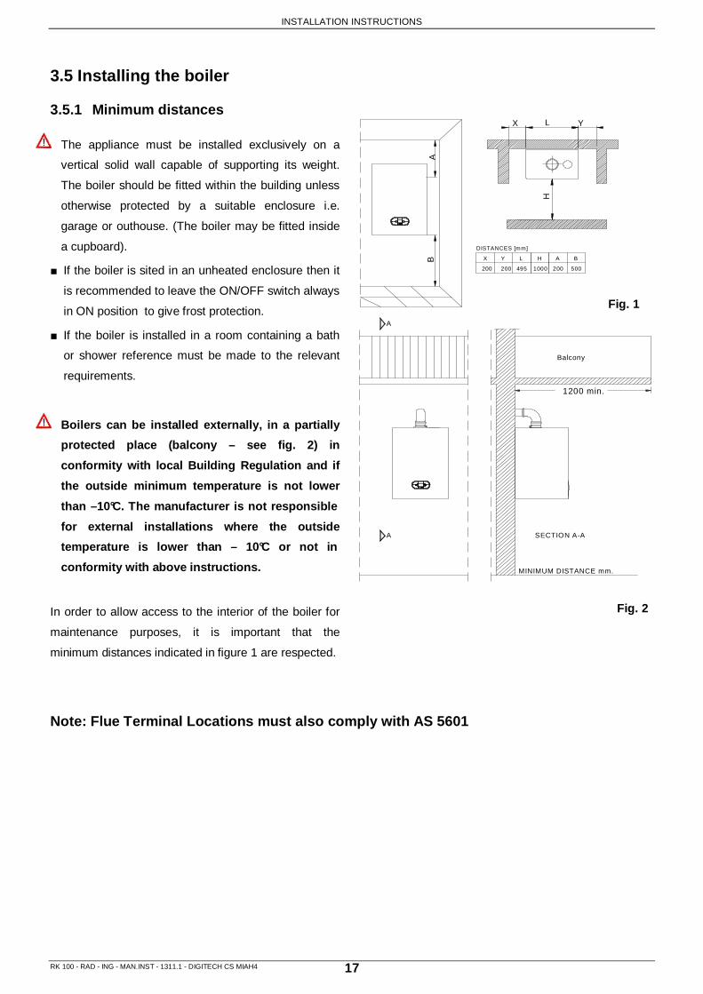
3.5 Installing the boiler 3.5.1 Minimum distances The appliance must be installed exclusively on a
vertical solid wall capable of supporting its weight.
The boiler should be fitted within the building unless
otherwise protected by a suitable enclosure i.e.
garage or outhouse. (The boiler may be fitted inside
a cupboard).
■ If the boiler is sited in an unheated enclosure then it
is recommended to leave the ON/OFF switch always
in ON position to give frost protection.
■ If the boiler is installed in a room containing a bath
or shower reference must be made to the relevant
requirements.
Boilers can be installed externally, in a partiall y
protected place (balcony – see fig. 2) in
conformity with local Building Regulation and if
the outside minimum temperature is not lower
than –10°C. The manufacturer is not responsible
for external installations where the outside
temperature is lower than – 10°C or not in
conformity with above instructions.
In order to allow access to the interior of the boiler for
maintenance purposes, it is important that the
minimum distances indicated in figure 1 are respected.
Note: Flue Terminal Locations must also comply with AS 5601
Fig. 1
Fig. 2

INSTALLATION INSTRUCTIONS
RK 100 - RAD - ING - MAN.INST - 1311.1 - DIGITECH CS MIAH4 18
3.5.2 Fixing the boiler to wall.
The appliance must be installed exclusively on a f lat vertical solid wall capable of supporting its weight .
To avoid the condensate stagnation within the co ndensing exchanger, make sure that the boiler is slightly inclined to the rear (Slope = 4°) to allow the correct draining of the condensate.
To fix the boiler to wall follow this instruction: 1. Check that the spacer A (fig.1) is installed in the boiler to ensure the correct installation slope of 4° co mpared to
the installation wall (fig. 2) and to avoid any condensate stagnation within the condensing exchanger; 2. Fix the external part of the mounting bracket to wall (fig. 1) using proper screw anchors and following the
distances shown in fig.3; 3. Insert the inner guide of the mounting bracket; 4. Hang the boiler onto the special hooks; 5. Once the fixing is completed check that the 4° slope (fi g. 2) is respected;
staffa supporto caldaia
staffa distanziale74304LP
74300LP
767
Fig. 1
Fig. 2 Fig. 3

INSTALLATION INSTRUCTIONS
RK 100 - RAD - ING - MAN.INST - 1311.1 - DIGITECH CS MIAH4 19
3.5.3 Installation Frame - Individual installation
Prior to fixing the appliance to the wall, pay the maximum attention to the installation of the installation frame. The frame must be based on a pl ane surface and it must be perfectly installed at right angels. Incorrect boiler grades can provoke a wrong condensate discharge through the condensate drain pipe and the consequently condensa te stagnation inside the heat exchanger. A correct frame installation assures a counterslope o f about 4° compared to wall perpendicular line.
To install the frame and than the boiler, proceed as follows:
a. Make sure that the wall and the floor form a right angel;
b. Fix the lateral profiles 3 and 4 to the vertical brackets 1 and 2;
c. Fix the vertical brackets 1 and 2 to the horizontal bracket 6;
d. Fix the central and bottom brackets 7 and 8;
e. Once the assembling has been completed, place the frame by fixing it to the wall 9 and to the floor 10;
f. Install the boiler on the frame by using the apposite hooks 11 and complete the installation with the hydraulic
components mounting.
ef d c b af
Fig. 1

INSTALLATION INSTRUCTIONS
RK 100 - RAD - ING - MAN.INST - 1311.1 - DIGITECH CS MIAH4 20
VS
G18
7
VS
4623
0
G
107
RI AI
3.6 Water connections
3.6.1 General warnings
The water connections must be carried out by profe ssionally qualified personnel in accordance with relevant standards.
It is recommended that the system is hot-flushed t o remove any impurities (especially oil and grease) that might compromise the proper working operation of the heating unit, from the pipes and radiators.
Make sure that the central heating pipes are not u sed to earth the electrical system. The pipes are totally unsuitable for this purpose.
The unit should be filled slowly to allow the air to escape through the manual valve fitted as standa rd on the unit; check in addition that all the air has been completely purged from the other parts of the circuit and that the pressure when cold is about 1. 2 ÷ 1.5 bar or in any case the pressure set by the heating engineer.
Connect the outlets of the safety valves to an out let funnel to prevent the boiler room from flooding if these devices cut in. This outlet should preferably be sent to the outside so as to avoid damage to persons or property caused by hot water in the even t that the valve should open.
On systems with a closed expansion tank, the pres sure reducer on the automatic supply unit (where available) should be set to a pressure that will no t exceed the initial design setting. Make sure that while the equipment is working the s ystem pressure does not exceed the working pressure for each component.
It is always advisable to fit the unit in an accessible position to facilitate periodic cleaning operations.
To prevent vibration and noise coming from the system, do not use pipes of reduced diameter, short radius elbows or severe reductions in the cross sections of the water passages.
3.6.2 Hydraulic connections
LEGEND
RI HEATING RETURN Ø1”1/2
AI HEATING FLOW Ø1”1/2
G GAS Ø3/4”
SC CONDENSATE DRAIN Ø25
VS SAFETY VALVE DISCHARGE Ø1/2” Fig. 1

INSTALLATION INSTRUCTIONS
RK 100 - RAD - ING - MAN.INST - 1311.1 - DIGITECH CS MIAH4 21
3.6.3 Central heating circuit In order to prevent scaling or deposits in the primary heat exchanger, the mains supply water to the heating circuit must be treated according to the requirements of local standards. This treatment is indispensable in the case where the circuit is frequently topped-up or when the system is often either partially or fully drained.
The outlet connection of the boiler safety valve must be connected to a discharge trap. The manufacturer will not be held responsible for flooding caused by the operation of the safety valve in the case of system overpressure.
3.6.4 Condensate Drain
Properly connect the siphon condensate collecting the boiler to an exhaust system having adequate slope. Where possible, you should make this link us ing glass collection in order to check for proper condensate drainage avoiding stagnation that could cause hazardous lift the condensate to the boiler.
Check before connecting the condensate trap to the drain pipe, which is ensured by the gradient of boilers as described in paragraphs 3.5.2 and 3.5.3.
The condensate water inflow into the public drainage system, must be in compliance with the municipal standards referring to the sanitary regulations’ wastewaters. The condensate drain system is already pre-installed and connected to each boiler. The condensate drain flexible pipe supplied with the boiler (conforming to UNI EN 677 standard) must be connected to a proper condensate trap. The condensate discharge into the drainage system is allowed providing a condensate trap (siphon) is installed.
It will be care of the planner, in consideration of the system power and the building’s use destination, to value the adoption of acid condensate neutralization systems.
Any condensate discharge pipe work external to the building (or in an unheated part of it) must be insulated to protect against frost. Before switching the boiler On, check the correct condensate discharge. 3.6.5 Condensate neutralization The condensate neutralization system neutralizes the condensate present in boilers and Inox, plastic, glass or ceramic flue exhaust systems. Acid condensate, introduced into the neutralization box, follows a two-steps set course. First phase: nitrates and sulphates filtration through active carbons contained in the first part of the carbon site pipe. Second phase: pH rising. The acidity of the condensate can be controlled through the use of appropriate tools for the determination of Ph, such as the litmus paper. Neutralized condensate can be consequently carried to the drainage system. • Installation instruction a. Assembly of threaded joint to discharge into the drainage system: make a hole D.26-27 mm on long or short
side of the box, to a height of 20 mm from the border, (see fig. 1 – page 22): According to the type of the installation, the hole can be made on longitudinal or transversal side. Put the joint assembled with the washer, from the outside and fix it from the inside with the 3/4” nut.
b. Condensate connection: condensate to be neutralized must be carried to the condensate collector hole (26 mm) on the cover; the rubber holder joint must be connected to the wastewater evacuation system in a disjointed way through the installation of a condensate trap;
c. Box loading: place the bag containing activate carbons in the carbon site pipe corresponding to the condensate collector hole. Pour the content of the granulate bag outside the carbon site pipe.
•••• Maintenance pH parameters must be included between <5,5 – 9,5> Six-monthly. pH determination: Immerse a litmus paper (or an appropriate digital tool) to the condensate near the threaded joint for about 2 seconds and put it onto a white sheet. After about 30 seconds the comparison with the coloured scale will be possible. Neutral point is on the 6,8-7 value; in case of lower value the condensate is acid, in case of a higher value it is basic. No-trated condensate pH can be determinated by immersing the litmus paper inside the carbon site pipe.

INSTALLATION INSTRUCTIONS
RK 100 - RAD - ING - MAN.INST - 1311.1 - DIGITECH CS MIAH4 22
Active carbon: Check the water surface in the box and, if oily traces appear, replace the active carbon bag. Active carbon’s saturated filters can be eliminated as urban waste material and they could be reduced to ashers in water treatment systems. Removing the reagent: Shake well the reagent granulate. The fluid becomes turbid, or rather the chalk or the magnesium sulphate melt and they could be eliminated with water. Annual Active carbon: See six-monthly maintenance. Reagent: Determine the pH values and, if necessary, replace the reagent granulate (see six-monthly maintenance).
Drain the liquid content of the neutralizer box. Remove rubber holder joint and 3/4" nut. Remove all internal
components (including syntetic filter) and wash carefully all internal parts. Reassemble the box by placing the
components in orignal order (see “installation instruction”).
Disposal:
The reagent destination is the dump. The reagent doesn’t contain toxic substances.
For the active carbons’ filter, see “six-montly maintenance”.
Fig. 1

INSTALLATION INSTRUCTIONS
RK 100 - RAD - ING - MAN.INST - 1311.1 - DIGITECH CS MIAH4 23
3.7 Gas Connection
3.7.1 General warnings
The connection to the gas supply must be carried o ut by professionally qualified personnel in
accordance with relevant standards:
When connecting the boiler to the gas supply pipe, only use appropriate washers and gas fittings. Th e
use of hemp, Teflon tape and similar materials is n ot allowed.
The flow rate of the gas meter must be sufficient for the simultaneous use of all devices connected t o
it. Connect the generator gas, according to the reg ulations. The diameter of the gas pipe coming out o f
the generator, is not decisive for the choice of th e diameter of the hose between the unit and the
meter. It must be chosen in function of its length and load losses as a result of calculation by a
qualified technician. Check the nominal pressure pr ovided to the counter as if insufficient can reduce
the power of the generator with inconvenience to th e user.
Before installing the boiler, check the following:
■ The pipe work must have a section appropriate for the flow rates requested and the pipe lengths installed, and
must be fitted with all the safety and control devices provided for by current standards. For Australia refer to AS
5601.
■ The gas supply line must be a minimum of a 22 mm diameter pipe with an uninterrupted supply from meter to
boiler and comply with current standards and regulations.
■ Check the internal and external seals of the gas su pply system.
■ A gas shut-off valve must be installed upstream of the appliance
■ The gas pipe work must have and bigger or equal section to the one of the boiler.
■ Before starting up the boiler, make sure that the type of gas corresponds to that for which the appliance has
been set-up (see gas type label inside the boiler).
■ The gas supply pressure must be between the values reported on the rating plate (see gas type label inside the
boiler).
■ Prior to installation, it is good practice to ensure that there are no machining residues on the gas supply pipe.
■ Conversion of the appliance from natural gas to Propane LPG or vice versa must be carried out by qualified
authorised personnel.

INSTALLATION INSTRUCTIONS
RK 100 - RAD - ING - MAN.INST - 1311.1 - DIGITECH CS MIAH4 24
3.8 Electrical connections
3.8.1 General warnings
The connection to the mains power supply must be c arried out by professionally qualified personnel,
registered in accordance with current legislation a nd authorised by Radiant Bruciatori s.p.a.
Always check to make sure that the appliance has a n efficient earth system. This requirement is only
satisfied if it has been properly connected to an e fficient earth system installed in accordance with the
requirements of current safety standards and carried out by professionally qualified personn el.
This basic safety measure must be checked, verified and carried out by professionally qualified personnel.
In case of doubt, have the electrical system checked by a qualified electrician. The manufacturer will not be held
liable for any damage or injury caused as a result of an inefficient or inexistent earth system;
■ The boiler functions with an alternating current of 230 V and 50 Hz and has maximum power absorption of 180
W. The appliance should be protected by a 3 A fuse. The connection to the mains electricity supply must
be via a single-pole switch, with at least 3 millimetres gap between open contacts, mounted upstream of the
appliance. Make sure that the positions of the live and neutral wires correspond to the wiring diagram;
The power supply cable must not be replaced by the user. If the cable is damaged, turn off the unit
and to replace it, contact a qualified technician. In case of replacement of the power supply cable,
use a minimum cable 3 x 0.75 mm2.
■ Ensure the domestic power supply is checked by a qualified electrician to ensure that it can support the
maximum power absorption of the appliance, as indicated on the rating plate. In particular, make sure that the
cable sizes are adequate for the power absorbed by the appliance;
■ The power supply cable must not be replaced by the user. if the cable is damaged in any way, switch off the
appliance and have the cable replaced by a suitably qualified electrician;
■ When replacing the power supply cable, only use cables of the same characteristics (HO5 VV-F 3x1) with
maximum external Ø 8 mm;
CAUTION: The room thermostat must be dry contact closure. Connecting the 230 V to the terminals
of the room thermostat, will create a permanent damage to the electronic board.
When using an electrical appliance, a few fundament al rules must be observed:
• Do not touch the appliance with damp or wet parts of the body or when barefoot.
• Do not pull on the electric wires.
• Do not leave the appliance exposed to atmospheric elements (rain, sun, etc,) unless these conditions have
been expressly provided for.
• Do not allow the appliance to be used by children or anyone unfamiliar with its operation;

INSTALLATION INSTRUCTIONS
RK 100 - RAD - ING - MAN.INST - 1311.1 - DIGITECH CS MIAH4 25
wiring by the installer
BIPOLAR SWITCH BREAKER GENERAL
brown
yellow/green
blue
IG
power supply 230V 50Hz
L N
2x16A
12
34
AB
Se
Se
Ta
NL
TaS
Fig. 1
3.8.2 Power supply connection
Connect the power supply to the terminal board insi de the control panel as follows:
a. Switch off the power supply at the main switch.
b. Remove the front case panel of the boiler. c. Slacken the screws and remove plate A (see fig. 1).
d. With the plate removed, connect the wires to the terminal board B as follows:
• Connect the earth wire (normally coloured green/yellow) to the terminal marked with the earth symbol “ “.
• Connect the neutral wire (normally coloured blue) to the terminal marked with the letter “N”.
• Connect the live wire (normally coloured brown) to the terminal marked with the letter “L”.
• Terminals identified by the letters: Ta ⇒ Room thermostat
Se ⇒ Outside temperature sensor
When the wires have been connected, place plate “A" back to position.

INSTALLATION INSTRUCTIONS
RK 100 - RAD - ING - MAN.INST - 1311.1 - DIGITECH CS MIAH4 26
Ta
B
LN
Ta
Se
Se
A
TA
CR
SE
Fig. 1
3.8.3 Electrical connections (Option)
Remote control connection – cod. 40-00017
Outdoor temperature sensor cod. 73518LA
3.8.3.1 Remote control (option) connection Connect the wires to the terminal board inside the instrument panel as follows: a. switch off the power supply at the main switch. b. remove the front case panel of the boiler. c. slacken the screws and remove plate A (see fig. 1). d. remove jumper TA -TA from the terminal board B; e. connect the remote control wires on contacts marked as TA-TA;
3.8.3.2 Outside temperature sensor connection (Opti on) Connect the wires to the terminal board inside the instrument panel as follows: a. switch off the power supply at the main switch. b. remove the front case panel of the boiler. c. slacken the screws and remove plate A (see fig. 1). d. connect the outside temperature sensor on contacts marked as SE-SE on the terminal board B ; When the wires have been connected, place plate “A" back to position and then the front case panel.
Note: in the case of simultaneous presence of outdoor temperature sensor and remote control, the electronic board only sends the value of outdoor temperature to the remote device without using it for the modulation. The remote device will use the value for modulation, if necessary. (See the manual of the remote). The communication between the electronic board and the remote control takes place regardless of the mode of operation selection made in the boiler, and once the connection is established, the onboard user interface is
disabled and the display will show the symbol '
Key
SE Outdoor temperature sensor
TA Room thermostat
CR Open Therm Remote control (cod. 40-00017)

INSTALLATION INSTRUCTIONS
RK 100 - RAD - ING - MAN.INST - 1311.1 - DIGITECH CS MIAH4 27
SVZ
SRBNL
SR
brown
blue
PM
BUS+
GNDBUS
TP
CT
0-10V
3.8.4 Electrical connections (Option) Zone Valves Management PCB - Modulating pump Storage cylinder pre-heating timer option - Telep hone control
Key
TP Storage cylinder pre-heating timer option (only if parameter P00 = 2, 3 or 4)
CT Telephone control
PM Modulating pump
SR Heating sensor
SRB Remote boiler Lock-Out indicator Option
SVZ Zone Valves Management PCB (if Remote control is installed)
TAZ 1 ZONE 1 Room thermostat
TAZ 2 ZONE 2 Room thermostat
VZ1 Zone valve 1
VZ2 Zone valve 2
VZR Zone valve Remote control
FC Zone valve limit switch
BUS 0-10V
Bus adjustment input 0-10V
Fig. 1

INSTALLATION INSTRUCTIONS
RK 100 - RAD - ING - MAN.INST - 1311.1 - DIGITECH CS MIAH4 28
3.8.5 3-way valve kit fitted for D.H.W. storage cyl inder connection – D.H.W. sensor and 3-way valve cables connections
• M9 terminal block DHW cylinder sensor : insert the sensor cable inside the control panel inserting terminals 34 and 35. It is not necessary to follow a sequence with the wires.
• M4 terminal block – 3-way valve : connect the 3-way valve motor cable through the Molex terminal. Insert the cable inside the control panel and connect cable terminals to M4 terminal block respecting the following coupling: light-blue – terminal no.9; brown – terminal no.8; black – terminal no.10
Fig. 1

INSTALLATION INSTRUCTIONS
RK 100 - RAD - ING - MAN.INST - 1311.1 - DIGITECH CS MIAH4 29
3.9 Flue connections
3.9.1 General warnings
In order to ensure that the appliance functions co rrectly and efficiently, the flue connection betwee n
the boiler and the flue terminal must be made using original components specifically designed for
condensing boilers.
The flue connection must be carried out in accorda nce with relevant standards.
Prior the installation, check and carefully respec t the current standards. Respect instructions refer ring
to flue terminals positioning on the wall and/or on the roof, minimum distances from windows, wall, ai r
openings…
3.9.2 General instructions
• The boiler is a B23P type with a positive pressure connection to a combustion products discharge system which
intakes the comburent air from the installation sites.
• Thanks to the air-gas premix, the boiler is indipendent from any flue efficiency loss of flue exhaust and
comburent air intake systems. But the maximum flue efficiency loss of the system must not be exceeded to
avoid a reduction of the heat output. Checking the air-gas premix will always guarantee on optimal combustion
and low polluting emissions.
• The maximum flue efficiency loss along the boiler f lue connections is 146 Pascal.
• The sub-horizontal parts of flue exhaust kits must always be installed with a slope (3° slope = 5 mm pip e per
metre) compared to the boiler installed.
• The boiler must be connected to one of the following flue exhaust systems.
• Flue ducts and chimney must be properly dimensioned, planned and produced in compliance with relevant
standards. Their material must be suitable to the final aim with particular resistance to the corrosion, internally
smooth and hermetic sealed. Particularly, joints must be condensate tight. To avoid that the condensate
produced inside the flue hood flows into the boiler, proper drain points connected to a condensate trap must be
previewed.
.

INSTALLATION INSTRUCTIONS
RK 100 - RAD - ING - MAN.INST - 1311.1 - DIGITECH CS MIAH4 30
3.9.3 Flue kit systems
3.9.3.1 Flue type - KIT EK 100 – cod. 82278LA
Horizontal flue kit Ø100 mm in polypropylene
Discharges exhaust fumes and draws air from atmosphere.
800
190
MAXIMUM FLUE LENGTH
The maximum flue length (linear equivalent) is obtained:
a. Through the sum of individual components flue lengths (linear equivalent) that must be lower than 8 m;
b. Through the sum of individual components’ flue efficiency losses, that must be lower than 146 Pa.
The maximum flue length can be obtained according to the following table:
Description Equivalent lenght m
Flue efficiency loss Pa
Extension Ø100 L = 1000 mm MF polypropylene 1 5.8
Vertical connector Ø100 w/test point MF polypropylene 0.5 2.9
90° Flue bend Ø100 MF polypropylene 3 17.5
45° Flue bend Ø100 MF polypropylene 1.4 7.8
Fig. 1

INSTALLATION INSTRUCTIONS
RK 100 - RAD - ING - MAN.INST - 1311.1 - DIGITECH CS MIAH4 31
3.9.3.2 Flue type KIT FK 100 – cod. 82280LP Vertical flue kit Ø100 mm in polypropylene . Discharges exhaust fumes and draws air directly from high Level.
Ø100
800
MAXIMUM FLUE LENGTH
The maximum flue length (linear equivalent) is obtained:
a. Through the sum of individual components flue lengths (linear equivalent) that must be lower than 15 m;
b. Through the sum of individual components’ flue efficiency losses, that must be lower than 146 Pa.
The maximum flue length can be obtained according to the following table:
Description Equivalent lenght m
Flue efficiency loss Pa
Extension Ø100 L = 1000 mm MF polypropylene 1 5.8
Vertical connector Ø100 w/test point MF polypropylene 0.5 2.9
90° Flue bend Ø100 MF polypropylene 3 17.5
45° Flue bend Ø100 MF polypropylene 1.4 7.8
Fig. 1

INSTRUCTIONS FOR THE FIRST TIME IN SERVICE
RK 100 - RAD - ING - MAN.INST - 1311.1 - DIGITECH CS MIAH4 32
4. COMMISSIONING THE APPLIANCE
4.1 General warnings
The following operations must be carried out by pr ofessionally qualified personnel, registered in accordance with current legislation and authorised by Radiant Bruciatori s.p.a.
The boiler leaves the factory pre-set and tested f or either Natural Gas or Propane LPG. Nevertheless, when starting the boiler for the first time, make s ure that the information on the rating plate corresponds to the type of gas being supplied to th e boiler.
It is recommended that the system is hot-flushed t o remove any impurities (especially oil and grease) that might compromise the proper working operation of the heating unit, from the pipes and radiators.
Once the system has been filled and the necessary adjustments made, remember to tighten the screws of the gas valve test point and make sure th at there are no gas leaks from the test point and from any pipe fittings upstream of the gas valve.
4.2 Preliminary operations
Switching the boiler on for the first time means checking that the installation, regulation and operation of the appliance are correct:
• If the gas supply system is newly installed, then the air present in the pipes can cause the boiler not to light at the first attempt. A number of attempts may be required in order to light the boiler;
• Check that the data on the data plate corresponds to that of the mains supply networks (gas, electricity, water);
• Check that the power supply voltage to the boiler complies with the data plate (230 V – 50 Hz) and that the live, neutral and earth wires are connected properly. Also make sure that the earth connection is sound;
• Check the seals on the gas supply pipe from the mains, and make sure that the meter does not register any flow of gas;
• Open the gas feed valve and make sure that there are no gas leaks from pipe fittings upstream of the boiler (the burner’s gas connection must be checked with boiler in function);
• Check that the gas supply is correctly sized for the flow rate required by the boiler and that it is fitted with all the safety and control devices as lay down by current regulations;
• Check that the supply of combustion air and exhaust and condensate discharge systems are functioning correctly and in line with current law and national and local standards;
• Check for the presence of permanent aeration/ventilation openings as required by current law for the type of appliances installed;
• Check that the flue duct and its connections to the terminal/chimney comply with the requirements of current law and national and local standards for the type of appliances installed;
• Make sure that any central heating shut-off valves are open;
• Check that the boiler is sloped of 3°/4° toward the back side. Check that the condensate drain system, including outside the boiler (flue system condensate collection devices), allows the condensate to flow freely to the collection devices. If the condensate is discharged to the domestic drainage system, install an inspection trap in the condensate system prior to it entering the drainage system to interrupt the continuity between the two systems;
• Check that there are no exhaust fumes discharged into the system itself;
• Check that there are no flammable materials or liquids in the immediate vicinity of the boiler;
• Check that circulating pumps freely rotate. Unscrew the inspection screw and verify with a flat screwdriver that the impeller works without obstructions. Prior to loosen or remove the circulating pump cap, protect the electrical devices below from possible leaks of water.
INSTRUCTIONS FOR THE FIRST TIME IN SERVICE
RK 100 - RAD - ING - MAN.INST - 1311.1 - DIGITECH CS MIAH4 33
4.3 Filling the system
4.3.1 General warnings
Check the properties of the water supply and instal l the appropriate treatment devices if the mains water has a hardness rating more than 15°F i n order to prevent scaling and eventual damage to th e D.H.W heat exchanger.
Use only clean tap water to fill the system. If the system is filled with frost protection chemi cal agents, the installation of a hydraulic compens ator is necessary to separate the central heating circui t from the domestic hot water circuit.
Once the water pipes have been connected, Before switching the power supply ON, close the gas feed valve and fill the system as follows:
• Check that the circulating pump runs freely;
• Check that the plug of the air vent valve has been slackened slightly to allow air to escape from the system;
• Close the draining tap and open the external filling loop valve. Use a pressure gauge to check that the system pressure reaches 1.2 ÷ 1.5 bar.
• make sure that the external filling loop valve is perfectly closed.
• Unscrew the plug on the pump to remove any trapped air, check that the pump is free then re-tighten it when water starts to flow out.
• Open the air vents on the radiators and monitor the air evacuation process. When water starts to flow out of the radiators, close the air vents.
• If, after the above operations, there is a pressure reduction, re-open the external filling loop valve until the pressure gauge reaches 1.2 ÷ 1.5 bar.
• On completion, make sure that the filling loop is t urned off ;

INSTRUCTIONS FOR THE FIRST TIME IN SERVICE
RK 100 - RAD - ING - MAN.INST - 1311.1 - DIGITECH CS MIAH4 34
4.3.2 System water features To ensure that the appliance functions correctly, t he following fundamental rules must be observed:
1. make sure that the system doesn’t present any leaks and that the bigger ones or the most evident are removed;
2. In presence of an automatic filling system, a liter counter must be installed to know precisely the leaks entity.
3. Softened water must be used to fill up the system in order to reduce the total hardness. The water must be also conditioned to maintain the pH value within the standard limit to avoid corrosion phenomena.
4. In case of new boilers or boiler replacement, the system must be equipped of efficient devices which provide the boiler against air and impurities: Y filters, micro impurities and micro air-bubbles’ separators;
5. Make sure that the system water is not discharged during the current maintenance operations even if quantities are apparently insignificant: for example the system must be equipped with apposite shut-off valves for the filters’ cleaning.
6. Prior to connect a new boiler to the system, always proceed with the system water analysis to check if water parameters indicate the necessity to drain the system, to use the water already present in the system or to proceed with a chemical system flushing by using the running water with the addition of a detergent in case the system is particularly dirty or obstructed, and to consequently fill up the system with new treated water.
Water treatment In order to preserve the primary heat exchanger’s integrity and always guarantee optimal thermal exchanges, the mains supply water to the primary circuit, circulating inside the condensing boiler heat exchanger, must present long-term definite and constant features.Following preparation and maintenance operations, in compliance with the current standard UNI-CTI 8065, are fundamental: • flushing up the system; • check the system water features; The choice of the water treatment type must be made according to the water features, the system type a nd the pureness limit requested. Oxygen A certain quantity of Oxygen always enters in the system, both in the phase of filling and during the system use, in case of water recovery or in presence of hydraulic components without barriers to the oxygen. Oxygen by reacting with the steel creates corrosion and muds formation. While the primary heat exchanger is made of stainless steel, which is not subjected to corrosion, muds created inside the carbon steel system will deposit in warm parts included the primary heat exchanger. The result will be the reduction of the boiler capacity and the obstruction of the primary heat exchanger’s active parts by provoking damages to the boiler. Precautions to limit this phenomenon are: - Mechanical systems: a combined air vent and a deslimer correclty installed reduce the Oxygen quantity circulating in the system. - Chemical systems: additives allow the Oxygen to remain dissolved in the water. Hardness The hardness of the filling or recovery water brings a certain quantity of calcium in the system. Calcium adheres on warm parts included the primary heat exchanger. The result is the reduction of the boiler capacity and the obstruction of the primary heat exchanger’s active parts by provoking damages to the boiler. In case the filling or recovery water of the system is not within the values reported here below, it must be sweetened. Additional additives can be used to keep Calcium in solution. The water hardness must be controlled and registered regularly.
A chemical treatment is necessary if the limit of values above is exceeded.
The choice of the water treatment type must be made according to the water features, the system type a nd the pureness limit requested.
Acidity 6,6 < pH < 8,5
Conductivity < 400 µS/cm (a 25°C)
Chlorides < 125 mg/l
Iron < 0,5 mg/l
Copper < 0,1 mg/l

INSTRUCTIONS FOR THE FIRST TIME IN SERVICE
RK 100 - RAD - ING - MAN.INST - 1311.1 - DIGITECH CS MIAH4 35
4.4 Filling the condensate trap
The condensation trap must be pre-
filled when starting the boiler for the
first time in order to prevent flue
gases from flowing back through the
trap.
The filling operation is carried out as
follows (fig. 1 previous page):
• Remove plug T and fill the trap S
three quarters full with water.
• Replace plug T and connect the
drainpipe P.
Note: It is advisable, after the first
few months of operation, to clean the
condensate trap from deposits
resulting from the first passage of
condensate within the technical
components of the boiler. Such
deposits may cause the malfunction
of the siphon. Fig. 1
SB
T
T
B
S

INSTRUCTIONS FOR THE FIRST TIME IN SERVICE
RK 100 - RAD - ING - MAN.INST - 1311.1 - DIGITECH CS MIAH4 36
4.5 Frost Protection 4.5.1 General warnings
The boiler is protected from freezing by electronic board settings and special functions that provide the starting of the burner to heat all the interested parts, when their temperature drops below the minimum preset values, protecting the boiler up to an external temperature of -10°C.
The device operates as follows:
• The heating circuit water temperature drops below 5 °C, the burner is automatically switched ON until the water reaches a temperature of 30°C.
• The domestic hot water temperature drops below 4°, the burner is automatically switched ON until the water reaches a temperature of 8°C.
The system operates even if the boiler is in OFF mo de, as long as it is electrically powered (230 V) a nd the gas supply is open.
In case of long periods of inactivity, it is recomm ended to empty the boiler and the hydraulic system. Warning for the service technician
In case of a boiler locked out because of freezing, before putting it into operation, make sure that any part is blocked by ice (heat exchanger, pump, etc.). Warning for the installer
In case of an outdoor boiler installation, where temperatures can drop below -10°C, it is recommended to fill the hydraulic system with an antifreeze inhibitor (see below Table for the dilution percentage) and to install a Heating elements kit (code 82259LP).
4.5.2 Heating elements Kit installation and wiring Please proceed as follows:
a. Switch OFF the power supply at the main switch; b. Position the 4 resistances onto the heating flow pipe, heating return pipe, (with the exception of the gas
pipe). c. Protect the pipes with isolating material; d. Connect the thermostat to the heating flow pipe using the supplied clip; e. Connect the power supply cables to the terminal board located onto the control panel and following the
wiring instruction; f. Secure the cables between them using the supplied clamps.
Table
Antifreeze Temperature Ethylene glycol
(%) volume freezing point
(°C) boiling point
(°C) 10 - 4 101 20 - 10 102 30 - 17 104 40 - 27 106 50 - 40 109 60 - 47 114
Recommended Glycol 20% percentage for temperatures up to -10°C.

INSTRUCTIONS FOR THE FIRST TIME IN SERVICE
RK 100 - RAD - ING - MAN.INST - 1311.1 - DIGITECH CS MIAH4 37
4.6 Starting up the boiler
Once the system has been filled, proceed as follows:
• Check that the exhaust duct is free from obstructions and correctly connected to the flue exhaust system;
• Switch on the power supply to the boiler;
• only for the first start-up, the ignition system will automatically start the ’System purging’ function. The function code F33 will appear on the display. When the function is active, the pump circulates but the burner will not start for 5 minutes. The starting of the boiler is enabled only once the purging cycle has been completed.
• Open the gas feed valve;
• Use button to select the WINTER mode. The
symbol will light up (fixed light) to indicate the selected operation mode.
• In case of RS version with remote storage cylinder,
use button to select WINTER-SUMMER mode.
The symbol will light up (fixed light) to indicate the selected operation mode.
• The automatic ignition system will then light the burner.
• In case of flame failure, the ignition system repeats the ignition procedure after the fan-overrun cycle (20 sec). It may be necessary to repeat the operation in order to remove all the air from the pipes. To repeat the operation, wait approximately 5 seconds from the last ignition attempt before resetting the error code
E01 (pressing the reset button ‘ ’).
• With the boiler ignited, if the system still emits noises, the operations must be repeated until all the air has been removed;
• Check the pressure in the system. If the pressure has fallen, re-open the filling tap until the pressure gauge reads 1.2 ÷ 1.5 bar on completion, close the filling tap.
• Unscrew the aluminium plug and insert an analyser in the exhaust sampling point PF (see fig. 1) to check the CO2 value. Make sure that the value complies with that reported in table 1;
• If the CO2 value does not correspond to the specified value, carry out adjustment as provided in paragraph “5.5.1 – Max. power supply regulation - CO2 value” ;
Table n°1
Gas type CO 2 % Natural gas 9.4
Propane LPG 10.3
V
PF
Fig. 1
Fig. 2

REGULATION INSTRUCTIONS
RK 100 - RAD - ING - MAN.INST - 1311.1 - DIGITECH CS MIAH4 38
5. REGULATING THE APPLIANCE
5.1 Parameters table PARAMETER
N° TYPE OF OPERATION PARAMETER VALUE FUNCTION
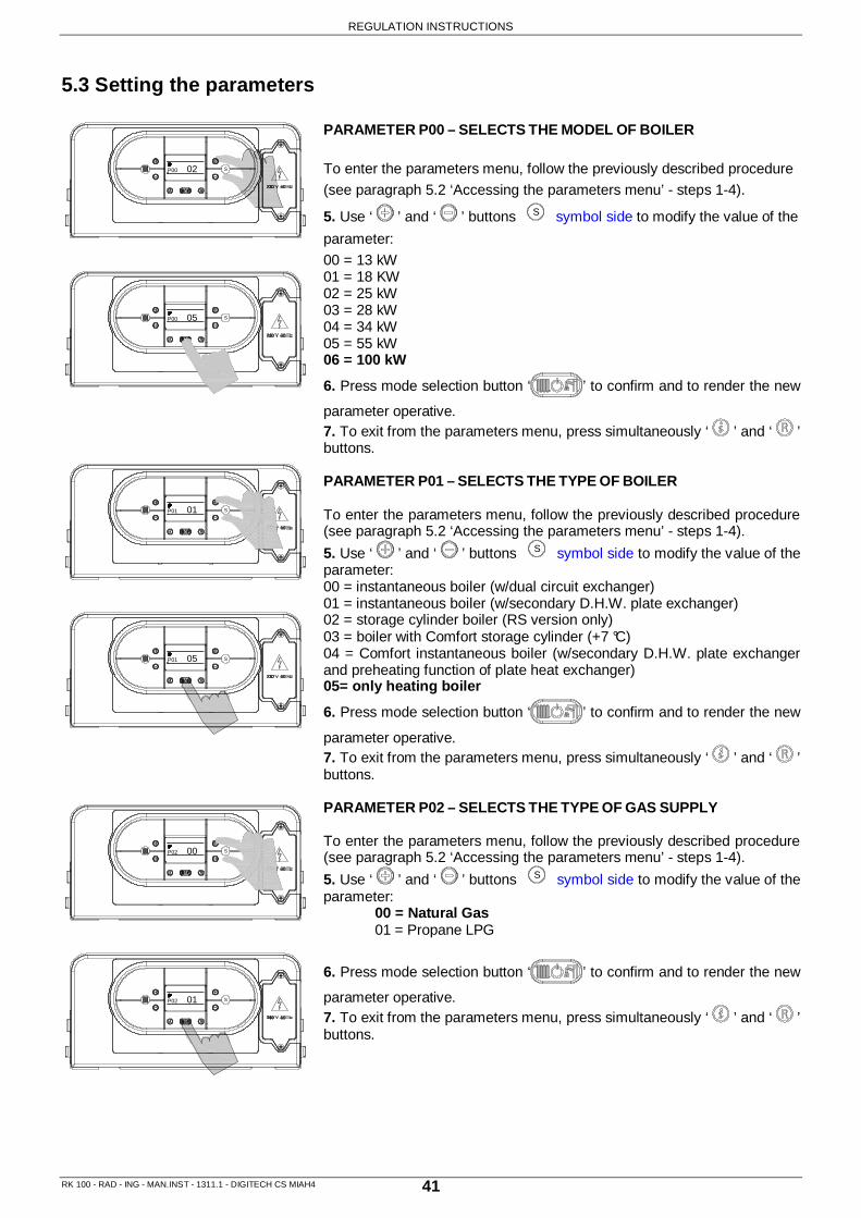
P00 Selects the model of boiler 00-06
00 = 13 kW 01 = 18 KW 02 = 25 kW 03 = 28 kW 04 = 34 kW 05 = 55 kW
06 = 100 kW
P01 Selects the type of boiler 00-05
00 = Istantaneous boiler (w/dual circuit exchanger) 01 = Istantaneous boiler (w/secondary D.H.W. plate exch.) 02 = Storage cylinder boiler 03 = Boiler with Comfort storage cylinder 04 = Comfort istantaneous boiler (w/sec. D.H.W. plate exch.) 05 = Only heating boiler
P02 Selects the type of gas supply 00 01
Natural gas Propane LPG
P03 Sets the central heating temperature 00 01
Standard (30-80 °C) Reduced (25-45 °C)
P04 Heating output rising time 00-04
00 = 0 seconds (Disabled) 01 = 50 seconds (Default)
02 = 100 seconds 03 = 200 seconds 04 = 400 seconds
P05 Water hammer prevention function 00 01
Off On
P06 D.H.W priority function
(RS version only - with connection to a remote storage cylinder)
00 01
Off On
P07 Central heating timer 00 - 90 Displayed in multiples of 5
seconds (default value 36 x 5 = 180”)
P08 Central heating pump overrun timer 00 - 90 Displayed in multiples of 5
seconds (default value 36 x 5 = 180”)
P09
D.H.W/Storage cylinder pump overrun timer
(RS version only - with connection to a remote storage cylinder)
00 - 90 Displayed in multiples of 5
seconds (default value 18 x 5 = 90”)
P10 Sets the minimum fan speed 33 - P11 Displayed in hertz (1Hz = 30 rpm)
P11 Sets the maximum fan speed P10 - 203 Displayed in hertz (1Hz = 30 rpm)

REGULATION INSTRUCTIONS
RK 100 - RAD - ING - MAN.INST - 1311.1 - DIGITECH CS MIAH4 39
PARAMETER N° TYPE OF OPERATION PARAMETER
VALUE FUNCTION
P12 Sets the minimum fan speed (central heating) 33 - P13 Displayed in hertz
(1Hz = 30 rpm)
P13 Sets the maximum fan speed (central heating) P12 - 203 Displayed in hertz
(1Hz = 30 rpm)
P14 Sets the ignition sequence 33 - 203 Displayed in hertz (1Hz = 30 rpm)
P15 Legionella prevention function
(RS version only - with connection to a remote storage cylinder)
00 01
Off On
P16 Sets the climatic compensation curve (w/outdoor temperature sensor only installation)
00-30 See the graph in the parameter setting explanation
P17 Sets the temperature measurement unit 00 01
°C °F
P18 Sets the 0-10V industrial bus piloting 00-02
00 = Disabled 01 = Flow temperature control
mode 02 = Burner output control mode
P19 Central heating minimum set point 20 - 40 Displayed in °C
P20 Central heating maximum set point 40 - 90 Displayed in °C
P21 D.H.W maximum set point
(RS version only - with connection to a remote storage cylinder)
45 - 75 Displayed in °C
P22 ∆T set point T° flow / T° return
(w/modulating pump and return temperature sensor connected only)
00 10 - 40
00 = Disabled Displayed in °C
P23 Modulating pump minimum speed
(w/modulating pump and return temperature sensor connected only)
50 - 70 Displayed in percentage
P24 Modulating pump maximum speed (w/modulating pump and return temperature
sensor connected only) 70 - 100 Displayed in percentage
P25 ∆T timing T° flow / T° return
(w/modulating pump and return temperature sensor connected only)
20 - 100 Displayed in seconds
NOTES: P01 “05” default value for only heating boiler - R version; “02” value for only heating boiler +
connections to a remote storage cylinder - RS version; P04 This parameter allows to modify the time the boiler takes (in heating mode) to reach the
maximum power set. P10, P11, P12 These parameters are automatically set according to the output value set in Parameter P00. P13 The maximum boiler power, in heating mode, can be set according to the paragraph “5.4.2
Heating Power (kW) – Fan frequency (Hz) diagram “ P06, P09, P15, P21 Only for RS version with connection to a remote storage cylinder. P02 The boiler is NOT approved for LPG (G30 – G31);

REGULATION INSTRUCTIONS
RK 100 - RAD - ING - MAN.INST - 1311.1 - DIGITECH CS MIAH4 40
5.2 Accessing the parameters menu
To modify the preset values of the parameters reported in the previous table, open the parameter settings menu as follows:
1. Place mode selection button ‘ ’ in OFF position, visualized by symbol; 2. Keep pressed ‘ ’ and ‘ ’ buttons simultaneously and wait for symbol and ‘P00’, to appear on the display. 3. Release buttons ‘ ’ and ‘ ’; 4. Use ‘ ’ and ‘ ’ buttons of heating temperature
setting to select the parameter to modify;
Adjust the value of the parameter using the procedure described in the following pages.
2P00
P01 1
S
S
S
REGULATION INSTRUCTIONS
RK 100 - RAD - ING - MAN.INST - 1311.1 - DIGITECH CS MIAH4 41
5.3 Setting the parameters PARAMETER P00 – SELECTS THE MODEL OF BOILER
To enter the parameters menu, follow the previously described procedure
(see paragraph 5.2 ‘Accessing the parameters menu’ - steps 1-4).
5. Use ‘ ’ and ‘ ’ buttons S symbol side to modify the value of the
parameter:
00 = 13 kW 01 = 18 KW 02 = 25 kW 03 = 28 kW 04 = 34 kW 05 = 55 kW 06 = 100 kW
6. Press mode selection button ‘ ’ to confirm and to render the new
parameter operative. 7. To exit from the parameters menu, press simultaneously ‘ ’ and ‘ ’ buttons. PARAMETER P01 – SELECTS THE TYPE OF BOILER To enter the parameters menu, follow the previously described procedure (see paragraph 5.2 ‘Accessing the parameters menu’ - steps 1-4).
5. Use ‘ ’ and ‘ ’ buttons S symbol side to modify the value of the parameter: 00 = instantaneous boiler (w/dual circuit exchanger) 01 = instantaneous boiler (w/secondary D.H.W. plate exchanger) 02 = storage cylinder boiler (RS version only) 03 = boiler with Comfort storage cylinder (+7 °C) 04 = Comfort instantaneous boiler (w/secondary D.H.W. plate exchanger and preheating function of plate heat exchanger) 05= only heating boiler
6. Press mode selection button ‘ ’ to confirm and to render the new
parameter operative. 7. To exit from the parameters menu, press simultaneously ‘ ’ and ‘ ’ buttons. PARAMETER P02 – SELECTS THE TYPE OF GAS SUPPLY To enter the parameters menu, follow the previously described procedure (see paragraph 5.2 ‘Accessing the parameters menu’ - steps 1-4).
5. Use ‘ ’ and ‘ ’ buttons S symbol side to modify the value of the parameter: 00 = Natural Gas 01 = Propane LPG
6. Press mode selection button ‘ ’ to confirm and to render the new
parameter operative. 7. To exit from the parameters menu, press simultaneously ‘ ’ and ‘ ’ buttons.
S
S
S
S
S
S
P00 05
P00 02
01P01
05P01
00P02
01P02

REGULATION INSTRUCTIONS
RK 100 - RAD - ING - MAN.INST - 1311.1 - DIGITECH CS MIAH4 42
PARAMETER P03 – SETS THE CENTRAL HEATING TEMPERATURE To enter the parameters menu, follow the previously described procedure (see paragraph 5.2 ‘Accessing the parameters menu’ - steps 1-4). 5. Use ‘ ’ and ‘ ’ buttons S symbol side to modify the value of the parameter: 00 = standard (30-80°C) 01 = reduced (25-45°C) for under-floor heating
6. Press mode selection button ‘ ’ to confirm and to render the new
parameter operative. 7. To exit from the parameters menu, press simultaneously ‘ ’ and ‘ ’ buttons. PARAMETER P04 – HEATING OUTPUT RISING TIME This parameter is used to set the time the boiler takes to reach the maximum power set, during the starting up. To enter the parameters menu, follow the previously described procedure (see paragraph 5.2 ‘Accessing the parameters menu’ - steps 1-4). 5. Use ‘ ’ and ‘ ’ buttons S symbol side to modify the value of the parameter: 00 = 0 seconds (disabled) 01 = 50 seconds (default) 02 = 100 seconds 03 = 200 seconds 04 = 400 seconds
6. Press mode selection button ‘ ’ to confirm and to render the new
parameter operative. 7. To exit from the parameters menu, press simultaneously ‘ ’ and ‘ ’ buttons. PARAMETER P05 – WATER HAMMER PREVENTION FUNCTION Activating this function, the D.H.W contact is delayed for 2 seconds. To enter the parameters menu, follow the previously described procedure (see paragraph 5.2 ‘Accessing the parameters menu’ - steps 1-4). 5. Use ‘ ’ and ‘ ’ buttons S symbol side to modify the value of the parameter: 00 = Off 01 = On
6. Press mode selection button ‘ ’ to confirm and to render the new
parameter operative. 7. To exit from the parameters menu, press simultaneously ‘ ’ and ‘ ’ buttons.
P05 01
P05 00
P04 02
P04 01
00P03
01P03
S
S
S
S
S
S

REGULATION INSTRUCTIONS
RK 100 - RAD - ING - MAN.INST - 1311.1 - DIGITECH CS MIAH4 43
PARAMETER P06 – D.H.W PRIORITY FUNCTION N.B. RS version only - with connection to a remote storage cylinder This parameter is used to maintain the diverter valve on D.H.W mode for a time equal to the post-circulation, keeping hot the secondary heat exchanger. To enter the parameters menu, follow the previously described procedure (see paragraph 5.2 ‘Accessing the parameters menu’ - steps 1-4).
5. Use ‘ ’ and ‘ ’ buttons S symbol side to modify the value of the parameter: 00 = Off 01 = On
6. Press mode selection button ‘ ’ to confirm and to render the new
parameter operative. 7. To exit from the parameters menu, press simultaneously ‘ ’ and ‘ ’ buttons. PARAMETER P07 – CENTRAL HEATING TIMER This parameter is used to set the minimum time in which the burner is kept switched off, once the heating flow temperature has exceeded the temperature set by the user. To enter the parameters menu, follow the previously described procedure (see paragraph 5.2 ‘Accessing the parameters menu’ - steps 1-4).
5. Use ‘ ’ and ‘ ’ buttons S symbol side to modify the value of the parameter within the prescribed limits (displayed in multiples of 5 seconds): min = 00 max = 90 For ex.: 90 = 90 x 5” = 450” (7,5 min) The default value is 36 = 180” = 3 min
6. Press mode selection button ‘ ’ to confirm and to render the new
parameter operative. 7. To exit from the parameters menu, press simultaneously ‘ ’ and ‘ ’ buttons. PARAMETER P08 – CENTRAL HEATING PUMP OVERRUN TIMER This parameter is used to set the pump functioning time, in heating mode, after switching off the main burner for the intervention of the room thermostat. To enter the parameters menu, follow the previously described procedure (see paragraph 5.2 ‘Accessing the parameters menu’ - steps 1-4).
5. Use ‘ ’ and ‘ ’ buttons S symbol side to modify the value of the parameter within the prescribed limits (displayed in multiples of 5 seconds): min = 00 max = 90 For ex.: 90 = 90 x 5” = 450” (7,5 min) The default value is 36 = 180” = 3 min
6. Press mode selection button ‘ ’ to confirm and to render the new
parameter operative. 7. To exit from the parameters menu, press simultaneously ‘ ’ and ‘ ’ buttons.
S
S
S
S
S
S
P06 01
P06 00
36P07
48P07
36P08
48P08

REGULATION INSTRUCTIONS
RK 100 - RAD - ING - MAN.INST - 1311.1 - DIGITECH CS MIAH4 44
PARAMETER P09 – D.H.W/STORAGE CYLINDER PUMP OVERRUN TIMER N.B. RS version only - with connection to a remote storage cylinder This parameter is used to set the pump functioning time, in D.H.W mode, after closing the water tap. To enter the parameters menu, follow the previously described procedure (see paragraph 5.2 ‘Accessing the parameters menu’ - steps 1-4).
5. Use ‘ ’ and ‘ ’ buttons S symbol side to modify the value of the parameter within the prescribed limits (displayed in multiples of 5 seconds): min = 00 max = 90 For ex.: 90 = 90 x 5” = 450” (7,5 min) The default value is 18 = 90” = 1.5 min
6. Press mode selection button ‘ ’ to confirm and to render the new
parameter operative. 7. To exit from the parameters menu, press simultaneously ‘ ’ and ‘ ’ buttons. PARAMETER P10 – SETS THE MINIMUM FAN SPEED This parameter is used to set the minimum fan speed which corresponds to the minimum burner output. To enter the parameters menu, follow the previously described procedure (see paragraph 5.2 ‘Accessing the parameters menu’ - steps 1-4).
5. Use ‘ ’ and ‘ ’ buttons S symbol side to modify the value of the parameter within the prescribed limits (displayed in Hertz): min = 33 Hz max = Value set in parameter P11 The default value is set according to the output value set in Parameter P00.
6. Press mode selection button ‘ ’ to confirm and to render the new
parameter operative. 7. To exit from the parameters menu, press simultaneously ‘ ’ and ‘ ’ buttons. PARAMETER P11 – SETS THE MAXIMUM FAN SPEED This parameter is used to set the maximum fan speed which corresponds to the maximum burner output. To enter the parameters menu, follow the previously described procedure (see paragraph 5.2 ‘Accessing the parameters menu’ - steps 1-4).
5. Use ‘ ’ and ‘ ’ buttons S symbol side to modify the value of the parameter within the prescribed limits (displayed in Hertz): min = Value set in parameter P10 max = 203 Hz The default value is set according to the output value set in Parameter P00.
6. Press mode selection button ‘ ’ to confirm and to render the new
parameter operative. 7. To exit from the parameters menu, press simultaneously ‘ ’ and ‘ ’ buttons.
P11
P11 170
P10 61
P10 60
18P09
36P09
S
S
S
S
S
S171

REGULATION INSTRUCTIONS
RK 100 - RAD - ING - MAN.INST - 1311.1 - DIGITECH CS MIAH4 45
PARAMETER P12 – SETS THE MINIMUM FAN SPEED (CENTRAL HEATING) This parameter is used to set the minimum fan speed in heating mode, which corresponds to the minimum burner output during a heating mode request. To enter the parameters menu, follow the previously described procedure (see paragraph 5.2 ‘Accessing the parameters menu’ - steps 1-4).
5. Use ‘ ’ and ‘ ’ buttons S symbol side to modify the value of the parameter within the prescribed limits (displayed in Hertz): min = 33 Hz max = Value set in parameter P13 The default value is set according to the output value set in Parameter P00.
6. Press mode selection button ‘ ’ to confirm and to render the new
parameter operative. 7. To exit from the parameters menu, press simultaneously ‘ ’ and ‘ ’ buttons. PARAMETER P13 – SETS THE MAXIMUM FAN SPEED (CENTRAL HEATING) This parameter is used to set the maximum fan speed in heating mode, which corresponds to the maximum burner output during a heating mode request [see paragraph 5.5 Heating output (kW) – Fan frequency (Hz) diagram]. To enter the parameters menu, follow the previously described procedure (see paragraph 5.2 ‘Accessing the parameters menu’ - steps 1-4).
5. Use ‘ ’ and ‘ ’ buttons S symbol side to modify the value of the parameter within the prescribed limits (displayed in Hertz): min = Value set in parameter P12 max = 203 Hz The default value is set according to the output value set in Parameter P00.
6. Press mode selection button ‘ ’ to confirm and to render the new
parameter operative. 7. To exit from the parameters menu, press simultaneously ‘ ’ and ‘ ’ buttons. PARAMETER P14 – SETS THE IGNITION SEQUENCE This parameter is used to set the fan speed during the starting up of the boiler. To enter the parameters menu, follow the previously described procedure (see paragraph 5.2 ‘Accessing the parameters menu’ - steps 1-4).
5. Use ‘ ’ and ‘ ’ buttons S symbol side to modify the value of the parameter within the prescribed limits (displayed in Hertz): min = Value set in parameter P10 max = 203 Hz The default value is set according to the output value set in Parameter P00.
6. Press mode selection button ‘ ’ to confirm and to render the new
parameter operative. 7. To exit from the parameters menu, press simultaneously ‘ ’ and ‘ ’ buttons.
S
S
S
S
S
S
P12
P12
P13
P13
90P14
91P14
60
61
170
171

REGULATION INSTRUCTIONS
RK 100 - RAD - ING - MAN.INST - 1311.1 - DIGITECH CS MIAH4 46
PARAMETER P15 – LEGIONELLA PREVENTION FUNCTION N.B. RS version only - with connection to a remote storage cylinder To enter the parameters menu, follow the previously described procedure (see paragraph 5.2 ‘Accessing the parameters menu’ - steps 1-4).
5. Use ‘ ’ and ‘ ’ buttons S symbol side to modify the value of the parameter: 00 = Off 01 = On
6. Press mode selection button ‘ ’ to confirm and to render the new
parameter operative. 7. To exit from the parameters menu, press simultaneously ‘ ’ and ‘ ’ buttons.
PARAMETER P16 – SETS THE CLIMATIC COMPENSATION CURVE (w/outdoor temperature sensor only installation) N.B. With outdoor temperature sensor only The installation of an outdoor temperature sensor (see “6.8 ‘Electrical connections”) allows to automatically modify the flow temperature in accordance to the outdoor temperature. The factor governing the correction is the Kd thermoregulation value, indicating the flow temperature range selected (fig.1). The selection of the compensation curve is determined by the maximum flow temperature Tm and the minimum outdoor temperature Te taking into consideration the house insulation degree.
The values of the flow temperature Tm, refer to standard 30-80 °C appliances or 25-45 °C for under-floor heating systems. The type of appliance can be set using parameter P03. To enter the parameters menu, follow the previously described procedure (see paragraph 5.2 ‘Accessing the parameters menu’ - steps 1-4) and select parameter P16.
5. Use ‘ ’ and ‘ ’ buttons S symbol side to modify the value of the parameter within the range of setting from 00 to 30. The value corresponds to the graph curves in figure n.1.
6. Press mode selection button ‘ ’ to confirm and to render the new
parameter operative. 7. To exit from the parameters menu, press simultaneously ‘ ’ and ‘ ’ buttons.
Te (°C)353025201510
75
8045 MAX
Tm (°C)
50-5-10
65
55
60
50
40
45
35
30
30
-15-20
25 MIN
35
70
Kd = 0
Kd = 5
Kd = 10
Kd = 15Kd = 20 Kd = 25 Kd = 30
Note: in the case of simultaneous presence of outdoor temperature sensor and remote control, the electronic board only sends the value of outdoor temperature to the remote device without using it for the modulation. The remote device will use the value for modulation, if necessary. (See the manual of the remote). The communication between the electronic board and the remote control takes place regardless of the mode of operation selection made in the
boiler, and once the connection is established, the onboard user interface is disabled and the display will show the symbol '
Fig. 1
P16 20
P16 15
00P15
01P15
S
S
S
S

REGULATION INSTRUCTIONS
RK 100 - RAD - ING - MAN.INST - 1311.1 - DIGITECH CS MIAH4 47
PARAMETER P17 – SETS THE TEMPERATURE MEASUREMENT UNIT This parameter is used to set the temperature measurement unit displayed: Celsius ( ) or Fahrenheit ( ) degrees. To enter the parameters menu, follow the previously described procedure (see paragraph 5.2 ‘Accessing the parameters menu’ - steps 1-4).
5. Use ‘ ’ and ‘ ’ buttons S symbol side to modify the value of the parameter: 00 = °C 01 = °F
6. Press mode selection button ‘ ’ to confirm and to render the
new parameter operative. 7. To exit from the parameters menu, press simultaneously ‘ ’ and ‘ ’ buttons. PARAMETER P18 – SETS THE 0-10V INDUSTRIAL BUS PILOTING This parameter is used to enable/disable the 0-10V industrial bus in order to set the burner output and the flow temperature by outdoor bus. To enter the parameters menu, follow the previously described procedure (see paragraph 5.2 ‘Accessing the parameters menu’ - steps 1-4).
5. Use ‘ ’ and ‘ ’ buttons S symbol side to modify the value of the parameter: 00 = Disabled 01 = Flow temperature control mode 02 = Burner output control mode
6. Press mode selection button ‘ ’ to confirm and to render the
new parameter operative. 7. To exit from the parameters menu, press simultaneously ‘ ’ and ‘ ’ buttons. PARAMETER P19 – CENTRAL HEATING MINIMUM SET POINT This parameter is used to set the central heating minimum user set point. To enter the parameters menu, follow the previously described procedure (see paragraph 5.2 ‘Accessing the parameters menu’ - steps 1-4).
5. Use ‘ ’ and ‘ ’ buttons S symbol side to modify the value of the parameter within the prescribed limits (displayed in Celsius degrees): min = 20 °C max = 40 °C
6. Press mode selection button ‘ ’ to confirm and to render the
new parameter operative. 7. To exit from the parameters menu, press simultaneously ‘ ’ and ‘ ’ buttons.
P19 35
P19 30
P18 02
P18 00
00P17
01P17
S
S
S
S
S
S

REGULATION INSTRUCTIONS
RK 100 - RAD - ING - MAN.INST - 1311.1 - DIGITECH CS MIAH4 48
PARAMETER P20 – CENTRAL HEATING MAXIMUM SET POINT This parameter is used to set the central heating maximum user set point. To enter the parameters menu, follow the previously described procedure (see paragraph 5.2 ‘Accessing the parameters menu’ - steps 1-4).
5. Use ‘ ’ and ‘ ’ buttons S symbol side to modify the value of the parameter within the prescribed limits (displayed in Celsius degrees): min = 40 °C max = 90 °C
6. Press mode selection button ‘ ’ to confirm and to render the
new parameter operative. 7. To exit from the parameters menu, press simultaneously ‘ ’ and ‘ ’ buttons. PARAMETER P21 – D.H.W. MAXIMUM SET POINT N.B. RS version only - with connection to a remote storage cylinder This parameter is used to set the D.H.W maximum user set point. To enter the parameters menu, follow the previously described procedure (see paragraph 5.2 ‘Accessing the parameters menu’ - steps 1-4).
5. Use ‘ ’ and ‘ ’ buttons S symbol side to modify the value of the parameter within the prescribed limits (displayed in Celsius degrees): min = 45 °C max = 75 °C
6. Press mode selection button ‘ ’ to confirm and to render the
new parameter operative. 7. To exit from the parameters menu, press simultaneously ‘ ’ and ‘ ’ buttons. PARAMETER P22 – ∆T SET POINT T° FLOW / T° RETURN N.B. w/modulating pump and return temperature sensor connected only This parameter is used to set the delta value between the flow and the return temperature. To enter the parameters menu, follow the previously described procedure (see paragraph 5.2 ‘Accessing the parameters menu’ - steps 1-4).
5. Use ‘ ’ and ‘ ’ buttons S symbol side to modify the value of the parameter within the prescribed limits (displayed in Celsius degrees): 00 = Disabled min = 10 °C max = 40 °C
6. Press mode selection button ‘ ’ to confirm and to render the
new parameter operative. 7. To exit from the parameters menu, press simultaneously ‘ ’ and ‘ ’ buttons.
S
S
S
S
S
S
P20 75
P20 80
60P21
50P21
00P22
10P22

REGULATION INSTRUCTIONS
RK 100 - RAD - ING - MAN.INST - 1311.1 - DIGITECH CS MIAH4 49
PARAMETER P23 – MODULATING PUMP MINIMUM SPEED N.B. w/modulating pump and return temperature sensor connected only This parameter is used to set the minimum modulating pump speed during a heating mode request. To enter the parameters menu, follow the previously described procedure (see paragraph 5.2 ‘Accessing the parameters menu’ - steps 1-4).
5. Use ‘ ’ and ‘ ’ buttons S symbol side to modify the value of the parameter within the prescribed limits (displayed in percentage): min = 50 % max = 70 %
6. Press mode selection button ‘ ’ to confirm and to render the
new parameter operative. 7. To exit from the parameters menu, press simultaneously ‘ ’ and ‘ ’ buttons. PARAMETER P24 – MODULATING PUMP MAXIMUM SPEED N.B. N.B. w/modulating pump and return temperature sensor connected only This parameter is used to set the maximum modulating pump speed during a heating mode request. To enter the parameters menu, follow the previously described procedure (see paragraph 5.2 ‘Accessing the parameters menu’ - steps 1-4).
5. Use ‘ ’ and ‘ ’ buttons S symbol side to modify the value of the parameter within the prescribed limits (displayed in percentage): min = 70 % max = 100 %
6. Press mode selection button ‘ ’ to confirm and to render the
new parameter operative. 7. To exit from the parameters menu, press simultaneously ‘ ’ and ‘ ’ buttons. PARAMETER P25 – ∆T TIMING T° FLOW / T° RETURN N.B. w/modulating pump and return temperature sensor connected only This parameter is used to set the timing response of the modulating pump. To enter the parameters menu, follow the previously described procedure (see paragraph 5.2 ‘Accessing the parameters menu’ - steps 1-4).
5. Use ‘ ’ and ‘ ’ buttons S symbol side to modify the value of the parameter within the prescribed limits (displayed in seconds): min = 20 max = 100
6. Press mode selection button ‘ ’ to confirm and to render the
new parameter operative. 7. To exit from the parameters menu, press simultaneously ‘ ’ and ‘ ’ buttons.
P30 20
P30 30
P24 80
P24 100
60P23
75P23
S
S
S
S
S
S

REGULATION INSTRUCTIONS
RK 100 - RAD - ING - MAN.INST - 1311.1 - DIGITECH CS MIAH4 50
5.4 Gas data
5.4.1 Technical data tables
5.4.2 Heating Power (kW) - Fan frequency (Hz) diagra m
Table no.1 - CO2 Values
Gas type CO2 %
Natural gas 9.4
Propane LPG 10.3
Table no.2 - Frequency
Gas type Minimum (Hz) Maximum (Hz)
Natural gas 48 168
Propane LPG
Table no.3 - Gas data table NATURAL GAS Propane LPG
Nominal Supply pressure kPa 1.13 2.75
Consumption MJ/h 394.0 370.0
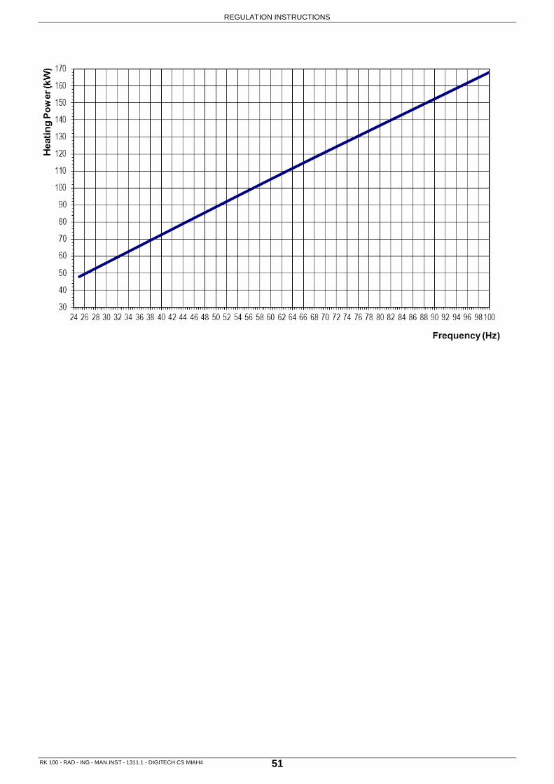
REGULATION INSTRUCTIONS
RK 100 - RAD - ING - MAN.INST - 1311.1 - DIGITECH CS MIAH4 51

REGULATION INSTRUCTIONS
RK 100 - RAD - ING - MAN.INST - 1311.1 - DIGITECH CS MIAH4 52
5.5 Regulating the Gas Valve Offset
When replacing the gas valve, it is necessary to regulate the offset on the new gas valve to guarantee a correct operation of the boiler. N.B. The boiler is only approved for G20 .
5.5.1 Max. power supply regulation - CO2 value
� Switch on the boiler;
� Insert the flue analiser to the inspection point (5) (fig. 1) in order to determine the CO2 value and wait until the boiler operates and the fan runs at the max. speed.
� Check the CO2 value on the instrument and verify that the value is 9.4. If necessary operate on the screw (2) (fig.2) to reduce or increase the CO2 value (ATTENTION, the screw has not a stop point therefore it rotates by completely opening or closing the gas passage).
5.5.2 OFF-SET Regulation
� Make sure that the gas valve (4) (fig. 2) and air intake pipe (6) (fig. 3) pressure points are connected with a silicon pipe (7);
� Slaken the screw (1) and insert a manometer – with a mbar graduate scale;
� Switch on the boiler at the min. capacity (parameter 12);
� The manometer should read a value of -0.07 mbar;
� If it reads a different value, unscrew the cap screw (3) (fig. 2) and operate on the internal plastic screw. By rotating it clockweise or anticlockweise the OFF – SET value can be increased or reduced;
� Once the regulation is completed, screw the cap screw (3) (fig. 2), remove the manometer and screw the pressure point screw (1) (fig. 2);
table n°1
Tipo gas CO 2 %
Natural gas 9,4
Propane LPG 10.3
(5)
(4)
(2)(1)
(3)
Fig. 2
Fig. 1
Fig. 3
6
7

MAINTENANCE INSTRUCTIONS
RK 100 - RAD - ING - MAN.INST - 1311.1 - DIGITECH CS MIAH4 53
6. SERVICING THE APPLIANCE
6.1 General Warnings
All maintenance operations must be carried out by professionally qualified personnel, authorised by Radiant Bruciatori Spa. For servicing within Austra lia refer to contact details on page 2 of this manu al.
The frequency of boiler maintenance must comply wi th current law and, nevertheless, should be carried out once a year.
In order to guarantee the long life of the applian ce and in accordance with the current gas safety regulations, only use original spare parts
Before carrying out any type of maintenance operat ion, disconnect the appliance from the mains electricity supply and close the gas valve.
6.2 Boiler inspection 6.2.1 Main electricity supply Fluctuations in mains voltage (230 V) of about +10 % -15 % do not bring functioning problems. The main electricity production must be in compliance with the CEI relevant and current standards. The boiler must also be equipped of a safety device able to ensure the mains voltage's multipolar disconnection with an opening distance of the contacts of at least 3 mm.
6.2.2 Periodical checks
In order to ensure that the boiler operates efficiently and safely, it is recommended that the appliance is inspected by a suitably competent technician at least once a year. The following operations should be carried out annually:
■ Check the condition of the gas seals and replace where necessary;
■ Check the condition of the water seals and replace where necessary;
■ Visually inspect the condition of the combustion chamber and flame;
■ When required, check that the combustion is correctly regulated and if necessary proceed in line with section “Commissioning the boiler”;
■ Remove and clean any oxidation from the burner;
■ Check that any water leaks and/or oxidation on connections is present;
■ Check that the seal of the room-sealed chamber is undamaged and positioned correctly;
■ Check the primary heat exchanger and clean if necessary;
■ Check the condition and operation of the ignition and gas safety systems. If necessary, remove and clean the scaling from the ignition and flame detection electrodes, paying particular attention to replace them at the correct distance from the burner;
■ Check the heating safety systems: temperature limit safety thermostat, pressure limit safety device;
■ Check the safety valve/s on the heating circuit
■ Check the pre-fill pressure of the expansion vessel (see expansion vessel data plate);
■ Check and if necessary re-set the correct pressure value of the system;
■ Check the correct circulation inside the boiler through filtering devices;
■ Check that the boiler is sloped of 3°/4° toward the back side. Check that the condensate drain system, including outside the boiler (flue system condensate collection devices), allows the condensate to flow freely to the collection devices. If the condensate is discharged to the domestic drainage system, install an inspection trap in the condensate system prior to it entering the drainage system to interrupt the continuity between the two systems;

MAINTENANCE INSTRUCTIONS
RK 100 - RAD - ING - MAN.INST - 1311.1 - DIGITECH CS MIAH4 54
■ Check that the permanent air intake/ventilation points are present, correctly dimensioned and functioning compared with the installed devices and that they are in compliance with current local and national standards.
■ Periodically check the integrity of the flue exhaust system for the safety and the good functioning of the boiler;
■ Check that the connection to the mains electricity supply complies with that reported in the boiler’s instruction manual;
■ Check the electrical connections inside the control panel;
■ Check the condensate trap and that the condensate drain system is working correctly, including any parts of the system outside the boiler such as condensate collection devices along the length of the flue and/or any acid neutralising devices;
■ Check that the condensate flows freely and that there are no exhaust fumes present within the appliance.
6.3 Accessing the boiler
All maintenance operations require one or more of the boiler casing panels to be removed.
The side panels can only be removed after the front panel has been removed.
Front panel:
� Remove the fixing screws at the lower edge of the front panel.
� Grasp the panel � and pull it outwards (fig. 1).
Left and right side panel:
� Remove the fixing screws at the front and lower edge of the side panel to remove.
� Grasp the bottom of the panel, move it sideways and then upwards to remove it �.
To access the electrical connections of the control panel, proceed as follows:
• Remove the front panel (see fig. 1).
• Grasp the left and right
control panel support brackets � and pull them outwards, at the same time rotating the panel downwards.
• Unscrew the four fixing screws � and remove the cover.
Fig. 1
2
4
3
5

MAINTENANCE INSTRUCTIONS
RK 100 - RAD - ING - MAN.INST - 1311.1 - DIGITECH CS MIAH4 55
6.4 Draining the central heating system
If the need arises to drain the system, this can be done as follows:
• Switch the system to “WINTER” mode and ignite the boiler.
• Switch off the power supply to the boiler. • Wait for the boiler to cool down. • Connect a hosepipe to the system drain point and
locate the other end of the hose in a suitable drainage system.
• Open the system drain valve (see fig. 1). • Open the air vents on the radiators, starting with
the highest and moving down the system to the lowest.
• When the system has been drained, close the radiator breather valves and the drain valve.
• If only the boiler needs to be drained, close the flow/return isolating valves on the heating circuit and open the drain valve located at the bottom of the boiler on the pump manifold (see fig. 1);
6.5 Boiler deactivation
When the applicance is no longer required for use, the necessary operation (disconnect the applicance from the main electricity / gas / water supply) must be made by qualified personnel.
Fig. 1
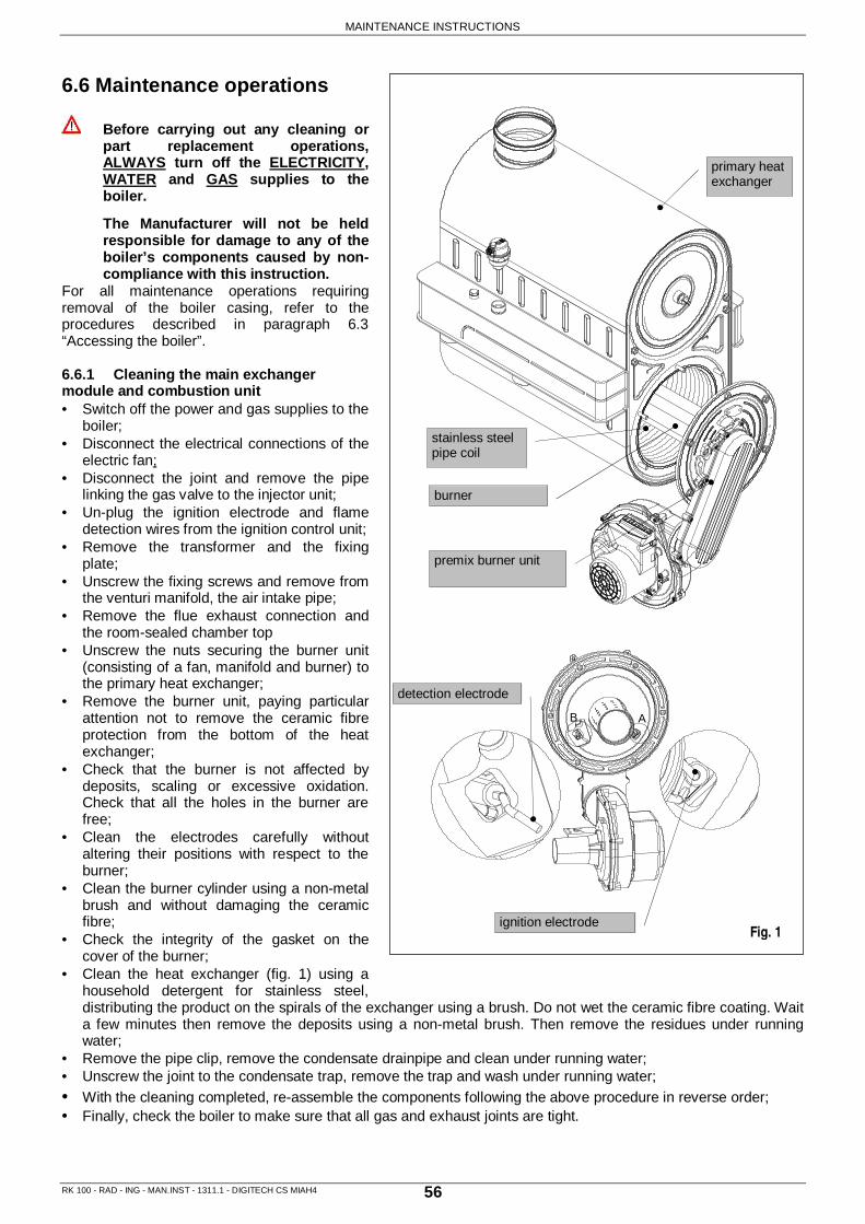
MAINTENANCE INSTRUCTIONS
RK 100 - RAD - ING - MAN.INST - 1311.1 - DIGITECH CS MIAH4 56
6.6 Maintenance operations
Before carrying out any cleaning or part replacement operations, ALWAYS turn off the ELECTRICITY, WATER and GAS supplies to the boiler.
The Manufacturer will not be held responsible for damage to any of the boiler’s components caused by non-compliance with this instruction.
For all maintenance operations requiring removal of the boiler casing, refer to the procedures described in paragraph 6.3 “Accessing the boiler”. 6.6.1 Cleaning the main exchanger module and combustion unit • Switch off the power and gas supplies to the
boiler; • Disconnect the electrical connections of the
electric fan; • Disconnect the joint and remove the pipe
linking the gas valve to the injector unit; • Un-plug the ignition electrode and flame
detection wires from the ignition control unit; • Remove the transformer and the fixing
plate; • Unscrew the fixing screws and remove from
the venturi manifold, the air intake pipe; • Remove the flue exhaust connection and
the room-sealed chamber top • Unscrew the nuts securing the burner unit
(consisting of a fan, manifold and burner) to the primary heat exchanger;
• Remove the burner unit, paying particular attention not to remove the ceramic fibre protection from the bottom of the heat exchanger;
• Check that the burner is not affected by deposits, scaling or excessive oxidation. Check that all the holes in the burner are free;
• Clean the electrodes carefully without altering their positions with respect to the burner;
• Clean the burner cylinder using a non-metal brush and without damaging the ceramic fibre;
• Check the integrity of the gasket on the cover of the burner;
• Clean the heat exchanger (fig. 1) using a household detergent for stainless steel, distributing the product on the spirals of the exchanger using a brush. Do not wet the ceramic fibre coating. Wait a few minutes then remove the deposits using a non-metal brush. Then remove the residues under running water;
• Remove the pipe clip, remove the condensate drainpipe and clean under running water; • Unscrew the joint to the condensate trap, remove the trap and wash under running water; • With the cleaning completed, re-assemble the components following the above procedure in reverse order; • Finally, check the boiler to make sure that all gas and exhaust joints are tight.
B A
Fig. 1
premix burner unit
burner
detection electrode
ignition electrode
primary heat exchanger
stainless steel pipe coil

MAINTENANCE INSTRUCTIONS
RK 100 - RAD - ING - MAN.INST - 1311.1 - DIGITECH CS MIAH4 57
6.6.2 Ignition and/or flame detection electrodes (fig. 1) • Switch off the power supply;
• Un-Plug the electrode wires;
• Slacken the fixing screws;
• Remove the electrodes. When fitting the new ones, check that the seals are not damaged. Replace if necessary;
• Reconnect the wires and re-assemble the components following the above procedure in reverse order;
• Switch on the power supply and restart the appliance;
Check the default positions: make sure that there is a gap of 3±1 mm between detection electrodes, 11±1mm between ignition electrode and burner, 12±1mm between detection electrode and burner, to avoid a boiler malfunction.
IGNITION / FLAME DETECTOR ELECTRODE POSITION
+1-
- 1+
0.5-+3.5
12
11
ignition electrode
detection electrode
transformer
Fig. 1

MAINTENANCE INSTRUCTIONS
RK 100 - RAD - ING - MAN.INST - 1311.1 - DIGITECH CS MIAH4 58
6.6.3 Trasformer (fig. 1) • Switch off the power supply;
• Un-plug the ignition electrode cable and the plug connecting the cable and the printed circuit board;
• Slacken the fixing screws securing the support plate;
• Replace the transformer;
• Reconnect the wires and re-assemble the components following the above procedure in reverse order;
• Switch on the power supply and restart the appliance;
6.6.4 Electric fan (fig. 2) • Switch off the power and gas supplies to
the boiler;
• Remove and dismantle the entire burner unit (see 6.6.1 “Cleaning the main exchanger module and combustion unit”);
• Unscrew the four nuts securing the electric fan to the gas manifold and then remove the electric fan;
• Unscrew the fixing screws from the venturi and remove the electric fan, paying particular attention not to damage the cork gasket;
• Replace the electric fan and re-assemble the components following the above procedure in reverse order;
• Switch on the electricity, water and gas supplies and check the soundness of the joint by measuring the CO2 levels (see “5.5.1 Max power supply regulation- CO2
value”)
electric fan Fig. 2
venturi
burner
premix burner unit
primary heat exchanger
ignition electrode
detection electrode
transformer
Fig. 1

MAINTENANCE INSTRUCTIONS
RK 100 - RAD - ING - MAN.INST - 1311.1 - DIGITECH CS MIAH4 59
6.6.5 Safety thermostat (fig. 1) • Switch off the power supply;
• Un-Plug the connecting wire;
• Unscrew the fixing screws and remove the thermostat;
• Replace the thermostat and re-assemble the components following the above procedure in reverse order;
• Switch on the electricity, water and gas supplies and restart the appliance;
6.6.6 Heating sensor (fig. 1) • Switch off the power supply;
• Close the drain valves and drain the central heating circuit of the boiler;
• Un-Plug the connecting wire;
• Use a 13 mm spanner to remove the heating sensor;
• Replace the sensor and re-assemble the components following the above procedure in reverse order;
• Switch on the electricity, water and gas supplies, open the shut-off valves and fill the central heating circuit. Then restart the appliance, remembering to discharge any air that may be trapped in the system.
6.6.7 Gas valve (fig. 2) • Switch off the power and gas supply to the
boiler;
• Remove and dismantle the entire burner unit (see 6.6.1 “Cleaning the main exchanger module and combustion unit”);
• Unscrew and remove the screws securing the gas valve to the venturi;
• Replace the gas valve and re-assemble the components following the above procedure in reverse order:
• Replace all the gas seals;
• Fully tighten the gas connections;
• Switch on the electricity, water and gas supplies and check for any gas leaks using a soapy solution or leak detector spray;
• Proceed with the Off-set regulation (see “5.5 Regulating the Gas Valve Offset ”)
Fig. 1
heating sensor
safety thermostat
Fig. 2
electronic gas valve
Jets

MAINTENANCE INSTRUCTIONS
RK 100 - RAD - ING - MAN.INST - 1311.1 - DIGITECH CS MIAH4 60
circulation pump
Fig. 1
primary heat exchanger
bracket
bracket
bracket electric fan
premix burner unit
bracket
Fig. 2
6.6.8 Circulating pump (motor body) (fig. 1) • Switch off the power and water supply to the boiler;
• Close the shut-off valves and drain the central heating circuit of the boiler;
• Unscrew the four screws securing the motor body to the impeller body;
• Remove the motor body and check the condition of the washer. If necessary, replace the washer.
• Replace the circulation pump and re-assemble the components following the above procedure in reverse order.
• Switch on the electricity, water and gas supplies and fill the system with water. Check for any leaks from the joints and bleed off any air from the circuit. Restart the boiler.
6.6.9 Primary heat exchanger (fig. 2) Due to the considerable weight of the heat exchanger, pay attention during maintenance operations. � close the shut-off valves and drain the
central heating circuit of the boiler;
• Switch off the power, gas and water supply to the boiler;
• Remove the spring and then the condensate drainpipe;
• Remove the fixing springs and then the delivery and return pipes;
• Remove and dismantle the entire burner unit (see “6.6.1 Cleaning the main exchanger module and combustion unit”);
• Remove the support brackets and pull out the heat exchanger;
• Remove the regulation sensor and the support brackets from the old heat exchanger. Refit them to the new one;
• Replace the heat exchanger and re-assemble the components following the above procedure in reverse order;
• Switch on the electricity, water and gas supplies and fill the system with water. Check for any leaks from the joints and bleed off any air from the circuit. Restart the boiler, making sure that there are no gas leaks;

MAINTENANCE INSTRUCTIONS
RK 100 - RAD - ING - MAN.INST - 1311.1 - DIGITECH CS MIAH4 61
6.6.10 Modulation circuit board (see fig. 1-2)
• Open the control panel (see 6.3 “Accessing the boiler”);�
• Disconnect all the connectors, remove the regulating knobs, unscrew the four fixing screws and remove the modulation circuit board;
• Replace the circuit board and re-assemble the components following the above procedure in reverse order;
• Switch on the electricity, water and gas supplies and regulate the boiler (see 5.4 “Gas data”);
The present parameters of the printed circuit board correspond to a 100 kw only heating condensing boiler fed by natural gas.
When replacing the modulation circuit board, it’s necessary to set parameter according to the boiler model (see 5.3” Setting the parameters’).
modulation circuit board
modulation circuit board
Fig. 1
Fig. 2

MAINTENANCE INSTRUCTIONS
RK 100 - RAD - ING - MAN.INST - 1311.1 - DIGITECH CS MIAH4 62
VG
TSF
+24V
GNDPWM
HS
Pacq
MP
Se
Se
Ta
Ta
NL
nenecema
ma
cearar
SR
TF
TS
ERm
ace
Tra
EA
ma
ce
ma
ce
C
EV
grbi
gima
cema
ce
ma
ce
ma
27262829303132333435363738394041424344
58596061
57
43
21
M16
M15
M10
M8M4
M2
M5M7M9M12
1716
1514
1312
7 8 9 10 11
SE
TA
6.8 Wiring diagrams 6.7.1 Only heating version - R
Key ER: Ionisation electrode EA: Ignition electrode C: Circulating pump VG: Gas valve TRA: Ignition transformer TF: Thermo fuse (102 °C) TS: Safety thermostat
Pacq: Water pressure switch SR: Heating sensor EV: Fan MP: Terminal board SE: Outdoor temperature sensor TA: Open Therm Remote control -
Room thermostat TFS: Safety thermo fuse 318°C
L: Line N: Neutral ne: Black ce: Blue ma: Brown ar: Orange gi: Yellow bi: White gr: Grey

MAINTENANCE INSTRUCTIONS
RK 100 - RAD - ING - MAN.INST - 1311.1 - DIGITECH CS MIAH4 63
SS
ne ne
VG
TSF
+24V
GNDPWM
HS
Pacq
MP
Se
Se
TaT
aN
L
nenecema
ma
cearar
SR
TF
TS
ERm
ace
Tra
EA
ma
ce
ma
ce
C
EV
grbi
gima
cema
ce
ma
ce
ma
27262829303132333435363738394041424344
58596061
57
43
21
M16
M15
M10
M8M4
M2
M5M7M9M12
1716
1514
1312
7 8 9 10 11
ma
ce ne ma
VD
ce
SE
TA
6.7.2 Only heating + storage cylinder installation version - RS
See olso “3.8.5 3-way valve kit fitted for D.H.W. storage cylinder connection”
Remote storage cylinder connection
• M9 terminal block DHW cylinder sensor: insert the sensor cable inside the control panel inserting terminals 34 and 35. It is not necessary to follow a sequence with the wires.
• M4 terminal block – 3-way valve: connect the 3-way valve motor cable through the Molex terminal. Insert the cable inside the control panel and connect cable terminals to M4 terminal block respecting the following coupling: light-blue – terminal no.9; brown – terminal no.8; black – terminal no.10
Key ER: Ionisation electrode EA: Ignition electrode C: Circulating pump VD: Diverter valve VG: Gas valve TRA: Ignition transformer TF: Thermo fuse (102 °C) TS: Safety thermostat
Pacq: Water pressure switch SR: Heating sensor SS: D.H.W. sensor (remote storage
cylinder) EV: Fan MP: Terminal board SE: Outdoor temperature sensor TA: Open Therm Remote control -
Room thermostat TFS: Safety thermo fuse 318°C
L: Line N: Neutral ne: Black ce: Blue ma: Brown ar: Orange gi: Yellow bi: White gr: Grey

MAINTENANCE INSTRUCTIONS
RK 100 - RAD - ING - MAN.INST - 1311.1 - DIGITECH CS MIAH4 64
6.8 Troubleshooting
To display the last 5 errors, keep pressed the ‘ ’ INFO button, in OFF mode position, for 5 seconds. The errors number will appear in chronological order (-1- = first fault… -5- = last fault). Use ‘ ’ and ‘ ’ buttons
of Heating Temperature setting, to scroll the list of saved errors. To reset the errors list press the‘ ’ RESET button. Press the ‘ ’ INFO button to exit the errors display mode.
ERROR CODE PROBLEM POSSIBLE CAUSE REMEDY RESET
E01
IONISATION PROBLEM
WITHOUT FLAME IGNITION a. NO GAS. b. IGNITION ELECTRODE
BROKEN OR EARTHED. c. GAS VALVE
MALFUNCTION. d. IGNITION SEQUENCE
SET TOO LOW. WITH FLAME IGNITION e. POWER SUPPLY LINE
AND NEUTRAL CABLES REVERSED.
f. IONISATION ELECTRODE MALFUNCTION.
g. IONISATION ELECTRODE CABLE DISCONNECTED.
a. CHECK MAINS GAS SUPPLY.
b. REPLACE PART. c. REPLACE PART. d. SET THE IGNITION
SEQUENCE. e. CONNECT THE
BOILER PROPERLY. f. REPLACE PART. g. CONNECT THE
IONISATION ELECTRODE CABLE.
Manual Reset (press the ‘ ’ Reset button)
E02 SAFETY THERMOSTAT TRIPPED (95°C)
h. THERMOSTAT MALFUNCTION OR OUT OF CALIBRATION.
i. THERMOSTAT CABLE DISCONNECTED.
i. REPLACE PART. j. CHECK THE WIRING.
Manual Reset (press the ‘ ’ Reset button)
E03 102° C THERMO FUSE TRIPPED
k. THERMO FUSE BROKEN. l. THERMO FUSE CABLE
OR POWER SUPPLY DISCONNECTED.
k. REPLACE PART; l. CHECK THE WIRING
AND THE POWER SUPPLY CONNECTION.
Manual Reset (press the ‘ ’
Reset button)
E04 NO WATER IN THE SYSTEM
m. INSUFFICIENT WATER PRESSURE IN THE SYSTEM (STOPS AT 0.3 BAR).
n. WATER PRESSURE SWITCH CABLE DISCONNECTED.
o. WATER PRESSURE SWITCH MALFUNCTION.
m. FILL THE SYSTEM. n. CHECK THE WIRING.
o. REPLACE PART.
Automatic
E05 HEATING SENSOR
p. SENSOR MALFUNCTION OR OUT OF CALIBRATION (RESISTANCE VALUE 10 kOhms AT 25 °C).
q. SENSOR CABLE DISCONNECTED OR WET.
p. REPLACE PART. q. CHECK THE POWER
SUPPLY CONNECTION.
Automatic

MAINTENANCE INSTRUCTIONS
RK 100 - RAD - ING - MAN.INST - 1311.1 - DIGITECH CS MIAH4 65
ERROR CODE PROBLEM POSSIBLE CAUSE REMEDY RESET
E06
D.H.W SENSOR / CYLINDER (RS version only - with connection to a remote storage cylinder)
r. SENSOR MALFUNCTION OR OUT OF CALIBRATION (RESISTANCE VALUE 10 kOhms AT 25 °C).
s. SENSOR CABLE DISCONNECTED OR WET.
r. REPLACE PART. s. CHECK THE POWER
SUPPLY CONNECTION.
Automatic
E15 RETURN SENSOR
t. SENSOR MALFUNCTION OR OUT OF CALIBRATION (RESISTANCE VALUE 10 kOhms AT 25 °C).
u. SENSOR CABLE DISCONNECTED OR WET.
t. REPLACE PART. u. CHECK THE POWER
SUPPLY CONNECTION.
Automatic
E16 FAN
v. BURNT w. POWER SUPPLY
CABLE MALFUNCTION
v. REPLACE PART. w. REPLACE PART.
Automatic
E18 INADEQUATE CIRCULATION
x. PRIMARY OR SECONDARY HEAT EXCHANGER OBSTRUCTED.
y. PUMP MALFUNCTION OR PUMP IMPELLER DIRTY.
x. CLEAN OR REPLACE PART.
y. CLEAN OR REPLACE PART.
Automatic
E21 GENERAL PCB MALFUNCTION
z. MICROPROCESSOR MALFUNCTION: IT DETECTS A WRONG SIGNAL .
z. THE PCB RESETS AUTOMATICALLY THE ERROR.
Automatic
E22 PARAMETER PROGRAMMING REQUEST
aa. LOSS OF MICROPROCESSOR MEMORY.
aa. REPROGRAM PARAMETERS.
Manual Reset (Switch off the power supply)
E35 FLAME DETECTION MALFUNCTION
bb. IONISATION ELECTRODE MALFUNCTION
cc. IONISATION ELECTRODE CABLE MALFUNCTION
dd. PRINTED CIRCUIT BOARD MALFUNCTION
bb. REPLACE OR CLEAN PART
cc. REPLACE PART dd. REPLACE PART
Manual Reset (press the ‘ ’ Reset button)
E40 ELECTRIC POWER SUPPLY
ee. ELECTRIC POWER SUPPLY OUT OF THE OPERATION RANGE
ee. CHECK THE POWER SUPPLY NETWORK (THE ERROR DISAPPEARS AUTOMATICALLY WHEN THE POWER SUPPLY IS BACK WITHIN THE REQUIRED RANGE)
Automatic

MAINTENANCE INSTRUCTIONS
RK 100 - RAD - ING - MAN.INST - 1311.1 - DIGITECH CS MIAH4 66
6.9 Function codes 6.9.1 Function codes
Code Function Description
F07 Flue test function active (Chimney-Sweeper)
Pressing ‘ ’ button for 7 seconds the Flue test function is enabled. Pressing the boiler Off button the function is disabled. The Flue test function operates the boiler at the maximum heating pressure for 15 minutes without any modulation. The function is useful for combustion testing.
F08
Frost Protection function (Central heating circuit)
The function is automatically enabled when the heating sensor detects a temperature of 5 °C. The boiler operates at minimum gas pressure with the diverter valve in the ‘winter’ position. The function is disabled when the temperature detected by the sensor reaches 30°C.
F09
Frost Protection function (D.H.W circuit) (RS version only - with connection to a remote storage cylinder)
The function is automatically enabled when the D.H.W sensor detects a temperature of 4 °C. The boiler operates at minimum gas pressure with the diverter valve in the ‘summer’ position. The function is disabled when the temperature detected by the sensor is 8 °C in the D.H.W circuit or 3 0 °C in the central heating circuit.
F28 Legionella Prevention Function
Function active for storage boilers only. It comes into operation every 7 days. It brings the hot water temperature of the storage cylinder up to 60°C whatever temperature value is set for hot water.
F33 System purging function
The function is automatically enabled at the first ignition of the boiler. The boiler operates a series of cycles for a period of 5 minutes. Each cycle consists in: the pump is enabled for 40 seconds and then disabled for 20 seconds. The starting of the boiler is only allowed at the end of this function. In case of an open contact of the water pressure switch, this function can be enabled during the normal boiler operation. Once the contact is closed a purging cycle of 2 minutes is performed.

MAINTENANCE INSTRUCTIONS
RK 100 - RAD - ING - MAN.INST - 1311.1 - DIGITECH CS MIAH4 67
6.10 Parts list 6.10.1 Main components
code description
25-00055 PUMP UPS 25-80 130
25-00064 WASHER EDPM 1" 1/4
25-00065 CONDENSATE TRAP
25-00066 CONDENSATE DRAIN PIPE
30-00003 CONDENSING EXCHANGER DUO 100 KW
30-00008 GAS VALVE w/CABLE
30-00009 VENTURI MANIFOLD
35031LA IGNITION ELECTRODE ISO
35032LA FLAME IONISATION ELECTRODE ISO
37035LA EXHAUST FAN NRG137
40-00020 DIAPHRAGM Ø 11
40-00077 PRINTED CIRCUIT BOARD DIGITECH CS MIAH400
43001LA WASHER Ø 23.5x17x2 3/4"
43055LA 1/2" O-RING WASHER
43235LA WASHER 1" 1/2 5x35x2 AFM34 o 44x35x2 AFM34
47024LA ON/OFF SWITCH L5 16A/250V
50-00013 VENTURI - AIR INTAKE PIPE CONNECTION
55-00016 O-RING 4275 EXHAUST FAN/VENTURI MANIFOLD
59015LA WATER PRESSURE SWITCH
73507LA D.H.W. - HEATING 1/8" WHITE SENSOR
73517LP THERMO FUSE 102°C RED ISOTHERM.
86006LA SAFETY THERMOSTAT 95C°
88023LA TRANSFORMER AC1 230V AC 60 HZ
96005LA 3 BAR RELIEF VALVE ½”
96012LA AUTOMATIC AIR VENT VALVE 3/8”

MAINTENANCE INSTRUCTIONS
RK 100 - RAD - ING - MAN.INST - 1311.1 - DIGITECH CS MIAH4 68

RADIANT BRUCIATORI s.p.a. Via Pantanelli, 164/166 - 61025 Montelabbate (PU) Tel. +39 0721 9079.1 • fax. +39 0721 9079279 e-mail: info@radiant • Internet: http://www.radiant.it
THE TECHNICAL DATA AND MEASUREMENTS ARE PROVIDED FOR INFORMATION PURPOSES ONLY AND ARE NOT BINDING. THE COMPANY RESERVES THE RIGHT TO APPLY VARIATIONS WITHOUT PRIOR NOTIFICATION. NEITHER WILL THE COMPANY BE HELD RESPONSIBLE FOR ANY INACCURACIES IN THIS HANDBOOK DERIVING FROM PRINTING OR TRANSLATION ERRORS. E+OEALL RIGHTS RESERVED. NO PART OF THIS DOCUMENT MAY BE REPRODUCED, MEMORISED IN ANY FILING SYSTEMS OR TRANSMITTED IN ANY FORM WHATSOEVER, INCLUDING ELECTRONIC, MECHANICAL, PHOTOCOPIES, RECORDINGS OR ANY OTHER MEANS WITHOUT THE COMPANY’S PRIOR WRITTEN APPROVAL.