agilent technologies 8960 series 10 e5515b,c,t wireless...
TRANSCRIPT

Agilent Technologies 8960 Series 10 E5515B,C,T Wireless Communications Test Set
Manual Operation: Getting Started Guide
AMPS/136 Mobile Test Application E1961A Revision: A.04 cdma2000/IS-2000 Mobile Test Application E1962A Revision A.01, E1962B Revision: B.01
GPRS Mobile Test Application E1964A Revision: A.01GSM Mobile Test Application E1960A Revision: A.07
GSM_AMPS/136 Fast Switch Mobile Test Application E1985A Revision: A.01
Agilent Part No: 5967-5124
Print Date: March 2001
© Copyright Agilent Technologies 2001All Rights Reserved
��
http://www.agilent.com/find/8960support

Edition/Print DateAll Editions and Updates of this manual and their creation dates are listed below.
March 2001 - 5967-5124
Safety SummaryThe following general safety precautions must be observed during all phases of operation of this instrument. Failure to comply with these precautions or with specific warnings elsewhere in this manual violates safety standards of design, manufacture, and intended use of the instrument. Agilent Technologies Inc. assumes no liability for the customer’s failure to comply with these requirements.
GENERAL
This product is a Safety Class 1 instrument (provided with a protective earth terminal). The protective features of this product may be impaired if it is used in a manner not specified in the operation instructions.
All Light Emitting Diodes (LEDs) used in this product are Class 1 LEDs as per IEC 60825-1.
This product has been designed and tested in accordance with IEC Publication 1010, "Safety Requirements for Electronic Measuring Apparatus," and has been supplied in a safe condition. This instruction documentation contains information and warnings which must be followed by the user to ensure safe operation and to maintain the product in a safe condition.
2

ENVIRONMENTAL CONDITIONS
This instrument is intended for indoor use in an installation category II, pollution degree 2 environment. It is designed to operate at a maximum relative humidity of 95% and at altitudes of up to 2000 meters. Refer to the specifications tables for the ac mains voltage requirements and ambient operating temperature range.
Ventilation Requirements: When installing the product in a cabinet, the convection into and out of the product must not be restricted. The ambient temperature (outside the cabinet) must be less than the maximum operating temperature of the product by 4° C for every 100 watts dissipated in the cabinet. If the total power dissipated in the cabinet is greater than 800 watts, then forced convection must be used.
BEFORE APPLYING POWER
Verify that the product is set to match the available line voltage, the correct fuse is installed, and all safety precautions are taken. Note the instrument's external markings described under Safety Symbols.
GROUND THE INSTRUMENT
To minimize shock hazard, the instrument chassis and cover must be connected to an electrical protective earth ground. The instrument must be connected to the ac power mains through a grounded power cable, with the ground wire firmly connected to an electrical ground (safety ground) at the power outlet. Any interruption of the protective (grounding) conductor or disconnection of the protective earth terminal will cause a potential shock hazard that could result in personal injury.
FUSES
Only fuses with the required rated current, voltage, and specified type (normal blow, time delay, etc.) should be used. Do not use repaired fuses or short-circuited fuse holders. To do so could cause a shock or fire hazard.
DO NOT OPERATE IN AN EXPLOSIVE ATMOSPHERE
Do not operate the instrument in the presence of flammable gases or fumes.
DO NOT REMOVE THE INSTRUMENT COVER
Operating personnel must not remove instrument covers. Component replacement and internal adjustments must be made only by qualified service personnel.
Instruments that appear damaged or defective should be made inoperative and secured against unintended operation until they can be repaired by qualified service personnel.
3

WARNING The WARNING sign denotes a hazard. It calls attention to a procedure, practice, or the like, which, if not correctly performed or adhered to, could result in personal injury. Do not proceed beyond a WARNING sign until the indicated conditions are fully understood and met.
CAUTION The CAUTION sign denotes a hazard. It calls attention to an operating procedure, or the like, which, if not correctly performed or adhered to, could result in damage to or destruction of part or all of the product. Do not proceed beyond a CAUTION sign until the indicated conditions are fully understood and met.
Safety Symbols
Caution, refer to accompanying documents
Warning, risk of electric shock
Earth (ground) terminal
Alternating current
Frame or chassis terminal
Standby (supply). Units with this symbol are not completely disconnected from ac mains when this switch is off.
To completely disconnect the unit from ac mains, either disconnect the power cord, or have a qualified electrician install an external switch.
4

Product MarkingsCE - the CE mark is a registered trademark of the European Community. A CE mark accompanied by a year indicated the year the design was proven.
CSA - the CSA mark is a registered trademark of the Canadian Standards Association.
CERTIFICATIONAgilent Technologies certifies that this product met its published specifications at the time of shipment from the factory. Agilent Technologies further certifies that its calibration measurements are traceable to the United States National Institute of Standards and Technology, to the extent allowed by the Institute’s calibration facility, and to the calibration facilities of other International Standards Organization members
5

Agilent Technologies Warranty Statement for Commercial Products Agilent Technologies 8960 Series 10 E5515B,C,T Wireless Communications Test Set,AMPS/136 Mobile Test Application E1961Acdma2000 Mobile Test Application E1962BGPRS Mobile Test Application E1964AGSM Mobile Test Application E1960AIS-2000 Mobile Test Application E1962A
Duration of Warranty: 1 year
1. Agilent Technologies warrants Agilent Technologies hardware, accessories and supplies against defects in materials and workmanship for the period specified above. If Agilent Technologies receives notice of such defects during the warranty period, Agilent Technologies will, at its option, either repair or replace products which prove to be defective. Replacement products may be either new or like-new.
2. Agilent Technologies warrants that Agilent Technologies software will not fail to execute its programming instructions, for the period specified above, due to defects in material and workmanship when properly installed and used. If Agilent Technologies receives notice of such defects during the warranty period, Agilent Technologies will replace software media which does not execute its programming instructions due to such defects.
3. Agilent Technologies does not warrant that the operation of Agilent Technologies products will be uninterrupted or error free. If Agilent Technologies is unable, within a reasonable time, to repair or replace any product to a condition as warranted, customer will be entitled to a refund of the purchase price upon prompt return of the product.
4. Agilent Technologies products may contain remanufactured parts equivalent to new in performance or may have been subject to incidental use.
5. The warranty period begins on the date of delivery or on the date of installation if installed by Agilent Technologies. If customer schedules or delays Agilent Technologies installation more than 30 days after delivery, warranty begins on the 31st day from delivery.
6

6. Warranty does not apply to defects resulting from (a) improper or inadequate maintenance or calibration, (b) software, interfacing, parts or supplies not supplied by Agilent Technologies, (c) unauthorized modification or misuse, (d) operation outside of the published environmental specifications for the product, or (e) improper site preparation or maintenance.
7. TO THE EXTENT ALLOWED BY LOCAL LAW, THE ABOVE WARRANTIES ARE EXCLUSIVE AND NO OTHER WARRANTY OR CONDITION, WHETHER WRITTEN OR ORAL IS EXPRESSED OR IMPLIED AND AGILENT TECHNOLOGIES SPECIFICALLY DISCLAIMS ANY IMPLIED WARRANTIES OR CONDITIONS OR MERCHANTABILITY, SATISFACTORY QUALITY, AND FITNESS FOR A PARTICULAR PURPOSE.
8. Agilent Technologies will be liable for damage to tangible property per incident up to the greater of $300,000 or the actual amount paid for the product that is the subject of the claim, and for damages for bodily injury or death, to the extent that all such damages are determined by a court of competent jurisdiction to have been directly caused by a defective Agilent Technologies product.
9. TO THE EXTENT ALLOWED BY LOCAL LAW, THE REMEDIES IN THIS WARRANTY STATEMENT ARE CUSTOMER’S SOLE AND EXCLUSIVE REMEDIES. EXCEPT AS INDICATED ABOVE, IN NO EVENT WILL AGILENT TECHNOLOGIES OR ITS SUPPLIERS BE LIABLE FOR LOSS OF DATA OR FOR DIRECT, SPECIAL, INCIDENTAL, CONSEQUENTIAL (INCLUDING LOST PROFIT OR DATA), OR OTHER DAMAGE, WHETHER BASED IN CONTRACT, TORT, OR OTHERWISE.
FOR CONSUMER TRANSACTIONS IN AUSTRALIA AND NEW ZEALAND: THE WARRANTY TERMS CONTAINED IN THIS STATEMENT, EXCEPT TO THE EXTENT LAWFULLY PERMITTED, DO NOT EXCLUDE RESTRICT OR MODIFY AND ARE IN ADDITION TO THE MANDATORY STATUTORY RIGHTS APPLICABLE TO THE SALE OF THIS PRODUCT TO YOU.
ASSISTANCEProduct maintenance agreements and other customer assistance agreements are available for Agilent Technologies products. For any assistance, contact your nearest Agilent Technologies Sales and Service Office.
7

Service and SupportAny adjustment, maintenance, or repair of this product must be performed by qualified personnel. Contact your customer engineer through your local Agilent Technologies Service Center. You can find a list of local service representatives on the Web at:
http://www.agilent-tech.com/services/English/index.html
If you do not have access to the Internet, one of these centers can direct you to your nearest representative:
United States Test and Measurement Call Center(Toll free in US)
(800) 452-4844
Europe
(31 20) 547 9900
Canada
(905) 206-4725
Japan Measurement Assistance Center
(81) 426 56 7832(81) 426 56 7840 (FAX)
Latin America
(305) 267 4288 (FAX)
Australia/New Zealand
1 800 629 485 (Australia)0800 738 378 (New Zealand)
Asia-Pacific
(852) 2599 7777(852) 2506 9285 (FAX)
8
Regional Sales OfficesUnited States of America:Agilent Technologies (tel) 1 800 452 4844Test and Measurement Call Center P.O. Box 4026Englewood, CO 80155-4026
Canada:Agilent Technologies Canada Inc. (tel) 1 877 894 44142660 Matheson Blvd. EMississauga, OntarioL4W 5G1
Europe:Agilent Technologies (tel) (3120) 547 9999European Marketing OrganizationP.O. Box 9991180 AZ AmstelveenThe Netherlands
Japan:Agilent Technologies Japan Ltd. (tel) (81) 456-56-7832Measurement Assistance Center (fax) (81) 426-56-78409-1 Takakura-Cho, Hachioji-Shi,Tokyo 192-8510, Japan
Latin America:Agilent Technologies (tel) (305) 267 4245Latin America Region Headquarters (fax) (305) 267 42865200 Blue Lagoon Drive, Suite #950Miami, Florida 33126U.S. A.
9

Australia/New Zealand:Agilent Technologies Australia Pty Ltd. Australia New Zealand347 Burwood Highway (tel) 1 800 629 485 (tel) 0 800 738 378Forest Hill, Victoria 3131 (fax) (61 3) 9272 0749 (fax) (64 4) 802 6881
Asia Pacific:Agilent Technologies (tel) (852) 3197 777724/F, Cityplaza One, (fax) (852) 2506 9233111 Kings Road,Taikoo Shing, Hong Kong
10

Table 1Declaration of Conformity According to ISO/IEC Guide 22 and CEN/CENELEC EN 45014
For further information, please contact your local Agilent Technologies sales office, agent or distributor. Authorized EU-representative: Agilent Technologies Deutschland, GmbH, Herrenberger Strabe 130, D 71034 Boblingen, Germany
Manufacturer’s Name Agilent Technologies UK Limited Agilent Technologies, Incorporated
Manufacturer’s Address Electronics Products & SolutionsGroup - QueensferrySouth QueensferryWest Lothian, EH30 9TGScotland, United Kingdom
RF Communications PGU24001 E. Mission AvenueLiberty Lake, Washington99019-9599USA
Declares, that the productProduct Name:
Model Number:Product Options:
8960 Series 10 Wireless Communications Test SetE5515BThis declaration covers all options of the above product.
Conforms with the following European Directives
The product herewith complies with the requirements of the Low Voltage Directive 73/23/EEC and the EMC Directive 89/336/EEC (including 93/68/EEC) and carries the CD Marking accordingly.
Conforms with the following product standards:
EMC
Standard
IEC 61326-1:1997+A1:1998/EN 61326-1:1997+A1:1998 CISPR 11:1990 / EN 55011:1991 IEC 61000-4-2:1995+A1:1998 / EN 61000-4-2:1995IEC 61000-4-3:1995 / EN 61000-4-3:1995IEC 61000-4-4:1995 / EN 61000-4-4:1995IEC 61000-4-5:1995 / EN 61000-4-5:1995IEC 61000-4-6:1996 / EN 61000-4-6:1996IEC 61000-4-11:1994 / EN 61000-4-11:1994
Limit
Group 1 Class A [1]
4kV CD, 8kV AD
3 V/m, 80-1000 MHz0.5V signal lines, 1kV power lines0.5 kV line-line, 1 kV line-ground3V, 0.15-80 MHz1 cycle, 100%
Safety IEC 61010-1:1990+A1:1992+A2:1995 / EN 61010-1:1993+A2:1995Canada CSA C22.2 No. 1010.1:1992
Supplemental Information:[1] The product was tested in a typical configuration with Agilent Technologies test systems
14 December 2000R.M. Evans / Quality Manager
14 December 2000W. V. Roland / Reliability & Regulatory Engineering Manager
11

Declaration of ConformityAccording to ISO/IEC Guide 22 and CEN/CENELEC EN 45014
For further information, please contact your local Agilent Technologies sales office, agent or distributor. Authorized EU-representative: Agilent Technologies Deutschland, GmbH, Herrenberger Strabe 130, D 71034 Boblingen, Germany
Manufacturer’s Name Agilent Technologies, Incorporated Agilent Technologies, Incorporated
Manufacturer’s Address Electronics Products & SolutionsGroup - QueensferrySouth QueensferryWest Lothian, EH30 9TGScotland, United Kingdom
Declares, that the productProduct Name:
Model Number:Product Options:
8960 Series 10 Wireless Communications Test SetE5515TThis declaration covers all options of the above product.
Conforms with the following European Directives
The product herewith complies with the requirements of the Low Voltage Directive 73/23/EEC and the EMC Directive 89/336/EEC (including 93/68/EEC) and carries the CD Marking accordingly.
Conforms with the following product standards:
EMC
Standard
IEC 61326-1:1997+A1:1998 / EN 61326-1:1997+A1:1998 CISPR 11:1990 / EN 55011:1991 IEC 61000-4-2:1995+A1:1998 / EN 61000-4-2:1995IEC 61000-4-3:1995 / EN 61000-4-3:1995IEC 61000-4-4:1995 / EN 61000-4-4:1995IEC 61000-4-5:1995 / EN 61000-4-5:1995IEC 61000-4-6:1996 / EN 61000-4-6:1996IEC 61000-4-11:1994 / EN 61000-4-11:1994
Limit
Group 1 Class A [1]
4kV CD, 8kV AD
3 V/m, 80-1000 MHz0.5V signal lines, 1kV power lines0.5 kV line-line, 1 kV line-ground3V, 0.15-80 MHz1 cycle, 100%
Safety IEC 61010-1:1990+A1:1992+A2:1995 / EN 61010-1:1993+A2:1995Canada CSA C22.2 No. 1010.1:1992
Supplemental Information:[1] The product was tested in a typical configuration with Agilent Technologies test systems
14 December 2000W. V. Roland / Reliability & Regulatory Engineering Manager
12

13
Manufacturer’s DeclarationThis statement is provided to comply with the requirements of the German Sound Emission Directive, from 18 January 1991.
This product has a sound pressure emission (at the operator position) < 70 dB(A).
• Sound Pressure Lp < 70 dB(A).
• At Operator Position.
• Normal Operation.
• According to ISO 7779:1988/EN 27779:1991 (Type Test).
HerstellerbescheinigungDiese Information steht im Zusammenhang mit den Anforderungen der Maschinenlärminformationsverordnung vom 18 Januar 1991.
• Schalldruckpegel Lp < 70 dB(A).
• Am Arbeitsplatz.
• Normaler Betrieb.
• Nach ISO 7779:1988/EN 27779:1991 (Typprüfung).

14

Contents
1. AMPS/136 Mobile Test Application . . . . . . . . . . . . . . . . . . . . . . .19
How Do I Make Measurements on a Mobile? . . . . . . . . . . . . . . . . . . . . . . . . . . . . . . . 20A. Establish a call. . . . . . . . . . . . . . . . . . . . . . . . . . . . . . . . . . . . . . . . . . . . . . . . . . . 20 B. Select measurements. . . . . . . . . . . . . . . . . . . . . . . . . . . . . . . . . . . . . . . . . . . . . . 21
How Do I Change Measurement Setup? . . . . . . . . . . . . . . . . . . . . . . . . . . . . . . . . . . . 22A. Select a measurement. . . . . . . . . . . . . . . . . . . . . . . . . . . . . . . . . . . . . . . . . . . . . . 22B. Set up the measurement. . . . . . . . . . . . . . . . . . . . . . . . . . . . . . . . . . . . . . . . . . . . 23
How Do I Turn Off a Measurement? . . . . . . . . . . . . . . . . . . . . . . . . . . . . . . . . . . . . . . 24How Do I Change Call Parameters? . . . . . . . . . . . . . . . . . . . . . . . . . . . . . . . . . . . . . . 25How do I change the MS TX Level? . . . . . . . . . . . . . . . . . . . . . . . . . . . . . . . . . . . . . . 26
A. Change the digital MS TX level immediately. . . . . . . . . . . . . . . . . . . . . . . . . . . 26B. Change the MS TX level during a handoff. . . . . . . . . . . . . . . . . . . . . . . . . . . . . 27
How do I Perform a Handoff? . . . . . . . . . . . . . . . . . . . . . . . . . . . . . . . . . . . . . . . . . . . 28How Do I Configure the Test Set for My Test System? . . . . . . . . . . . . . . . . . . . . . . . 29
A. Configure instrument information and setup. . . . . . . . . . . . . . . . . . . . . . . . . . . . 29B. Set amplitude offsets. . . . . . . . . . . . . . . . . . . . . . . . . . . . . . . . . . . . . . . . . . . . . . 30C. Check the message log. . . . . . . . . . . . . . . . . . . . . . . . . . . . . . . . . . . . . . . . . . . . . 31
How Do I End a Call? . . . . . . . . . . . . . . . . . . . . . . . . . . . . . . . . . . . . . . . . . . . . . . . . . 32
2. cdma2000/IS-2000 Mobile Test Application . . . . . . . . . . . . . . . .33
How Do I Make Measurements on a Mobile? . . . . . . . . . . . . . . . . . . . . . . . . . . . . . . . 34A. Establish a call. . . . . . . . . . . . . . . . . . . . . . . . . . . . . . . . . . . . . . . . . . . . . . . . . . . 34B. Select measurements. . . . . . . . . . . . . . . . . . . . . . . . . . . . . . . . . . . . . . . . . . . . . . 35
How Do I View a Graphical Measurement? . . . . . . . . . . . . . . . . . . . . . . . . . . . . . . . . 36How Do I Change the Measurement Setup? . . . . . . . . . . . . . . . . . . . . . . . . . . . . . . . . 37
A. Select a measurement. . . . . . . . . . . . . . . . . . . . . . . . . . . . . . . . . . . . . . . . . . . . . . 37B. Set up the measurement. . . . . . . . . . . . . . . . . . . . . . . . . . . . . . . . . . . . . . . . . . . . 38
How Do I Turn Off a Measurement? . . . . . . . . . . . . . . . . . . . . . . . . . . . . . . . . . . . . . . 39How Do I Set Up a Call? . . . . . . . . . . . . . . . . . . . . . . . . . . . . . . . . . . . . . . . . . . . . . . . 40How Do I Change Call Parameters? . . . . . . . . . . . . . . . . . . . . . . . . . . . . . . . . . . . . . . 42
15

Contents
How Do I Change Cell Information? . . . . . . . . . . . . . . . . . . . . . . . . . . . . . . . . . . . . . . 43A. Set cell parameters. . . . . . . . . . . . . . . . . . . . . . . . . . . . . . . . . . . . . . . . . . . . . . . . 43
1. Select the Cell Parameters menu.. . . . . . . . . . . . . . . . . . . . . . . . . 432. Set a cell parameter. . . . . . . . . . . . . . . . . . . . . . . . . . . . . . . . . . . . 44
B. Set access parameters. . . . . . . . . . . . . . . . . . . . . . . . . . . . . . . . . . . . . . . . . . . . . . 451. Select the Access Parameters menu. . . . . . . . . . . . . . . . . . . . . . . 452. Set an access parameter. . . . . . . . . . . . . . . . . . . . . . . . . . . . . . . . . 46
C. Set registration parameters. . . . . . . . . . . . . . . . . . . . . . . . . . . . . . . . . . . . . . . . . . 471. Select the Registration Parameters menu.. . . . . . . . . . . . . . . . . . 472. Set a registration parameter. . . . . . . . . . . . . . . . . . . . . . . . . . . . . 48
How Do I Change Code Channel Levels? . . . . . . . . . . . . . . . . . . . . . . . . . . . . . . . . . . 49How Do I Perform a Handoff? . . . . . . . . . . . . . . . . . . . . . . . . . . . . . . . . . . . . . . . . . . . 50How Do I Configure the Test Set for My Test System? . . . . . . . . . . . . . . . . . . . . . . . 51
A. Configure instrument information and setup. . . . . . . . . . . . . . . . . . . . . . . . . . . . 51B. Set amplitude offsets. . . . . . . . . . . . . . . . . . . . . . . . . . . . . . . . . . . . . . . . . . . . . . 52C. Check message log. . . . . . . . . . . . . . . . . . . . . . . . . . . . . . . . . . . . . . . . . . . . . . . . 53
How Do I End a Call? . . . . . . . . . . . . . . . . . . . . . . . . . . . . . . . . . . . . . . . . . . . . . . . . . 54
3. GPRS Mobile Test Application . . . . . . . . . . . . . . . . . . . . . . . . . 55
How Do I Make Measurements on a Mobile? . . . . . . . . . . . . . . . . . . . . . . . . . . . . . . . 56A. Establish a data connection. . . . . . . . . . . . . . . . . . . . . . . . . . . . . . . . . . . . . . . . . 56B. Select measurements. . . . . . . . . . . . . . . . . . . . . . . . . . . . . . . . . . . . . . . . . . . . . . 57
How Do I Change Measurement Setup? . . . . . . . . . . . . . . . . . . . . . . . . . . . . . . . . . . . 58A. Select a measurement. . . . . . . . . . . . . . . . . . . . . . . . . . . . . . . . . . . . . . . . . . . . . . 58B. Set up the measurement. . . . . . . . . . . . . . . . . . . . . . . . . . . . . . . . . . . . . . . . . . . . 59
How Do I Turn Off a Measurement? . . . . . . . . . . . . . . . . . . . . . . . . . . . . . . . . . . . . . . 60How Do I Change Call Parameters? . . . . . . . . . . . . . . . . . . . . . . . . . . . . . . . . . . . . . . 61How Do I Change Cell Parameters? . . . . . . . . . . . . . . . . . . . . . . . . . . . . . . . . . . . . . . 62
A. Select the Cell Parameters menu. . . . . . . . . . . . . . . . . . . . . . . . . . . . . . . . . . . . . 62B. Set a cell parameter. . . . . . . . . . . . . . . . . . . . . . . . . . . . . . . . . . . . . . . . . . . . . . . 63
How Do I Perform a Handover? . . . . . . . . . . . . . . . . . . . . . . . . . . . . . . . . . . . . . . . . . 64
16

Contents
How Do I Change the MS TX Level? . . . . . . . . . . . . . . . . . . . . . . . . . . . . . . . . . . . . . 65A. Change the MS TX level immediately. . . . . . . . . . . . . . . . . . . . . . . . . . . . . . . . . 65B. Change the MS TX level during a handover. . . . . . . . . . . . . . . . . . . . . . . . . . . . 66
How Do I Configure the Test Set for My Test System? . . . . . . . . . . . . . . . . . . . . . . . 67A. Configure instrument information and setup. . . . . . . . . . . . . . . . . . . . . . . . . . . . 67B. Set amplitude offsets. . . . . . . . . . . . . . . . . . . . . . . . . . . . . . . . . . . . . . . . . . . . . . 68C. Check the message log. . . . . . . . . . . . . . . . . . . . . . . . . . . . . . . . . . . . . . . . . . . . . 69
How Do I End the Data Connection? . . . . . . . . . . . . . . . . . . . . . . . . . . . . . . . . . . . . . 70
4. GSM Mobile Test Application . . . . . . . . . . . . . . . . . . . . . . . . . . .71
How Do I Make Measurements on a Mobile? . . . . . . . . . . . . . . . . . . . . . . . . . . . . . . . 72A. Establish a call. . . . . . . . . . . . . . . . . . . . . . . . . . . . . . . . . . . . . . . . . . . . . . . . . . . 72B. Select measurements. . . . . . . . . . . . . . . . . . . . . . . . . . . . . . . . . . . . . . . . . . . . . . 73
How Do I Change a Measurement’s Setup? . . . . . . . . . . . . . . . . . . . . . . . . . . . . . . . . 74A. Select a measurement. . . . . . . . . . . . . . . . . . . . . . . . . . . . . . . . . . . . . . . . . . . . . . 74B. Set up the measurement. . . . . . . . . . . . . . . . . . . . . . . . . . . . . . . . . . . . . . . . . . . . 75
How Do I Turn Off a Measurement? . . . . . . . . . . . . . . . . . . . . . . . . . . . . . . . . . . . . . . 76How Do I Change Cell Parameters? . . . . . . . . . . . . . . . . . . . . . . . . . . . . . . . . . . . . . . 77
A. Select the Cell Parameters menu. . . . . . . . . . . . . . . . . . . . . . . . . . . . . . . . . . . . . 77B. Set a cell parameter. . . . . . . . . . . . . . . . . . . . . . . . . . . . . . . . . . . . . . . . . . . . . . . 78
How Do I Change Call Parameters? . . . . . . . . . . . . . . . . . . . . . . . . . . . . . . . . . . . . . . 79How Do I Configure the Test Set for My Test System? . . . . . . . . . . . . . . . . . . . . . . . 80
A. Configure instrument information and setup. . . . . . . . . . . . . . . . . . . . . . . . . . . . 80B. Set amplitude offsets. . . . . . . . . . . . . . . . . . . . . . . . . . . . . . . . . . . . . . . . . . . . . . 81C. Check the message log. . . . . . . . . . . . . . . . . . . . . . . . . . . . . . . . . . . . . . . . . . . . . 82
How Do I End a Call? . . . . . . . . . . . . . . . . . . . . . . . . . . . . . . . . . . . . . . . . . . . . . . . . . 83
5. GSM_AMPS/136 Fast Switch . . . . . . . . . . . . . . . . . . . . . . . . . . . .85
How Do I Switch Formats? . . . . . . . . . . . . . . . . . . . . . . . . . . . . . . . . . . . . . . . . . . . . . 86A. Choose a format. . . . . . . . . . . . . . . . . . . . . . . . . . . . . . . . . . . . . . . . . . . . . . . . . . 86
17

Contents
B. Switch formats. . . . . . . . . . . . . . . . . . . . . . . . . . . . . . . . . . . . . . . . . . . . . . . . . . . 87
6. Switching Test Applications . . . . . . . . . . . . . . . . . . . . . . . . . . . 89
How Do Switch Test Applications? . . . . . . . . . . . . . . . . . . . . . . . . . . . . . . . . . . . . . . . 90A. Choose a test application. . . . . . . . . . . . . . . . . . . . . . . . . . . . . . . . . . . . . . . . . . . 90B. Switch test applications. . . . . . . . . . . . . . . . . . . . . . . . . . . . . . . . . . . . . . . . . . . . 91
18

1 AMPS/136 Mobile Test Application
19

AMPS/136 Mobile Test ApplicationHow Do I Make Measurements on a Mobile?
How Do I Make Measurements on a Mobile?
A. Establish a call.
1. Press the blue SHIFT key.
2. Press the green PRESET key.
3. Connect the mobile to the RF IN/OUT port.
4. Turn the mobile on and wait for it to camp.
5. On the mobile, press 1, 2, 3, then press send.
6. Check for Connected in the Active Cell Status: field.
6
2
1
3
20 Chapter 1

AMPS/136 Mobile Test ApplicationHow Do I Make Measurements on a Mobile?
B. Select measurements.
1. Press the Measurement selection key.
2. Highlight a measurement and press the knob.
3. Repeat steps 1 and 2 to add measurements.
1
2
The gray boxes indicate that the measurement is being made, but the results are not being displayed.
These black boxes indicate that adjacent channel power measurement results are being displayed in the lower measurement window, and frequency modulation measurement results are being displayed in the upper measurement window.
Chapter 1 21

AMPS/136 Mobile Test ApplicationHow Do I Change Measurement Setup?
How Do I Change Measurement Setup?
A. Select a measurement.
1. Press the Measurement selection key.
2. Highlight a measurement to setup (the measurement must already be enabled) and press the knob.
1
2
22 Chapter 1

AMPS/136 Mobile Test ApplicationHow Do I Change Measurement Setup?
B. Set up the measurement.
1. Press the measurement’s setup key (F1).
2. Highlight a parameter and press the knob.
3. Enter a value or selection and press the knob.
NOTE For statistical measurement results, change the Multi-Measurement Count parameter from Off to a number >1.
4. Press the Close Menu (F6) key.
3
2
1
4
Chapter 1 23

AMPS/136 Mobile Test ApplicationHow Do I Turn Off a Measurement?
How Do I Turn Off a Measurement?
1. Press the Measurement selection key.
2. Highlight the measurement you want to turn off.
3. Press the Close Measurement (F4) key.
4. Press the Close Menu (F6) key.
3
2
1
4
24 Chapter 1

AMPS/136 Mobile Test ApplicationHow Do I Change Call Parameters?
How Do I Change Call Parameters?
1. Press the CALL SETUP key.
2. On the Call Parms menu (1 of 2) press F7, F9 or F12.
3. Enter a value or highlight a selection and press the knob.
4. Press the More key for additional call parameters.
1
2
4
Chapter 1 25
AMPS/136 Mobile Test ApplicationHow do I change the MS TX Level?
How do I change the MS TX Level?There are two ways to change the MS TX Level:
A. Change level immediately
B. Change level during a handoff
Both are explained below.
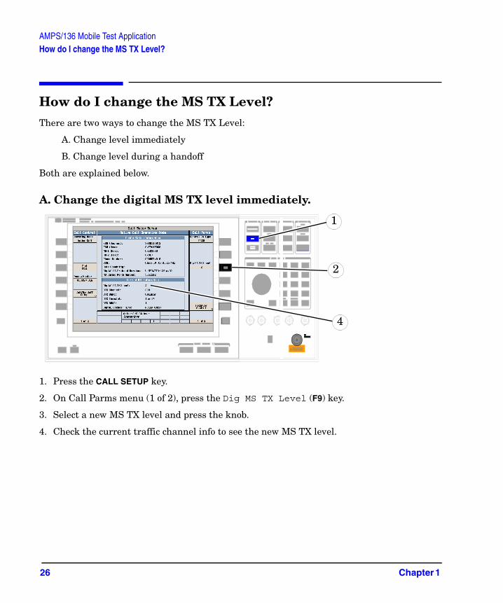
A. Change the digital MS TX level immediately.
1. Press the CALL SETUP key.
2. On Call Parms menu (1 of 2), press the Dig MS TX Level (F9) key.
3. Select a new MS TX level and press the knob.
4. Check the current traffic channel info to see the new MS TX level.
2
4
1
26 Chapter 1

AMPS/136 Mobile Test ApplicationHow do I change the MS TX Level?
B. Change the MS TX level during a handoff.
1. On Call Control menu, press the Call/Handoff Setup (F5) key.
2. Select and change the MS TX Level.
3. If you press the Execute Handoff (F5) key, the digital MS TX level changes.
4. If you abort the handoff by pressing the Close Menu (F6) key, digital MS TX level does not change.
3
2
4
Chapter 1 27
AMPS/136 Mobile Test ApplicationHow do I Perform a Handoff?
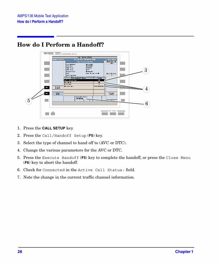
How do I Perform a Handoff?
1. Press the CALL SETUP key.
2. Press the Call/Handoff Setup (F5) key.
3. Select the type of channel to hand off to (AVC or DTC).
4. Change the various parameters for the AVC or DTC.
5. Press the Execute Handoff (F5) key to complete the handoff, or press the Close Menu (F6) key to abort the handoff.
6. Check for Connected in the Active Cell Status: field.
7. Note the change in the current traffic channel information.
4
56
3
28 Chapter 1

AMPS/136 Mobile Test ApplicationHow Do I Configure the Test Set for My Test System?
How Do I Configure the Test Set for My Test System?
A. Configure instrument information and setup.
1. Press the SYSTEM CONFIG key.
2. Press the Instrument Setup (F1) key.
3. Adjust an instrument setting and then press the Close Menu (F6) key.
3
Test ApplicationRevision
1
2
Chapter 1 29

AMPS/136 Mobile Test ApplicationHow Do I Configure the Test Set for My Test System?
B. Set amplitude offsets.
1. On the Configuration Summary Screen, press the RF IN/OUT Amptd Offset (F5) key.
2. On the RF IN/OUT Amplitude Offset screen, press the RF IN/OUT Amptd Offset Setup (F2) key.
3. Enter the amplitude offset for the test frequencies you use.
4. Press the Close Menu (F6) key.
5. Press the Return to Config Summary (F6) key.
2
4
30 Chapter 1

AMPS/136 Mobile Test ApplicationHow Do I Configure the Test Set for My Test System?
C. Check the message log.
1. Press the Message Log (F7) key and view the message log.
2. Press theReturn to Utilities (F12) key.
1
2
Chapter 1 31

AMPS/136 Mobile Test ApplicationHow Do I End a Call?
How Do I End a Call?
1. Press the CALL SETUP key.
2. Press the End Call (F3) key, or end the call from the mobile.
3. Check for Idle in the Active Cell Status: field.
2
32 Chapter 1

2 cdma2000/IS-2000 Mobile Test Application
33

cdma2000/IS-2000 Mobile Test ApplicationHow Do I Make Measurements on a Mobile?
How Do I Make Measurements on a Mobile?
A. Establish a call.
1. Press the blue SHIFT key.
2. Press the green PRESET key.
3. Connect the mobile to the Test Set.
4. Turn the mobile on and wait for it to camp.
5. On the mobile, press 1, 2, 3, then press send.
6. Check for Connected in the Active Cell field.
2
1
3
6
34 Chapter 2

cdma2000/IS-2000 Mobile Test ApplicationHow Do I Make Measurements on a Mobile?
B. Select measurements.
1. Press the Measurement selection key.
2. Highlight a measurement and press the knob.
3. Repeat steps 1 and 2 to add measurements.
2
1
The gray boxes indicate that the measurement is being made, but the results are not being displayed.
These black boxes indicate that access probe power measurement results are being displayed in the lower measurement window, and channel power results are being displayed in the upper measurement window.
Chapter 2 35

cdma2000/IS-2000 Mobile Test ApplicationHow Do I View a Graphical Measurement?
How Do I View a Graphical Measurement?
1. Select a measurement with a graphical view (for example Waveform Quality/Code Domain).
2. Press the Change View (F2) key.
3. Select the desired graphical view.
2
1
36 Chapter 2

cdma2000/IS-2000 Mobile Test ApplicationHow Do I Change the Measurement Setup?
How Do I Change the Measurement Setup?
A. Select a measurement.
1. Press the Measurement selection key.
2. Highlight a measurement to set up and press the knob.
1
2
Chapter 2 37

cdma2000/IS-2000 Mobile Test ApplicationHow Do I Change the Measurement Setup?
B. Set up the measurement.
1. Press the measurement’s setup (F1) key.
2. Highlight a parameter and press the knob.
3. Enter a value or selection and press the knob.
NOTE For statistical measurement results, change the Multi-Measurement Count parameter from “Off” to a number >1.
4. Press the Close Menu (F6) key.
1
4
2
3
38 Chapter 2
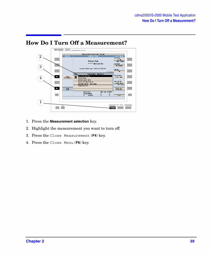
cdma2000/IS-2000 Mobile Test ApplicationHow Do I Turn Off a Measurement?
How Do I Turn Off a Measurement?
1. Press the Measurement selection key.
2. Highlight the measurement you want to turn off.
3. Press the Close Measurement (F4) key.
4. Press the Close Menu (F6) key.
3
1
4
2
Chapter 2 39
cdma2000/IS-2000 Mobile Test ApplicationHow Do I Set Up a Call?
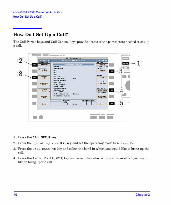
How Do I Set Up a Call?The Call Parms keys and Call Control keys provide access to the parameters needed to set up a call.
1. Press the CALL SETUP key.
2. Press the Operating Mode (F2) key and set the operating mode to Active Cell.
3. Press the Cell Band (F8) key and select the band in which you would like to bring up the call.
4. Press the Radio Config (F11) key and select the radio configuration in which you would like to bring up the call.
1
5
3
4
2
8
40 Chapter 2

cdma2000/IS-2000 Mobile Test ApplicationHow Do I Set Up a Call?
5. Check the rest of the Call Parms settings (keys F7 through F12) then press the More key to check the settings displayed on the 2 of 3 and 3 of 3 menus.
6. Make sure the cell settings, such as SID (System Identification) are compatible with the mobile station. See “How Do I Change Cell Information?” on page 43.
7. Turn on power to the mobile station and wait for an indication that it has found service.
8. Make a mobile station originated call or wait for the mobile station to perform power up registration, then press the Originate Call (F3) key.
9. Verify that the call is connected.
Chapter 2 41

cdma2000/IS-2000 Mobile Test ApplicationHow Do I Change Call Parameters?
How Do I Change Call Parameters?
1. Press the CALL SETUP key.
2. On the Call Parms menu (1 of 2) press any key.
3. Highlight a selection and press the knob. Enter a value.
4. Press the MORE key for additional call parameters.
1
2
4
42 Chapter 2

cdma2000/IS-2000 Mobile Test ApplicationHow Do I Change Cell Information?
How Do I Change Cell Information?There are three types of cell information: cell parameters, access parameters, and registration parameters.
A. Set cell parameters.
1. Select the Cell Parameters menu.
1. Press the CALL SETUP key.
2. Press the More key.
3. Press the Cell Info (F2) key.
4. Press the Cell Parameters (F2) key.
1
3
2
Chapter 2 43
cdma2000/IS-2000 Mobile Test ApplicationHow Do I Change Cell Information?
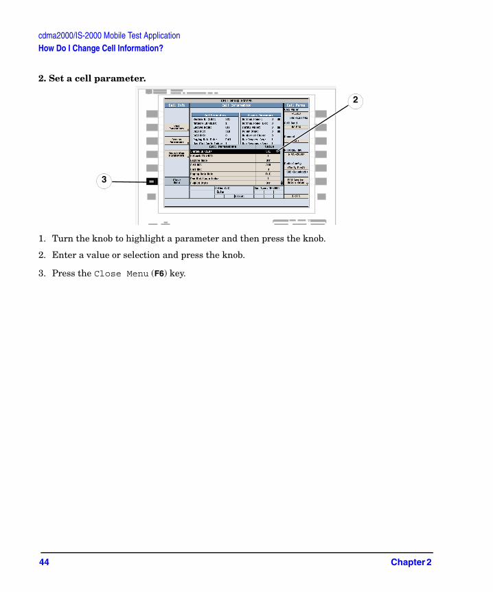
2. Set a cell parameter.
1. Turn the knob to highlight a parameter and then press the knob.
2. Enter a value or selection and press the knob.
3. Press the Close Menu (F6) key.
2
3
44 Chapter 2
cdma2000/IS-2000 Mobile Test ApplicationHow Do I Change Cell Information?
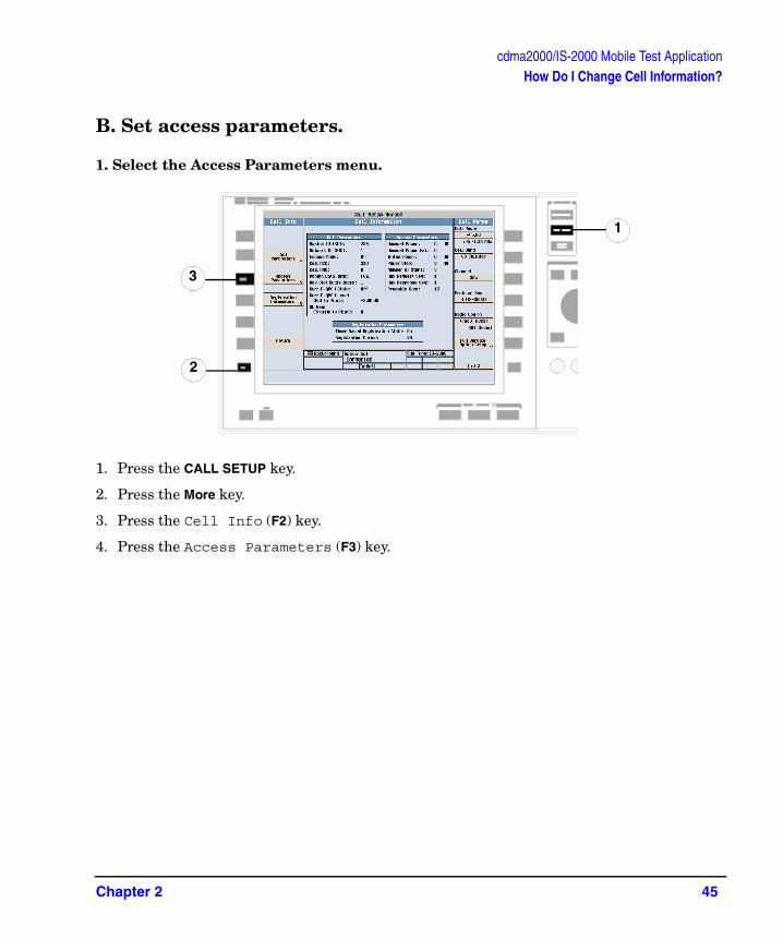
B. Set access parameters.
1. Select the Access Parameters menu.
1. Press the CALL SETUP key.
2. Press the More key.
3. Press the Cell Info (F2) key.
4. Press the Access Parameters (F3) key.
1
3
2
Chapter 2 45

cdma2000/IS-2000 Mobile Test ApplicationHow Do I Change Cell Information?
2. Set an access parameter.
1. Turn the knob to highlight a parameter and then press the knob.
2. Enter a value or selection and press the knob.
3. Press the Close Menu (F6) key.
2
3
46 Chapter 2
cdma2000/IS-2000 Mobile Test ApplicationHow Do I Change Cell Information?
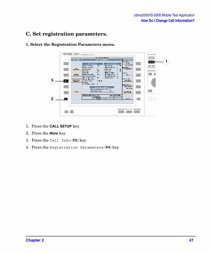
C. Set registration parameters.
1. Select the Registration Parameters menu.
1. Press the CALL SETUP key.
2. Press the More key.
3. Press the Cell Info (F2) key.
4. Press the Registration Parameters (F4) key.
1
3
2
Chapter 2 47

cdma2000/IS-2000 Mobile Test ApplicationHow Do I Change Cell Information?
2. Set a registration parameter.
1. Turn the knob to highlight a parameter and then press the knob.
2. Enter a value or selection and press the knob.
3. Press the Close Menu (F6) key.
1
3
48 Chapter 2
cdma2000/IS-2000 Mobile Test ApplicationHow Do I Change Code Channel Levels?
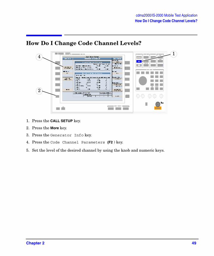
How Do I Change Code Channel Levels?
1. Press the CALL SETUP key.
2. Press the More key.
3. Press the Generator Info key.
4. Press the Code Channel Parameters (F2 ) key.
5. Set the level of the desired channel by using the knob and numeric keys.
41
2
Chapter 2 49

cdma2000/IS-2000 Mobile Test ApplicationHow Do I Perform a Handoff?
How Do I Perform a Handoff?
1. On the Call Setup screen, press the Call/Handoff Setup (F5) key.
2. Highlight the Handoff System Type parameter and select the desired system.
3. Highlight the Handoff Cell Band parameter and select the desired band.
4. Highlight the Handoff Channel parameter and select the desired channel.
5. Press the Execute Handoff (F5) key to complete the handoff, or the Close Menu (F6) key to abort the handoff.
6. Check for Connected in the Active Cell status field.
1
3
54
2
6
50 Chapter 2
cdma2000/IS-2000 Mobile Test ApplicationHow Do I Configure the Test Set for My Test System?
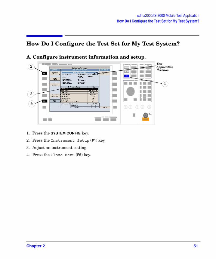
How Do I Configure the Test Set for My Test System?
A. Configure instrument information and setup.
1. Press the SYSTEM CONFIG key.
2. Press the Instrument Setup (F1) key.
3. Adjust an instrument setting.
4. Press the Close Menu (F6) key.
2Test Application Revision
1
4
3
Chapter 2 51

cdma2000/IS-2000 Mobile Test ApplicationHow Do I Configure the Test Set for My Test System?
B. Set amplitude offsets.
1. On the Configuration Summary screen (not shown), press the RF IN/OUT Amptd Offset (F5) key.
2. On the RF IN/OUT Amplitude Offset screen, press the RF IN/OUT Amptd Offset Setup (F2) key.
3. Enter the amplitude offset for the test frequencies you use.
4. Press the Close Menu (F6) key.
2
4
52 Chapter 2

cdma2000/IS-2000 Mobile Test ApplicationHow Do I Configure the Test Set for My Test System?
C. Check message log.
1. From any System Config screen, press the Message Log (F7) key and view the message log.
2. Press the Return (F12) key.
1
2
Chapter 2 53
cdma2000/IS-2000 Mobile Test ApplicationHow Do I End a Call?
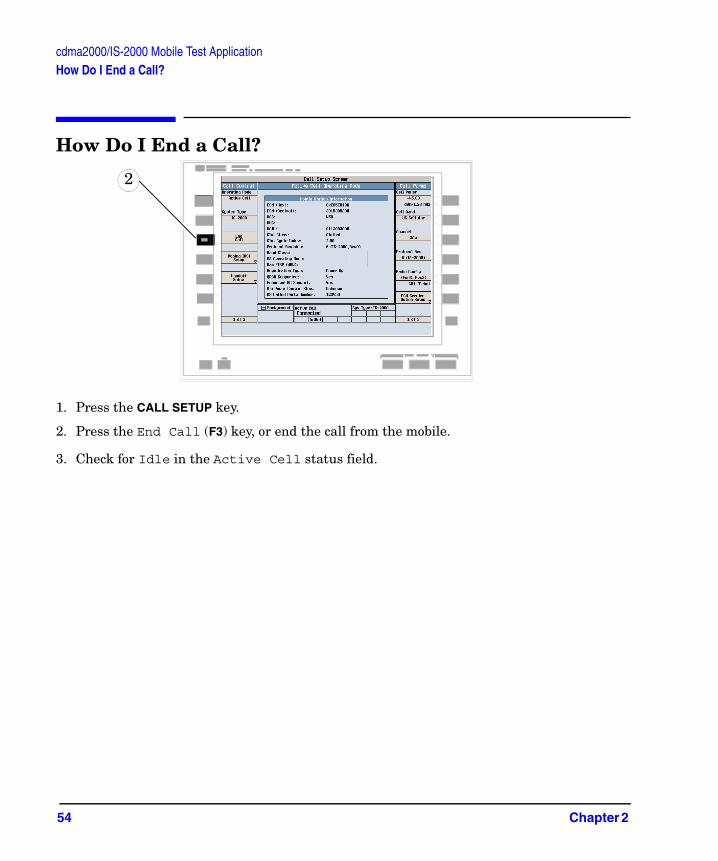
How Do I End a Call?
1. Press the CALL SETUP key.
2. Press the End Call (F3) key, or end the call from the mobile.
3. Check for Idle in the Active Cell status field.
2
54 Chapter 2

3 GPRS Mobile Test Application
55

GPRS Mobile Test ApplicationHow Do I Make Measurements on a Mobile?
How Do I Make Measurements on a Mobile?
A. Establish a data connection.
1. Press the blue SHIFT key.
2. Press the green Preset key.
3. Connect the mobile.
4. Turn the mobile on and wait for Attached in the Active Cell: field.
NOTE For mobiles that don’t perform GPRS attach automatically, set the mobile to data mode.
5. Press the Start Data Connection (F3) key and watch for the Active Cell: field changing to Transferring.
4
2
1
3
5
56 Chapter 3

GPRS Mobile Test ApplicationHow Do I Make Measurements on a Mobile?
B. Select measurements.
1. Press the Measurement selection key.
2. Highlight a measurement and press the knob.
3. Repeat steps 1 and 2 to add measurements.
The gray boxes indicate that the measurement is being made, but the results are not being displayed.
1
These black boxes indicate that phase and frequency error measurement results are being displayed in the lower measurement window, and bit error measurement results are being displayed in the upper measurement window.
Chapter 3 57
GPRS Mobile Test ApplicationHow Do I Change Measurement Setup?
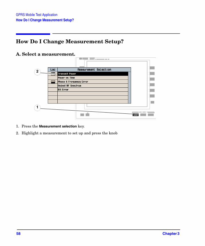
How Do I Change Measurement Setup?
A. Select a measurement.
1. Press the Measurement selection key.
2. Highlight a measurement to set up and press the knob
1
2
58 Chapter 3
GPRS Mobile Test ApplicationHow Do I Change Measurement Setup?
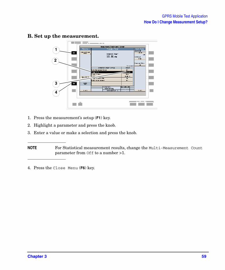
B. Set up the measurement.
1. Press the measurement’s setup (F1) key.
2. Highlight a parameter and press the knob.
3. Enter a value or make a selection and press the knob.
NOTE For Statistical measurement results, change the Multi-Measurement Count parameter from Off to a number >1.
4. Press the Close Menu (F6) key.
2
1
4
3
Chapter 3 59

GPRS Mobile Test ApplicationHow Do I Turn Off a Measurement?
How Do I Turn Off a Measurement?
1. Press the Measurement selection key.
2. Highlight the measurement you want to turn off.
3. Press the Close Measurement (F4) key.
4. Press the Close Menu (F6) key.
32
4
1
60 Chapter 3
GPRS Mobile Test ApplicationHow Do I Change Call Parameters?
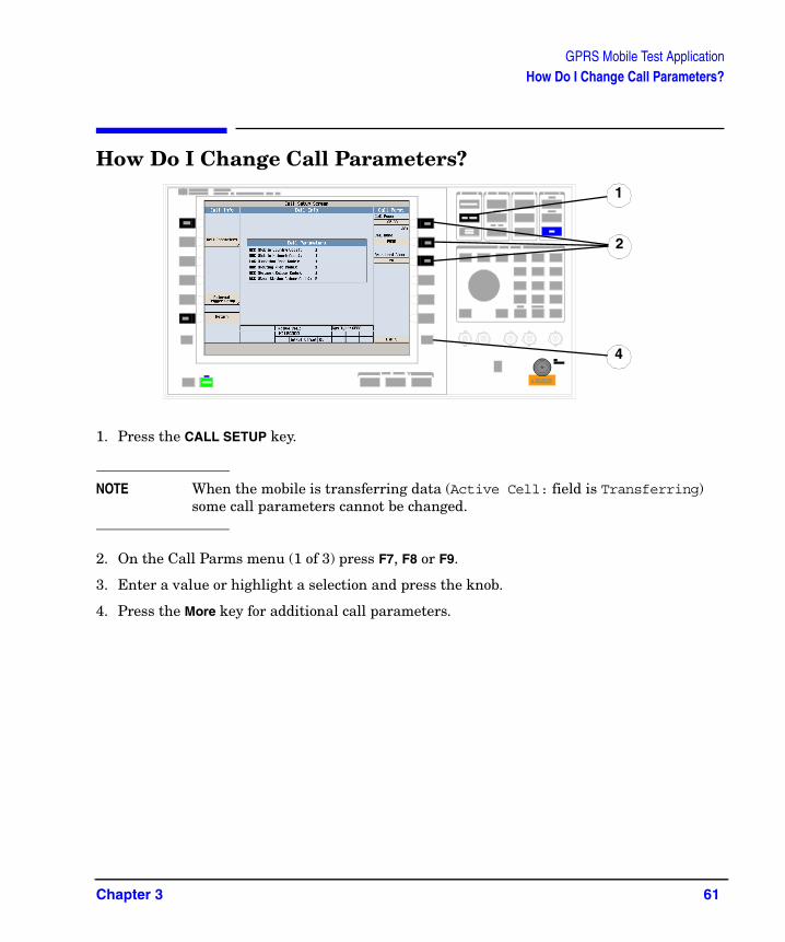
How Do I Change Call Parameters?
1. Press the CALL SETUP key.
NOTE When the mobile is transferring data (Active Cell: field is Transferring) some call parameters cannot be changed.
2. On the Call Parms menu (1 of 3) press F7, F8 or F9.
3. Enter a value or highlight a selection and press the knob.
4. Press the More key for additional call parameters.
1
2
4
Chapter 3 61

GPRS Mobile Test ApplicationHow Do I Change Cell Parameters?
How Do I Change Cell Parameters?
NOTE You can only change two cell parameters - 3 Digit MNC for PCS1900 and Guard Period Length. Other cell parameters such as MCC, MNC, and LAC are fixed. To change the 3 digit MNC for PCS1900 the cell must be set to off by pressing the CALL SETUP key, then Operating Mode (F1), and then selecting Cell Off.
A. Select the Cell Parameters menu.
1. Press the CALL SETUP key.
2. Press the Cell Info (F6) key.
3. Press the Cell Parameters (F2) key.
1
3
62 Chapter 3
GPRS Mobile Test ApplicationHow Do I Change Cell Parameters?
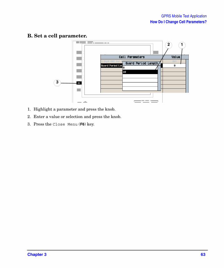
B. Set a cell parameter.
1. Highlight a parameter and press the knob.
2. Enter a value or selection and press the knob.
3. Press the Close Menu (F6) key.
12
3
Chapter 3 63
GPRS Mobile Test ApplicationHow Do I Perform a Handover?
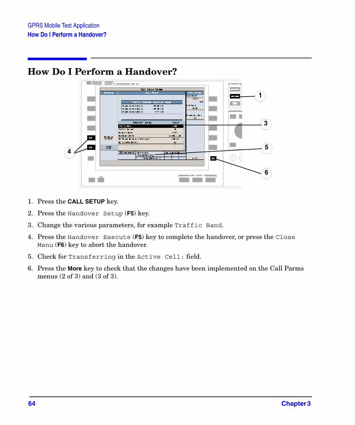
How Do I Perform a Handover?
1. Press the CALL SETUP key.
2. Press the Handover Setup (F5) key.
3. Change the various parameters, for example Traffic Band.
4. Press the Handover Execute (F5) key to complete the handover, or press the Close Menu (F6) key to abort the handover.
5. Check for Transferring in the Active Cell: field.
6. Press the More key to check that the changes have been implemented on the Call Parms menus (2 of 3) and (3 of 3).
4
3
5
6
1
64 Chapter 3

GPRS Mobile Test ApplicationHow Do I Change the MS TX Level?
How Do I Change the MS TX Level?There are two ways to change the MS TX Level:
A. Change the level immediately
B. Change the level during a handover
Both are explained below.
A. Change the MS TX level immediately.
1. Press the CALL SETUP key.
2. On the Call Parms menu (3 of 3) press the MS TX Level (F8) key.
3. Set a new MS TX level and press the knob.
4. Press the Close Menu (F6) key.
1
3
2
4
Chapter 3 65
GPRS Mobile Test ApplicationHow Do I Change the MS TX Level?
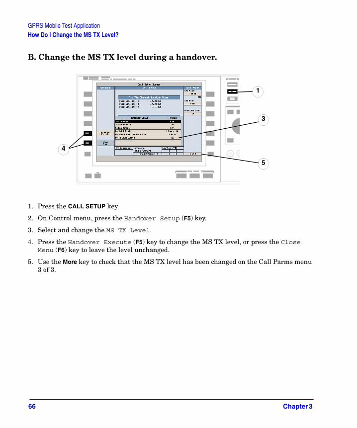
B. Change the MS TX level during a handover.
1. Press the CALL SETUP key.
2. On Control menu, press the Handover Setup (F5) key.
3. Select and change the MS TX Level.
4. Press the Handover Execute (F5) key to change the MS TX level, or press the Close Menu (F6) key to leave the level unchanged.
5. Use the More key to check that the MS TX level has been changed on the Call Parms menu 3 of 3.
3
4
1
5
66 Chapter 3
GPRS Mobile Test ApplicationHow Do I Configure the Test Set for My Test System?
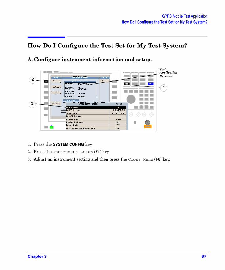
How Do I Configure the Test Set for My Test System?
A. Configure instrument information and setup.
1. Press the SYSTEM CONFIG key.
2. Press the Instrument Setup (F1) key.
3. Adjust an instrument setting and then press the Close Menu (F6) key.
Test Application Revision
1
2
3
Chapter 3 67

GPRS Mobile Test ApplicationHow Do I Configure the Test Set for My Test System?
B. Set amplitude offsets.
1. On the Configuration Summary screen, press the RF IN/OUT Amptd Offset (F5) key.
2. On the RF IN/OUT Amplitude Offset screen, press the RF IN/OUT Amptd Offset Setup (F2) key.
3. Enter the amplitude offsets for the test frequencies you use.
4. Press the Close Menu (F6) key.
5. Press the Return (F6) key to return to the Configuration Summary screen.
2
4
68 Chapter 3

GPRS Mobile Test ApplicationHow Do I Configure the Test Set for My Test System?
C. Check the message log.
1. Press the Message Log (F7) key and view the message log.
2. Press the Return (F12) key.
1
2
Chapter 3 69
GPRS Mobile Test ApplicationHow Do I End the Data Connection?
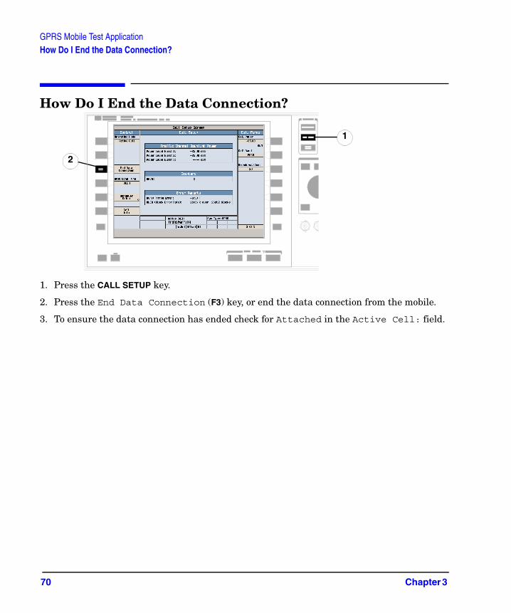
How Do I End the Data Connection?
1. Press the CALL SETUP key.
2. Press the End Data Connection (F3) key, or end the data connection from the mobile.
3. To ensure the data connection has ended check for Attached in the Active Cell: field.
2
1
70 Chapter 3

4 GSM Mobile Test Application
71
GSM Mobile Test ApplicationHow Do I Make Measurements on a Mobile?
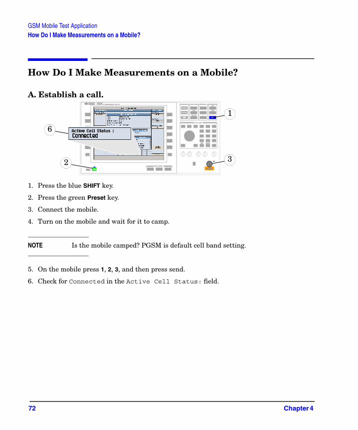
How Do I Make Measurements on a Mobile?
A. Establish a call.
1. Press the blue SHIFT key.
2. Press the green Preset key.
3. Connect the mobile.
4. Turn on the mobile and wait for it to camp.
NOTE Is the mobile camped? PGSM is default cell band setting.
5. On the mobile press 1, 2, 3, and then press send.
6. Check for Connected in the Active Cell Status: field.
6
2
1
3
72 Chapter 4
GSM Mobile Test ApplicationHow Do I Make Measurements on a Mobile?
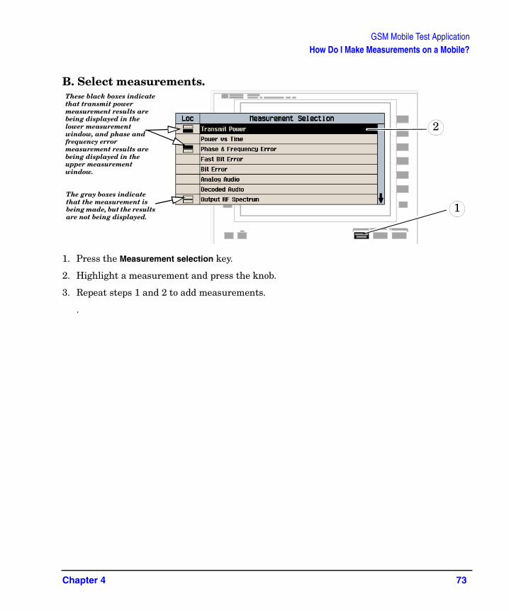
B. Select measurements.
1. Press the Measurement selection key.
2. Highlight a measurement and press the knob.
3. Repeat steps 1 and 2 to add measurements.
.
2
1The gray boxes indicate that the measurement is being made, but the results are not being displayed.
These black boxes indicate that transmit power measurement results are being displayed in the lower measurement window, and phase and frequency error measurement results are being displayed in the upper measurement window.
Chapter 4 73

GSM Mobile Test ApplicationHow Do I Change a Measurement’s Setup?
How Do I Change a Measurement’s Setup?
A. Select a measurement.
1. Press the Measurement selection key.
2. Highlight a measurement to setup and press the knob.
1
2
74 Chapter 4

GSM Mobile Test ApplicationHow Do I Change a Measurement’s Setup?
B. Set up the measurement.
1. Press the measurement’s setup key (F1).
2. Highlight a parameter and press the knob.
3. Enter a value or make a selection and press the knob.
NOTE For statistical measurement results, change the Multi-Measurement Count parameter from Off to a number >1.
4. Press the Close Menu (F6) key.
3
2
1
4
Chapter 4 75

GSM Mobile Test ApplicationHow Do I Turn Off a Measurement?
How Do I Turn Off a Measurement?
1. Press the Measurement selection key.
2. Highlight the measurement you want to turn off.
3. Press the Close Measurement (F4) key.
4. Press the Close Menu (F6) key.
3
2
1
4
76 Chapter 4

GSM Mobile Test ApplicationHow Do I Change Cell Parameters?
How Do I Change Cell Parameters?
A. Select the Cell Parameters menu.
1. Press the CALL SETUP key.
2. Press the Cell Info (F5) key.
3. Press the Cell Parameters (F2) key.
3
1
Chapter 4 77
GSM Mobile Test ApplicationHow Do I Change Cell Parameters?
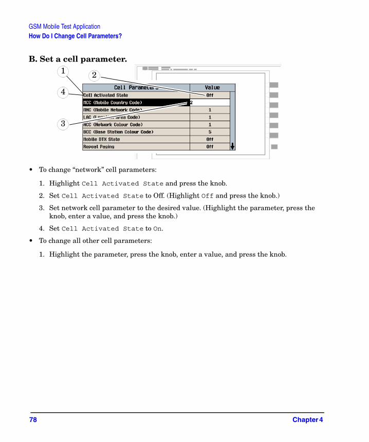
B. Set a cell parameter.
• To change “network” cell parameters:
1. Highlight Cell Activated State and press the knob.
2. Set Cell Activated State to Off. (Highlight Off and press the knob.)
3. Set network cell parameter to the desired value. (Highlight the parameter, press the knob, enter a value, and press the knob.)
4. Set Cell Activated State to On.
• To change all other cell parameters:
1. Highlight the parameter, press the knob, enter a value, and press the knob.
4
1
3
2
78 Chapter 4
GSM Mobile Test ApplicationHow Do I Change Call Parameters?
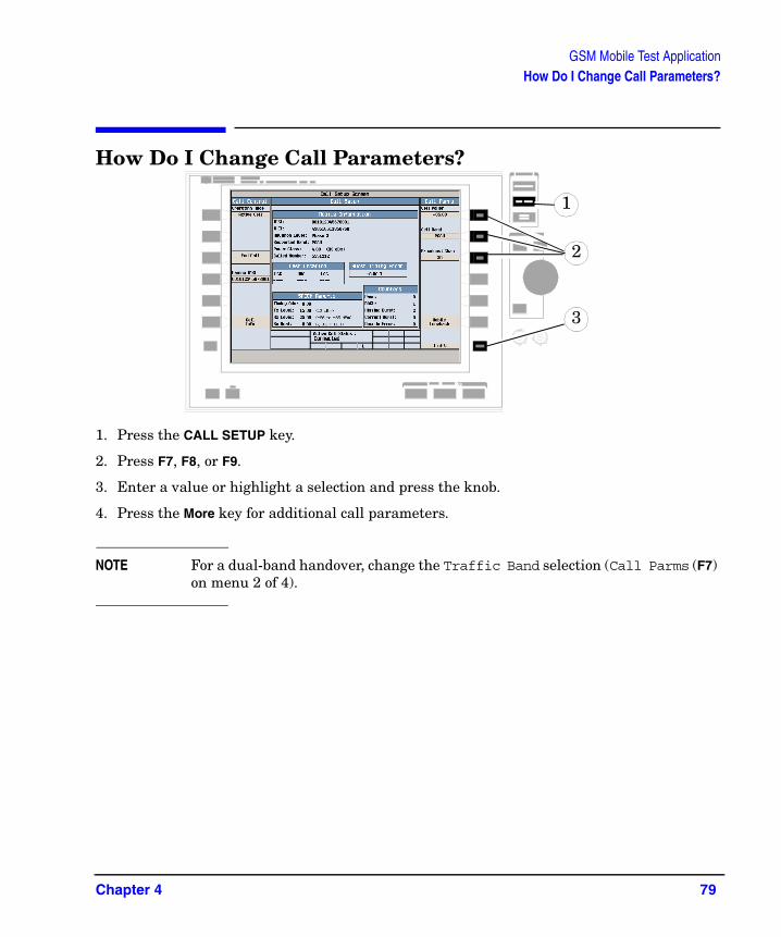
How Do I Change Call Parameters?
1. Press the CALL SETUP key.
2. Press F7, F8, or F9.
3. Enter a value or highlight a selection and press the knob.
4. Press the More key for additional call parameters.
NOTE For a dual-band handover, change the Traffic Band selection (Call Parms (F7) on menu 2 of 4).
1
2
3
Chapter 4 79
GSM Mobile Test ApplicationHow Do I Configure the Test Set for My Test System?
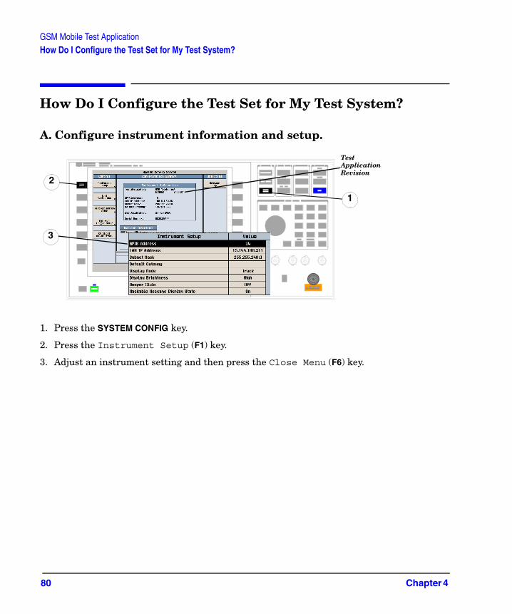
How Do I Configure the Test Set for My Test System?
A. Configure instrument information and setup.
1. Press the SYSTEM CONFIG key.
2. Press the Instrument Setup (F1) key.
3. Adjust an instrument setting and then press the Close Menu (F6) key.
Test Application Revision
1
2
3
80 Chapter 4
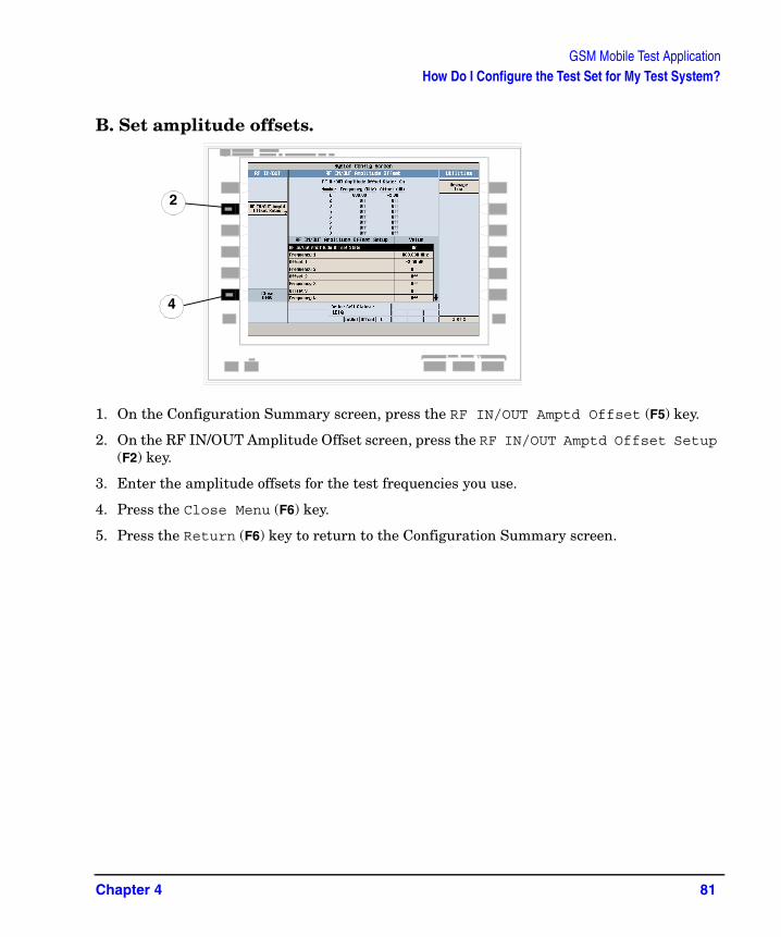
GSM Mobile Test ApplicationHow Do I Configure the Test Set for My Test System?
B. Set amplitude offsets.
1. On the Configuration Summary screen, press the RF IN/OUT Amptd Offset (F5) key.
2. On the RF IN/OUT Amplitude Offset screen, press the RF IN/OUT Amptd Offset Setup (F2) key.
3. Enter the amplitude offsets for the test frequencies you use.
4. Press the Close Menu (F6) key.
5. Press the Return (F6) key to return to the Configuration Summary screen.
2
4
Chapter 4 81

GSM Mobile Test ApplicationHow Do I Configure the Test Set for My Test System?
C. Check the message log.
1. Press the Message Log (F7) key and view the message log.
2. Press the Return (F12) key.
1
2
82 Chapter 4

GSM Mobile Test ApplicationHow Do I End a Call?
How Do I End a Call?
1. Press the CALL SETUP key.
2. Press the End Call (F3) key, or end the call from the mobile.
3. Check for Idle in the Active Cell Status: field.
2
Chapter 4 83

GSM Mobile Test ApplicationHow Do I End a Call?
84 Chapter 4

5 GSM_AMPS/136 Fast Switch
85
GSM_AMPS/136 Fast SwitchHow Do I Switch Formats?
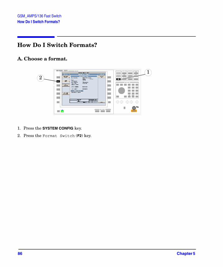
How Do I Switch Formats?
A. Choose a format.
1. Press the SYSTEM CONFIG key.
2. Press the Format Switch (F2) key.
12
86 Chapter 5
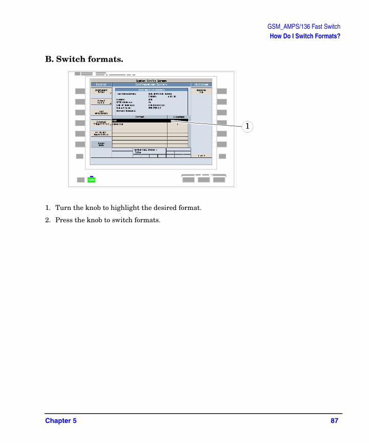
GSM_AMPS/136 Fast SwitchHow Do I Switch Formats?
B. Switch formats.
1. Turn the knob to highlight the desired format.
2. Press the knob to switch formats.
1
Chapter 5 87

GSM_AMPS/136 Fast SwitchHow Do I Switch Formats?
88 Chapter 5

6 Switching Test Applications
89

Switching Test ApplicationsHow Do Switch Test Applications?
How Do Switch Test Applications?
A. Choose a test application.
1. Press the SYSTEM CONFIG key.
2. Press the Test Application (F3) key.
3. Press the Test Application Switch (F1) key, and wait for the Test Application, Revision, License menu to appear. There is a slight pause before the menu is displayed.
1
2
3
90 Chapter 6

Switching Test ApplicationsHow Do Switch Test Applications?
4. Turn the knob to highlight a test application name, and press the knob to select the TA.
B. Switch test applications.
1. Turn the knob to highlight Yes in the Switch Now? menu.
2. Press the knob to switch test applications.
3. Wait for the test set to reboot in the new test application.
4
1
Chapter 6 91