agilent e6702b cdma2000/is-95/amps lab application · agilent e6702b cdma2000/is-95/amps ... •...
TRANSCRIPT

Data Sheet
Agilent E6702B cdma2000/IS-95/AMPS Lab Application
Accelerate your design of cdma2000wireless devices
Key Features
• External protocol logging and analysis software finds and resolves difficult signaling functionality and timing issues faster
• Simulate two CDMA base station signals, giving you the flexibility to test soft and softer handoff capabilities
• Troubleshoot design issues or test setup problems with enhanced frame error rate measurement
• Data channel connectivity tests high-speed packet data connection to a network
• External, high-precision digital fading when used with the Agilent Baseband Studio Channel Simulator
• The E6702B includes all E1962B test application manufacturing-specific features and measurements, helping smooth the transition from development to manufacturing
What’s new?
• Hybrid mode support with full verification capabilities when used in conjunction with another E5515C running the E6706A 1xEV-DO lab application and the Software Concepts MOB-IP-SIM
• Multi-unit synchronization for supporting idle handoff tests and hybrid mode operation
• MEID support for testing mobiles equipped with the new mobile equipment ID rather than ESN
• CDMA authentication enables verification of authentication call processing functions such as SSD update, unique challenge, and authenticated call procedures
• Settable system time allows the user to set any desiredsystem time and date for CDMA modes
• Real time vocoder allows functional test of speech connections using the 13 k or EVRC vocoders
• Support for the new band class 0 allows testing mobiles that conform to this revised frequency plan, including channels for the Japanese market
• Enhanced AMPS measurements includes new, one-button call processing send maintenance order and send alert order commands along with dedicated signaling tone, DTMF tone, and wideband data measurements
For use with the E5515C (8960) mainframe

2
E6702B Functionality OverviewMeet aggressive time-to-market and production schedules Growing demand for high-speed data services means theroll out of cdma2000 wireless devices is essential. TheAgilent E6702B cdma2000 Lab Application, combinedwith the E5515C (8960) test set provides the criticalcapabilities needed to verify and ensure quality RF performance in your cdma2000, IS-95, and AMPSdevices. This lab application, designed for high-volumemanufacturing and wireless device development, allowsyou to finalize product designs and minimize time-to-volume.
Comprehensive protocol supportThe E6702B supports numerous protocol features toenable fast and accurate regression test of phones. Forexample, Service Option 033 support provides the abilityfor the test set to function as a live packet data network.Simply connect to an external server or the internet viathe rear panel LAN port, and you can test packet dataconnections on IS-2000 mobile stations. Support for1/8th rate traffic gating mode allows accurate talk timetesting. Comprehensive SMS capability allows full testingof a mobile’s SMS capabilities according to industry teststandards. Other features include IS-2000 Release A protocol support, full hybrid mode test capability (inconjunction with another E5515C running the E6706A1xEV-DO lab application), CDMA authentication capability, real time vocoder that supports functionalverification, and caller ID.
CDMA forward link emulationComprehensive signal generation capabilities includingall applicable CDMA channels, modulation, and anAWGN source (1.8 MHz minimum bandwidth). Supportis also included for the new cdma2000 release A forwardlink channels such as the F-BCCH and F-CCCH. Flexibleuser control of the forward link emulation is providedthrough easy-to-use front panel control and remoteGPIB.
CDMA transmitter tests• Maximum power• Minimum power• Multi-code waveform quality• Handoff waveform quality• Open loop power accuracy• Open loop power calibration• Access probe power• Graphical access probe power• Code domain power • Gated power• Code channel timing and phase• Spurious emissions• Time response of open loop• Tx dynamic power
CDMA receiver tests• Fundamental/traffic channel sensitivity• Demodulation of F-FCH in multipath fading• Demodulation of F-FCH in multipath fading with
closed loop power control (FPC_Mode=000)• Demodulation of F-FCH in multipath fading with
outer loop and closed loop power control (FPC_Mode=000)
• Supplemental channel sensitivity• Dynamic range• Demodulation with AWGN• Slotted paging channel MER
AMPS transmitter tests• RF power output• RF frequency and frequency error• FM modulation limiting• FM deviation and distortion• Audio frequency response• Audio distortion• FM hum and noise• SAT deviation and frequency error• Compressor response• Signaling tone frequency and deviation• DTMF symbol, frequency, and deviation• Wideband data deviation
AMPS receiver tests• SINAD• Audio frequency response• Audio distortion• FM hum and noise• Expander response
Fading testsOption 004 adds a rear panel digital bus that enablesfading when used with Agilent’s Baseband Studio forfading solution. In conjunction with the N5101ABaseband Studio PCI card and the N5115A BasebandStudio for fading software, the E6702B provides receiverfading tests with unprecedented accuracy and repeata-bility at a very attractive price point. Baseband I/Q datafrom the E5515C is sent via the digital bus to theN5101A fading card in an external PC. The N5115A fading software configures the PCI card to perform theuser-selected fading profile. After digital fading, AWGNcan be digitally added to the waveform. The resultingwaveform is then returned to the test set via the digitalbus for modulation. This solution eliminates almost allassociated calibrations and provides rock-solid repeata-bility. Typical Eb/Nt repeatability for fading tests withfast forward power control enabled is less than 0.1 dB!
Get the proven benefits of the Agilent 8960 test setBecause this cdma2000 test solution is based on thehigh-performance 8960 Series 10 test set, you gain theadditional benefits of extremely fast measurementspeed, ease of programming, accuracy, reliability, andworldwide service and support. These proven featureshelp you shorten test development time, increasethroughput, and minimize support costs.

3
Analog specificationsAMPS active cell call processing functionalityCall control (“one button commands”):
register, BS call originate, BS call disconnect, MS call originate (auto answer), and MS call disconnect
Call setup parameters: control channel, voice channel, SID, SAT, and power level
Handoff support: hard handoff to new channelRegistration reported mobile information: ESN in
decimal, ESN in hex, MIN1, MIN2, phone number, station class mark (SCM), and called number
AMPS test mode functionalityUsage: the mobile station must be setup on a channel
without the test set (using internal test mode commands in the mobile). The test set provides RF generator output and RF and audio analysis input. This mode provides no signaling
Spectrum monitorInput frequency ranges:
• 411 to 420 MHz• 450 to 484 MHz• 824 to 934 MHz• 1750 to 1780 MHz• 1850 to 1980 MHz
Reference level: auto or manualManual reference level range: +37 to –50 dBmDisplay dB per division: 20.0 to 0.1 dB per divisionLevel measurement accuracy: (calibrated against
average power and within ±10 degrees of calibrationtemperature. Calibration must occur between 20 to 55 °C): typically < ±1.0 dB 15 to 55 °C
Display frequency span and resolution bandwidth(coupled):
• 0 Hz span• 125 kHz span 300 Hz RBW• 500 kHz span 1 kHz RBW• 1.25 MHz span 1 kHz RBW• 2.5 MHz span 10 kHz RBW• 4 MHz span 30 kHz RBW• 5 MHz span 30 kHz RBW• 10 MHz span 100 kHz RBW• 12 MHz span 100 kHz RBW• 20 MHz span 100 kHz RBW• 40 MHz span 300 kHz RBW• 80 MHz span 1 MHz RBW• 100 MHz span 5 MHz RBW
Trigger: immediate, RF rise, protocol, or externalTrigger arm: single or continuousTrigger delay: –50 to 50 msZero span trace time: 60 µs to 70 msZero span resolution bandwidth: 100 kHz, 300 kHz, or
1 MHzDetector: peak detection or sample detectionTrace mode: clear write, max hold, or min holdMarkers: three user markersMarker modes: off, position, or deltaMarker functions: peak search, marker to expected
frequency, and marker to expected power
Technical SpecificationsThese specifications apply to an E5515C mainframe withOption 003 for serial number US40410101, GB40410101,or higher when used with an E6702B lab application offirmware revision B.03.21 or higher.
Specifications describe the test set’s warranted perform-ance and are valid for the unit's operation within thestated environmental ranges unless otherwise noted. All specifications are valid after a 30-minute warm-upperiod of continuous operation.
Supplemental characteristics are intended to providetypical, but non-warranted, performance parametersthat may be useful in applying the instrument. Thesecharacteristics are shown in italics and labeled as “typical”, or “supplemental”. All units shipped from thefactory meet these typical numbers at 25 °C ambienttemperature without including measurement uncertainty.
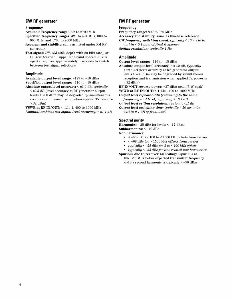
CW RF generatorFrequencyAvailable frequency range: 292 to 2700 MHz Specified frequency ranges: 421 to 494 MHz, 800 to
960 MHz, and 1700 to 2000 MHzAccuracy and stability: same as listed under FM RF
generatorTest signal: CW, AM (56% depth with 20 kHz rate), or
DSB-SC (carrier + upper side-band spaced 20 kHz apart); requires approximately 3 seconds to switch between test signal selections
AmplitudeAvailable output level range: –127 to –10 dBmSpecified output level range: –116 to –15 dBmAbsolute output level accuracy: < ±1.0 dB, typically
< ±0.5 dB (level accuracy at RF generator output levels > –30 dBm may be degraded by simultaneous reception and transmission when applied Tx power is> 32 dBm)
VSWR at RF IN/OUT: < 1.14:1, 400 to 1000 MHzNominal ambient test signal level accuracy: < ±1.1 dB
FM RF generatorFrequencyFrequency range: 800 to 960 MHz Accuracy and stability: same as timebase referenceCW frequency switching speed: typically < 10 ms to be
within < 0.1 ppm of final frequencySetting resolution: typically 1 Hz
AmplitudeOutput level range: –116 to –15 dBmAbsolute output level accuracy: < ±1.0 dB, typically
< ±0.5 dB (level accuracy at RF generator output levels > –30 dBm may be degraded by simultaneous reception and transmission when applied Tx power is> 32 dBm)
RF IN/OUT reverse power: +37 dBm peak (5 W peak)VSWR at RF IN/OUT: < 1.14:1, 400 to 1000 MHzOutput level repeatability (returning to the same
frequency and level): typically < ±0.1 dBOutput level setting resolution: typically 0.1 dBOutput level switching time: typically < 50 ms to be
within 0.1 dB of final level
Spectral purityHarmonics: –25 dBc for levels < –17 dBmSubharmonics: < –40 dBcNon-harmonics:
• < –55 dBc for 100 to < 1500 kHz offsets from carrier• < –68 dBc for > 1500 kHz offsets from carrier• typically < –55 dBc for 3 to < 100 kHz offsets• typically < –53 dBc for line-related non-harmonics
Spurious due to receiver LO leakage: spurious at 105 ±2.5 MHz below expected transmitter frequency and its second harmonic is typically < –50 dBm
4

FM and SAT signal generationFM rate range: 100 Hz to 20 kHzFM deviation range: 0 to 20 kHz for combined SAT,
internal, and external deviationResidual FM: < 7 Hz rms in a CCITT bandwidthInternal FM accuracy: < ±(3.5% + residual FM) at a
1 kHz rateExternal FM accuracy: < ±(5% + residual FM) at a 1 kHz
rateFM flatness: < ±5% relative to a 1 kHz rateFM distortion (THD plus noise): < 0.5% for > 4 kHz
deviation at a 1 kHz rate in a CCITT bandwidthExternal FM input sensitivity: 20 kHz deviation per VMaximum external FM input level: 1 V peakSAT frequencies: 5970, 6000, or 6030 HzSAT deviation: fixed at 2 kHzFM rate resolution: typically 5 HzFM deviation resolution: typically 5 Hz
Audio generatorFrequencyOperating range: 100 Hz to 20 kHz, typically 1 Hz to
20 kHzAccuracy: same as timebase referenceFrequency resolution: typically 0.1 Hz
Output level (from AUDIO OUTPUT connector)Ranges: 0 to 1 V peak, 1 to 9 V peak into > 600 ΩAccuracy: < ±(1.5% of setting + resolution) when output
is DC coupledDistortion: < 0.1% for 0.2 to 9 V peak into > 600 ΩCoupling mode: selectable as DC or AC (5 µF in series
with output)Maximum output current: typically 100 mA peak into 8 ΩOutput impedance: typically < 1.5 Ω at 1 kHz when
output is DC coupledDC offset (when output is DC coupled):
• typically < 1 mV peak for 0 to 1 V peak• typically < 10 mV peak for 1 to 9 V peak
Output level resolution: typically < 0.5 mV for 0 to 1 V peak output, < 5.0 mV for 1 to 9 V peak output
AMPS RF analyzer Unless otherwise noted, all specifications apply to frequencies of 800 to 960 MHz for signals with peakinput power at the test set’s RF IN/OUT not higher than+34 dBm and temperatures of 0 to 55 °C. Input signal Tx power at the test set’s RF IN/OUT must be within ±3 dB of the test set’s expected power for warrantedperformance.
Analog Tx power measurementTypes of signals measured: CW or AMPS signals with or
without SATFrequency capture range: signal must be within
±100 kHz of test set’s expected frequencyMaximum input level: +37 dBm peak (5 W peak)Minimum input level: > –30 dBmExtended amplitude range: typically results are
provided for signals at test set’s RF IN/OUT with analog Tx power within –10 and +5 dB of expected power
Measurement accuracy (for 20 to 55 °C):< ±0.32 dB for 800 to 960 MHz, typically < ±0.14 dB for 800 to 960 MHz
Measurement resolution: typically 0.01 dBMeasurement repeatability: typically < ±0.1 dBVSWR at RF IN/OUT: < 1.14:1, 800 to 1000 MHzMeasurement trigger source: immediateAvailable result: output powerMulti-measurement capabilities: 1 to 999 bursts,
minimum, maximum, average, and standard deviationresults
Concurrency capabilities: analog Tx power measurements can be made concurrently with all analog and audio measurements
5

6
Frequency modulation measurementTypes of signals measured: analog and AMPS signals
with or without SATFrequency capture range: signal must be within
±2.5 kHz of test set’s expected frequencyDeviation and frequency measurement rate range:
100 Hz to 15 kHzDistortion measurement rate range: 100 Hz to 10 kHzMeasurement deviation range: 0 to 16 kHzMinimum input level: signal at test set’s RF IN/OUT
must have analog Tx power > –15 dBmrms deviation measurement accuracy: < ±(2% of
reading + residual FM effects)Peak deviation measurement accuracy: < ±(3% of
reading + residual FM effects)Distortion measurement accuracy: < ±12% of reading
(±1.0 dB) ± residual FM effectsFrequency measurement accuracy (for input signals
with ratio of deviation to residual FM > 30 dB): • < ±0.1 Hz averaged over 10 measurements• < ±1.0 Hz for a single measurement
Residual FM: < 7 Hz rms in a C-message bandwidth, < 1.5 Hz rms in a 100 Hz bandwidth using the tunableband pass filter
Measurement trigger source: immediateMeasurement detector: selectable choices of rms,
peak+, and peak–, peak +/– max, peak +/– max/2Measurement gate time: 50 ms to 6.0 s with 50 ms
resolution; default value of 50 msMeasurement filtering: settable choices of none, 100 Hz
bandwidth band pass tunable over 300 Hz to 15 kHz, C-message, 50 Hz to 3 kHz band pass, 50 Hz to 15 kHzband pass,or 300 Hz to 15 kHz band pass
Measurement de-emphasis: 750 µs settable as off or onMeasurement expandor: settable as off or onAvailable results: FM deviation level, FM distortion, and
modulation frequencyMulti-measurement capabilities: 1 to 999 measure-
ments, minimum, maximum, average, and standard deviation results
Concurrency capabilities: frequency modulation measurements can be made concurrently with all analog and audio measurements
Deviation measurement resolution: typically 1 HzDistortion measurement resolution: typically 0.1%Frequency measurement resolution: typically 0.1 HzExternal audio output: selectable source for the front
panel Audio Out port of either the audio source (default) or the demodulated FM output
Frequency stability measurementTypes of signals measured: analog and AMPS signals
with or without SAT and with frequency modulation index (β) < 3.0 radians
Frequency capture range: signal must be within ±200 kHz of test set’s expected frequency
Measurement rate range: 100 Hz to 15 kHzMinimum input level: signal at test set’s RF IN/OUT
must have analog Tx power > –30 dBm
Frequency and frequency error measurement accuracy:
Measurement Input signal Input signal accuracy modulation frequency range< ±(1 Hz + time- None 800 to 960 MHzbase accuracy)
< ±(10 Hz + Frequency 800 to 960 MHztime-base accuracy) modulation with
β < 3.0 radians
Measurement accuracy: typically < ±(1 Hz + timebase accuracy) for an input signal with SAT, < ±(3.3 Hz + timebase accuracy) for an input signal with β = 1 radian
Measurement trigger source: immediateAvailable results: RF frequency and RF frequency errorMulti-measurement capabilities: 1 to 999 measure-
ments, minimum, maximum, average, and standard deviation in Hz for all results and worst case RF frequency error in ppm result
Concurrency capabilities: frequency stability measure-ments can be made concurrently with all analog and audio measurements
Measurement resolution for frequency and frequency error measurement results in Hz: typically 1 Hz
Measurement resolution for frequency error measurement result in ppm: typically 0.01 ppm

7
Signaling tone measurementTypes of signals measured: AMPS 10 kHz signaling tone
with or without SATMeasurement setup requirements: in the AMPS active
cell mode, the user must trigger the test set to send a maintenance order in order to force the DUT to transmit the signaling tone; in the AVC test mode, the user must force the DUT to transmit the signaling tone using a test mode in the DUT
Frequency capture range: RF signal must be within ±2.5 kHz of test set’s expected frequency
Measurement deviation range: 0 to 16 kHzMinimum input level: signal at test set’s RF IN/OUT
must have analog Tx power > –15 dBmPeak deviation measurement accuracy: same as FM
measurementResidual FM: same as FM measurementMeasurement trigger source: immediateMeasurement detector: peak+ and peak–Measurement filtering: fixed to 100 Hz band pass filter
centered on the 10 kHz signaling toneAvailable results: signaling tone peak+ and peak–
deviation level, signaling tone frequency, and signalingtone frequency error
DTMF measurementTypes of signals measured: AMPS DTMF modulated
signalsMeasurement setup requirements: in the AMPS active
cell mode or AVC test mode, the user must trigger the DUT to transmit the desired DTMF symbols
Supported DTMF symbols: 1, 2, 3, A, 4, 5, 6, B, 7, 8, 9, C, *, 0, #, and D
DTMF symbol frequency capture range: DTMF symbolsindividual high and low tones must be within ±2% of their defined frequencies for correct detection
DTMF symbol defined frequencies:1209 Hz 1336 Hz 1477 Hz 1633 Hz
697 Hz 1 2 3 A
770 Hz 4 5 6 B
852 Hz 7 8 9 C
941 Hz * 0 # D
Measurement deviation range: 2.0 to 6.0 radiansMinimum input level: signal at test set’s RF IN/OUT
must have analog Tx power > –15 dBmPeak deviation measurement accuracy: same as FM
measurementResidual FM: same as FM measurementMeasurement trigger source: immediateMeasurement detector: rms, peak+, peak–, peak +/–
max, and peak +/– max/2Measurement gate time: 100 ms to 6.0 s with 100 ms
resolution; default value of 2.0 sMeasurement filtering: fixed to 100 Hz band pass filter
centered on the symbol’s nominal high and low tone frequencies
Available results: reports the following parameters for up to 16 DTMF symbols (those captured during the measurement gate time): detected symbol; low tone frequency, frequency error, radian deviation; high tone frequency, frequency error, radian deviation; symbol on time; and symbol off time
Wideband data deviation measurementTypes of signals measured: AMPS wideband data burstsMeasurement setup requirements: in the AMPS active
cell mode, the user must arm the measurement and then force the DUT to send a wideband data burst by changing the MS Tx level (causes the test set to send asignaling message that the DUT must respond to); in the AVC test mode, the user must force the DUT to transmit a wideband data burst using a test mode in the DUT
Frequency capture range: RF signal must be within ±2.5 kHz of test set’s expected frequency
Measurement deviation range: 4 to 16 kHzMinimum input level: signal at test set’s RF IN/OUT
must have analog Tx power > –15 dBmPeak deviation measurement accuracy: same as FM
measurementResidual FM: same as FM measurementMeasurement trigger source: immediateMeasurement detector: peak+ and peak–Measurement gate time: 100 ms to 6.0 s with
100 ms resolution; default value of 2.0 sMeasurement filtering: fixed to 50 Hz high-pass filterAvailable results: wideband data peak+ and peak–
frequency deviation, and wideband data settled peak+and peak– frequency deviation; settled results are taken 30 ms after the detected front edge of the wideband data burst

8
Audio analyzer specificationsAll specifications for the audio analyzer apply to signalspresent at test set’s AUDIO IN ports.Audio analyzer de-emphasis: 750 µs, de-emphasis
settable as off or onAudio analyzer expandor: settable as off or on with
reference level setting of 10 mV to 10 VAudio analyzer filters: settable choices of none,
C-message, 50 Hz to 15 kHz band pass, 300 Hz to 15 kHz band pass, or 100 Hz bandwidth tunable band pass tunable over 300 Hz to 15 kHz
Audio level measurementTypes of signals measured: sinusoidal audio signalsMeasurement frequency range: 100 Hz to 15 kHzAUDIO IN level range: 7.1 mV to 20 V peak (5 mV to
14.1 V rms)Measurement accuracy: < ±(2% of reading + resolution)
for 100 Hz to 8 kHz, < ±(3% of reading + resolution) for > 8 to 15 kHz
Measurement THD plus noise: < 200 µV rmsMeasurement detector: selectable choices of rms and
peakMeasurement trigger source: immediateAvailable result: audio levelMulti-measurement capabilities: 1 to 999 measure-
ments, average, minimum, maximum, and standard deviation results
Concurrency capabilities: audio level measurements can be made concurrently with all other measurements
External input impedance: typically 100 k Ω in parallel with 105 pF
Measurement resolution: typically 0.3% of expected level setting or 0.2 mV, whichever is greater
SINAD measurementTypes of signals measured: sinusoidal audio signalsMeasurement frequency range: 100 Hz to 10 kHzAUDIO IN level range: 42.4 mV to 20 V peak, (30 mV
to 14.1 V rms)Measurement accuracy: < ±1.0 dB for SINAD < 44 dBResidual THD plus noise: < –60 dB or 200 µV rms,
whichever is greaterMeasurement trigger source: immediateAvailable result: SINAD ratioMulti-measurement capabilities: 1 to 999 measure-
ments, minimum, maximum, average, and standard deviation results
Concurrency capabilities: SINAD measurements can be made concurrently with all analog and audio measurements
Measurement resolution: typically 0.01 dB
Distortion measurementTypes of signals measured: sinusoidal audio signalsMeasurement frequency range: 100 Hz to 10 kHzAUDIO IN level range: 42.4 mV to 20 V peak (30 mV to
14.1 V rms)Measurement accuracy: < ±12% of reading (±1.0 dB) for
distortion > 0.67%Residual THD plus noise: < –60 dB or 200 µV rms,
whichever is greaterMeasurement trigger source: immediateAvailable result: audio distortionMulti-measurement capabilities: 1 to 999 measure-
ments, minimum, maximum, average, and standard deviation results
Concurrency capabilities: distortion measurements canbe made concurrently with all analog and audio measurements
Measurement resolution: typically 0.1%
Audio frequency measurementTypes of signals measured: sinusoidal audio signalsMeasurement frequency range: 100 Hz to 15 kHzAUDIO IN level range: 7.1 mV to 20 V peak (5 mV to
14.1 V rms)AUDIO IN signal conditions: signal at test set’s AUDIO
IN must have signal-to-noise ratio > 30 dBMeasurement accuracy: < 0.1 Hz averaged over 10
measurements, < 1.0 Hz for a single measurementMeasurement THD plus noise: < 200 µV rmsMeasurement trigger source: immediateAvailable result: audio frequencyMulti-measurement capabilities: 1 to 999 measure-
ments, minimum, maximum, average, and standard deviation results
Concurrency capabilities: frequency measurements can be made concurrently with all other measurements
Measurement resolution: typically 0.1 Hz

9
CDMA specificationscdma2000 active cell call processing functionalityResident formats: IS-2000 SR1 (cdma2000)Call processing timing tolerance: mobile transmissions
typically must be within ±6 µs of test set’s transmitted pilot channel clock timing for proper reverse channel acquisition
Protocol stack: IS-2000 release 0 with addendum (PREV=6) or IS-2000 release A (PREV=7)
Control channel configuration (PREV=7 only):PCH/ACH or BCCH/CCCH/EACH
Cell 1 overhead channels (PREV=6 and PREV=7 with Control Channels=PCH/ACH):F-Pilot: with settable PN offsetF-Sync: with real-time long code and system
time update and updates for entered parameters
F-Paging: with real-time overhead messagesF-QPCH: indicates if active page will be in the
next paging channel slotCell 1 overhead channels (PREV=7 with Control
Channels=BCCH/CCCH/EACH):F-Pilot: with settable PN offsetF-Sync: with real-time long code and system
time update and updates for entered parameters
F-BCCH: with real-time overhead messagesF-CCCH: with real-time signaling messagesF-QPCH: indicates if active page will be in the
next paging channel slotCell 2 overhead channels:
F-Pilot: with settable PN offsetCell 1 overhead messages (PREV=6 and PREV=7 with
Control Channels=PCH/ACH): system parameters message, channel list message, access parameters message, extended system parameters message, and extended neighbor list message
Cell 1 overhead messages (PREV=7 with Control Channels=BCCH/CCCH/EACH): ANSI-41 system parameters message, MM-RC parameters message, extended channel list message, enhanced access parameters message, and universal neighbor list message
Cell parameters: NID, SID, country code (MCC), network code (MNC), CDG esc mode, max slot cycle index, and reverse link traffic pilot gain
Control channel parameters (PREV=6): paging rate, F-QPCH rate, F-QPCH state, and F-QPCH relative level
Control channel parameters (PREV=7 and Control Channels=BCCH/CCCH/EACH): F-BCCH rate, F-CCCH rate, F-QPCH rate, F-QPCH state, and F-QPCH relative level
Paging channel data rate (PREV=6): selectable from either full or half rate
F-BCCH rate (PREV=7 and Control Channels= BCCH/CCCH/EACH): 4.8 kb/s (1/2 rate coding, 160 ms slot), 9.6 kb/s (1/2 rate coding, 80 ms slot), or19.2 kb/s (1/2 rate coding, 40 ms slot)
F-CCCH rate (PREV=7 and Control Channels= BCCH/CCCH/EACH): 9.6 kb/s (1/4 rate coding, 20 ms frame), 9.6 kb/s (1/2 rate coding, 20 ms frame),and 19.2 kb/s (1/2 rate coding, 20 ms frame)
F-QPCH data rate: selectable from either full or half rateAccess parameters (PREV=6): nominal power, nominal
power extended, initial power, power step number of steps, maximum request sequence, maximum response sequence, and preamble size
Enhanced access parameters (PREV=7 and Control Channels=BCCH/CCCH/EACH): maximum request sequence, maximum response sequence, RL gain common to pilot, interference correction threshold, interference correction maximum, EACH nominal power, EACH initial power, EACH power step, and EACH number of steps
R-EACH data rate supported (PREV=7 and Control Channels=BCCH/CCCH/EACH): 9.6 kb/s with a 20 ms frame only, 19.2 kb/s with a 20 ms frame only or all rates with a 20 ms frame
Threshold parameters: T_Add, T_Drop, T_Comp, T_Tdrop, Soft_Slope, Add_Intercept, and Drop_Intercept
Call control ("one button commands"): • register• BS call originate• BS call disconnect• MS call originate (auto answer)• MS call disconnect
Registration support: user-initiated (zone-based), powerup (with on/off support), timer based (with on/off support), implicit registration (mobile originated call), or direct user entry of mobile IMSI
Registration reported mobile information: ESN (hex), ESN (decimal), MCC, MNC, MSIN, slot class, slot cycleindex, protocol revision, band class, operating mode, MAX EIRP, registration type, QPCH support, enhanced RC support, minimum power control step size, and MS called party number, MEID supported, MEID (hex), and MEID (decimal)
IMSI support: class 0 onlySupported IMSI class 0 types: MSIN only (00), MNC +
MSIN (01), MCC + MSIN (10), or MCC + MNC + MSIN (11)
IMSI page: allows making a phone call without performing a registration by entering values for the following parameters: paging type, paging MSID, paging MNC, and paging MCC
Paging type: all, MCC+MSIN, MNC+MSIN, or MSIN onlyPaging MSIN: up to 10 numeric digitsPaging MCC: 0 to 999Paging MNC: 0 to 99Status request query control: selectable between on
and off; default of “on” causes test set to perform the status queries during registration or mobile origina-tion when a new ESN is received by the test set
10
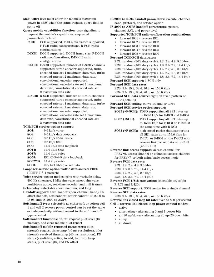
Max EIRP: user must enter the mobile’s maximum power in dBW when the status request query field is set to off
Query mobile capabilities function: uses signaling to request the mobile’s capabilities; requested parameters include:FCH: FCH supported, FCH 5 ms frames supported,
F-FCH radio configurations, R-FCH radio configurations
DCCH: DCCH supported, DCCH frame size, F-DCCH radio configurations, R-DCCH radio configurations
F-SCH: F-SCH supported, number of F-SCH channelssupported, turbo encoder supported, turbo encoded rate set 1 maximum data rate, turboencoded rate set 2 maximum data rate, convolutional encoder supported, convolutional encoded rate set 1 maximum data rate, convolutional encoded rate set 2 maximum data rate
R-SCH: R-SCH supported, number of R-SCH channels supported, turbo encoder supported, turbo encoded rate set 1 maximum data rate, turboencoded rate set 2 maximum data rate, convolutional encoder supported, convolutional encoded rate set 1 maximum data rate, convolutional encoded rate set 2 maximum data rate
TCH/FCH service option support: SO1: 9.6 kb/s voiceSO2: 9.6 kb/s data loopbackSO3: 9.6 kb/s EVRC voiceSO6: 9.6 kb/s SMSSO9: 14.4 kb/s data loopbackSO14: 14.4 kb/s SMS SO17: 14.4 kb/s voiceSO55: RC1/2/3/4/5 data loopbackSO32768: 14.4 kb/s voiceSO33: 9.6/14.4 kb/s packet data
Loopback service option traffic data source: PRBS (CCITT 215–1 pattern)
Voice service option modes: echo with variable delay, 400 Hz sinewave, 1 kHz sinewave, swept sinewave, multi-tone audio, real-time vocoder, and null frames
Echo delay: selectable short, medium, and longHandoff support: hard handoff (new channel, band), PN
offset handoff, soft handoff, softer handoff, IS-2000 toIS-95, and IS-2000 to AMPS
Soft handoff type: selectable as either soft or softer; cell1 and cell 2 reverse power control can be set the sameor independently without regard to the soft handoff type selected
Soft handoff functions: on/off, request pilot strength message, and clear mobile pilot report
Soft handoff mobile reported parameters: pilot strength request timestamp (40 ms resolution), pilot strength received timestamp (40 ms resolution), PN status (candidate, active, to add, to drop), keep status, pilot strength, and PN offset
IS-2000 to IS-95 handoff parameters: execute, channel, band, protocol, and service option
IS-2000 to AMPS handoff parameters: execute, channel, SAT, and power level
Supported TCH/FCH radio configuration combinations:• forward RC1 + reverse RC1• forward RC2 + reverse RC2• forward RC3 + reverse RC3• forward RC4 + reverse RC3• forward RC5 + reverse RC4
Forward TCH/FCH data rates:RC1: random (40% duty cycle), 1.2, 2.4, 4.8, 9.6 kb/sRC2: random (40% duty cycle), 1.8, 3.6, 7.2, 14.4 kb/sRC3: random (40% duty cycle), 1.5, 2.7, 4.8, 9.6 kb/sRC4: random (40% duty cycle), 1.5, 2.7, 4.8, 9.6 kb/sRC5: random (40% duty cycle), 1.8, 3.6, 7.2, 14.4 kb/s
Forward SCH support: 1 SCH onlyForward SCH data rates:
RC3: 9.6, 19.2, 38.4, 76.8, or 153.6 kb/sRC4: 9.6, 19.2, 38.4, 76.8, or 153.6 kb/s
Forward SCH data source: eight bit fixed pattern or PRBS (default)
Forward SCH coding: convolutional or turboForward SCH service option support:
SO32 (+F-SCH): TDSO supporting all SR1 rates up to 153.6 kb/s for F-RC3 and F-RC4
SO32 (+SCH): TDSO supporting all SR1 rates up to 153.6 kb/s for F-RC3 or F-RC4 at the same time with R-RC3
SO33 (+F-SCH): high-speed packet data supporting all SR1 rates up to 153.6 kb/s for F-RC3, or F-RC4 on the F-SCH with reverse link packet data on R-FCH (no R-SCH)
Reverse link access support: access channel for PREV=6, access channel or enhanced access channel for PREV=7, or both using basic access mode
Reverse FCH data rate:RC1: 1.2, 2.4, 4.8, 9.6 kb/sRC2: 1.8, 3.6, 7.2, 14.4 kb/sRC3: 1.5, 2.7, 4.8, 9.6 kb/sRC4: 1.8, 3.6, 7.2, 14.4 kb/s
Reverse FCH 1/8th rate gating: selectable on/off for R-RC3 and R-RC4
Reverse SCH support: SO32 assign for a single channelReverse SCH data rates:
RC3: 9.6, 19.2, 38.4, 76.8, or 153.6 kb/sReverse link closed loop bit rate: fixed to 800 per secondCell 1 reverse link closed loop power control modes:
• active• alternating – alternating 0 and 1 power bits• alt 20 up/down – alternating 20 up/20 down bits • all up • all down
11
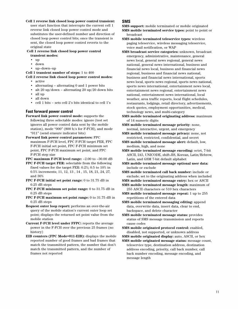
Cell 1 reverse link closed loop power control transient: user start function that interrupts the current cell 1 reverse link closed loop power control mode and substitutes the user-defined number and direction of closed loop power control bits; once the transient is sent, the closed loop power control reverts to the original state
Cell 1 reverse link closed loop power control transient modes:• up• down• up–down–up
Cell 1 transient number of steps: 1 to 400Cell 2 reverse link closed loop power control modes:
• active• alternating – alternating 0 and 1 power bits• alt 20 up/down – alternating 20 up/20 down bits • all up • all down• cell 1 bits – sets cell 2’s bits identical to cell 1’s
Fast forward power controlForward link power control mode: supports the
following three selectable modes: ignore (test set ignores all power control data sent by the mobile station), mode “000” (800 b/s for F-FCH), and mode “011” (send erasure indicator bits)
Forward link power control parameters: FPC maximum F-FCH level, FPC F-FCH target FER, FPC F-FCH initial set point, FPC F-FCH minimum set point, FPC F-FCH maximum set point, and FPC F-FCH step size
FPC maximum F-FCH level range: –2.00 to –30.00 dBFPC F-FCH target FER: selectable from the following
fixed values for the target FER: 0.2%; 0.5 to 10% in 0.5% increments; 11, 12, 13 , 14 , 15, 18, 21, 24, 27, and 30%
FPC F-FCH initial set point range: 0 to 31.75 dB in 0.25 dB steps
FPC F-FCH minimum set point range: 0 to 31.75 dB in 0.25 dB steps
FPC F-FCH maximum set point range: 0 to 31.75 dB in 0.25 dB steps
Request outer loop report: performs an over-the-air query of the mobile station’s current outer loop set point; displays the returned set point value from the mobile station
Current F-FCH level under FFPC: reports the average power in the F-FCH over the previous 25 frames (no history)
EIB counters (FPC Mode=011-EIB): displays the mobilereported number of good frames and bad frames that match the transmitted pattern, the number that don’tmatch the transmitted pattern, and the number of frames not reported
SMSSMS support: mobile terminated or mobile originatedSMS mobile terminated service types: point to point or
broadcastSMS mobile terminated teleservice types: wireless
paging teleservice, wireless messaging teleservice, voice mail notification, or WAP
SMS broadcast service categories: unknown, broadcast emergency, administrative, maintenance, general news local, general news regional, general news national, general news international, business and financial news local, business and financial news regional, business and financial news national, business and financial news international, sports news local, sports news regional, sports news national,sports news international, entertainment news local, entertainment news regional, entertainment news national, entertainment news international, local weather, area traffic reports, local flight schedules, restaurants, lodgings, retail directory, advertisements,stock quotes, employment opportunities, medical, technology news, and multi-category
SMS mobile terminated originating address: maximumof 14 numeric digits
SMS mobile terminated message priority: none, normal, interactive, urgent, and emergency
SMS mobile terminated message privacy: none, not restricted, restricted, confidential, and secret
SMS mobile terminated message alert: default, low, medium, high, and none
SMS mobile terminated message encoding: octet, 7-bit ASCII, IA5, UNICODE, shift-JIS, Korean, Latin/Hebrew,Latin, and GSM 7-bit default alphabet
SMS mobile terminated message optional user data: include or exclude
SMS mobile terminated call back number: include or exclude; set to the originating address when included
SMS mobile terminated message entry: hex or ASCIISMS mobile terminated message length: maximum of
255 ASCII characters or 510 hex charactersSMS mobile terminated message repeat: 1 up to 255
repetitions of the entered dataSMS mobile terminated messaging editing: append
data, overwrite data, insert data, clear to end, backspace, and delete character
SMS mobile terminated message status: provides status of SMS message transmission and reports cause codes
SMS mobile originated protocol control: enabled, disabled, not supported, or unknown address
SMS mobile originated display: auto, ASCII, or hexSMS mobile originated message status: message count,
teleservice type, destination address, destination address encoding, priority, call back number, call back number encoding, message encoding, and message length

12
SO33 data channelSO33 data channel operation: allows the test set to
emulate a complete data network by providing transparent connectivity to a packet data capable mobile; supports simple IP connections; requires that the test be connected to an external server via the rear panel LAN connector
SO33 dormant mode: supportedIP throughput monitor: displays a graph of the data
throughput for forward and reverse packets at the IP layer and at the RLP layer
IP throughput monitor numeric results: provides numeric results for the current, average, and peak data rates in bits per second as well as total number of bytes transferred for forward and reverse IP packets and forward and reverse OTA (over the air–RLP) packets
IP throughput monitor display axis controls: Time span: 0 to 600 s Start data rate: 0 to 600 kb/sStop data rate: 0 to 600 kb/s
IP throughput monitor trace controls: on/off function and marker function for IP Tx trace, IP Rx trace, OTA(RLP) Tx trace, and OTA (RLP) Rx trace
IP throughput monitor graph controls: clear display and freeze display
Ping function: allows the user to test network connections required for SO33 data channel capability;reports number of packets transmitted, number of packets received, percent lost, and round trip time min/avg/max
Mobile IP support: provides support for Software Concepts Inc.’s Mobile IP simulator models MIP-5800 MOB-IP-SIM or MIP-5850 MOB-IP-SIM; user control for internal simple IP support or external mobile IP support for SO33 operation; interfaces to the Mobile IP simulator through the test set’s LAN port; when in external mobile IP mode, the test set sends the data out through the LAN port in PPP over Ethernet format
Mobile IP functions:External PDSN state: on or off; when “on,” outputs PPP data via the LAN connector to the external MIP-5800 or MIP 5850 Mobile IP simulatorsExternal PDSN IP address: accepts IPv4 standard address External PDSN TCP port: 0 to 65535
Paging message error ratePaging channel MER report (PREV=6 and PREV=7
with Control Channels=PCH/ACH): provides the calculated paging channel message error rate, the mobile reported PAG_3, the number of paging messages transmitted by the test set, and the paging MER test time
Paging MER procedure control: start and stop; only available when a call is connected; “start” resets the phone’s PAG_3 value and starts the paging MER timerand counter; “stop” retrieves the mobile’s PAG_3 value and stops the Paging MER timer and counter
Paging MER calculation: computes the MER from the ratio of the mobile reported value of PAG_3 and the number of paging messages sent by the test set duringthe test interval
Audit order control: settable on/offClear paging MER procedure parameters function:
clears all of the paging MER related parametersPaging channel Eb/Nt display: displays the signal-to-
noise ratio of the paging channel when AWGN is onQuick paging channel Eb/Nt display: displays the
signal-to-noise ratio of the quick paging channel whenAWGN is on

13
F-FCH frame patternF-FCH frame pattern: selectable repeating pattern of
good, and corrupted frames with on and off controlF-FCH/Traffic good and bad frame pattern: selectable
on and off; “on” setting generates a pattern of good frames and bad (corrupted) frames
F-FCH/Traffic frame pattern good frames: selectable from 1 to 300; default setting of 3 good frames
F-FCH/Traffic frame pattern bad frames: selectable from 1 to 300; default setting of 3 bad (corrupted) frames (50% FER)
Signaling frame quality: selectable from good (ignores the F-FCH/Traffic frame pattern) or bad (follows the F-FCH/Traffic frame pattern) for outer loop report; when a reports is received, the mobile reported set point is displayed
Mobile station reported frame error rateMobile station reported frame error rate: periodic
report or threshold reportFrame interval of report: 5, 7, 10, 14, 20, 28, 40, 56, 80,
113, 160, 226, 320, 452, 640, or 905 framesFrame delay of report: 0 to 124 frames in 4 frame stepsBad frame threshold: 1 to 31 framesMobile station reported frame error rate results: MS
reported FER, MS reported bad frame, and MS reported total frames
Calling party numberCalling party number inclusion: include or excludeCalling party number: up to 20 characters consisting of
0-9, *, #, a, b, or cNumber type: unknown, international, national,
network, subscriber, and abbreviatedNumber plan: unknown, ISDN/telephony, data, telex,
and privatePresentation indicator: allowed, restricted, and number
not availableScreening indicator: user no screen, user verify pass,
user verify fail, and network
MEIDMEID functionality: user on or off controlPLCM type: ESN based, BS assigned, or MEIDQuery MEID: one button query of the mobile station for
its MEID information
CDMA authenticationFunctionality: provides basic authentication capabilities
for call processing; does not support encryptionAuthentication commands: unique challenge and SSD
updateGlobal challenge: on or offAuthentication user parameters: A-key (decimal),
RAND (hex), RANDU (hex), and RANDSSD (hex)Global challenge results: AUTHU expected value,
AUTHU received value and pass/fail result; RANDC expected value, RANDC received value and pass/fail result; COUNT (call history); AUTH_MODE
Unique challenge results: AUTHU expected value, AUTHU received value and pass/fail result
SSD update results: pass/fail result
Real-time vocoderFunctionality: provides real-time encoding of external
audio applied to the front panel audio in port and real time decoding of audio output via the front panelaudio out port
Real-time vocoder support: 13 k vocoder in service options 17 and 32768 and the EVRC vocoder in service option 3
Encoder data rate mode: auto, fixed or limited; in auto mode the vocoder algorithm selects the rate based on the sampled audio; fixed mode locks the rate to the user selected rate; limited allows the vocoder to use the user-selected rate and any lower rate, if available
Encoder data rate: full, half, quarter, or eighthExpected input voltage: 0 to 2 V; sets the input gain for
external audio applied to the front-panel audio in portMax output voltage: 0 to 5 V; sets the output level of the
decoded audio routed to the front-panel audio out portVocoder limitations: when active, no measurements are
allowed during real-time vocoding
Settable system timeFunctionality: allows user to set the system time for the
CDMA system; system time is retain during power-offusing the internal real-time clock
CDMA system date: user settable in the format of yyyy.mm.dd for the year, month, and day
CDMA system time: settable in the format of hh.mm.ss for the hour, minute, and seconds; input resolution is 2 seconds
Leap seconds: settable from 0 to 255 secondsLocal time offset: settable in the format of hh.mm from
00.00 to 15.30 in 30 minute incrementsDaylight savings time indicator: on or off
Multi-unit synchronizationFunctionality: allows any test set to be time synchronized
to another running either the E6706A or E6702B; synchronization requires one unit be designated as the time server and one as the client; the timebase and trigger outputs of the server must be connected to the client’s timebase and trigger inputs; the test sets must also be on a LAN using the same address segment
Sync to external test set: one button command to perform the synchronization
External test set LAN address: user entry of the time server’s LAN address (IPv4 address)
Synchronization fanout: maximum of four client test sets can be driven from a single timing server; unlimited number can be synchronized when they aredaisy-chained together (one unit to another)
Synchronization results: server operation complete andclient operation complete
Synchronization accuracy: typically < 1 µs

14
Hybrid modeFunctionality: supports cdma2000/1xEV-DO hybrid
mode operation when used with an E5515C running the E6706A 1xEV-DO lab application; requires that the two units are synchronized using the built-in multi-unit synchronization capability
Basic hybrid mode test capabilities: • Hybrid mode system acquisition• 1xEV-DO power save mode• Preferred control channel cycle negotiation• Dual-idle operation on CDMA and 1xEV-DO• CDMA voice call origination in dual-idle state• CDMA voice call origination in dormant 1xEV-DO
state• CDMA voice call origination in 1xEV-DO connected
state• CDMA voice call termination in dual-idle state• CDMA voice call termination in CDMA idle/1xEV-
DO dormant state• CDMA voice call termination in 1xEV-DO connected
state• SMS origination in dual-idle state• SMS origination in CDMA idle/1xEV-DO dormant
state• SMS origination in 1xEV-DO connected state• SMS termination in dual-idle state• SMS termination in CDMA idle/1xEV-DO dormant state• SMS termination in 1xEV-DO connected state• 1xEV-DO packet data call origination in dual-idle
state• 1xEV-DO packet data call re-origination in 1xEV-DO
dormant state• 1xEV-DO packet data call termination in 1xEV-DO
dormant state• CDMA packet data call when 1xEV-DO service is
unavailable Advanced hybrid mode test capabilities (requires the
use of the Software Concepts MOB-IP-SIM): • MIP call when using static home IP• MIP call when using dynamic home IP• MIP to SIP fallback if MIP call fails while trying
packet data call on 1xEV-DO• MIP to SIP fallback if MIP call fails while trying
packet data call on CDMA• Active 1xEV-DO to CDMA data session handoffs• Dormant 1xEV-DO to CDMA data session handoff• Dormant CDMA to 1xEV-DO data session handoff•1xEV-DO to CDMA to 1xEV-DO data session hand-back
Protocol logging functionalityE6702A logging functions: start protocol logging and
stop protocol loggingProtocol support: PREV=6 and PREV=7 messages;
provides correct binary output for lower PREVs, but decodes using PREV=6 messages formats
Wireless Protocol Advisor (WPA)Logging software: Agilent Wireless Protocol Advisor PC
software included with the purchase of the E6702AWPA hardware requirements: at least a Pentium® III
700 MHz PC with 128 MB of memory, 500 MB of free disc space, and a TCP/IP LAN port
WPA supported operating systems: English versions of Windows® 98, Windows NT® 4.0 (with at least service pack 4), and Windows 2000®
WPA connection: a 10 Mb/s 10 base T Ethernet connection (RJ-45 connector) using a crossover cable for direct connection to the PC or with a standard cable through a switch or hub
WPA operating modes: real-time or post captureWPA display modes: traffic overview of real-time
messages, decode view with full detail of selected message, measurement setup view for trigger, and filter configuration
Traffic overview functionalityDisplay: provides single line display of individual
protocol messages in sequential order as receivedTraffic overview configurable display columns:
message number, message direction, CDMA system time, event type, timestamp (based on PC’s real-time clock), channel type, L2 message, L3 message, and order
Measurement setup functionalityDisplay: provides a graphical block diagram of the
available test set filters, triggers, real-time filters, data log, and post-capture filters available to the user; also displays whether any triggers or filters are currently selected
Decode view functionalityDecode view displayed information types:
Test set information (indicated by blue text): CDMA system time message was sent or received with frame accuracy (20 ms), event type (PDU or duplicate PDU), and channel type
Message contents (indicated by green text): individual octet display of message or line per field display of each parameter in the message
Decode view configurable display columns:Octet number, decimal value, binary value, hex value, and field description (English)
15
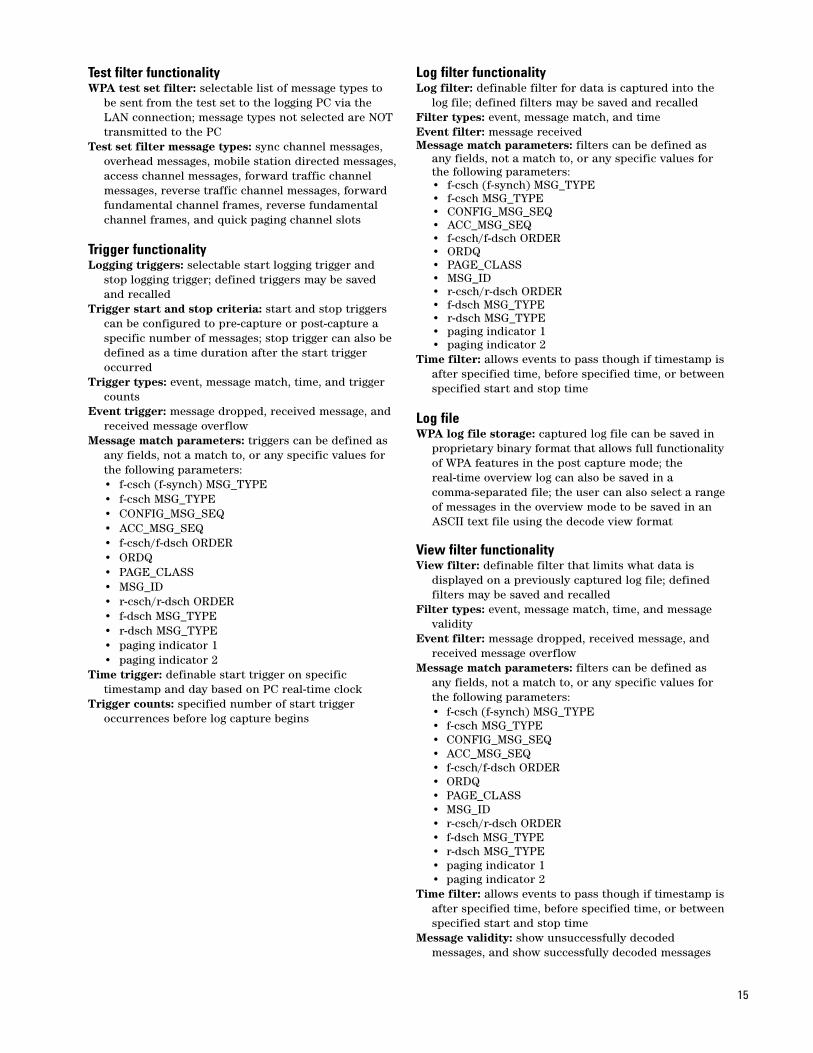
Test filter functionalityWPA test set filter: selectable list of message types to
be sent from the test set to the logging PC via the LAN connection; message types not selected are NOT transmitted to the PC
Test set filter message types: sync channel messages, overhead messages, mobile station directed messages,access channel messages, forward traffic channel messages, reverse traffic channel messages, forward fundamental channel frames, reverse fundamental channel frames, and quick paging channel slots
Trigger functionalityLogging triggers: selectable start logging trigger and
stop logging trigger; defined triggers may be saved and recalled
Trigger start and stop criteria: start and stop triggers can be configured to pre-capture or post-capture a specific number of messages; stop trigger can also be defined as a time duration after the start trigger occurred
Trigger types: event, message match, time, and trigger counts
Event trigger: message dropped, received message, and received message overflow
Message match parameters: triggers can be defined as any fields, not a match to, or any specific values for the following parameters: • f-csch (f-synch) MSG_TYPE• f-csch MSG_TYPE• CONFIG_MSG_SEQ• ACC_MSG_SEQ• f-csch/f-dsch ORDER• ORDQ• PAGE_CLASS• MSG_ID• r-csch/r-dsch ORDER• f-dsch MSG_TYPE• r-dsch MSG_TYPE• paging indicator 1• paging indicator 2
Time trigger: definable start trigger on specific timestamp and day based on PC real-time clock
Trigger counts: specified number of start trigger occurrences before log capture begins
Log filter functionalityLog filter: definable filter for data is captured into the
log file; defined filters may be saved and recalledFilter types: event, message match, and timeEvent filter: message receivedMessage match parameters: filters can be defined as
any fields, not a match to, or any specific values for the following parameters: • f-csch (f-synch) MSG_TYPE• f-csch MSG_TYPE• CONFIG_MSG_SEQ• ACC_MSG_SEQ• f-csch/f-dsch ORDER• ORDQ• PAGE_CLASS• MSG_ID• r-csch/r-dsch ORDER• f-dsch MSG_TYPE• r-dsch MSG_TYPE• paging indicator 1• paging indicator 2
Time filter: allows events to pass though if timestamp isafter specified time, before specified time, or betweenspecified start and stop time
Log fileWPA log file storage: captured log file can be saved in
proprietary binary format that allows full functionalityof WPA features in the post capture mode; thereal-time overview log can also be saved in a comma-separated file; the user can also select a rangeof messages in the overview mode to be saved in an ASCII text file using the decode view format
View filter functionalityView filter: definable filter that limits what data is
displayed on a previously captured log file; defined filters may be saved and recalled
Filter types: event, message match, time, and message validity
Event filter: message dropped, received message, and received message overflow
Message match parameters: filters can be defined as any fields, not a match to, or any specific values for the following parameters: • f-csch (f-synch) MSG_TYPE• f-csch MSG_TYPE• CONFIG_MSG_SEQ• ACC_MSG_SEQ• f-csch/f-dsch ORDER• ORDQ• PAGE_CLASS• MSG_ID• r-csch/r-dsch ORDER• f-dsch MSG_TYPE• r-dsch MSG_TYPE• paging indicator 1• paging indicator 2
Time filter: allows events to pass though if timestamp isafter specified time, before specified time, or betweenspecified start and stop time
Message validity: show unsuccessfully decoded messages, and show successfully decoded messages
16
IS-95 active cell call processing functionalityResident formats: IS-95Call processing timing tolerance: mobile transmissions
must be typically within ±6 µs of test set’s transmittedpilot channel clock timing for proper reverse channel acquisition
Cell 1 overhead channels:F-pilot: with settable PN offsetF-sync: with real-time long code and system time
update and updates for entered parameters such as SID, NID, PRAT, CDMA_FREQ, and PN OFFSET
F-paging: with real-time overhead messagesCell 2 overhead channels:
F-pilot: with settable PN offsetProtocol stack: TSB-74, J-STD-008, TIA/EIA-95-B,
ARIB T53, and Korean PCSBase station parameters: NID, SID, country code
(MCC), network code (MNC), paging rate, and CDG esc mode
Call control (“one button commands”): • register• BS call originate• BS call disconnect• MS call originate (auto answer)• MS call disconnect
Access parameters: nominal power, nominal power extended, initial power, power step number of steps, maximum request sequence, maximum response sequence, and preamble size
Threshold parameters: T_Add, T_Drop, T_Comp, T_Tdrop, Soft_Slope, Add_Intercept, and Drop_Intercept
Registration support: user-initiated (zone-based), powerup, timer-based, implicit registration (mobile originated call), or direct entry of mobile IMSI
Registration reported mobile information: ESN (hex), ESN (decimal), MCC, MNC, MSIN, slot class, slot cycleindex, protocol revision, band class, operating mode, MAX IERP, registration type, QPCH support, enhanced RC support, minimum power control step size, and MS called party number
IMSI support: class 0 onlySupported IMSI Class 0 types: MSIN only (00), MNC +
MSIN (01), MCC + MSIN (10), or MCC + MNC + MSIN (11)
IMSI page: allows making a phone call without performing a registration by entering values for the following parameters: paging type, paging MSID, paging MNC, and paging MCC
Paging type: all, MCC+MSIN, MNC+MSIN, or MSIN onlyPaging MSIN: up to 10 numeric digitsPaging MCC: 0 to 999Paging MNC: 0 to 99Paging channel data rate: selectable full or half rateStatus request query control: selectable between on
and off; default of “on” causes test set to perform the status queries during registration or mobile origination when a new ESN is received by the test set
Max EIRP: user must enter the mobile’s maximum power in dBW when the status request query field is set to off
Service option support: SO1: 9.6 kb/s voiceSO2: 9.6 kb/s data loopbackSO3: 9.6 kb/s EVRC voiceSO6: 9.6 kb/s SMSSO9: 14.4 kb/s data loopbackSO14: 14.4 kb/s SMS SO17: 14.4 kb/s voiceSO32768: 14.4 kb/s voice
Loopback service option traffic data source: PRBS (CCITT 215–1 pattern)
Traffic data rate: random (40% duty cycle), eighth, quarter, half, and full
Voice service option modes: echo with variable delay, 400 Hz sinewave, 1 kHz sinewave, swept sinewave, multi-tone audio, real-time vocoder, and null frames
Echo delay: selectable short, medium, and longHandoff support: hard handoff (new channel, band), PN
offset handoff, soft handoff, softer handoff, and IS-95 to AMPS
Soft handoff type: selectable as either soft or softer; cell1 and cell 2 reverse power control can be set the sameor independently without regard to the soft handoff type selected
Soft handoff functions: on/off, request pilot strength message, and clear mobile pilot report
Soft handoff mobile reported parameters: pilot strength message request timestamp (20 ms resolution),pilot strength message received timestamp (20 ms resolution), PN status (candidate, active, to add, to drop), keep status, pilot strength, and PN offset
CDMA to AMPS handoff parameters: execute, system type, channel, SAT, and power level
Cell 1 reverse link closed loop power control modes:• active• alternating – alternating 0 and 1 power bits• alt 20 up/down – alternating 20 up/20 down bits • all up • all down
Cell 1 reverse link closed loop power control transient: user start function that interrupts the current cell 1 reverse link closed loop power control mode and substitutes the user defined number and direction of closed loop power control bits; once the transient is sent, the closed loop power control reverts to the original state
Cell 1 reverse link closed loop power control transientmodes:• up• down• up–down–up
Cell 1 transient number of steps: 1 to 400Cell 2 reverse link closed loop power control modes:
• active• alternating – alternating 0 and 1 power bits• alt 20 up/down – alternating 20 up/20 down bits • all up • all down• cell 1 bits – sets cell 2’s bits identical to cell’s

17
SMSSMS support: mobile terminated or mobile originatedSMS mobile terminated service types: point-to-point or
broadcastSMS mobile terminated teleservice types: wireless
paging teleservice, wireless messaging teleservice, voice mail notification, or WAP
SMS broadcast service categories: unknown, broadcast emergency, administrative, maintenance, general news local, general news regional, general news national, general news international, business and financial news local, business and financial news regional, business and financial news national, business and financial news international, sports news local, sports news regional, sports news national,sports news international, entertainment news local, entertainment news regional, entertainment news national, entertainment news international, local weather, area traffic reports, local flight schedules, restaurants, lodgings, retail directory, advertisements, stock quotes, employment opportunities, medical, technology news, and multi-category
SMS mobile terminated originating address: maximumof 14 numeric digits
SMS mobile terminated message priority: none, normal, interactive, urgent, and emergency
SMS mobile terminated message privacy: none, not restricted, restricted, confidential, and secret
SMS mobile terminated message alert: default, low, medium, high, and none
SMS mobile terminated message encoding: octet, 7-bit ASCII, IA5, UNICODE, shift-JIS, Korean, Latin/Hebrew, Latin, and GSM 7-bit default alphabet
SMS mobile terminated message optional user data: include or exclude
SMS mobile terminated call back number: include or exclude; set to the originating address when included
SMS mobile terminated message entry: hex or ASCIISMS mobile terminated message length: maximum of
255 ASCII characters or 510 hex charactersSMS mobile terminated message repeat: 1 up to 255
repetitions of the entered dataSMS mobile terminated messaging editing: append
data, overwrite data, insert data, clear to end, backspace, and delete character
SMS mobile terminated message status: provides status of SMS message transmission and reports cause codes
SMS mobile originated protocol control: enabled, disabled, not supported, or unknown address
SMS mobile originated display: auto, ASCII, or hexSMS mobile originated message status: message count,
teleservice type, destination address, destination address encoding, priority, call back number, call back number encoding, message encoding, and message length
Paging channel data rate: selectable full or half ratePaging channel MER report: provides the calculated
paging channel message error rate, the mobile reportedPAG_3, the number of paging messages transmitted by the test set, and the paging MER test time
Paging message error ratePaging MER procedure control: start and stop; only
available when a call is connected; “start” resets the phone’s PAG_3 value and starts the paging MER timerand counter; “stop” retrieves the mobile’s PAG_3 value and stops the Paging MER timer and counter
Paging MER calculation: computes the MER from the ratio of the mobile reported value of PAG_3 and the number of paging messages sent by the test set during the test interval
Audit order control: settable on/offClear paging MER procedure parameters function:
clears all of the paging MER-related parametersPaging channel Eb/Nt display: displays the signal-to-
noise ratio of the paging channel when AWGN is on
F-FCH frame patternF-FCH frame pattern: selectable repeating pattern of
good and corrupted frames with on and off controlF-FCH/Traffic good and bad frame pattern: selectable
on and off; “on” setting generates a pattern of good frames and bad (corrupted) frames
F-FCH/Traffic frame pattern good frames: selectable from 1 to 300; default setting of 3 good frames
F-FCH/Traffic frame pattern bad frames: selectable from 1 to 300; default setting of 3 bad (corrupted) frames (50% FER)
Signaling frame quality: selectable from good (ignores the F-FCH/Traffic frame) pattern, or bad (follows the F-FCH/Traffic frame pattern) for outer loop report; when a reports is received, the mobile reported set point is displayed

18
Mobile station reported frame error rateMobile station reported frame error rate: periodic
report or threshold reportFrame interval of report: 5, 7, 10, 14, 20, 28, 40, 56, 80,
113, 160, 226, 320, 452, 640, or 905 framesFrame delay of report: 0 to 124 frames in 4 frame stepsBad frame threshold: 1 to 31 framesMobile station reported frame error rate results: MS
reported FER, MS reported bad frame, and MS reported total frames
Calling party numberCalling party number inclusion: include or excludeCalling party number: up to 20 characters consisting of
0-9, *, #, a, b, or cNumber type: unknown, international, national,
network, subscriber, or abbreviatedNumber plan: unknown, ISDN/telephony, data, telex, or
privatePresentation indicator: allowed, restricted, or number
not availableScreening indicator: user no screen, user verify pass,
user verify fail, and network
CDMA authenticationFunctionality: provides basic authentication capabilities
for call processing; does not support encryptionAuthentication commands: unique challenge and SSD
updateGlobal challenge: on or offAuthentication user parameters: A-key (decimal),
RAND (hex), RANDU (hex), and RANDSSD (hex)Global challenge results: AUTHU expected value,
AUTHU received value and pass/fail result; RANDC expected value, RANDC received value and pass/fail result; COUNT (call history); AUTH_MODE
Unique challenge results: AUTHU expected value, AUTHU received value and pass/fail result
SSD update results: pass/fail result
Real-time vocoderFunctionality: provides real-time encoding of external
audio applied to the front panel audio in port and real time decoding of audio output via the front panelaudio out port
Real-time vocoder support: 13 k vocoder in service options 17 and 32768 and the EVRC vocoder in service option 3
Encoder data rate mode: auto, fixed or limited; in auto mode the vocoder algorithm selects the rate based on the sampled audio; fixed mode locks the rate to the user selected rate; limited allows the vocoder to use the user selected rate and any lower rate, if available
Encoder data rate: full, half, quarter, or eighthExpected input voltage: 0 to 2 V; sets the input gain forexternal audio applied to the front-panel audio in portMax output voltage: 0 to 5 V; sets the output level of the
decoded audio routed to the front-panel audio out portVocoder limitations: when active, no measurements are
allowed during real-time vocoding
Settable system timeFunctionality: allows user to set the system time for the
CDMA system; system time is retain during power-offusing the internal real-time clock
CDMA system date: settable in the format of yyyy.mm.dd for the year, month, and day
CDMA system time: settable in the format of hh.mm.ss for the hour, minute, and seconds; input resolution is 2 seconds
Leap seconds: settable from 0 to 255 secondsLocal time offset: settable in the format of hh.mm from
00.00 to 15.30 in 30 minute incrementsDaylight savings time indicator: on or off
Multi-unit synchronizationFunctionality: allows any test set to be time synchronized
to another running either the E6706A or E6702B; synchronization requires one unit be designated as the time server and one as the client; the timebase and trigger outputs of the server must be connected to the client’s timebase and trigger inputs; the test sets must also be on a LAN using the same address segment
Sync to external test set: one button command to perform the synchronization
External test set LAN address: user entry of the time server’s LAN address (IPv4 address)
Synchronization fanout: maximum of four client test sets can be driven from a single timing server; unlimited number can be synchronized when they aredaisy-chained together (one unit to another)
Synchronization results: server operation complete andclient operation complete
Synchronization accuracy: typically < 1 µs
19
IS-2000 test mode functionalityResident formats: IS-2000 SR1Control channel configuration: PCH/ACH or
BCCH/CCCH/EACHCell 1 overhead channels (Control channels=PCH/ACH):
F-Pilot: with settable PN offsetF-Sync: with real-time long code and system time
update and updates for user entered parameters
F-Paging: with real-time overhead messagesF-QPCH: indicates if active page will be in the next
paging channel slotCell 1 overhead channels (Control channels=BCCH/
CCCH/EACH):F-Pilot: with user settable PN offsetF-Sync: with real-time long code and system time
update and updates for user entered parameters
F-BCCH: with real-time overhead messagesF-CCCH: with real-time signaling messagesF-QPCH: indicates if active page will be in the next
paging channel slotCell 2 overhead channels:
F-Pilot: with settable PN offsetCell 1 overhead messages (Control channels=
PCH/ACH): system parameters message, channel list message, access parameters message, extended system parameters message, and extended neighbor list message
Cell 1 overhead messages (Control channels= BCCH/CCCH/EACH): ANSI-41 system parameters message, MM-RC parameters message, extended channel list message, enhanced access parameters message, and universal neighbor list message
F-BCCH rate (Control channels=BCCH/CCCH/EACH):4.8 kb/s (1/2 rate coding, 160 ms slot), 9.6 kb/s (1/2 rate coding, 80 ms slot), or 19.2 kb/s (1/2 rate coding, 40 ms slot)
F-CCCH rate (Control channels=BCCH/CCCH/EACH):9.6 kb/s (1/4 rate coding, 20 ms frame), 9.6 kb/s (1/2 rate coding, 20 ms frame), and 19.2 kb/s (1/2 rate coding, 20 ms frame)
F-QPCH data rate: selectable from either full or half rateBase station parameters: NID, SID, country code (MCC),
network code (MNC), paging rate, CDG esc mode, F-QPCH state, F-QPCH relative level, F-QPCH data bits (all on or all off), and reverse link traffic pilot gain
Call control ("one button commands"): noneAccess parameters: noneRegistration support: noneService option support: noneHandoff support: noneR-Access channel: not supportedChip rate: 1.2288 Mc/sSupported radio configuration combinations:
• forward RC1 + reverse RC1• forward RC2 + reverse RC2• forward RC3 + reverse RC3• forward RC4 + reverse RC3• forward RC5 + reverse RC4
Channel coding: convolutional or turbo on all rates withthe exception that turbo coding is not available on RC3 at 9.6 kb/s, RC4 at 9.6kb/s, or RC5 at 14.4 kb/s per IS-2000
Traffic data source: PRBS (CCITT 215–1 pattern)Forward FCH data rate:
RC1: random (40% duty cycle), 1.2, 2.4, 4.8, 9.6 kb/sRC2: random (40% duty cycle), 1.8, 3.6, 7.2, 14.4 kb/sRC3: random (40% duty cycle), 1.5, 2.7, 4.8, 9.6 kb/sRC4: random (40% duty cycle), 1.5, 2.7, 4.8, 9.6 kb/sRC5: random (40% duty cycle), 1.8, 3.6, 7.2, 14.4 kb/s
Forward SCH support: one supplemental channelF-SCH data rate:
RC3: 9.6, 19.2, 38.4, 76.8, or 153.6 kb/sRC4: 9.6, 19.2, 38.4, 76.8, or 153.6 kb/sRC5: 14.4, 28.8, 57.6, 115.2, or 230.4 kb/s
Power control groups: 16 per frameReverse link closed loop support: transmits bits only
(no reverse link demodulation)Reverse link closed loop bit rate: fixed to 800 per
second
20
Cell 1 reverse link closed loop power control modes:• alternating – alternating 0 and 1 power bits• alt 20 up/down – alternating 20 up/20 down bits • all up • all down
Cell 1 reverse link closed loop power control transient: user start function that interrupts the current cell 1 reverse link closed loop power control mode and substitutes the user defined number and direction of closed loop power control bits; once the transient is sent, the closed loop power control reverts to the original state
Cell 1 reverse link closed loop power control transientmodes:• up• down• up–down–up
Cell 1 transient number of steps: 1 to 400Cell 2 reverse link closed loop power control modes:
• alternating – alternating 0 and 1 power bits• alt 20 up/down – alternating 20 up/20 down bits • all up • all down• cell 1 bits – sets cell 2’s bits identical to cell 1’s
Forward link power support: noneMobile station identification: user entry of ESN (hex);
entry of all “F” hex data results in using a zero long code mask on the source
F-FCH frame patternF-FCH frame pattern: selectable repeating pattern of
good and corrupted frames with on and off controlF-FCH/Traffic good and bad frame pattern: selectable
on and off; “on” setting generates a pattern of good frames and bad (corrupted) frames
F-FCH/Traffic frame pattern good frames: selectable from 1 to 300; default setting of 3 good frames
F-FCH/Traffic frame pattern bad frames: selectable from 1 to 300; default setting of 3 bad (corrupted) frames (50% FER)
Signaling frame quality: selectable from good (ignores the F-FCH/Traffic frame pattern) or bad (follows the F-FCH/Traffic frame pattern) for outer loop report; when a reports is received, the mobile reported set point is displayed
CDMA RF generatorChannelsAdditive white Gaussian noise source: yesAWGN bandwidth: typically 1.8 MHz < BW < 2.1 MHzCDMA channels:CDMA cell 1 code channels (PREV<=6):
F-pilot: fixed at Walsh code 0F-sync: fixed at Walsh code 32F-paging: fixed at Walsh code 1 F-QPCH: (IS-2000 only) fixed at Walsh code 80F-FCH: selectable Walsh code from
the following set: 10, 14, 26, 30, 42, 46, 58, or 62
F-SCH: (IS-2000 only) fixed to Walsh code 3F-OCNS: selectable Walsh code from
the following set: 5, 13, 21, 29, 37, 45, 53, and 61
CDMA cell 1 PN offset: selectable from 0 to 511CDMA cell 2 consisting of these code channels:
F-pilot: fixed at Walsh code 0F-FCH: selectable Walsh code from
the following set: 10, 14, 26, 30, 42, 46, 58, or 62
F-OCNS: selectable Walsh code from the following set: 5, 13, 21, 29, 37, 45, 53, and 61
CDMA cell 2 PN offset: selectable from 0 to 511
FrequencyFrequency range:• US cellular band (860.04-893.97 MHz, channels 1-799,
991-1023, 1024-1323)• Japan CDMA band (approx. 832-869.9875 MHz,
channels 1-799, 801-1039, 1041-1199, 1201-1600)• US PCS band (1930-1990 MHz, channels 1-1199)• Korean PCS band (1840-1870 MHz, channels 0-599)• NMT- 450 band (approx. 421-494 MHz, channels
1-300, 539-871, 1039-1473, 1792-2016)• IMT- 2000 band (2110-2169.950 MHz, channels
0-1199)• Secondary 800 MHz band (approx. 851-869 MHz, and
935-940 MHz, channels 0-719, 720-919)Frequency setting: by channel number or MHz (IS-2000
test mode only)Frequency setting resolution: typically 1 Hz
21
F-pilot relative level: –20 to 0 dB, or offF-sync relative level: –20 to 0 dB, or offF-paging relative level (PREV<=6): –20 to 0 dB, or offF-FCH channel relative level: settable from –30 to 0 dB
with 0.01 dB resolution, or offF-SCH channel relative level: settable from –20 to 0 dB
with 0.01 dB resolution, or offAWGN channel relative level range: settable to ±15 dB
relative to the set CDMA cell power with 0.01 dB resolution
F-OCNS Walsh code length: fixed to 64 bitsF-OCNS relative level range: automatically calculated
from other code channel relative levels to provide the set CDMA cell power (range of –30 to 0 dB, or off)
Relative CDMA channel level accuracy: typically < ±0.2 dB
Cell 2 delay: settable timing delay of cell 2 signal relative to cell 1 timing in 0.813 µs (1 chip) intervals from 0.0 to –13.02 µs (0 to 15 chips)
CDMA modulationModulation type: parallel BPSK for IS-95 channels and
IS-2000 pilot, sync, and paging channels and complex QPSK for the F-FCH per IS-2000
Modulation quality: IS-95, RC1, and RC2 residual rho: > 0.98, typically > 0.995RC3, RC4, and RC5 residual rho (pilot only): > 0.98, typically > 0.995
Residual EVM: < 10%, typically < 3.1%Carrier feedthrough: < –25 dBc, typically –40 dBc
CDMA RF analyzer (measurements only)Frequency range (reverse channels): US cellular band: 1-799, 991-1023, 1024-1323US PCS band: 1-1199Korean PCS band: 0-599Japan CDMA band: 1-799, 801-1039, 1041-1199,
1201-1600IMT-2000 band: 0-1199NMT-450 band: 1-300, 539-871, 1039-1473,
1792-2016Secondary 800 band: 0-719, 720-919Maximum input level: +37 dBm peak (5 W peak)Input level range: –71 to +30 dBm/1.23 MHzReceiver ranging:
Auto mode: Autoranges to the ideal RF power level for the nominally expected open loop response; provides calibrated results if actual received power is within ±9 dB of the expected open loop powerManual mode: user enters expected power; if the “active" mode is selected, the test set uses closed looppower control to drive the mobile to the expected power, otherwise, the mobile’s Tx power must be within ±9 dB of the expected power to provide calibrated results
AmplitudeOutput port control: user control of RF source routing
to either the RF in/out port or the RF out only portRF in/out composite signal level: sum of the set values
of the CDMA cell 1 power, CDMA cell 2 power, and the AWGN source power
RF in/out CDMA cell 1 output level range (AWGN off):–120 dBm/1.23 MHz to –13 dBm/1.23 MHz
RF in/out CDMA cell 2 output level range (AWGN off):–120 dBm/1.23 MHz to –13 dBm/1.23 MHz
RF in/out AWGN output level range:–120 dBm/1.23 MHz to –20 dBm/1.23 MHz; over-range available with reduced performance to –15 dBm/1.23 MHz
RF in/out CDMA cell absolute output level accuracy (AWGN off):< ±1.1 dB, –109 to –15 dBm/1.23 MHz,typically ±0.62 dB, –109 to –15 dBm/1.23 MHz
RF in/out composite absolute output level accuracy (AWGN on):< ±1.2 dB, –109 to –20 dBm/1.23 MHz, typically ±0.7 dB, –109 to –20 dBm/1.23 MHz
RF in/out reverse power: +37 dBm peak (5 W peak)RF in/out VSWR: < 1.14:1, 400 to 1000 MHz,
< 1.2:1, 1700 to 2000 MHz,< 1.32:1, 2010 to 2180 MHz
RF out only composite signal level: sum of the set values of the CDMA cell 1 power, CDMA cell 2 power, and the AWGN source power
RF out only CDMA cell 1 output level range (AWGN off):–115 dBm/1.23 MHz to –5 dBm/1.23 MHz
RF out only CDMA cell 2 output level range (AWGN off):–115 dBm/1.23 MHz to –5 dBm/1.23 MHz
RF out only AWGN output level range:–115 dBm/1.23 MHz to –12 dBm/1.23 MHz;over-range available with reduced performance to –7 dBm/1.23 MHz
RF out only CDMA cell absolute output level accuracy (AWGN off):< ±1.1 dB, –109 to –7 dBm/1.23 MHz, typically < ±0.62 dB, –109 to –7 dBm/1.23 MHz
RF out only composite absolute output level accuracy (AWGN on):< ±1.2 dB, –109 to –12 dBm/1.23 MHz,typically < ±0.7 dB, –109 to –12 dBm/1.23 MHz
RF out only reverse power: +24 dBm peak (250 mW peak)RF out only VSWR: typically < 1.3:1 for 400 to 500 MHz,
< 1.4:1 for 800 to 1000 MHz, and < 1.45:1 for 1.7 to 2.2 GHz
Isolation (from RF out only port to RF in/out when the RF source is routed to the RF out only port): typically > 40 dB

22
CDMA analyzer
Average power measurementInput frequency ranges:
• 411 to 484 MHz• 800 to 1000 MHz• 1700 to 2000 MHz
Detector types:Peak detector: in IS-95, R-RC1, and R-RC2 modesThermal detector: in R-RC3 and R-RC4 modes
Maximum input level: +37 dBm peak (5 W peak)Measurement range: –10 to +30 dBm; usable from –10
to –20 dBm with reduced accuracy (peak detector only)
Measurement level ranging: autoMeasurement data capture period: 10 ms Measurement result: average powerConcurrency support: average power measurements can
be made concurrently with all CDMA measurements that support concurrency
Peak detector measurement accuracy (20 to 55 °C, after calibration, IS-95 or reverse RC1, RC2): –10 to +30 dBm:• 400 to 500 MHz: < ±7.3%, typically < ±3.0%• 800 to 1000 MHz: < ±7.0%, typically <±3.0%• 1700 to 2000 MHz: < ±7.4%, < ±8.3% when the RF
Out Only port is selected, typically < ±4.4%–10 to –20 dBm:• 400 to 500 MHz: typically < ±4.4%• 800 to 1000 MHz: typically < ±4.2%• 1700 to 2000 MHz: typically < ±4.8%, < ±5.6% when
the RF Out Only port is selectedThermal detector measurement accuracy (accuracy
with 10 internal averages; reverse RC3 or RC4): –10 to +30 dBm:• 400 to 500 MHz: < ±6.6%, typically < ±3.0%• 800 to 1000 MHz: < ±6.0%, typically < ±3.0%• 1700 to 2000 MHz: < ±7.2%, < ±8.2% when the RF
Out only port is selected, typically < ±3.3%Measurement repeatability: typically < ±0.05 dBMeasurement resolution: 0.01 dBmZero function: auto zeroes (no user control)
Tuned channel power measurementInput frequency ranges:
• 411 to 420 MHz• 450 to 484 MHz• 824 to 934 MHz• 1750 to 1780 MHz• 1850 to 1980 MHz
Measurement method: measures the total power in a 1.23 MHz bandwidth centered on the active reverse channel center frequency
Measurement data capture period: 0.3125 ms (very fastmode), 1.25 ms (fast mode,) or 10 ms (normal mode)
Measurement trigger: 20 ms clock (frame trigger)Maximum input level: +37 dBm/1.23 MHz peak (5 W
peak)Measurement range: –61 to +30 dBm, useable to
< –69 dBm/1.23 MHz with reduced accuracyMeasurement level ranging: auto and manualMeasurement accuracy: calibrated against average
power and within ±10 degrees of calibration temperature; calibration must occur between 20 to 55 °C): < ±1 dB 15 to 55 °C, typically < ±0.5 dB
Measurement resolution: 0.01 dBm/1.23 MHzMeasurement result: channel power in a 1.23 MHz
bandwidthConcurrency capabilities: channel power measurements
can be made concurrently with all CDMA measurements that support concurrency
Calibrate function: calibrates the channel power measurement over the entire operating frequency range of the test set against the average power measurement; no external cabling is required
Calibration time: typically < 120 s
Access probe power measurementInput frequency ranges:
• 411 to 420 MHz• 450 to 484 MHz• 824 to 934 MHz• 1750 to 1780 MHz• 1850 to 1980 MHz
Measurement method: measures the total power in a 1.23 MHz bandwidth centered on the active reverse channel center frequency
Measurement data capture period: 2.5 msMeasurement trigger: amplitude rise onlyMaximum input level: +37 dBm/1.23 MHz peak (5 W
peak)Measurement range: –54 to +30 dBmMeasurement level ranging: auto and manualMeasurement accuracy: calibrated against average
power and within ±10 degrees of calibration temperature; calibration must occur between 20 to 55 °C: < ±1 dB 15 to 55 °C, typically < ±0.5 dB
Measurement result: access probe power in a 1.23 MHz bandwidth
Concurrency capabilities: none

Graphical access probe power measurementInput frequency ranges:
• 411 to 420 MHz• 450 to 484 MHz• 824 to 934 MHz• 1750 to 1780 MHz• 1850 to 1980 MHz
Measurement method: measures the total power in a 1.23 MHz bandwidth centered on the active reverse channel center frequency
Measurement data capture period: 2.5 msMeasurement trigger: amplitude rise onlyMaximum input level: +37 dBm/1.23 MHz peak (5 W
peak)Measurement range: –54 to +30 dBmMeasurement level ranging: auto and manual; in auto
mode, the test set ranges based on the set values of the parameters: power step, number of steps, and maximum response sequence
Measurement dynamic range: in auto ranging mode, typically provides accurate measurement results foraccess probes < +15 dB above the initial mobile expected power (open loop estimate)
Measurement accuracy: calibrated against average power and within ±10 degrees of calibration temperature; calibration must occur between 20 to 55 °C: < ±1 dB 15 to 55 °C, typically < ±0.5 dB
Measurement results: provides a bar graph for up to 20 captured probes and a result table that reports absolute power in each probe and the power delta from the previous access probe; access probe power is reported in a 1.23 MHz bandwidth
Concurrency capabilities: none – selecting graphical access probe power closes all other active measurements
Handoff modulation quality measurementInput frequency ranges:
• 411 to 484 MHz• 800 to 1000 MHz• 1700 to 2000 MHz
Measurement chip rate: 1.2288 Mc/sModulation measurement method: PN offset handoff
for IS-2000 R-RC3 or R-RC4 to generate reverse pilot only preamble; measures single code rho on the preamble with HPSK (R-Pilot only); performs two handoffs: one to initiate the preamble and a second to return to the initial PN offset
Maximum input level: +37 dBm/1.23 MHz peak (5 W peak)
Input level range: –25 to +30 dBm/1.23 MHz, usable to –50 dBm/1.23 MHz with reduced accuracy
Modulation quality measurement range: 0.40 to 1.00 rho (for signals with < ±6 µs time error and < ±1 kHz frequency error)
Measurement interval: 1.042 ms (5 Walsh symbols)Modulation quality measurement accuracy:
< ±0.003 + residual error for 0.8 < rho < 1.0Modulation quality measurement residuals:
Residual rho: > 0.999Residual EVM: < 4% rmsResidual time error: ±0.11 µsFrequency error: ±15 Hz plus timebase error
Measurement results: rho, frequency error, time error, carrier feedthrough, phase error, amplitude error, and EVM
Concurrency capabilities: none
23
Modulation quality measurementInput frequency ranges:
• 411 to 484 MHz • 800 to 1000 MHz• 1700 to 2000 MHz
Measurement chip rate: 1.2288 Mc/sModulation measurement method:
IS-95, RC1, or RC2: single code rhoRC3, RC4, or RC5: multi-code rho and EVM with code domain results
Maximum input level: +37 dBm/1.23 MHz peak (5 W peak)
Input level range: –25 to +30 dBm/1.23 MHz, usable to –50 dBm/1.23 MHz with reduced accuracy
Modulation quality measurement range (for signals with < ±6 µs time error and < ±1 kHz frequency error):IS-95, RC1, or RC2: 0.40 to 1.00 rhoRC3, RC4, or RC5: 1 to 40% EVM
Measurement interval: 1.042 ms (5 Walsh symbols)Modulation quality measurement accuracy:
IS-95, RC1, or RC2 rho: < ±0.003 + residual error for 0.8 < rho < 1.0RC3, RC4, or RC5 EVM: < ±1.25% rms + residual error for 1% < EVM < 20%
Modulation quality measurement residuals: Residual rho: > 0.999Residual EVM: < 4% rms, typically < 3.1% rmsResidual time error: ±0.11 µsFrequency error: ±15 Hz plus timebase errorResidual code domain power: < –35 dBc
Code domain power relative measurement accuracy (IS-2000 R-RC3 and R-RC4 only): < ±0.005 relative tototal power for linear code domain powers from 0.05 to 1.0
Code domain power offset relative to reversepilot channel (IS-2000 R-RC3 and R-RC4 only):< ±0.20 dB
Code domain results (IS-2000 R-RC3 and R-RC4 only):Code domain power graph: displays the power in all 16 Walsh coded channels (16 bit) for both the I channel and the Q channel; reported power in each graph is relative to the total combined I and Q channel power; red bars indicate active channels, while yellow bars indicate inactive channelsCode domain table: displays the Walsh code, spread factor, code domain power (at SF=16), total code domain power, and code power relative to the R-Pilot channel for each active reverse channel; possible active channels per IS-2000 include the R-Pilot, R-FCH, R-DCCH, R-SCH1 and R-SCH2Code domain power and noise graph: displays the power and noise in all 16 Walsh coded channels (16 bit) for both the I channel and the Q channel; reported power in each graph is relative to the total combined I and Q channel power; red bars indicate active channels, while yellow bars indicate noise in each channel
Code domain measurement results: pass/fail indicationbased on IS-98E standard specifications
Modulation quality measurement results: rho, frequencyerror, time error, carrier feedthrough, phase error, amplitude error, and EVM
Statistical measurement results: provides minimum, maximum, and average for rho, frequency error, time error, carrier feedthrough, phase error, amplitude error, and EVM when multi-measurement mode is active; no statistical results are available for any of the code domain power results
Concurrency capabilities: modulation quality measurements can be made concurrently with all CDMA measurements that support concurrency
24

Code channel time and phase error measurementInput frequency ranges:
• 411 to 484 MHz • 800 to 1000 MHz• 1700 to 2000 MHz
Measurement chip rate: 1.2288 Mc/sMeasurement method (IS-2000 R-RC3 and R-RC4
only): measures all active reverse code channel’s timeand phase error relative to the mobile’s transmitted R-pilot channel
Maximum input level: +37 dBm/1.23 MHz peak (5 W peak)
Input level range: –25 to +30 dBm/1.23 MHz, usable to –50 dBm/1.23 MHz with reduced accuracy
Code channel time and phase error measurement range (for signals with < ±6 µs static time error and < ±1 kHz frequency error):Code channel time error: up to ±100 nsCode channel phase error: up to ±0.5 radians
Measurement interval: 1.042 ms (5 Walsh symbols)Relative code channel measurement accuracy:
these tables display the accuracy versus the residual EVM of the phone for a given number of measurement averages; these graphs are valid for all reverse channel configurations where each active channel hasat least 10 percent of the total power:
Measurement residuals: Code channel residual time error: ±3 ns, typically ±16 ns at –50 dBm/1.23 MHzCode channel residual phase error: ±7 milli-radians,
typically ±26 milli-radians at –50 dBm/1.23 MHzGraphical results:
Code channel time error graph: displays the relativetime error in all 15 Walsh coded channels (16 bit) for both the I channel and the Q channel relative to the R-Pilot channel; red bars indicate time error ineach detected active channelCode channel phase error graph: displays the relative phase error in all 15 Walsh coded channels (16 bit) for both the I channel and the Q channelrelative to the R-Pilot channel; red bars indicate phase error in each detected active channel
Concurrency capabilities: code channel time and phase error measurements can be made concurrently with all CDMA measurements that support concurrency
Pass/fail limits: settable with default value set to the IS-98D limits of ±10 ns for code channel time error and ±0.15 radians for code channel phase error
Other measurement results: pass/fail for each graph
25
Timing error accuracy
0.00
2.00
4.00
6.00
8.00
10.00
12.00
14.00
16.00
18.00
1.00% 2.00% 5.00% 10.00% 20.00% 30.00% 40.00%
Phone EVM
Tim
ing
erro
r (n
s) 1 average
2 averages
5 averages
10 averages
20 averages
50 averages
100 averages
Phase error accuracy
0.00
5.00
10.00
15.00
20.00
25.00
30.00
35.00
1.00% 2.00% 5.00% 10.00% 20.00% 30.00% 40.00%
Phone EVM
Phas
e er
ror
(mra
d)
1 average
2 averages
5 averages
10 averages
20 averages
50 averages
100 averages
Time response of open loop power control measurementInput frequency ranges:
• 411 to 420 MHz• 450 to 484 MHz • 824 to 934 MHz• 1750 to 1780 MHz• 1850 to 1980 MHz
Measurement method: measures the open loop power versus time response of a mobile to a 20 dB step in the test set’s cell power
Measurement data capture period: 100 msMeasurement trigger: user-initiatedMaximum input level: +37 dBm/1.23 MHz peak (5 W
peak)Measurement range: –46 to +30 dBm (final level after
±20 dB step in cell power)Measurement level ranging: autoMeasurement cell power step size: +20, –20 dBMarker relative level accuracy: ±0.5 dBMarker time accuracy: ±540 µsMeasurement limits: time versus amplitude mask per
IS-98DGraphical results:
Graph: single trace with IS-98D standard limit linesTime display resolution: 270 µsTime display range: 0 to +100 msAmplitude range: –5 to +30 dB
Available results: pass or fail result and trace of 371 data points available via GPIB
Concurrency capabilities: none; selecting this measurement automatically closes all other active measurements
Tx spurious emissionsInput frequency ranges:
• 411 to 420 MHz• 450 to 484 MHz • 824 to 934 MHz• 1750 to 1780 MHz• 1850 to 1980 MHz
Measurement method: measures the active carrier power in a 1.23 MHz bandwidth, then measures the power in a 30 kHz bandwidth at two offsets above and below the active carrier and displays the ratio of the offset powers to the active carrier power in dBc; measurement returns valid results for full rate only inR-RC1 or R-RC2; all rates are support in R-RC3 and R-RC4
Measurement data capture period: 5 msMeasurement offsets:
Frequencies < 1000 MHz: ±885 kHz, ±1.98 MHzFrequencies > 1000 MHz: ±1.25 MHz, ±1.98 MHz
Measurement bandwidth:Active carrier: 1.23 MHzOffsets: 30 kHz synchronously tuned, five pole filter with approximately Gaussian shape
Measurement trigger: 20 ms frame clockMaximum input level: +37 dBm/1.23 MHz peak (5 W
peak)Measurement range: 0 to +30 dBmMeasurement level ranging: autoMarker relative level accuracy:
±885 kHz, ±1.25 MHz offsets: < ±0.4 dB,typically < ±0.2 dB±1.98 MHz offsets: < ±0.8 dB, typically < ±0.5 dB
Measurement residual relative power: ±885 kHz, ±1.25 MHz offsets: < –62 dBc/30 kHz BW±1.98 MHz offsets: < –66 dBc/30 kHz BW
Mobile pass/fail limits (per IS-98D): Auto mode:
Frequencies < 1000 MHz:• –42 dBc/30 kHz for ±885 kHz offsets • –54 dBc/30 kHz for ±1.98 MHz offsetsFrequencies > 1000 MHz:• –42 dBc/30 kHz for ±1.25 MHz offsets• –50 dBc/30 kHz for ±1.98 MHz offsets
Manual mode: settable from –10 to –65 dBc with 0.01 dB resolution
Numeric results: relative power in dBc/30 kHz for each of the four offset frequencies
Graphical results: Graph: single trace with IS-98D standard limit lines and one bar representing the channel power and four bars representing the relative power at the four offsetfrequenciesAmplitude range: 0 to –80 dB
Concurrency capabilities: Tx spurious emissions measurements can be made concurrently with all CDMA measurements that support concurrency
26

Gated power measurementInput frequency ranges:
• 411 to 420 MHz• 450 to 484 MHz • 824 to 934 MHz• 1750 to 1780 MHz• 1850 to 1980 MHz
Measurement method: displays the time domain pulse of an IS-95, RC1, or RC2, 1/8th rate frame
Measurement data capture period: 1.277 msMeasurement trigger: 20 ms clock (frame trigger)Maximum input level: +37 dBm/1.23 MHz peak (5 W
peak)Measurement input level range: –20 to +30 dBmMeasurement averaging: default of 100, selectableMarker relative level accuracy (averages > 25):
+5 to –22 dB: < ±0.4 dB + 0.1 dB for signal fall times less than 2 µs, typically < ±0.30 dB–22 to –25 dB: < ±0.7 dB + 0.2 dB for signal fall timesless than 2 µs, typically < ±0.55 dB
Marker level resolution: 0.01 dBMeasurement limits: time domain mask per IS-98DGraphical results: zoom view
Full trace: displays a time window of 1277 µs centered on the burst; grey bar indicates which section of the full trace appears in the zoomed trace
Time display range: –15 to +1262 µsLevel display range: –35 to +5 dB
Zoom position: 0 to 13Zoomed trace: displays a zoomed section of the full
graphZoomed time display resolution:
zoom views 0, 13: 68 nszoom views 1 to 12: 276 ns
Time display range: zoom view 0: –15.06 to +10.04 µszoom view 1: +10.21 to +112.21 µszoom view 2: +112.47 to +214.47 µszoom view 3: +214.74 to +316.74 µszoom view 4: +317.00 to +419.01 µszoom view 5: +419.28 to +521.27 µszoom view 6: +521.55 to +623.54 µszoom view 7: +623.81 to +725.54 µszoom view 8: +725.81 to +827.81 µszoom view 9: +828.08 to +930.07 µszoom view 10: +930.35 to +1032.34 µszoom view 11: +1032.61 to +1134.61 µszoom view 12: +1134.88 to +1236.88 µszoom view 13: +1237.05 to +1262.14 µs
Level display range: –35 to +5 dBGraphical results: rise/fall view
Rise trace:Time display range: –15 to +1262 µsTime display resolution: 68 nsLevel display range: –35 to +5 dB
Fall trace:Time display range: –15 to +1262 µsTime display resolution: 68 nsLevel display range: –35 to +5 dB
Other measurement results: pass/fail indicator, first fail point time and level, and mask shift (indicates the time shift required to center IS-98D mask on the burst); full trace is available via GPIB
Concurrency capabilities: none
Frame error rate measurementFER measurement method: data loopback in service
options 002, 009, and 055 with confidence limitsFER input level measurement range: –65 dBm/
1.23 MHz to +30 dBm/1.23 MHzFER measurement residual error rate: < 1 x 10⁻⁶ for
inputs levels in the specified input level range and within ±9 dB of the expected input power
Confidence limit range: definable from 80.0 to 99.9% and off
FER requirement range: definable from 80.0 to 99.9% and off
Eb/Nt limit range (FPC on): definable from –30.00 to +42.00 dB; used for pass/fail criteria when using fast forward power control
Minimum frame count: definable number of frames to test before confidence limit checking is started; must be set properly to obtain accurate test results when fading is enabled and if confidence limit testing is active
FER reported parameters (FPC off): Intermediate results: measured FER, number of errors, number of frames tested, number of forward erasures (mobile reported), number of mobile errors (test set detected), and number of reverse erasures (indicating poor reverse link signal quality) updated every 25 framesFinal results: measured FER, total number of errors, number of frames tested, number of forward erasures(mobile reported), number of mobile errors (test set detected), and number of reverse erasures (indicatingpoor reverse link signal quality) and one of the following: passed confidence limit, failed confidence limit, or max frames
FER reported parameters (FPC on): Intermediate results: measured FER, number of errors, number of frames tested, number of forward erasures (mobile reported), number of mobile errors (test set detected), and number of reverse erasures (indicating poor reverse link signal quality) and average Eb/Nt updated every 25 framesFinal results: measured FER, total number of errors, number of frames tested, number of forward erasures(mobile reported), number of mobile errors (test set detected), number of reverse erasures (indicating poor reverse link signal quality), and average Eb/Nt, maximum Eb/Nt, minimum Eb/Nt, and passed FER confidence limit, or failed FER confidence limit, or max frames along with passed Eb/Nt or failed Eb/Nt
Concurrency capabilities: FER measurements can be made concurrently with all CDMA measurements thatsupport concurrency
Conditions for terminating FER test:Max frames: maximum number of frames to test completed – indeterminate test resultFailed: measured FER failed the specified FER limit with specified confidencePassed: measured FER passed the specified FER limitwith specified confidence
27
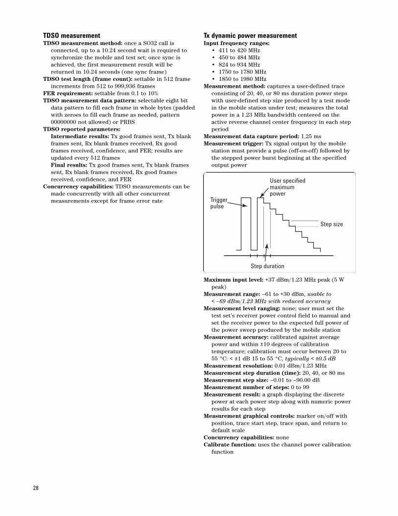
TDSO measurementTDSO measurement method: once a SO32 call is
connected, up to a 10.24 second wait is required to synchronize the mobile and test set; once sync is achieved, the first measurement result will be returned in 10.24 seconds (one sync frame)
TDSO test length (frame count): settable in 512 frame increments from 512 to 999,936 frames
FER requirement: settable from 0.1 to 10%TDSO measurement data pattern: selectable eight bit
data pattern to fill each frame in whole bytes (paddedwith zeroes to fill each frame as needed, pattern 00000000 not allowed) or PRBS
TDSO reported parameters: Intermediate results: Tx good frames sent, Tx blank frames sent, Rx blank frames received, Rx good frames received, confidence, and FER; results are updated every 512 framesFinal results: Tx good frames sent, Tx blank frames sent, Rx blank frames received, Rx good frames received, confidence, and FER
Concurrency capabilities: TDSO measurements can be made concurrently with all other concurrent measurements except for frame error rate
Tx dynamic power measurementInput frequency ranges:
• 411 to 420 MHz• 450 to 484 MHz• 824 to 934 MHz• 1750 to 1780 MHz• 1850 to 1980 MHz
Measurement method: captures a user-defined trace consisting of 20, 40, or 80 ms duration power steps with user-defined step size produced by a test mode in the mobile station under test; measures the total power in a 1.23 MHz bandwidth centered on the active reverse channel center frequency in each step period
Measurement data capture period: 1.25 msMeasurement trigger: Tx signal output by the mobile
station must provide a pulse (off-on-off) followed by the stepped power burst beginning at the specified output power
Maximum input level: +37 dBm/1.23 MHz peak (5 W peak)
Measurement range: –61 to +30 dBm, usable to < –69 dBm/1.23 MHz with reduced accuracy
Measurement level ranging: none; user must set the test set’s receiver power control field to manual and set the receiver power to the expected full power of the power sweep produced by the mobile station
Measurement accuracy: calibrated against average power and within ±10 degrees of calibration temperature; calibration must occur between 20 to 55 °C: < ±1 dB 15 to 55 °C, typically < ±0.5 dB
Measurement resolution: 0.01 dBm/1.23 MHzMeasurement step duration (time): 20, 40, or 80 msMeasurement step size: –0.01 to –90.00 dBMeasurement number of steps: 0 to 99Measurement result: a graph displaying the discrete
power at each power step along with numeric power results for each step
Measurement graphical controls: marker on/off with position, trace start step, trace span, and return to default scale
Concurrency capabilities: noneCalibrate function: uses the channel power calibration
function
28
Triggerpulse
User specifiedmaximumpower
Step size
Step duration

Maximum/minimum power measurementInput frequency ranges:
• 411 to 420 MHz• 450 to 484 MHz• 824 to 934 MHz• 1750 to 1780 MHz• 1850 to 1980 MHz
Measurement method: performs this sequence: • sets the test set source to a user-specified value for
the maximum power measurement• ranges the receiver to the expected power• sends all up power control bits • uses the average power meter to measure the
maximum power• sets the test set source to a user-specified value for
the minimum power measurement• ranges the receiver to the expected power• sends all down power control bits • uses the channel power meter to measure the
minimum power• returns the test set to the same state before the
measurement was initiatedMeasurement data capture period: 1.25 msMaximum input level: +37 dBm/1.23 MHz peak (5 W
peak)Measurement range:
Maximum power measurement: –10 to +30 dBm; usable from –10 to –20 dBm with reduced accuracy (peak detector only)Minimum power measurement: –61 to +30 dBm, usable to < –69 dBm/1.23 MHz with reduced accuracy
Measurement level ranging: auto for the maximum power measurement, and either auto or manual for the minimum power measurement
Measurement accuracy: Maximum power measurement: same as the average power measurement accuracyMinimum power measurement: same as the channel power measurement accuracy
Measurement settings: maximum power measurement cell power, maximum power measurement F-FCH level, maximum power measurement F-Pilot level, minimum power measurement cell power, minimum power measurement F-FCH level, and minimum power measurement F-Pilot level
Measurement result: the measured maximum power and minimum power
Concurrency capabilities: noneCalibrate function: uses the channel power calibration
function
Multi-tone audio measurementMulti-tone analyzer supported service options: SO3,
SO17, and SO32768Multi-tone audio measurement mode: downlink audio
(base station to mobile station) or uplink audio (mobile station to base station)
Multi-tone analyzer 0 dB reference mode: relative or absolute
Multi-tone analyzer 0 dB reference tone (relative mode): tone 0 through 20
Multi-tone analyzer downlink reference level (absolute mode): 1 mV to 5.000 V
Multi-tone analyzer uplink reference level (absolute mode): 0.1 to 100.0%
Multi-tone analyzer expected audio input peak voltage(downlink mode): 1 mV to 20.000 V
Multi-tone analyzer device settling time: 10 to 1000 msMulti-tone analyzer SINAD/distortion state
(in the 1 tone mode only): selectable on or offMulti-tone analyzer downlink encoder settling: 0 to
100 framesMulti-tone downlink generator frequency presets:
narrow: 300 Hz, 400 Hz, 500 Hz, 600 Hz, 700 Hz, 800 Hz, 900 Hz, 1 kHz, 1.1 kHz, 1.2 kHz, 1.3 kHz, 1.4 kHz, 1.6 kHz, 1.8 kHz, 2.0 kHz, 2.2 kHz, 2.4 kHz,2.6 kHz, 2.8 kHz, and 3.0 kHz
normal: 300 Hz, 600 Hz, 800 Hz, 1 kHz, 1.2 kHz, 1.6 kHz, 2.0 kHz, 2.4 kHz, 2.8 kHz, and 3.0 kHz
wide: 100 Hz, 200 Hz, 300 Hz, 400 Hz, 500 Hz, 600 Hz, 700 Hz, 800 Hz, 900 Hz, 1 kHz, 1.2 kHz, 1.4 kHz, 1.6 kHz, 1.8 kHz, 2.0 kHz, 2.4 kHz, 2.8 kHz,3.0 kHz, 3.3 kHz, and 3.6 kHz
Multi-tone downlink generator frequency single tones:300 Hz, 600 Hz, 800 Hz, 1 kHz, 1.2 kHz, 1.6 kHz, 2 kHz, 2.4 kHz, 2.8 kHz, or 3 kHz
Multi-tone downlink generator frequency level: 10, 30, or 50% of total level
Multi-tone uplink generator frequency presets: same as downlink presets or user selectable for up to 20 tones; user frequency range from 10 Hz to 4.0 kHz
Multi-tone uplink generator frequency level: specified total rms voltage range from 20 mV to 1.42 V
Multi-tone analyzer measurement results (SINAD/distortion mode off): graphical display of up to twenty tones with level (frequency response)
Multi-tone analyzer measurement results (SINAD/distortion mode on): tone audio level, tone audio frequency, tone SINAD, and tone distortion
Multi-tone analyzer measurement limits: upper and lower tone pas/fail limit for each active tone; range of–100 to +100 dB for each limit
Concurrency capabilities: none
29

Option 004 Digital BusFunctionality: allows baseband, digital I/Q data from
the signal generator to be sent to an external N5101ABaseband Studio PCI Card for fading and then returned to the test set for modulation
Connector: rear panel, 50 pin high densitySignal generator ALC mode: closed or open (default of
closed); open loop mode must be used during fading to maintain the desired signal characteristics
ALC open loop calibration: calibrates the RF source when operating in the ALC open loop mode; the accuracy remains valid with a ±5 °C window of the temperature at which the calibration was performed
ALC open loop RF in/out composite absolute output level accuracy degradation (must add this to the main level accuracy specification for temperatures within ±5 °C of the last ALC open loop calibration):< ±0.75 dB, –109 to –70 dBm/1.23 MHz,< ±0.50 dB, –70 to –35 dBm/1.23 MHz,< ±0.75 dB, –35 to –13 dBm/1.23 MHz
ALC open loop RF out only composite absolute outputlevel accuracy degradation (must add this to the main level accuracy specification):< ±0.75 dB, –109 to –70 dBm/1.23 MHz,< ±0.50 dB, –70 to –35 dBm/1.23 MHz,< ±0.75 dB, –35 to –13 dBm/1.23 MHz
ALC open loop carrier feedthrough: typically < 40 dBc, (nominal ambient < 47 dBc after IQ calibration)
General SpecificationsTimebase specificationsInternal high stability 10 MHz oven-controlled crystal oscillator (OCXO)Aging rates: < ±0.1 ppm per year, < ±0.005 ppm peak-to-
peak per day during any 24-hour period starting 24 hours or more after a cold start
Temperature stability: < ±0.01 ppm frequency variation from 25 °C over the temperature range 0 to 55 °C
Warm-up times: 5 minutes to be within ±0.1 ppm of frequency at one hour, 15 minutes to be within ±0.01 ppm of frequency at one hour
Accuracy after a 30-minute warm-up period of continuous operation is derived from:typically ±[(time since last calibration) x (aging rate) + (temperature stability) + (accuracy of calibration)]
Initial adjustment: typically ±0.03 ppm
External reference inputInput frequency: 10 MHzInput frequency range: typically < ±5 ppm of nominal
reference frequencyInput level range: typically 0 to +13 dBmInput impedance: typically 50 Ω
External reference outputOutput frequency: same as timebase (internal 10 MHz
OCXO or external reference input)Output level: typically > 0.5 V rmsOutput impedance: typically 50 Ω
Trigger outputFrame clock output: selectable output of 20 ms, 80 ms,
or 2 s
Remote programmingGPIB: IEEE Standard 488.2GPIB help: pressing the front panel Help key and then
any other key will cause the test set to display the GPIB syntax for that command at the bottom of the front panel display; pressing the Help key again exits this mode of operation
Remote front panel lockout: allows remote user to disable the front panel display to improve GPIB measurement speed
Implemented functions: T6, TE0, L4, LE0, SH1, AH1, RL1, SR1, PP0, DC1, DT0, C0, and E2
Save/Recall registersStorage capacity: five registers that store the complete
instrument state except for active cell call processing status (fixed labels of register 1 to 5); registers are non-volatile
Recall: allows user to recall one of the 5 stored instrument states
30
General specificationsDimensions (H x W x D): 8.75 x 16.75 x 24.63 inches
(222 x 426 x 625 mm), 7 rack spaces highWeight: 66 lbs (30 kg)Display: 10.5 inches (26.7 cm), active matrix, color,
liquid crystalLAN (local area network) port (for firmware upgrades
and protocol logging only): RJ-45 connector, 10 base T Ethernet with TCP/IP support
Operating temperature: 0 to +55 °CStorage temperature: –20 to +70 °CPower: 100 to 240 Vac, 50 to 60 Hz, 550 VA maximumCalibration interval: two yearsEMI: conducted and radiated interference meets
CISPR-11Radiated leakage due to RF generator: typically < 1 µV
induced in a resonant dipole antenna one inch fromany surface except the underside and rear panel at set RF generator output frequency and output level of –40 dBm
Spurious leakage: typically < 5 µV induced in a resonant dipole antenna one inch from any surface except the underside and rear panel at frequencies other than the RF generator output frequency and output level of –40 dBm
Power consumption: typically 400 to 450 W continuousMeasurement speed: typical measurement speed based
on using at least a 600 MHz Pentium II processor PCand with the display off mode selected on the E5515C; measurement speeds include the total time from GPIB measurement request until the controller receives the result using the INT/FETCH commands; due to variations of trigger latencies and internal test set processor loading, individual measurement times may be faster or slower; measurement speeds also vary depending on the controller GPIB environment and processor speed
Analog measurementsMeasurement name One measurement Five measurements
Analog Tx power 15 ms 41 msFrequency modulation 134 ms 448 ms(with deviation result)Frequency modulation 163 ms 528 ms(with deviation and distortion results)Frequency stability 174 ms 754 msAudio analyzer 65 ms 284 ms(with level result)Audio analyzer 96 ms 314 ms(with level, SINAD and distortion results)
CDMA measurementsMeasurement name One measurement Ten measurements
Channel power 73 ms 616 ms(normal mode)Channel power 28 ms 210 ms(fast mode)Channel power 9 ms 34 ms (very fast mode)Average power (RC3) 199 ms 1773 msWaveform quality 170 ms 1001 msIS-95, RC1, or RC2Waveform quality 202 ms 1385 msIS-2000 RC3/4Code channel time 299 ms 2326 msand phase errorHandoff waveform 735 ms NAqualityGated power 157 ms 3352 ms(100 measurements)Tx spurious response 338 ms 2566 msTime response of 1210 ms NAopen loop power
31

Pentium III is a U.S. registered trademark Intel, Corp.
Windows 98, Windows NT 4.0, Windows 2000 are U.S. registered trademarks ofMicrosoft Corp.
For more information please visit our Web site at:www.agilent.com/find/8960
www.agilent.com
Agilent Technologies’ Test and Measurement Support, Services, and AssistanceAgilent Technologies aims to maximize the value you receive, while minimizingyour risk and problems. We strive to ensure that you get the test and measure-ment capabilities you paid for and obtain the support you need. Our extensivesupport resources and services can help you choose the right Agilent productsfor your applications and apply them successfully. Every instrument and systemwe sell has a global warranty. Two concepts underlie Agilent’s overall support policy: “Our Promise” and “Your Advantage.”
Our PromiseOur Promise means your Agilent test and measurement equipment will meet its advertised performance and functionality. When you are choosing newequipment, we will help you with product information, including realistic per-formance specifications and practical recommendations from experienced testengineers. When you receive your new Agilent equipment, we can help verifythat it works properly and help with initial product operation.
Your AdvantageYour Advantage means that Agilent offers a wide range of additional expert testand measurement services, which you can purchase according to your uniquetechnical and business needs. Solve problems efficiently and gain a competitiveedge by contracting with us for calibration, extra-cost upgrades, out-of-warrantyrepairs, and onsite education and training, as well as design, system integration,project management, and other professional engineering services. ExperiencedAgilent engineers and technicians worldwide can help you maximize your produc-tivity, optimize the return on investment of your Agilent instruments and systems,and obtain dependable measurement accuracy for the life of those products.
United States: Korea:
(tel) 800 829 4444 (tel) (080) 769 0800
(fax) 800 829 4433 (fax) (080) 769 0900
Canada: Latin America:
(tel) 877 894 4414 (tel) (305) 269 7500
(fax) 800 746 4866 Taiwan:
China: (tel) 0800 047 866
(tel) 800 810 0189 (fax) 0800 286 331
(fax) 800 820 2816 Other Asia Pacific
Europe: Countries:
(tel) 31 20 547 2111 (tel) (65) 6375 8100
Japan: (fax) (65) 6755 0042
(tel) (81) 426 56 7832 Email: [email protected]
(fax) (81) 426 56 7840 Contacts revised: 09/26/05
For more information on Agilent Technologies’ products, applications or services,
please contact your local Agilent office. The complete list is available at:
www.agilent.com/find/contactus
Product specifications and descriptions in this document subject to change without notice.
© Agilent Technologies, Inc. 2003, 2004, 2005, 2006Printed in USA March 7, 20065988-6180EN
www.agilent.com/find/emailupdatesGet the latest information on the products and applications you select.
Agilent Email Updates
www.agilent.com/find/agilentdirectQuickly choose and use your test equipment solutions with confidence.
Agilent Direct
Agilent Open
www.agilent.com/find/openAgilent Open simplifies the process of connecting and programmingtest systems to help engineers design, validate and manufacture electronicproducts. Agilent offers open connectivity for a broad range of system-ready instruments, open industry software, PC-standard I/O and globalsupport, which are combined to more easily integrate test systemdevelopment.