agilent 33500b waveform generator · web viewelectronics documentation agilent 33500b waveform...
TRANSCRIPT

Electronics Documentation
Agilent 33500B Waveform Generator 1Link to Manufacturer’s Manual 23 Sentence Description 2Physical Limitations 3Project Ideas (with links to content) 3Startup Procedure 3Operation of equipment 3
CSI3003X III DC Regulated Dual Power Supply 5
Agilent 34401A 6 1/2 Digitial Multimeter 9
Tektronix MSO 2014 Mixed Signal Oscilloscope 11
Weller Soldering Irons 14
Mastech MS8217 Muiltimeter 16
Sparkfun VC830L Multimeter 17
Extech Instruments 38389 AC/DC Clamp Meter 18
Digital Thermometer 6802 II 20
Weller ZeroSmog EL 20
Hakko FA-400 Smoke Absorber 22
Solder Removal 23
Helping Hands 23
Connector Types 23
Circuit Mill 23
Agilent 33500B Waveform GeneratorAuthor: Alex DeBateName of Machine
Agilent 33500B Waveform Generator

Link to Manufacturer’s Manual
https://literature.cdn.keysight.com/litweb/pdf/5991-0692EN.pdf
Picture of Tool in Space
Figure 1 - The Agilent 33500B Function Generator
3 Sentence Description
The waveform generator is capable of producing various voltage waveforms used to power circuits. Waveform parameters such as amplitude, frequency, DC offset, and phase can be adjusted. It is capable of outputting two distinct signals at the same time.
Physical Limitations
• Maximum frequency: 20 MHz• Maximum peak-to-peak voltage: 20 volts• Maximum DC voltage: 5 volts• Channels: 2

• Waveforms available: Sine, square, ramp, pulse, triangle, Gaussian noise, PRBS (Pseudorandom Binary Sequence), DC
Project Ideas (with links to content)
Controlling an RC car with a waveform generator (https://www.youtube.com/watch?v=NVQWIyXA_kw)
Operational amplifiers (Also known as op-amps) are very common circuit components used to alter the waveform of voltage inputs. Ten fundamental op-amp applications can be found at (https://www.arrow.com/en/research-and-events/articles/fundamentals-of-op-amp-circuits)
Startup Procedure
Simply power on the waveform generator by pressing the power button. It will take a moment to boot up.
Operation of equipment
Figure 2 - Function Generator Interface
1. Connect a BNC cable from the desired channel output to the circuit. a. If both channels are to be used in tandem, they should be synchronized. Press the “trigger” hard button, then press the “Sync” soft button to turn on synchronization.2. To change the parameters of a specific channel, press the appropriate channel selection button. The display will change to display the parameters of that channel’s output waveform.3. Press the “Waveforms” hard button to pull up the list of possible output waves. To change which type of wave is outputted, select the appropriate soft button.4. To change waveform parameters:a. Press the “Parameters” hard button.b. Press the appropriate soft button for the parameter you wish to changec. The parameter value can be set using two methods:i. Type the desired value using the number pad, then select the appropriate unit magnitude (e.g. Hz, kHz, MHz, etc.) using the soft buttons.ii. Use the two arrows under the adjustment knob to select a digit, then turn the knob to adjust its value.5. Pressing the “Units” hard button allows for the switching between frequency or period, amplitude/offset or high/low, and amplitude as peak-to-peak or RMS

6. Note: if taking oscilloscope measurements, select the output load soft button and set it to “High Z”. Never take the output amplitude at face value, always measure it using an oscilloscope or Digital Multimeter.7. Once the waveform and parameters are chosen, press the “output” soft button to turn on the channel.8. Function settings can be saved and recalled using the “System” hard button menu. Settings can be saved to the FG or to a portable flash drive.9. The additional hard buttons offer additional control:a. “Modulate” can modulate the signal as either FM or AM.b. “Sweep” allows for the controlled, periodic alteration of the signal frequency.c. “Burst” pulses the voltage as dictated by the set parameters.
Shutdown Procedure and Clean Up
To shut off the generator, hold down the power button until the display goes dark. Return BNC cables to the rack. Clear desk of scrap wire and components.
Basic Troubleshooting
• The amplitude is half/twice what is set.o Change output load between High-Z, 50 Ohms, or a specific load.• The function generator is not powering on.o Check that the power cable is plugged in, and make sure that the electrical station is also plugged in.• When restarted, the function generator will always reset the outputs to 1 kHz, 100 mVpp sine waves.
References
Keysight Technologies. (2018, July 18). 33500B Series Waveform Generator Data Sheet. Retrieved from Keysight: https://literature.cdn.keysight.com/litweb/pdf/5991-0692EN.pdf?id=2202606
CSI3003X III DC Regulated Dual Power Supply

Author:Alex DeBateName of Machine
CSI3003X III DC Regulated Dual Power Supply
Link to Manufacturer’s Manual
https://www.circuitspecialists.com/products/pdf/CSI3003X3.pdf
Picture of Tool in Space
Figure 1 - The CSI3003X III
3 Sentence Description
A DC power supply output a direct-current voltage that can be used to power electrical components and circuitry. The CSI3003X has three outputs, two that provide variable DC voltages and one that provides constant 5 volts.
Physical Limitations
Max voltage output = 30V DCMax current output = 3A parallel, 6A in seriesNumber of outputs = 2

Rated for 110V AC input only, and is protected by a fuse
Project Ideas (with links to content)
The prototyping instructor checklist walks through the construction of a simple, DC powered LED circuit (https://drive.google.com/file/d/0B9s-PmFmfjJHUXU1TWw4bHh2RmM/view)
Operational amplifiers (Also known as op-amps) are very common circuit components that must receive DC power in order to function. Ten fundamental op-amp applications can be found at (https://www.arrow.com/en/research-and-events/articles/fundamentals-of-op-amp-circuits)
Startup Procedure
Figure 2 - Labels for referenceFor startup procedure and equipment operation, reference figure 2.
Before connecting the DC power supply to a circuit, turn it on by pressing button 5, labeled “POWER.” Rotate knobs until both supplies read 0.0V and 0A. Zeroing the power supply ensures that a voltage higher than expected will not be applied to the circuit.

Operation of equipment
The CSI3003X III allows for the control of the current and amplitude of the DC voltage supplied. In addition to the two variable supplies, a constant 5V supply is located in the center of the interface. The interface, as labelled in figure 2, is:
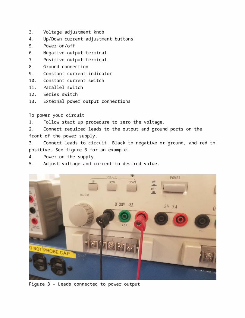
1. Current amplitude indicator2. Voltage amplitude indicator3. Voltage adjustment knob4. Up/Down current adjustment buttons5. Power on/off6. Negative output terminal7. Positive output terminal8. Ground connection9. Constant current indicator10. Constant current switch11. Parallel switch12. Series switch13. External power output connections
To power your circuit1. Follow start up procedure to zero the voltage.2. Connect required leads to the output and ground ports on the front of the power supply.3. Connect leads to circuit. Black to negative or ground, and red to positive. See figure 3 for an example.4. Power on the supply.5. Adjust voltage and current to desired value.

Figure 3 - Leads connected to power output
Basic Troubleshooting
Power supply is not turning on1. Disconnect power supply from circuit2. Check that the power supply is plugged into an outlet. 3. If the supply is plugged in and still not receiving power, change it to another outlet.4. If power supply is connected to the electronics bench, ensure the bench is powered.5. If problem persists, ask a prototyping instructor for help. The internal fuse of the CSI3003X III may need to be changed.
References
Circuit Specialists, Inc. (2018, July 7). CSI3003X3 User Manual. Retrieved from Circuit Specialists: https://www.circuitspecialists.com/products/pdf/CSI3003X3.pdf
Agilent 34401A 6 1/2 Digital Multimeter
Author: Collin Morris
Tool Name
Agilent 34401A 6 1/2 Digital Multimeter
Link to Manufacturer’s Manualhttp://literature.cdn.keysight.com/litweb/pdf/34401-90013.pdfPicture of Tool
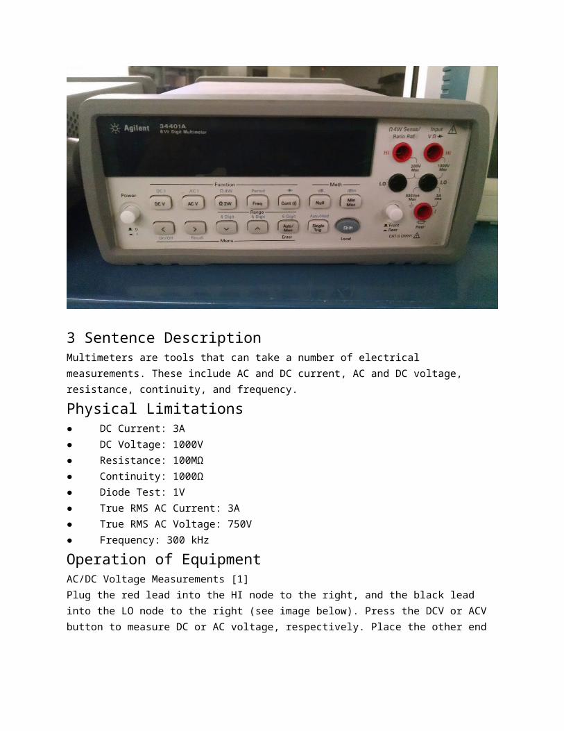
3 Sentence Description Multimeters are tools that can take a number of electrical measurements. These include AC and DC current, AC and DC voltage, resistance, continuity, and frequency.
Physical Limitations● DC Current: 3A● DC Voltage: 1000V● Resistance: 100MΩ● Continuity: 1000Ω● Diode Test: 1V● True RMS AC Current: 3A● True RMS AC Voltage: 750V● Frequency: 300 kHz
Operation of EquipmentAC/DC Voltage Measurements [1]Plug the red lead into the HI node to the right, and the black lead into the LO node to the right (see image below). Press the DCV or ACV button to measure DC or AC voltage, respectively. Place the other end of the red lead on the positive side of the circuit or component, and the black lead on the other side and read the measurement displayed.

Measure AC/DC VoltageAC/DC Current Measurements [1]Plug the red lead into the REAR node, and the black lead into the LO voltage node (see image below). Press Shift and the DCV or ACV button to measure DC or AC voltage, respectively. Place the other end of the red lead on the positive side of the circuit or component, and the black lead on the other side and read the measurement displayed. Measure AC/DC CurrentResistance Measurements [1]Plug the red lead into the left HI node, and the black lead into the left LO node (see image below). Press the Ω2W to measure resistance. Place the other end of the red lead on one side of a component, and the black lead on the other side and read the measurement displayed. Measure ResistanceFrequency and Period Measurements [1]Plug the red lead into the HI node to the right, and the black lead into the LO node to the right (same as for Measure AC/DC Voltage). Press the Freq button to measure frequency, and Shift + Freq to measure period. Place the other end of the red lead on the positive side of the circuit or component, and the black lead on the other side and read the measurement displayed. Continuity Test [1]With the same set up as previous, press the Cont button to test continuity. Check Diodes [1]With the same set up as previous, press Shift and the Cont button to test diodes.
Basic TroubleshootingIf the Multimeter Does Not Turn On [1]First, verify that the multimeter’s Power switch is in the “On” position. Also, make sure that the power cord is firmly plugged into the power module on the rear panel.Verify the power-line voltage setting. Change the voltage setting if it is not 120V (AC).Verify that the power-line fuse is good. The multimeter is shipped from the factory with a 250 mA fuse installed. This is the correct fuse for all line voltages.
References[1] Keysight . (2014). Keysight 34401A 6 1/2 Digit Multimeter Service Guide (9th ed.) Santa Clara, CA.
Tektronix MSO 2014 Mixed Signal Oscilloscope
Author: Alex DeBate
Name of Machine
Tektronix MSO 2014 Mixed Signal Oscilloscope
Link to Manufacturer’s Manual
https://www.tek.com/oscilloscope/mso2000-dpo2000-manual-0#
Download link for the manual is on page
Picture of Tool in Space
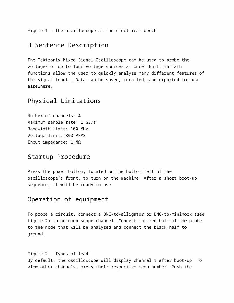
Figure 1 - The oscilloscope at the electrical bench
3 Sentence Description
The Tektronix Mixed Signal Oscilloscope can be used to probe the voltages of up to four voltage sources at once. Built in math functions allow the user to quickly analyze many different features of the signal inputs. Data can be saved, recalled, and exported for use elsewhere.
Physical Limitations
Number of channels: 4Maximum sample rate: 1 GS/sBandwidth limit: 100 MHzVoltage limit: 300 VRMSInput impedance: 1 MΩ
Startup Procedure
Press the power button, located on the bottom left of the oscilloscope’s front, to turn on the machine. After a short boot-up sequence, it will be ready to use.
Operation of equipment

To probe a circuit, connect a BNC-to-alligator or BNC-to-minihook (see figure 2) to an open scope channel. Connect the red half of the probe to the node that will be analyzed and connect the black half to ground. Figure 2 - Types of leadsBy default, the oscilloscope will display channel 1 after boot-up. To view other channels, press their respective menu number. Push the channel menu button again to set vertical parameters for input waveforms and to display or remove the corresponding waveform from the display.If there is current flowing in the circuit, the oscilloscope should now be displaying the voltage waveform for the connected node.
On the bottom left of the display, the channel and a voltage value will be shown. This voltage value is the number of volts per division, where division refers to the dotted square regions of the display. Time per division is displayed in the information box to the right of volts/division, and is shared for all channels.
Press “Autoset” to have the software automatically scale the display. If needed, the volts/div can be manually scaled using the “vertical scale” knobs. To adjust time/div, use the “horizontal scale” knob. Each channel can have a unique volts/div scale, whereas all channels share the same time/div scale.
Note that voltage is measured relative to ground, with values above ground being positive and values below ground being negative. Ground is indicated for each channel with a numbered arrow on the left side of the display. If the channel waveforms are overlapping, the position of ground can be adjusted using the “vertical position” knobs above each channel. See figure 3 for an example of two channels being displayed at once, with their grounds offset for easier reading.
Figure 3 - Two signals at onceTriggering is an important function of oscilloscopes. enables the scope to display a steady image on the screen that can be viewed by the user. Without a trigger, or other form of synchronization, it would not be possible to display a steady signal on the screen (Poole).For a comprehensive tutorial on oscilloscope triggers, read this article: (https://www.radio-electronics.com/info/t_and_m/oscilloscope/oscilloscope-trigger.php) or view this video: (https://www.youtube.com/watch?v=H0Czb2zBzsQ). The method of triggering can be changed by pressing the “Trigger Menu” hard button.
To take more precise measurements, activate cursors by pressing the “cursors” hard button. Pressing once will activate vertical cursors, pressing it a second time switches to horizontal cursors, and a third press will turn the cursors off. In figure 3, vertical cursors are activated; they
are the vertical lines intersecting the two waveforms. Cursors usually come in pairs, so you can measure the difference between one and the other. (JIMB0)
Cursors allow for more precise measurements for two reasons:1. They can compare values between two points on the same waveform. This can be used to measure, for example, accurate peak-to-peak voltage, time constants, etc.2. They can compare values between two different waveforms. This is good for comparing a circuit’s input signal to its output signal.
Finally, the last fundamental use of the oscilloscope is to perform more complex mathematical analysis of inputs. The oscilloscope has a number of built-in math functions that can be accessed by pressing the “math” hard button and selecting the appropriate values. While an in-depth discussion of these math functions is outside of the scope of this article, a good starting point can be found here: https://www.testandmeasurementtips.com/basics-math-functions-oscilloscopes/
In addition to onboard math functions, data can be exported for use in other analysis software, such as MATLAB and excel. To export data, insert a portable USB drive into the USB slot directly above the power button. Pressing the “Save” hard button will automatically save a copy of the waveform data and a screenshot of the display to the inserted drive.
Shutdown Procedure and Cleanup
Simply press the power button again to shut down the oscilloscope. Place all cables and leads back onto the cable rack.
Basic troubleshooting
If the signal is not displaying correctly:1. Press “autoset” to automatically scale the display. This usually fixes the issue.2. If the signal is jittery or rolling across the screen, try adjusting the triggering. For more information on triggering, read this article from Radio Electronics: https://www.radio-electronics.com/info/t_and_m/oscilloscope/oscilloscope-trigger.php3. Reset the display to default settings by pressing “Default Setup” next to the “save” and “menu” buttons.
Advanced troubleshooting/maintenance
Most display problems are a result of bad triggering, sometimes resulting from unsynchronized channels. For more advanced solutions regarding channel synchronization and triggering options, consult pages 64-75 of the MSO 2014 manual.
References
JIMB0. (n.d.). How to Use an Oscilloscope. Retrieved from Sparkfun: https://learn.sparkfun.com/tutorials/how-to-use-an-oscilloscope/using-an-oscilloscopePoole, I. (n.d.). Oscilloscope Trigger / Triggering Tutorial. Retrieved from Radio-Electronics: https://www.radio-electronics.com/info/t_and_m/oscilloscope/oscilloscope-trigger.phpTektronix, Inc. (2018, July 8). Tektronix MSO 2014 Mixed Signal Oscilloscope. Retrieved from Tektronix: https://www.tek.com/oscilloscope/mso2000-dpo2000-manual-0#
Weller Soldering Irons
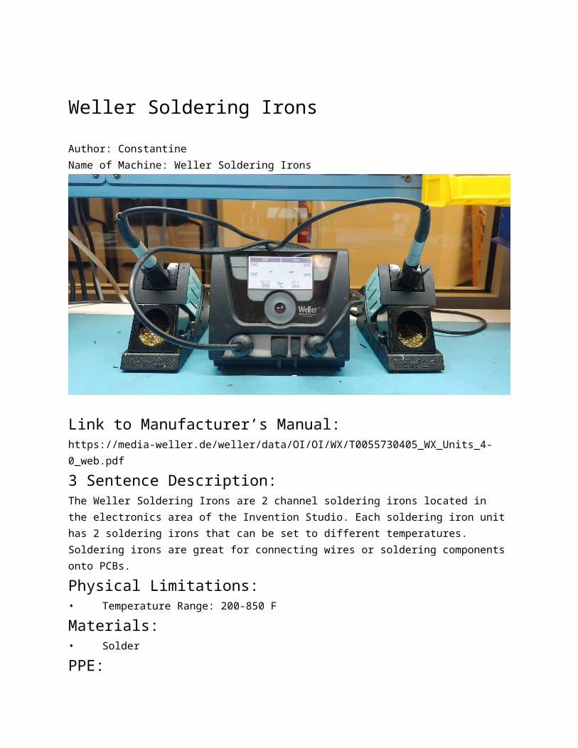
Author: ConstantineName of Machine: Weller Soldering Irons
Link to Manufacturer’s Manual:https://media-weller.de/weller/data/OI/OI/WX/T0055730405_WX_Units_4-0_web.pdf
3 Sentence Description:The Weller Soldering Irons are 2 channel soldering irons located in the electronics area of the Invention Studio. Each soldering iron unit has 2 soldering irons that can be set to different temperatures. Soldering irons are great for connecting wires or soldering components onto PCBs.
Physical Limitations:• Temperature Range: 200-850 F

Materials:• Solder
PPE:Since soldering can produce harmful fumes, use in conjunction with the Hakko FA-400 Smoke Absorber or the Weller ZeroSmog EL.
E-Stops and Safety Procedures:
Startup Procedure:
Operation:
Recommended Clean-Up:Make sure to clean any excess solder from around the work station. Wipe the tip of the soldering iron in the metal sponge at the base of the soldering iron holder. Turn off the soldering iron by holding down on the two green buttons on the soldering iron side of the center console.
References:Weller Manual[PDF]. (n.d.).https://media-weller.de/weller/data/OI/OI/WX/T0055730405_WX_Units_4-0_web.pdf
Mastech MS8217 Muiltimeter
Author: Collin MorrisTool NameMastech MS8217 Multimeter
Link to Manufacturer’s ManualManual included in zipped files.
Picture of Tool
3 Sentence Description Multimeters are tools that can take a number of electrical measurements. These include AC and DC current, AC and DC voltage, resistance, continuity, frequency, and temperature.
Operation of EquipmentAC/DC Current Measurements [1]1. Turn off all power to the circuit,

2. Insert the black test lead into the COM terminal. Insert the red test lead into mA terminal for a max of 400 mA, for up to 10A insert the red test lead into the A terminal.3. Set the rotary switch to the µA, mA, or A range. If the range of the measured current is not known, select the higher range first then move to the lower range if necessary. 4. Press the yellow key to select DCA or ACA measuring mode.
Basic TroubleshootingLow Resistance Reading as ZeroShort the test leads before measurement and memory the probe resistance.This is necessary to subtract the resistance of the test leads
ReferencesDigital Multimeter User’s Manual
Sparkfun VC830L Multimeter
Author: SidName:Sparkfun VC830L Multimeter
Manual:https://www.sparkfun.com/products/12966 Picture:
Description:The multimeter is an all purpose tool for electrical testing. Using the probes, this tool measures voltage, resistance, current, for both AC and DC signals. It can also measure continuity in circuit in different voltage and current ranges from milli to Mega.
Operation:Plug the red banana lead into the rightmost port. Plug the black lead into the middle COM port. Turn the middle know to point to the quantity and range to be measured (Volts, Amps, Resistance)Gently touch the red probe to the live end of the desired circuit to measure. Gently touch the black probe to the ground node of the circuit. Be careful not to touch the metal or the circuit while it is powered on.The value should show up on the display.
Troubleshooting:

Make sure the battery is fully chargedMake sure the metal end of the probe is contacting metal on the circuit.Make sure the circuit is designed correctly and powered on correctly
References:https://www.sparkfun.com/products/12966
Extech Instruments 38389 AC/DC Clamp Meter
Author: Collin MorrisTool NameExtech Instruments 38389 AC/DC Clamp Meter
Link to Manufacturer’s Manualhttp://www.extech.com/resources/38389_UM-en.pdf
Picture of Tool Image Source: Extech
3 Sentence Description The AC/DC Clamp Meter is a tool that can take a number of electrical measurements. These include high AC and DC current, AC and DC voltage, resistance, continuity, capacitance, and temperature.
Physical Limitations● Current: 600A● Voltage: 600V DC/AC● Resistance, Capacitance, Diode Test: 250V DC/AC● Temperature: 60V DC, 24V AC
PPENo personal protective equipment is necessary for the AC/DC Clamp Meter.
Operation of EquipmentAC/DC Current Measurements [1]WARNING: Ensure that the test leads are disconnected from the meter before making current clamp measurements. 1. Set the Function switch to the 600 or 400A range. If the range of the measured current is not known, select the higher range first then move to the lower range if necessary.
2. Select AC or DC with the AC/DC button. Press the zero button to zero the meter in the DCA mode only. 3. Press the trigger to open jaw. Fully enclose one conductor to be measured. 4. The clamp meter LCD will display the reading. AC/DC Voltage Measurements [1]1. Insert the black test lead into the negative COM terminal and the red test lead into the positive V terminal.2. Set the function switch to the V position.3. Select AC or DC with the AC/DC button.4. Connect the test leads in parallel to the circuit under test.5. Read the voltage measurement on the LCD display. Resistance and Continuity Measurements [1]1. Insert the black test lead into the negative COM terminal and the red test lead into the positive terminal. 2. Set the function switch to the •))) Ω CAP position3. Use the multifunction button to select resistance. 4. Touch the test probe tips across the circuit or component under test. It is best to disconnect one side of the device under test so the rest of the circuit will not interfere with the resistance reading. 5. For Resistance tests, read the resistance on the LCD display. 6. For Continuity tests, if the resistance is < 30Ω, a tone will sound. Capacitance Measurements [1]WARNING: To avoid electric shock, discharge the capacitor under test before measuring.1. Set the function switch to the •))) Ω CAP position2. Press the multifunction button to select the capacitance function. 3. Insert the black test lead banana plug into the negative (COM) jack and the red test lead banana plug into the positive jack. 4. Touch the test probe tips across the part under test. 5. Read the capacitance in the display. 6. The display will indicate the proper decimal point and value. Temperature Measurements [1]WARNING: To avoid electric shock, disconnect both test probes from any source of voltage before making a temperature measurement. 1. Set the function switch to TEMP. 2. Insert the Temperature Probe into the negative (COM) and the positive jacks, making sure to observe the correct polarity. 3. Touch the Temperature Probe head to the part whose temperature you wish to measure. Keep the probe touching the part under test until the reading stabilizes (about 30 seconds). 4. Read the temperature in the display. The digital reading will indicate the proper decimal point and value. WARNING: To avoid electric shock, be sure the thermocouple has been removed before changing to another measurement function Data Hold [1]

To freeze the LCD meter reading, press the data hold button. The data hold button is located on the left side of the meter (top button). While data hold is active, the DH display icon appears on the LCD. Press the data hold button again to return to normal operation. Peak Hold [1]To hold the highest reading on the LCD, press the peak hold button. The peak hold button is located on the left side of the meter (bottom button). The meter reading will not change as readings change, rather it will only display the highest reading encountered since the peak hold button was pressed. Press the peak hold button again to return to normal operation.
References[1] EXTECH Instruments. (2015). 600A True RMS AC/DC Clamp Meter Model 38389. Nashua, NH
Digital Thermometer 6802 II
Author: NONE
Weller ZeroSmog EL
Author: Alex DeBate
https://www.weller.com.pl/en_US/p/file/b1f36002edf089e5b86ec4c223abb31a/Manual_ZeroSmog_EL_DE_GB_ES_FR_IT_PT_NL_SV_DK.pdf
Name of Machine
Weller Zero Smog EL
Link to Manufacturer’s Manual
Link to manual (https://www.weller.com.pl/en_US/p/file/b1f36002edf089e5b86ec4c223abb31a/Manual_ZeroSmog_EL_DE_GB_ES_FR_IT_PT_NL_SV_DK.pdf)

Picture of tool
Figure 1- The Weller Zero Smog EL
3 Sentence Description
The Weller Zero Smog EL extracts and filters hazardous fumes from the electronics work areas. With two vacuum attachments, it can operate in two workstations at the same time. The vacuum ends can be adjusted by the user for better coverage.
Startup Procedure
1. Position the vacuum attachments for best coverage.
2. Power up the Zero Smog EL by flipping the switch located near the power inlet to the on position. See figure 2.
Figure 2 - Powering on the machine
3. Adjust the fan speed by pressing the “fan” icon on the front panel. See figure 3. Figure 3 - Adjusting fan speed
Basic Troubleshooting
Message or SymptomPossible Cause SolutionFumes not being extracted 1. Vacuum pipe attachment is leaking Reseal the pipe system
2. Filter is dirty Change the filterMachine is not running Machine is overheated and thermally switched off Leave the machine to cool down. Try switching on again after approximately 3 hours.Sub-micron particle becoming dirty too quickly Pre-filter is not being used Insert an M5 prefilter to collect fine dust
Advanced troubleshooting/maintenance

How to change a filter video link (https://www.youtube.com/watch?v=fVWcKaQ_OGo)
References
Weller Tools. (2018, July 7). Zero Smog EL Manual. Retrieved from Weller: https://www.weller.com.pl/en_US/p/file/b1f36002edf089e5b86ec4c223abb31a/Manual_ZeroSmog_EL_DE_GB_ES_FR_IT_PT_NL_SV_DK.pdfWeller Tools. (2018, July 7). Zero Smog EL Quick Start Guide. Retrieved from Weller: https://www.weller.com.pl/en_US/p/file/d9431d76262d4dcf54298c1f4fdce970/Manual_ZeroSmog_EL_Quick_Start.pdf
Hakko FA-400 Smoke Absorber
Author: ConstantineName of Machine: Hakko FA-400 Smoke Absorber
Link to Manufacturer’s Manual:https://doc.hakko.com/download.php?_gs=on&l=en&kp=FA-400&d=4706
3 Sentence Description:The Hakko Smoke Absorber is used to absorb and filter fumes from soldering. Depending on its orientation, it can be used to absorb widespread smoke or concentrated smoke. The Hakko should be used whenever soldering is taking place as solder fumes can be dangerous indoors.
Startup Procedure:1. Plug in the Hakko.2. Orient the Hakko filter down to absorb concentrated smoke or the filter facing the workspace to absorb widespread smoke. 3. Flick the power switch on the back of the Hakko to turn on. Advanced Troubleshooting/Maintenance:If the filter surface becomes white, the filter needs to be replaced.
References:Hakko FA-400. (n.d.). Retrieved from https://www.hakko.com/english/products/hakko_fa400.htmlHakko. (n.d.). Hakko FA-400 [PDF]. https://doc.hakko.com/download.php?_gs=on&l=en&kp=FA-400&d=4706

Solder Removal
Author: NONE
Helping Hands
Author: NONE
Connector Types
Author: NONE
Circuit Mill
Author: Tom