agile and adaptive qos aware management and discovery...
TRANSCRIPT

Agile and Adaptive QoS AwareManagement and Discovery in Service
Oriented Systems
THESIS
Submitted in partial fulfilmentof the requirements for the degree of
DOCTOR OF PHILOSOPHY
by
MONIKA SIKRI
Under the Supervision of
Dr. Rajkumar Gell
BIRLA INSTITUTE OF TECHNOLOGY ANDSCIENCE, PILANI
2016
Agile and Adaptive QoS AwareManagement and Discovery in Service
Oriented Systems
THESIS
Submitted in partial fulfilmentof the requirements for the degree of
DOCTOR OF PHILOSOPHY
by
MONIKA SIKRI
Under the Supervision of
Dr. Rajkumar Gell
BIRLA INSTITUTE OF TECHNOLOGY ANDSCIENCE, PILANI
2016

BIRLA INSTITUTE OF TECHNOLOGYAND SCIENCE, PILANI
CERTIFICATE
This is to certify that the thesis entitled Agile and Adaptive QoS Aware Man-
agement and Discovery in Service Oriented Systems submitted by Monika
Sikri ID No. 2007PHXF429P for award of Ph.D. of the Institute embodies
original work done by her under my supervision.
Signature of the Supervisor
Dr. RAJKUMAR GELL
Manager
Cisco Systems India Pvt Ltd
Bangalore
Date
i

ACKNOWLEDGEMENTS
Foremost, I would like to express my sincere gratitude to my supervisor Dr.
Rajkumar Gell for his continuous support for PhD research and study. His
guidance helped me during the complete research as well as writing the thesis.
Beside my current supervisor, I would like to acknowledge support from
my previous guide Dr Datta Subrahmanya. He was a great support in the
initial years of this journey. Due to his departure from Cisco, he couldn’t
support us beyond that in this endeavour.
I’m greatly indebted to my colleagues and managers at Cisco whose sup-
port has been a source of major comfort during hard times.
I am also grateful to BITS Pilani and it’s professors for allowing me to
pursue my passion and providing all the necessary help and support during
the complete journey.
And finally, this journey would not be possible without the support of
my family. Their unrelenting support kept me going all these years.
Monika Sikri
ii
ABSTRACT
Service Oriented Architecture is a widely adopted architectural paradigm to
model integration needs of the distributed enterprise systems. The tradi-
tional way of designing SOA systems could sustain monolithic development
methodology and static QoS-aware needs. However the same can no longer
support the adaptive and quality driven needs of measured and managed
service delivery.
In order to address this, an exhaustive review of the existing QoS-aware
design and discovery approaches supporting agile and adaptive needs of SOA
was carried out. It is realized that there is a scope and need to address QoS
progression in the adaptive layer of the SOA stack.
Considering the gaps this thesis intends to build the foundation for adap-
tive and QoS aware SOA systems. It argues the need for promoting adaptive
design for agile requirements. As a result, a modified Blitz QFD technique
is defined for requirements elicitation to yield prioritized set of agile require-
ments, promoting adaptive design.
Besides that a significant need for adaptive discovery framework is real-
ized, for an enterprise-wide adoption. An adaptive framework for QoS-aware
discovery is designed for redundant SOA services. In the process a light-
weight QoS domain specific language, classification and evaluation mecha-
nism, and a selection algorithm for ranking and choosing the best service
based on QoS goals, as specified by end-user is implemented as a part of this
framework.
All the associated algorithms and simulation software has been open
sourced on GitHub.
iii
Table of Contents
Certificate i
Acknowledgements ii
Abstract iii
List of Figures viii
List of Tables x
List of Abbreviations xi
1 Introduction 1
1.1 Introduction . . . . . . . . . . . . . . . . . . . . . . . . . . . . 1
1.2 Motivation . . . . . . . . . . . . . . . . . . . . . . . . . . . . . 5
1.3 Research Objectives . . . . . . . . . . . . . . . . . . . . . . . . 10
1.4 Organization of the thesis . . . . . . . . . . . . . . . . . . . . 13
2 Background 16
2.1 Introduction . . . . . . . . . . . . . . . . . . . . . . . . . . . . 16
2.2 Service Oriented Architecture . . . . . . . . . . . . . . . . . . 18
2.3 Aligning SOA with EA . . . . . . . . . . . . . . . . . . . . . . 21
2.4 Cloud Computing . . . . . . . . . . . . . . . . . . . . . . . . . 23
iv

2.5 Agile Methodology . . . . . . . . . . . . . . . . . . . . . . . . 26
2.6 Summary . . . . . . . . . . . . . . . . . . . . . . . . . . . . . 27
3 Review Work 29
3.1 Introduction . . . . . . . . . . . . . . . . . . . . . . . . . . . . 29
3.2 Agile and Adaptive SOA . . . . . . . . . . . . . . . . . . . . . 33
3.3 QoS-aware discovery mechanisms . . . . . . . . . . . . . . . . 43
3.4 Syntactic QoS-aware discovery . . . . . . . . . . . . . . . . . 47
3.5 QoS-aware discovery in Semantic SOA . . . . . . . . . . . . . 59
3.6 State of the Art . . . . . . . . . . . . . . . . . . . . . . . . . 71
3.7 Summary . . . . . . . . . . . . . . . . . . . . . . . . . . . . . 76
4 Agile SOA Methodology 79
4.1 Introduction . . . . . . . . . . . . . . . . . . . . . . . . . . . . 79
4.2 Blitz-QFD . . . . . . . . . . . . . . . . . . . . . . . . . . . . . 81
4.3 Blitz-CSOA . . . . . . . . . . . . . . . . . . . . . . . . . . . . 86
4.4 Why these stages? . . . . . . . . . . . . . . . . . . . . . . . . 94
4.5 Case Study . . . . . . . . . . . . . . . . . . . . . . . . . . . . 96
4.6 Summary . . . . . . . . . . . . . . . . . . . . . . . . . . . . . 108
5 Webservice Topological Selection 110
5.1 Introduction . . . . . . . . . . . . . . . . . . . . . . . . . . . . 110
5.2 Web Services Proximity Resolution Framework . . . . . . . . . 111
5.3 Network Topological Information Service . . . . . . . . . . . . 113
5.4 Summary . . . . . . . . . . . . . . . . . . . . . . . . . . . . . 124
6 QoS DSL for Web Services 126
6.1 Introduction . . . . . . . . . . . . . . . . . . . . . . . . . . . . 126
6.2 Domain Specific Language . . . . . . . . . . . . . . . . . . . . 127
v

6.3 Sample QSL . . . . . . . . . . . . . . . . . . . . . . . . . . . 132
6.4 Summary . . . . . . . . . . . . . . . . . . . . . . . . . . . . . 134
7 QoS-aware Discovery Mechanism 136
7.1 Introduction . . . . . . . . . . . . . . . . . . . . . . . . . . . . 136
7.2 Service Discovery Approaches . . . . . . . . . . . . . . . . . . 137
7.3 Sample for Measured QoS Assertion . . . . . . . . . . . . . . . 141
7.4 Results and Experimental set-up . . . . . . . . . . . . . . . . 146
7.5 Summary . . . . . . . . . . . . . . . . . . . . . . . . . . . . . 149
8 Adaptive QoS-aware SOA Discovery 150
8.1 Introduction . . . . . . . . . . . . . . . . . . . . . . . . . . . . 150
8.2 Adaptive Discovery Framework . . . . . . . . . . . . . . . . . 151
8.3 Distributed Coordination Discovery Mechanism . . . . . . . . 153
8.4 Quality Classification Model . . . . . . . . . . . . . . . . . . . 155
8.5 Network Model . . . . . . . . . . . . . . . . . . . . . . . . . . 157
8.6 QoS Evaluation Mechanism . . . . . . . . . . . . . . . . . . . 160
8.7 Service Selection Algorithm . . . . . . . . . . . . . . . . . . . 166
8.8 A Motivating Example . . . . . . . . . . . . . . . . . . . . . . 171
8.9 Summary . . . . . . . . . . . . . . . . . . . . . . . . . . . . . 188
9 Conclusion and Future Work 191
9.1 Scientific Contributions . . . . . . . . . . . . . . . . . . . . . . 193
9.2 Future Work . . . . . . . . . . . . . . . . . . . . . . . . . . . . 195
Appendix 197
A Webservice Topological Selection NTIS Details 197
A.1 Service definition for Services . . . . . . . . . . . . . . . . . . 197
vi

B Qos Language 207
C Open Source Contributions 211
Bibliography 214
Biodata 238
vii

List of Figures
1.1 Components of SOA . . . . . . . . . . . . . . . . . . . . . . . 4
3.1 SOA stack . . . . . . . . . . . . . . . . . . . . . . . . . . . . . 30
3.2 Agile Methodology . . . . . . . . . . . . . . . . . . . . . . . . 33
3.3 Classification of QoS-aware discovery approaches . . . . . . . . 46
3.4 Architecture for QoS discovery in syntactic SOA . . . . . . . . 55
3.5 Current Mechanism of QoS-aware discovery in semantic SOA . 65
3.6 Agent based QoS discovery architecture for semantic SOA . . 70
4.1 Blitz CSOA . . . . . . . . . . . . . . . . . . . . . . . . . . . . 87
4.2 Normalized Curve of Saaty Scale . . . . . . . . . . . . . . . . 91
4.3 Convex Curve of Saaty Scale . . . . . . . . . . . . . . . . . . . 92
4.4 Extract of Gemba Visit Table for E-procurement System . . . 100
4.5 Hierarchy Diagram . . . . . . . . . . . . . . . . . . . . . . . . 101
4.6 HOQ Matrix for customer needs and Non-Functional SOA Re-
quirements . . . . . . . . . . . . . . . . . . . . . . . . . . . . . 105
4.7 Sensitivity Analysis for normalized distribution . . . . . . . . 106
4.8 Sensitivity Analysis for convex distribution . . . . . . . . . . . 108
5.1 Sample Topology of Network . . . . . . . . . . . . . . . . . . . 112
7.1 Blind Belief Discovery Mechanism . . . . . . . . . . . . . . . . 139
viii
7.2 Sequence Diagram for Blind Belief Discovery Mechanism . . . 140
7.3 Measured QoS Assertions Discovery Mechanism . . . . . . . . 141
7.4 Sequence Diagram for Measured QoS Assertions Discovery
Mechanism . . . . . . . . . . . . . . . . . . . . . . . . . . . . 142
7.5 ESB Enabled framework . . . . . . . . . . . . . . . . . . . . . 143
7.6 RTT for co-located client with and without NTIS . . . . . . . 147
7.7 RTT for remote client with and without NTIS . . . . . . . . 148
8.1 Distributed Coordination Discovery Mechanism . . . . . . . . 153
8.2 Quality Classification Model . . . . . . . . . . . . . . . . . . . 157
8.3 Network Model . . . . . . . . . . . . . . . . . . . . . . . . . . 158
8.4 Enterprise Service deployment . . . . . . . . . . . . . . . . . . 172
8.5 Client Rtt plots for minimum RTT . . . . . . . . . . . . . . . 176
8.6 Client Cost plots for minimum RTT . . . . . . . . . . . . . . . 177
8.7 Plot for J(1) showing nonconvex nature of function. . . . . . . 181
8.8 Client Rtt plots for minimum RTT with SSL . . . . . . . . . . 182
8.9 Client Cost plots for minimum RTT with SSL . . . . . . . . . 182
8.10 Plot for J(1) showing nonconvex nature of function. . . . . . . 184
8.11 Client Rtt plots for QoS Goals as minimum Rtt and Cost . . . 185
8.12 Client Cost plots for minimization function as product of Rtt
and Cost . . . . . . . . . . . . . . . . . . . . . . . . . . . . . . 186
ix

List of Tables
3.1 Classical SOA Spec . . . . . . . . . . . . . . . . . . . . . . . . 55
3.2 Specification mechanisms for QoS in semantic SOA . . . . . . 66
3.3 Literature Survey for Adaptive QoS-aware approaches for SOA
systems. . . . . . . . . . . . . . . . . . . . . . . . . . . . . . . 77
4.1 Project Goals Table for B2B e-procurement system . . . . . . 97
4.2 Customer Segment Table for B2B e-procurement System . . . 99
4.3 Extract of SOA Context Table for e-Procurement. . . . . . . . 104
4.4 Results of Architects Decision Matrix . . . . . . . . . . . . . . 107
8.1 Cost per Operation for each Server . . . . . . . . . . . . . . . 173
9.1 Table containing all publication . . . . . . . . . . . . . . . . . 194
x

List of Abbreviations
SOA Service Oriented Architecture
QoS Quality of Service
QFD Quality Function Deployment
Blitz-CSOA Blitz-Collaborative Service Oriented Architecture
IOT Internet of Things
QCM QoS classification mechanism
QEM QoS evaluation mechanism
EA Enterprise Architecture
ASOE Adaptive Service Oriented Enterprise
CORBA Common Object Request Broker Architecture
ESB Enterprise Service Bus
SOE Service Oriented Enterprise
SDC Service Development Cycle
HOQ House of Quality
DSL Domain Specific Language
SLA Service Level Agreement
xi

xii
WS-PR Webservice Proximity Resolution Framework
QSL Query Specification Language
DSL Domain Specific Language
NTIS Network Topological Information Service
Chapter 1
Introduction
1.1 Introduction
The marketplace agility and dynamic business requirements require organi-
zations to respond rapidly and cost-effectively to customer needs. Organi-
zations seek both organic and inorganic growth to comply with these agile
business needs led by mergers, acquisitions, changing business scope. The
complex business demands and ever changing technology stack led to the re-
quirements of standardization and homogenization. Past efforts of standard-
ization with fixed set of standards, specifications and enterprise data models
have not been very successful. Dynamics of business scenarios, globalization
and agility made it challenging for enterprises to bring multiple stakehold-
ers to a common agreement. Enterprise architecture (EA) formally emerged
to align architecture principles and practices to guide organizations through
business, information, process, and technology changes necessary to execute
their strategies. Federation of EA Professional Organizations (FEAPO) [1]
has defined EA as follows:
1

CHAPTER 1. INTRODUCTION 2
Enterprise architecture (EA) is "a well-defined practice for con-
ducting enterprise analysis, design, planning, and implementation,
using a holistic approach at all times, for the successful develop-
ment and execution of strategy. Enterprise architecture applies ar-
chitecture principles and practices to guide organizations through
the business, information, process, and technology changes neces-
sary to execute their strategies. These practices utilize the various
aspects of an enterprise to identify, motivate, and achieve these
changes
Another definition by Gartner [2] defines it as follows:
Enterprise architecture (EA) is a discipline for proactively and
holistically leading enterprise responses to disruptive forces by iden-
tifying and analyzing the execution of change toward desired busi-
ness vision and outcomes. EA delivers value by presenting business
and IT leaders with signature-ready recommendations for adjust-
ing policies and projects to achieve target business outcomes that
capitalize on relevant business disruptions. EA is used to steer de-
cision making toward the evolution of the future state architecture
In brief EA provides a framework to align architecture, products and sys-
tems to the organizational goals [3] by steering the decision-making process
and eliminating disruptive forces. It aligns people, process and technology
with business needs to achieve outcomes based on compliance and future-
state. It is a perspective realized by frameworks resulting in documented
processes and guidelines which in turn result in agility in terms of communi-

CHAPTER 1. INTRODUCTION 3
cation among different views of application.
Over a period of time enterprise landscape has become highly distributed
and heterogeneous with myriad of platforms, technology stacks and proto-
cols. Application silos crept into enterprise eco-system resulting in increased
complexity and maintenance overhead. Thought process of homogenization
at the technology or metamodel level no longer holds, because it was costly
to re-invent the wheel for sake of homogeneity. Though EA provided frame-
work for organizational alignment, there was a need at an architectural level
to scale and build applications embracing ever changing technology stan-
dards, multiple technology platform and respond with agility to business
demands. Moreover, to support business agility it is important to align and
map architectural governance at an enterprise level.
EA is not specific to any architectural style or technology. It is based on
enterprises, on how to instantiate EA. Service Oriented Architecture (SOA)
formally emerged as an evolution of the necessities and realizations of varied
inter-related concepts combining disciplines of distributed computing, mid-
dleware, database systems, programming languages. SOA is an architectural
paradigm to design and integrate distributed systems in a technology and
vendor neutral mechanisms using re-usable entities called services. Service is
a very important concept in SOA. It represents autonomous, self-contained
well-defined independent entities. This nature of services provides the capa-
bility to compose them into applications representing complex business pro-
cess leveraging existing and new technologies. The past efforts of distributed
computing specifications like Common Object Request Broker Architecture
(CORBA) and Distributed Component Object Model (DCOM) were realized
important, but didn’t succeed in building an open framework and model that
was envisioned in WebServices [4].
CHAPTER 1. INTRODUCTION 4
SOA Infrastructure ( ESB , Gateways , Middleware )
Enterprise RegistryStore
ServiceConsumers
Service Provider
PublishSubscribe
Bind
Figure 1.1: Components of SOA
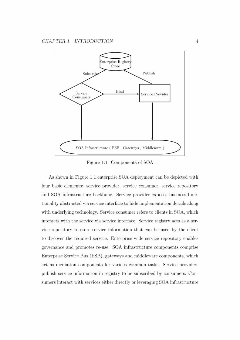
As shown in Figure 1.1 enterprise SOA deployment can be depicted with
four basic elements: service provider, service consumer, service repository
and SOA infrastructure backbone. Service provider exposes business func-
tionality abstracted via service interface to hide implementation details along
with underlying technology. Service consumer refers to clients in SOA, which
interacts with the service via service interface. Service registry acts as a ser-
vice repository to store service information that can be used by the client
to discover the required service. Enterprise wide service repository enables
governance and promotes re-use. SOA infrastructure components comprise
Enterprise Service Bus (ESB), gateways and middleware components, which
act as mediation components for various common tasks. Service providers
publish service information in registry to be subscribed by consumers. Con-
sumers interact with services either directly or leveraging SOA infrastructure
CHAPTER 1. INTRODUCTION 5
backbone .
SOA instantiates EA [5] with service-orientation for enterprises. Though
enterprises have now built their complete technological backbone using SOA,
aligning SOA with EA broadly requires realizing the vision of Service Ori-
ented Enterprise (SOE) as described in [6]. There is lot to achieve to real-
ize the vision of SOE. Recent advances in services driven business models,
agile delivery methodology, and distributed integration requirements have
reinforced attention on consumer-focused business operations and product
delivery using service-orientation. The maturity level and scope of service-
orientation requires delivering quality-aware adaptive service-oriented enter-
prise systems under the purview of these recent advances. This is an under-
lying motivation of this research. The next section details the motivation for
thesis
1.2 Motivation
For businesses to sustain it has become important that IT must support
them. All modern organizations serve many business needs with IT like
supply-chain management functions of receiving parts from supplier, supply-
ing goods, purchase order management, billing management. It caters to all
major business groups like sales, finance, human resource, accounting and
marketing. Overall job of IT is to provide an infrastructure to automate
business processes leveraging its capabilities. But there are challenges in
managing IT with growing business demands and synchronization of local
and global demands. It is not uncommon to see IT as a cost center. Enter-
prise systems had grown huge with ivory tower architectures to manage these
systems. Increased need of globalization, led by re-occurring economic crisis

CHAPTER 1. INTRODUCTION 6
has put lot of demands on IT to support agility, flexibility and simplicity.
IT needs to drive efficiency and ease the cross-enterprise and intra enterprise
business integration. Most importantly, it needs to be responsive and act as
a growth enabler of emerging business requirements. It is still a challenge
to build an IT system complying with these demands and is really being
realized hard and inadvertent to move IT from cost center to a value center.
Cost reduction and faster time-to-market are key requirements to stay com-
petitive. This leads to redundant infrastructure and increases overall cost of
IT management.
SOA by virtue of service-orientation enables organizational agility [7] by
aligning business with IT. Followed by its huge adoption at an application
level, scope of SOA is now changed to enterprise level (Service Oriented
Enterprise (SOE)) [8] as envisioned by EA. However not every application is
service-oriented.
Adoption of cloud computing [9] as services based business delivery model
is an innovation, which thrives on SOA. Enterprises have very well realized
that successful delivery of cloud based services require convergence [10] with
SOA. Without providing service-orientation, the conceptualization of Soft-
ware As a Service (SAAS), Platform As a Service (PAAS) and Infrastructure
as a Service (IAAS) in a virtual environment of cloud cannot be successful.
The integration of SOA and cloud opens the vast development space [11]
for measured and managed services delivery. This integration has long-term
impact of delivering on-demand service-orientation that can truly yield the
benefit of re-use, interoperability and flexible architecture.
Emergence of concept like ‘Internet of everything’ (IOT) have directed
researcher community for convergence on Internet and distributed comput-
ing [12] despite the type of client. Many of these connected objects on the

CHAPTER 1. INTRODUCTION 7
Internet will be resource limited devices. Employing SOA in such a case
cannot sustain without guaranteed QoS and on-time delivery. Discovery of
services and on-demand provisioning of missing functionality will be a sig-
nificant challenge in such a case. For instance, say a service running on a
physical device fails re-deployment. In such a case the discovery of a similar
service will be a possible option for running system to provide high availabil-
ity and not to impact consumer base. The next section discusses the research
questions in view of these recent advances and adoption of SOA.
1.2.1 Research Questions
The formal adoption of service-orientation began around 2006 with the re-
alization of standards like SOAP and WSDL [13]. The wave of adoption is
huge since then due to its sheer benefits and promising characteristics. The
true value of SOA is obtained, on services being shared across business units
and functional boundaries in an enterprise. Re-use of the same service cannot
be simply achieved by the onus of sharing it as a functional entity alone. In
fact, non-functional attributes play a very important role to enable proper
reuse. The de-facto standards for syntactic QoS-specification like WS-Policy
[14], UDDI [15] cannot support holistically the dynamic aspects of generic
QoS needs. Modern enterprises have the need for dynamic and run-time in-
tegration of services of different QoS-aware maturity level. The reason being
during this pragmatic adoption of SOA, they are in a heterogeneous state
with respect to QoS provisioning. For example:
• Legacy applications can be wrapped as services to fulfill operational
integration needs. The static or nil QoS specification mechanism can
serve the need of such services. These services cannot be tied with the

CHAPTER 1. INTRODUCTION 8
mainstream application to be a pool of common re-usable services.
• There are some services which are designed for internal or on-the-
premise usage during their inception. Dynamic QoS reporting could
not have been the criteria for these services at that time. These services
generally report QoS numbers based on load testing, static observations
or predictions to a centralized enterprise SOA registry.
• There can be some services using the common middleware such as
Enterprise Service Bus (ESB) for dynamic QoS management using me-
diation capabilities of ESB while others can use standalone way of
interaction.
The managed and measured delivery of services has become a minimal ex-
pectation and customers ask in recent times. It is also one of the essential
requirements of cloud computing. The services designed for on premise usage
can also become a part of off-the-shelf external application. Nevertheless, in-
ternal or external, this is the time when run-time aspects need to be seriously
considered to cope up with the increased need of agility and adaptation. The
way of exposing as well as managing services need to evolve to assure, confirm
and determine the non-functional aspects in a consistent manner coping with
the heterogeneity of QoS-aware maturity. However, it has two requirements:
1.) It demands services to be designed for re-usability with due consideration
of non-functional aspects.
2.) Redundancy management to allow consumers to choose the best services
adaptively based on all possible options. Considering the need of this evo-
lution, the overall focus requires building and managing re-usable services
in an agile manner with a QoS management consideration despite the var-
ied degree of maturity. A generic QoS-aware framework that can adapt to

CHAPTER 1. INTRODUCTION 9
this varied level of maturity requires consideration of both design time and
run-time aspects. The two key questions are raised to identify the problem
statement.
1. How to elicit and derive consistent set of prioritized func-
tional and non-functional requirements, explicit or implicit,
in a multi-stakeholder scenario?
A methodology that can provide a way to translate implicit and
explicit needs to requirements from disparate customer segments and
stakeholders would be an effective approach in such scenarios. The
same is detailed out as Blitz-CSOA (modified Blitz QFD [16]) explained
in Chapter 4 in the thesis. As part of this approach, two new scales
(normal and convex) have been defined for relative prioritization and
a decision matrix for bidirectional alignment between business and ar-
chitectural communities [17].
2. How to provide a consistent end user experience amidst chang-
ing eco-system (network characteristics, component service
cost and other QoS parameters) in an enterprise environment?
There is a need of a common framework for enterprise-wide
adoption, which adapts to these changing non-functional characteristics
leveraging self-management and feedback capabilities. The framework
is built in phases with Web Service Proximity Resolution Framework
(WS-PR) [18] (Chapter 5) and Domain Specific Language [19] (Chapter
6) developed as part of this work as an underlying foundation. Finally,
an adaptive framework has been developed as part of the thesis that

CHAPTER 1. INTRODUCTION 10
includes high-level domain specific language, QoS evaluation mecha-
nism and service selection algorithm (open-sourced in GitHub). The
framework is explained in detail along with results in Chapter 8.
Based on the questions above it is realized it is important for enterprises
to address the gaps to agile business needs that can be gained by fast and
adaptive IT. For businesses talking of ‘Services Everything’ an adaptive IT
is the realization of Service Oriented Enterprise (SOE). The next section
determines the research area mapping to the questions above with respect to
Service Development Cycle (SDC).
1.3 Research Objectives
Managing these diverse sets of recent advances in utility-based computing,
agile development methodology, proliferation and diverse integration require
adaptive quality aware SOA systems. The following gaps in enterprise SOA
deployments in Service Development Cycle[SDC] need to be addressed for
adaptive QoS aware SOA systems as listed below:
• Requirement Analysis
Agile development methodology yields functionally working chunks in
each cycle to its customers. This ensures lesser time to delivery for key
features. Since delivery cycles have become smaller it has become even
more important to ensure associated nonfunctional requirements. Gen-
erally, focus is on features delivery catering to functional requirements.
A formal methodology driving agile functional and non-functional re-
quirements with the collaboration of all relevant stakeholders will drive
customer success along in consensus with enterprise standards.

CHAPTER 1. INTRODUCTION 11
• Design
Designing SOA systems based on the requirements has become nat-
ural to enterprises to support its distributed nature. However huge
deployment and adoption of SOA has led to the proliferation of ser-
vices providing similar functionality with different QoS. Re-usability
and composability by their very virtue support agility as a SOA prin-
ciple. Redundant services need to be managed and controlled at an
enterprise level to yield maximum re-use and quality delivery. Enter-
prise Registry and design tools support static aspects of these design
patterns. There has been work done in dynamic discovery of redun-
dant services but adaptive behavior requires an autonomic QoS discov-
ery along with redundancy management framework. Without redun-
dancy management real advantage of controlling proliferation will not
be achieved.
• Development
Development phase till date was more focused on writing business logic
for applications. For developing quality aware adaptive SOA systems,
it is required to provide a mechanism for QoS assertions for both ser-
vice provider and consumer. Also communication among participating
entities should be for non-functional attributes need to be incorpo-
rated during development phase for all the participating entities. This
communication mechanism should be consistent for all SOA system en-
terprise wide, which will lead to wider adoption and interoperable QoS
aware SOA systems.
• Testing
CHAPTER 1. INTRODUCTION 12
This step is kept out of scope of this work.
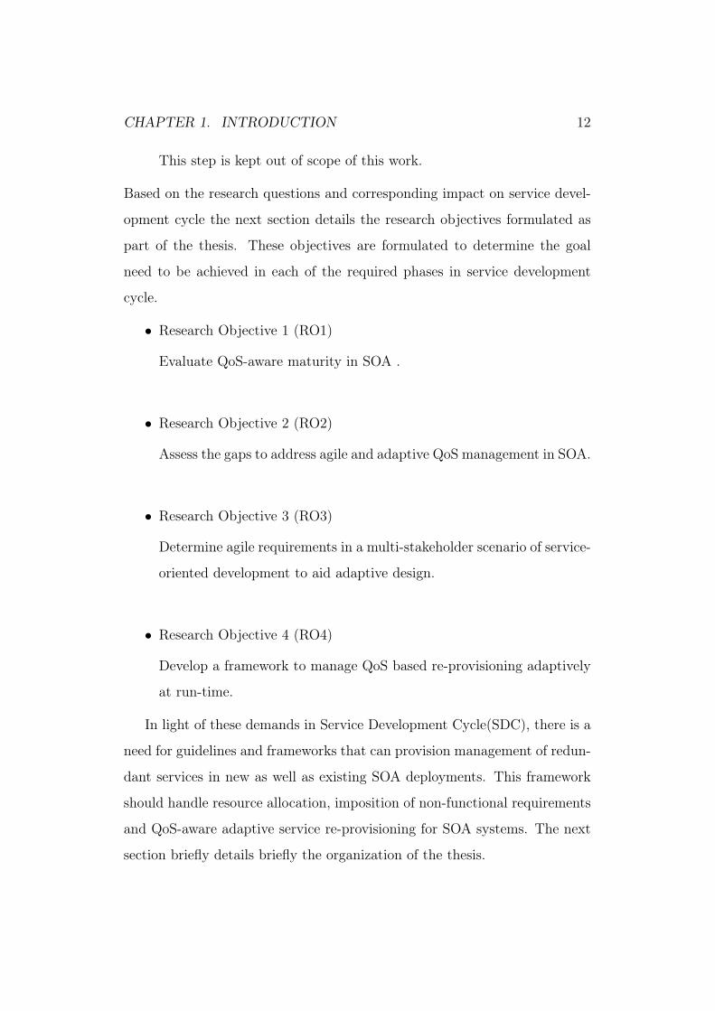
Based on the research questions and corresponding impact on service devel-
opment cycle the next section details the research objectives formulated as
part of the thesis. These objectives are formulated to determine the goal
need to be achieved in each of the required phases in service development
cycle.
• Research Objective 1 (RO1)
Evaluate QoS-aware maturity in SOA .
• Research Objective 2 (RO2)
Assess the gaps to address agile and adaptive QoS management in SOA.
• Research Objective 3 (RO3)
Determine agile requirements in a multi-stakeholder scenario of service-
oriented development to aid adaptive design.
• Research Objective 4 (RO4)
Develop a framework to manage QoS based re-provisioning adaptively
at run-time.
In light of these demands in Service Development Cycle(SDC), there is a
need for guidelines and frameworks that can provision management of redun-
dant services in new as well as existing SOA deployments. This framework
should handle resource allocation, imposition of non-functional requirements
and QoS-aware adaptive service re-provisioning for SOA systems. The next
section briefly details briefly the organization of the thesis.
CHAPTER 1. INTRODUCTION 13
1.4 Organization of the thesis
In this section, we would briefly look at the organization of this thesis. The
thesis is divided in multiple chapters as detailed below.
Chapter 1: Introduction
In this chapter, problem is briefly defined along with an overview of the
work done determining the layout of the thesis. The research questions
followed by research objectives are being shared to lead to the direction
of research.
Chapter 2: Background
As part of background, various foundational technologies like SOA,
cloud computing referred to in this work are explained. This chapter
explains the rationale for the profound need of adaptive QoS-aware
SOA systems in light of these recent advances.
Chapter 3: Review Work
This chapter reviews and analyzes the current state of the work in
Adaptive and Quality of Service in SOA domain across both require-
ments gathering and discovery phase.
Chapter 4: Agile SOA Methodology
This chapter explains in detail Blitz-CSOA methodology developed as
part of this work by modifying Blitz QFD approach for requirements
elicitation. Two new scales have been developed to determine the rel-
ative priority of the functional and non-functional requirements based
on time-to-capability and time-to-market needs. A new decision ma-
trix has been proposed to ensure prioritization based on bidirectional
alignment of stakeholders and architects.

CHAPTER 1. INTRODUCTION 14
Chapter 5: WebService Topological Selection
This chapter details the design of a new framework called Web Service
Proximity Resolution (WS-PR), which can carry out web service selec-
tion based on topological information of network. It describes a new
web service called Network Topological Information Service (NTIS),
that acts as a broker for service matchmaking and ranking. NTIS lever-
ages an existing Network Description Language [20] as a standard to
model enterprise network topology using Resource Description Frame-
work (RDF). The selection algorithm implemented as part of NTIS
uses network topology information of clients and server for ranking
and matchmaking based on proximity as QoS. The extended WSDL
for service uses WS-Policy for location metadata specification.
Chapter 6: DSL for WebService QoS Constraints
This chapter describes a new high-level language, that has been de-
veloped as part of this work. This language is a QoS domain specific
language (DSL) for Web Services. The syntax of the language is be-
ing kept closer to conceptual model of Web Service Modeling Ontology
(WSMO) to ensure interoperability with standards. It leverages the
syntax of writing DSL language in Groovy. An example has also been
provided. The source code shared in github demonstrates the imple-
mentation.
Chapter 7: QoS Aware Discovery Mechanism
Architectural Principles and framework for QoS-aware discovery are
defined in this chapter. The DSL and NTIS framework are brought
together to embed them in various discovery mechanisms based on the
QoS-aware maturity level of the SOA systems.
CHAPTER 1. INTRODUCTION 15
Chapter 8: Adaptive QoS-Aware Discovery Mechanism
This chapter explains in-depth the new adaptive discovery framework
developed in this work. The work described in Chapter 5 and 6 acted as
foundation to build this framework. The work done in Chapter 5 con-
siders proximity as the only criteria for service selection. It is extended
in this framework to include generic QoS for service selection. The
DSL designed in Chapter 6 acted as a common language for commu-
nication across the framework to express service characteristics, client
requirements, sharing feedback and response. A motivating example is
discussed in detail with a number of objective functions to explain the
system behaviour using the framework.
Chapter 9: Conclusion and Future work
This chapter summarizes the key contributions of the thesis. It lists
the scientific contributions arising out of this work. It establishes the
link of evaluation and contributions to research objectives. The scope
for future work has also been outlined.

Chapter 2
Background
2.1 Introduction
Software Systems have come a long way from standalone programs serving
automation of specific task to development of large enterprise systems. Enter-
prises have a structure determining the way in which it operates [21]. People,
processes, technologies and business scope determine this structure. With
re-occurring economic crisis success of an enterprise depends on its adapta-
tion to market-place agility and elastic business needs. Enterprise systems
have grown widely heterogeneous and diverse over a period of time embrac-
ing to diverse business needs. Thus adaptation is not a one-click operation,
it requires complex integration and interaction of business and technology
stakeholders to achieve a business goal based on the customer expectation.
Architecture lies at the heart of enabling this interaction and integra-
tion. It provides an abstraction for designing software systems based on the
interaction pattern of underlying components along with the relevant and
most appropriate positioning of these components. Distributed computing
architecture and technologies is the cornerstone to model globally distributed
16

CHAPTER 2. BACKGROUND 17
enterprise systems. The concept of distributed computing emerged way back
in 1980’s with Remote Procedure Call (RPC). Object orientation henceforth
became the mainstream programming methodology. In order to support dis-
tributed computing for objects standards Object Resource Broker (ORB)
emerged as a specification for inter object communication. Standards like
CORBA, COM/DCOM, and RMI emerged as an implementation of ORB.
The fine grained and tight coupling nature of object interaction and grow-
ing heterogeneity in enterprise applications gave birth to Service Oriented
Architecture as an architectural paradigm.
This chapter defines and explains the key concepts and technologies used
while building the motivation of the thesis. During the course of explaining
these concepts, it also sets the context and rationale of using them as part
of this work . It first defines Service Oriented Architecture (SOA), which
is the core concept in the thesis. It then discusses the relationship of SOA
with Enterprise Architecture (EA) and how SOA serves as an instantiation
of EA. Next it introduces the concepts of cloud computing and the need for
current enterprise deployments to converge to SOA. It then introduces Agile
methodology and the need for driving SOA using Agile methodology. All
these concepts and terms are detailed to establish the need to support en-
hanced quality needs for enterprise SOA systems not only to support growth
but also to consider the scope of service-orientation in view of these impact-
ing factors. The next section introduces the emergence of Service Oriented
Architecture.
CHAPTER 2. BACKGROUND 18
2.2 Service Oriented Architecture
Service Oriented Architecture (SOA) emerged as a paradigm to design and
integrate distributed systems by yielding vendor neutral technology inde-
pendent entities called services. It has formally emerged as an evolution
of the necessities and realizations of varied inter-related concepts combin-
ing disciplines of distributed computing, middleware, database systems, pro-
gramming languages [22]. Operationalization of open source standards like
Web Service Description Language (WSDL) [23] and SOAP [24] in 2001 was
benefited by the emergence of a concept called ’Web Services’. Web Service
[25] introduced the concept of exposing functionalities as services rather than
components or modules. Service itself is a very important concept in SOA. It
is an autonomous, self-contained well-defined independent entities described
by service interface . It is not as fine-grained as functions and objects but
enough coarse-grained to represent an atomic function. Self-contained and
autonomous nature of services provides the capability to compose them into
applications representing complex business process leveraging existing and
new technologies. Though Web Service is one of the most successful im-
plementation of SOA, it is not the only implementation. Technologies like
CORBA, EJB [26], and Apache Thrift [27] are other standards that are used
for scalable cross-language services development. Emergence of open source
frameworks and technologies promote cross-language and platform interac-
tion of heterogeneous environments leading to pioneering job of making SOA
real.
Over a period of time enterprises have become heterogeneous. Enter-
prises acquired varied application and technology stack to serve their current
and future needs. They witness adoption and dissemination of technology
CHAPTER 2. BACKGROUND 19
stacks, programming methodologies and industry standards. There is also a
wealth of useful code in legacy applications that remains despite the dissem-
ination and evolution. Re-inventing or developing applications from scratch
is a very cost intensive solution. Integration in a vendor neutral and technol-
ogy independent manner with a loosely coupled and sustainable and stable
architecture is the need to solve the problem. This need for homogeneity
and harmony is the top-down requirement as well. Business-IT alignment is
one of the top managerial concerns since 1994. “Business-IT alignment” and
“Speed and Agility” are among the top issues for IT executives as pointed
out by Luftman [28] explained the in MIS quarterly executive report.
"applying IT in an appropriate and timely way, in harmony with
business strategies, goals and needs" is a strategic business asset.."
IBM CIO survey in 2006 [29] also reflected the inadvertent need and re-
sults of enterprises to align business goals with IT.
"Organizations that effectively integrated business and technology
insight delivered greater financial results in terms of revenue growth
and operating margin."
SOA provides the means of achieving organizational agility. It provides
flexibility and means of alignment of business adaptation in execution of
modern-day businesses. Organizational restructuring, dissemination and adop-
tion of new platforms and technologies are common way to stay competitive
and meet business requirements. SOA, by virtue of service-orientation, pro-
vides an abstraction to design systems using business process and technol-
ogy agnostic entities called services. These services are used across business
groups and boundaries independent of ownership. It provides a capability
to respond fast to business needs. Another virtue of SOA is to provide the
CHAPTER 2. BACKGROUND 20
capability of embracing new and existing technologies. It serves the need to
integrate existing and new applications even if they are on different technol-
ogy stacks and platforms. The buzzwords around SOA entered into main-
stream application design and integration in 2006. It aligns business and
technology in a way to allow wrapping legacy applications as services. Busi-
ness IT alignment and its capability of adaptation with respect to existing
and new technologies and platforms are the key drivers for SOA adoption.
Though SOA started with focus on technology to develop applications as a
bunch of services deployed across an enterprise. This wide adoption of SOA
had to be recognized at an enterprise level to gain consistency and visibility
at all appropriate level. As service started growing over enterprise network
the need for management and governance arose at an enterprise level. SOA
governance formally emerged as a standard body in many enterprises. SOA
governance has henceforth existed as formal mechanism to ensure the same.
Not only that one of the key benefits of this governed mechanism can be
to create or increase injection points in the system to achieve the required
results. That means with changing business dynamics and recent trends gov-
ernance can be a useful mechanism to ensure the new and key requirements.
SOA governance emerged as a necessity of it. It becomes important to align
it with the overall Enterprise Architecture and governance to a SOA view
point and understand the relationship between the two.
The scope of service-orientation nowadays transmits to all levels includ-
ing strategic, business operation model, technological, infrastructure and de-
ployment.Recent advances in utility-based business models realized by cloud
computing, short product development lifecycle driven by agile methodology,
and diverse integration needs for Internet of Things (IoT) require renewed
focus on enterprise system SOA deployments. In view of this, impact and

CHAPTER 2. BACKGROUND 21
urgency of QoS-aware design and adaptive management of SOA services has
been studied as part of this work. Next section details the industry overview
of aligning EA with SOA followed by the discussion on these recent trends
an impact on the same on service-orientation.
2.3 Aligning SOA with EA
EA is key to the success of organization, but it requires proper engineer-
ing and enforcement across the enterprise. EA is realized with common
frameworks as TOGAF[30], Zachman[31]. It can be represented by various
views based on the specifics of enterprise stakeholders. SOA instantiates EA
with service orientation. EA should have services and process view to sup-
port SOA. Figure 1.1 shows the alignment with EA. Aligning SOA with
EA yields benefit of avoiding services sprawl, reuse and enhanced business
agility, end-to-end visibility and ease of implementing change as explained
below:
• Systematic growth
Huge adoption of SOA may lead to ”not so required” or unnecessary
services on an enterprise network. It need to be realized ‘Not everything
should be wrapped into services’.
• Governance
With EA governance bodies in place, SOA governance teams can be
a subset of these teams. They can work in sync with EA governance
for service management and role of adherence to align business policies
with requirements of service-orientation .
• Ease of implementing change

CHAPTER 2. BACKGROUND 22
SOA systems can be designed to leverage end-to-end view provided by
EA from strategy to implementation.
• Consistent Quality
Leveraging EA product and systems helps in alignment with strategy
and organizations business practices. The underlying processes are
linked to performance measures, which ensures consistent in quality
delivery.
Gartner made a strategic assumption in 2008 [32]
"By 2011, 30 % of organizations will be remediating and re-
fining their SOA services to be driven by EA processes and frame-
works , with a focus on EA”
Gaining consistent quality requires governance that enforces design method-
ologies and principles enterprise-wide. Dynamics of organizational structure
determines communication pattern among different business groups.
EA and SOA both share common goals of aligning business strategy and
its corresponding execution in alignment with policies, processes and perfor-
mance measures of organization. SOA should leverage EA to categorically
deliver service oriented capabilities and align its role with vision and strategy
of enterprise. Without unification, they will lead to entering into an era of
service silos while solving the issue of application silos. Realizing it, many
standard bodies and institutes have formalized this alignment. Also there
are various works studying this alignment.
Aligning SOA with EA supports conceptualization of Service Oriented
Enterprise (SOE) as envisaged in [8]. SOE view of service-orientation has
a larger scope than development of services. Enterprises are still hybrid in

CHAPTER 2. BACKGROUND 23
nature due to existing operational business requirements. Enterprises have
become enough mature in SOA realization. The pragmatic approach to
service-orientation [33] was the viable option for enterprises for successful
SOA strategy. However various dimensions were added and impacted the
view of service-orientation. Recent advances in cloud computing, Internet
of Things (IoT) are the trends impacting business models and integration
needs of enterprises. Agile development methodology is a common approach
for enterprise application development. All these recent trends and adoption
development methodologies have impacted SOA . They have added dimen-
sions to the way SOA can be and should be adopted and implemented within
organizations. Next section details the understanding and relationship of
cloud computing with SOA.
2.4 Cloud Computing
Cloud computing as an advancement of utility computing thrives on service-
orientation. It has changed the business models conceptualization from op-
erations based delivery to service orientation delivery model. The definition
of cloud computing as provided by National Institute of Standards and Tech-
nology (NIST) [34] is as follows
Cloud computing is a model for enabling ubiquitous, convenient,
on-demand network access to a shared pool of configurable comput-
ing resources (e.g., networks, servers, storage, applications, and
services) that can be rapidly provisioned and released with mini-
mal management effort or service provider interaction.
Cloud computing, is an innovation that thrives on SOA and efficient

CHAPTER 2. BACKGROUND 24
utilization of distributed infrastructure and resources to provide exhaustive
computing resources. Cloud computing provides these capabilities as ser-
vices. These services are managed in a virtualized environment. Flexibility,
scalability and elasticity are the key characteristics of cloud. There are three
important variations in cloud computing stack.
Platform As a Service
As the name suggests it provides a platform on which software can be
developed and deployed. It provides clients the necessary operating
system, hardware and server processing, data bases of the platform. A
typical PAAS capability within an organization creates a vanilla soft-
ware stack with necessary standardized components. The key benefit
is re-use in terms of infrastructure processing and standardization of
platform software technologies.
Software As A Service
This model has evolved with the move of service providers to the cloud.
Earlier called utility computing this actually means that the required
application and software is offered by services providers to be used by
end user. This software is managed and deployed at service providers
site.
Infrastructure As A Service
In this model, the cloud offers virtualized hardware with services for
create, maintenance and recovery for the same. This is the most prim-
itive form of cloud computing with most flexibility and control. At
the same time due to lack of higher order services and platform, it can
become very cumbersome to develop and maintain.

CHAPTER 2. BACKGROUND 25
Enterprises have very well realized that successful delivery of cloud-based
deployment requires convergence with SOA [33]. Enterprise systems can
either leverage cloud computing services offered by other enterprise providers
or they can have a cloud computing backbone for the same.
The key characteristics of cloud computing is its stack and business de-
livery model. Offering infrastructure, software and platform as a service to
consumers requires a quality driven measured approach. The purpose of
cloud computing from a business delivery model is to provide self-service
model to elastic resources. The allocation of these resources will be changed
dynamically based on consumer needs. The consumer expects the delivery of
declared service level agreement (SLA) for its services . These offerings are
offered on payment model and are ideally metered and billed based on usage.
Traditional enterprise SOA deployments were mostly servicing the internal
needs of organizations. These deployments could sustain and were built upon
on static-driven and declared QoS. The consumer oriented business model of
cloud computing extends service orientation to the business model but it can
no longer work traditionally based on static SLA.
An incremental and iterative development methodology known as "Agile
development" is a popular approach among many organizations for software
development. It challenges the traditional project development approach
adopted by many companies to deliver software products. It supports in-
cremental development of software with each iteration building on top of
previous iteration and development cycle. Contrary to traditional develop-
ment methodology, that requires a lot of emphasis on lot of analysis and
product development vision during the initial phases. Next section details
about Agile development methodology
CHAPTER 2. BACKGROUND 26
2.5 Agile Methodology
Agile development approach has gained a lot of popularity in software de-
velopment. It supports unpredictability in consumer demands as well as any
blocking issues during design and development to be addressed. The model
works with gathering agile set of requirements for an iterative manner. Agile
manifesto delivers some key capabilities that mostly get ignored in traditional
development methodology.
The ten principles listed by Agile Manifesto explain the reason of its
wide popularity. As a methodology, it promotes and entails involvement of
key stakeholders in the system. Continuous feedback from customer and key
stakeholders in the systems provides the key benefit of consumer satisfaction.
Another key benefit of Agile is self-organizing team based obtained from and
resulting in well-defined skill set . This methodology empowers customers
and key stakeholders to contribute to product development by providing their
feedback ,suggestions or contribution to design.
SOA is an architectural style while agile is a development methodology.
Though they serve different purposes they have common goal from the busi-
ness perspective that is "agility”. Enterprises are now operating in Agile
model. Driving SOA adoption using agile methodology is an opportunity to
drive integration and development of services in an agile manner. By na-
ture services serve different functionality and generally owned by functional
groups. Architecture is key to SOA to look forward to future state of services
integration and client interaction. Too much focus on long term architecture
may conflict with the strategy of agile. Driving SOA development in an agile
manner has been addressed, studied, suggested as well as practiced by many
authors in different ways. It is observed that while unifying SOA develop-

CHAPTER 2. BACKGROUND 27
ment with agile development methodology, the focus is on functional design
of services and integration of the disparate services delivery.
Driving SOA using agile methodology requires addressing three main
challenges. One is dealing with complexity of SOA design and development
activities (issues like resolving conflicts for assigning roles for functionally
different services owned by different functional groups). Another one is how
to ensure quality while building a complex system using agile methodol-
ogy. First challenge is resolved in different ways by many organizations
and already SOA applications are delivered in an agile development man-
ner. However implementing adaptively Service Oriented Architecture using
Agile methods considering non-functional aspects is an open area. In the
next chapter, we would look at existing works and current state of research
both in the area of Adaptive design and discovery based on non-functional
properties. And How it gets buried in the issues dealing with complexities,
conflicts resolution and role assignment for the application.
2.6 Summary
This chapter discussed the background leading to the rationale of conducting
this research. It is realized that the traditional way of enterprises offering
static SLA and QoS parameters for SOA services will no longer be success-
ful. The fast and adaptive IT response to business needs is one of the key
requirements of enterprises. The recent trends in industry corresponding to
Agile development methodology for SOA development can result in a reac-
tive behavior. At the same time it may not provide high quality systems, be-
cause they do not imply each other. The non-functional aspects are equally
important for the successful agile SOA execution. The run-time reactive-
CHAPTER 2. BACKGROUND 28
ness for SOA systems is seen as adaptation corresponding to dynamic and
run-time changes due to end-user preferences or pre-defined requirements.
With the huge proliferation of services adaptive discovery mechanisms be-
come important to discover the service based on the differentiating criteria
of non-functional aspects. Next chapter reviews the works in these areas to
understand the gaps and viable contributions that need to be made for design
time and run-time needs for QoS-aware SOA systems.
"A great wind is blowing and that gives you either imagination or a
headache."
Catherine the Great

Chapter 3
Review Work
3.1 Introduction
Marketplace agility and dynamic business needs require organizations to re-
spond rapidly and cost effectively to business demands. SOA provides an
architectural solution to model heterogeneous and complex integration prob-
lems using flexible and loosely-coupled interaction of services. The services
in SOA are designed to be reusable and composable units that can be used
across varied applications. A service-oriented application is no longer a self-
contained world. It involves communication of services via interfaces in-
dependent of underlying technology. ‘Agility to Adapt’ is one of the key
benefits of enterprise SOA adoption obtained by hiding the complexity and
intricacies of implementation behind interfaces. Real-world SOA integration
models complex enterprise systems and applications using simplified inter-
face communication mechanism hiding the complexity. The huge adoption
of SOA has led enterprises to get reformed to shared service center. In an
enterprise scenario a flexible business process can be obtained by selecting
from the set of services available from a shared service repository. The cur-
29

CHAPTER 3. REVIEW WORK 30
rent state of enterprise applications support dynamic service-orientation. As
a next step enterprises need to provision adaptive SOA to step beyond the
regular predictable behavior modeling of dynamic systems and processes.
The adaptation requires providing autonomous behavior to exhibit adaptive
properties [35].
Figure 3.1 shows the phases of SOA solution stack maturity growth in an
enterprise both in terms of services and Quality of Service (QoS) progression.
As described below it can be denoted using four levels:
Figure 3.1: SOA stack
• [Basic Services:] First phase of SOA adoption begins with basic ser-
vice capabilities. These services should be enough coarse-grained to
represent foundational capabilities of an organization. QoS at basic
services layer means individual service quality characteristics.
• [Composite Services:] This layer represents composite application,
which can leverage basic services layer to aggregate and orchestrate

CHAPTER 3. REVIEW WORK 31
composite application. A business process can leverage composite ser-
vices as well as basic services to represent clinical business functions.
Quality at this layer means composite QoS determined by each indi-
vidual service in the chain or composition.
• [Dynamically reconfigurable Services:] Dynamic reconfigurabil-
ity has become a necessity to evolve SOA to a phase where services can
re-configure themselves based on run-time requirements. This capabil-
ity takes care of a predictive un-required behavior in reaction to fault.
Dynamically changing QoS characteristics need to be monitored as well
updated to predict and decide reconfigurability. Dynamic selection and
invocation of service has recently been studied a lot and has become
very important.
• [Adaptive SOA:] Next logical step is Adaptive SOA. It subsumes dy-
namic behavior along with self* [36] properties to act on un-predictable
run-time error or performance behavior. To attain self* behavior de-
manded by adaptive systems non-functional properties need to be adap-
tively managed both at design time and run-time. It also requires QoS
attributes to be specified at each individual service level to determine
QoS for composite SOA application.
Enterprise business capability model need to be extended to support
adaptation. The layer at the top demands research to support adaptive
growth of service-orientation within enterprise. The research plane of SOA
systems as depicted by Papalozou et al. [37] describes research roadmap for

CHAPTER 3. REVIEW WORK 32
different layers in the SOA stack. It is realized that the conventional software
development methodologies do not address the interface design, re-usability,
composability adaptively. The grand challenges in monitoring and manage-
ment layer identified the need of adaptive service management capabilities.
The research agenda described by Software Engineering Institute [38] and
[39] emphasized the need of evolution of existing SOA deployments to cater
to design-time and run-time adaptation. QoS is pervasive [Sikri and Gell
2014] to the complete SOA research plane. Consistent user experience need
to be provided beyond network boundaries, devices and accessibility. Qual-
ity is paramount for any modern day business service offering and business
process execution. While identifying the adaptation needs non-functional
properties are considered as a paramount requirement for SOA systems. It is
needed to support the recent developments in industry like Agile development
methodology, that requires SOA applications to support adaptive design to
accommodate unpredictable changes. The rapid deployment of SOA need
to adaptively scale to support discovery of a unique service that fulfills it
requirement amidst the multiple functionally similar services available on an
enterprise network. These services offer similar functionality but different
QoS. The two key areas in SOA life cycle that are of paramount importance
are adaptive design and discovery based on non-functional properties. The
review work in this chapter focuses on these two areas. The next section de-
scribes the review works supporting Agile and Adaptive SOA development.
It is followed by another section that focuses on review works for QoS-aware
discovery mechanism.

CHAPTER 3. REVIEW WORK 33
3.2 Agile and Adaptive SOA
Successful design is one of the key success criteria for stable and adapt-
able [40] distributed application. SOA is an approach to model distributed
application integration using services. In order to achieve adaptation it
is suggested to use [41] iterative software development framework to de-
velop service-oriented systems. Agile development methodology is the re-
cent trend for consumer-driven, iterative development. It promotes faster
time-to-market, time to delivery and adaptive design and development ca-
pability. Figure 3.2 shows the typical iterative cycle in Agile methodology.
These methodologies are both iterative and incremental. The iterative pro-
cess makes progress through successive refinement based on early and fre-
quent feedback in agile methodologies. It is an incremental process as each
deliverable in agile methodology represents a subset of functionality that is
built on previous one. Each iteration results in an incremental deliverable
subjected to stakeholder review. The backlog represents the prioritized set
of requirements that are being picked in iterations to deliver incremental
functionality.
Roa
dMap
Requirements
Deliverab
le
Backlog
Iteration
Iteration
Iterat
ion
Daily Review
Feedback
Figure 3.2: Agile Methodology
CHAPTER 3. REVIEW WORK 34
The benefits of SOA were very well foreseen, leading to its wave of adop-
tion in 2005 and trough of disillusionment [42] in 2006. Currently both SOA
and agile development methodology are in the Plateau of Productivity in
Gartner’s curve. SOA supports organizational agility by virtue of service-
orientation. Sustainable development and delivery [43] despite changing re-
quirements in an adaptive manner is the primary reason of agility in Agile
development methodology. There are two important points to be highlighted
here: Agile methodology and SOA share the same goals but they are not de-
rived from or imply each other. Secondly Architecture and development
methodology are not at odds. It is required to align them in a way, to lever-
age the benefit of agility with the execution of Agile principles that can take
advantage of modular and loosely-coupled architecture capabilities of SOA.
In order to provide an inherent support for faster time to delivery, time-to-
market, and consumer-driven design and development of SOA system agile
methodology is an inadvertent need. Having said that, grass rooted and
fundamental requirements need be considered, to see how to align them to
achieve the maximum benefit. As discussed below these requirements include
the foreseen challenges that need to be addressed for a distributed and global
service-oriented integration in an enterprise environment.
• People orientation vs Process orientation: Agile is more people-
oriented and less process-oriented. Face-to-face communication, stake-
holder review, continuous feedbacks considers people-orientation from
requirement analysis to design decisions to delivery and development.
For small scale and simple integrations it may work. However for com-
plex enterprise systems process-orientation is required for better main-
tainability and to avoid any disruptive design decisions and changes
that can affect the future evolution. modeling
CHAPTER 3. REVIEW WORK 35
• Complexity vs Agile principles: Considering the fact that SOA
models complex distributed systems, the impact of change will be per-
vasive as well as costly. Therefore design is key to service-orientation.
On the other hand Agile is about incremental delivery of continuous
backlog of features welcoming changing requirements in the middle of
development. SOA models complex distributed integration that are
not very small in size. In order to support such agility it is required to
adaptively design SOA systems.
• Ownership: From an enterprise perspective different services owner-
ship in a single SOA application can be spread across multiple business
units that have different priorities. It is imperative to bring these mul-
tiple stakeholders to consensus with different priorities. Many of these
stakeholders may not even be aware of the impact the services make at
the end user level. Hence it is not simply important to prioritize the
customer requirements but enable collaborative SOA design identifying
the key stakeholders impacting the system.
• Modeling of customer requirements: One of the primary areas of
study in agile methodology is requirements engineering more specifi-
cally for large and complex distributed systems. It is even said that
Agile and requirements engineering are not compatible and Agile meth-
ods are ideally suited for systems supporting adaptive development
[44] rather than predictive development. However for large and com-
plex projects [45] requirements’ modeling is required to support future
growth despite development methodology. Also the modeling of cus-
tomer requirements needs to capture the current as well as future state
• Non-functional requirements in Agile: The customer satisfaction

CHAPTER 3. REVIEW WORK 36
actually entails by fulfilling its needs. Needs is mainly the manifestation
of non-functional requirements. Agile does not mandate and talk about
non-functional requirements (NFRs). It is even said that they are ill-
defined in Agile methods. NFRs are important mandatory for complex
SOA system design. For Agile delivery of adaptive requirements NFRs
are a reflection of customer needs. This requires planning and focus on
key design attributes early in the SOA life cycle.
Considering the above factors there are works in literature addressing
them in different ways. It is realized [46] agile methods are difficult to scale
for large and complex projects due to lack of planning and focus on early
delivery of result. One key aspect in planning is requirements engineering.
Quality is directly impacted by the kind of requirements engineering prac-
tices adopted. Requirements engineering for traditional and Agile develop-
ment methodologies are not compatible [47]. Unlike traditional requirement
engineering (RE) practice of freezing the requirements before development
begins, agile welcomes the changing requirements during the course of it-
erations. There is no exhaustive documentation and contract agreement in
agile. Agile contracts are a characteristic that is being discussed these days.
Elssamadisy [48] discussed that some practices of agile methodologies (with
XP as an agile approach) such as iterative development, frequent testing
and feedback, small release, and refactoring, are suitable for large projects.
However others like standing-meetings, use of metaphors to describe system
architectures, factors like informal design discussion meetings and making
assumptions about the architecture can become topsy-turvy for distributed
and large scale projects.
The commonalities and differences in traditional requirements engineer-
ing and agile software development approaches are discussed in [44]. The RE
CHAPTER 3. REVIEW WORK 37
approach used for traditional development can be described using following
main activities: elicitation, analysis, negotiation and documentation. The re-
quirement elicitation is about discovering requirements based on the context
based information, interviews, design approaches, use cases, focus groups,
brainstorming and prototyping. These are different types of collaboration
techniques in requirements elicitation. Once requirements are captured, next
step in requirement analysis is conflict resolution and prioritization. Require-
ments documentation followed by validation of this document is used further
for requirements management. Customer involvement is crucial for RE in
both traditional approaches and agile methods and is considered an impor-
tant aspect for project success. In traditional approaches, the customer is
mainly involved in initial phases whereas Agile emphasizes on continuous cus-
tomer collaboration throughout the development cycle. Authors have high-
lighted that non-functional requirements are ill-defined in agile approaches.
The agile development mainly focuses on functional aspects reflected as fea-
tures delivery. The study also expressed that most non-functional require-
ments need to consider in the development phase itself because it affects
the design and technology decisions. This work specifically identifies the
need for agile methods to consider and deal with NFRs in agile development
methodology.
Cao et al. [49] in 2004 provided a tailored agile method (XP) approach
for large-scale projects. Authors did point out lack of guidance using agile
methods for large and complex projects and demonstrated the applicability
of XP as an agile approach for it. The tailoring included upfront-deign, sur-
rogate customer engagement, flexible pair programming, short release cycles
with layered approach, re-use with forward refactoring. A case study has
been shared demonstrating the applicability of agile methodology for an ap-

CHAPTER 3. REVIEW WORK 38
plication development in large software development organization FinApp.
FinApp is involved in the development of a complex enterprise system that
provides financial services to banks, insurance companies, loans and bro-
kerages. The application to be redesigned is huge. Beyond the size, the
application involved corporate cash management, which is a very complex
domain. Security is critical and quality is the focus of development effort.
There were two main reasons for FinApp to choose XP as a tailored agile
method. First was the understanding that agility is required to accommodate
evolving requirements. Secondly solely relying on formal communication in
Agile methodology causes problem in bringing different stakeholders at a for-
mal consensus. It also becomes challenging to communicate the requirements
to the development team. Designing upfront is seen as one of the key require-
ments for large-scale and complex projects in enterprise systems. Enterprises
have a structure determining the way in which it operates. Enterprise soft-
ware systems fulfill the need for managing business by using an information
flow between different business verticals: finance, accounting, supply chain,
customer information and sales. The integration among these channels is
nowadays performed using SOA that enables the information flow using a
simplified technology agnostic interface based service-oriented design. The
services are designed for maximum re-use in an enterprise to leverage an ex-
isting functionality across the board consistently to avoid business silos and
re-inventing the wheel. Authors also expressed the need of tailoring more
specifically needed for the reason that they are dealing with enterprise sys-
tems. In the words of project manager at FinApp:
“The difference is what we got here is an enterprise application
and that is what drive everything. We have an extremely modified

CHAPTER 3. REVIEW WORK 39
version of XP exactly because we have enterprise application”. in
the words of one the project managers in FinApp.
Architecture and design is key for enterprise SOA development not only
because of the fact that it models complex systems. It also nails down to the
fact that the overall design is important for distributed system modeling. As
the systems grow in complexity [49] a big picture of the overall project [50] is
required to align it with enterprise quality standards. Too many stakeholders
can dismantle the communication of the key features need to be achieved by
the developers. The challenge is reflected by FinApp manager as:
“It is found that without an overall design, it is difficult to maintain
a big picture of the project as the systems grows. The communi-
cation between developers is also problematic when a large number
of stakeholders are included.”
Most of the enterprise systems business logic can be designed using pat-
tern based design promoted by SOA. In turn re-use is promoted by pattern-
based design of SOA. ‘Forward Refactoring’ of existing features is suggested
by FinApp to enable adaptive design for future requirements by reusing ex-
isting code base.
Benefiled [51] shared his experience for Agile adoption in a large enter-
prise Yahoo. Author has put forth real-time challenges faced due to high
competitiveness faced by the organizations. He exemplifies his experiences
in getting product to market quickly, staying flexible and adaptive to change
leading to the need of Agile and Lean software development process. Yahoo
supports around 800 million active internet users worldwide. Agile journey

CHAPTER 3. REVIEW WORK 40
in Yahoo began in 2004 by the convincing presentation from Jeff Sutherland
[43].Peter Demer, the VP of product development that time was given the
budget and mandate to lead the effort ‘grounds up’ to ensure agile adoption
within the company. The company chose the path of grounds up adoption
rather than top-down mandate to study the real need of Agile. The adop-
tion started with the coaching of Scrum for various teams with continuous
follow ups and surveys. The survey results indicated that 77 percent had
positive feedback about using Scrum, 68 percent found that Scrum reduced
the amount of time wasted, 64 percent of respondents believe that Scrum im-
proved the business value of their product at the thirty-day mark. Within a
one-year mark twenty-five teams started using Scrum with 84 percent of team
members supporting this new Agile method. The ongoing feedback helped
in capturing the motivation of the team for Scrum adoption. The number
of teams using Scrum increased from 4 to 40 within next year realizing the
evident benefits of adoption. Architecture is not key to Agile. But contin-
uous collaboration and meetings helped Yahoo! mail team unravel major
architectural issues early in the life cycle to fix them before launch. This led
them respond to a major competitive threat during the development phase.
They released a major storage improvement ahead of schedule, saving the
company millions of dollars. The positivity and adaptability exhibited by
the development team at Yahoo was one of the major reasons for smooth
transition to Agile resulting in its adoption. Design had always been key in
large organizations and same is the case with Yahoo. They have a separate
design team that is heavily consumer focused and involve user experience
experts, UI designers. The Scrum teams worked hard to address their con-
cerns and build a common ground. Continuous refactoring and evolutionary
design was at odds with the existing design team culture. As part of this

CHAPTER 3. REVIEW WORK 41
effort it became a practice for design teams to come find common ground as
else consumer focus will get deprioritized.
Lucia and Qusef [52] have discussed how requirements engineering tech-
niques can be combined with agile methods. This study provides guidelines
on how requirement engineering can be mapped to different agile methods.
The authors have given their views on Agile RE by mapping traditional RE
practices to XP and Scrum agile methods. Prioritization of requirements is
done based on understanding of product owners and business collaboration
with customers. The user stories in XP and product backlog in scrum are
used for requirement elicitation. Face-to-face communication and collabora-
tion is the replacement of exhaustive documentation in Agile. Authors have
mapped traditional RE phases with RE practice in Agile methods by mod-
ifying it with the addition of feasibility study phase. The feasibility phase
conducts an analysis of whether or not the target system is worthwhile based
on organizational objective. The key guidelines for RE in agile environment
is provided with the emphasis on key stakeholders identification.
Architecture and design is very important for real-world distributed en-
terprise application. Service Oriented Enterprise, Services of Everything and
Services of Anything are the direction and vision for enterprises to stay ag-
ile, competitive and ahead of the curve. IT needs to tie in and support
business in a way to yield agility in this move. In this highly competitive en-
vironment handling agility with respect to dynamic consumer requirements
require architects to have an adaptive futuristic view to system design. As
system grows with these dynamic consumer needs requiring delivery in con-
stricted time frame it is difficult to ignore the role of architecture and design.
Along with the focus on overall picture and end goal it is important to cap-
ture the consumer needs (related to satisfaction) to yield a quality product.
CHAPTER 3. REVIEW WORK 42
Agile development expect a continuous backlog of features to enable unin-
terrupted iterations and development. A distributed SOA application would
require capturing these requirements by doing the prior work of planning
based on roadmap and requirements. This should result in building this
catalog of agile requirements that helps in adaptive and agile development.
Most of the works theoretically discusses issues and provide guidance and
best practices to address them while practicing Agile methodology in dis-
tributed or complex scenarios. The review addresses the key issues and gaps
that need to be addressed in the areas of Agile Requirement Elicitation in-
cluding Requirement engineering, non-functional requirements, stakeholder
identification and formalization. A mechanism that can formally establish
this connection of customer needs with required set of stakeholders will help
in adaptive development with agile set of requirements.
Prioritization of requirements is realized as a vexing issue in SOA sys-
tems to address requirements engineering practice for SOA systems. The
formalization need to address the issue of collaborative design, stakeholder
management, non-functional requirements and alignment of technical gover-
nance aspects with enterprise governance and customer needs. The proposed
solution and formalized methodology is developed as part of this thesis to
address the gaps. The methodology is being explained in detail in next chap-
ter. The next section reviews works in understanding the state of QoS-aware
discovery approaches in SOA systems to formalize the gaps that need to be
addressed.
CHAPTER 3. REVIEW WORK 43
3.3 QoS-aware discovery mechanisms
Diverse integration needs for SOA, metering and billing based services deliv-
ery model can only be successfully delivered based on measured quality at-
tributes. Traditional SOA deployments for enterprises were mainly internal
and statically monitored. However enterprises have stepped ahead to under-
stand the need for dynamic service-orientation. Discovery is the huge and
rapid adoption of SOA has enticed lot of attention on discovery approaches.
It is common to see multiple services providing similar functionality on the
enterprise network. Reuse and replication are two use cases to provide better
quality. With the existing infrastructure well suited to their SOA application
requirements, enterprises require all of their systems to adopt a QoS-aware
management and discovery mechanism. With shared services registry de-
ployed in an enterprise, redundant services management and deployment is
the first step to build dynamic and adaptive QoS-aware service discovery that
can serve the varied consumer needs. There are works in literature address-
ing QoS-aware discovery at different levels. These works are studied as part
of this review to form an understanding of the current state and gaps that
need to be addressed. It is realized during the pragmatic journey in SOA
adoption, there is a shift in the use of standards from syntactic to semantic.
This transition also mostly aligns with the time during this journey.
If the discovery approach and QoS specification mechanism is leverag-
ing syntactic standards, it is termed as ‘Syntactic SOA’. The standard dis-
covery architecture for SOA systems comprises interaction among the key
components of SOA architecture i.e: consumer, provider and service registry.
WSDL [13] is a W3C recommendation for web service specification. It pro-
vides a structured mechanism (XML) to describe web services. A WSDL

CHAPTER 3. REVIEW WORK 44
structure consists of two parts: one part represents abstract operations and
messages. The other part concretely binds it to network protocol and mes-
sage format. The WSDL structure provides elements data types and message
structure definitions supported by the service and operations indicating pos-
sible actions like one-way, request response along with input and output for-
mat. All this information enable clients to access the syntactic information
they need to interact with the service. The elements of WSDL do not provide
mechanism to specify QoS attributes and associated information. Universal
Description Discovery and Integration (UDDI) [15] is the registry specifica-
tion for SOA systems. It provides a mechanism to publish service providers
discovery metadata that can be subscribed by service customers to discover
the services. The UDDI data model consists of four main components:
businessService: Offers description of a service.
businessEntity: Offers information about a provider that publishes the ser-
vice.
bindingTemplate: Represents the service technical details, including a ref-
erence to the service programmatic interface or API.
tModel: Represents the interface, classification information and namespaces
to add meaning to the UDDI data structure.
The default UDDI specification does not describe a mechanism to represent
non-functional attributes. Standard bodies like OASIS [53] has recommended
extending existing data structure UDDI tModel to represent QoS related in-
formation. WS-Policy [14] is a standard framework that provides mechanism
for service provider to specify policies representing QoS information provided
by them. It also allows consumers to specify their requirements with policy

CHAPTER 3. REVIEW WORK 45
assertions. The information provided in WS-Policy gets mapped to limited
ability for expressing many characteristics and attributes. Not every pos-
sible expression can be represented using policy assertions, such as request
parameters range, security domain specification, consumer capabilities [54]
and dynamic QoS attributes. Efforts have been made to extend WS-Policy
in various dimensions, to leverage its capabilities for QoS specifications.
There are set of standards that add semantics to the specification and
corresponding protocols and specifications to reason with them. ‘Semantic
SOA’ got its origination from ‘Semantic Web’ that was envisioned by Tim
Berners-Lee in 2001 [55] as an extension to the World Wide Web (WWW).
Ontologies are the backbone to provide semantics. It describes artifacts, their
properties and relationships in a knowledge domain. It empowers Semantic
Web Services (SWS) to allow consumers to express their requirements for
services rather than how to ask for them. The semantic markup enabled in-
formation can be used to create a knowledge base on the information obtained
from different sources. These semantically enabled service descriptions are
interpreted by the software systems presented by the providers and clients
to discover the desired service. Consumers can use the information pub-
lished in semantic descriptions to reach out to the service provider, though
their detailed interfaces may differ. We refer to such a service-orientation
as ‘Semantic SOA’. The standards in Syntactic SOA and Semantic SOA do
not provide comprehensive support for QoS. These standards have been ex-
tended in many works to provide QoS-aware discovery. The review work has
classified as shown in Figure 3.3.
As indicated Syntactic QoS-aware discovery mechanism mainly involves
extending syntactic standards like Web Service Description Language (WSDL)
[13], UDDI [15] and WS-Policy [14] majorly to address QoS specification and

CHAPTER 3. REVIEW WORK 46
Qos-baseddiscoverymechanism
Syntatic
ExtendingUDDI
ExtendingWS-
Policy
ExtendingWSDL
Semantic OWL-Sextension
WSMOextension
Agentbased
dicovery
Figure 3.3: Classification of QoS-aware discovery approaches
discovery needs. Similarly Semantic QoS-aware discovery extends semantic
standards, such as OWL-S [56] and WSMO [57]. A separate classification
has been provided to address the work done for multi-Agent based approach
based architectural framework Semantic Web Service Architecture (SWSA)
[58], specially designed for semantic web service discovery. The classifica-
tion aids in systematic research. The review also analyzes the feasibility of
these approaches in a real-world enterprise environment. To further gener-
alize this study also provides an architectural evolution of these discovery
approaches. It is realized that a QoS-aware discovery mechanism has two
major requirements:
[QoS Specification:]
This requirement involves determination of how and where to spec-
ify QoS requirements. ’How’ involves the characterization of QoS at-
tributes based on domain, capabilities and relationship. ’Where’ de-
termines the components that require QoS attributes to be specified.
’How’ is largely taken care of by extending WSDL and WS-Policy for
syntactic discovery approaches. For semantic descriptions ontologies
such as OWL-Q [59], QoSOnt [60], onQoS [61], QoS-MO [62], WSMO-
QoS [63], and WS-QoSOnto [64] are designed in many works to enable

CHAPTER 3. REVIEW WORK 47
QoS-aware specification. ’Where’ is generally being taken care by ex-
tending UDDI.
[Discovery approach:]
This step characterizes the matchmaking and ranking methodology em-
ployed in the service discovery mechanism. It utilizes the QoS specifi-
cation approach to provide a mechanism and steps for QoS discovery.
Most of the approaches discover services based first on the functional
requirements, followed by QoS characteristics.
Next section describes the works leveraging Syntactic QoS-aware discovery
and analysis of its gaps and adoption in an enterprise environment.
3.4 Syntactic QoS-aware discovery
The basic flow in discovery architecture involves three basic components
and the interaction between them: service provider, consumer and registry.
The discovery mechanism is characterized by aiding consumers to select the
unique service out of multiple services available on the network. The mecha-
nism to select this unique service varies based on standards, QoS specification
mechanism, selection and discovery algorithm. To provide interoperability
most authors have extended the existing standards UDDI, WSDL and WS-
Policy specifications to cater to generic QoS specification and discovery. The
next section describes works that have achieved the same by extending UDDI.
3.4.1 Extending UDDI
The benefits of SOA were very well foreseen, leading to its wave of adoption
in 2005 and trough of disillusionment [42] in 2006. The global and diverse

CHAPTER 3. REVIEW WORK 48
nature of organizations with predicted large-scale growth of service-oriented
applications would require usage of many registries. In that case, there would
be a need for infrastructure to support the specification as well as discovery
from federated registries. A QoS-aware extension to UDDI [65] was proposed
using UX based on network characteristics. The network model is abstracted
into domains, based on QoS characteristics, such as bandwidth, latency and
congestion. The UX system has four main components: the service requester,
local UDDI registry, UX server and Test Host. The QoS broker component
in the service requester reports its observed QoS to the reporter component.
The Test Host generates the QoS reports for local registered services because
it may not be possible to predict service performance in all cases. The UX
server receives an inquiry from the requester and processes it based on QoS
reports information available and its interaction with the local UDDI reg-
istry. Using a federated discovery mechanism promotes scalability and avoids
synchronization issues such as replication. The authors, in this case, used
federated discovery based on network capabilities. We noticed that until this
time, QoS-aware discovery was still in the early stages of determining how to
specify QoS. It was in 2005 that Serhani et al. [66] introduced the concept of
verification of QoS information using a verifier component. This information
was represented in extended UDDI, termed UDDIe. A broker component is
added to interact with both the service provider and consumer. As a first
step, the service provider interacts with UDDIe to subscribe to the broker
information. It then requests that the broker verify the QoS information
before publishing it in registry. A WSDL parser is used to extract functional
and QoS information from WSDL. QoS verification is performed by a set
of test cases and includes the verification of a fixed set of QoS attributes
based on the network and bandwidth. The result of verification is stored in a
CHAPTER 3. REVIEW WORK 49
database. Based on the claim made by the provider and the results returned
by the verification process, the web service is classified as bronze, silver or
gold. Once the verification is complete, the provider is awarded a certificate,
which is stored in the broker to confirm the verification. The verification pro-
cess requires a fairly in-depth validation of the syntactical attributes, which
would require accessing providers implementation. This may not be prac-
tical all the time, since service providers platform and implementation may
not even be accessible. Fixed set of QoS parameters are being captured and
tested using java implementation and SOAP handler.
Many works extend the default UDDI and its APIs for QoS-related infor-
mation, and the work done in [67] extends UDDI with an extra component
known as QoS Registry. The reference to the business and technical context
of the information in the QoS registry, is stored in UDDI. This add-on com-
ponent holds, specifically, the QoS information from service providers. It also
verifies the QoS information at the time of registration, with no considera-
tion of any run-time or dynamic changes in QoS information. It is observed,
that two levels of indirections for the QoS registry will incur extra cost for
deployment and management. This work is primarily focused on extending
UDDI to provision QoS information and does not focus on discovery aspects.
To further evolve the discovery mechanism to the next level, verification
based on client feedback was realized to be important, as studied in [68].
The authors have used the mechanism of a reputation score. UDDI was
extended to represent QoS information in keyedReference for the tModel
data structure in UDDI as suggested by OASIS. The ranking of services is
determined by a reputation manager, which assigns reputation scores to web
services based on the feedback received from the clients. A discovery agent
receives service requests and discovers the service based on client QoS and
CHAPTER 3. REVIEW WORK 50
reputation requirements. There are many representative works in reputation
based ranking of web services in SOA. The above works did not discuss the
specification mechanism of QoS attributes by the service provider, but there
is an assumption that providers will need to somehow provide QoS details to
UDDI, and that clients can specify their QoS goals, which will be analyzed
and processed by the broker on behalf of clients.
With the wide adoption of SOA, the dynamic business scope and large-
scale growth witnessed by organizations require federated QoS-aware dis-
covery was required.YE et al. [69] proposed a QoS-aware model for Web
Services discovery using QoS brokers for federated discovery. QoS attributes
are categorized on the basis of computational behavior, business behavior and
metadata restriction. The QoS broker is the main component in the architec-
ture, resulting in distributed discovery. It discovers the service by interacting
with distributed QoS brokers in the system, when sufficient information is
not available in the local UDDI registry. It also filters and merges the results
from different QoS brokers. The authors have not provided results or the
implementation of the proposed architecture. The next section details works
extending WS-Policy to serve specialized needs for QoS specification.
3.4.2 Extending WS-Policy
WS-Policy [70] became a W3C recommendation in 2007. WS-Policy is a
metadata specification. It emerged as a standard way to describe web service
properties using policies. Policies are a set of assertions that can represent
both functional and non-functional aspects. There are many aspects of non-
functional specifications that cannot be expressed using the standard WS-
Policy framework.
Diego and Maria [71] extended WS-Policy and the UDDI information

CHAPTER 3. REVIEW WORK 51
model, along with its APIs, to provide a framework for QoS-based discov-
ery. WS-Policy has been extended to include a QoS policy by referring to
the QoS information model. tModel in UDDI is extended to specify QoS
characteristics along with the capability to refer to the WS-Policy structure
for storing QoS policies. The UDDI APIs for publication, subscription and
inquiry sets have been modified for QoS-aware discovery. The broker com-
ponent interacts with the consumer, extended UDDI registry and service
provider to provide the required service to the consumer. First a list of func-
tionally similar services is found followed by the intersecting QoS policies of
these services. Intersection is determined by policy and attributes compati-
bility. The monitoring component intercepts between services and consumers
to monitor changing QoS attributes and communicate updated QoS infor-
mation to the broker. The broker in turn updates the same in the UDDI
registry. This work has demonstrated an extension to WS-Policy via QoS
information model representing QoS Policy. However, to support such an
extension, changes must be made in the UDDI tModel structure along with
its APIs. Representation of individual QoS characteristics can be modeled
using an information model, but time-based management of individual QoS
attributes cannot be provided using WS-Policy.
WS-temporal Policy [72] defines an extension to WS-Policy to offer time-
based constraints. A validity period attribute has been provided for each
policy attribute by using add-on characteristics for the attributes related to
time, including duration, start time, end time and expiration. The life cycle
management of these policies is performed using Temporal Run Time En-
gine (TPRE). The implementation of TPRE is done using Axis 1.4 [73] as a
SOAP-based framework, with the actions defined in XML schema. The client
side implementation is done using callback handlers of the axis framework.

CHAPTER 3. REVIEW WORK 52
This work enables a service developer to attach a validity period to the prop-
erties described in WS-Policy, but not at the services level. Business owners
adore SOA [74] because of its capability to align business and IT. Theoret-
ically, it sounds great, but it requires a mechanism to include the business
view of policies. The WS-Policy4MASC language [75] has been designed to
define business metrics along with conflict resolution strategies to return the
maximum value for autonomic running systems. New policy assertions have
been added to promote business-driven metrics. These new assertions do not
address the issue of dynamic attributes and are more focused on business
scope.
Web services are identified using an endpoint as specified by WSDL. The
Web Service proximity resolution framework proposed an extension to the
[18] WS-Policy framework to represent a location policy that can represent
and identify web services and consumers using a topological endpoint uri.
A Network Topological Information Service (NTIS) is used as a broker to
discover and rank services. The discovery mechanism implemented in NTIS
uses topological metadata that representing network topology to determine
the service ranking. Clients interact with UDDI to obtain the service location
and send this information to NTIS. NTIS determines the ranking of services
based on the proximity and topological location of consumers. This work is
further extended in [76] to adaptively discover services based on generic QoS
requirements of clients apart from proximity. Because WS-Policy does not
provide inclusive support for QoS, many authors have also extended WSDL
separately to represent QoS information. The next section details works
extending WSDL

CHAPTER 3. REVIEW WORK 53
3.4.3 Extending WSDL
D’Ambrogio, A. [77] defined Q-WSDL to represent QoS properties using a
meta-model extension to WSDL based on the principles of Model Driven
Architecture (MDA). The extended meta-model is represented using classes
and associations for Q-WSDL. The transformation from WSDL meta-model
to extended QoS metamodel is inspired by standard UML profiles from OMG
[78].This meta-model is translated into XML documents to represent Q-
WSDL XML documents. However, the authors did not address advanced
QoS management features and suggested that users utilize available standard
languages, such as WSLA, in such a manner that the existing design would
not be impacted. A meta-model extension to WSDL is also suggested in [79]
to describe non-functional attributes of services and properties of physical
objects based on MDA. The representation of physical objects as services is
done to achieve requirements of web service integration for the Internet of
Things. The meta-model extension is implemented by transforming UML
models and XML documents, resulting in WSDL representations of physical
objects to ensure the mapping between physical objects and the web service.
This extension is not applicable to complicated objects that require multiple
factors to represent them. In addition to meta-model modification, authors
have adopted an approach to modify the schema or adding a new namespace
to the existing WSDL specifications.
. WSDL is extended in [80] by adding criteria as a non-functional prop-
erty, to express client intent of attributes apart from functional characteris-
tics. The extended WSDL is known as X-WSDL. A new namespace has been
added to represent the attribute criteria. A new Inquiry API has been added,
to search the service based on this element. QoS-aware discovery and spec-
CHAPTER 3. REVIEW WORK 54
ification is also performed using particular frameworks, such as HP’s Web
Services Management Framework (WSMF) [81]. WSMF has addressed web
services management aspects such as advertisement, description and assign-
ing web services at different QoS levels. IBM’s Web Service Level Agreement
(WSLA) is another framework [82] for specifying, negotiating and monitor-
ing service level agreements (SLAs) in web services interactions. The next
section analyzes the pros and cons as well as the feasibility of leveraging
syntactical discovery implementations in real-world enterprise environments.
3.4.4 Syntactic discovery in enterprise scenarios
Figure 3.4 depicts a generic QoS-aware discovery architecture in syntactic
SOA. The figure describes the extension mechanism employed in a UDDI
registry, WSDL and WS-Policy for QoS specification in syntactic SOA. The
broker component is used in many works to mediate and serve the needs
of QoS discovery. UDDI extensions generally involve tModel extensions.
tModel can be extended to represent static QoS information by reference to
a static WS-Policy file, an extended QoS registry reference, and a QoS policy
file that may not be necessarily WS-Policy compliant or extended WSDL for
QoS specification. This QoS-enriched information is provided to the UDDI
registry by either the service provider, a monitoring component or a broker.
To trust the broker, the certifier and verifier components are used to first
verify the information and then certify it using a certificate authority. These
components can be used when there is a requirement for a trusted broker.
Table 3.1 summarizes all of the works that we have discussed on QoS-aware
syntactic SOA discovery based on UDDI, WSDL or WS-Policy extension.
Many authors have used a broker component for processing consumer
requests and interacting with publishers. The broker introduces multiple

CHAPTER 3. REVIEW WORK 55
Service Broker
Extended Registry
Verfiercomponent
Certifiercomponent
QoS Monitoringfor dynamicattributes
Client ServiceProvider
tModel ->QoS Pol-icy file
(static/dynamic)
extended byQoS-Registry
(static)
tModel ->WS-Policy file
(static)
tModel ->QoS info
publication(static)
ExtendedQoS-awareWSDL(static)
QoS enriched ser-vice publication
Binding
find_bindingtModel request
QoS Metris
Figure 3.4: Architecture for QoS discovery in syntactic SOA
Table 3.1: Classical SOA Spec
SpecificationMechanism
[83] [65] [67] [72] [75] [71] [18] [77] [79] [80]
ExtendingUDDI
Y Y Y
ExtendingWS-Policy
Y Y Y Y
ExtendingWSDL
Y Y Y Y
CHAPTER 3. REVIEW WORK 56
levels of indirections resulting in a higher complexity of the system because
all services in the eco-system must adopt it. The reliability and trustwor-
thiness of the broker must also be controlled and managed. The presence of
a broker interface in the UDDIe registry limits its adoption for large scale
services, internet services and external clients. The need for a broker arises
for dynamic QoS attributes, negotiation, billing, validation, and certification,
which means that the functionality is beyond the capabilities of existing com-
ponents of syntactic SOA .
Serhani et al. [66] used the broker for the verification, certification, QoS
negotiation, monitoring and adaptation processes that the components of
syntactic SOA cannot handle. The broker architecture proposed by them
is more suitable to telecom, finance and billing-related applications, where
clients need to stay up-to-date in real-time via adaptation, negotiation and re-
negotiation to ensure the QoS provided. In this case, the broker ensures the
QoS provided and billing takes place accordingly. Similarly in [18], NTIS acts
a broker component. It not only acts as a central repository for enterprise-
wide topological metadata but also determines the rank of services leveraging
the metadata information. The QoS broker described in [69] provides spe-
cialized functionality of distributed federated discovery. With these types
of specific requirements, the broker architecture provides a viable option to
cater to specific use-case and it becomes unavoidable to use these multiple
levels of indirections.
Some authors have modified UDDI by extending the API or custom
tModel references. The approach of extending UDDI [71] provokes chal-
lenges in the implementation of the organizational set up because it intends

CHAPTER 3. REVIEW WORK 57
to change the behavior of the well-published server. Some companies may
even use an external UDDI vendor who will not change APIs. The tModel
extension approach is recommended because it does not involve changing
APIs but, at the same time creates a complex metadata that must be under-
stood by all components participating in the architecture. Modification of
the UDDI registry must be a controlled mechanism that considers the service
management aspects of versioning, service identification, and inter-domain
and business-related QoS attributes that cannot be ignored.
SOA is no longer about SOAP implementation. Leveraging SOAP mes-
sages to provide run-time QoS information as in [83] and [72] may not be
applicable for all enterprise services. SOAP is the de facto for B2B services
and external transactions, but this may not hold true for other architectural
standards for Web services, such as REST and implementation specifications,
such as EJB and Apache thrift [27] which are very common in enterprise sce-
narios.
For dynamic and run-time QoS attributes, a monitoring component has
been provided in some of these studies to monitor and capture run-time QoS
information. To store and update these run-time values, a few authors have
used UDDI, policy files or some type of repository or database. Updating
UDDI for run-time attributes as in [71] is not a recommended solution be-
cause its core purpose is to act as a central repository for enterprise services.
Run-time attributes should be calculated and updated separately [18] and
should not impact the virtue of UDDI to act as an enterprise service repos-
itory. The enterprise service repository (UDDI registry) is an important
component for the SOA governance process and is, for all practical purposes,
static and read-only. This governance process permits services to be pub-
lished in the registry based on the feedback provided by the SOA architect

CHAPTER 3. REVIEW WORK 58
and enterprise governance stakeholders. The services are permitted to be
published in the registry only if they prove to be compliant with the enter-
prise security and infrastructure requirements. The service provider must
be specific about the QoS provided the service and the value delivered by
lending this service to the enterprise network. Thus, dynamic writing ca-
pability in UDDI will make the enterprise-wide registry slow, unmanageable
and inconsistent.
If an organization has multiple private registries across different domains,
business verticals or business units, federated discovery will play a key role
within enterprise registries. QoS-aware federated discovery mechanisms as
described in [65] [69] require determining the service ranking of similar ser-
vices or services complaint with QoS goals, across multiple registries. How-
ever, federation requires multiple levels of trust, hence, discovery across dif-
ferent enterprise registries will be a challenge because of security, audit and
compliance issues.
The policy assertion mechanism provided by WS-Policy is not complete
in regard to catering to dynamic QoS attributes and is limited in expressibil-
ity. The efforts made by extending WS-Policy and WSDL [72], [75] act as
significant motivation to provide different characteristics and types of QoS
attributes, but none of them are standardized to meet real-time adoption.
Multiple versions of policies and WSDL definitions with different extension
mechanisms have created interoperability issues while addressing QoS. Any
adoption of these extensions should be governed at an enterprise level to
maintain consistency and interoperability. WSDL extension [80] will not
serve for QoS attributes specification. The meta-model extension to WSDL
[77], [79] would primarily change the classes and interaction that would im-
pact all of the entities participating in the system. It would be difficult

CHAPTER 3. REVIEW WORK 59
to support dynamic changes in QoS characteristics. For this, a QoS meta-
model’s changes need to be scalable enough to consider all aspects of client re-
quirements. WSDL being a syntactic specification, QoS specification should
not be merged with the interface description. The separation would benefit
from exposing the same interface with different QoS attributes. It would also
provide flexibility for using different QoS model specifications for the same
WSDL interface. Hence, it is recommended to keep functional descriptions
separate from interface descriptions. In a specific case of the least dynamic
QoS requirements, WSDL can be extended but may not be consistent for
enterprise-level adoption. The next section details QoS-aware discovery in
Semantic SOA.
3.5 QoS-aware discovery in Semantic SOA
Similar to syntactic SOA, semantic SOA discovery mechanisms have two
major requirements:
QoS Specification: WSMO and OWL-S are two core ontology specifica-
tions for semantic SOA, but neither of them addresses QoS specifi-
cation comprehensively. As a result many ontologies such as OWl-Q
[59], QoSOnt [60], onQoS [61], QoS-MO [62], WSMO-QoS [63], and
WS-QoSOnto [64] have been developed.
Discovery approach: To address QoS-based discovery, there is need to
map QoS descriptions to the expressions that can represent QoS of-
fers and goals. QoS offers depict the capabilities of the services, and
QoS goals model the client requirements. The reasoning mechanism
and discovery approach should be able to solve these expressions to

CHAPTER 3. REVIEW WORK 60
yield a list of ranked or best services.
The next section details works extending OWL-S and discovery approaches
based on it.
3.5.1 Extending OWL-S
OWL-S is an upper ontology based on Web Ontology Language (OWL). In
syntactic SOA, UDDI allows for a classification- and keyword-based search
mechanism. Using OWL-S also allows, capability-based search in addition
to classification-based discovery, but these searches provide only functional
discovery. An upper ontology, OWL-Q was developed by Kritkos et al. [84],
as part of a thesis to describe QoS parameters. A matching algorithm [59]
has been developed to infer the equivalence of two QoS metrics descriptions
defined using OWL-Q. It does this by specifying three rules, with the last
rule either simplifying the difference between two mathematical expressions
using a mathematical engine or resulting in the solution of a constraint sat-
isfaction problem (CSP). Both of these mechanisms can work in parallel. It
does not provide utility support in its ontologies for quality, priority or rec-
ommendation for flexibility for attribute flexibility.
Ma and Wang [85] defined a QoS-aware discovery framework for Semantic
Web services. The framework uses a three-layered approach for the entire
discovery process. The first layer performs semantic matchmaking. This
layer applies the Description Logic (DL) reasoning based on the proposed
QoS ontology. The DL reasoning, can only guarantee the compatibility of
the request with the advertisement. As a second step, QoS conditions are
translated into mathematical expressions, representing constraints that are

CHAPTER 3. REVIEW WORK 61
then solved using constraint programming (CP). The third layer selects the
best service by weighting each possibility by the priority of the QoS require-
ment determined by the value of the data tendency. Data Tendency is a
predefined value that represents user expectation on the QoS attribute val-
ues. For example, in this study, the authors defined the tendency as High,
if the client wishes the values to be as large as possible and Low if as low as
possible. The authors defined the tendency as Given, if the parameter is as
close as possible to a given range and as NullTendency if it cannot be clearly
determined. The authors implemented a prototype and shared experimental
data based on price and availability as QoS attributes. The next section
explains works extending WSMO
3.5.2 Extending WSMO
Wang, Vitvar et al. [86] described a QoS ontology based on WSMO along
with a selection model. QoS attributes are classified as either static or dy-
namic. The selection algorithm works in two steps. The first processing
step involves normalization of the matrix, reflecting the quality requirement
matrix and quality values of candidate services based on the maximum and
minimum value of each quality metric. The second step is ‘uniformity anal-
ysis’, based on the value of a specific QoS metric to determine the relative
evaluation of each service’s QoS.
A high-level Domain Specific Language (DSL) is implemented in [19] by ex-
tending WSMO. The work in [87] uses the language defined in [19] to describe
two discovery mechanisms: ‘Blind Belief’ and ‘Measured QoS Assertion’. In
Blind Belief, the client blindly believes the QoS assertions declared during
the services during bootstrap. The approach aids in quick adoption by legacy
CHAPTER 3. REVIEW WORK 62
applications without re-writing but may not be suitable for the needs of dy-
namic QoS management. However, in Measured QoS Assertion discovery, all
interaction in the system occurs through an enterprise service bus (ESB) that
acts as a communication backbone for the measurement of QoS attributes.
These approaches can be adopted pragmatically based on the QoS maturity
level [88] of an enterprise. The authors have also used standard multi-agent-
based architecture for QoS-aware discovery as defined in Semantic Web Ser-
vices Architecture (SWSA). These works will also use QoS ontologies that
may extend WSMO or OWL-S. For brevity, we have classified such works
using an agent-based discovery mechanism, as described in the next section.
3.5.3 Agent-based discovery
The Semantic Web Services Architecture (SWSA) committee established a
set of architectural and protocol abstractions [89] for publishing and discover-
ing semantic web services using agents. It is based on the W3C Web Services
Architecture, with the combined vision of the OWL-S consortium and the
WSMO group. It also leverages standard ontologies for service description.
Hence, services can be built using any of the standards, such as OWL-S and
WSMO along with an enhanced QoS ontology to specify the QoS informa-
tion. The key aspect of SWSA is the interaction among agents with different
roles and specializations to communicate and provide automatic discovery
for web services.
The Foundation of Physical Agents (FIPA) [90] provides standards for
agents and multi-agent systems (MAS) to promote the interoperability of
heterogeneous agents and the services represented by them. It provides the
use of agent management system (AMS), Message Transport Service (MTS)
and Directory Facilitator (DF) to manage MAS. Every agent needs to reg-

CHAPTER 3. REVIEW WORK 63
ister with AMS, which controls the access to and use of the agent platform
along with nomenclature. MTS provides a transportation layer for inter- and
intra-agent communication among agent platforms using the Agent Commu-
nication Language(ACL). The Directory Facilitator (DF) provides agents
with the capability to register and query their services with the DF. FIPA
was actually not meant for semantic web services. It has been extended in
most of the works to provide semantic discovery to provide interoperability
with agent standards.
Gumus and Grucan et al. [91] used SWSA for semantic web services
discovery. The authors proposed a broker agent that acts as an intermedi-
ary to perform all of the agents interaction tasks i.e., negotiation, mediation
and matchmaking, for the consumer via a requester agent in Multi-Agent
Systems (MAS). The overall infrastructure consists of four ontology agents,
i.e., an agent to interact with the ontology repository and knowledge base, a
service provider agent for service providers, a requester agent for consumers
and a broker agent for all other mediation tasks. Services are described us-
ing WSMO and interact with the service provider agent using SOAP. ACL is
used for inter-agent communication. FIPA provides a brokering Interaction
Protocol for agents, but it is not suitable for semantic services. In this case,
the authors extended the brokering agent with a protocol with more inputs
and QoS parameters. It has enhanced FIPA for semantic services, though
QoS has not been a part of the study, except for its consideration in the
brokering protocol .
SQoSWSAF Architecture is defined in [92] for QoS-based semantic web
services discovery. A service broker retrieves a service on behalf of the con-
CHAPTER 3. REVIEW WORK 64
sumer. A reasoning agent interacts with the OWL-parser, knowledge base
and inference to reason and return the desired web service based on the re-
quest message. The authors suggested a planning agent for each domain
that refers to its generic plan. The request from the consumer is routed to a
specific planning agent with the help of an Intelligent Assistant Agent(IAA),
which uses the local knowledge base to route the request to the required plan-
ning agent. The authors proposed a robust architecture to cater to multiple
domains, but service specification is always assumed to be based on OWL-S
and an assumed QoS ontology. There is no mention of an inter-agent com-
munication channel or any standard specification for agent interaction. Next,
we discuss and come to understand the challenges and gaps in semantic QoS-
aware discovery mechanisms along with architectural characterization.
3.5.4 Semantic Discovery in Enterprise Scenarios
Figure 3.5 represents a generic architectural framework encompassing se-
mantic web service discovery using a service provider, consumer and registry.
The publishing manager acts as the service provider to provide a semanti-
cally enriched service description and publishes it in the service registry. A
component acting as a discovery manager performs matchmaking and rank-
ing on the interaction with a reasoning mechanism, knowledge base and QoS
database, as required, to return the result to the client. ExtendedWSMO and
OWL-S, representing the QoS ontology, are used for service descriptions. The
Resource Description Framework (RDF) [93] provides the capability to merge
more than one ontology, even if the underlying schemas differ. The discovery
mechanism of semantic Web Services broadly uses the concept of Degree of
Matching (DOM) to determine the ranking. DOM determines the similar-

CHAPTER 3. REVIEW WORK 65
ity of two entities based on similarity metrics. The matchmaking approach
adopted in semantic discovery can be categorized as capabilities matching,
logic-based, similarity-based and graph matching. Capability matching refers
to semantic capability matching that performs description logic (DL) sub-
sumption between inputs and outputs or service classification. Logic-based
reasoning uses DL subsumption matching, where reasoners create an ontol-
ogy tree and determine the DOM along with the knowledge base. However,
using only logic-based reasoning may not return correct results each time.
The use of similarity measures and information retrieval techniques serve as
better reasoning mechanisms. Another approach is graph-based where each
service is represented by a directed-acyclic graph (DAG). In this case struc-
tural matching of graphs and existing graph matching algorithms are used
for matchmaking.
Discovery Manager
Service Registry (se-mantically enhanced)
ServiceProvide
r
Reasoning
Mecha
nism
WSMO
OWL-S
RDF
Input/OutputSub-
sumption
Multi-levelMatching
DL-matching
Graph-based
Matching
ConstraintProgram-ming
OntologyKnowl-
edge Base
QOSDatabase
Figure 3.5: Current Mechanism of QoS-aware discovery in semantic SOA
The growing needs of dynamism and adaptation require enterprises to

CHAPTER 3. REVIEW WORK 66
Table 3.2: Specification mechanisms for QoS in semantic SOA
Specification Mecha-nism
[84] [85] [92] [86] [94] [19]
Extending OWL-S Y Y Y
Extending WSMO Y Y Y
move from syntax towards semantics. Improving operational efficiency can
no longer provide sustainability and profit to organizations. The diverse
portfolio of applications, services, business scope, globalization and virtual-
ization has increased the complexity of products and systems. Thus, the
knowledge base of an organization relies on a large number of heterogeneous
data sources. The data in these data sources can be structured or unstruc-
tured. Accounting, sales, products, services, and ERP data are structured
data, whereas data in emails, text, audio, and images are generally unstruc-
tured. Syntactic standards can no longer successfully integrate these dis-
parate sources and data silos to support dynamically integrated processes
or applications. A much more abstract level of knowledge management is
required to turn information in these data sources into knowledge that can
be shared across enterprises. Enterprise taxonomy is one of the ways in
which communication uses categorizations and common terms. However, it
has its limitations in resolving dynamic conflicts for similar data sources.
Semantic integration using ontology-directed metadata extraction will help
disambiguate and link heterogeneous data sources with correct and auto-
mated discovery mechanisms and integration. The use of ontologies also
opens the door for organizations to move from a closed-world model to open-
world model to integrate with external applications and other enterprises.
From an IT perspective, various systems, such as human resources, product

CHAPTER 3. REVIEW WORK 67
ordering, and finance, have domain knowledge that can be modeled using on-
tologies. The most important job of IT is to deliver agility to achieve business
functions. Modeling both structured and unstructured data using ontologies
provides a common structure for domain knowledge. This information not
only is useful for integration but also has strategic imperatives. Intelligent
data analytics and prediction are some of the visible benefits to using se-
mantics. SOA discovery, integration and composition will be most benefited
due to the addition of semantics to information. The standard discovery and
reasoning mechanisms comprise many frameworks, such as Jena. However,
description logic is not sufficient to address QoS-aware discovery involving
complex constraints and relationships. For example, expressions such as Re-
sponseTime <1ms represent QoS constraints that cannot be solved using
Description Logic. With the existing tools, standards and reasoning mecha-
nisms, QoS-based discovery can be successfully achieved as a hybrid of DL
and Constraint programming’s along with the well-defined methodology to
map specifications to QoS constraints. Constraint programming two most
important requirements to provide a comprehensive solution is as follows.
1 A transparent mechanism to map QoS descriptions to expressions repre-
senting constraints.
2 If constraint programming is used, a satisfiable CSP is required to solve
these constraints.
However there are gaps in the manner in which constraint programming
is used for semantic QoS-based discovery. Benbemou et al. [95] have used
their own mechanism to axiomatically describe semantic web services. There
CHAPTER 3. REVIEW WORK 68
is a reference to specifying QoS characteristics in service descriptions to rep-
resent constraints, but details of the service descriptions are not available.
Additionally, there is no mention of CSP to solve these constraints. Without
using CSP, it may not be possible to solve these constraints. Kritikos et al.
[96] described OWL-Q as an ontology for QoS descriptions. They have used a
rule-based semantic matchmaking algorithm for discovery, but details of the
mapping of descriptions to constraints are not available. Wang et al. [94]
presented a QoS ontology by extending WSMO. Their published approach
does not detail the matchmaking mechanism. They have also provided a
selection algorithm using normalization, but this resolution is not specific to
QoS discovery because it is not clear on how the ontology is being leveraged
for constraints mapping. From an implementation perspective, it may not
be possible to provide a decision at run-time for every CSP in every use case.
Such use cases will need to be dealt with at design-time.
The generic QoS ontology as proposed by Ma and Wang [85] may not
be interoperable with all of the existing standards. The authors themselves
made assumptions about terms with reference to ontology while matching
requests with advertisements, for example, while matching syntactic aspects
of QoS. We have discussed the provision of QoS specifications as constraints
and the reasoning mechanisms based on constraint programming to solve
them. Issues such as distributed discovery and automation are prominent re-
quirement of modern-day businesses. An agent-based architecture is another
approach formally adopted in industry to formalize discovery for Semantic-
based Web Services.
SWSA provides a standardized choice for distributed coordination dis-
CHAPTER 3. REVIEW WORK 69
covery, but standards around agents for semantic web services have yet to
propel. There is work going on to extend FIPA standards to semantic web
services. We have realized that the solution to addressing QoS in a Multi
Agent Environment (MAE) is primarily modeling agent interactions model-
ing and QoS modeling and matchmaking with the ultimate goal of optimiz-
ing distributed interactions and interoperability in SOA systems. Figure 3.6
shows the broader architectural components and an interaction diagram for
QoS matchmaking in agent- based systems. As shown, QoS is mostly rep-
resented by an ontology that is specifically for semantic services. Discovery
agents parse the goals specified by the consumer, referring to the database
or knowledge base with the corresponding inference engine to discover the
service. Service Agents are the communicating agents that act on behalf
of service providers to represent various service interactions. These agents
will pass a request to another agent if it cannot serve the request. All of this
agent management requires an environment that is provided by agencies. The
requester agent requests on behalf of consumers and interacts with service
agents based on requests. Independent of leveraging FIPA, their needs to be
a communication mechanism for inter-agent communication, as indicated by
the Agent Communication Channel (ACL) in figure. All interaction between
agents occurs using ACL.
Agent-based discovery has specific infrastructure requirements for agents
to participate. Additionally, standards around it are still maturing for se-
mantic SOA discovery. Because agents perform all of the processing and
coordination, they have memory requirements. Being distributed, a large
memory map will further slow down the SOA systems. Hence, when using
agents, there will be a need for fast and memory-efficient multi-agent systems
to provide a collaborative discovery environment. Though many works have
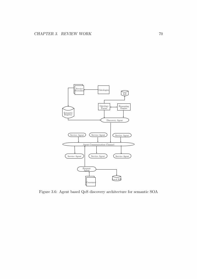
CHAPTER 3. REVIEW WORK 70
ServiceProviders
SemanticRegistry
Ontologies
Agent Communication Channel
Service Agent Service Agent Service Agent
Service Agent Service AgentService Agent
RequestAgent
Local KB
Discovery Agent
OntologyParser
ReasoningEngine
KB
Consumer
Figure 3.6: Agent based QoS discovery architecture for semantic SOA

CHAPTER 3. REVIEW WORK 71
leveraged agent-based architectures for semantic interoperability and func-
tional matchmaking, not much work has been done with respect to QoS in
semantic web services for Multi-Agent Systems (MAS). Most of these works
are based on dynamic QoS-aware discovery. In real-time enterprise environ-
ment, services are added and removed from the network on the fly. With
services defined as a composition of other services, invocation of the required
services may be chained or composite dependent on QoS of each service. In
view of this, there is a need for adaptive discovery approach that can ac-
commodate these run-time changes, the unpredictability introduced in the
system due to dynamic conditions and keep the system functioning despite
any run-time changes. In sync with the needs of Adaptive SOA the next
section explores works in the domain of adaptive QoS-aware discovery.
3.6 State of the Art
This section discusses the works in adaptive QoS-aware web service discov-
ery to understand the current state [97] and its gaps with respect to the
enterprise deployment. QoS-aware discovery requires choosing the best web
service from the host of multiple functionally similar services based on the
QoS constraints. It can be modeled as an optimization problem. An op-
timization problem is the one that has more than one feasible solution. It
uses an objective function to choose a unique solution under the given set of
constraints. It can be mathematically represented as follows:
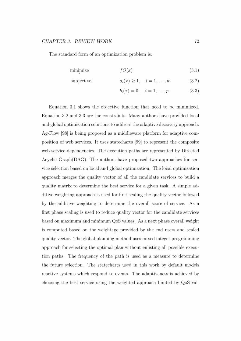
CHAPTER 3. REVIEW WORK 72
The standard form of an optimization problem is:
minimizex
fO(x) (3.1)
subject to ai(x) ≥ 1, i = 1, . . . ,m (3.2)
bi(x) = 0, i = 1, . . . , p (3.3)
Equation 3.1 shows the objective function that need to be minimized.
Equation 3.2 and 3.3 are the constraints. Many authors have provided local
and global optimization solutions to address the adaptive discovery approach.
Ag-Flow [98] is being proposed as a middleware platform for adaptive com-
position of web services. It uses statecharts [99] to represent the composite
web service dependencies. The execution paths are represented by Directed
Acyclic Graph(DAG). The authors have proposed two approaches for ser-
vice selection based on local and global optimization. The local optimization
approach merges the quality vector of all the candidate services to build a
quality matrix to determine the best service for a given task. A simple ad-
ditive weighting approach is used for first scaling the quality vector followed
by the additive weighting to determine the overall score of service. As a
first phase scaling is used to reduce quality vector for the candidate services
based on maximum and minimum QoS values. As a next phase overall weight
is computed based on the weightage provided by the end users and scaled
quality vector. The global planning method uses mixed integer programming
approach for selecting the optimal plan without enlisting all possible execu-
tion paths. The frequency of the path is used as a measure to determine
the future selection. The statecharts used in this work by default models
reactive systems which respond to events. The adaptiveness is achieved by
choosing the best service using the weighted approach limited by QoS val-
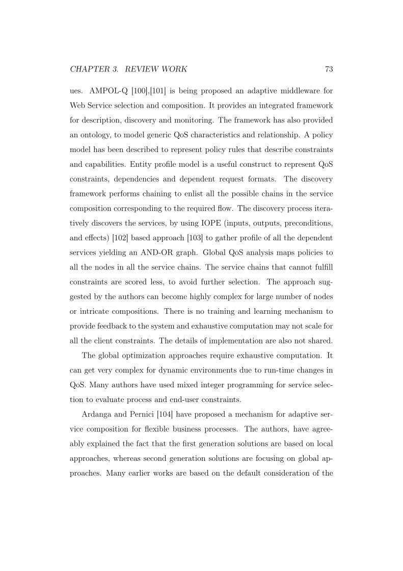
CHAPTER 3. REVIEW WORK 73
ues. AMPOL-Q [100],[101] is being proposed an adaptive middleware for
Web Service selection and composition. It provides an integrated framework
for description, discovery and monitoring. The framework has also provided
an ontology, to model generic QoS characteristics and relationship. A policy
model has been described to represent policy rules that describe constraints
and capabilities. Entity profile model is a useful construct to represent QoS
constraints, dependencies and dependent request formats. The discovery
framework performs chaining to enlist all the possible chains in the service
composition corresponding to the required flow. The discovery process itera-
tively discovers the services, by using IOPE (inputs, outputs, preconditions,
and effects) [102] based approach [103] to gather profile of all the dependent
services yielding an AND-OR graph. Global QoS analysis maps policies to
all the nodes in all the service chains. The service chains that cannot fulfill
constraints are scored less, to avoid further selection. The approach sug-
gested by the authors can become highly complex for large number of nodes
or intricate compositions. There is no training and learning mechanism to
provide feedback to the system and exhaustive computation may not scale for
all the client constraints. The details of implementation are also not shared.
The global optimization approaches require exhaustive computation. It
can get very complex for dynamic environments due to run-time changes in
QoS. Many authors have used mixed integer programming for service selec-
tion to evaluate process and end-user constraints.
Ardanga and Pernici [104] have proposed a mechanism for adaptive ser-
vice composition for flexible business processes. The authors, have agree-
ably explained the fact that the first generation solutions are based on local
approaches, whereas second generation solutions are focusing on global ap-
proaches. Many earlier works are based on the default consideration of the
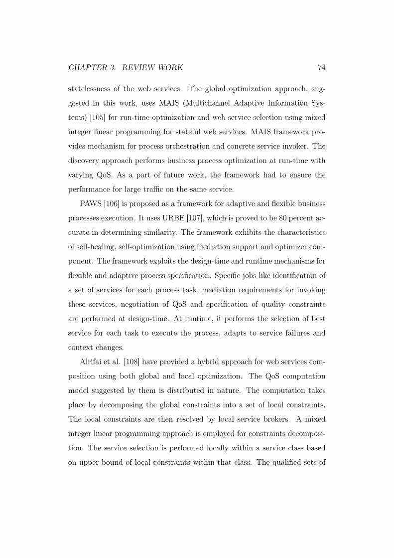
CHAPTER 3. REVIEW WORK 74
statelessness of the web services. The global optimization approach, sug-
gested in this work, uses MAIS (Multichannel Adaptive Information Sys-
tems) [105] for run-time optimization and web service selection using mixed
integer linear programming for stateful web services. MAIS framework pro-
vides mechanism for process orchestration and concrete service invoker. The
discovery approach performs business process optimization at run-time with
varying QoS. As a part of future work, the framework had to ensure the
performance for large traffic on the same service.
PAWS [106] is proposed as a framework for adaptive and flexible business
processes execution. It uses URBE [107], which is proved to be 80 percent ac-
curate in determining similarity. The framework exhibits the characteristics
of self-healing, self-optimization using mediation support and optimizer com-
ponent. The framework exploits the design-time and runtime mechanisms for
flexible and adaptive process specification. Specific jobs like identification of
a set of services for each process task, mediation requirements for invoking
these services, negotiation of QoS and specification of quality constraints
are performed at design-time. At runtime, it performs the selection of best
service for each task to execute the process, adapts to service failures and
context changes.
Alrifai et al. [108] have provided a hybrid approach for web services com-
position using both global and local optimization. The QoS computation
model suggested by them is distributed in nature. The computation takes
place by decomposing the global constraints into a set of local constraints.
The local constraints are then resolved by local service brokers. A mixed
integer linear programming approach is employed for constraints decomposi-
tion. The service selection is performed locally within a service class based
on upper bound of local constraints within that class. The qualified sets of
CHAPTER 3. REVIEW WORK 75
services are sorted based on utility function. This approach can scale and
provide near optimal solutions subjected to the fact that there is always pos-
sible to calculate lower and upper bounds on the local constraints for the
provided global constraints.
Adaptive SOA solution stack [109] gives insight, into the requirement of
handling adaptiveness at the operational, integration, and service component
layer level. This paper has taken a different approach, by ensuring the im-
portance to exhibit consistent adaptive behavior across all the layers beyond
application layer [110]. Enterprise Service Bus (ESB) [111] is the de-facto
standard for message-oriented middleware for SOA systems. The authors
have implemented adaptive ESB at the integration services layer for central-
ized monitoring and re-routing pipeline. They have left the discussion of
adaptation across multiple layers as an opportunity to be explored further.
The tool set of adaptation across all the layers was yet under development
when this study was conceived. The use of ESB or SOA middleware, require
centralization of all the monitoring and routing decisions. This is an effec-
tive solution. The limitation is ESB being a centralized component [112],
can become a single point of failure.
Beneviste et al. [113] has proposed a mathematically sound framework for
contract-based management of service orchestrations having data-dependent
workflows. The authors used probabilistic QoS [114] to handle uncertainties
in service composition flows. Most of the works assume data independence
for composition workflows. The aim of the work is to model service orches-
trations monotonically despite data-dependence. The capability to provide
monotonicity for these orchestrations QoS calculus has been developed for
compositions to deal with uncertainty in QoS computation. The authors have
developed Orchnet as a model for QoS-aware service composition defined as

CHAPTER 3. REVIEW WORK 76
a model to capture QoS in composite services. This model is an extension
of Petri net based modeling [115] of service orchestrations. Probabilistic
OrchNets are then developed based on Orchenet modeling to deal with prob-
abilistic QoS. The work done by authors does formalize the importance of
monotonicity in service orchestrations mathematically.
The Table 3.3 summarizes the works discussing adaptive service discovery
based on non-functional properties in SOA systems.
3.7 Summary
This chapter reviewed existing works providing insight into the methodolo-
gies and approaches supporting agile development and QoS-aware discovery
in SOA systems. Enterprise SOA deployments are facing a paradigm shift
with the next wave towards adaptive [116] processes and systems. The true
vision of Adaptive Service-Oriented Enterprise (ASOE) requires understand-
ing the needs of implementing Adaptive SOA. The discovery is an inherent
need for SOA systems being distributed in nature. Enabling reuse via shared
repository requires managed discovery of shared services. The proliferation
of services offering similar functionality is common due to rapid adoption and
vast deployment needs of SOA. Many of these services are similar in func-
tionality but they differ in QoS provided by them. In such a case, managing
redundancy at run-time shall help delivering value from all these services
without creating silos and inconsistency in an enterprise environment. In
fact this measured QoS-aware systems require managed redundancy as a first
step. Further steps would require QoS management followed by discovery
mechanism. Shared repository offers a static publishing model for managing
redundancy. External monitoring frameworks and dynamic approaches are

CHAPTER 3. REVIEW WORK 77
Pap
erQoS
Mod
elObjective
G/L
Algorithm
[100
]
Anextensionof
OW
L-Sas
aseman
-ticQoS
ontology
mod
el.QoS
Fea-
turesarerepresentedas
polic
yrules.
Ameta-specification
isused
toen
-forcean
devalua
tethesepo
licyrules
AMPOL-Q:A
nad
aptive
mid-
dlew
arefram
eworkfordiscov-
eryan
dcompo
sition
G
ServiceDiscovery
ispe
rformed
byfirst
using
IOPE,follo
wed
byde
-scription
ofall
possible
service
chains
intheprocesselim
inatingthe
ones.
[98]
Anextensible
QoS
mod
elis
defin
edformulti-dim
ension
alQoS
.It
has
been
representedform
ainlyfiv
eQoS
criteria.
Ag-Flow:A
middlew
areplat-
form
that
performsop
timiza-
tion
and
re-con
figuration
ofservicecompo
sition
.
L/G
The
glob
alop
timization
approa
chuses
MIP
tode
term
inetheservices
basedon
varyingconstraintsdu
ring
run-timeforthegivenop
timization
func
tion
.
[106
]A
genericQoS
mod
elis
specified
todefin
eQoS
characteristics.
PAW
S:A
fram
eworkforbu
si-
ness
processop
timizationan
dad
aptation
forchan
ging
con-
texts
GMIP
isused
for
optimization
ex-
ploiting
both
design
-tim
ean
drun-
timemod
ules
forad
aptation
.
[104
]Anextensible
QoS
mod
elis
defin
edba
sed
onthe
aggregation
pattern
andnego
tiab
ility
Ada
ptiveservicecompo
sition
andop
timization
GMIP
isused
forserviceselectionus-
ingMAIS
architecture.
[108
]A
genericQoS
mod
elha
sbe
enas-
sumed
withdiscrete
QoS
values
Dyn
amic
servicecompo
sition
basedon
client
constraints
H
MIP
isused
todivide
glob
alcon-
straints
into
distribu
ted
localcon-
straints
follo
wed
byadistribu
tedlo-
cals
ervice
selection.
[113
]A
prob
abilistic
mod
elfor
multi-
dimension
alQoS
isused
toha
ndle
mon
oton
icity
QoS
-aware
man
agem
ent
ofmod
eling
mon
oton
icservice
orchestrations
forda
tade
pen-
dent
workfl
ows
L/G
Amathe
matically
soun
dfram
ework
forcontract
based
QoS
-aware
ser-
vice
compo
sition
sha
sbe
ende
vel-
oped
.
Table3.3:
Literature
Survey
forAda
ptiveQoS
-awareap
proa
ches
forSO
Asystem
s.
LLoc
alop
tim
izat
ion
GG
loba
lO
ptim
izat
ion
HH
ybri
dM
IPM
ixed
inte
ger
prog
ram
min
gM
AIS
Mul
tich
anne
lA
dapt
ive
Info
rmat
ion
Syst
ems
CHAPTER 3. REVIEW WORK 78
used to enable dynamic discovery. Adaptation requires self-managed frame-
works. State of the Art work in Adaptive QoS-aware discovery reveals that
this problem is modeled as an optimization problem in the literature. How-
ever there is a need of managed redundancy, that is yet not been addressed,
which shall make re-use easy and natural. The review work results in two
key observations. Firstly, it is required to formally address Agile SOA de-
velopment for non-functional requirements enabling Adaptive SOA design.
Secondly, there is a need to enhance the dynamic discovery approaches to
address adaptive enterprise needs. Considering these needs the next chapter
explains the first key contribution of this work, which is a formal methodology
to design Agile SOA systems.Later chapters address the second observation
and need resulting in the design and development of Adaptive QoS-aware
discovery framework.

Chapter 4
Agile SOA Methodology
4.1 Introduction
In current dynamic scenarios business develops faster than organizational
structure, which is most often true for IT-driven organizations. Business
groups form and purge with changing business demands. Increased need of
globalization led by re-occurring economic crisis has put lot of demands on
agility and flexibility. Organizations have addressed this inadvertent need
of organizational agility by adopting cultural, technological and process-
oriented changes as required. SOA addresses the issue of organizational
agility [117] by adapting applications to suit business requirements. Agile
development methodology has also been widely adopted and supported by
evangelist to yield agility. Agility is achieved through regular cadences of
work, known as Sprints or iterations, at the end of which teams must present
a potentially shippable product increment. By focusing on the repetition of
abbreviated work cycles as well as the functional product they yield, agile
methodology is described as ‘iterative’ and ‘incremental’. Agile and SOA
complement each other with common goals of agility and flexibility. Using
79

CHAPTER 4. AGILE SOA METHODOLOGY 80
them together can yield designing robust large-scale SOA systems in lesser
time and shorter delivery cycles. This will lead to cost-effective solution with
greater customer satisfaction.
Applying agility to SOA will require it to scale agile. A successful archi-
tecture needs to consider both functional and non-functional characteristics.
There may be multiple ways to provide same functionality. However non-
functional requirement is discerning criteria to choose the required function-
ality. It is very important not to compromise on quality even though product
life cycle time is reduced. One way to ensure this is by involving customers
who could give their constant feedback on working systems and products to
them. However there is a need to ‘design SOA systems in quality’. This
means relevant aspects of quality need to be handled while determining the
design of SOA systems from all the key stakeholders including customers.
Quality Function Deployment was originally introduced [118] for product de-
velopment in 1980s. It is explained, as an approach to encourage ‘Design
in Quality’, by translating customer needs into design objectives. Classical
QFD approach was mainly used in industrial and manufacturing domain.
Though it could be used for software but due to basic differences between
development approaches of software and hardware [119], it was more success-
ful with manufacturing industry. Richard Zultner formally integrated QFD
with software engineering for the first time in 1987 by introducing Blitz QFD
approach. It provides systematic, matrix-free [120], low-cost , lean [121] and
extensible approach for software development.
This chapter explains the Blitz-Collaborative SOA (Blitz-CSOA) tech-
nique as an extension of Blitz Quality Function Deployment Blitz QFD
methodology [16] to design SOA systems. The modified methodology yields
prioritized functional and non-functional requirements derived from customer

CHAPTER 4. AGILE SOA METHODOLOGY 81
feedback. It is an extension of Blitz-QFD, which is one of the most promi-
nent Software QFD [16] technique. The next section explains the modified
Blitz QFD to set the context of Blitz-CSOA.
4.2 Blitz-QFD
Richard Zultner, co-founder of the QFD institute first introduced Blitz QFD
[119] in 1990s for ever-changing software landscape in terms of technology
and business models. In contrast to traditional QFD that is based on heavy
matrix based approach Blitz QFD is matrix-free. Its lean nature makes it
promising for adoption in Software world. Figure 4.1 demonstrates nine steps
of Blitz QFD. In this section all the steps of Blitz QFD are discussed in brief.
Step 1: Project Goals
This step determines the key project goals that define the success of the
project. The project goals are defined based on organizational strategy,
which is multi-dimensional. The strategy is based on various impacting
factors like market models, behavioral patterns of organizational busi-
ness, strengths on which business is done. Tighter alignment of project
goals to organizational strategy ensures allocating resources correctly,
eliminating redundancies in job area, tasks and executing what is really
useful to the organization. In fact goals cannot be defined successfully
unless they are aligned to strategy. In order to determine the true
success these goals need to be specific, measurable, achievable, time-
bound and most importantly relevant to organizational strategy. Based
on these the output of this step is a Project Goal Table that enlists the
goals and corresponding ways to measure them (How measured: Target
state, Current State, New State), Time frame, Means of achieving the

CHAPTER 4. AGILE SOA METHODOLOGY 82
same. Once the goals are defined the next step is to determine the key
customer segments related to these goals.
Step 2: Customer Segmentation
This step identifies the key customers i.e. those who will impact the
goals positively. There can be a large number of customers impacting
the projects. However it is important to identify them based on the rel-
ative merit. This merit is determined by the impact of these customers
on the project goals. The table relates each goal to type of customer.
For example for a procurement project the customer segments will be
employee, operations staff, approval manager, accounts team , accounts
manager.
For a CRM system it can Sales and Marketing manager, Support staff,
Clients and Security Manager. All of these customers will have variable
impact on each project goal. Customer segment table enlists all the
goals and studies their behavior with respect to who (customers) will
get impacted or are responsible for execution of these project goals,
why do they use them responsible and why is the system.
Based on these inputs the relative prioritization of these customers
is calculated for these project goals. There can be large number of
customers related to the project but this step ensures that we take only
critical ones. Once these customers are identified the relative impact of
these customers is determined based on the delivery of the project goals.
This shall yield the key customers eliminating the ones that are not
required. Once the customers are characterized along with their relative
merit the next step is to understand the key phases of the system. This

CHAPTER 4. AGILE SOA METHODOLOGY 83
is determined using process modeling. The next step determines the
current process model based on the customer interaction.
Step 3: Process Steps
This step analyzes the AS-IS state of customer context using process
models in the form of Data flow diagram. It indicates the sequence of
steps and phases to understand how key customer segments interact
with the system. There can be various business process model views
from the perspective of key customers. The project teams designs this
process map based on their understanding as well as the customer in-
puts to determine how they will interact with the system. The basis
of interviewing customers in their real work environment is to under-
stand where do they need improvements in a process model. This step
helps driving the next step, which captures customer verbatims to un-
derstand their needs and pain points to capture the benefits needed
by them. The next step is based on the famous Japnese term called
Gemba
Step 4: Gemba Visit
Gemba is a Japnese word meaning ‘in real place’. It is explained nicely
in the book [122].
"Gemba. What a wonderful word. The place—any place in any organization—
where humans create value. But how do we understand the gemba?
And, more important, how do we make it a better place—one where
we can create more value with less waste, variation, and overburden
(also known, respectively, as muda, mura, and muri)?"
CHAPTER 4. AGILE SOA METHODOLOGY 84
This step is very important for Software QFD as most of the software is
developed to be used by others. Being at the customer site helps cap-
turing customers verbatims and elimination of any assumptions being
made by development team on behalf of customers.
A typical Gemba table captures customer observations, verbatims and
team notes for each process step in the process model. These verbatims
help capturing customer needs in the next step.
Step 5: Customer Needs
The clarified statements provided by the customers in the previous
step need to be mapped to benefit-statements. These statements are
solution-independent customer desires. In order to enlist these needs
Customer Voice Table is built in this step to map the inputs received
in previous steps to be mapped to the needs .
These needs can be large in size. It is important to analyze them in view
of the various dimensions in the development scope to see which one
to use. Some of these inputs will come while mapping these needs to
the functional and non-functional requirements. The Affinity diagram
helps in classifying these needs based on similarity. The next step
analyzes these needs further into Hierarchy diagram
Step 6: Analysis of Customer Needs
In this step customer needs are structured and grouped in a way to
uncover high-value needs. It organizes these needs with respect to each
other so as to evaluate them to uncover any unstated needs of cus-
tomers. It is basically a requirements discovery mechanism to analyze
and derive needs that is not spoken bur desired by customers. Post this,

CHAPTER 4. AGILE SOA METHODOLOGY 85
the needs are prioritized using Analytical Hierarchy Process (AHP) as
explained in the next step.
Step 7: Prioritize the Customer Needs
The relative prioritization of these structured needs is done using An-
alytical Hierarchy Process. This shall help determining the priority
of top-down needs to identify the top priority (10 to 20) needs that
captures less than 30 to 40 percent of the key requirements. The inten-
tion is to discover only sufficient requirements that need to be deployed.
The remaining needs can go through iterations in the next phase. Once
these top needs are determined, now is the time to deploy these needs
by mapping them to design requirements. The next step explains the
same.
Step 9: Deploy Customer Needs
This step determines solution characteristics and tasks corresponding
to the high-value needs. The tool used in this case is called Maximum
Value Table (MVT). It provides a way to deliver most important cus-
tomer needs. It is at this stage when design requirements are listed
corresponding to these needs along with the tasks needed to achieve
them. The project has now entered into requirement elicitation corre-
sponding to these needs.
The next section explains Blitz-CSOA, which begins by extending Blitz QFD
at this step.

CHAPTER 4. AGILE SOA METHODOLOGY 86
4.3 Blitz-CSOA
In software real value comes in designing the system based on customer de-
mands [123]. Collaborative SOA design including key customers and stake-
holders is realised as an important factor for the success of product or system
delivered. There is a lot of research done to affirm the importance and ne-
cessity of customer participation in collaborative design methodology. Mills
and Morris [124] explained the involvement of customers leading to consis-
tent productivity improvement for organizations. The continued customer
loyalty [125] is another need to ensure run-the-business needs. The study
[126] has suggested involving customers beyond requirement gathering in a
way to provide product value. Such a technique will be more beneficial for
complex design of distributed systems. SOA is the key architecture to realise
distributed systems [127] for enterprises.
All the steps of original Blitz QFD are shown in detail by [16] in his book .
We have modified this technique into Blitz-CSOA as shown in Figure 4.1. All
the steps are same till step 9 as Blitz QFD. Step 10 onwards we have modified
this approach for robust and collaborative SOA design. The highlighted
portion of Figure 4.1 is new and modified steps in this approach. The first
step involves incorporating contextual information in the SOA design.
The next section discusses the first step added as a modification to the
Blitz-QFD flow.
4.3.1 Context Information
Contextual information serves as a very important factor for non-functional
requirements. Without relevant contextual information would amount to
considering the very big picture that shall not amount to much of benefit.

CHAPTER 4. AGILE SOA METHODOLOGY 87
Figure 4.1: Blitz CSOA
CHAPTER 4. AGILE SOA METHODOLOGY 88
For example ‘Usability’ may be one the key design requirements. Without
specifying the contextual information [128] the simple information for ‘Prod-
uct Catalogue to be useful’ may not be meaningful. The information like
which components are needed to be usable shall be helpful to narrow down
the problem domain. This step mandates providing contextual information
for design requirements and most importantly for non-functional require-
ments [129] determined in Step 9. This results in SOA context table in Step
10. The clarity of context will be carried forward to next step to yield agile
development [130]. Wherever possible this information should be provided
for functional design requirements as well. Considering the fact that mapping
customer needs into design requirements usually loses the contextual infor-
mation [39] this marks as one of the key steps. The next section explains the
step added to incorporate relative prioritization using HOQ Matrix.
4.3.2 HOQ Matrix
House of Quality (HOQ) matrix is an important tool in QFD, which captures
number of key impacting factors in the planning phase. It translates the cus-
tomer needs into a prioritized targets based on different impacting factors.
This work adds Step 11 to derive HOQ for design requirements. This step
11 derives its motivation from the work done in [131], that determines addi-
tionally the House of Quality (HOQ) matrix for non-functional requirements
apart from functional requirements. This matrix results in determining the
relative priority of the design requirements based on the customer needs. The
row and columns for the HOQ matrix are as follows:
1. Each row describes voice of the customer modeled as customer need or
demand
CHAPTER 4. AGILE SOA METHODOLOGY 89
2. Each column describes a measure to respond to these needs. In this work
it represents design requirement. A single requirement can affect the
varying customer needs in different manner.
3. Each cell asks the domain experts ( architects/design team) to evaluate
a relationship between the intersecting row and column.
In order to evaluate the relationship this work has devised two possible
weightage for Saaty scale [132] using normal and convex distribution for the
calculation of HOQ matrix to cater to a gradual or expedited software deliv-
ery. In order to calculate HOQ matrix the needs are assigned weights (W)
based on the global priority determined as a part of Analytical Hierarchy
Process (AHP) [133] analysis shown in Step 8. Equation (4.1) - (4.4) shows
the calculation of HOQ matrix. The customer needs and requirement are
represented by j and k respectively. Sj,k denotes the Saaty score assigned
to each combination of customer needs and requirements in Equation (4.1).
Equation (4.2) is a function of Equation (4.1), which assigns priority rating
to Saaty values. In this study we have used normal and convex distributions
to define these functions. Given that each customer need is associated with
a weight (Wj), the absolute weight (AWk) associated with each requirement
is then calculated as a weighted sum of priorities in Equation (4.3). The
Requirement Weights (RWk) is finally obtained by normalization of the ab-
solute weights with its sum. The function f(Sj,k ) to assign priority weight
is mathematically defined as follows:
Sj,k ∈ [1− 9] (4.1)
Pj,k = f(Sj,k) (4.2)
CHAPTER 4. AGILE SOA METHODOLOGY 90
AWk =∑j
WjPj,k (4.3)
RWk =AWk∑k AWk
(4.4)
The design requirements are compared with respect to their impact on
customer needs and rated based on strength of relationship assigned using
Saaty scale. Saaty Scale weightage HOQ matrix is determined based on 9-
point Saaty scale with a range of 1 as weak and 9 as extreme relationship.
Equation 4.5 - 4.8 shows the normalized distribution employed for calculating
weightages for Saaty scale. φ(x) is normal distribution. fn(x) is a function
of φ(x) with mean of 10 and standard deviation 5.
φ(x) =1√2πe−
12x2
(4.5)
fn(x) =1
5φ(x− 10
5) (4.6)
M =Max(fn(i)), i ∈ [1− 10] (4.7)
Pj,k = fn(Sj,k )/M, Sj,k ∈ [1− 9] (4.8)
Equation 4.8 determines the weightage for priority. Figure 4.2 shows
the graph for normalize Gaussian curve. The highlighted portion is used for
calculating Saaty scale priority weights. Similarly Equation (4.9) to Equation
(4.11) shows the convex function employed in calculation of Saaty weights.
f(x) is a convex function.
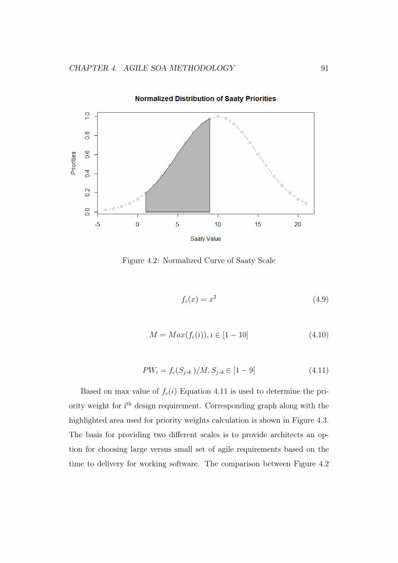
CHAPTER 4. AGILE SOA METHODOLOGY 91
Figure 4.2: Normalized Curve of Saaty Scale
fc(x) = x2 (4.9)
M =Max(fc(i)), i ∈ [1− 10] (4.10)
PWi = fc(Sj,k )/M, Sj,k ∈ [1− 9] (4.11)
Based on max value of fc(i) Equation 4.11 is used to determine the pri-
ority weight for ith design requirement. Corresponding graph along with the
highlighted area used for priority weights calculation is shown in Figure 4.3.
The basis for providing two different scales is to provide architects an op-
tion for choosing large versus small set of agile requirements based on the
time to delivery for working software. The comparison between Figure 4.2
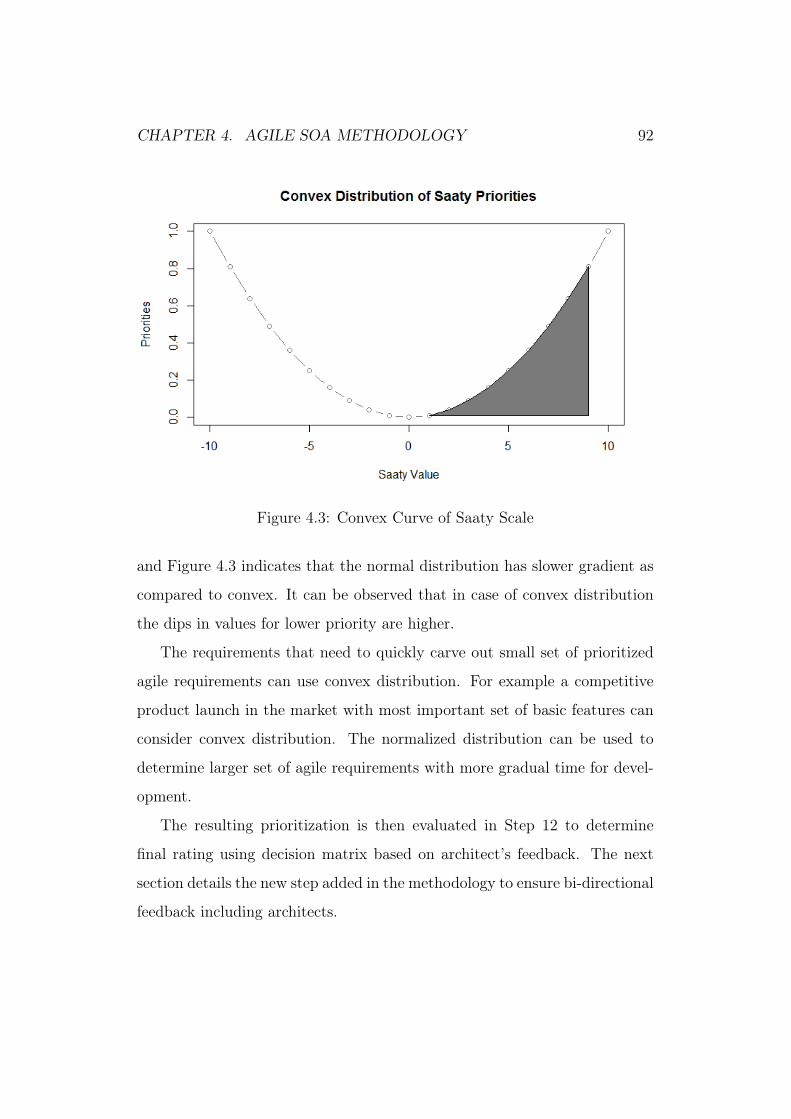
CHAPTER 4. AGILE SOA METHODOLOGY 92
Figure 4.3: Convex Curve of Saaty Scale
and Figure 4.3 indicates that the normal distribution has slower gradient as
compared to convex. It can be observed that in case of convex distribution
the dips in values for lower priority are higher.
The requirements that need to quickly carve out small set of prioritized
agile requirements can use convex distribution. For example a competitive
product launch in the market with most important set of basic features can
consider convex distribution. The normalized distribution can be used to
determine larger set of agile requirements with more gradual time for devel-
opment.
The resulting prioritization is then evaluated in Step 12 to determine
final rating using decision matrix based on architect’s feedback. The next
section details the new step added in the methodology to ensure bi-directional
feedback including architects.

CHAPTER 4. AGILE SOA METHODOLOGY 93
4.3.3 Determination of agile requirements by architects
Architects and developers may not be first hand users of the system. There-
fore they need to collaborate with the customers to understand their needs.
Heiskanen [134] has emphasised in his work the need for development team
to work collaboratively with the customers to yield a stable design. Agile
development methodology does ensure customer participation in its mani-
festo. However it is not just important to get high-value design requirements
derived from customer demands but also to understand their complexity.
This would successfully develop an agile system with required set of agile
attributes [135] for multiple iterations.
Considering the same Step 12 creates agile set of requirements based on
architect’s feedback. Though HOQ matrix developed in Step 11 yields the
relative priority of design requirements, it is not reflecting design architect
views. This step ensures each of these requirements is weighed by archi-
tects in Step 12.The requirements, which are non-core to the system can be
weighted lower and considered at later stage. While requirements, which are
core to system, should be weighted higher. These weights in collaboration
with the relative values obtained from previous step for both normal and
convex Saaty weights are used to derive agile set of requirements.
Let Wk ∈ [1 − 10] be the priority assigned by architect to kth design
requirement for mth criteria. In this case m is either convex or normalize.
In order to calculate the agile weights a decision matrix is formed for k
alternatives and m criteria. The resulting agile weight (RA) is calculated as
follows
Wk ∈ [1− 10] (4.12)
CHAPTER 4. AGILE SOA METHODOLOGY 94
m =
1 for normal
2 for convex
(4.13)
RAk,m =Wk ∗RWk,m∑kWk ∗RWk,m
(4.14)
This enhancement to the system provides an early architectural feedback
in the design process. The collaborative nature of this process is a marked
differential, which intends to make it more aligned to agile software develop-
ment technique and hence increase the overall adoption of QFD methodology
as a whole. The next section explains the rationale of these stages.
4.4 Why these stages?
The existing Software QFD methodology is very generic. In order to use it
in context of real-time enterprise SOA deployment the following need to be
addressed:
1.) While focusing on customer value it lacks ability to capture bi-directional
feedback from design stakeholders (eg: Architects) in the system.
2.) It does talk of deriving design characteristics based on high value cus-
tomer needs but does not mandate the inclusion of NFPs.
Blitz QFD ensures derivation of design characteristics from customer
stated and unstated needs. Non-functional Properties(NFPs) evolve most
naturally from unstated needs. Till Step 8 in Blitz-QFD the customer needs
are stated, explored and analyzed to yield high value needs with due consid-
eration of all the dimensions of project. At Step 9 these high-value needs are
CHAPTER 4. AGILE SOA METHODOLOGY 95
mapped to solution characteristics (features) and non-functional characteris-
tics. It is very well realized that contextual information plays an important
role in actual and complete determination of design characteristics. Once
these characteristics are determined it is important to review them to add
enough contextual information. Context describes the interactions between
humans, applications, and the environment in which a given application will
be used. The context has a real impact on the design and specifically on
non-functional characteristics. Missing functionality would amount to miss-
ing a feature but missing contextual information can have a lasting impact
on customer satisfaction and adoption. To exemplify:
A design requirement can be to develop a common interface to avoid
multiple entries into the system. This is a potential use case of SOA exposing
single interface for multiple clients.
However it would be worthwhile to add the context information in which
this application will be used. For example whether it will be used by mobile
devices or web-based client, on a dedicated physical-storage or cloud based
storage, bandwidth constraints, within firewalls or externally etc.
Considering the last use case for external facing applications. Security is
a paramount requirement. There may be a need to design interfaces, which
do not expose critical data by default or provides specialized APIs just for
secure data. For mobile clients for example a restricted capability of no
search capability while search can be enabled for on-the-premise usage. In
nutshell it is very important to add context information for the non-functional
characteristics to design the product based on user experience.
This step can be interleaved with the development of Maximum Value
table (MVT) based on the maturity of QFD in the project.
Once the design characteristics are refined with contextual information

CHAPTER 4. AGILE SOA METHODOLOGY 96
the next step is to determine prioritized design requirements using HOQ.
HOQ can be a natural transition step, post MVT. This step is improvised to
cater to two major requirements
• First HOQ for non-functional characteristics for SOA systems is intro-
duced
• Secondly two new scales have been developed to fulfill the varied needs
of prioritization of design requirements
The two new scales provide the flexibility to develop and launch product
based on impacting arrributes such as time constraints, competitiveness and
delivery capabilities of the team. This step will only be created after Step9
once the design characteristics are obtained. The result of this step is a
prioritized set of design requirements.
Once these requirements are obtained the next step ensures the need to
conclude the priorities of agile requirements based on not only customer ver-
batim but design team (Architect) feedback who has end-to-end understand-
ing of the real-time development, deployment constraints, company policies
and competitive market constraints for the product launch. The next sec-
tion applies the methodology step by step on a case study for Business-to-
Business( B2B) purchasing system.
4.5 Case Study
The aim of this case study is to redesign a B2B e-procurement system for a
large global enterprise using Blitz-CSOA methodology. The existing procure-
ment system is not based on service-orientation. The components interact
with each other using application specific logic that is extended on-demand
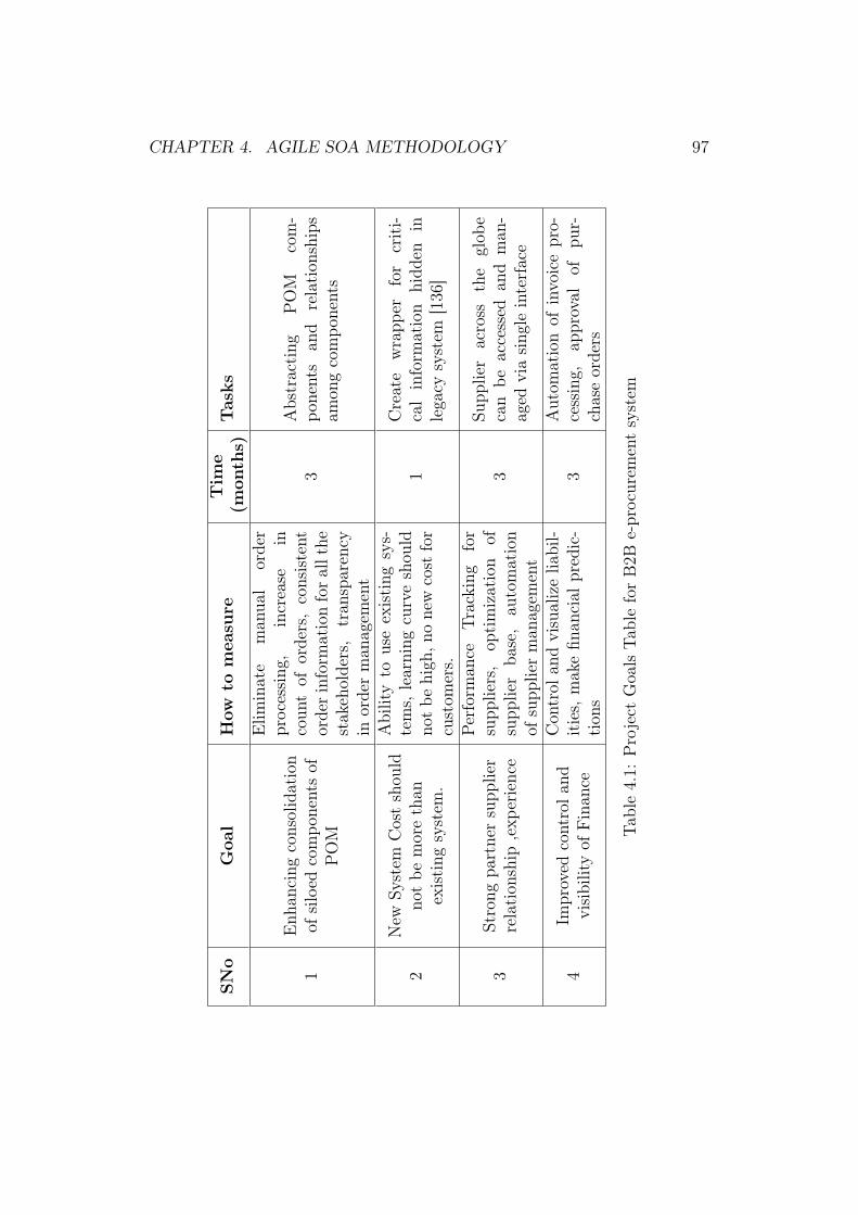
CHAPTER 4. AGILE SOA METHODOLOGY 97
SNo
Goal
How
tomeasure
Tim
e(m
onths)
Tasks
1Enh
ancing
consolidation
ofsiloed
compo
nentsof
POM
Elim
inate
man
ual
order
processing
,increase
incoun
tof
orders,consistent
orderinform
ationforallthe
stak
eholders,
tran
sparency
inorderman
agem
ent
3Abstracting
POM
com-
ponents
and
relation
ships
amon
gcompo
nents
2New
System
Costshou
ldno
tbe
morethan
existing
system
.
Abilityto
useexisting
sys-
tems,
learning
curveshou
ldno
tbe
high
,nonew
cost
for
custom
ers.
1Create
wrapp
erfor
criti-
calinform
ation
hidd
enin
lega
cysystem
[136
]
3Strong
partnersupp
lier
relation
ship
,exp
erience
Perform
ance
Tracking
for
supp
liers,
optimization
ofsupp
lier
base,
automation
ofsupp
lierman
agem
ent
3Su
pplier
across
the
glob
ecan
beaccessed
and
man
-ag
edviasing
leinterface
4Im
proved
controla
ndvisibilityof
Finan
ce
Con
trol
andvisualizelia
bil-
ities,
mak
efin
ancial
predic-
tion
s3
Autom
ationof
invoicepro-
cessing,
approval
ofpu
r-chaseorders
Table4.1:
Project
Goa
lsTa
bleforB2B
e-procurem
entsystem
CHAPTER 4. AGILE SOA METHODOLOGY 98
based on growing business needs. It is non-extensible platform specific logic
that becomes complex and unmanageable [137] for any dynamic customer re-
quirement. Loosely coupled extensible architecture [138] is the need for this
existing system that is best achieved by using SOA. The key steps of Blitz-
CSOA are demonstrated along with results and derivations of agile functional
and non-functional requirements.
The first step defines project goals for e-procurement system. The goals
ensure clear definition of the business objectives that need to be achieved.
The output of this step is a Project Goals Table, which defines goals, how to
measure them, expected time required, and tasks required to achieve them.
Table 4.1 lists the project goals for e-procurement system. Redesigning
the system from scratch is costly. In order to build an interoperable sys-
tem leveraging most of the existing business logic SOA is used to enable
integration.
Step 2 identifies the key customers interacting and impacted by the sys-
tem. These customers also determine the future state of the system. Provid-
ing customer segmentation to identify key customers along with their type
of impact results in Customer Segment Table. Procurement Team, Sales, In-
ventory and Accounts are the key customers directly interacting or impacted
by the design of e-procurement system. In case of this system these cus-
tomers are also the key stakeholders since they bear the risk of overrun and
design of system. Hence though it is technically possible to use SOA but it
is inadvertently important to interact with responsible customer segments.
Table 4.2 describes the customer segments along with the roles, time they
take to interact with the system, issues aced and their views on the future
state. For example one of the major issues for purchasing teams is multiple
ordering systems for different business units. Team views it to resolve by

CHAPTER 4. AGILE SOA METHODOLOGY 99
Custom
erSegment
Who
What
When
(%)
Where
Why
How
Purchasing
Procurement
man
ager
andTe
am.
For
raising,
man
aging
PO
50Multiple
Ordering
Portals
man
uala
ndno
n-au
tomated
interactionwith
compo
nents
prov
iding
consolida-
tion
for
integration
end-po
ints
Sales
SalesLe
adan
dsales
team
Forsales
prediction
15
Needto
interact
with
Inventory
and
Purchasing
system
s
man
ualinteraction
withpu
rcha
sing
team
toan
alyzean
dpredict
salesop
portun
ities
design
sing
letouch-
pointto
inventorysys-
tem
which
lead
sto
furtherdetails.
Inventory
Inventory
and
Goo
ds-in
team
Forstock
analysis
and
prediction
20
Inventory
and
Purchasing
System
logicforinventory
data
view
isrespon
sibilityof
clients
develops
consistent
in-
terfaces
forinv
entories
tobe
used
glob
ally
Accou
nts
Accou
nts
team
Forecast
for
accoun
ts10
Accou
nts
System
Multipletouch-po
ints
toaccoun
tsinform
ationan
ddevelopconsolidated
abstractionlayerwith
shared
interface.
Table4.2:
Customer
Segm
entTa
bleforB2B
e-procurem
entSy
stem

CHAPTER 4. AGILE SOA METHODOLOGY 100
Figure 4.4: Extract of Gemba Visit Table for E-procurement System
providing single interface for an ordering system for all business functions. It
is possible with SOA by providing a common interface to existing ordering
applications in short-term and incorporating common business logic for all
ordering application via single interface in long-term. Consolidation will also
yield in cost reduction, control and visibility, as is also the goal of project.
Step 3 is customer process model creation to understand the whole flow of
current process. The key processes in e-procurement system are PO creation,
PO approval, Sending PO and receiving goods. The customer process model
also captures customer concerns in process steps.
Step4 is termed as Gemba visit which means interacting with customer on
their site [131] to understand their end-to-end interaction with the system. It
captures nature of interaction, interviewer, and interviewee verbatim, issues
and time of interaction using Gemba Visit Table [139]. Figure 4.4 shows the
extract of Gemba visit table resulted on interviewing a senior procurement
employee while interacting with the system. For example after going through
the interaction it is understood that existence of multiple systems is leading
to inconsistent and redundant data in the system.
Step 5 captures voice of customer and translates them into needs using
Customer Voice Table. Customer voice may point to concerns, issues or
requirements, which needs to be addressed. This may not be the true need,
since they may not have end-to-end understanding of the domain and may

CHAPTER 4. AGILE SOA METHODOLOGY 101
Figure4.5:
Hierarchy
Diagram

CHAPTER 4. AGILE SOA METHODOLOGY 102
be limited to a particular customer segment. These needs are further carried
and acted upon in future steps.
Step 6 performs categorisation of these needs by arranging them into
affinity groups. During this process any unstated and implied needs is also
included in the group. Affinity Diagrams are used to represent the resulting
structured needs.
Step7 arranges the resulting structured needs into primary, secondary and
tertiary levels using Hierarchy diagram. The diagram shows the needs along
with secondary and primary categorisation.
Step 8 applies Analytical Hierarchy Process on these needs to assign global
and local priority. Figure 4.5 shows the Hierarchy Diagram of this system
with global and local priority. In this case primary categorisation is customer
segment interactions. Second level is type of interaction and third level is the
actual needs in those interactions. For example online acknowledgement for
Purchase Order (PO) by vendor is a vendor management function related to
input or output of PO by procurement team. The global priority of the needs
is taken forward in next step to determine Maximum Value Table (MVT).
Step 9 is a key milestone since in this step customer needs are trans-
lated into design requirements. In Blitz-CSOA, it is required to map needs
into non-functional requirements. Injection of non-functional requirements
reassures the customer satisfaction with highly usable and robust design.
The output of this step is a set of design requirements to be considered for
deployment
At this point, the requirements are filtered based on priority to determine
high-value design requirements.
Step 10 is a new step in Blitz-CSOA to add SOA contextual information
to resulting design requirements.
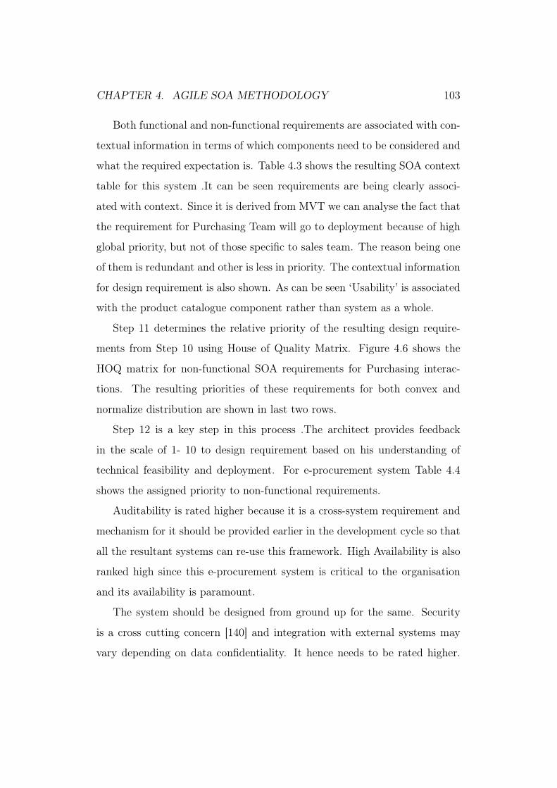
CHAPTER 4. AGILE SOA METHODOLOGY 103
Both functional and non-functional requirements are associated with con-
textual information in terms of which components need to be considered and
what the required expectation is. Table 4.3 shows the resulting SOA context
table for this system .It can be seen requirements are being clearly associ-
ated with context. Since it is derived from MVT we can analyse the fact that
the requirement for Purchasing Team will go to deployment because of high
global priority, but not of those specific to sales team. The reason being one
of them is redundant and other is less in priority. The contextual information
for design requirement is also shown. As can be seen ‘Usability’ is associated
with the product catalogue component rather than system as a whole.
Step 11 determines the relative priority of the resulting design require-
ments from Step 10 using House of Quality Matrix. Figure 4.6 shows the
HOQ matrix for non-functional SOA requirements for Purchasing interac-
tions. The resulting priorities of these requirements for both convex and
normalize distribution are shown in last two rows.
Step 12 is a key step in this process .The architect provides feedback
in the scale of 1- 10 to design requirement based on his understanding of
technical feasibility and deployment. For e-procurement system Table 4.4
shows the assigned priority to non-functional requirements.
Auditability is rated higher because it is a cross-system requirement and
mechanism for it should be provided earlier in the development cycle so that
all the resultant systems can re-use this framework. High Availability is also
ranked high since this e-procurement system is critical to the organisation
and its availability is paramount.
The system should be designed from ground up for the same. Security
is a cross cutting concern [140] and integration with external systems may
vary depending on data confidentiality. It hence needs to be rated higher.
CHAPTER 4. AGILE SOA METHODOLOGY 104
Segments
Needs
Wt
Cap
abilities
Functional
Req
Non
-Functional
Req
Tasks
Purchasing
Team
Customersneed
sing
leinterfaceforallprod
-uct
8.9
Produ
ctda
taread
ilyavail-
able
forPOM
FR1:
Enterprise
wide
master
data
forprod
uct
QU1:
Usability
ofProdu
ctCatalog
QU2:Interope
rability
with
Produ
ctCat-
alog
prom
ote
for
HOQ
SalesTe
amPrediction,commitment
,negotiation
based
onPO
visibility
3.5
PO
interface
forsalesteam
NA
NA
redu
ndan
tno
tneeded
Supe
rvision
ofOrder-
ing
1.2
Can
mon
itor
orders
NA
NA
aban
don
Table4.3:
Extract
ofSO
ACon
text
Tablefore-Procurement.

CHAPTER 4. AGILE SOA METHODOLOGY 105
Figure 4.6: HOQ Matrix for customer needs and Non-Functional SOA Re-quirements

CHAPTER 4. AGILE SOA METHODOLOGY 106
Figure 4.7: Sensitivity Analysis for normalized distribution
E-procurement needs to integrate with number of external systems including
vendor management and finance. These integrations need to be handled
carefully hence are also rated higher.
Once the priorities are assigned an architect’s decision matrix is calcu-
lated based on Equation (4.14) to determine the relative rating of design
requirement. The resulting priorities are shown in Table 4.4. These priority
weights are agile set of requirements to be taken further based on descending
weights in design and development cycle.
For e-procurement system we performed sensitivity analysis for these agile
non-functional requirements for both convex and normalize. Figure 4.7 and
4.8 shows the resulting sensitivity graph for agile non-functional requirement
normalize and convex distributions.
The sensitivity analysis shows that for convex distribution overlap of pri-
ority weights occurs earlier and more than normalize. Hence normalize dis-
tribution shows much more consistency than convex for this set of priority
weights.

CHAPTER 4. AGILE SOA METHODOLOGY 107
S.No Non-FunctionalRequirements
Wt ConvexWt
NormalWt
NF1 Usability of ProductCatalogue
5 1.34 0.85
NF2 Interoperability with ProductCatalogue
5 2.28 1.92
NF3 Usability of Vendor catalogue 8 2.4 1.58
NF4 Interoperability with suppliercatalogue
5 2.66 2.5
NF5 Auditability 10 5.58 5.89
NF6 Usability for PO using lineitems
8 4.62 4.64
NF7 Interoperability with vendormanagement
7 4.32 4.75
NF8 Interoperability withInventory System
7 3.77 3.37
NF9 Interoperability with Financesystem
9 5.1 4.9
NF10 Security with role basedaccess
9 3.8 3.46
NF11 High availability of POMsystem
10 6.67 8.12
NF12 Scalability 6 3.61 3.59
NF13 Extensibility 6 3.87 4.44
Table 4.4: Results of Architects Decision Matrix

CHAPTER 4. AGILE SOA METHODOLOGY 108
Figure 4.8: Sensitivity Analysis for convex distribution
4.6 Summary
The usage of Blitz-CSOA QFD approach has ensured that customer needs
drive design decisions. The provisioning of two scales, convex and normal for
relative ranking provide the opportunity to prioritize the agile requirement
based on factors like time-to-market and time-to-delivery. Though customer’s
feedback is one of the key criteria in determining the relative priority of func-
tional and non-functional requirement, there is a need to consider enterprise
business priorities, policies, infrastructure capabilities and other relevant fac-
tors which can impact these priorities. The methodology has provided ca-
pability to capture architect’s feedback using a decision matrix. Hence, the
final prioritization is yielded on the common consideration of both the con-
sumer needs and feedback of an architect. The whole methodology has been
demonstrated with key steps using case study of B2B e-procurement system
using both convex and normal prioritization scales.
However Blitz-CSOA is a representative methodology of the needs of sys-
tematic approach to address the adaptive and agile design for SOA systems.

CHAPTER 4. AGILE SOA METHODOLOGY 109
It is inevitably the need of real-time distributed systems to drive correct de-
sign designs end-to-end from the planning phase to execution. Demonstrat-
ing the usage of extended steps in Blitz-CSOA we do see potential promise
with respect to the benefits that will be achieved. QFD can always be tai-
lored based on the project needs. To further enrich and support QoS-aware
discovery for SOA systems, the next chapter starts with first step of adap-
tive QoS-aware discovery framework. It explains the design of a dynamic
discovery framework for enterprise systems.
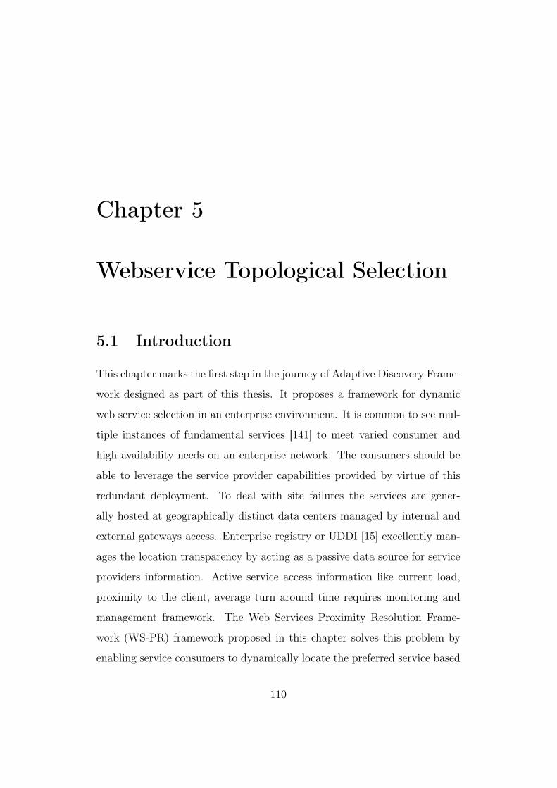
Chapter 5
Webservice Topological Selection
5.1 Introduction
This chapter marks the first step in the journey of Adaptive Discovery Frame-
work designed as part of this thesis. It proposes a framework for dynamic
web service selection in an enterprise environment. It is common to see mul-
tiple instances of fundamental services [141] to meet varied consumer and
high availability needs on an enterprise network. The consumers should be
able to leverage the service provider capabilities provided by virtue of this
redundant deployment. To deal with site failures the services are gener-
ally hosted at geographically distinct data centers managed by internal and
external gateways access. Enterprise registry or UDDI [15] excellently man-
ages the location transparency by acting as a passive data source for service
providers information. Active service access information like current load,
proximity to the client, average turn around time requires monitoring and
management framework. The Web Services Proximity Resolution Frame-
work (WS-PR) framework proposed in this chapter solves this problem by
enabling service consumers to dynamically locate the preferred service based
110

CHAPTER 5. WEBSERVICE TOPOLOGICAL SELECTION 111
on the active proximity information. The framework computes this informa-
tion using both topological and end point location of service providers and
consumers. The next section explains the framework, its key components
and the interaction of these components using UDDI.
5.2 Web Services Proximity Resolution Frame-
work
Figure 5.1 explains the information flow in an enterprise using the proposed
Webservice-Proximity Resolution Framework . The figure indicates a client
X looking for a service offering of type S1. The service S1 is hosted at three
distinct sites each one of which is located at a geographical distinct loca-
tion. The system consists of four network elements D1,D2,D3 and D4 which
connects various data centers containing the Service Provider. The client in-
teracts with UDDI registry for obtaining WSDL [142]. This WSDL contains
the topological metadata. As part of this framework a new service provider
is introduced called Network Topological Information Service (NTIS). NTIS
is the backbone of this framework. It computes and provides necessary topo-
logical preference information to the service consumer. The information flow
between the participating entities can be explained in four steps:
Step1: Interaction with UDDI The service consumer contacts the UDDI
registry for the service endpoints. The UDDI registry returns service
description annotated with specialized topological metadata.
Step2: Interaction with NTIS The service consumer interacts with NTIS
providing its requirement and metadata information. NTIS server com-
putes the proximity list using the service provider information provided

CHAPTER 5. WEBSERVICE TOPOLOGICAL SELECTION 112
DataCenter 1
DataCenter 2
Router Located At HQ
D4
Router D1
Router D2
DataCenter 3
Router D3
Service Host 2 Service Host 3
WebService Client
UDDI Service Registry
Step 1. Interaction with Uddi Service
NTIS
Step 2. Interaction with NTIS
Step 3: Interaction with Service
R1
R2
R3
Service Host 1
S1
S1 S1
Figure 5.1: Sample Topology of Network

CHAPTER 5. WEBSERVICE TOPOLOGICAL SELECTION 113
by the client and respond to the client with the same.
The client uses the information provided in Step 2 to invoke the closest
service .This framework further provides a mechanism for routing to the
nearest server using NTIS service proximity list. The next section explains
Network Topological Information Service, that is the pivotal part of this
framework.
5.3 Network Topological Information Service
Network Topological information service (NTIS) is a core of this architecture.
The web service interface provided by this service enables consumers to reach
to the nearest service provider. The interface consist of the consumer loca-
tion information and the list of sites the service nodes are associated with.
The service consumer needs to be aware of its location in the network. It
obtains the provider site location from the UDDI metadata. The consumer
need to contact NTIS with this information. The topological information is
encapsulated in NTIS using Network Topology language. The next section
explains the structure of Network Topology Description explained used in
this chapter.
5.3.1 Network Topology Description
Enterprise environment is controlled with predefined or less fluid network
topology. The framework used Network Topology Description(NDL) for
modeling enterprise network topology. In order to use standard based ap-
proach for topology description network topology is described using RDF[143]
[144] as specified in Network topology language[20]. The elements of the Net-
work Topology Ontology language are explained below:

CHAPTER 5. WEBSERVICE TOPOLOGICAL SELECTION 114
Location : A Physical location/site/room where the hardware is place.
Device : A network connected entity which is connected to other ele-
ments of the network. This can be a Router/Machine.
Interface: A Network Connection which connects Devices together.
Attributes of Location: A location as a name associated with it. It can
also optionally be associated with a geographical data like latitude and
longitude.
Attributes of Device: A Device is located at a site. And is connected to
other devices using multiple interface.
Attributes of Interface: An Interface is a connection between 2 devices
and also has a name associated with it.
Listing 6.1 provides the Network topology language RDF for the Fig 5.1
network structure.
<?xml version="1.0" encoding="UTF−8"?>
<rdf:RDF xmlns:rdf="http://www.w3.org/1999/02/22−rdf−
syntax−ns#" xmlns:ndl="http://www.science.uva.nl/research/
air/ndl#">
<ndl:Location rdf:about="#HQ">
<ndl:name>HeadQuarters</ndl:name>
</ndl:Location>
<ndl:Location rdf:about="#DataCenter1">
<ndl:name>DataCenter1</ndl:name>
</ndl:Location>
<ndl:Location rdf:about="#DataCenter2">
<ndl:name>DataCenter2</ndl:name>
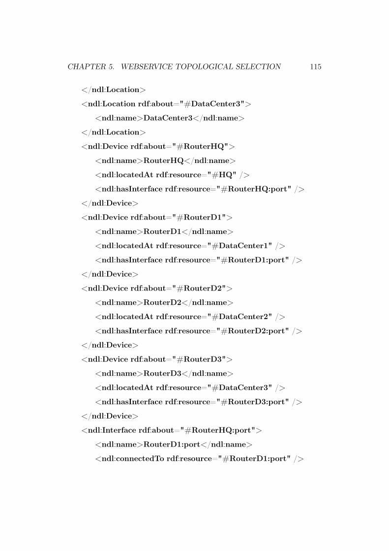
CHAPTER 5. WEBSERVICE TOPOLOGICAL SELECTION 115
</ndl:Location>
<ndl:Location rdf:about="#DataCenter3">
<ndl:name>DataCenter3</ndl:name>
</ndl:Location>
<ndl:Device rdf:about="#RouterHQ">
<ndl:name>RouterHQ</ndl:name>
<ndl:locatedAt rdf:resource="#HQ" />
<ndl:hasInterface rdf:resource="#RouterHQ:port" />
</ndl:Device>
<ndl:Device rdf:about="#RouterD1">
<ndl:name>RouterD1</ndl:name>
<ndl:locatedAt rdf:resource="#DataCenter1" />
<ndl:hasInterface rdf:resource="#RouterD1:port" />
</ndl:Device>
<ndl:Device rdf:about="#RouterD2">
<ndl:name>RouterD2</ndl:name>
<ndl:locatedAt rdf:resource="#DataCenter2" />
<ndl:hasInterface rdf:resource="#RouterD2:port" />
</ndl:Device>
<ndl:Device rdf:about="#RouterD3">
<ndl:name>RouterD3</ndl:name>
<ndl:locatedAt rdf:resource="#DataCenter3" />
<ndl:hasInterface rdf:resource="#RouterD3:port" />
</ndl:Device>
<ndl:Interface rdf:about="#RouterHQ:port">
<ndl:name>RouterD1:port</ndl:name>
<ndl:connectedTo rdf:resource="#RouterD1:port" />

CHAPTER 5. WEBSERVICE TOPOLOGICAL SELECTION 116
<ndl:connectedTo rdf:resource="#RouterD2:port" />
</ndl:Interface>
<ndl:Interface rdf:about="#RouterD1:port">
<ndl:name>RouterD1:port</ndl:name>
<ndl:connectedTo rdf:resource="#RouterHQ:port" />
</ndl:Interface>
<ndl:Interface rdf:about="#RouterD2:port">
<ndl:name>RouterD1:port</ndl:name>
<ndl:connectedTo rdf:resource="#RouterHQ:port" />
<ndl:connectedTo rdf:resource="#RouterD3:port" />
</ndl:Interface>
<ndl:Interface rdf:about="#RouterD3:port">
<ndl:name>RouterD1:port</ndl:name>
<ndl:connectedTo rdf:resource="#RouterD2:port" />
</ndl:Interface>
</rdf:RDF>
Listing 5.1: Topology description for network in Fig 5.1 using Network
Topology Ontology Language.
The next section explains the NTIS interface provided for service con-
sumer.
5.3.2 NTIS interface for WS consumer
NTIS provides an interface for service consumer that accepts the list of service
locations. It internally maintains a graph representation of the network based
on the ontological description. Based on the location information of the
service, as obtained from the consumer, it provides the proximity list. It
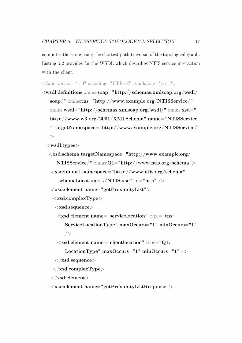
CHAPTER 5. WEBSERVICE TOPOLOGICAL SELECTION 117
computes the same using the shortest path traversal of the topological graph.
Listing 5.2 provides for the WSDL which describes NTIS service interaction
with the client.
<?xml version="1.0" encoding="UTF−8" standalone="yes"?>
<wsdl:definitions xmlns:soap="http://schemas.xmlsoap.org/wsdl/
soap/" xmlns:tns="http://www.example.org/NTISService/"
xmlns:wsdl="http://schemas.xmlsoap.org/wsdl/" xmlns:xsd="
http://www.w3.org/2001/XMLSchema" name="NTISService
" targetNamespace="http://www.example.org/NTISService/"
>
<wsdl:types>
<xsd:schema targetNamespace="http://www.example.org/
NTISService/" xmlns:Q1="http://www.ntis.org/schema">
<xsd:import namespace="http://www.ntis.org/schema"
schemaLocation="./NTIS.xsd" id="ntis" />
<xsd:element name="getProximityList">
<xsd:complexType>
<xsd:sequence>
<xsd:element name="servicelocation" type="tns:
ServiceLocationType" maxOccurs="1" minOccurs="1"
/>
<xsd:element name="clientlocation" type="Q1:
LocationType" maxOccurs="1" minOccurs="1" />
</xsd:sequence>
</xsd:complexType>
</xsd:element>
<xsd:element name="getProximityListResponse">

CHAPTER 5. WEBSERVICE TOPOLOGICAL SELECTION 118
<xsd:complexType>
<xsd:sequence>
<xsd:element name="locationProximityData" type="tns:
locationProximityDataType" />
</xsd:sequence>
</xsd:complexType>
</xsd:element>
<xsd:complexType name="ServiceLocationType">
<xsd:sequence>
<xsd:element name="site" type="Q1:LocationType" />
</xsd:sequence>
</xsd:complexType>
<xsd:complexType name="locationProximityDataType">
<xsd:sequence>
<xsd:element name="locationProximity" type="Q1:
LocationProximityType" maxOccurs="unbounded"
minOccurs="0" />
</xsd:sequence>
</xsd:complexType>
</xsd:schema>
</wsdl:types>
<wsdl:message name="getProximityListRequest">
<wsdl:part element="tns:getProximityList" name="
parameters" />
</wsdl:message>
<wsdl:message name="getProximityListResponse">

CHAPTER 5. WEBSERVICE TOPOLOGICAL SELECTION 119
<wsdl:part element="tns:getProximityListResponse" name="
parameters" />
</wsdl:message>
<wsdl:portType name="NTISService">
<wsdl:operation name="getProximityList">
<wsdl:input message="tns:getProximityListRequest" />
<wsdl:output message="tns:getProximityListResponse" />
</wsdl:operation>
</wsdl:portType>
<wsdl:binding name="NTISServiceSOAP" type="tns:
NTISService">
<soap:binding style="document" transport="http://schemas.
xmlsoap.org/soap/http" />
<wsdl:operation name="getProximityList">
<soap:operation soapAction="http://www.example.org/
NTISService/getProximityList" />
<wsdl:input>
<soap:body use="literal" />
</wsdl:input>
<wsdl:output>
<soap:body use="literal" />
</wsdl:output>
</wsdl:operation>
</wsdl:binding>
<wsdl:service name="NTISService">
<wsdl:port binding="tns:NTISServiceSOAP" name="
NTISServiceSOAP">
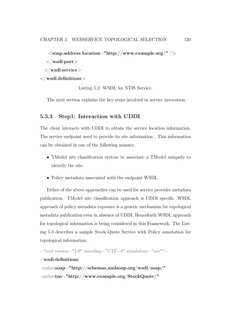
CHAPTER 5. WEBSERVICE TOPOLOGICAL SELECTION 120
<soap:address location="http://www.example.org/" />
</wsdl:port>
</wsdl:service>
</wsdl:definitions>
Listing 5.2: WSDL for NTIS Service.
The next section explains the key steps involved in service invocation.
5.3.3 Step1: Interaction with UDDI
The client interacts with UDDI to obtain the service location information.
The service endpoint need to provide its site information . This information
can be obtained in one of the following manner.
• TModel site classification system to associate a TModel uniquely to
identify the site.
• Policy metadata associated with the endpoint WSDL
Either of the above approaches can be used for service provider metadata
publication. TModel site classification approach is UDDI specific .WSDL
approach of policy metadata exposure is a generic mechanism for topological
metadata publication even in absence of UDDI. Henceforth WSDL approach
for topological information is being considered in this Framework. The List-
ing 5.3 describes a sample Stock Quote Service with Policy annotation for
topological information.
<?xml version="1.0" encoding="UTF−8" standalone="yes"?>
<wsdl:definitions
xmlns:soap="http://schemas.xmlsoap.org/wsdl/soap/"
xmlns:tns="http://www.example.org/StockQuote/"

CHAPTER 5. WEBSERVICE TOPOLOGICAL SELECTION 121
xmlns:wsdl="http://schemas.xmlsoap.org/wsdl/"
xmlns:xsd="http://www.w3.org/2001/XMLSchema"
name="StockQuote"
xmlns:wsp="http://schemas.xmlsoap.org/ws/2004/09/policy"
targetNamespace="http://www.example.org/StockQuote/"
xmlns:wsu="http://docs.oasis−open.org/wss/2004/01/oasis
−200401−wss−wssecurity−utility−1.0.xsd"
xmlns:wsml="http://www.w3.org/Submission/WSML/" xmlns:
ntis="http://www.ntis.org/schema">
<wsp:Policy wsu:Id="LocationPolicy">
<ntis:location uri="http://servicehost1/service1" >ServiceHost
1</ntis:location>
<ntis:location uri="http://servicehost2/service1" >ServiceHost
2</ntis:location>
<ntis:location uri="http://servicehost3/service1" >ServiceHost
3</ntis:location>
</wsp:Policy>
<wsdl:types>
..........
..........
</wsdl:types>
...
<wsdl:service name="StockQuoteService">
<wsp:PolicyReference URI="#LocationPolicy" />
<wsdl:port binding="tns:StockQuoteServiceSOAP" name
="GetStockTrade">
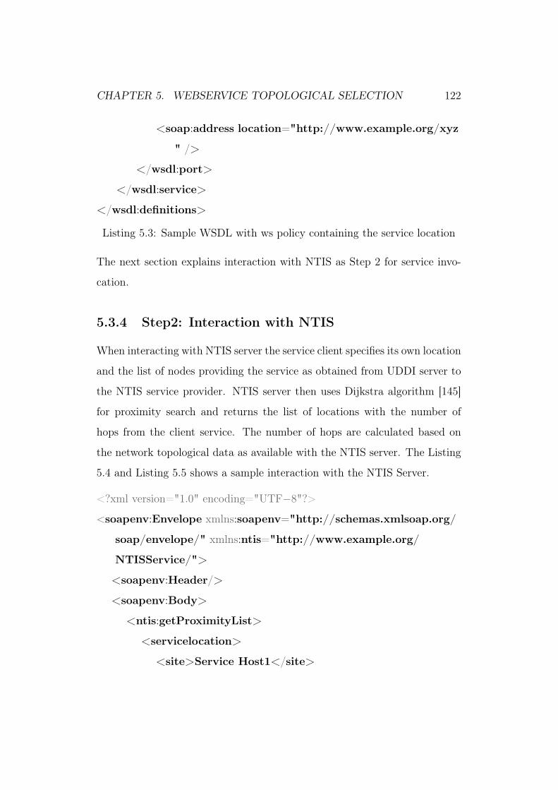
CHAPTER 5. WEBSERVICE TOPOLOGICAL SELECTION 122
<soap:address location="http://www.example.org/xyz
" />
</wsdl:port>
</wsdl:service>
</wsdl:definitions>
Listing 5.3: Sample WSDL with ws policy containing the service location
The next section explains interaction with NTIS as Step 2 for service invo-
cation.
5.3.4 Step2: Interaction with NTIS
When interacting with NTIS server the service client specifies its own location
and the list of nodes providing the service as obtained from UDDI server to
the NTIS service provider. NTIS server then uses Dijkstra algorithm [145]
for proximity search and returns the list of locations with the number of
hops from the client service. The number of hops are calculated based on
the network topological data as available with the NTIS server. The Listing
5.4 and Listing 5.5 shows a sample interaction with the NTIS Server.
<?xml version="1.0" encoding="UTF−8"?>
<soapenv:Envelope xmlns:soapenv="http://schemas.xmlsoap.org/
soap/envelope/" xmlns:ntis="http://www.example.org/
NTISService/">
<soapenv:Header/>
<soapenv:Body>
<ntis:getProximityList>
<servicelocation>
<site>Service Host1</site>

CHAPTER 5. WEBSERVICE TOPOLOGICAL SELECTION 123
<site>Service Host2</site>
<site>Service Host3</site>
</servicelocation>
<clientlocation>Client Host1</clientlocation>
</ntis:getProximityList>
</soapenv:Body>
</soapenv:Envelope>
Listing 5.4: Sample Request for NTIS Service
<soapenv:Envelope xmlns:soapenv="http://schemas.xmlsoap.org/
soap/envelope/" xmlns:ntis="http://www.example.org/
NTISService/" xmlns:sch="http://www.ntis.org/schema">
<soapenv:Header/>
<soapenv:Body>
<ntis:getProximityListResponse>
<locationProximityData>
<locationProximity>
<sch:location>Service Host1</sch:location>
<sch:proximity>1</sch:proximity>
</locationProximity>
<locationProximity>
<sch:location>Service Host2</sch:location>
<sch:proximity>2</sch:proximity>
</locationProximity>
<locationProximity>
<sch:location>Service Host3</sch:location>

CHAPTER 5. WEBSERVICE TOPOLOGICAL SELECTION 124
<sch:proximity>3</sch:proximity>
</locationProximity>
</locationProximityData>
</ntis:getProximityListResponse>
</soapenv:Body>
</soapenv:Envelope>
Listing 5.5: Sample Response for NTIS Service
Once NITS provides the list of sites based on the topological ordering.
Based on this information service client invokes the service endpoint. Client
can also invoke second or third service endpoint in ranking from the list
provided in case first one is not available or falters. This information is
persisted on the client for smaller durations to avoid repeated interaction
with NTIS. This cache should be refreshed after a fixed specified interval
to take advantage of the topological changes. Next section summarizes the
work done in this chapter.
5.4 Summary
This chapter explains the WS-PR framework that enables the pull model of
service discovery. Client can fetch the proximity information at regular in-
tervals for discovery based on the active information provided by the NTIS.
Encapsulating topological metadata in a centralized broker also provides a
secure way of preserving the network topological information. This is the
only repository that need to be modified to capture any site failure. Cen-
tralization of topological information in NTIS most importantly helps in cal-
culating and determining the proximity to service provider. It uses Dijkstra
algorithm on network graph represented by RDF to determine the ranking.

CHAPTER 5. WEBSERVICE TOPOLOGICAL SELECTION 125
This approach is interoperable and easy to adopt and support as it is based
on standards. From an enterprise deployment perspective, consumer need to
support NTIS Web Service transparently. This chapter solved the dynamic
discovery problem based on proximity as the quality attribute. In order to
support generic QoS attributes there is a need to provision a way to model
QoS information and relationship between its attributes. It should also be
able to express service provider QoS offering and client QoS requirements.
Not only that, there is a need for common glue to enable communication
among participating entities in the system. In order to achieve the same a
high-level domain specific language has been developed to enable QoS spec-
ification and communication in the SOA system. The next chapter explains
the language in detail.
Chapter 6
QoS DSL for Web Services
6.1 Introduction
The use of ontology and semantics promises ‘Proactive Services-Oriented En-
terprise’. Ontologies provides the next level of abstraction for knowledge rep-
resentation by encapsulating different information models in a domain using
concepts, axioms and relationships. They serve as the backbone for Seman-
tic Web [146], that foresees web as a mesh of information linked together
with contexts. The semantic standards when mapped to SOA yields Seman-
tic Web services (SWS) [147]. SWS are moving towards actual deployment.
The motivation for this semantically enabled linking of information behind
semantic web is to achieve automation, integration, and reuse of data across
various applications. Due to this ontologies are used for capabilities based
web services discovery and composition based on their capabilities and prop-
erties. Domain Ontologies are becoming a common norm for enterprise sys-
tems catering to a knowledge domain encompassing multiple problem areas.
It is recommended that enterprises [148] should move towards the semantics
journey in a pragmatic manner to support adaptive ontological growth. This
126
CHAPTER 6. QOS DSL FOR WEB SERVICES 127
can be enabled by using light-weight ontologies that can be linked together to
avoid the development of complex data structures. In the words of Simperl
et al. [149] :
"... ontology engineering research should strive for a unified,
lightweight and component-based methodological framework, prin-
cipally targeted at domain experts ...."
Two common ontologies exist in the form of WSMO [150] and OWL-
S [151] to offer service description. Both of them provide a rich model to
describe SWS functionalities but they offer few restricted QoS concepts to
express their qualities. Many works have extended them to obtain QoS-aware
ontologies. For example the Web Service Modeling Language (WSML) [152]
framework provides a proposed mechanism to specify both functional and
nonfunctional aspects of WSMO. QoS is not central to WSML and its def-
inition using nonfunctional properties and rule syntax is quite complex. In
this work a high-level domain specific language (DSL) written in groovy is
defined by extending WSMO. The use of high-level language enables quick
adoption and fast development due its light-weight nature. It is based on
constraint programming[153] ideas and provide a verbose syntactical mech-
anism for defining QoS constraints. The next section explains the DSL and
its elements in detail.
6.2 Domain Specific Language
QoS specification language(QSL) is created as an embedded DSL for Groovy
for the purpose of using it as a light-weight mechanism to communicate
QoS capabilities and constraints to enable QoS-aware web service discovery.

CHAPTER 6. QOS DSL FOR WEB SERVICES 128
Groovy [154] is a dynamic language written using Java [155]. It provides a
mechanism to write embedded DSL [156].The use of standard language also
ensures that conditions on QoS constraints can be easily expressed without
the need for an elaborate grammar as in WSML Rule Syntax [152]. The user
can use standard java or groovy Syntax interchangeably. To be interoperable
the syntax is being kept closer to ontological hierarchy of WSML structure.
Next section explains the needs to be fulfilled by QSL language.
6.2.1 QSL Syntax
At first it is required to identify the requirements that need to be fulfilled by
the language. As a next step syntax is defined based on these requirements.
The key needs to be fulfilled are as follows:
• Defining QoS parameters that need to be supported by the Web Service.
QosConcept tags is used to define the same.
• Declaration of Web services provider that can define expected/observed
values of QoS parameters. QosWebService tag is used for QoS values.
• Specification of goals or conditions, that need to be satisfied for a web
service consumer. QosAxiom is used to define the actual conditions on
QoS parameters. QosGoal is used to associate web service client with
a set of conditions or axioms.
While designing the language, a special focus has been kept on ease of
syntax. The key features that the language exhibits are; separation of multi-
ple statement using newline, and use of equal to sign between property name
and its value to separate them. The various keywords are followed by curly
brackets. The language is defined based on various important pieces of DSL

CHAPTER 6. QOS DSL FOR WEB SERVICES 129
syntax and elements of QoS characteristics for which parameters need to be
found are as follows. The syntax of the language is defined as follows:
• QosLanguage
This keyword forms external most qualifier which is used to assert the
presence of QoS constraint language. The line 1 in Listings 6.1 defines
the outer QosLanguage tag.
• QosConcept.
The QosConcept is used to define QoS parameter/characteristics. It
is an important element since it defines the parameters on which QoS
selection is based. The concept is used to define both functional and
non functional parameters like availability and security. The lines 3 to
9 in Listings 6.1 defines the QosConcept. The various parameters that
are defined as part of QoSConcept are as follows
– description
A verbal comment on the content of this tag.
– name
unique name to identify this particular QoSConcept.
– dataType
defines the datatype used to represent this QoSConcept.
This Datatype should be a well defined Groovy Datatype(or Java
datatype).
– lowerBound
defines the lower expectable bound on the value of this QoS pa-
rameter. The value is defined as a String and it is converted into
dataType unit.

CHAPTER 6. QOS DSL FOR WEB SERVICES 130
– upperBound defined the upper threshold value on this parameter.
• QosWebService
QosWebservice tag is used to define actual web service and associates
value for each QoS concept. This parameter is used for binding QoS
language to actual web services provider. Elaborate mechanism need to
be developed for mapping the data to WSDL or UDDI based systems.
The lines 11 to 20 in Listings 6.1 defines the QosWebService. The
various parameter are as follows:-
– description
A verbal comment on the content of this tag.
– name
unique name to identify this particular WebService.
– capability
Use to associate web service interface with this tag.
– qosinterface
Embedded tag inside web service which is used to specify values
for actual QOS concepts.
A nested tag, which contains one tag for each of QoSConcept. The
rough syntax for QosInterface is provided in listing 6.1.
• QosAxiom
The QosAxiom forms the center piece of QoS Language. It is used
to define conditions on QoS parameters. Condition on QoSAxiom is
defined as a closure. It contains a groovy syntax for defining a con-
dition statement on passed value of the concept "Availability". The
CHAPTER 6. QOS DSL FOR WEB SERVICES 131
term axiom is chosen from WSML ontology to provide for easy inter-
operability. The lines 22 to 29 in Listings 6.1 defines the QosAxiom.
The parameters for QosAxiom are as follows:-
– description
A verbal comment on the content of this axiom.
– name
Specifies a unique name to identify this axiom.
– concept
name of the QosConcept on which on which conditions are defined.
– condition
Closure structure to define actual condition for verification.
Condition tag needs some further discussion. This tag contains a Clo-
sure which must return a boolean value which is true or false. That
implies, that the last statement in this Groovy block must evaluate to
true or false. And since this is a groovy block, user can write a valid
groovy code to define the condition. One explicit value, which is the
current QoS concept value of a known web service is passed to this
closure.
• QosGoal
QosGoal is used to define requirements of web service consumer. It de-
fines the conditions that web service consumer requires to be satisfied.
The actual set of condition on individual QoS parameters is defined
as part of QoSAxioms..The lines 31 to 35 in Listings 6.1 defines the
QosGoal. The goals are used to specify set of axioms that need to be
satisfied as part of this web service consumer
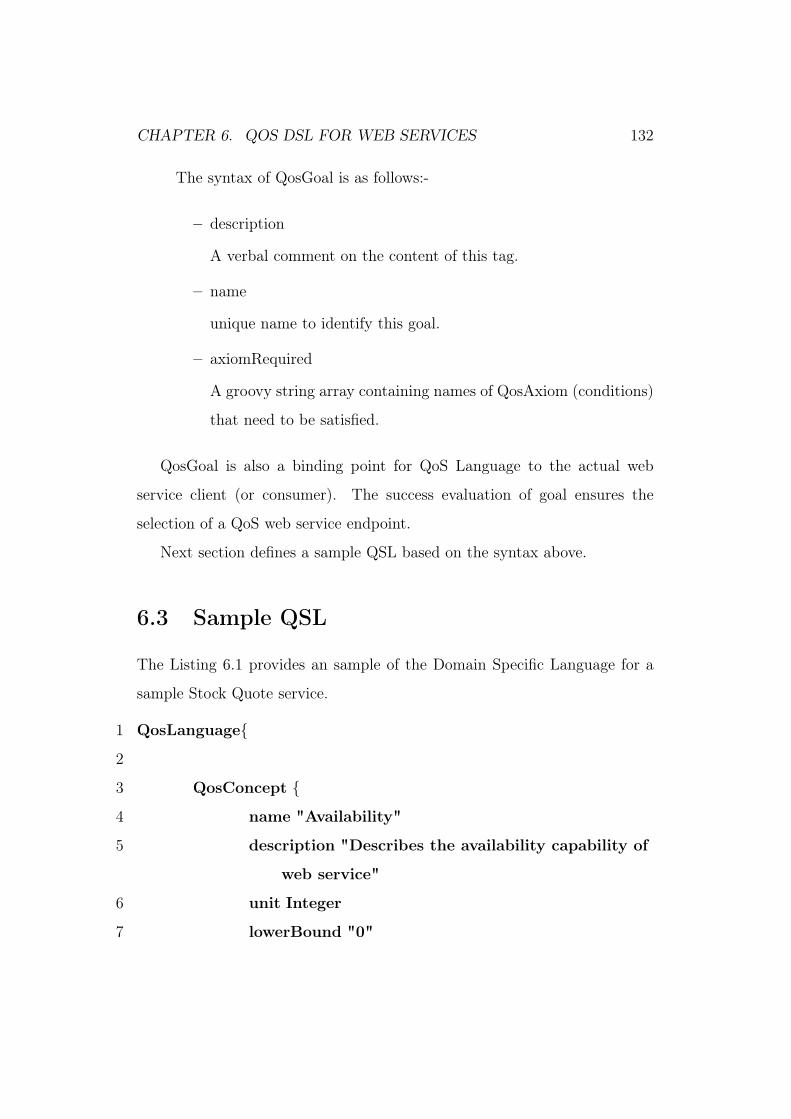
CHAPTER 6. QOS DSL FOR WEB SERVICES 132
The syntax of QosGoal is as follows:-
– description
A verbal comment on the content of this tag.
– name
unique name to identify this goal.
– axiomRequired
A groovy string array containing names of QosAxiom (conditions)
that need to be satisfied.
QosGoal is also a binding point for QoS Language to the actual web
service client (or consumer). The success evaluation of goal ensures the
selection of a QoS web service endpoint.
Next section defines a sample QSL based on the syntax above.
6.3 Sample QSL
The Listing 6.1 provides an sample of the Domain Specific Language for a
sample Stock Quote service.
1 QosLanguage
2
3 QosConcept
4 name "Availability"
5 description "Describes the availability capability of
web service"
6 unit Integer
7 lowerBound "0"

CHAPTER 6. QOS DSL FOR WEB SERVICES 133
8 upperBound "100"
9
10
11 QosWebService
12 name "webserviceQos"
13 capability "StockQuoteWS"
14 qosinterface
15 Availability
16 description " availability description"
17 value "8"
18
19
20
21
22 QosAxiom
23 name "myQosCondition"
24 concept "Availability"
25 description "Describe the mechanism of comparing
the availability"
26 condition$value −>
27 return (value > 50)
28
29
30
31 QosGoal
32 description "Goals we wanted to achieve"
33 name "goalWeb"
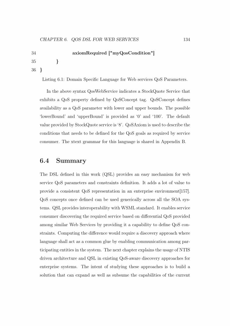
CHAPTER 6. QOS DSL FOR WEB SERVICES 134
34 axiomRequired ["myQosCondition"]
35
36
Listing 6.1: Domain Specific Language for Web services QoS Parameters.
In the above syntax QosWebService indicates a StockQuote Service that
exhibits a QoS property defined by QoSConcept tag. QoSConcept defines
availability as a QoS parameter with lower and upper bounds. The possible
‘lowerBound’ and ‘upperBound’ is provided as ‘0’ and ‘100’. The default
value provided by StockQuote service is ‘8’. QoSAxiom is used to describe the
conditions that needs to be defined for the QoS goals as required by service
consumer. The xtext grammar for this language is shared in Appendix B.
6.4 Summary
The DSL defined in this work (QSL) provides an easy mechanism for web
service QoS parameters and constraints definition. It adds a lot of value to
provide a consistent QoS representation in an enterprise environment[157].
QoS concepts once defined can be used generically across all the SOA sys-
tems. QSL provides interoperability with WSML standard. It enables service
consumer discovering the required service based on differential QoS provided
among similar Web Services by providing it a capability to define QoS con-
straints. Computing the difference would require a discovery approach where
language shall act as a common glue by enabling communication among par-
ticipating entities in the system. The next chapter explains the usage of NTIS
driven architecture and QSL in existing QoS-aware discovery approaches for
enterprise systems. The intent of studying these approaches is to build a
solution that can expand as well as subsume the capabilities of the current

CHAPTER 6. QOS DSL FOR WEB SERVICES 135
deployments.

Chapter 7
QoS-aware Discovery Mechanism
7.1 Introduction
Sustainability in operational business is an important criteria for enterprises
to evolve or adopt any innovation. Keeping this essential need of run-the-
business for enterprises, this chapter studies and shares the resulting flow of
using NTIS [18] and QSL [19] in existing state of QoS-aware SOA deploy-
ments. To enlist some of the very common use cases of redundancy for these
QoS-aware systems are as follows:
1.) Reusability [158] is one of the key reasons for enterprise SOA deploy-
ments. A single service can be re-used in different application and can
be accessed by different consumers. These consumers may have differ-
ent QoS requirements from the same service. For example: An appli-
cation would prefer to use services either co-located or in closer data
centers while building composite application for higher performance.
2.) Services are used across organizational units [127] which means if it is
developed by one business unit it should be exposed across it bound-
136

CHAPTER 7. QOS-AWARE DISCOVERY MECHANISM 137
aries to be re-used by other organizational entities and units. A service
provider may provide multiple end-point to segregate users across busi-
ness unit boundaries .
3.) Services may also be replicated to meet differential operational cost. If
cost gets varied due location of data centers, service provider would
like to replicate the same to less-cost location.
4.) The same implementation of service may be redundantly deployed to
cater to provide differential QoS requirements. The demand for these
requirements may change based on-the-fly or planned depending on the
needs.
However the level of maturity of these QoS-aware deployments are not
same across enterprises. The next section discusses the two most viable
QoS-aware service discovery approaches in current enterprise scenarios. It
explains the information flow and interaction diagram of these approaches,
when adding NTIS and QSL to support the discovery approach. It shares
the results of enhanced ESB based discovery architecture leveraging NTIS
and QSL.
7.2 Service Discovery Approaches
Both Network Topological Information Service(NTIS) and Query Specifica-
tion Language (QSL) shall be used to create a framework for QoS-aware dy-
namic discovery for existing service deployments. NTIS server can be used
to define and centrally manage QoS concepts, that client and service can
use to negotiate. The service provider defines QoS assertions and provides
the same to NTIS server .The clients provides the axioms and goals along

CHAPTER 7. QOS-AWARE DISCOVERY MECHANISM 138
with topological location, that is used by the NTIS server to find and rank
the suitable services. These services are filtered and ranked based on QoS
constraints leveraging topological metadata. The information flow shall vary
based on the SOA stack deployment maturity. The next section explains the
most fundamental QoS-aware discovery approach in the enterprise systems.
7.2.1 Blind Belief QoS Assertions Discovery
In this mechanism the client blindly believes on the QoS assertions declared
by the services during bootstrap. To achieve the same using NTIS, the ser-
vice provider will declare its QoS capabilities either at bootstrap or off-band
through manual entry in the NTIS information repository. The client re-
quests services based on its QoS requirements. The client blindly believes on
the declared QoS assertions from the service provider, it is henceforth named
as ‘Blind Belief’. The service ranking is obtained based on the declared QoS
constraints from the service. It may not be the most effective mechanism
for handling QoS discovery but plays a critical role to begin with deploying
a QoS aware environment. In other words this methodology provides low
entry bar for legacy or older services [117] without re-writing the same. As
a result it allows for fast QoS adoption with varied degree of QoS maturity
[159, 117] in the enterprise. The Figure 7.1 indicates the QoS Assertions
(QA) declared by all the services being send to NTIS during bootstrap and
QoS Requirements (QR) being provided by the client to NTIS. .
The diagram in Figure 7.2 further explains the sequence of interaction
between different components. As a first step client queries NTIS for service
information specifying its requirement for QoSGoals and current location
to calculate the service proximity. NTIS then returns the ranked service
information as a response to the client. Henceforth client interacts with the

CHAPTER 7. QOS-AWARE DISCOVERY MECHANISM 139
1
Figure 7.1: Blind Belief Discovery Mechanism
corresponding service based on relative ranking obtained. In this mechanism
the ranking is computed by NTIS based on the information provided by the
service provider and QoS requirements of the client without any run-time
feedback and dynamic monitoring of the system. The client believes on the
information provided.
The next section explains the discovery mechanism that measures the
changing QoS at run-time during client service interaction using Enterprise
Service Bus (ESB).
7.2.2 Measured QoS assertions Discovery
In this mechanism QoS assertion as declared by the service will be measured
via middleware component known as Enterprise Service Bus (ESB) [111].
ESB is one of the most commonly used component in the SOA deployment
stack. It provides mediation, transformation, routing of messages among
different components in the SOA system [117]. Since it sits in the middle
client and server perform each communication via ESB. The ESB acts as
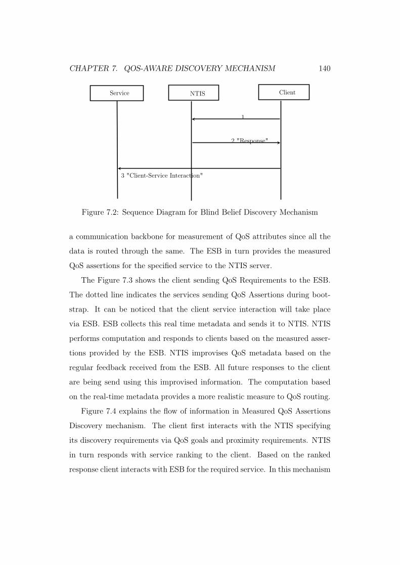
CHAPTER 7. QOS-AWARE DISCOVERY MECHANISM 140
Service NTIS Client
1
2 "Response"
3 "Client-Service Interaction"
Figure 7.2: Sequence Diagram for Blind Belief Discovery Mechanism
a communication backbone for measurement of QoS attributes since all the
data is routed through the same. The ESB in turn provides the measured
QoS assertions for the specified service to the NTIS server.
The Figure 7.3 shows the client sending QoS Requirements to the ESB.
The dotted line indicates the services sending QoS Assertions during boot-
strap. It can be noticed that the client service interaction will take place
via ESB. ESB collects this real time metadata and sends it to NTIS. NTIS
performs computation and responds to clients based on the measured asser-
tions provided by the ESB. NTIS improvises QoS metadata based on the
regular feedback received from the ESB. All future responses to the client
are being send using this improvised information. The computation based
on the real-time metadata provides a more realistic measure to QoS routing.
Figure 7.4 explains the flow of information in Measured QoS Assertions
Discovery mechanism. The client first interacts with the NTIS specifying
its discovery requirements via QoS goals and proximity requirements. NTIS
in turn responds with service ranking to the client. Based on the ranked
response client interacts with ESB for the required service. In this mechanism

CHAPTER 7. QOS-AWARE DISCOVERY MECHANISM 141
Client ESB
S1
S3
S2
NTISQoS
Analyzer
Figure 7.3: Measured QoS Assertions Discovery Mechanism
ESB asynchronously communicates the metrics to the NTIS server at regular
intervals. NTIS server uses this metrics to evaluate QoSAxiom.
Dynamic monitoring is a most adopted approach to capture changing
QoS characteristics [160]. Measured QoS Assertion achieved the same using
ESB. The next section demonstrates the sample execution run for Measured
QoS Assertion Discovery mechanism.
7.3 Sample for Measured QoS Assertion
In order to demonstrate the working of Measure QoS assertion approach with
NTIS the architecture WS-PR framework [18] is extended using ESB as a
middleware. The Figure 7.5 shows the extended architecture where all the
client service interactions are taking place via. ESB.
The next section explains the invocation details about service interaction
with NTIS and ESB architecture for the Figure 7.5.

CHAPTER 7. QOS-AWARE DISCOVERY MECHANISM 142
Client NTIS Service ESB
1
3"Interaction via ESB"
"Measured QoS assertions"
2
4
"Response"5
Figure 7.4: Sequence Diagram for Measured QoS Assertions Discovery Mech-anism
7.3.1 Service interaction with NTIS
Service providers sends QoS information to NTIS during bootstrap. This
information gets updated based on the inputs obtained from QoS analyzer.
For any new service on-boarded bootstrap message will act as first set of
inputs for QoS information. Service S1, S2 and S3 are Purchase Order ser-
vices. Each service will inform its endpointURI and topological location to
NTIS along with QoS offers. QoSWebService defines expected/observed QoS
values for Web Service provider along with service characteristics defined as
name, capability, endpointURI and topological location. These service char-
acteristics identify and characterize the service. This value is associated with
set of QoS interfaces which define QoS concepts. For service S1 message on
the network is shown in Listing 7.1. Name of the service is ’POService’ and
its capability is ’PurchaseOrder’. EndpointURI defines deployed endpoint

CHAPTER 7. QOS-AWARE DISCOVERY MECHANISM 143
DataCenter 1
DataCenter 2
Router Located At HQ
D4
Router D1
Router D2
DataCenter 3
Router D3
Service Host 2 Service Host 3
WebService Client
UDDI Service Registry
Step 1. Interaction with Uddi Service
NTIS
Step 3. Interaction with NTIS
Step 2: Interaction with ESB
R1
R2
R3
Service Host 1
S1
S1 S1
Enterprise Service Bus
Step 4: Interaction with Service
C 1
C 2
Data Flow
Network Route
Figure 7.5: ESB Enabled framework

CHAPTER 7. QOS-AWARE DISCOVERY MECHANISM 144
location URI of the service whereas the tag ’topologylocation’ defines topol-
ogy location of the service as defined using NDL in [18]. Service S1 offers
an availability of 90, has endpointURI e1 and topologylocation tS1. Next
section describes client interaction with PurchaseOrder service.
1 <?xml version="1.0"?>
2 <soap:Envelope xmlns:soap="http://schemas.xmlsoap.org/soap/
envelope/"
3 xmlns:xsi="http://www.w3.org/2001/XMLSchema−instance"
4 xmlns:xsd="http://www.w3.org/2001/XMLSchema"
5 xmlns:ntis="http://www.example.org">
6 <soap:Header/>
7 <soap:Body>
8 <ntis:QoSWebService>
9 <name>POService</name>
10 <capability>PurchaseOrder</capability>
11 <endpointuri>e1</endpointuri>
12 <topologylocation>tS1</topologylocation>
13 <qosinterfaces>
14 <interface>
15 <type>Availability</type>
16 <value>90</value>
17 </interface>
18 </qosinterfaces>
19 </ntis:QoSWebService>
20 </soap:Body>
21 </soap:Envelope>
Listing 7.1: Message for Service NTIS interaction

CHAPTER 7. QOS-AWARE DISCOVERY MECHANISM 145
The next section explains the consumer interaction with ESB.
7.3.2 Consumer Interaction with ESB
Client communicates with ESB specifying its QoS goals along with topo-
logical information. ESB interacts with NTIS to fetch and route request to
service based on ranking information obtained from NTIS. ESB adaptively
manages system by routing request to next available service in case higher
rank service is not available or heavily loaded. The message for client ESB
interaction will be as shown in Listing 7.2.
1 <?xml version="1.0"?>
2 <soap:Envelope
3 xmlns:soap="http://schemas.xmlsoap.org/soap/envelope/"
4 xmlns:xsi="http://www.w3.org/2001/XMLSchema−instance"
5 xmlns:xsd="http://www.w3.org/2001/XMLSchema"
6 xmlns:ntis="http://www.example.org">
7 <soap:Header/>
8 <soap:Body>
9 <getProximityList>
10 <serviceidentifier>sid1</serviceidentifier>
11 <clientlocation>tc1</clientlocation>
12 <qosgoal>
13 <description>manadatorygoals</description>
14 <type>mandatory</type>
15 <name>PurchaseOrder</name>
16 <axiomrequired>availability.greater.70,rtt.less.3sec </
axiomrequired>
17 </qosgoal>

CHAPTER 7. QOS-AWARE DISCOVERY MECHANISM 146
18 </getProximityList>
19 </soap:Body>
20 </soap:Envelope>
Listing 7.2: Consumer Interaction with ESB
It invokes an operation with the name getProximityList. This operation
specifies service identifier which identifies the service. In this case servicei-
dentifier is ’sd1’ for service S1. Clients also need to provide its topology
location. In this case it is tc1 for client C1. In alignment with QoS DSL
QosGoal specified client requirement using a set of axioms. Client C1 re-
quires availability greater than 70 and round trip time less than 3 sec. The
next section details the results obtained using RTT as a client QoS goals.
7.4 Results and Experimental set-up
This experimental set up is simulated to calculate Round Trip Time (RTT)
for both the clients C1 and C2 for sample enterprise topology shown in Figure
7.5. In the figure S1, S2 and S3 are redundant services located in three
different data centers. Client C1 is co-located with S1 and C2 with S2.
Clients C1 and C2 specify their QoS goals using QSL to ESB. Similarly S1,
S2 and S3 inform NTIS about QoS assertions using QSL during bootstrap. In
order to understand the impact of client and service topological location both
C1 and C2 are being located at different data centers. They both request
‘Purchase Order’ service with the same QoS goals. Services S1 and S2 offer
availability of 90 but service S3 offers availability of 60. First execution
sequence is done without using NTIS followed by second execution sequence
with NTIS. To evaluate the impact, it is assumed that no other redundancy
management technique at application or hardware. UDDI is assumed to
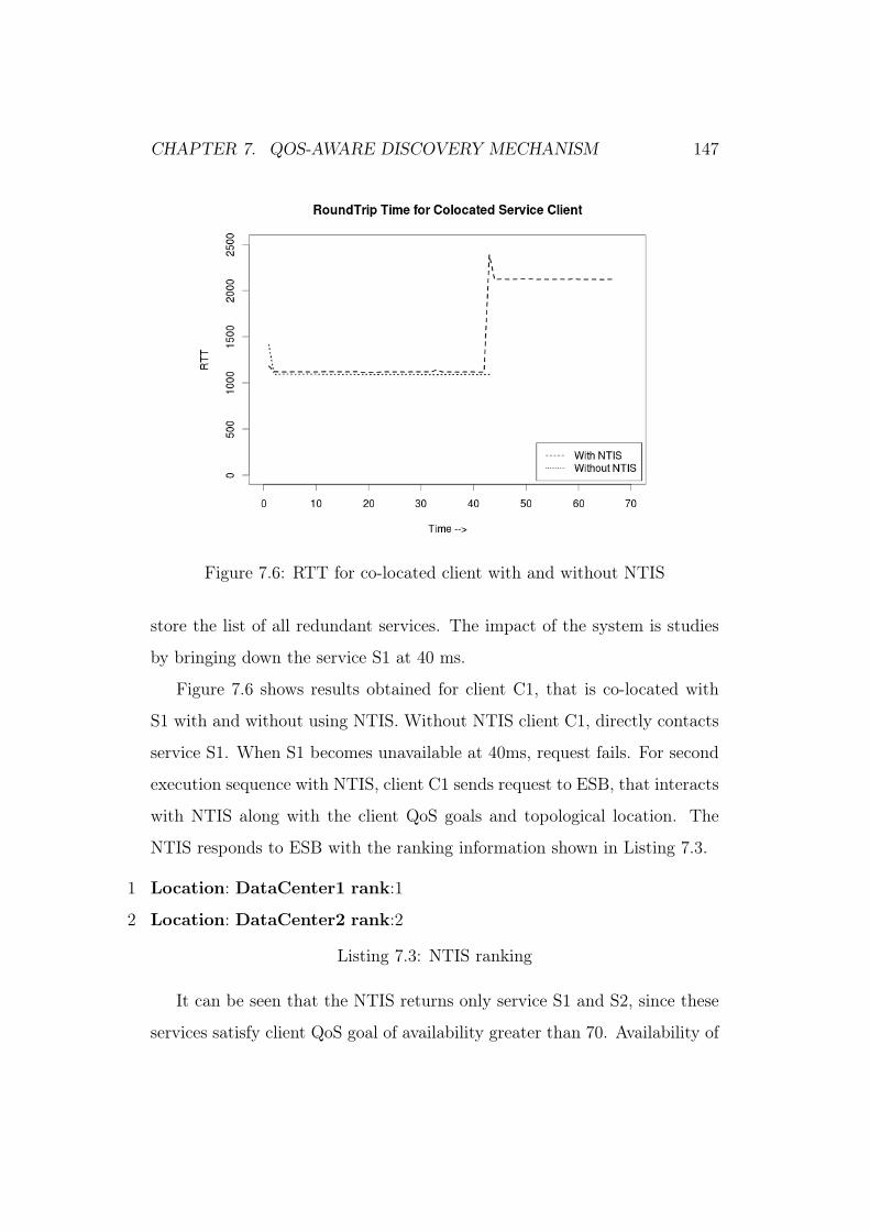
CHAPTER 7. QOS-AWARE DISCOVERY MECHANISM 147
Figure 7.6: RTT for co-located client with and without NTIS
store the list of all redundant services. The impact of the system is studies
by bringing down the service S1 at 40 ms.
Figure 7.6 shows results obtained for client C1, that is co-located with
S1 with and without using NTIS. Without NTIS client C1, directly contacts
service S1. When S1 becomes unavailable at 40ms, request fails. For second
execution sequence with NTIS, client C1 sends request to ESB, that interacts
with NTIS along with the client QoS goals and topological location. The
NTIS responds to ESB with the ranking information shown in Listing 7.3.
1 Location: DataCenter1 rank:1
2 Location: DataCenter2 rank:2
Listing 7.3: NTIS ranking
It can be seen that the NTIS returns only service S1 and S2, since these
services satisfy client QoS goal of availability greater than 70. Availability of

CHAPTER 7. QOS-AWARE DISCOVERY MECHANISM 148
Figure 7.7: RTT for remote client with and without NTIS
S3 is 60, hence it got eliminated in ranking. NTIS ranks S1 with rank1 and
S2 with rank2 for RTT, that should be the case as well since S1 and C1 are
co-located. ESB therefore routed C1 to S1. Figure 7.6 also indicates behavior
of SST independent of using NTIS. RTT remains same for co-located client
till both the services are available. When service S1 becomes C1 connects to
next possible ranked service.
Figure 7.7 shows behavior of RTT for client C2. Client C2 is remotely
located to S1 and is co-located with S2. Without NTIS, client C2 connects
with service S1, since it is first available service returned from UDDI. It sees
a larger RTT of 2200 ms and no re-routing in case of failure. With AQDF
C2 contacted S2 based on ranking determined by NTIS as shown on Listing
7.4 .
1 Location: DataCenter2 rank:1

CHAPTER 7. QOS-AWARE DISCOVERY MECHANISM 149
2 Location: DataCenter1 rank:2
Listing 7.4: NTIS ranking for C2
In case of failure ESB routes it to service S1, which is next available service in
ranking. One can see obvious advantage of high availability, faster response
time and fault-tolerance with ESB architecture. This experiment demon-
strated that correct identification, ranking and routing the services based on
client selection criteria. It also eliminates services not satisfying client QoS
goals and routes client to another next most appropriate service. The next
section summarizes the work done in this chapter.
7.5 Summary
The work done in this chapter demonstrated the injection of NTIS and QSL
in the existing QoS-aware discovery approaches. The obvious advantage of
introducing NTIS and QSL is to obtain the maximum value from existing
system deployments with redundancy management in a controlled enterprise
set-up. The results indicate the obvious advantage of the enhanced architec-
ture with NTIS and QSL. The current state of enterprises is hybrid with re-
spect to the maturity of SOA stack. Not all applications are service-oriented
and availability of the standard middleware like ESB may not be standard-
ized across the enterprise. In order to address and improvise the middleware
and nascent dynamic approach the next chapter demonstrates an Adaptive
Service Discovery framework for generic QoS attributes suiting the hybrid
state of enterprise SOA systems.
Chapter 8
Adaptive QoS-aware SOA
Discovery
8.1 Introduction
Adaptive discovery is one of the key needs for enterprise SOA systems. It
is seen that State-of-the Art works in Adaptive discovery approaches mainly
focus on the aspects of reconfiguration, optimization and adaptation in the
business process orchestration and service-composition layers. The suggested
approaches are mainly based on the assumption of pre-defined workflow for
orchestrations and composition. In real-world, the number of similar services
in these cases may not be very large. However it is realized, that there is
an exclusive need to address the issue of adaptation for foundational services
layer or platform services where replication and redundancy is one of the key
ways to improve QoS. These services are the most commonly used fundamen-
tal services and can be deployed redundantly across the network based on
the consumer demands. The adaptive QoS-aware discovery problem is mod-
eled as an optimization problem in the literature. As part of this thesis, an
150

CHAPTER 8. ADAPTIVE QOS-AWARE SOA DISCOVERY 151
adaptive discovery framework has been designed along with a discovery mech-
anism and a global optimization approach for service selection. This chapter
explains the Adaptive discovery framework and the corresponding discovery
mechanism along with the experimental results. It first introduces and briefs
the key elements of the framework. Next it explains the Distributed Coor-
dination Discovery Mechanism ( DCDM) followed by Quality Classification
Model (QCM), Quality Evaluation Mechanism (QEM) and service selection
algorithm. The simulation software is developed for implementation of the
framework. The results of simulation are discussed and explained to exhibit
adaptive behavior. The next section details the adaptive QoS-aware frame-
work.
8.2 Adaptive Discovery Framework
This framework is designed considering the accuracy in matchmaking and
performance as one of critical requirement [161] for business services. Based
on these requirements, this study provides a distributed coordination discov-
ery mechanism for generic adaptive QoS-aware discovery using topological
approximation. In contrary to most of the works, that provide an optimiza-
tion based on a single utility function this approach supports optimization for
multiple minimization functions, which are derived from client QoS Goals.
A global optimization approach has been developed to reduce the problem
space, and to solve the problem of multiple local minima using non-convex op-
timization [162]. The mechanism exhibit two key characteristics of adaptive
behavior namely: self-healing and self-management. This framework builds
upon and leverage the previous works [18] and [19]. The extensions to [18] in-
clude consideration of generic QoS parameters, development of common QoS

CHAPTER 8. ADAPTIVE QOS-AWARE SOA DISCOVERY 152
model, service selection algorithm for adaptive QoS-aware discovery and sim-
ulator implementation. The work uses high-level QoS language proposed by
us [19] for communication among participating entities in the systems. The
key elements of the framework are:
• Distributed Coordination Discovery Mechanism :] It provides
an adaptive discovery mechanism by coordinating and evaluating the
changes in system, based on the feedback provided by the consumers
and service providers on QoS parameters. This feedback is provided
as assertions by service providers, and observations by consumers to
a centralized broker NTIS. NTIS calculate the ranking of the services
based on client QoS Goals.
• [Quality Classification Model (QCM):] A classification model has
been developed to categorize QoS attributes based on its measurable
characteristics. Another level of categorization is introduced based on
its relationship to the network topology.
• [Quality Evaluation Mechanism (QEM)]: A QEM is devised to
evaluate and measure QoS characteristics based on the QCM. Quality
attributes of each server node are periodically evaluated based on the
feedback of active clients in the system.
The next section explains the interaction and information flow in the
discovery mechanism using NTIS and QSL.
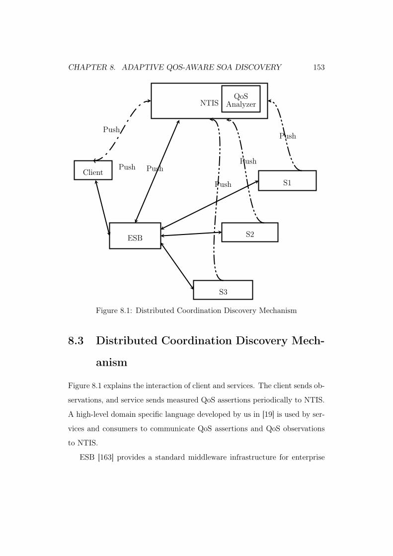
CHAPTER 8. ADAPTIVE QOS-AWARE SOA DISCOVERY 153
Client
ESB
S1
S3
S2
NTISQoS
Analyzer
Push Push
Push
Push
PushPush
Figure 8.1: Distributed Coordination Discovery Mechanism
8.3 Distributed Coordination Discovery Mech-
anism
Figure 8.1 explains the interaction of client and services. The client sends ob-
servations, and service sends measured QoS assertions periodically to NTIS.
A high-level domain specific language developed by us in [19] is used by ser-
vices and consumers to communicate QoS assertions and QoS observations
to NTIS.
ESB [163] provides a standard middleware infrastructure for enterprise
CHAPTER 8. ADAPTIVE QOS-AWARE SOA DISCOVERY 154
SOA systems. However enterprises are heterogeneous with respect to the
SOA deployment. It means, not all applications are service-oriented or use a
common middleware such as Enterprise Service Bus (ESB) for interaction. In
practice, all applications may not be mature enough for managed QoS-aware
discovery approach. In this approach, there is no fixed transport for com-
munication. As shown in Figure 8.1 clients can interact directly with NTIS
or can use SOA middleware (ESB) as a transport mechanism. After the ini-
tial bootstrap, the client will send measured QoS observations based on its
experience of service interaction to NTIS. Services will update NTIS peri-
odically for any changes in QoS capabilities. For consumers leveraging SOA
infrastructure, updated QoS information is sent to by the Enterprise Service
Bus. Any new service added into the system can self-declaratively inform
NTIS about its QoS assertions. Client and services may also communicate
via ESB, and ESB will update NTIS, regarding updated QoS assertion. As
clients and services do not rely on any fixed transport, this approach serves
the current state of heterogeneous SOA deployments in enterprise systems.
The key steps of service interaction with NTIS are as follows:
• Service sends initial QoS declaration assertions to NTIS.
• Service will periodically push assertions to NTIS based on self-evaluation.
• NTIS updates its information about service QoS.
Similarly, client interaction with NTIS takes place in two major ways, as
explained below
• Clients can also send dynamic updated information about QoS request
based on updates it gets from NTIS.

CHAPTER 8. ADAPTIVE QOS-AWARE SOA DISCOVERY 155
• Clients will refresh its cache based on the response from NTIS and
can send updated QoS request to interact with the service in changing
dynamic conditions.
The key extensions in NTIS to support this approach are as follows:
• Computes and processes declarative QoS assertions and observations,
send to it by distributed service providers and consumers.
• Analyses client QoS Goals.
• Determines service ranking and path to the best service based on the
QoS constraints.
A QoS classification model (QCM) is used for consistent evaluation of
QoS parameters based on its measurable characteristics and topological de-
pendence. Leveraging topological information at an application level helps
in taking care of user-defined and application-defined QoS-aware discovery
mechanism on the enterprise network. A QoS evaluation mechanism (QEM),
is developed based on QCM, to consistently calculate QoS values of all ser-
vice nodes in the system. The next section details the Quality Classification
Model (QCM) and its characteristics .
8.4 Quality Classification Model
Figure 8.2 depicts the Quality Classification model(QCM) conceived in this
study for categorizing QoS attributes. There are two levels of categorization.
The first level marks attributes based on their measurable characteristics as
Measurable vs. Non-Measurable, defined as follows:

CHAPTER 8. ADAPTIVE QOS-AWARE SOA DISCOVERY 156
• [Measurable:] Measurable attributes can be assigned discrete nu-
merical values. For example, Availability or Response Time can be
assigned a numerical value. Such attributes can be defined using three
major characteristics: name, unit, range and values.
• [Non-measurable:] Non-measurable attributes cannot be numeri-
cally measured but can be verified and asserted by the system. These
attributes can be assigned Boolean values of true or false. For exam-
ple, if a server asserts that it supports SSL as a security protocol, a
numerical value cannot be associated with this assertion. It can only be
assigned a Boolean value, and the system can only verify the claim and
return a Boolean value accordingly. These attributes can be defined
using three major characteristics: name, description, unit and value.
Unit in this case is Boolean and value can be “true or false”.
Measurable and Non-measurable attributes and their characteristics are de-
fined using the QoS concept element of QoS DSL defined in [19]. Measurable
QoS attributes are further classified at the second-level into Topologically
Dependent (TD) and Topologically Independent(TI), as defined below:
• [Topologically Dependent:] Measurable attributes that are im-
pacted by the relative location of the client and server in a network
topology are termed “Topologically Dependent (TD)” attributes. For
example, the Response Time of a server is dependent on the relative
location of client. For a set of redundant services, a service that is
topologically nearer will yield a shorter round-trip time (RTT).
• [Topologically Independent (TI):] Measurable attributes that are
independent of client and server are termed “Topologically Independent
(TI)” attributes but are more dependent on individual server capacity.

CHAPTER 8. ADAPTIVE QOS-AWARE SOA DISCOVERY 157
For example, the availability of a server is dependent on deployment
server characteristics and should not vary with the relative location of
consumers interacting with it.
QualityClassification
Model
Measurable
Topologydepen-dent
Topologyinde-
pendent
Non Mea-surable
Figure 8.2: Quality Classification Model
QoS assertions and observations provided during bootstrap will evolve
and change for a running system. A dynamic QoS evaluation mechanism is
developed to evaluate these QoS attributes using QCM. To evaluate these
QoS characteristics, it is required to use a network model to uniquely repre-
sent the nodes in the system and its participating entities. The next section
explains the network model depicted for client-server interaction as a part of
this study.
8.5 Network Model
NTIS already has a topological representation of the network. The foremost
requirement of computation, is for each client using one of the known servers,
to periodically send its measurements of server QoS attributes to NTIS. We
envision that this activity should happen once every 5 minutes. Figure 8.3

CHAPTER 8. ADAPTIVE QOS-AWARE SOA DISCOVERY 158
Node 1C11
Node 2C12
Node 3
Node 4S11
Node 5S12
Node 6S13
Node j
DC1
DC1
DC1
DC1DC2
DC3DCn
Figure 8.3: Network Model
shows the network model used in this study to model client-server behavior
for QoS evaluation.
There are multiple nodes in the system. These nodes are distributed
across data centers in an enterprise. Figure 8.3 shows multiple copies of ser-
vice interface 1 deployed across data centers. S11 indicates the first instance
of service interface 1 at Node 4 in data center 1( DC1). S12 indicates the
second instance of service interface 1 at Node 5 in data center 2 (DC2). Sim-
ilarly S13 indicates the third instance of service interface1 deployed at Node
6 in network at data center 3 (DC3). C11 indicates the first client interacting
with service interface 1 at Node 1 in data center 1 (DC1). C12 indicates the
second client interacting with service interface 1 acting from Node 2 in data
center 1( DC1). These clients can be local to the deployed service interface.
With this depiction of the network model, we identify each service inter-
face uniquely in the system. Each client in the system is identified based
on the service interface it is interacting with. Let each interface or service
CHAPTER 8. ADAPTIVE QOS-AWARE SOA DISCOVERY 159
functionality be represented by index “i” and each instance of the specified
interface be identified by unique index “j”. As a result, Sij represents the jth
server serving the ith interface. Similarly, Cik defines the kth client needing to
interact with the ith interface. It can connect with one of Si’s servers based
on ranking results.
The feedback provided by each client is represented in a quality matrix
of size m*n. In this matrix, a row represents unique deployment of a service
interface identified by “i”, and a column represents a quality attribute iden-
tified by “l”. Let “n” be the total number of quality attributes. For client “k”
interacting with Sij the quality matrix will be as shown in Equation 8.1.
Qjil(k) =
0, row 6= j
qlik, row = j & col = l
(8.1)
qlik measure of lth attribute for kth client
One can see Qilj(k) represents the observations of the kth client for the
ith service interface. We represent Qilj(k) by the short hand notation Q(i,k)
because the other variables are implicit. It is a sparse matrix with only
one row per jth server it is interacting with. During service composition in
an orchestrated environment, one client can interact with multiple service
interfaces, resulting in multiple matrices per server interface.
For client C11 in Figure8.3 interacting with S12, the quality matrix will

CHAPTER 8. ADAPTIVE QOS-AWARE SOA DISCOVERY 160
be as shown in Equation 8.2.
Q(1, 1) =
1 2 3 .... lthcolumn .... nlthcolumn
0 0 0 ...... lth0 .... ....
95 1 80 ...... lthmeasure .... ....
(8.2)
All these observations are sent by each client to NTIS. The next section
details the Quality Evaluation Mechanism of quality attributes based on
Q(i,k).
8.6 QoS Evaluation Mechanism
NTIS has current QoS measurements of all the clients interacting with the
service interface captured using Q(i,k). It also has server QoS measurements
communicated to it during boot strap for that specific interface. With this
data set from the client and server for QoS observations, NTIS processes and
evaluates QoS attributes using the QoS evaluation mechanism. As the client
is the first-hand user of the system, we have devised an evaluation mechanism
of these redundantly deployed services based on its actual invocation feedback
of QoS values. But it differs based on their classification category determined
by QCM. The next section explains the evaluation mechanism of these non-
measurable QoS attributes.
8.6.1 Evaluation of Non-Measurable attribute
Each of the non-measurable(NM) attribute is assigned a Boolean value of true
or false (0/1). Initially, a default value of “false” is assigned to all Boolean
attributes. Let us consider we need to determine the value of the nth NM
attribute. We introduce a Reduction Matrix as shown in Equation 8.3 to

CHAPTER 8. ADAPTIVE QOS-AWARE SOA DISCOVERY 161
filter out the nth measure of quality vector.
Rn =
0, l 6= n
1, l = n
(8.3)
The Reduction Matrix in Equation 8.3 represents a row vector of size “n’
whose value is 0 for all quality attributes except the nth attribute, whose
value needs to be determined.
In principle, we argue that we can obtain the nth NM attribute by the
Hadamard Product [164], using element-wise multiplication of individual
measures of server ‘j’ with the Reduction Matrix. Equation 8.4 represents
qn as the value of nth NM attribute for a server j. Here, the operator ‘o’
represents a Hadamard Product representing element-wise multiplication of
the corresponding vectors. Qa,b and Qa,c represent the quality vector data
set of clients b and c calculated using Equation 8.1.
RnT represents the transpose of the Reduction matrix shown in Equation
8.3. Multiplying the Hadamard product of the whole quality matrices with
RnT results in a Boolean value of 0 or 1 for the nth NM attribute.
qn = RTn ×
∑j
(Q(a, b)oQ(a, c)
) ij (8.4)
For the topology in Figure 8.3, we demonstrate the calculation of SSL
as a NM attribute at server 1 for 1st instance of service (S11). Say SSL
is represented by the 4th index of the Quality matrix. Consider that there
are 4 quality attributes measured for each server: Response Time (RT),
Transaction time (TT), SSL Security (SSL) and Availability (Al). Sample
values of the Quality matrix for server 1 for client 1 are indicated as Q(1,1)
CHAPTER 8. ADAPTIVE QOS-AWARE SOA DISCOVERY 162
as shown in Equation 8.5 .
Q(1, 1)1 =
RT TT SSL AL
1 2 1 90
0 0 0 0
(8.5)
The value of SSL will be calculated, using Equation 8.6:
q4 = RT4 ∗(Q(1, 1)1oQ(1, 2)1)11 =
[0 0 1 0
]T∗([1 2 1 90]o[2 5 1 95]) = [1]
(8.6)
The calculated value indicates that SSL is 1, i.e., SSL is “true” for server
1. The next section explains the evaluation mechanism for Measurable At-
tributes
8.6.2 Determination of Measurable attributes
Discrete measurable quality attributes must be handled in a different manner,
as categorized by QCM classification. These quality attributes can be further
classified into topologically dependent or independent, as shown in Figure 8.2.
We first detail the evaluation methodology of TD attributes.These attributes
use Dijkstra algorithm to determine network cost based on distance.
Evaluation of Topologically Dependent Measurable Attributes
To measure the value of Topologically Dependent (TD) attributes, it is im-
portant to understand and define their relationship with topology. The un-
derlying mechanism of collaborating feedback is same. We propose a mecha-
nism to calculate values of TD attributes at a specific server by considering
the statistical aggregation of network distance (ND) as determined by Algo-
rithm 1.

CHAPTER 8. ADAPTIVE QOS-AWARE SOA DISCOVERY 163
Algorithm 1: Determination of TD Measurable attributesData: rmk: current response time of server with interface m at location k;Rmk: a set with new observations of Response Time with m at location k;ndij: denote the network distance from node i to node j considering there is adirect edge from i to j;Ob: defines all set of observations for TD attributes in previous cycle;Obm: current set of observations for TD attributes grouped by interface m;NDij : observation of distance from node i to j;Result: Network distance matrix/* 1 */forall Obm ∈ Ob do
Let Smk be the set of observations for server k for interface m;/* 2 */forall Smk ∈ Obm do
Let Cmkr be an element of Smk if |Smk| =1 thenfor i = ktor do
ndij+ = ndij;endRmk = Cmkr -ndij;
end/* calculate the minimum value from the set Smk and assign it
Cmk */else
Cminmkr=min(Smk);
foreach Cmkr ∈ Smk doif Cmkris firstelement then
rtmk =Cmkr-ndij ;endelse
NT=Cmkr-rtmk;end/* Find path from k to r */foreach edge e from y to z do
eyz = NT ∗ ndyz/∑
ndij ;NDyz=NDyz +eyz;
endend
endend
endforeach NDij do
NDij += NDij ;if |(NDij)| < 5 then
ndij=Mean(NDij);endelse
ndij=Median(NDij);end
end
CHAPTER 8. ADAPTIVE QOS-AWARE SOA DISCOVERY 164
To explain the algorithm, let us measure the TD attribute Response Time
(RT). Response Time can be defined as a sum of “Network Transmission time”
(NTT) and “ Server processing time” (SPT), as shown in Equation 8.7.
Responsetime = SPT +NTT (8.7)
SPT is independent of topology. It is more dependent on server char-
acteristics. In contrast, NPT is dependent on relative network topological
distance of the client from the server. The measure of response time sent by
the client cannot be simply used to determine the root cause of the delay.To
solve this puzzle, we made certain simple assumptions as listed below:
• Server Processing Time (SPT) is defined to be the least time re-
ported by any client interacting with that service in that “Reporting
Cycle”.
• Reporting cycle is defined as the time in which we record responses
from all clients and process them in a single batch. It can be in the
range of 15 to 30 min based on the scenario.
Next we explain the stepwise execution sequence of Algorithm 1 to calculate
response time. Let the network delay from node i to j be denoted by NDij
and let NDSij denote the set with current observation for edge “ij”. Let Smk
be defined as the current observations of server k for interface m. The steps
of execution of the algorithm are as follows:
• [Step1:] As a first step, group all the observations of the last cycle
QoS data-set by server interface.
• [Step2:] Repeat Step 2 to Step 7 for all known service interfaces when
current is j.
CHAPTER 8. ADAPTIVE QOS-AWARE SOA DISCOVERY 165
• [Step 3]: For jth interface repeat Step 3 to Step7.
• [Step4:] For Smk, obtain all the client observations and repeat Step 4
to Step7.
• [Step5:] If there is only one observation for Smk ‘Use the current values
of ND ij to determine server time’ else ‘Use the lowest Response Time
measure as a Server Response Time of Smk and proportionally distribute
remaining time along the path from Ckm to Sij’.
• [Step6:] For each NDij, if the number of elements in the set is less
than or equal to“5” “ndij = Mean(NDSij) ” else “ndij = Median(NDSij)
”
• [Step7:] If new value of NDij is within the tolerance level for all values,
double the reporting cycle capping it at once an hour. If the value of
NDij is more than 5 times the tolerance level for any value, reduce the
repeat cycle time.
To further explain we begin by choosing a minimum value of an attribute
from the QoS measurements data set as a base value. The current value is
determined based by proportionally distributing the next minimum value of
the data set along the path from source to destination. This path can also
be weighted. Finally, statistical measurements are used to determine the
weighted average value.
Topologically independent (TI) attributes are not impacted by the relative
topological location of client and server. Hence, these attributes can be
determined at a specific server node independent of client location. The next
section explains the mechanism for evaluating these attributes.

CHAPTER 8. ADAPTIVE QOS-AWARE SOA DISCOVERY 166
Evaluation of Topologically Independent Attributes
These attributes do not depend on the location of client and server. We em-
ployed a similar statistical algorithm to evaluate them. The process consists
of taking the median of all the observations in the previous reporting cycle
for the specified server, which works perfectly because the median value de-
fines the half-way mark in terms of agreement among all clients of the service
which can act as a good measure of the behavior of the service.
So far, we have described a mechanism to define and measure QoS attributes
in a distributed environment. The next section explains the Service Selection
Algorithm implemented in NTIS to discover services adaptively based on the
dynamic QoS requirements of consumers.
8.7 Service Selection Algorithm
The QoS selection process requires clients to specify criteria on which to se-
lect a service endpoint. QoS DSL[19], is used as a language for specifying
QoS constraints to the NTIS server. QoS measurements are centralized in
the NTIS server, which further uses them for service selection. A client re-
quest specifies conditions by which to choose the service. NTIS acts as a
service selection engine to select service based on selection criteria provided
in client request. Clients can specify two types of conditions, Boolean and
minimization, to specify QoS constraints also known as QoS Goals. Boolean
constraints express client requirements using Boolean constraints like ‘Avail-
ability should be greater than 0.95’. Minimization constraints express mini-
mization conditions such as ‘Minimum Response Time’ or ‘Minimum Cost’.
These constraints need to be analyzed for service selection. Based on the
type of constraints, we have different resolution mechanisms to resolve these

CHAPTER 8. ADAPTIVE QOS-AWARE SOA DISCOVERY 167
constraints. Results from both resolution mechanisms are later consolidated
to select the required service.
To resolve QoS constraints, the results obtained from QoS evaluation
mechanism in the previous section are leveraged. As a result of QEM, NTIS
has QoS measurements for all server deployments. Let QMi be the Qual-
ity Matrix for service interface i whose rows represents servers and whose
columns represent quality attributes. We will leverage QMi to resolve client
constraints based on the service interface required by the client. The next
section explains the resolution mechanism for Boolean client constraints.
8.7.1 Resolution of Boolean Client Constraints
We define two terms to evaluate Boolean Client Constraints, the Boolean
Reduction Factor (BRF) and Boolean Condition Vectors (BCV) as defined
below.
• [Boolean Condition Vector (BCV):] The BCV of a quality at-
tribute is a column vector obtained by the evaluation of Boolean con-
ditions on the lth attribute column of QMik for client k.
• [Boolean Reduction Factor (BRF):] BRF is a reduction function
obtained by boolean ”AND” of all the Boolean Condition Vectors. Per-
forming Boolean ”AND” of all the Boolean Conditions Vectors results
in a single vector representing all the Boolean conditions.
Once Boolean conditions are evaluated, all these BCV’s are evaluated to
yield BRF. BRF is a reduction function that is obtained by boolean ”AND”
of all BCV as defined in Equation 8.8. Equation 8.8 represents ”Boolean

CHAPTER 8. ADAPTIVE QOS-AWARE SOA DISCOVERY 168
AND” of n BCV’s for the ith server interface as requested by client k
BRFk =n∏
i=1
BCVi (8.8)
For client k needing to interact with service interface i, QMik represents the
QMi vector it will act upon. Boolean conditions specified by the client are
picked up one by one to create the Bik vector. Each Bi
k vector results from
the evaluation of the Boolean condition on the ith column of QMik.
Hence, each individual BCV represents the set of servers satisfying partic-
ular Boolean conditions for that interface. The Boolean Reduction Function
reduces the Boolean constraints to a single vector representing servers ca-
pable of satisfying the client conditions. The next section demonstrates the
resolution mechanism for minimization conditions in client QoS constraints.
8.7.2 Minimization of Discrete conditions
The final phase of the selection process is the minimization of discrete con-
ditions. The BRF derived in the previous section also participates in this
process. Discrete conditions can be defined as being topologically aware or
unaware based on the attributes they are defined for. For TD attributes such
as Response Time, we derive Network Cost (NC) based on Network Distance
(ND) derived in Algorithm 1. ND captures the cost of traversal in network
topology. We ran the Dijkstra algorithm to obtain NC from ND.
The next stage consists of resolving the QoS constraints together. All Boolean
conditions are reduced to a single BRF vector, and all discrete conditions are
either dependent on the NC matrix or have a discrete vector for TI attributes
as Cost.
Say there is an operation cost associated with each server in the network.

CHAPTER 8. ADAPTIVE QOS-AWARE SOA DISCOVERY 169
Let Cn represent the operation cost for the server located at nth node in
topology. This value is a standard cost for interacting with that server for
any specific operation and is a TI attribute.
On the other hand, TD cost is obtained by reducing the network cost
matrix based on client location. A Reduction Vector as defined in Equation
8.9 is used to determine network cost(NC).
R(j)k = 1 forj = k
= 0 otherwise(8.9)
The Network Cost(NC) for the client running at node k is then calculated
by reducing NC as shown in Equation 8.10
NCk = NC ∗Rk (8.10)
8.7.3 Optimization Approach
Once network cost and BRF is calculated, we need to minimize the combined
cost. An optimization approach is then used to discover the services based on
the minimized cost. The next step involves the Hadamard product of Ck and
NCk respectively, with the BRF(k) vector resulting in two feature vectors,
the Topologically Independent Feature Vector(TIFV) and the Topologically
Dependent Feature Vector(TDFV). This step ensures the removal of nodes
that do not satisfy Boolean constraints. We define two costs as listed below,
for TI and TD attributes .
• Topologically Independent Feature Vector (TIFV): This vector filters
out servers satisfying BRF for topologically independent costs in the
network. It is calculated as a Hadamard Product of the TI cost vector

CHAPTER 8. ADAPTIVE QOS-AWARE SOA DISCOVERY 170
and the Transpose of BRF. For Cn it is calculated as shown in Equation
8.11.
TIFVk = CnoBRFTk
(8.11)
• Topologically Dependent Feature Vector (TDFV): This vector captures
servers satisfying BRF for topologically dependent costs in the network.
This cost is determined using Network Cost for that specific client.
It is obtained by Hadamard Product of NCk with BRF, as shown in
Equation 8.12.
TDFVk = NCkoBRFk (8.12)
Finally, we define a minimization function using linear regression to yield
the lowest value as the normalized sum of both feature vectors. Equation
8.13 and 8.14 calculate the normalized values of TIFV and TDFV.
FC(k) = norm(TIFVk) (8.13)
FNC(k) = norm(TDFVk) (8.14)
Equation 8.15 shows the optimization function obtained by element wise
multiplication of Equation 8.13 and 8.14.
J(k) =
FC(k) ∗ FNC(k), if FC(k) > 0 FNC(k) > 0
MaxInteger, otherwise
(8.15)
Based on the equation 8.15, it is clear that it is not strictly convex. The
fact that we have Maxinteger across the equation make it difficult to create a
convex optimization [165] for linear regression. A straight forward approach
to solve this problem would be to iterate through all the elements in J(k).

CHAPTER 8. ADAPTIVE QOS-AWARE SOA DISCOVERY 171
We present an optimization that would reduce the problem space drastically.
It uses the fact that global optimum is not present at a point, where the
value of J(k) is MaxInteger. Hence we should not iterate over the elements
which represent MaxInteger. Also it can be argued that MaxInteger represent
points, which do not satisfy the constraints for the QoS Goals.
As a result of the above argument, we use the BRF matrix to find set
of elements that need to participate in global optima selection. This process
helps to drastically reduce the problem space to the candidate services that
satisfies discrete function requirements. The optimization approach has been
fully explained in section 8.8.2 with example and data-points.
The next section provides a motivating example of a distributed enterprise
using this mechanism to discover redundant services based on client QoS
requirements.
8.8 A Motivating Example
Consider an example of a typical enterprise having four data centers located
in New York (NYC), London(LND), Singapore(SNG), and San Jose (SJC).
Nodes in each of these data centers NYC, LND, SNG and SJC host a re-
dundant service represented by a single service interface. We identify it as
service interface 1.
Figure 8.4 shows the topology of this typical enterprise employed for the
execution. Consistently with the terminology adopted, S11, S12, S13 and
S14 represent four redundant services with a common interface 1. Each of
the services S11, S12, S13 and S14 is an inventory service. Clients C1 to C4
for these services are located across all these data centers. As every client
is interacting with service interface 1, we have removed the subscript 1 from
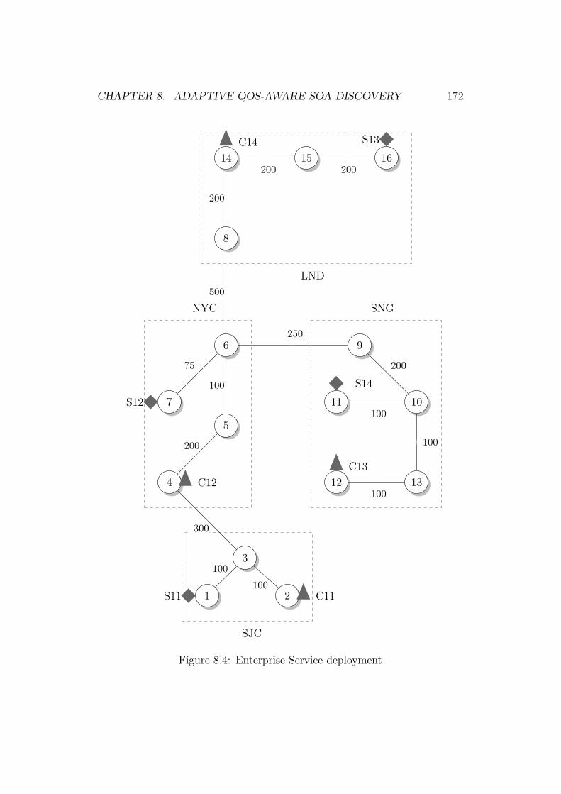
CHAPTER 8. ADAPTIVE QOS-AWARE SOA DISCOVERY 172
SJC
NYC SNG
LND
1 2
3
4
5
6
7
8
9
1011
1312
14 15 16
100
100
300
200
100
75
250
200
100
100
100
500
200
200 200
C11
C12C13
C14
S11
S12
S13
S14
Figure 8.4: Enterprise Service deployment

CHAPTER 8. ADAPTIVE QOS-AWARE SOA DISCOVERY 173
the client identification. Based on our earlier discussion, C2 represents the
second client interacting with service interface 1, and further clients are des-
ignated likewise. The specifications of the network model, of this enterprise
explaining individual client and service deployment in each of these data
centers are explained below.
1. S11 is the first implementation of service interface 1, deployed in the
SJC data center.
2. S12 is the second implementation of service interface 1, deployed in the
NYC data center.
3. S13 is the third implementation, deployed in the LND data center.
4. S14 is the fourth implementation of service interface 1, deployed in
SNG data center.
5. Client C1 is located in the SJC data center.
6. Client C2 is located in the NYC data center.
7. Client C3 is located in the SNG data center.
8. Client C4 is located in the LND data center.
Server CostS11 500S12 600S13 400S14 300
Table 8.1: Cost per Operation for each Server
There is a cost associated with any operation using these server nodes
in different data centers. The cost for the various servers is explained in

CHAPTER 8. ADAPTIVE QOS-AWARE SOA DISCOVERY 174
Listing 8.1: Execution Run
E1 Kill S11 inventory service in SJC
T1 Wait for 2 hrs
E2 Kill S13 inventory service in LND
T2 Wait for 3 hrs
E3 Start service S11 in SJC
T3 Wait for 5 hrs
E4 Kill server S14 in SNG
T4 Wait for 5 hrs
E5 Kill server S12 in NYC
T5 Wait for 5 hrs
E6 Start inventory service S13 in LND
T6 Wait for 6 hrs
E7 Start server S12 in NYC
T7 Wait for 3 hrs
E8 Start server S14 in SNG
Table 8.1.There is also a server processing time of 100 ms for each server.
Clients in each of these data centers will connect to servers within or outside
their respective data centers based on their QoS requirements. The system
is made to run for 5 hrs initially using this algorithm to attain a state of
network equilibrium.
To study the behavior of the system, we inundated a sequence of time
series and event series in the system, as shown in Listing 8.1. Time series [T]
indicates the time for which the state of system remains the same before the

CHAPTER 8. ADAPTIVE QOS-AWARE SOA DISCOVERY 175
next event is triggered. Event series [E] indicates the specific event triggered.
We studied the behavior of all the four clients for different QosGoals. The
next section details and analyses the results of the system behavior for the
minimized Round Trip Time (RTT) as Qos constraint.
8.8.1 Round Trip Time as Qos Goals
In the first example, we define the QoS Goal as minimum RTT (Equation
8.16). Round Trip time is the time delay incurred by the client in the request-
response cycle. It is a topologically dependent attribute and is impacted by
the topological distance between client and service.
QosGoals = Minimum RTT (8.16)
We now try to run the service selection algorithm for client 1. In the
QoS Goal, we don’t have any topologically independent factor. Hence there
is a need to look at the Topologically dependent feature vector (TDFV) in
this case. The equation 8.17 defines the TDFV for the first client (k=1).
The corresponding normalized values, FNC(1) are defined in equation 8.18.
Based on the equation 8.15, J(1) will result as shown in equation 8.19. On
running the service selection algorithm, we would get S11 as the server for
C1. The values of feature vector, cost function and minimization function
will be as follows:
TDFV1 =
250.0
825.0
1850.0
1300.0
(8.17)

CHAPTER 8. ADAPTIVE QOS-AWARE SOA DISCOVERY 176
E 1 E 2 E 3 E 4 E 5 E 6 E 7 E 8
E 1 E 2 E 3 E 4 E 5 E 6 E 7 E 8
E 1 E 2 E 3 E 4 E 5 E 6 E 7 E 8
E 1 E 2 E 3 E 4 E 5 E 6 E 7 E 8
10500
11000
11500
12000
12500
13000
10500
11000
11500
12000
12500
13000
10500
11000
11500
12000
12500
13000
10500
11000
11500
12000
12500
13000
12
34
0 10 20 30 40Time
TotalR
ound
Trip
Tim
e
client1234
Figure 8.5: Client Rtt plots for minimum RTT
FNC(1) =
5.92
19.53
43.79
30.77
(8.18)
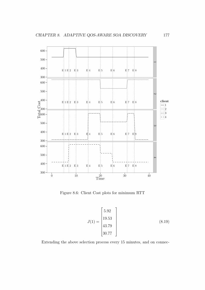
CHAPTER 8. ADAPTIVE QOS-AWARE SOA DISCOVERY 177
E 1 E 2 E 3 E 4 E 5 E 6 E 7 E 8
E 1 E 2 E 3 E 4 E 5 E 6 E 7 E 8
E 1 E 2 E 3 E 4 E 5 E 6 E 7 E 8
E 1 E 2 E 3 E 4 E 5 E 6 E 7 E 8
300
400
500
600
300
400
500
600
300
400
500
600
300
400
500
600
12
34
0 10 20 30 40Time
TotalC
ost client
1234
Figure 8.6: Client Cost plots for minimum RTT
J(1) =
5.92
19.53
43.79
30.77
(8.19)
Extending the above selection process every 15 minutes, and on connec-
CHAPTER 8. ADAPTIVE QOS-AWARE SOA DISCOVERY 178
tivity failure to server, we plotted the time series graph for client round trip
and cost for events run in Listing 8.1. Cost is determined by the server the
client is connecting with at any point in time. The time series graphs in
Figure 8.5 show the behavior of client round trip time. The corresponding
transition in client behavior for the cost is shown in Figure 8.6.
Let us now try to understand the events impact on the minimization. We
start the discussion with Client 1 and Rtt graph in Figure 8.5. It indicates
that upon event E1, when server S11 goes down in SJC, C1 starts interacting
with S12 in NYC, which is next in ranking for the least topological distance.
On E3, when SJ comes up, C1 resumes interacting with S11 in SJC because
it is local and offers the least topological distance. The remaining events
have no impact on C1 due to topological distance. For client C1 in Figure
8.6, the cost of the server changes from 500 cents to 600 cents and back,
depending on the cost of the server it is connecting with, that is S11 and S12
respectively.
In case of Client 2, it is impacted by the event E5. Upon E5, when S12
goes down, C2 starts interacting with S11 in SJC because it provides the
same RTT, resulting in a near constant line. But at the same if we look at
cost(Figure 8.6), we would see a drastic reduction in the cost since S11 has
lower cost. Notice that since the minimization function is dependent on RTT
and not Cost, client first connects to S12 even when S11 shows lower Cost.
Client C3 is by default connecting to the server S14 for minimum RTT.
Figure 8.5 indicates that upon E4, when S14 goes down, the client transitions
to S12 in NYC. When S12 goes down after 3hrs(E5), C3 starts connecting
to the server S11 in SJC, reconnects to S12 on E7, and returns to S14 upon
E8. The corresponding change in cost is shown in Figure8.6.
Figure 8.5 indicates that when server S13 goes down at E2, C4 connects

CHAPTER 8. ADAPTIVE QOS-AWARE SOA DISCOVERY 179
with S12 in NYC. Upon E5, when S12 goes down, C4 connects with S11 in
SJC, as it is the next available server, and reconnects with S12 at E7.
We demonstrated, that once the system attains a state of equilibrium, it
adaptively manages any service failure by re-connecting to another service in
ranking. The next section demonstrates and analyzes the system adaptation
and discovery approach for SSL as a client’s requirement, in addition to
minimum RTT.
8.8.2 SSL and minimum RTT as client QoS Goals
QosGoals =Minimum RTTAnd
SSL Present
where SSL is boolean function
(8.20)
This section analyzes the behavior of the system for client QoS require-
ments of SSL as a security protocol and minimum RTT (Equation 8.20).
SSL is a non-measurable Boolean attribute. The minimization Function in
this case is determined by using the Boolean Reduction Factor to eliminate
services not providing SSL. The remaining services are then ranked for mini-
mum RTT. In our current example, SSL is not supported by S13. As a result,
S13 would be removed by BRF matrix.
In this case, let us first try to study selection algorithm for C1. Since
RTT is Topologically dependent Attribute, the TDFV function is defined in
Equation 8.21. Notice the third row is 0, this is due to BRF matrix and SSL
is false for S13. The corresponding normalized values are defined in Equation
8.22. Since this Qos Goal has no topologically independent attributes, we
would ignore FC(k) as defined in equation 8.13. The final J(1) for the same
is defined in Equation 8.23. The Figure 8.7 tries to plot the function J(1).

CHAPTER 8. ADAPTIVE QOS-AWARE SOA DISCOVERY 180
This plot proves the nonconvex nature of the function J(1).
TDFV1 =
250.0
825.0
0
1300.0
(8.21)
FNC(1) =
10.53
34.74
0
54.74
(8.22)
J(1) =
10.53
34.74
MAXINT
54.74
(8.23)
Further the same selection algorithm is repeated for sequence of events
as shown in Listing 8.1.This impacts the client 4, which connects to S13
in the previous example. Figure 8.8 shows client C4 connecting to S12 for
minimum RTT . Upon E5 when S12 dies, it connects to S11 in SJC, resulting
in a higher RTT.
The corresponding cost graph can be seen in Figure 8.9. The initial
connecting cost for client C6 is 600 cents, which is the cost for server S12 in
NYC, followed by connection to S11, resulting in a cost of 500 cents. In this
case, we see the impact of non-measurable attributes on service selection and
corresponding system behavior. The next section discusses client behavior
for another minimization Functions, defined as a product of RTT and cost.
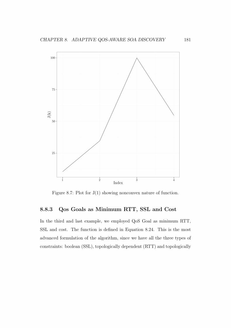
CHAPTER 8. ADAPTIVE QOS-AWARE SOA DISCOVERY 181
25
50
75
100
1 2 3 4Index
J(k)
Figure 8.7: Plot for J(1) showing nonconvex nature of function.
8.8.3 Qos Goals as Minimum RTT, SSL and Cost
In the third and last example, we employed QoS Goal as minimum RTT,
SSL and cost. The function is defined in Equation 8.24. This is the most
advanced formulation of the algorithm, since we have all the three types of
constraints: boolean (SSL), topologically dependent (RTT) and topologically

CHAPTER 8. ADAPTIVE QOS-AWARE SOA DISCOVERY 182
E 1 E 2 E 3 E 4 E 5 E 6 E 7 E 8
10500
11000
11500
12000
12500
13000
4
0 10 20 30 40Time
TotalR
ound
Trip
Tim
e
Figure 8.8: Client Rtt plots for minimum RTT with SSL
E 1 E 2 E 3 E 4 E 5 E 6 E 7 E 8
300
400
500
600
4
TotalC
ost
Time
Figure 8.9: Client Cost plots for minimum RTT with SSL
independent(Cost).
QosGoals =Minimize RTTAnd
Minimize Server Operation CostAnd
SSL Present
(8.24)
To run the selection algorithm for C1, we need to recall that S13 is with-
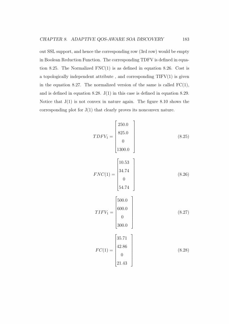
CHAPTER 8. ADAPTIVE QOS-AWARE SOA DISCOVERY 183
out SSL support, and hence the corresponding row (3rd row) would be empty
in Boolean Reduction Function. The corresponding TDFV is defined in equa-
tion 8.25. The Normalized FNC(1) is as defined in equation 8.26. Cost is
a topologically independent attribute , and corresponding TIFV(1) is given
in the equation 8.27. The normalized version of the same is called FC(1),
and is defined in equation 8.28. J(1) in this case is defined in equation 8.29.
Notice that J(1) is not convex in nature again. The figure 8.10 shows the
corresponding plot for J(1) that clearly proves its nonconvex nature.
TDFV1 =
250.0
825.0
0
1300.0
(8.25)
FNC(1) =
10.53
34.74
0
54.74
(8.26)
TIFV1 =
500.0
600.0
0
300.0
(8.27)
FC(1) =
35.71
42.86
0
21.43
(8.28)
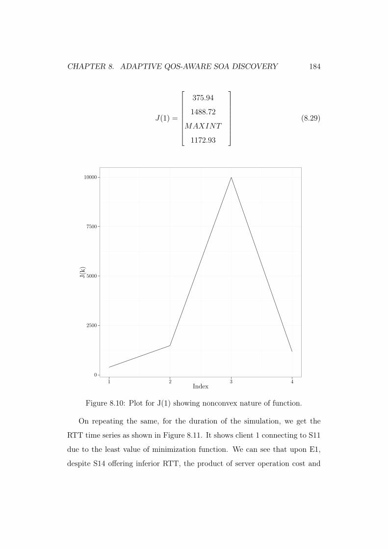
CHAPTER 8. ADAPTIVE QOS-AWARE SOA DISCOVERY 184
J(1) =
375.94
1488.72
MAXINT
1172.93
(8.29)
0
2500
5000
7500
10000
1 2 3 4Index
J(k)
Figure 8.10: Plot for J(1) showing nonconvex nature of function.
On repeating the same, for the duration of the simulation, we get the
RTT time series as shown in Figure 8.11. It shows client 1 connecting to S11
due to the least value of minimization function. We can see that upon E1,
despite S14 offering inferior RTT, the product of server operation cost and

CHAPTER 8. ADAPTIVE QOS-AWARE SOA DISCOVERY 185
E 1 E 2 E 3 E 4 E 5 E 6 E 7 E 8
E 1 E 2 E 3 E 4 E 5 E 6 E 7 E 8
E 1 E 2 E 3 E 4 E 5 E 6 E 7 E 8
E 1 E 2 E 3 E 4 E 5 E 6 E 7 E 8
10500
11000
11500
12000
12500
13000
10500
11000
11500
12000
12500
13000
10500
11000
11500
12000
12500
13000
10500
11000
11500
12000
12500
13000
12
34
0 10 20 30 40Time
TotalR
ound
Trip
Tim
e
client1234
Figure 8.11: Client Rtt plots for QoS Goals as minimum Rtt and Cost
RTT is the least for S14, resulting in C1 connecting to S14. Upon E3, when
S11 resumed operation, C1 connected to it.
The corresponding cost graph in Figure 8.12 indicates the server operation
cost incurred while transitioning to different servers. Figure 8.11 indicates
an initial cost of 500 cents for client C1, which is the operation cost for server
S11, changing to 300 cents upon event E1 when C1 connects instead to S14.

CHAPTER 8. ADAPTIVE QOS-AWARE SOA DISCOVERY 186
E 1 E 2 E 3 E 4 E 5 E 6 E 7 E 8
E 1 E 2 E 3 E 4 E 5 E 6 E 7 E 8
E 1 E 2 E 3 E 4 E 5 E 6 E 7 E 8
E 1 E 2 E 3 E 4 E 5 E 6 E 7 E 8
300
400
500
600
300
400
500
600
300
400
500
600
300
400
500
600
12
34
0 10 20 30 40Time
TotalC
ost client
1234
Figure 8.12: Client Cost plots for minimization function as product of Rttand Cost
We observed that when using the product of RTT and server operation
cost as a minimization function, if the cost per operation is less than RTT,
clients will connect to the server offering the lower cost, and vice versa.
The above three examples in the simulation, clearly shows execution of the
selection algorithm and also impact of the various type of variables: boolean,

CHAPTER 8. ADAPTIVE QOS-AWARE SOA DISCOVERY 187
topologically dependent and topologically independent. In the next section,
we detail at the simulation software that is developed as part of this work.
8.8.4 Simulation Software and Reproducibility
The above algorithm is implemented as simulation software in Scala, and the
same is open sourced at https://github.com/msikri/simulation. The
software is written in Scala and the associated graphs are plotted using R.
The R scripts are also provided in repository. The application was executed
on Ubuntu 14.04, But should in principle work on any Unix. The steps to
reproduce the above simulation are as follows:-
• Setup Scala project.
We have used Scala ide http://scala-ide.org/ for building the sim-
ulator system. But any Scala aware editor would work.
• Modify the experiment for execution.
The experiment or simulation setup is done in Creator2.scala https://
github.com/msikri/simulation/blob/master/expt2/src/main/scala/
org/apache/ntis/sim/base/creator/Creator2.scala. The line no
47-53 defines the QoSGoal for the experiment. Based on the need, we
need to select one of them.
• Running the experiment.
The simulation can be executing by running Exp2App.scala https://
github.com/msikri/simulation/blob/master/expt2/src/main/scala/
org/apache/ntis/sim/base/Exp2App.scala. It results in generation
of metrics.txt file (location user.home/sim/metric.txt). The metrics
CHAPTER 8. ADAPTIVE QOS-AWARE SOA DISCOVERY 188
file contains the cost and Rtt readings as observed on the clients at the
various times during the experiment.
• Data Cleanup.
The data cleanup setup involves taking up metric files and cleaning
it and converting it into csv format for analysis and plotting. The
cleanup operation is carried out by DataClean.scala https://github.
com/msikri/simulation/blob/master/base1/src/main/scala/org/
apache/ntis/sim/data/DataClean.scala . We should execute Dat-
aClean.scala for generation of processed files clientRttall.csv location
(user.home/sim/process/clientRttall.csv) and clientCostall.csv loca-
tion (user.home/sim/process/clientCostall.csv).
• Plotting the Graphs
The data is plotted using Rproject/ggplotscript.R. The script also as-
sumes the location of the files clientRttall.csv and clientRttall.csv as
defined above. It uses the time series data in the csv files and plots the
corresponding time series graphs for cost and Rtt respectively.
All of the above examples, can be recreated using the steps provided
above. For each set of experiment, the Creator2.scala need to be modified
to be re-execute. The Open source software contains a Time Multiplexed
simulator complete written in Scala using Akka based Eventing. The source
code is open sourced for bringing in reproducibility in the data provided.
8.9 Summary
The vision of Adaptive Service Oriented Enterprise (ASOE) requires engrain-
ing the adaptiveness in the core and foundational layers. In case of SOA it

CHAPTER 8. ADAPTIVE QOS-AWARE SOA DISCOVERY 189
starts foundational services layer. Managed redundancy and replication are
required to provide a quality driven controlled environment for enterprise sys-
tems. This chapter explains an adaptive framework and supporting artifacts
developed to enable the same. Distributed Coordination Discovery mecha-
nism (DCDM), Quality Classification Model (QCM) and Quality Evaluation
Mechanism (QEM) are three key contributions of this framework. DCDM
enables distributed interaction of service providers and service consumers
with NTIS to provide real-time feedback of the system. The feedback is used
to evaluate QoS at each node in the system using Quality Evaluation Mech-
anism to attain a state of network equilibrium. Ranking is determined by
NTIS based on QEM and a service selection algorithm allowing considera-
tion of the cost of servers across different data centers. The value of QoS
attributes as observed or asserted by the consumer and provider are pro-
vided as feedback to a centralized broker. In literature there are various
ways to provide feedback [166] like fuzzy logic [64], prediction-based [167],
reputation-based [168], [169]. In our approach QoS values provided by the
clients, are values observed by the actual invocation of the services. The ap-
proach of quality vector aggregation has also been proposed in other works
like [98] and [108]. In[98] QoS data retrieval mechanism differs based on the
QoS dimension of the attributes. The work in [108] calculates aggregated
quality vectors for composite tasks in services based on their relationship in
the workflow. In current approach, these values are regularly provided by
consumers and services themselves using the common QoS domain specific
language[19]. It aids in selecting the best service out of multiple functional
similar services given the client constraints. The solution provided in this
approach is generic enough to cater to different minimization functions and
is not bound to a single objective function as is the requirement. The next

CHAPTER 8. ADAPTIVE QOS-AWARE SOA DISCOVERY 190
chapter concludes the work and future scope.

Chapter 9
Conclusion and Future Work
The major contributions of the thesis are the following:
First a formal methodology is designed that allows agile SOA develop-
ment by providing a prioritized set of functional and non-functional agile
requirements. This methodology is a modified form of Software Quality Func-
tion Deployment technique known as Blitz-QFD. The default methodology
is not SOA specific and does not mandate non-functional requirements. The
modified methodology known as Blitz-CSOA takes care of designing service-
oriented systems with specific consideration of non-functional requirements
allowing prioritization of requirements based on customer needs. The three
key steps added in the methodology are related to adding contextual in-
formation for design requirements, building HOQ matrix for non-functional
requirements and adding decision matrix to align customer needs with the
architect feedback. To suit the differentiated needs of enterprise systems two
new scales (convex and normal), have been developed to rate the require-
ments based on time-to-delivery needs. The methodology has been demon-
strated using a Case Study for B2B e-procurement system.
The second key contribution of this work is an Adaptive QoS-aware dis-
191

CHAPTER 9. CONCLUSION AND FUTURE WORK 192
covery framework for redundant-services, describing Distributed Coordina-
tion Discovery Mechanism (DCDM) developed as part of this work. It ex-
hibits self-healing and self-management capabilities. The self-healing is ex-
hibited by automatic of the system and clients from service failures during
run-time. The self-management capabilities are engrained in the architecture
by enabling service providers and consumers to share there state, capabilities,
goals and feedback during run-time. This mechanism has been developed in
a phased manner. At first an architecture has been proposed that uses Net-
work Topological Information Service (NTIS) as a broker to determine the
ranking of services . This calculates the ranking of services using using Dijk-
stra algorithm and topological metadata information of the service providers
and consumers. As a next step a high-level domain specific language is being
defined in order to enable communication among the participating entities
in the system. It allows defining QoS capabilities and client QoS goals. Web
Service Proximity Resolution Framework(WS-PR) framework is a represen-
tative architecture, that is built to understand the success of using service as
NTIS and topological metadata to determine the ranking of service. It could
only detemine the ranking based on proximity as QoS.
Finally DCDM uses NTIS and DSL, all of them are developed in this work,
to enable adaptive discovery for generic QoS parameters. A QoS classification
mechanism(QCM) is defined to classify quality attributes in the system. A
QoS evaluation approach (QEM) is designed to calculate QoS at each node in
the system leveraging feedback provided by consumers. NTIS determines the
ranking of service using topological metadata, quality evaluation mechanism
and service selection algorithm. A new service selection algorithm has been
designed using global optimization approach to calculate the ranking of the
service based on the minimization function determined by client QoS goals.

CHAPTER 9. CONCLUSION AND FUTURE WORK 193
The service selection algorithm ranks the service. The next section explains
the key scientific contributions of the research work.
9.1 Scientific Contributions
During the tenure of this research papers have been submitted and publica-
tions are made. This section summarizes the individual works in the table
9.1.
The research is divided based on the service development cycle phase it is
targeting. As part of enhancing the requirement phase, we decided to extend
the QFD model for Non-functional agile SOA requirements. The work related
to this was published in International Journal on Collaborative Enterprise
[17] in 2014.
In the design phase we first defined the framework for web service selection
using topological metadata called Web Service Proximity Resolution (WS-
PR). This work is published in ACE 2010 by IEEE [18]. The framework is
written in Java. Post to this work we defined the QoS language [in Groovy],
which can be used to define the constraints and assertions, in the web services
domain. This work is published by Springer [19] in 2011. In the third work
in the series, the foundation is laid by connecting the first two works(NTIS
and QoS), and build the framework for using QOS language in web service
selection framework. The same was published in ICC 2014, that is published
by IEEE [170]. The survey of the existing discovery mechanism is also carried
out to understand the gaps and alignment with enterprise needs. The paper
related to that is submitted in Computer Science Review Journal, Elsevier.
In the development phase, various models and mechanism in which dis-
covery frameworks can be implemented is discussed. This work was published

CHAPTER 9. CONCLUSION AND FUTURE WORK 194
Phase Title Conference or Journal
Requirement Derivation of agile SOArequirements usingcollaborative QFD
International Journal ofCollaborative Enterprise 4(4), 234-248 ,Year 2014
Design
Web Service Selection UsingTopological Metadata
International Conference onAdvances in Computer
Engineering (ACE), Year2010
Design of Domain SpecificLanguage for Web ServicesQoS Constraints Definition
Information Technology andMobile Communication,
411-416 ,Year 2011
Service Discovery for SOASystems with Topological and
QoS Constraints
International Conference onCommunication and
Computing (ICC-2014), 5 ,Year 2014
Survey and Impact ofQoS-aware SOA discoverymechanism in real-worldenterprise environments
Computer Science ReviewJournal, Elsevier (Submitted)
Development
Adaptive SOA stack anddiscovery framework for
redundant services
9th International Conferenceon Industrial and InformationSystems (ICIIS), Year 2014
Adaptive QoS-awarediscovery mechanism forenterprise SOA systems
ACM Journal, Transactionon the web (Submitted)
Table 9.1: Table containing all publication
in ICIIS 2014 [76] by IEEE. And finally, an adaptive QoS-aware discovery
SOA solution is proposed bringing all the components defined above in a sin-
gle system. Then the system is defined and simulated in the Scala language.
All the associated source code is open sourced on GitHub. This final paper
with simulation data and details is submitted in ACM Journal, Transaction

CHAPTER 9. CONCLUSION AND FUTURE WORK 195
of the Web.
Blitz-CSOA is a methodology which adds and modifies steps in Blitz-QFD
to suit adaptive SOA design needs . This methodology has been evaluated
via case study for complex distributed architecture of B2B system. The
Agile requirements yielded as part of this methodology will result in devel-
oping the required foundational services. While designing the system using
these services the adaptive discovery needs are fulfilled by Adaptive discov-
ery framework developed as part of Chapter 8 in the thesis. The framework
ensures that services and consumer communicate with each other using NTIS
and DCDM to yield the benefit of adaptive discovery. The evaluation results
of this framework for generic QoS parameters (like SSL, RTT) have been
discussed in the same chapter.
A simulation software has also been developed to simulate the discovery
for a given network topology. The software is open sourced for sharing and
future research. The results are being shared with a motivating example
indicating the high performance and correct behavior of the system. The
architecture proposed for the framework is highly scalable, self-managing
and self-discovering catering to the plug and play nature of adaptive services
in global enterprise environment. The next section details the scope of future
work.
9.2 Future Work
The above contributions are the key steps in realizing the vision of Adaptive
SOA. It enables measured design and discovery of service oriented enterprise
systems that can scale to Adaptive enterprise needs. The manual or verbal
prioritisation by product managers in Agile development methodology is not
CHAPTER 9. CONCLUSION AND FUTURE WORK 196
a fool-proof solution. Requirement Elicitation is an important activity in
SOA systems to avoid any pervasive impact of recurrring cost of re-design.
Not only that, it is important that prioritized requirements are also served in
each iteration in a manner to yield adaptive design. Being consumer driven,
there is less risk of requirements variability using Blitz-CSOA as it is derived
from top customer needs.
Blitz-CSOA is limited to HOQ as a deployment mechanism for require-
ments elicitation. It would be worthwhile to extend it to consider other
aspects of deployment like Kansei engineering [171] and FMEA [172] for
Blitz-CSOA. The adaptive discovery framework has been demonstrated for
generic QoS use cases. However it would be more beneficial to consider its
applicability for dynamic IoT use cases, where devices may add and leave the
network on the fly. The simulation software, language and the broker ser-
vice implementations are shared for further extension for the SOA research
community.

Appendix A
Webservice Topological Selection
NTIS Details
A.1 Service definition for Services
A.1.1 NTIS Service
1 <?xml version="1.0" encoding="UTF−8" standalone="yes"?>
2 <wsdl:definitions xmlns:soap="http://schemas.xmlsoap.org/wsdl/
soap/" xmlns:tns="http://www.example.org/NTISService/"
xmlns:wsdl="http://schemas.xmlsoap.org/wsdl/" xmlns:xsd="
http://www.w3.org/2001/XMLSchema" name="NTISService"
targetNamespace="http://www.example.org/NTISService/">
3 <wsdl:types>
4 <xsd:schema targetNamespace="http://www.example.org/
NTISService/" xmlns:Q1="http://www.ntis.org/schema">
5 <xsd:import namespace="http://www.ntis.org/schema"
schemaLocation="./NTIS.xsd" id="ntis" />
197

APPENDIX A. WEBSERVICE TOPOLOGICAL SELECTION NTIS DETAILS198
6 <xsd:element name="getProximityList">
7 <xsd:complexType>
8 <xsd:sequence>
9 <xsd:element name="servicelocation" type="tns:
ServiceLocationType" maxOccurs="1" minOccurs="1" />
10 <xsd:element name="clientlocation" type="Q1:LocationType
" maxOccurs="1" minOccurs="1" />
11 </xsd:sequence>
12 </xsd:complexType>
13 </xsd:element>
14 <xsd:element name="getProximityListResponse">
15 <xsd:complexType>
16 <xsd:sequence>
17 <xsd:element name="locationProximityData" type="tns:
locationProximityDataType" />
18 </xsd:sequence>
19 </xsd:complexType>
20 </xsd:element>
21 <xsd:complexType name="ServiceLocationType">
22 <xsd:sequence>
23 <xsd:element name="site" type="Q1:LocationType" />
24 </xsd:sequence>
25 </xsd:complexType>
26 <xsd:complexType name="locationProximityDataType">
27 <xsd:sequence>
28 <xsd:element name="locationProximity" type="Q1:
LocationProximityType" maxOccurs="unbounded"

APPENDIX A. WEBSERVICE TOPOLOGICAL SELECTION NTIS DETAILS199
minOccurs="0" />
29 </xsd:sequence>
30 </xsd:complexType>
31 </xsd:schema>
32 </wsdl:types>
33 <wsdl:message name="getProximityListRequest">
34 <wsdl:part element="tns:getProximityList" name="parameters"
/>
35 </wsdl:message>
36 <wsdl:message name="getProximityListResponse">
37 <wsdl:part element="tns:getProximityListResponse" name="
parameters" />
38 </wsdl:message>
39 <wsdl:portType name="NTISService">
40 <wsdl:operation name="getProximityList">
41 <wsdl:input message="tns:getProximityListRequest" />
42 <wsdl:output message="tns:getProximityListResponse" />
43 </wsdl:operation>
44 </wsdl:portType>
45 <wsdl:binding name="NTISServiceSOAP" type="tns:NTISService
">
46 <soap:binding style="document" transport="http://schemas.
xmlsoap.org/soap/http" />
47 <wsdl:operation name="getProximityList">
48 <soap:operation soapAction="http://www.example.org/
NTISService/getProximityList" />
49 <wsdl:input>

APPENDIX A. WEBSERVICE TOPOLOGICAL SELECTION NTIS DETAILS200
50 <soap:body use="literal" />
51 </wsdl:input>
52 <wsdl:output>
53 <soap:body use="literal" />
54 </wsdl:output>
55 </wsdl:operation>
56 </wsdl:binding>
57 <wsdl:service name="NTISService">
58 <wsdl:port binding="tns:NTISServiceSOAP" name="
NTISServiceSOAP">
59 <soap:address location="http://www.example.org/" />
60 </wsdl:port>
61 </wsdl:service>
62 </wsdl:definitions>
Listing A.1: NTIS service WSDL
1 <?xml version="1.0" encoding="UTF−8"?>
2 <schema xmlns="http://www.w3.org/2001/XMLSchema"
targetNamespace="http://www.ntis.org/schema"
3 xmlns:tns="http://www.ntis.org/schema"
elementFormDefault="qualified">
4
5 <simpleType name="LocationType">
6 <restriction base="string"></restriction>
7 </simpleType>
8 <element name="location" type="tns:LocationType"></
element>

APPENDIX A. WEBSERVICE TOPOLOGICAL SELECTION NTIS DETAILS201
9
10
11 <element name="LocationProximity" type="tns:
LocationProximityType">
12 </element>
13
14 <complexType name="LocationProximityType">
15 <sequence>
16 <element name="location" type="tns:
LocationType" maxOccurs="1"
17 minOccurs="1">
18 </element>
19 <element name="proximity" type="tns:
ProximityType" maxOccurs="1"
20 minOccurs="1"></element>
21 </sequence>
22 </complexType>
23
24 <simpleType name="ProximityType">
25 <restriction base="long"></restriction>
26 </simpleType>
27
28 <complexType name="ServiceLocationType">
29 <sequence>
30 <element name="site" type="tns:
LocationType" maxOccurs="unbounded"
minOccurs="0"></element>
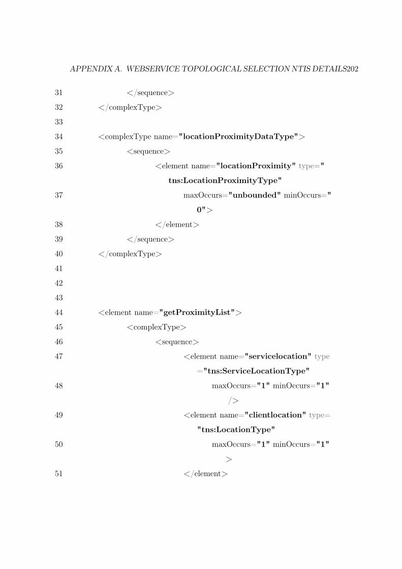
APPENDIX A. WEBSERVICE TOPOLOGICAL SELECTION NTIS DETAILS202
31 </sequence>
32 </complexType>
33
34 <complexType name="locationProximityDataType">
35 <sequence>
36 <element name="locationProximity" type="
tns:LocationProximityType"
37 maxOccurs="unbounded" minOccurs="
0">
38 </element>
39 </sequence>
40 </complexType>
41
42
43
44 <element name="getProximityList">
45 <complexType>
46 <sequence>
47 <element name="servicelocation" type
="tns:ServiceLocationType"
48 maxOccurs="1" minOccurs="1"
/>
49 <element name="clientlocation" type=
"tns:LocationType"
50 maxOccurs="1" minOccurs="1"
>
51 </element>

APPENDIX A. WEBSERVICE TOPOLOGICAL SELECTION NTIS DETAILS203
52 </sequence>
53 </complexType>
54 </element>
55 <element name="getProximityListResponse">
56 <complexType>
57 <sequence>
58 <element name="
locationProximityData" type="
tns:locationProximityDataType"
/>
59 </sequence>
60 </complexType>
61 </element>
62 </schema>
Listing A.2: NTIS service schema refered in WSDL NTIS.xsd
A.1.2 Stock Quote Service
1 <?xml version="1.0" encoding="UTF−8" standalone="yes"?>
2 <wsdl:definitions xmlns:soap="http://schemas.xmlsoap.org/wsdl/
soap/" xmlns:tns="http://www.example.org/NTISService/"
xmlns:wsdl="http://schemas.xmlsoap.org/wsdl/" xmlns:xsd="
http://www.w3.org/2001/XMLSchema" name="NTISService"
targetNamespace="http://www.example.org/NTISService/">
3 <wsdl:types>
4 <xsd:schema targetNamespace="http://www.example.org/
NTISService/" xmlns:Q1="http://www.ntis.org/schema">
5 <xsd:import namespace="http://www.ntis.org/schema"
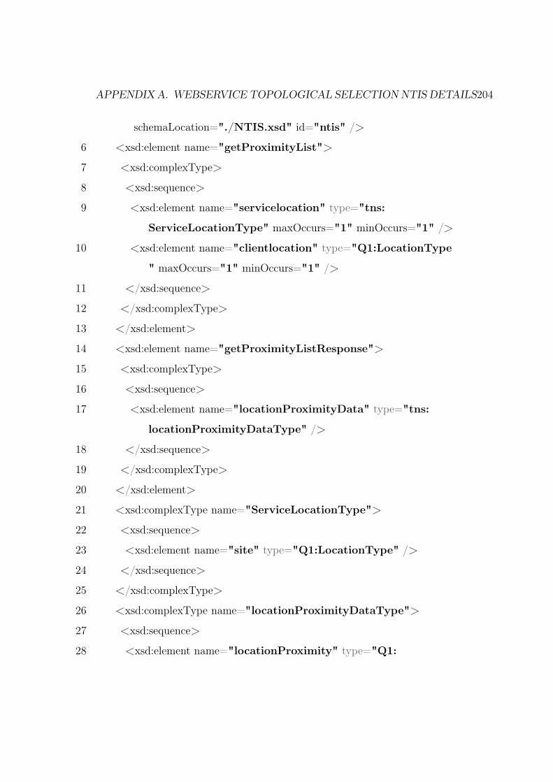
APPENDIX A. WEBSERVICE TOPOLOGICAL SELECTION NTIS DETAILS204
schemaLocation="./NTIS.xsd" id="ntis" />
6 <xsd:element name="getProximityList">
7 <xsd:complexType>
8 <xsd:sequence>
9 <xsd:element name="servicelocation" type="tns:
ServiceLocationType" maxOccurs="1" minOccurs="1" />
10 <xsd:element name="clientlocation" type="Q1:LocationType
" maxOccurs="1" minOccurs="1" />
11 </xsd:sequence>
12 </xsd:complexType>
13 </xsd:element>
14 <xsd:element name="getProximityListResponse">
15 <xsd:complexType>
16 <xsd:sequence>
17 <xsd:element name="locationProximityData" type="tns:
locationProximityDataType" />
18 </xsd:sequence>
19 </xsd:complexType>
20 </xsd:element>
21 <xsd:complexType name="ServiceLocationType">
22 <xsd:sequence>
23 <xsd:element name="site" type="Q1:LocationType" />
24 </xsd:sequence>
25 </xsd:complexType>
26 <xsd:complexType name="locationProximityDataType">
27 <xsd:sequence>
28 <xsd:element name="locationProximity" type="Q1:
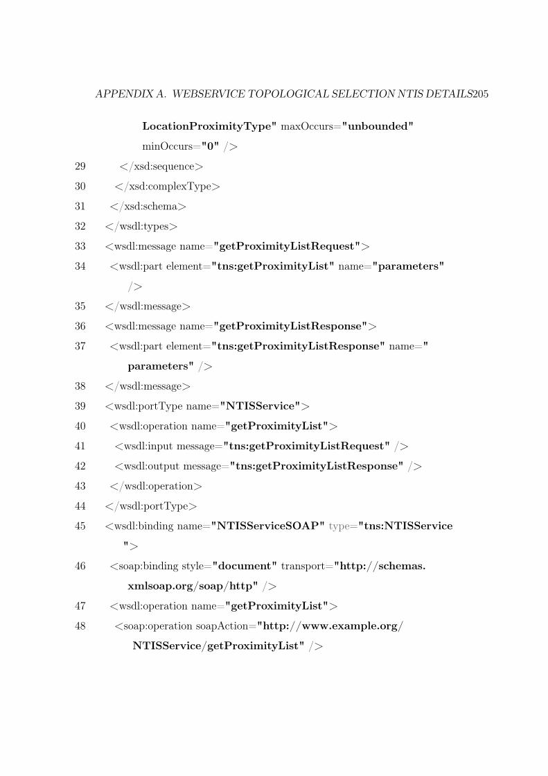
APPENDIX A. WEBSERVICE TOPOLOGICAL SELECTION NTIS DETAILS205
LocationProximityType" maxOccurs="unbounded"
minOccurs="0" />
29 </xsd:sequence>
30 </xsd:complexType>
31 </xsd:schema>
32 </wsdl:types>
33 <wsdl:message name="getProximityListRequest">
34 <wsdl:part element="tns:getProximityList" name="parameters"
/>
35 </wsdl:message>
36 <wsdl:message name="getProximityListResponse">
37 <wsdl:part element="tns:getProximityListResponse" name="
parameters" />
38 </wsdl:message>
39 <wsdl:portType name="NTISService">
40 <wsdl:operation name="getProximityList">
41 <wsdl:input message="tns:getProximityListRequest" />
42 <wsdl:output message="tns:getProximityListResponse" />
43 </wsdl:operation>
44 </wsdl:portType>
45 <wsdl:binding name="NTISServiceSOAP" type="tns:NTISService
">
46 <soap:binding style="document" transport="http://schemas.
xmlsoap.org/soap/http" />
47 <wsdl:operation name="getProximityList">
48 <soap:operation soapAction="http://www.example.org/
NTISService/getProximityList" />

APPENDIX A. WEBSERVICE TOPOLOGICAL SELECTION NTIS DETAILS206
49 <wsdl:input>
50 <soap:body use="literal" />
51 </wsdl:input>
52 <wsdl:output>
53 <soap:body use="literal" />
54 </wsdl:output>
55 </wsdl:operation>
56 </wsdl:binding>
57 <wsdl:service name="NTISService">
58 <wsdl:port binding="tns:NTISServiceSOAP" name="
NTISServiceSOAP">
59 <soap:address location="http://www.example.org/" />
60 </wsdl:port>
61 </wsdl:service>
62 </wsdl:definitions>
Listing A.3: Stock Quote Service WSDL
Appendix B
Qos Language
As part of the thesis, we have written QosLanguage which can be used to
define Qosconstraint on a service.The Xtext Grammer definition is defined
below.
B.0.1 Xtext Grammer
1 grammar org.apache.qos.dsl.QosLanguage with org.eclipse.xtext.
xbase.Xbase
2
3 generate qoslanguage "http://www.apache.org/qos/dsl/QosLang"
4
5 QosLanguage:
6 qoslanguage="QosLanguage" ""
7 concepts+=concept+
8 "";
9
10 concept:
207

APPENDIX B. QOS LANGUAGE 208
11 QosConcept | QosAxiom | QosWebService | QosGoal;
12
13 QosConcept:
14 "QosConcept" ""
15 "name" name=ID
16 "description" des=STRING
17 "unit" unit=ID (type=JvmTypeReference)?
18 "lowerBound" lbound=STRING
19 "upperBound" upbound=STRING
20 "";
21
22 QosAxiom:
23 "QosAxiom" ""
24 "name" name=Axiom
25 "description" desc=STRING
26 "concept" concept=STRING
27 "condition" "" "$value−>"
28 qcond=QConditionExpression
29 ""
30 "";
31
32 QosWebService:
33 "QosWebService" ""
34 "name" name=ID
35 "capability" capability=STRING
36 "qosinterface" ""
37 qosinterfaces=QOSINTERFACES
APPENDIX B. QOS LANGUAGE 209
38 ""
39 "";
40
41 QOSINTERFACES:
42 interfaces+=QOSINTERFACE (’,’ interfaces+=
QOSINTERFACE)∗;
43
44 QOSINTERFACE:
45 name=ID ""
46 "description" des=STRING
47 "value" val=STRING
48 "";
49
50 QosGoal:
51 "QosGoal" ""
52 "name" name=ID
53 "description" descripton=STRING
54 "axiomRequired" "[" axiom=AxiomList "]"
55 "";
56
57 AxiomList:
58 ids+=Axiom (’,’ ids+=Axiom)∗;
59
60 Axiom:
61 ID;
62
63 QConditionExpression:

APPENDIX B. QOS LANGUAGE 210
64 "return" valexp=QExpression;
65
66 QExpression:
67 "(" "value" opc=OpCompare num=Number ")"
68 ;
Listing B.1: Xtext definition of Qos Language
Appendix C
Open Source Contributions
As part of the thesis, we have written framework and application to demon-
strate the principle and also to simulate some of the algorithms. All of the
associated code has been open sourced in a GitHub Repository.
C.0.1 NTIS Repository
The GitHub ntis repository at https://github.com/msikri/ntis is used
to host the NTIS and associated code bases. The NTIS code base contains
the implementation for the following:-
• QOS DSL implementation in Groovy.
• NTIS Server implementation in Groovy (and Java) for the WS PR
Framework Algorithms.
• Inventory Server and Client which are the applications capable of using
WS PR Framework for topological selection and discovery using Java.
The Services are implemented using Spring Framework. We have done some
work using Felix framework for OSGI deployment. OSGI Deployment tools
211

APPENDIX C. OPEN SOURCE CONTRIBUTIONS 212
are not tested completed.
C.0.2 Adaptive Algorithm Repository
The GitHub repository at https://github.com/msikri/simulation hosts
the Algorithms for QoS Awareness and adaptively as outlined in Chapter 8.
The application is implemented in Scala using a Custom Time Series Sim-
ulation software development for this implementation. The software allows
us to emulate the client and server interaction and delays using Async mes-
saging build on top of Akka Framework. The application consists of a same
Simulator and also plotting methods using R. Once the simulator completes
the execution the R library can be used to aggregate the plot the data.
• Setup Scala project.
We have used Scala ide http://scala-ide.org/ for building the sim-
ulator system. But any Scala aware editor would work.
• Modify the experiment for execution.
The experiment or simulation setup is done in Creator2.scala https://
github.com/msikri/simulation/blob/master/expt2/src/main/scala/
org/apache/ntis/sim/base/creator/Creator2.scala. The line no
47-53 defines the Qos Goal for the experiment. Based on the need, we
need to select one of them.
• Running the experiment.
The simulation can be executing by running Exp2App.scala https://
github.com/msikri/simulation/blob/master/expt2/src/main/scala/
org/apache/ntis/sim/base/Exp2App.scala. It results in generation
of metrics.txt file (location user.home/sim/metric.txt). The metrics
APPENDIX C. OPEN SOURCE CONTRIBUTIONS 213
file contains the cost and Rtt readings as observed on the clients at the
various times during the experiment.
• Data Cleanup.
The data cleanup setup involves taking up metric files and cleaning
it and converting it into csv format for analysis and plotting. The
cleanup operation is carried out by DataClean.scala https://github.
com/msikri/simulation/blob/master/base1/src/main/scala/org/
apache/ntis/sim/data/DataClean.scala . We should execute Dat-
aClean.scala for generation of processed files clientRttall.csv location
(user.home/sim/process/clientRttall.csv) and clientCostall.csv loca-
tion (user.home/sim/process/clientCostall.csv).
• Plotting the Graphs
The data is plotted using Rproject/ggplotscript.R. The script also as-
sumes the location of the files clientRttall.csv and clientRttall.csv as
defined above. It uses the time series data in the csv files and plots the
corresponding time series graphs for cost and Rtt respectively.
For each set of experiment, the Creator2.scala need to be modified and
to be reexecuted.
Bibliography
[1] FEAPO | Federation of Enterprise Architecture Professional Organiza-
tions. http://feapo.org/, 2011.
[2] Gartner. Enterprise architecture (ea). http://www.gartner.com/
it-glossary/enterprise-architecture-ea/, 2013.
[3] J. McGovern. A Practical Guide to Enterprise Architecture. The Coad
series. Prentice Hall PTR, 2004.
[4] Aniruddha Gokhale, Bharat Kumar, and Arnaud Sahuguet. Reinvent-
ing the wheel? corba vs. web services. In Proceedings of international
world wide Web conference, 2002.
[5] Christopher Kistasamy, Alta van der Merwe, and Andre de la Harpe.
The Relationship between Service Oriented Architecture and En-
terprise Architecture. In 2010 14th IEEE International Enterprise
Distributed Object Computing Conference Workshops, pages 129–137.
IEEE, oct 2010.
[6] Hamid Tohidi. Modelling of business services in service oriented enter-
prises. Procedia Computer Science, 3:1147–1156, 2011.
214

BIBLIOGRAPHY 215
[7] J. Schelp and Stephan Aier. SOA and EA - Sustainable Contributions
for Increasing Corporate Agility. In 2009 42nd Hawaii International
Conference on System Sciences, pages 1–8. IEEE, 2009.
[8] Institute For Enterprise Architecture Developments (IFEAD).
Enterprise Architecture & Services Oriented Enter-
prise (SOE). http://www.enterprise-architecture.
info/Images/ServicesOrientedEnterprise/
EA_Services-Oriented-Enterprise1.htm.
[9] Ds Linthicum. Cloud Computing and SOA Convergence in Your En-
terprise: A Step-by-Step Guide. Pearson Education, 2009.
[10] Xiaolong Yang and Huimin Zhang. Cloud Computing and SOA Con-
vergence Research. In 2012 Fifth International Symposium on Compu-
tational Intelligence and Design, volume 1, pages 330–335. IEEE, oct
2012.
[11] Huimin Zhang and Xiaolong Yang. Cloud computing architecture
based-on SOA. In Proceedings - 2012 5th International Symposium on
Computational Intelligence and Design, ISCID 2012, volume 1, pages
369–373, 2012.
[12] Jayavardhana Gubbi, Rajkumar Buyya, Slaven Marusic, and
Marimuthu Palaniswami. Internet of Things (IoT): A vision, archi-
tectural elements, and future directions. Future Generation Computer
Systems, 29(7):1645–1660, sep 2013.
[13] Roberto Chinnici, Jean-Jacques Moreau, Arthur Ryman, and Sanjiva
Weerawarana. Web services description language (wsdl) version 2.0
BIBLIOGRAPHY 216
part 1: Core language. World Wide Web Consortium, Recommenda-
tion REC-wsdl20-20070626, June 2007.
[14] BEA, IBM, Microsoft, and SAP AG. Web services policy framework
(WS-Policy). https://www.w3.org/Submission/WS-Policy/, May
2003.
[15] L. Clement, a. Hately, C. von Riegen, and T. Rogers. UDDI Version
3.0.2 UDDI Specification Technical Committee Draft. Oasis committee
draft, OASIS, 2004.
[16] Bijay K. Jayaswal, Peter C. Patton, and Richard E. Zultner. Under-
standing Customer Needs (Digital Short Cut): Software QFD and the
Voice of the Customer. Pearson Education, 2003.
[17] Monika Sikri and Rajkumar Gell. Derivation of agile SOA requirements
using collaborative QFD. Int. J. Collaborative Enterprise, pages 234–
248, 2014.
[18] Monika Sikri. Web Service Selection Using Topological Metadata. Ad-
vances in Computer Engineering (ACE), 2010 International Confer-
ence on, pages 247–251, jun 2010.
[19] Monika Sikri. Design of Domain Specific Language for Web Services
QoS Constraints Definition. In VinuV Das, Gylson Thomas, and Ford
Lumban Gaol, editors, Information Technology and Mobile Communi-
cation, volume 147 of Communications in Computer and Information
Science, pages 411–416. Springer Berlin Heidelberg, 2011.
[20] Jeroen J. van der Ham, Freek Dijkstra, Franco Travostino, Hubertus
M a Andree, and Cees T a M de Laat. Using RDF to describe networks.
Future Generation Computer Systems, 22(8):862–867, oct 2006.

BIBLIOGRAPHY 217
[21] N. Bieberstein, S. Bose, L. Walker, and a. Lynch. Impact of service-
oriented architecture on enterprise systems, organizational structures,
and individuals. IBM Systems Journal, 44(4):691–708, 2005.
[22] Michael P. Papazoglou, Paolo Traverso, Schahram Dustdar, and Frank
Leymann. Service-oriented computing: State of the art and research
challenges. Computer, 40(11):38–45, nov 2007.
[23] Robin Cover. Web services description language (wsdl). http://xml.
coverpages.org/wsdl.html.
[24] Robin Cover. Simple Object Access Protocol (SOAP). http://xml.
coverpages.org/soap.html.
[25] Paul Muschamp. An introduction to Web Services. BT Technology
Journal, 22(1):9–18, 2004.
[26] D. Vassilopoulos, T. Pilioura, and A. Tsalgatidou. Distributed tech-
nologies CORBA, Enterprise JavaBeans, Web services: a comparative
presentation. In 14th Euromicro International Conference on Paral-
lel, Distributed, and Network-Based Processing (PDP’06), page 5 pp.
IEEE, 2006.
[27] Apache Software Foundation. Apache thrift. http://thrift.apache.
org/, March 2010.
[28] D Remenyi. Proceedings of the 3rd European Conference on Manage-
ment Leadership and Governance. Number October. Academic Con-
ferences Limited, 2007.
BIBLIOGRAPHY 218
[29] George Pohle and Marc Chapman. IBM’s global CEO report 2006:
business model innovation matters. Strategy & Leadership, 34(5):34–
40, sep 2006.
[30] The Open Group | TOGAFÂő, an Open Group standard. http://
www.opengroup.org/subjectareas/enterprise/togaf/.
[31] Zachman International - The Official Home of The Zachman Frame-
work. http://www.zachman.com/.
[32] Daryl C Plummer, Charles Smulders, Leslie Fiering, Yefim V Natis,
Simon Mingay, Mark Driver, Jackie Fenn, Laura McLellan, and Debbie
Wilson. Gartner’s top predictions for it organizations and users, 2008
and beyond: Going green and self-healing. Gartner Research, 8, 2008.
[33] Girish Juneja, Blake Dournaee, Joe Natoli, and Steve Birkel. Service
Oriented Architecture Demystified: A pragmatic approach to SOA for
the IT executive. September 2007.
[34] Peter M. Mell and Timothy Grance. SP 800-145. The NIST Definition
of Cloud Computing. sep 2011.
[35] Frank D. Macías-Escrivá, Rodolfo Haber, Raul del Toro, and Vicente
Hernandez. Self-adaptive systems: A survey of current approaches,
research challenges and applications. Expert Systems with Applications,
40(18):7267–7279, dec 2013.
[36] G. Denaro, M. Pezzé, D. Tosi, and Daniela Schilling. Towards self-
adaptive service-oriented architectures. In Proceedings of the 2006
workshop on Testing, analysis, and verification of web services and ap-
plications - TAV-WEB ’06, pages 10–16, New York, New York, USA,
jul 2006. ACM Press.

BIBLIOGRAPHY 219
[37] Michael P. Papazoglou, Paolo Traverso, Schahram Dustdar, and Frank
Leymann. Service-Oriented Computing: a Research Roadmap. Inter-
national Journal of Cooperative Information Systems, 17(02):223–255,
jun 2008.
[38] Padmal Vitharana, Kumar Bhaskaran, Hemant Jain, Harry Wang,
Leon Zhao, and Leon Zhao. Service-oriented enterprises and archi-
tectures: state of the art and research opportunities. AMCIS 2007
Proceedings, page 343, 2007.
[39] Grace Lewis, Dennis Smith, and Kostas Kontogiannis. A Research
Agenda for Service-Oriented Architecture (SOA): Maintenance and
Evolution of Service-Oriented Systems, 2010.
[40] Elisabetta Di Nitto, Carlo Ghezzi, Andreas Metzger, Mike Papazoglou,
and Klaus Pohl. A journey to highly dynamic, self-adaptive service-
based applications. Automated Software Engineering, 15(3-4):313–341,
sep 2008.
[41] Michael P Papazoglou, Paolo Traverso, Schahram Dustdar, and Frank
Leymann. Research directions in service-oriented computing. 4a IC-
SOC 2006, page 28, 2006.
[42] Yefim V Natis, Massimo Pezzini, Roy W Schulte, and Kimihiko Iijima.
Predicts 2007: Soa advances. Gartner Group Report, 2006.
[43] Kent Beck, Mike Beedle, Arie Van Bennekum, Alistair Cockburn, Ward
Cunningham, Martin Fowler, James Grenning, Jim Highsmith, Andrew
Hunt, Ron Jeffries, et al. Manifesto for agile software development.
2001.

BIBLIOGRAPHY 220
[44] F. Paetsch, A. Eberlein, and F. Maurer. Requirements engineering and
agile software development. In WET ICE 2003. Proceedings. Twelfth
IEEE International Workshops on Enabling Technologies: Infrastruc-
ture for Collaborative Enterprises, 2003., pages 308–313. IEEE Com-
put. Soc, 2003.
[45] L. Rising and N.S. Janoff. The Scrum software development process
for small teams. IEEE Software, 17(4):26–32, 2000.
[46] B. Boehm. Get ready for agile methods, with care. Computer, 35(1):64–
69, 2002.
[47] Jordan Barlow, Justin Giboney, Mark J Keith, David Wilson, Ryan
Schuetzler, Paul Benjamin Lowry, and Anthony Vance. Overview and
Guidance on Agile Development in Large Organizations. SSRN Elec-
tronic Journal, aug 2011.
[48] Amr Elssamadisy. Xp on a large project–a developerâĂŹs view. Pro-
ceedings of XP/Agile Universe, Raleigh, NC, 2001.
[49] K. Mohan and B. Ramesh. How extreme does extreme programming
have to be? Adapting XP practices to large-scale projects. In 37th
Annual Hawaii International Conference on System Sciences, 2004.
Proceedings of the, page 10 pp. IEEE, 2004.
[50] Cara Taber and Martin Fowler. An iteration in the life of an xp project.
Cutter IT journal, 13(11):13–21, 2000.
[51] ÂăGabrielle Benefield. Rolling Out Agile in a Large Enterprise. In
Proceedings of the 41st Annual Hawaii International Conference on
System Sciences (HICSS 2008), pages 461–461. IEEE, jan 2008.

BIBLIOGRAPHY 221
[52] Andrea De Lucia and Abdallah Qusef. Requirements Engineering in
Agile Software Development. Journal of Emerging Technologies in Web
Intelligence, 2(3):212–220, aug 2010.
[53] Carter Fred Blum Adum. Representing web services management in-
formation in uddi. http://www.axis.apache.org/axis/, Feb 2004.
[54] Bernhard Hollunder. WS-Policy: On conditional and custom asser-
tions. In 2009 IEEE International Conference on Web Services, ICWS
2009, pages 936–943. IEEE, jul 2009.
[55] Tim Berners-Lee, James Hendler, Ora Lassila, et al. The semantic web.
Scientific american, 284(5):28–37, 2001.
[56] David Martin, Mark Burstein, Jerry Hobbs, Ora Lassila, Drew Mc-
Dermott, Sheila McIlraith, Srini Narayanan, Massimo Paolucci, Bijan
Parsia, Terry Payne, et al. Owl-s: Semantic markup for web services.
W3C member submission, 22:2007–04, 2004.
[57] Dumitru Roman, Uwe Keller, Holger Lausen, Jos de Bruijn, Rubén
Lara, Michael Stollberg, Axel Polleres, Cristina Feier, Cristoph Bussler,
and Dieter Fensel. Web service modeling ontology. Applied ontology,
1(1):77–106, 2005.
[58] Semantic Web Services Initiative Architecture Committee. A semantic
web services architecture. http://www.ai.sri.com/daml/services/
swsa/, Apr 2005.
[59] Kyriakos Kritikos and Dimitris Plexousakis. Semantic QoS-based web
service discovery algorithms. In Proceedings of the 5th IEEE European
Conference on Web Services, ECOWS 07, pages 181–190. IEEE, nov
2007.

BIBLIOGRAPHY 222
[60] Glen Dobson, Russell Lock, and Ian Sommerville. QoSOnt: A qos
ontology for service-centric systems. In Software Engineering and Ad-
vanced Applications, 2005. 31st EUROMICRO Conference, volume
2005, pages 80–87. IEEE, 2005.
[61] Giuseppe Damiano, Ester Giallonardo, and Eugenio Zimeo. OnQoS-
QL: A query language for QoS-based service selection and ranking. In
Elisabetta Nitto and Matei Ripeanu, editors, Lecture Notes in Com-
puter Science (including subseries Lecture Notes in Artificial Intelli-
gence and Lecture Notes in Bioinformatics), volume 4907 LNCS of
Lecture Notes in Computer Science, pages 115–127. Springer-Verlag,
Berlin Heidelberg, 2009.
[62] Gustavo Fortes Tondello and Frank Siqueira. The QoS-MO Ontology
for Semantic QoS Modeling. In Proceedings of the ACM Symposium
on Applied Computing (SAC 2008), pages 2336–2340, New York, New
York, USA, mar 2008. ACM Press.
[63] Shuyu Li Shuyu Li and Juan Zhou Juan Zhou. The WSMO-QoS Se-
mantic Web Service Discovery Framework. In 2009 International Con-
ference on Computational Intelligence and Software Engineering, pages
1–5. IEEE, dec 2009.
[64] Vuong Xuan Tran. WS-QoSOnto: A QoS ontology for Web services.
In Proceedings of the 4th IEEE International Symposium on Service-
Oriented System Engineering, SOSE 2008, pages 233–238. IEEE, dec
2008.
BIBLIOGRAPHY 223
[65] Chen Zhou, Liang-Tien Chia, and Bu-Sung Lee. QoS-Aware and Fed-
erated Enhancement for UDDI. International Journal of Web Services
Research, 1(2):58–85, 2004.
[66] M. Adel Serhani, Rachida Dssouli, Abdelhakim Hafid, and Houari
Sahraoui. A QoS broker based architecture for efficient web services se-
lection. In Proceedings - 2005 IEEE International Conference on Web
Services, ICWS 2005, volume 2005, pages 113–120. IEEE, 2005.
[67] Anup Kumar, Ayman El-Geniedy, and Sanjuli Agarwal. A generalized
framework for providing QoS based registry in service oriented architec-
ture. In Proceedings - 2005 IEEE International Conference onServices
Computing, SCC 2005, volume I, pages 295–301. IEEE, 2005.
[68] Ziqiang Xu, Patrick Martin, Wendy Powley, and Farhana Zulkernine.
Reputation-enhanced QoS-based web services discovery. In Proceedings
- 2007 IEEE International Conference on Web Services, ICWS 2007,
pages 249–256. IEEE, jul 2007.
[69] Gang Ye, Chanle Wu, Jun Yue, and Shi Cheng. A QoS-Aware Model
for Web Services Discovery. In 2009 First International Workshop on
Education Technology and Computer Science, volume 3, pages 740–744.
IEEE, 2009.
[70] Asir S Vedamuthu, David Orchard, Frederick Hirsch, Maryann Hondo,
Prasad Yendluri, Toufic Boubez, and ÃIJmit YalÃğinalp. Web services
policy framework (wspolicy). http://www.w3.org/TR/ws-policy,
September 2007.
[71] Diego Zuquim Guimaraes Garcia Diego Zuquim Guimaraes Garcia and
Maria Beatriz Felgar De Toledo Maria Beatriz Felgar De Toledo. A

BIBLIOGRAPHY 224
Web Service Architecture Providing QoS Management. In 2006 Fourth
Latin American Web Congress, pages 189–198. IEEE, oct 2006.
[72] Markus Mathes, Steffen Heinzl, and Bernd Freisleben. WS-
TemporalPolicy: A WS-policy extension for describing service prop-
erties with time constraints. In Proceedings - International Computer
Software and Applications Conference, pages 1180–1186. IEEE, 2008.
[73] Apache Software Foundation. Apache axis 1.4. http://www.axis.
apache.org/axis/, March 2006.
[74] Jae Choi, D. Nazareth, and H. Jain. The impact of soa implementation
strategies on business value and agility: A systems dynamics approach.
In Advanced Information Management and Service (IMS), 2010 6th
International Conference on, pages 1–6, Nov 2010.
[75] Vladimir Tosic. Autonomic Business-Driven Dynamic Adaptation of
Service-Oriented Systems and the WSPolicy4MASC Support for Such
Adaptation. International Journal of Systems and Service-Oriented
Engineering, 1(1):79–95, 2010.
[76] Monika Sikri and Rajkumar Gell. Adaptive SOA stack and discovery
framework for redundant services. In Industrial and Information Sys-
tems (ICIIS), 2014 9th International Conference on, pages 1–6. IEEE,
2014.
[77] Andrea DAmbrogio. A Model-driven WSDL Extension for Describing
the QoS ofWeb Services. In 2006 IEEE International Conference on
Web Services (ICWS’06), pages 789–796. IEEE, 2006.

BIBLIOGRAPHY 225
[78] OMG. OMG Unified Modeling Language (OMG UML), Superstruc-
ture, Version 2.4.1. http://www.omg.org/spec/UML/2.4.1, August
2011.
[79] Changying Dai and Zhibin Wang. A flexible extension of WSDL to de-
scribe non-functional attributes. In 2010 2nd International Conference
on E-Business and Information System Security, EBISS2010, pages
52–55. IEEE, may 2010.
[80] N. Parimala and Anu Saini. Web service with criteria: Extending
WSDL. In 2011 Sixth International Conference on Digital Information
Management, pages 205–210. IEEE, September 2011.
[81] Robin Cover. HP Contributes Web Services Management Framework
Specification to OASIS TC. Oasis, 2003.
[82] Alexander Keller and Heiko Ludwig. The WSLA Framework: Specify-
ing and Monitoring Service Level Agreements for Web Services. Journal
of Network and Systems Management, 11(1):57–81, March 2003.
[83] Nicholas Metropolis, Arianna W. Rosenbluth, Marshall N. Rosenbluth,
Augusta H. Teller, and Edward Teller. Equation of State Calcula-
tions by Fast Computing Machines. The Journal of Chemical Physics,
21(6):1087–1092, jun 1953.
[84] Kyriakos E Kritikos. Qos-based web service description and discovery.
PhD thesis, University of Crete, 2008.
[85] Qian Ma, Hao Wang, Ying Li, Guotong Xie, and Feng Liu. A semantic
QoS-aware discovery framework for web services. In Proceedings of the
IEEE International Conference on Web Services, ICWS 2008, pages
129–136. IEEE, sep 2008.

BIBLIOGRAPHY 226
[86] Xia Wang, Tomas Vitvar, Mick Kerrigan, and Ioan Toma. A qos-aware
selection model for semantic web services. In Asit Dan and Winfried
Lamersdorf, editors, Service-Oriented Computing âĂŞ ICSOC 2006,
volume 4294 of Lecture Notes in Computer Science, pages 390–401.
Springer Berlin Heidelberg, 2006.
[87] Monika Sikri and Rajkumar Gell. Service discovery for soa systems with
topological and qos constraints. In Computer Networks and Security,
volume 147 of Communications in Computer and Information Science,
pages 477–481. Elsevier, Gurgaon, New Delhi, India, 2014.
[88] Elzavita MacLennan and Jean-Paul Van Belle. Factors affecting the
organizational adoption of service-oriented architecture (soa). Infor-
mation Systems and e-Business Management, 12(1):71–100, 2014.
[89] M. Burstein, C. Bussler, T. Finin, M.N. Huhns, M. Paolucci, a.P.
Sheth, S. Williams, and M. Zaremba. A semantic Web services ar-
chitecture. IEEE Internet Computing, 9(5):72–81, sep 2005.
[90] Dominic Greenwood, Margaret Lyell, Ashok Mallya, and Hiroki Sug-
uri. The IEEE FIPA approach to integrating software agents and web
services. In Proceedings of the 6th international joint conference on
Autonomous agents and multiagent systems - AAMAS ’07, volume 5,
page 1, New York, New York, USA, may 2007. ACM Press.
[91] Onder Gurcan, Geylani Kardas, OzgÃijr Gumus, ErdemEser Ekinci,
and Oguz Dikenelli. An mas infrastructure for implementing swsa based
semantic services. In Jingshan Huang, Ryszard Kowalczyk, Zakaria
Maamar, David Martin, Ingo MÃijller, Suzette Stoutenburg, and Ka-
tiaP. Sycara, editors, Service-Oriented Computing: Agents, Semantics,
BIBLIOGRAPHY 227
and Engineering, volume 4504 of Lecture Notes in Computer Science,
pages 118–131. Springer-Verlag, Berlin Heidelberg, 2007.
[92] P Sathyavathy, C Sneha, B Uma, S Swamynathan, and T V Geetha.
Semantic and QoS based Web Service Selection using a Multi Agent
System. In Iicai, pages 2521–2533, 2005.
[93] RDF Working Group. Resource description framework(rdf). http:
//www.w3.org/standards/techs/rdf, Feb 2014.
[94] Xia Wang, Tomas Vitvar, Mick Kerrigan, and Ioan Toma. A qos-
aware selection model for semantic web services. In Service-Oriented
Computing–ICSOC 2006, pages 390–401. Springer-Verlag, Berlin Hei-
delberg, 2006.
[95] MohamedAnis Zemni, Salima Benbernou, and Manuel Carro. A soft
constraint-based approach to qos-aware service selection. In PaulP.
Maglio, Mathias Weske, Jian Yang, and Marcelo Fantinato, editors,
Service-Oriented Computing, volume 6470 of Lecture Notes in Com-
puter Science, pages 596–602, Berlin Heidelberg, 2010. Springer-Verlag.
[96] Kyriakos Kritikos and Dimitris Plexousakis. Owl-q for semantic qos-
based web service description and discovery. In Proceedings of the
SMR2 2007 Workshop on Service Matchmaking and Resource Retrieval
in the Semantic Web, pages 123–137, 2007.
[97] Jae Choi, Derek Nazareth, and Hemant Jain. The impact of SOA
implementation strategies on business value and agility: A systems
dynamics approach. 2010 6th International Conference on Advanced
Information Management and Service (IMS), pages 1–6, 2010.
BIBLIOGRAPHY 228
[98] B. Benatallah, A.H.H. Ngu, M. Dumas, J. Kalagnanam, and H. Chang.
QoS-aware middleware for Web services composition. IEEE Transac-
tions on Software Engineering, 30(5):311–327, may 2004.
[99] David Harel and Amnon Naamad. The STATEMATE semantics of
statecharts. ACM Transactions on Software Engineering and Method-
ology, 5(4):293–333, oct 1996.
[100] Raja Afandi, Jianqing Zhang, and Carl Gunter. AMPol-Q: Adaptive
Middleware Policy to Support QoS. In Service-Oriented Computing
âĂŞ ICSOC 2006, pages 165–178. 2006.
[101] Raja Afandi, Jianqing Zhang, Munawar Hafiz, and Carl Gunter. AM-
Pol: Adaptive Messaging Policy. In 2006 European Conference on Web
Services (ECOWS’06), pages 53–64. IEEE, 2006.
[102] Kaarthik Sivashanmugam, Kunal Verma, Amit Sheth, and John Miller.
Adding Semantics to Web Services Standards, 2003.
[103] E. Sirin, B. Parsia, and J. Hendler. Filtering and selecting semantic
Web services with interactive composition techniques. IEEE Intelligent
Systems, 19(4):42–49, jul 2004.
[104] D. Ardagna and B. Pernici. Adaptive Service Composition in Flexible
Processes. IEEE Transactions on Software Engineering, 33(6):369–384,
jun 2007.
[105] Paolo Atzeni, Tiziana Catarci, and Barbara Pernici. Multi-channel
Adaptive Information Systems. World Wide Web, 10(4):345–347, jun
2007.

BIBLIOGRAPHY 229
[106] Danilo Ardagna, Marco Comuzzi, Enrico Mussi, Barbara Pernici, and
Pierluigi Plebani. PAWS: A framework for executing adaptive web-
service processes. IEEE Software, 24(6):39–46, nov 2007.
[107] Pierluigi Plebani and Barbara Pernici. URBE: Web service retrieval
based on similarity evaluation. IEEE Transactions on Knowledge and
Data Engineering, 21(11):1629–1642, nov 2009.
[108] Mohammad Alrifai, Thomas Risse, and Wolfgang Nejdl. A hybrid
approach for efficient Web service composition with end-to-end QoS
constraints. ACM Transactions on the Web, 6(2):1–31, may 2012.
[109] Krzysztof ZieliÅĎski, Tomasz SzydÅĆo, Robert Szymacha, Jacek
KosiÅĎski, Joanna KosiÅĎska, and Marcin Jarzab. Adaptive SOA
solution stack. IEEE Transactions on Services Computing, 5(2):149–
163, apr 2012.
[110] Qianhui Liang, XindongWu, and Hoong Chuin Lau. Optimizing service
systems based on application-level QoS. IEEE Transactions on Services
Computing, 2(2):108–121, apr 2009.
[111] M.-T. Schmidt, B. Hutchison, P. Lambros, and R. Phippen. The En-
terprise Service Bus: Making service-oriented architecture real. IBM
Systems Journal, 44(4):781–797, 2005.
[112] Jianwei Yin, Hanwei Chen, Shuiguang Deng, Zhaohui Wu, and Calton
Pu. A Dependable ESB Framework for Service Integration. IEEE
Internet Computing, 13(2):26–34, mar 2009.
[113] Albert Benveniste, Claude Jard, Ajay Kattepur, Sidney Rosario, and
John A. Thywissen. QoS-aware management of monotonic service or-
chestrations. Formal Methods in System Design, 44(1):1–43, jul 2013.

BIBLIOGRAPHY 230
[114] Huiyuan Zheng, Jian Yang, Weiliang Zhao, and Athman Bouguettaya.
Qos analysis for web service compositions based on probabilistic qos.
In Service-Oriented Computing, pages 47–61. Springer, 2011.
[115] PengCheng Xiong, YuShun Fan, and MengChu Zhou. A Petri Net
Approach to Analysis and Composition of Web Services. IEEE Trans-
actions on Systems, Man, and Cybernetics - Part A: Systems and Hu-
mans, 40(2):376–387, mar 2010.
[116] Jae Choi, Derek L. Nazareth, and Hemant K. Jain. The Impact of
SOA Implementation on IT-Business Alignment: A System Dynamics
Approach. ACM Trans. Manage. Inf. Syst., 4(1):3:1–3:22, 2013.
[117] Pasquale Iocola. When legacy meets SOA: Achieving business agility
by integrating new technology with existing software asset. In Proceed-
ings of the 1st Annual 2007 IEEE Systems Conference, pages 318–325.
IEEE, apr 2007.
[118] Yoji Akao. QFD: Quality Function Deployment - Integrating Customer
Requirements into Product Design. 2004.
[119] G. Herzwurm, S. Schockert, and W. Pietsch. QFD for customer-focused
requirements engineering. In Journal of Lightwave Technology, pages
330–338. IEEE Comput. Soc, 2003.
[120] Glenn H Mazur. Blitz QFDÂő âĂŞ The Modern Matrix-Free Way to
Profit Improvement. Quality management forum, 37(3):11–12, 2011.
[121] Glenn HMazur. Blitz QFDÂő âĂŞ The Lean Approach to New Product
Development. In Quality Improvement, 2010. ISQFD’10. ASQ World
conference on, Anaheim, CA, may 2012. QFD Institute.

BIBLIOGRAPHY 231
[122] Jim Womack. Gemba walk. Lean Enterprise Institute, USA, 2011.
[123] Mohan Tanniru Ting-Peng Liang. Customer-Centric Information Sys-
tems. Journal of Management Information Systems, 23(3):9–15, 2007.
[124] P. K. Mills and J. H. Morris. Clients as "Partial" Employees of Service
Organizations: Role Development in Client Participation., 1986.
[125] F. Reichheld and W. E. Sasser Jr. Zero defections: quality comes to
services. Harvard business review, 68(5):105–111, 1990.
[126] Ely Dahan and John R. Hauser. The virtual customer. Journal of
Product Innovation Management, 19(5):332–353, sep 2002.
[127] D. E. Cox and H. Kreger. Management of the service-oriented-
architecture life cycle. IBM Systems Journal, 44(4):709–726, 2005.
[128] Youngkon Lee. QoS Management for SOA by Synchronizing Quality
Context in UDDI. In 2008 Second International Conference on Future
Generation Communication and Networking Symposia, pages 17–22.
IEEE, dec 2008.
[129] L O’Brien, P Merson, and L Bass. Quality attributes for service-
oriented architectures. In Proceedings - ICSE 2007 Workshops: In-
ternational Workshop on Systems Development in SOA Environments,
SDSOA’07, SDSOA ’07, pages 3—-, Washington, DC, USA, 2007.
IEEE Computer Society.
[130] Rashina Hoda, Philippe Kruchten, James Noble, and Stuart Marshall.
Agility in context. ACM SIGPLAN Notices, 45(10):74, oct 2010.
BIBLIOGRAPHY 232
[131] Glenn H Stansfield Kim, Cole Jeff and Mazur, Cole Jeff Stansfield Kim,
and Glenn H Mazur. Complex IT Design using both Traditional QFD
and Blitz QFD. In 22nd Symposium on QFD, pages 139–164, 2010.
[132] Thomas L. Saaty. Decision making âĂŤ the Analytic Hierarchy and
Network Processes (AHP/ANP), 2004.
[133] Geoff Coyle. Instructor âĂŹ s Manual Practical Strategy : Structured
Tools and Techniques, volume 4. Financial Times Prentice Hall, 2004.
[134] Eva Heiskanen. USER INVOLVEMENT AND ENTREPRENEURIAL
ACTION. An Interdiscliplinary Journal on Humans in ICT Environ-
ments, 3:167–187, 2007.
[135] Subhas Chandra Misra, Vinod Kumar, and Uma Kumar. Identifying
some important success factors in adopting agile software development
practices. Journal of Systems and Software, 82(11):1869–1890, nov
2009.
[136] Abdelkarim Erradi, Sriram Anand, and Naveen Kulkarni. Evaluation
of strategies for integrating legacy applications as services in a service
oriented architecture. In Services Computing, 2006. SCC’06. IEEE
International Conference on, pages 257–260. IEEE, 2006.
[137] Chunhua Gu and Xueqin Zhang. An SOA Based Enterprise Applica-
tion Integration Approach. In 2010 Third International Symposium on
Electronic Commerce and Security, pages 324–327. IEEE, jul 2010.
[138] Armando Fox and David Patterson. Engineering Long-Lasting Soft-
ware: An Agile Approach Using SaaS and Cloud Computing, Alpha
Edition. Strawberry Canyon LLC, 2012.

BIBLIOGRAPHY 233
[139] Yassaman Khodadadeh and Nazanin Mohammadpur. Redesigning a
product based on Voice of Customer. International Association of So-
cieties of Design Research 2009, 2009.
[140] B. Verheecke, W. Vanderperren, and V. Jonckers. Unraveiliny crossout-
ting concerns in Web services middleware. IEEE Software, 23(1):42–50,
jan 2006.
[141] Marc N. Haines and William Haseman. Service-oriented architecture
adoption patterns. In Proceedings of the 42nd Annual Hawaii Interna-
tional Conference on System Sciences, HICSS, 2009.
[142] Erik Christensen, Francisco Curbera, Greg Meredith, and Sanjiva
Weerawarana. Web Services Description Language (WSDL) 1.1, 2001.
[143] Dan Brickley and R.V. Guha. RDF Vocabulary Description Language
1.0: RDF Schema, 2004.
[144] G Klyne and Jj Carroll. Resource description framework (RDF): Con-
cepts and abstract syntax. W3C Recommendation, 2004. World Wide
Web Consortium, 10:1—-20, 2004.
[145] Michael T Goodrich and Roberto Tamassia. Algorithm design. Wiely
India, 2002.
[146] Stephan Grimm, Boris Motik, and Chris Preist. The Semantic Web:
Research and Applications. In The Semantic Web: Research and Ap-
plications, volume 4011, pages 575–589. 2006.
[147] Sheila a. McIlraith and David L. Martin. Bringing semantics to Web
services. IEEE Intelligent Systems, 18(1):90–93, 2003.

BIBLIOGRAPHY 234
[148] Juhnyoung Lee and Richard Goodwin. Ontology management for large-
scale enterprise systems. Electronic Commerce Research and Applica-
tions, 5(1):2–15, mar 2006.
[149] Robert Meersman and Zahir Tari, editors. On the Move to Meaningful
Internet Systems 2006: CoopIS, DOA, GADA, and ODBASE, volume
4275 of Lecture Notes in Computer Science. Springer Berlin Heidelberg,
Berlin, Heidelberg, 2006.
[150] D. Fensel, F. M. Facca, E. Simperl, and I. Toma. Semantic Web Ser-
vices. Semantic Web Services, 1(1):87–104, 2011.
[151] David Martin, Mark Burstein, Jerry Hobbs, Ora Lassila, Drew Mc-
Dermott, Sheila McIlraith, Srini Narayanan, Massimo Paolucci, Bijan
Parsia, Terry R. Payne, Evren Sirin, Naveen Srinivasan, and Katia
Sycara. OWL-S: Semantic Markup for Web Services, 2004.
[152] Jos de Bruijn, Holger Lausen, Axel Polleres, and Dieter Fensel. The
WSML Rule Languages for the Semantic Web. In W3C Workshop
on Rule Languages for Interoperability, 2005.
[153] José María García, David Ruiz, Antonio Ruiz-Cortés, Octavio Martín-
Díaz, and Manuel Resinas. An Hybrid, QoS-Aware Discovery of Seman-
tic Web Services Using Constraint Programming. In ServiceOriented
Computing âĂŞ ICSOC 2007, volume 4749, pages 69–80. 2007.
[154] Groovy: A dynamic language for the java platform. http://groovy.
codehaus.org/, 2003. Groovy is an object-oriented programming lan-
guage for the Java platform.
[155] V Subramaniam. Programming Groovy: Dynamic Productivity for the
Java Developer. 2008.
BIBLIOGRAPHY 235
[156] S. Devijer and S. Devijer. A Groovy DSL from scratch in 2 hours -
Groovy Zone, 2008.
[157] Kyriakos Kritikos and Dimitris Plexousakis. Requirements for QoS-
based Web service description and discovery. In IEEE Transactions on
Services Computing, volume 2, pages 320–337, 2009.
[158] Asit Dan, Robert D. Johnson, and Tony Carrato. SOA service reuse by
design. In Proceedings of the 2nd international workshop on Systems
development in SOA environments - SDSOA ’08, page 25, New York,
New York, USA, may 2008. ACM Press.
[159] J Schekkerman. What you all need to know about services orienta-
tion! structuring the enterprise around services. the differences between
hype, hope and reality, 2006.
[160] Yutu Liu, Anne H Ngu, and Liang Z Zeng. QoS computation and
policing in dynamic web service selection. In Proceedings of the 13th
international World Wide Web conference on Alternate track papers
& posters, pages 66–73, New York, New York, USA, may 2004. ACM
Press.
[161] Elzavita MacLennan and Jean Paul Van Belle. Factors affecting the
organizational adoption of service-oriented architecture (SOA). Infor-
mation Systems and e-Business Management, 12(1):71–100, 2014.
[162] Hoang Tuy. Convex Analysis and Global Optimization. Springer Science
& Business Media, 2013.
[163] J. N. Luftman, P. R. Lewis, and S. H. Oldach. Transforming the enter-
prise: The alignment of business and information technology strategies.
IBM Systems Journal, 32(1):198–221, 1993.

BIBLIOGRAPHY 236
[164] George P.H. Styan. Hadamard products and multivariate statistical
analysis. Linear Algebra and its Applications, 6:217–240, January 1973.
[165] Stephen Boyd and Lieven Vandenberghe. Convex Optimization. Cam-
bridge University Press, 2004.
[166] José María García, Martin Junghans, David Ruiz, Sudhir Agarwal, and
Antonio Ruiz-Cortés. Integrating semantic Web services ranking mech-
anisms using a common preference model. Knowledge-Based Systems,
49:22–36, sep 2013.
[167] Zibin Zheng and Michael R. Lyu. QoS Management of Web Services.
Springer, 2013.
[168] Domenico Bianculli, Walter Binder, Mauro Luigi Drago, and Carlo
Ghezzi. ReMan: A pro-active reputation management infrastructure
for composite Web services. In 2009 IEEE 31st International Confer-
ence on Software Engineering, pages 623–626. IEEE, may 2009.
[169] Ping Wang, Kuo-Ming Chao, Chi-Chun Lo, Ray Farmer, and Pu-Tsun
Kuo. A Reputation-Based Service Selection Scheme. In 2009 IEEE
International Conference on e-Business Engineering, pages 501–506.
IEEE, 2009.
[170] Monika Sikri and Gell Rajkumar. Service Discovery for SOA Systems
with Topological and QoS Constraints. In Computer Networks and
Security, volume 147 of Communications in Computer and Information
Science, pages 477–481. Elsevier, Gurgaon, New Delhi, India, 2014.
[171] Mitsuo Nagamachi. Kansei engineering: a new ergonomic consumer-
oriented technology for product development. International Journal of
industrial ergonomics, 15(1):3–11, 1995.

BIBLIOGRAPHY 237
[172] Dean H Stamatis. Failure mode and effect analysis: FMEA from theory
to execution. ASQ Quality Press, 2003.

Biodata
238

Rajkumar Gell (Supervisor)
Rajkumar Gell has been associated with Cisco Systems for over 11 years in whichnearly 8 years he played the role of Test Manager for doing different types oftesting (Functional, Performance, Integration, End to End System Testing.) forsoftware enterprise applications - ERP, Web Applications, SOA, Web Services,Cloud Services. He is currently leading a global team with few specific functionswithin Information Security Team at Cisco Systems, based at Bangalore.
Work Experience
Current-2010 Service Manager at Cisco Systems, Bangalore2010-2003 Program Manager at Satyam Computer Services Pvt Ltd2003-2002 Testing & QA Manager at Lumley Technology India2002-2000 Team Leader at DanLaw Technologies India2000-1997 Scientist Fellow at National Environmental Engineering Research
Institute, Nagpur1997-1994 Research Associate at Jawaharlal Nehru Center for Advanced Sci-
entific Research
Education
2003 M.S (Software Systems) from BITS,Pilani1994 PhD (Atmospheric Sc. & Technology) from IIT, Kharagpur1989 M.Tech (Atmospheric Sc. & Technology) from IIT, Kharagpur
Publication
• G. Rajkumar, R. S. Saraswat and B. Chakravarty 1994: Boundary-LayerMeteorology, Kluwer Academic Publishers, Volume 68, Numbers 1-2, 131-137: Thermodynamic structure of the monsoon boundary layer under the influenceof a large-scale depression.
• G Rajkumar & R Narasimha 1996: Statistical analysis of the position of the mon-soon trough Journal of Earth System Science Vol 105, no.3, 343-355
• G Rajkumar, R Narasimha, S P Singhal & B S Gera 1996:Thermal and windstructures of the monsoon trough boundary layer Journal of Earth Systems Science,Vol.105, no.3, 325-341
Personal Data
Office Address Cessna Business Park, Kadubeesanahalli Varthur Hobli,Outer Ring Road, Bangalore 560087
Phone 9986037366Email [email protected]
239
Monika Sikri
Eleven years of experience in Information Technology with a focus in EnterpriseApplication Integration Domain (EAI), SOA and Middleware Technologies. Strongknowledge in Object Oriented analysis and Design .Proficiency in Oracle andRDBMS concepts. Knowledge of Internet Technologies such as Developing Server& Middle tier applications using Java, Tibco.
Work Experience
Current-2006 Architect at Cisco Systems, Bangalore2006-2005 Systems Engineer at TCS2005-2004 Software Engineer at Infogain India Pvt Ltd,India
Education
2004 Master of Technology (Computer Science) from JNU,Delhi2001 Bachelor of Technology (Computer Science and IT ) from I.E.T, Bareilly
Profession Achievements
• Awarded as Cisco STAR two times.
• Awarded as Cisco SPARK.
• Bronze Certified BOST Professional.
Academic Achievements
• Gold Medalist in B.Tech (DGPA: 9.23/10)) and M.Tech (CGPA 9/9 )
Personal Data
Office Address Cessna Business Park, Kadubeesanahalli Varthur Hobli,Outer Ring Road, Bangalore 560087
Email [email protected]
240