agenda draft planning committee - nerc.com highlights and minutes...
TRANSCRIPT

Agenda Draft Planning Committee September 11, 2018 | 1:00 – 5:00 p.m. Central September 12, 2018 | 8:00 a.m. – noon Central Hyatt Regency Minneapolis 1300 Nicollet Mall Minneapolis, MN 55403 Conference Room: Nicollet D (First Floor) Welcome and Introductions NERC Antitrust Compliance Guidelines and Public Announcement Agenda
1. Remarks and Reports
a. Chair Report – Brian Evans-Mongeon
i. Welcome New Planning Committee Members
(1) New member introductions
(2) Returning member introductions
ii. August Board of Trustees Meeting Update
iii. New Distributed Energy Resources (DER) working group – System Planning Impacts of DER (SPIDER)
iv. Committee leadership changes and recognitions
(1) Performance Analysis Subcommittee leadership succession
(2) Transmission Availability Data System Working Group (TADSWG) vice chair
(3) Misoperations Information Data Analysis System Working Group (MIDASWG) leadership
v. Update on Action Plan for Addressing Assessment Report Recommendations
2. PCEC Election
a. Todd Snitchler is nominated to fill vacancy created by Russell Schussler’s departure
3. Consent Agenda – Approve
a. June 5-6, 2018 Meeting Minutes

Agenda – Planning Committee – September 11-12, 2018 2
b. State of Reliability (SOR) 2018 – Endorsed by email vote on June 8, 2018
c. Transmission Availability Data System Working Group (TADSWG) Amended Scope – Approve
4. Subcommittee Leadership Reports and PC Work Plan Updates*
a. Performance Analysis Subcommittee (PAS) – Paul Kure
i. Generator Availability Data System Working Group (GADSWG)
ii. Transmission Availability Data System Working Group (TADSWG)
iii. Demand Response Data System Working Group (DADSWG)
iv. Misoperations Information Data and Analysis System Working Group (MIDASWG)
b. Reliability Assessment Subcommittee (RAS) – Tim Fryfogle
i. Probabilistic Assessment Working Group (PAWG)
c. System Protection & Control Subcommittee (SPCS) – Mark Gutzmann
d. Synchronized Measurements Subcommittee (SMS) – Aftab Alam
e. System Analysis and Modeling Subcommittee (SAMS) – Hari Singh
i. Load Modeling Task Force (LMTF)
ii. Power Plant Modeling and Verification Task Force (PPMVTF)
f. Methods for Establishing IROLS Task Force (MEITF) – Wayne Guttormson
g. Inverter Resource Performance Task Force (IRPTF) – Jeff Billo
h. Geomagnetic Disturbance Task Force (GMDTF) – Ian Grant
5. Reliability Guidelines*
a. Methods for Establishing IROLs – Approve – Wayne Guttormson
b. BPS-Connected Inverter-based Resource Performance – Approve – Jeff Billo
c. Power Plant Model Verification for Inverter-Based Resources – Approve – Hari Singh
6. Items for Approval, Endorsement, or Acceptance*
a. IROL Framework Assessment Report – Approve – Hari Singh
7. Discussion Topics– Information*
a. Accelerated Generation Retirements Special Reliability Assessment Report (Draft) Discussion – Mark Olson
b. 2018 Long-Term Reliability Assessment (LTRA) Update and Discussion of Draft Key Findings – John Moura
c. SPIDER Scope Discussion and Working Group Establishment Update – Jeff Billinton
d. Member Roundtable.
Agenda – Planning Committee – September 11-12, 2018 3
i. Topics for discussion include:
(1) Insights from July 31 FERC Technical Conference
(2) Follow-up on DER impact assessment on UFLS/UVLS
(3) Preliminary observations from 2018 summer operations
(4) Applying lessons learned from 2017-2018 winter to upcoming winter season preparations
ii. PC Member topics of interest
8. Closing Remarks – Brian Evans-Mongeon
9. Adjournment
10. Future In-person Meetings
a. December 11-12, 2018 | Atlanta, GA
b. March 5-6, 2019 | Location TBD
c. June 4-5, 2019 | Location TBD
d. September 10-11, 2019 | Location TBD
e. December 10-11, 2019 | Location TBD *Background materials included, if appropriate.
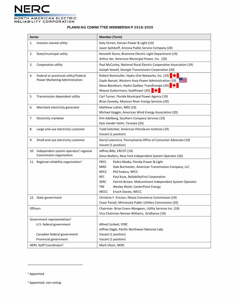
PLANNING COMMITTEE MEMBERSHIP 2018-2020
1 Appointed
2 Appointed, non-voting
Sector Member (Term)
1. Investor-owned utility Katy Onnen, Kansas Power & Light (19) Jason Spitzkoff, Arizona Public Service Company (20)
2. State/municipal utility Kenneth Stone, Braintree Electric Light Department (19) Arthur Iler, American Municipal Power, Inc. (20)
3. Cooperative utility Paul McCurley, National Rural Electric Cooperative Association (19) Joseph Sowell, Georgia Transmission Corporation (20)
4. Federal or provincial utility/Federal Power Marketing Administration
Robert Reinmuller, Hydro One Networks, Inc. (19) Gayle Nansel, Western Area Power Administration (19) Steve Blackburn, Hydro Québec TransÉnergie (20) Wayne Guttormson, SaskPower (20)
5. Transmission dependent utility Carl Turner, Florida Municipal Power Agency (19) Brian Zavesky, Missouri River Energy Services (20)
6. Merchant electricity generator Matthew Luther, NRG (19) Michael Goggin, American Wind Energy Association (20)
7. Electricity marketer Kim Adelberg, Southern Company Services (19) Kyle Vander Helm, Tenaska (20)
8. Large end-use electricity customer Todd Snitchler, American Petroleum Institute (19) Vacant (1 position)
9. Small end-use electricity customer Darryl Lawrence, Pennsylvania Office of Consumer Advocate (19) Vacant (1 position)
10. Independent system operator/ regional transmission organization
Jeffrey Billo, ERCOT (19) Dana Walters, New York Independent System Operator (20)
11. Regional reliability organization1 FRCC Pedro Modia, Florida Power & Light MRO Dale Burmester, American Transmission Company, LLC NPCC Phil Fedora, NPCC RFC Paul Kure, ReliabilityFirst Corporation SERC Patrick Brown, Midcontinent Independent System Operator TRE Wesley Woitt, CenterPoint Energy WECC Enoch Davies, WECC
12. State government Christine F. Ericson, Illinois Commerce Commission (19) Cezar Panait, Minnesota Public Utilities Commission (20)
Officers Chairman Brian Evans-Mongeon, Utility Services Inc. (19) Vice Chairman Noman Williams, Gridliance (19)
Government representatives2 U.S. federal government Canadian federal government Provincial government
Alfred Corbett, FERC Jeffrey Dagle, Pacific Northwest National Labs Vacant (1 position) Vacant (1 position)
NERC Staff Coordinator2 Mark Olson, NERC

Agenda Item 1.a.v Planning Committee September 11, 2018
Assessment Recommendations Course of Action
Action To review and discuss the Course of Action steps that were developed by the PC Advisory Group. The Course of Action steps are to be a recommendation to the NERC Board of Trustees for follow up on the 2017 LTRA and the Special Assessment on Natural Gas Disruptions. Background As a result of the 2017 LTRA and the 2017 Special Assessment on the Single Point of Disruption report, the NERC Board of Trustees requested NERC to develop a set of steps to follow through on the recommendations from both reports. The NERC Planning Committee established the ad hoc PC Advisory Group (PCAG) to assist in the development of the course of action steps enabling the recommendations. The PCAG met over several months and conducted the July 10, 2018 Workshop. Following the workshop, the PCAG, in conjunction with PC Leadership and NERC Staff finalized a set of actions that it believes will follow through on the NERC Board’s direction. The attached document provides the four steps to achieve that goal. They include creating a guideline on ensuring consistency of planning and modeling of fuel assurance and or energy security, development of a SAR for planning standards on the incorporation of fuel assurance and or energy security, creating a new working group to aid in the understanding and development of tools and resources on the impacts of natural gas within the planning environment, and working with the Generating Availability Data System Working Group (GADSWG) to develop a Data Reporting Instruction on obtaining new and pertinent fuel related cause codes that can be used to help identify emerging issues.
Introduction On Tuesday, July 10, 2017, NERC conducted a workshop regarding recommendations made in its report titled 2017 Special Reliability Assessment: Potential Bulk Power System Impacts Due to Severe Disruptions on the Natural Gas System.1 In the report, NERC recommended that industry enhance Reliability Guidelines and/or Reliability Standards to include additional considerations for assessing disruptions of natural gas infrastructure and impacts on the reliable operation of the bulk power system (BPS) in planning studies. As recommended by NERC, the guidelines/standards should include developing and deploying mitigation plans to address reliability risks caused by outages of significant natural gas infrastructure. The workshop presented information from subject matter experts on how to achieve the reliability recommendation goal. Participants included representatives from NERC Planning and Operating Committee, Federal Energy Regulatory Commission (FERC), Department of Energy (DOE), Regional Entities, electric utilities, RTOs/ISOs and natural gas industry trade organizations such as the American Gas Association, Interstate Natural Gas Association of America, and American Petroleum Institute. We would like to discuss and propose the following plan with the Advisory Committee on a path forward. Next Steps: The Planning Committee (PC) would like to address the recommendations through the following actions:
• The PCEC will oversee the development of a new Reliability Guide that focuses on including fuel assurance and fuel disruption risk into BPS planning studies. The PCEC is expected to form a task force to convene subject matter experts and establish the goals and deliverables for the task force.
Based on reactions from some workshop attendees, it is clear that system planners would like guidance around establishing “contingency selection” and other assumptions to be used for studying the impact on the BPS from gas unavailability as well as natural gas system disturbances. Planners also would like guidance as to how to evaluate which impacts to the BPS, including the ability to serve load, they should be willing to accept. The Reliability Guideline, while desirable to address natural gas planning and operational requirements, will address all fuel sources and fuel assurance and disruption risks will be evaluated regardless of the fuel type. Each fuel type has variety of factors that affect its assurance and/or availability and the Reliability Guideline is expected to provide clarification on how they should be factored into planning studies. This effort is expected to provide guidance to system planners in support of addressing emerging reliability risks and not to impose additional compliance requirements.
• Based on the observations made from the July 10, 2018 Workshop, fuel assurance continues to grow and impact to the Reliable Operation of the Bulk Electric System could have wide-spread implications. Therefore, the PCEC, subject to the feedback
1 https://www.nerc.com/pa/RAPA/ra/Reliability%20Assessments%20DL/NERC_SPOD_11142017_Final.pdf
NERC receives from use of the Reliability Guideline discussed above, will, if appropriate, oversee the creation of a Standard Authorization Request (SAR) to support the initial steps of the Reliability Standard Development Process, if required. The SAR is expected to provide support for recommended enhancements to NERC Reliability Standards that include consideration of fuel assurance and disruption risk in planning study requirements.
Risks from the lower levels of fuel assurance continue to show up in various studies and could have wide-spread implications to the bulk power system. Further, results from planning studies may underestimate potential reliability impacts to the BPS if planning studies are not required to consider fuel assurance or disruption risks.
Enhancements to Reliability Standards may be needed to assure that steady-state and stability planning studies are being performed and Corrective Action Plans are developed based on agreed upon contingency selection and design criteria.
Initial thoughts focus on accomplishing this through a Reliability Guideline first and evaluating if a measurable and desired level of performance by industry is achieved and if a standard is needed.
• The PC, as a part of the SCCG, will form a new working group to study and assist with the development of tools and other resources on natural gas interoperability concerns.
This working group would be open to all types of organizations, but we are seeking those from gas and electric based utilities and particularly interested in expanding the opportunity to bring in gas industry personnel to ensure that we have broad and open discussions amongst those in the gas-electric operating world.
• NERC should enhance its Generator Availability Data System database for more granular information on unit availability.
Timeline:
Friday, August 10: PC Advisory Group call, to present next steps
Friday, August 24: 3 PM Eastern Time, PC Advisory Group call, to endorse next steps to the NERC PC Meeting
• Tues/Wed, September 11-12: PC Meeting, present endorsed actions, receive comments from the PC
• Late September 2018: PC Advisory Group, to review and finalize course of action for November 2018 BOT meeting
• October 2018: PC Leadership and NERC Management Staff: Prepare documentation on course of action for the November 2018 BOT meeting, including presentation to the MRC
• November 2018: NERC BOT Meeting, presentation on course of action
Agenda Item 3.c Planning Committee September 11, 2018
Transmission Availability Data System Working Group (TADSWG) Amended Scope
Action Approve Background The TADSWG scope explicitly referenced the number of NERC regions and included other numerical references related to the number of NERC regions. Due to the dissolution of the SPP Regional Entity on June 30, 2018, the proposed changes have been requested to remove the explicit number of regions from the TADSWG scope. Summary Leave Blank for meeting participant notes

Transmission Availability Data System Working Group (TADSWG) Scope Purpose The purpose of the Transmission Availability Data System Working Group (TADSWG) is to implement a uniform approach to reporting and measuring transmission availability, performance and other related reliability data. To meet this purpose, the TADSWG makes recommendations on four key subjects:
1. The type of transmission availability data that Transmission Owners (TOs) report to NERC;
2. A single process for collecting such data that avoids duplication of effort;
3. Transmission availability and performance metrics that are calculated from the reported data; and
4. Guidelines for release of data and metrics. Activities
1. Support data validation reviews and TADS manual updates.
2. Support NERC staff in the training of TOs and Regional Entity coordinators.
3. Support NERC staff coordination with TOs and Regional Entity reviews, as necessary.
4. Maintain a process for soliciting and evaluating TADS changes and recommend selected improvements, such as changes to definitions, metrics, cause codes, transmission elements, etc.
5. Maintain NERC public reports as well as confidential TO reports. Provide input and recommendations to NERC staff on draft public reports.
6. Develop a process for conducting quality control reviews of historically submitted TADS data.
7. Develop special analysis reports of TADS data. Annual Deliverables The TADSWG will contribute to the Performance Analysis Subcommittee’s (PAS) annual Performance Analysis Report.
Formatted: No underline
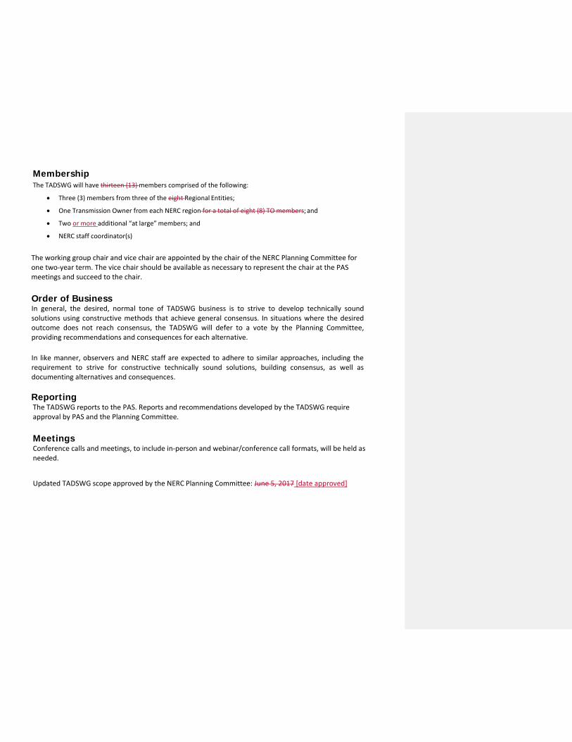
Membership The TADSWG will have thirteen (13) members comprised of the following:
• Three (3) members from three of the eight Regional Entities;
• One Transmission Owner from each NERC region for a total of eight (8) TO members; and
• Two or more additional “at large” members; and
• NERC staff coordinator(s)
The working group chair and vice chair are appointed by the chair of the NERC Planning Committee for one two-year term. The vice chair should be available as necessary to represent the chair at the PAS meetings and succeed to the chair.
Order of Business In general, the desired, normal tone of TADSWG business is to strive to develop technically sound solutions using constructive methods that achieve general consensus. In situations where the desired outcome does not reach consensus, the TADSWG will defer to a vote by the Planning Committee, providing recommendations and consequences for each alternative.
In like manner, observers and NERC staff are expected to adhere to similar approaches, including the requirement to strive for constructive technically sound solutions, building consensus, as well as documenting alternatives and consequences.
Reporting The TADSWG reports to the PAS. Reports and recommendations developed by the TADSWG require approval by PAS and the Planning Committee. Meetings Conference calls and meetings, to include in-person and webinar/conference call formats, will be held as needed.
Updated TADSWG scope approved by the NERC Planning Committee: June 5, 2017 [date approved]
NERC Planning Committee Work Plan 2018 – Q3 August 2018
NERC Planning Committee Work Plan 2
Table of Contents PC Meeting Schedule ..................................................................................................................................................3
PC Subgroup Organization Chart ................................................................................................................................4
PC Subgroup Work Plan ..............................................................................................................................................5
Reliability Assessment Subcommittee (RAS) ..........................................................................................................5
Probabilistic Assessment Working Group (PAWG) .............................................................................................5
Performance Analysis Subcommittee (PAS) ...........................................................................................................6
Generating Availability Data System Working Group (GADSWG) ......................................................................6
Transmission Availability Data System Working Group (TADSWG) ...................................................................7
Demand Response Availability Data System Working Group (DADSWG) ..........................................................7
Misoperations Information Data Analysis System Working Group (MIDASWG) ...............................................7
System Analysis & Modeling Subcommittee (SAMS) .............................................................................................8
Load Modeling Task Force (LMTF) ......................................................................................................................9
Power Plant Modeling & Verification Task Force (PPMVTF) ........................................................................... 10
System Protection & Control Subcommittee (SPCS) ........................................................................................... 11
Synchronized Measurements Subcommittee (SMS) ........................................................................................... 11
Geomagnetic Disturbance Task Force (GMDTF) ................................................................................................. 11
Methods for Establishing IROLs Task Force (MEITF) ........................................................................................... 12
Inverter-Based Resource Performance Task Force (IRPTF) ................................................................................. 13
NERC Planning Committee Work Plan 3
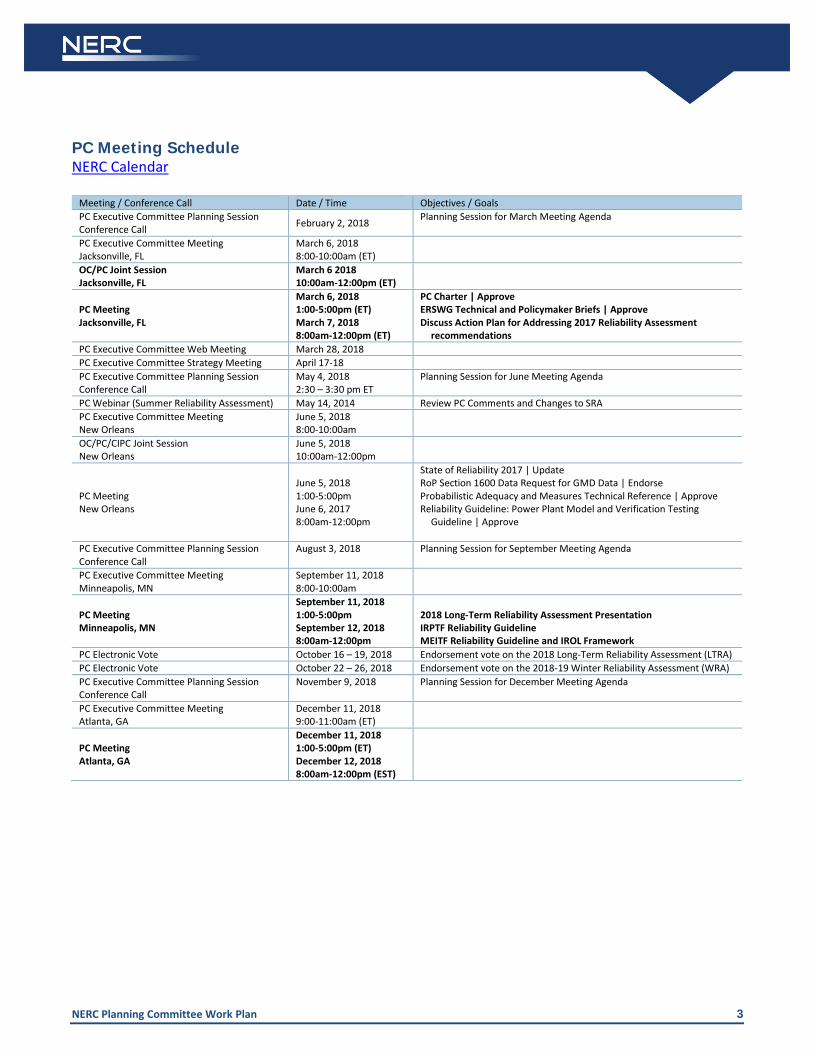
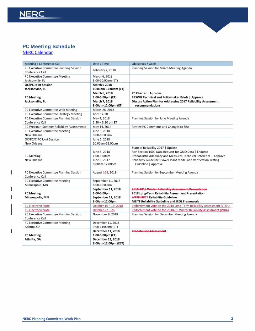
PC Meeting Schedule NERC Calendar
Meeting / Conference Call Date / Time Objectives / Goals PC Executive Committee Planning Session Conference Call February 2, 2018 Planning Session for March Meeting Agenda
PC Executive Committee Meeting Jacksonville, FL
March 6, 2018 8:00-10:00am (ET)
OC/PC Joint Session Jacksonville, FL
March 6 2018 10:00am-12:00pm (ET)
PC Meeting Jacksonville, FL
March 6, 2018 1:00-5:00pm (ET) March 7, 2018 8:00am-12:00pm (ET)
PC Charter | Approve ERSWG Technical and Policymaker Briefs | Approve Discuss Action Plan for Addressing 2017 Reliability Assessment
recommendations PC Executive Committee Web Meeting March 28, 2018 PC Executive Committee Strategy Meeting April 17-18 PC Executive Committee Planning Session Conference Call
May 4, 2018 2:30 – 3:30 pm ET
Planning Session for June Meeting Agenda
PC Webinar (Summer Reliability Assessment) May 14, 2014 Review PC Comments and Changes to SRA PC Executive Committee Meeting New Orleans
June 5, 2018 8:00-10:00am
OC/PC/CIPC Joint Session New Orleans
June 5, 2018 10:00am-12:00pm
PC Meeting New Orleans
June 5, 2018 1:00-5:00pm June 6, 2017 8:00am-12:00pm
State of Reliability 2017 | Update RoP Section 1600 Data Request for GMD Data | Endorse Probabilistic Adequacy and Measures Technical Reference | Approve Reliability Guideline: Power Plant Model and Verification Testing
Guideline | Approve
PC Executive Committee Planning Session Conference Call
August 3, 2018
Planning Session for September Meeting Agenda
PC Executive Committee Meeting Minneapolis, MN
September 11, 2018 8:00-10:00am
PC Meeting Minneapolis, MN
September 11, 2018 1:00-5:00pm September 12, 2018 8:00am-12:00pm
2018 Long-Term Reliability Assessment Presentation IRPTF Reliability Guideline MEITF Reliability Guideline and IROL Framework
PC Electronic Vote October 16 – 19, 2018 Endorsement vote on the 2018 Long-Term Reliability Assessment (LTRA) PC Electronic Vote October 22 – 26, 2018 Endorsement vote on the 2018-19 Winter Reliability Assessment (WRA) PC Executive Committee Planning Session Conference Call
November 9, 2018
Planning Session for December Meeting Agenda
PC Executive Committee Meeting Atlanta, GA
December 11, 2018 9:00-11:00am (ET)
PC Meeting Atlanta, GA
December 11, 2018 1:00-5:00pm (ET) December 12, 2018 8:00am-12:00pm (EST)
NERC Planning Committee Work Plan 4
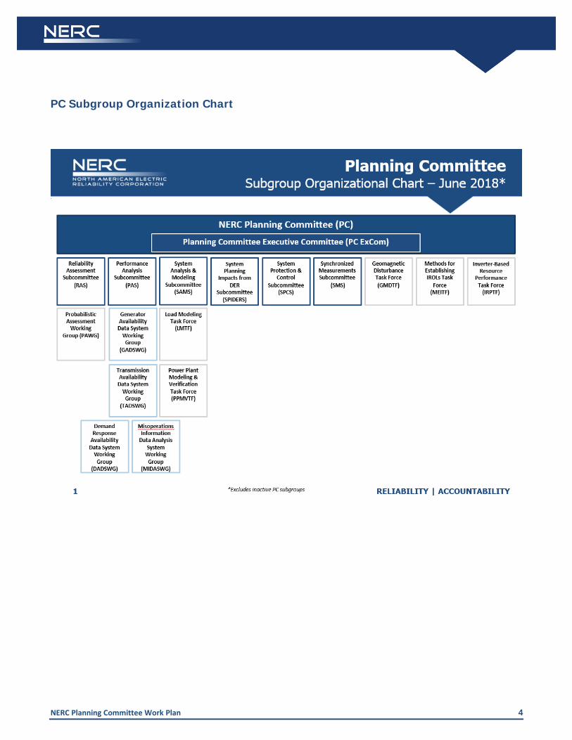
PC Subgroup Organization Chart
NERC Planning Committee Work Plan 5
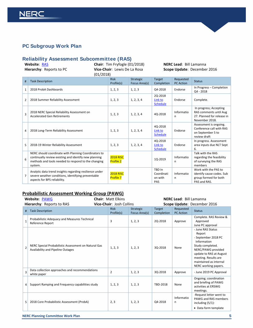
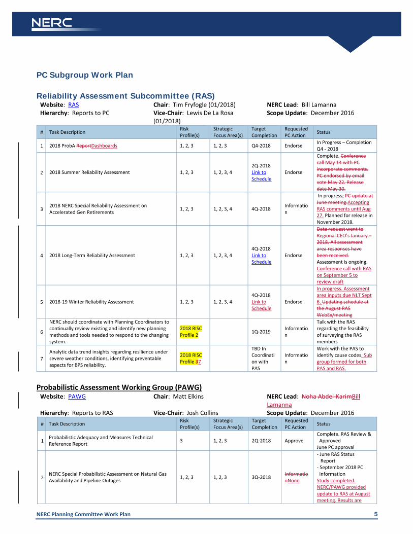
PC Subgroup Work Plan Reliability Assessment Subcommittee (RAS)
Website: RAS Chair: Tim Fryfogle (01/2018) NERC Lead: Bill Lamanna Hierarchy: Reports to PC Vice-Chair: Lewis De La Rosa
(01/2018) Scope Update: December 2016
# Task Description Risk Profile(s)
Strategic Focus Area(s)
Target Completion
Requested PC Action Status
1 2018 ProbA Dashboards 1, 2, 3 1, 2, 3 Q4-2018 Endorse In Progress – Completion Q4 - 2018
2 2018 Summer Reliability Assessment 1, 2, 3 1, 2, 3, 4 2Q-2018 Link to Schedule
Endorse Complete.
3 2018 NERC Special Reliability Assessment on Accelerated Gen Retirements 1, 2, 3 1, 2, 3, 4 4Q-2018 Informatio
n
In progress; Accepting RAS comments until Aug 27. Planned for release in November 2018.
4 2018 Long-Term Reliability Assessment 1, 2, 3 1, 2, 3, 4 4Q-2018 Link to Schedule
Endorse
Assessment is ongoing. Conference call with RAS on September 5 to review draft
5 2018-19 Winter Reliability Assessment 1, 2, 3 1, 2, 3, 4 4Q-2018 Link to Schedule
Endorse In progress. Assessment area inputs due NLT Sept 6.
6
NERC should coordinate with Planning Coordinators to continually review existing and identify new planning methods and tools needed to respond to the changing system.
2018 RISC Profile 2 1Q-2019 Informatio
n
Talk with the RAS regarding the feasibility of surveying the RAS members
7 Analytic data trend insights regarding resilience under severe weather conditions, identifying preventable aspects for BPS reliability.
2018 RISC Profile 7
TBD In Coordination with PAS
Information
Work with the PAS to identify cause codes. Sub group formed for both PAS and RAS.
Probabilistic Assessment Working Group (PAWG)
Website: PAWG Chair: Matt Elkins NERC Lead: Bill Lamanna Hierarchy: Reports to RAS Vice-Chair: Josh Collins Scope Update: December 2016
# Task Description Risk Profile(s)
Strategic Focus Area(s)
Target Completion
Requested PC Action Status
1 Probabilistic Adequacy and Measures Technical Reference Report 3 1, 2, 3 2Q-2018 Approve
Complete. RAS Review & Approved June PC approval
2 NERC Special Probabilistic Assessment on Natural Gas Availability and Pipeline Outages 1, 2, 3 1, 2, 3 3Q-2018 None
- June RAS Status Report - September 2018 PC Information Study completed. NERC/PAWG provided update to RAS at August meeting. Results are maintained as internal NERC working papers.
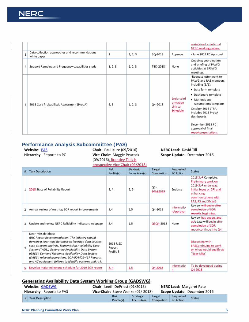
3 Data collection approaches and recommendations white paper 2 1, 2, 3 3Q-2018 Approve - June 2019 PC Approval
4 Support Ramping and Frequency capabilities study 1, 2, 3 1, 2, 3 TBD-2018 None
Ongoing; coordination and briefing of PAWG activities at ERSWG meetings.
5 2018 Core Probabilistic Assessment (ProbA) 2, 3 1, 2, 3 Q4-2018 Information
-Request letter went to PAWG and RAS members including (5/1): • Data form template
NERC Planning Committee Work Plan 6
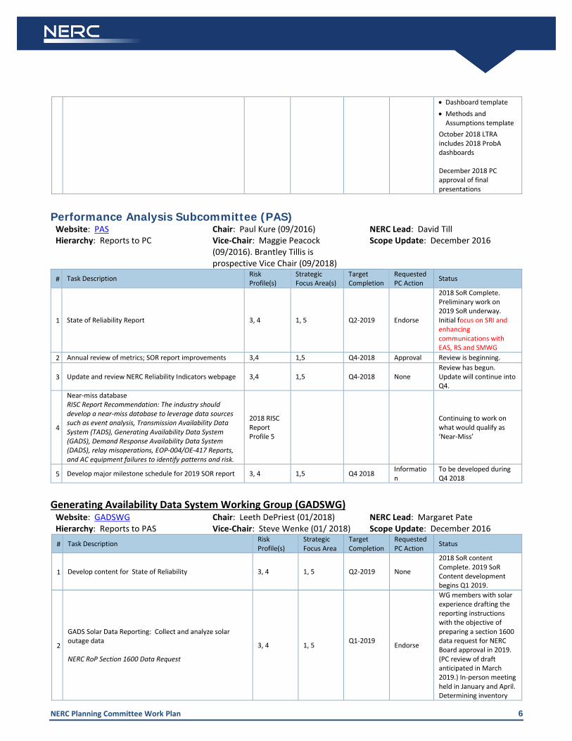
• Dashboard template • Methods and
Assumptions template October 2018 LTRA includes 2018 ProbA dashboards December 2018 PC approval of final presentations
Performance Analysis Subcommittee (PAS)
Website: PAS Chair: Paul Kure (09/2016) NERC Lead: David Till Hierarchy: Reports to PC Vice-Chair: Maggie Peacock
(09/2016). Brantley Tillis is prospective Vice Chair (09/2018)
Scope Update: December 2016
# Task Description Risk Profile(s)
Strategic Focus Area(s)
Target Completion
Requested PC Action Status
1 State of Reliability Report 3, 4 1, 5 Q2-2019 Endorse
2018 SoR Complete. Preliminary work on 2019 SoR underway. Initial focus on SRI and enhancing communications with EAS, RS and SMWG
2 Annual review of metrics; SOR report improvements 3,4 1,5 Q4-2018 Approval Review is beginning.
3 Update and review NERC Reliability Indicators webpage 3,4 1,5 Q4-2018 None Review has begun. Update will continue into Q4.
4
Near-miss database RISC Report Recommendation: The industry should develop a near-miss database to leverage data sources such as event analysis, Transmission Availability Data System (TADS), Generating Availability Data System (GADS), Demand Response Availability Data System (DADS), relay misoperations, EOP-004/OE-417 Reports, and AC equipment failures to identify patterns and risk.
2018 RISC Report Profile 5
Continuing to work on what would qualify as ‘Near-Miss’
5 Develop major milestone schedule for 2019 SOR report 3, 4 1,5 Q4 2018 Information
To be developed during Q4 2018
Generating Availability Data System Working Group (GADSWG)
Website: GADSWG Chair: Leeth DePriest (01/2018) NERC Lead: Margaret Pate Hierarchy: Reports to PAS Vice-Chair: Steve Wenke (01/ 2018) Scope Update: December 2016
# Task Description Risk Profile(s)
Strategic Focus Area
Target Completion
Requested PC Action Status
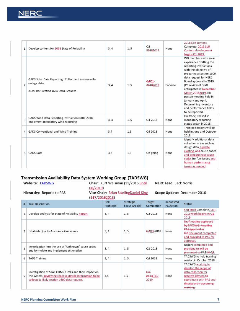
1 Develop content for State of Reliability 3, 4 1, 5 Q2-2019 None
2018 SoR content Complete. 2019 SoR Content development begins Q1 2019.
2
GADS Solar Data Reporting: Collect and analyze solar outage data NERC RoP Section 1600 Data Request
3, 4 1, 5 Q1-2019 Endorse
WG members with solar experience drafting the reporting instructions with the objective of preparing a section 1600 data request for NERC Board approval in 2019. (PC review of draft anticipated in March 2019.) In-person meeting held in January and April. Determining inventory
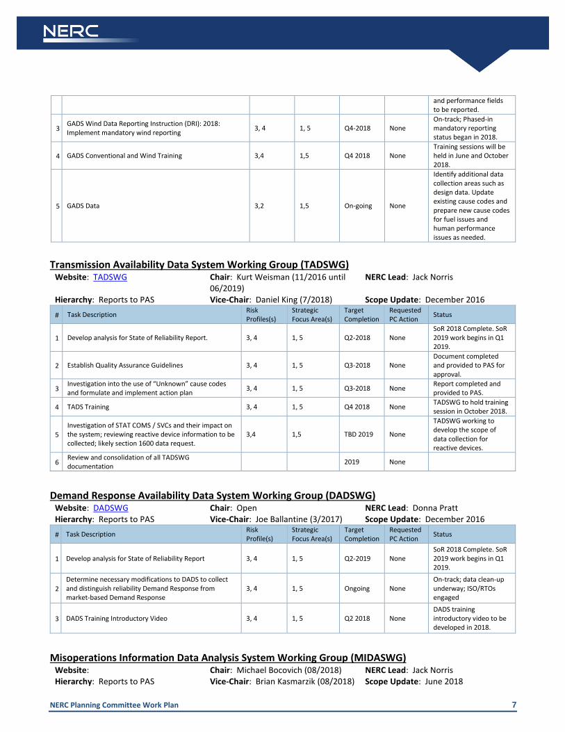
NERC Planning Committee Work Plan 7
and performance fields to be reported.
3 GADS Wind Data Reporting Instruction (DRI): 2018: Implement mandatory wind reporting 3, 4 1, 5 Q4-2018 None
On-track; Phased-in mandatory reporting status began in 2018.
4 GADS Conventional and Wind Training 3,4 1,5 Q4 2018 None Training sessions will be held in June and October 2018.
5 GADS Data 3,2 1,5 On-going None
Identify additional data collection areas such as design data. Update existing cause codes and prepare new cause codes for fuel issues and human performance issues as needed.
Transmission Availability Data System Working Group (TADSWG)
Website: TADSWG Chair: Kurt Weisman (11/2016 until 06/2019)
NERC Lead: Jack Norris
Hierarchy: Reports to PAS Vice-Chair: Daniel King (7/2018) Scope Update: December 2016
# Task Description Risk Profiles(s)
Strategic Focus Area(s)
Target Completion
Requested PC Action Status
1 Develop analysis for State of Reliability Report. 3, 4 1, 5 Q2-2018 None SoR 2018 Complete. SoR 2019 work begins in Q1 2019.
2 Establish Quality Assurance Guidelines 3, 4 1, 5 Q3-2018 None Document completed and provided to PAS for approval.
3 Investigation into the use of “Unknown” cause codes and formulate and implement action plan 3, 4 1, 5 Q3-2018 None Report completed and
provided to PAS.
4 TADS Training 3, 4 1, 5 Q4 2018 None TADSWG to hold training session in October 2018.
5 Investigation of STAT COMS / SVCs and their impact on the system; reviewing reactive device information to be collected; likely section 1600 data request.
3,4 1,5 TBD 2019 None
TADSWG working to develop the scope of data collection for reactive devices.
6 Review and consolidation of all TADSWG documentation 2019 None
Demand Response Availability Data System Working Group (DADSWG)
Website: DADSWG Chair: Open NERC Lead: Donna Pratt Hierarchy: Reports to PAS Vice-Chair: Joe Ballantine (3/2017) Scope Update: December 2016
# Task Description Risk Profile(s)
Strategic Focus Area(s)
Target Completion
Requested PC Action Status
1 Develop analysis for State of Reliability Report 3, 4 1, 5 Q2-2019 None SoR 2018 Complete. SoR 2019 work begins in Q1 2019.
2 Determine necessary modifications to DADS to collect and distinguish reliability Demand Response from market-based Demand Response
3, 4 1, 5 Ongoing None On-track; data clean-up underway; ISO/RTOs engaged
3 DADS Training Introductory Video 3, 4 1, 5 Q2 2018 None DADS training introductory video to be developed in 2018.
Misoperations Information Data Analysis System Working Group (MIDASWG)
Website: Chair: Michael Bocovich (08/2018) NERC Lead: Jack Norris Hierarchy: Reports to PAS Vice-Chair: Brian Kasmarzik (08/2018) Scope Update: June 2018
NERC Planning Committee Work Plan 8
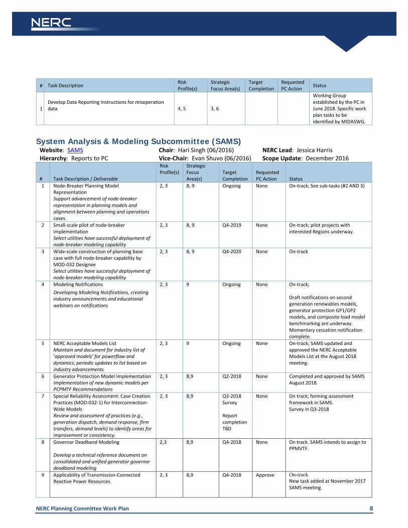
# Task Description Risk
Profile(s) Strategic Focus Area(s)
Target Completion
Requested PC Action Status
1 Develop Data Reporting Instructions for misoperation data
4, 5 3, 6
Working Group established by the PC in June 2018. Specific work plan tasks to be identified by MIDASWG.
System Analysis & Modeling Subcommittee (SAMS)
Website: SAMS Chair: Hari Singh (06/2016) NERC Lead: Jessica Harris Hierarchy: Reports to PC Vice-Chair: Evan Shuvo (06/2016) Scope Update: December 2016
# Task Description / Deliverable
Risk Profile(s)
Strategic Focus Area(s)
Target Completion
Requested PC Action Status
1 Node-Breaker Planning Model Representation Support advancement of node-breaker representation in planning models and alignment between planning and operations cases.
2, 3 8, 9 Ongoing None On-track; See sub-tasks (#2 AND 3)
2 Small-scale pilot of node-breaker implementation Select utilities have successful deployment of node-breaker modeling capability
2, 3 8, 9 Q4-2019 None On-track; pilot projects with interested Regions underway.
3 Wide-scale construction of planning base case with full node-breaker capability by MOD-032 Designee Select utilities have successful deployment of node-breaker modeling capability
2, 3 8, 9 Q4-2020 None On-track
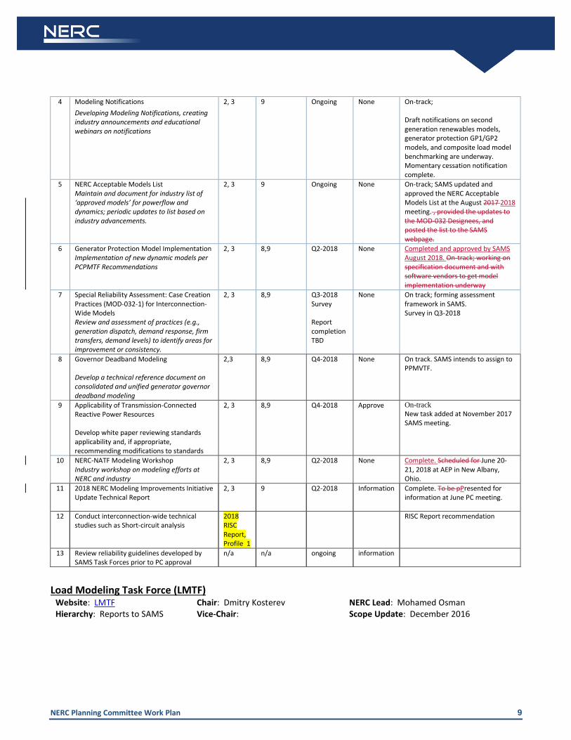
4 Modeling Notifications Developing Modeling Notifications, creating industry announcements and educational webinars on notifications
2, 3 9 Ongoing None On-track; Draft notifications on second generation renewables models, generator protection GP1/GP2 models, and composite load model benchmarking are underway. Momentary cessation notification complete.
5 NERC Acceptable Models List Maintain and document for industry list of ‘approved models’ for powerflow and dynamics; periodic updates to list based on industry advancements.
2, 3 9 Ongoing None On-track; SAMS updated and approved the NERC Acceptable Models List at the August 2018 meeting.
6 Generator Protection Model Implementation Implementation of new dynamic models per PCPMTF Recommendations
2, 3 8,9 Q2-2018 None Completed and approved by SAMS August 2018.
7 Special Reliability Assessment: Case Creation Practices (MOD-032-1) for Interconnection-Wide Models Review and assessment of practices (e.g., generation dispatch, demand response, firm transfers, demand levels) to identify areas for improvement or consistency.
2, 3 8,9 Q3-2018 Survey Report completion TBD
None On track; forming assessment framework in SAMS. Survey in Q3-2018
8 Governor Deadband Modeling Develop a technical reference document on consolidated and unified generator governor deadband modeling
2,3 8,9 Q4-2018 None On track. SAMS intends to assign to PPMVTF.
9 Applicability of Transmission-Connected Reactive Power Resources
2, 3 8,9 Q4-2018 Approve On-track New task added at November 2017 SAMS meeting.

NERC Planning Committee Work Plan 9
Develop white paper reviewing standards applicability and, if appropriate, recommending modifications to standards
10 NERC-NATF Modeling Workshop Industry workshop on modeling efforts at NERC and industry
2, 3 8,9 Q2-2018 None Complete. June 20-21, 2018 at AEP in New Albany, Ohio.
11 2018 NERC Modeling Improvements Initiative Update Technical Report
2, 3 9 Q2-2018 Information Complete. Presented for information at June PC meeting.
12 Conduct interconnection-wide technical studies such as Short-circuit analysis
2018 RISC Report, Profile 1
RISC Report recommendation
13 Review reliability guidelines developed by SAMS Task Forces prior to PC approval
n/a n/a ongoing information
Load Modeling Task Force (LMTF)
Website: LMTF Chair: Dmitry Kosterev NERC Lead: Mohamed Osman Hierarchy: Reports to SAMS Vice-Chair: Scope Update: December 2016
# Task Description / Deliverables Risk Profile(s)
Strategic Focus Area(s)
Target Completion
Requested PC Action Status
1 Load Model (Software) Benchmarking 2, 3 9 Ongoing None
Phase 1 complete--all major software vendors benchmarked composite load model successfully; Additional work on track: beginning implementation and benchmarking of composite load model with DER component and single phase motors.
2
Robust (Default) Data Sets Default datasets to support utilities seeking guidance on reasonable load model parameters (e.g., starting point or no other data available)
2, 3 9 Q2-2018 None
On-track; LMTF will approve new default data set for Phase 2 (single phase motor stalling) parameters. Two data sets were posted, 3rd data set with relaxed protection setting is under development
3 System Impact Assessment Utility members sharing experience of load modeling and studies; user forum for sharing lessons learned.
2, 3 8, 9 Ongoing None On-track; ongoing information sharing.
4
Dynamic Load Modeling in Real-Time Stability Analysis Assessment of industry practices for use of dynamic load models for real-time or operations planning studies
2, 3 8, 9 Q4-2018 None
Delayed due to higher priority topics; resetting completion to Q4 2018. Survey released to LMTF members; follow-up and compilation is next step.
5
Progressive Protection System Modeling Testing and studying progressive tripping, reconnection, and stalling modeling approach for improved model performance
2, 3 9 Q4-2018 None
Require modular implementation first (task 10). longer-term goal; beta testing being performed by multiple software vendors.
6 Improved Single-Phase Motor Model 2, 3 9 Q4-2018 None
On-track, make model available to software developer for implementation (task 8 is a prerequisite)

NERC Planning Committee Work Plan 10
7 Improved Three-Phase Motor Model 2, 3 9 Q4-2018 None
On-track, make model available to software developer for implementation (task 8 is a prerequisite)
8 Efficient Data Format & Model Management New data format to modularize dynamic load models 2, 3 9 Q4-2018 None
On-track; beta testing being performed by multiple software vendors. PSLF and Powerworld already capable, PSS/E will need major version release (Verion 35)
9
Modeling Notifications: Composite Load Model Benchmarking. Develop composite load model benchmarking notification to share with industry the completion and usability of the models across all major software platforms.
2, 3 9 Q3-2018 None On-Track
10 Load Composition Analysis (e.g, Buildings, end uses) 2,3 9 On-going None On-track; ongoing information sharing.
11 Power Electronics Load, adjustable drive (VFD, ECM) electric vehicle charger models 2,3 9 On-going None On-track; ongoing
information sharing.
12 Load Model Data Management Tool 2,3 9 On-going None On-track; ongoing information sharing.
Power Plant Modeling & Verification Task Force (PPMVTF)
Website: PPMVTF Chair: Shawn Patterson NERC Lead: Ryan Quint Hierarchy: Reports to SAMS Vice-Chair: Scope Update: May 2016 # Task Description / Deliverable Risk
Profile(s) Strategic Focus Area(s)
Target Completion
Requested PC Action Status
Synchronous Generation Fleet
1
Reliability Guideline: Power Plant Model Verification for Synchronous Machines Reliability Guideline on power plant model verification and testing
2, 3, 4 8,9 Q2 2018 Approve Complete. PC Approved June 2018.
2 Power Plant Model Review Review NERC acceptable list of models for power plants, provide guidance to development of list
2, 3, 4 8,9 Ongoing No Ongoing
3 Plant Auxiliary Modeling Practices Develop modeling practices for possible tripping of plant auxiliary equipment
2, 3, 4 8,9 N/A None Cancelled by PPMVTF members.
4
Reliability Guideline: MOD-032-1 Generator Data Requests Develop technical guidance material for MOD-032-1 data requests and sharing; in response to NAGF letter seeking guidance
2,3 8,9 Q1 2019 Approve On track
Inverter-Based (Renewable) Generation Fleet
5
Reliability Guideline: Power Plant Model Verification for Inverter-Based Resources Reliability Guideline on power plant model verification for inverter-based resources
2, 3, 4 8,9 Q4 2018 Approve On-track; Seeking final approval at September PC meeting
6
Inverter-Based Resource Short Circuit Representation Coordinate with IEEE PSRC WG C24 focused on short circuit modeling improvements for inverter-based resources
2, 3, 4 8,9 Ongoing None Ongoing
NERC Planning Committee Work Plan 11
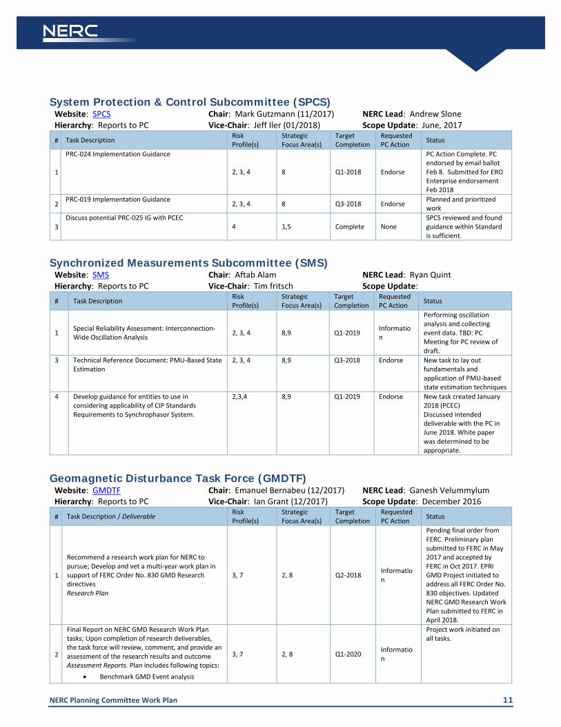
System Protection & Control Subcommittee (SPCS) Website: SPCS Chair: Mark Gutzmann (11/2017) NERC Lead: Andrew Slone Hierarchy: Reports to PC Vice-Chair: Jeff Iler (01/2018) Scope Update: June, 2017
# Task Description Risk Profile(s)
Strategic Focus Area(s)
Target Completion
Requested PC Action Status
1
PRC-024 Implementation Guidance
2, 3, 4 8 Q1-2018 Endorse
PC Action Complete. PC endorsed by email ballot Feb 8. Submitted for ERO Enterprise endorsement Feb 2018
2 PRC-019 Implementation Guidance 2, 3, 4 8 Q3-2018 Endorse Planned and prioritized
work
3 Discuss potential PRC-025 IG with PCEC
4 1,5 Complete None SPCS reviewed and found guidance within Standard is sufficient.
Synchronized Measurements Subcommittee (SMS)
Website: SMS Chair: Aftab Alam NERC Lead: Ryan Quint Hierarchy: Reports to PC Vice-Chair: Tim fritsch Scope Update: # Task Description Risk
Profile(s) Strategic Focus Area(s)
Target Completion
Requested PC Action Status
1 Special Reliability Assessment: Interconnection-Wide Oscillation Analysis 2, 3, 4 8,9 Q1-2019 Informatio
n
Performing oscillation analysis and collecting event data. TBD: PC Meeting for PC review of draft.
3 Technical Reference Document: PMU-Based State Estimation
2, 3, 4 8,9 Q3-2018 Endorse New task to lay out fundamentals and application of PMU-based state estimation techniques
4 Develop guidance for entities to use in considering applicability of CIP Standards Requirements to Synchrophasor System.
2,3,4 8,9 Q1-2019 Endorse New task created January 2018 (PCEC) Discussed intended deliverable with the PC in June 2018. White paper was determined to be appropriate.
Geomagnetic Disturbance Task Force (GMDTF) Website: GMDTF Chair: Emanuel Bernabeu (12/2017) NERC Lead: Ganesh Velummylum Hierarchy: Reports to PC Vice-Chair: Ian Grant (12/2017) Scope Update: December 2016
# Task Description / Deliverable Risk Profile(s)
Strategic Focus Area(s)
Target Completion
Requested PC Action Status
1
Recommend a research work plan for NERC to pursue; Develop and vet a multi-year work plan in support of FERC Order No. 830 GMD Research directives Research Plan
3, 7 2, 8 Q2-2018 Information
Pending final order from FERC. Preliminary plan submitted to FERC in May 2017 and accepted by FERC in Oct 2017. EPRI GMD Project initiated to address all FERC Order No. 830 objectives. Updated NERC GMD Research Work Plan submitted to FERC in April 2018.
2
Final Report on NERC GMD Research Work Plan tasks; Upon completion of research deliverables, the task force will review, comment, and provide an assessment of the research results and outcome Assessment Reports. Plan includes following topics:
• Benchmark GMD Event analysis
3, 7 2, 8 Q1-2020 Information
Project work initiated on all tasks.

NERC Planning Committee Work Plan 12
• Latitude scaling analysis • Earth conductivity model
review/enhancement • Transformer thermal modeling and
vulnerability assessment • GMD-related harmonics vulnerability
assessment • Transformer harmonic vibration impact
assessment
3
Data Request; Develop an ROP Section 1600 Data Request for the collection of existing (data since 2013) and new GIC and magnetometer data that can be made available to public Section 1600 Data Request to PC and OC
3, 7 2, 8 Q2-2018 Endorse Complete. NERC Board authorized data collection August 16, 2018.
4
Develop a Data Reporting Instruction for entities to collect and report GIC and magnetometer data as specified in the ROP Section 1600 Data Request
3, 7 2, 8 Q1-2019 Approve
NERC Staff and GMDTF team began work on draft DRI in August following completion of NERC Board action on section 1600 data request
5
GIC Monitoring and Magnetometer Data Collection Assessment; recommend how NERC should assess and report on the degree to which industry is following Section 1600 Data Request and guidance for GIC monitoring. (Guidance for GIC monitoring is was developed by the GMD Standards Drafting Team as part of revisions to TPL-007). (Ref P. 88) Plan for reviewing GIC data
3, 7 2, 8 Q1-2019 (process)
Information
Process will be included in the DRI.
6
Transformer Thermal Model Tool; Develop and make available a tool for transformer thermal assessment. Tool will provide transformer thermal response to input GIC data, given a transformer thermal model Publicly available tool
3, 7 2, 8 Q2-2018 Information
Complete. Software is available for download from EPRI at no charge. (Product ID 3002014059)
7
Assess industry needs for capabilities to perform GMD-related harmonics analysis to support implementation of TPL-007 and identify best practices. Deliverable TBD; consider Implementation Guidance
3, 7 2, 8 Q4-2018 TBD
8
Analyze data from GMD events collected under the GMD Data Request and other necessary information to further understand GIC effects on BES facilities. Summarize observations, including observations on GIC modeling.
2018 RISC Profile 7 Q4-2020 Informatio
n
Activity is from 2018 RISC Report. Requires implementation of the Sect 1600 data request.
Methods for Establishing IROLs Task Force (MEITF) Website: MEITF PC Liaison: Hari Singh NERC Lead: Ryan Quint Hierarchy: Reports to PC and OC PC Liaison: Wayne Guttormson Scope Update: December 2016 # Task Description Risk
Profile(s) Strategic Focus Area(s)
Target Completion
Requested PC Action Status
1 Reliability Guideline: Methods for Establishing IROLs Reliability Guideline 2, 3, 4 8, 9 Q3-2018 Approve Seeking PC approval in
September 2018.
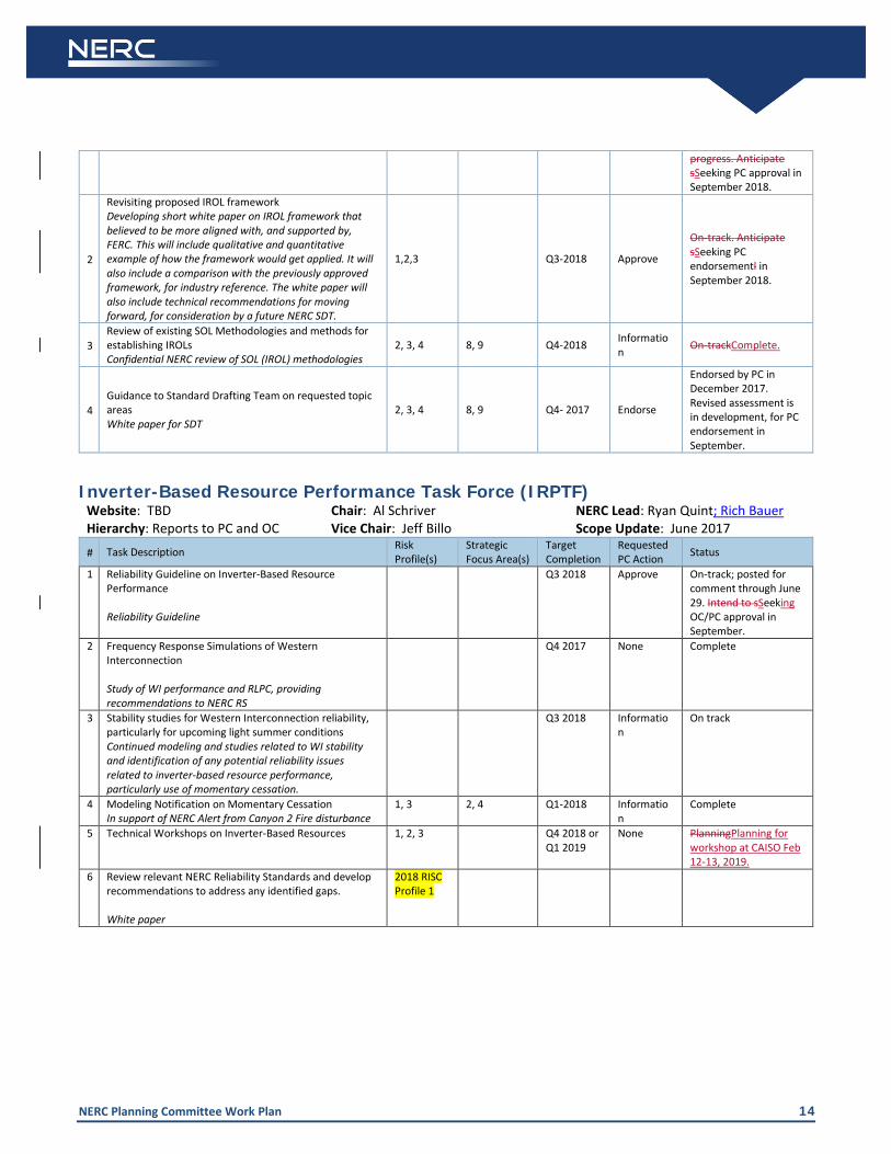
2
Revisiting proposed IROL framework Developing short white paper on IROL framework that believed to be more aligned with, and supported by, FERC. This will include qualitative and quantitative example of how the framework would get applied. It will also include a comparison with the previously approved framework, for industry reference. The white paper will
1,2,3 Q3-2018 Approve Seeking PC endorsement in September 2018.

NERC Planning Committee Work Plan 13
also include technical recommendations for moving forward, for consideration by a future NERC SDT.
3 Review of existing SOL Methodologies and methods for establishing IROLs Confidential NERC review of SOL (IROL) methodologies
2, 3, 4 8, 9 Q4-2018 Information Complete.
4 Guidance to Standard Drafting Team on requested topic areas White paper for SDT
2, 3, 4 8, 9 Q4- 2017 Endorse
Endorsed by PC in December 2017. Revised assessment is in development, for PC endorsement in September.
Inverter-Based Resource Performance Task Force (IRPTF)
Website: TBD Chair: Al Schriver NERC Lead: Ryan Quint; Rich Bauer Hierarchy: Reports to PC and OC Vice Chair: Jeff Billo Scope Update: June 2017 # Task Description Risk
Profile(s) Strategic Focus Area(s)
Target Completion
Requested PC Action Status
1 Reliability Guideline on Inverter-Based Resource Performance Reliability Guideline
Q3 2018 Approve On-track; posted for comment through June 29. Seeking OC/PC approval in September.
2 Frequency Response Simulations of Western Interconnection Study of WI performance and RLPC, providing recommendations to NERC RS
Q4 2017 None Complete
3 Stability studies for Western Interconnection reliability, particularly for upcoming light summer conditions Continued modeling and studies related to WI stability and identification of any potential reliability issues related to inverter-based resource performance, particularly use of momentary cessation.
Q3 2018 Information
On track
4 Modeling Notification on Momentary Cessation In support of NERC Alert from Canyon 2 Fire disturbance
1, 3 2, 4 Q1-2018 Information
Complete
5 Technical Workshops on Inverter-Based Resources 1, 2, 3 Q4 2018 or Q1 2019
None Planning for workshop at CAISO Feb 12-13, 2019.
6 Review relevant NERC Reliability Standards and develop recommendations to address any identified gaps. White paper
2018 RISC Profile 1
NERC Planning Committee Work Plan 2018 – Q3 July August 2018
NERC Planning Committee Work Plan 2
Table of Contents PC Meeting Schedule ..................................................................................................................................................3
PC Subgroup Organization Chart ................................................................................................................................4
PC Subgroup Work Plan ..............................................................................................................................................5
Reliability Assessment Subcommittee (RAS) ..........................................................................................................5
Probabilistic Assessment Working Group (PAWG) .............................................................................................5
Performance Analysis Subcommittee (PAS) ...........................................................................................................6
Generating Availability Data System Working Group (GADSWG) ......................................................................6
Transmission Availability Data System Working Group (TADSWG) ...................................................................7
Demand Response Availability Data System Working Group (DADSWG) ..........................................................8
System Analysis & Modeling Subcommittee (SAMS) .............................................................................................8
Load Modeling Task Force (LMTF) ......................................................................................................................9
Power Plant Modeling & Verification Task Force (PPMVTF) ........................................................................... 11
System Protection & Control Subcommittee (SPCS) ........................................................................................... 12
Synchronized Measurements Subcommittee (SMS) ........................................................................................... 12
Geomagnetic Disturbance Task Force (GMDTF) ................................................................................................. 12
Essential Reliability Services Working Group (ERSWG) ........................................... Error! Bookmark not defined.
Methods for Establishing IROLs Task Force (MEITF) ........................................................................................... 13
Inverter-Based Resource Performance Task Force (IRPTF) ................................................................................. 14
NERC Planning Committee Work Plan 3
PC Meeting Schedule NERC Calendar
Meeting / Conference Call Date / Time Objectives / Goals PC Executive Committee Planning Session Conference Call February 2, 2018 Planning Session for March Meeting Agenda
PC Executive Committee Meeting Jacksonville, FL
March 6, 2018 8:00-10:00am (ET)
OC/PC Joint Session Jacksonville, FL
March 6 2018 10:00am-12:00pm (ET)
PC Meeting Jacksonville, FL
March 6, 2018 1:00-5:00pm (ET) March 7, 2018 8:00am-12:00pm (ET)
PC Charter | Approve ERSWG Technical and Policymaker Briefs | Approve Discuss Action Plan for Addressing 2017 Reliability Assessment
recommendations PC Executive Committee Web Meeting March 28, 2018 PC Executive Committee Strategy Meeting April 17-18 PC Executive Committee Planning Session Conference Call
May 4, 2018 2:30 – 3:30 pm ET
Planning Session for June Meeting Agenda
PC Webinar (Summer Reliability Assessment) May 14, 2014 Review PC Comments and Changes to SRA PC Executive Committee Meeting New Orleans
June 5, 2018 8:00-10:00am
OC/PC/CIPC Joint Session New Orleans
June 5, 2018 10:00am-12:00pm
PC Meeting New Orleans
June 5, 2018 1:00-5:00pm June 6, 2017 8:00am-12:00pm
State of Reliability 2017 | Update RoP Section 1600 Data Request for GMD Data | Endorse Probabilistic Adequacy and Measures Technical Reference | Approve Reliability Guideline: Power Plant Model and Verification Testing
Guideline | Approve
PC Executive Committee Planning Session Conference Call
August 103, 2018
Planning Session for September Meeting Agenda
PC Executive Committee Meeting Minneapolis, MN
September 11, 2018 8:00-10:00am
PC Meeting Minneapolis, MN
September 11, 2018 1:00-5:00pm September 12, 2018 8:00am-12:00pm
2018-2019 Winter Reliability Assessment Presentation 2018 Long-Term Reliability Assessment Presentation IVPTF IRPTF Reliability Guideline MEITF Reliability Guideline and IROL Framework
PC Electronic Vote October 16 – 19, 2018 Endorsement vote on the 2018 Long-Term Reliability Assessment (LTRA) PC Electronic Vote October 22 – 26 Endorsement vote on the 2018-19 Winter Reliability Assessment (WRA) PC Executive Committee Planning Session Conference Call
November 9, 2018
Planning Session for December Meeting Agenda
PC Executive Committee Meeting Atlanta, GA
December 11, 2018 9:00-11:00am (ET)
PC Meeting Atlanta, GA
December 11, 2018 1:00-5:00pm (ET) December 12, 2018 8:00am-12:00pm (EST)
Probabilistic Assessment

NERC Planning Committee Work Plan 4
PC Subgroup Organization Chart
NERC Planning Committee Work Plan 5
PC Subgroup Work Plan Reliability Assessment Subcommittee (RAS)
Website: RAS Chair: Tim Fryfogle (01/2018) NERC Lead: Bill Lamanna Hierarchy: Reports to PC Vice-Chair: Lewis De La Rosa
(01/2018) Scope Update: December 2016
# Task Description Risk Profile(s)
Strategic Focus Area(s)
Target Completion
Requested PC Action Status
1 2018 ProbA ReportDashboards 1, 2, 3 1, 2, 3 Q4-2018 Endorse In Progress – Completion Q4 - 2018
2 2018 Summer Reliability Assessment 1, 2, 3 1, 2, 3, 4 2Q-2018 Link to Schedule
Endorse
Complete. Conference call May 14 with PC incorporate comments. PC endorsed by email vote May 22. Release date May 30.
3 2018 NERC Special Reliability Assessment on Accelerated Gen Retirements 1, 2, 3 1, 2, 3, 4 4Q-2018 Informatio
n
In progress; PC update at June meeting.Accepting RAS comments until Aug 27. Planned for release in November 2018.
4 2018 Long-Term Reliability Assessment 1, 2, 3 1, 2, 3, 4 4Q-2018 Link to Schedule
Endorse
Data request went to Regional CEO’s January – 2018. All assessment area responses have been received. Assessment is ongoing. Conference call with RAS on September 5 to review draft
5 2018-19 Winter Reliability Assessment 1, 2, 3 1, 2, 3, 4 4Q-2018 Link to Schedule
Endorse
In progress. Assessment area inputs due NLT Sept 6. Updating schedule at the August RAS WebEx/meeting
6
NERC should coordinate with Planning Coordinators to continually review existing and identify new planning methods and tools needed to respond to the changing system.
2018 RISC Profile 2 1Q-2019 Informatio
n
Talk with the RAS regarding the feasibility of surveying the RAS members
7 Analytic data trend insights regarding resilience under severe weather conditions, identifying preventable aspects for BPS reliability.
2018 RISC Profile 37
TBD In Coordination with PAS
Information
Work with the PAS to identify cause codes. Sub group formed for both PAS and RAS.
Probabilistic Assessment Working Group (PAWG)
Website: PAWG Chair: Matt Elkins NERC Lead: Noha Abdel-KarimBill Lamanna
Hierarchy: Reports to RAS Vice-Chair: Josh Collins Scope Update: December 2016
# Task Description Risk Profile(s)
Strategic Focus Area(s)
Target Completion
Requested PC Action Status
1 Probabilistic Adequacy and Measures Technical Reference Report 3 1, 2, 3 2Q-2018 Approve
Complete. RAS Review & Approved June PC approval
2 NERC Special Probabilistic Assessment on Natural Gas Availability and Pipeline Outages 1, 2, 3 1, 2, 3 3Q-2018 Informatio
nNone
- June RAS Status Report - September 2018 PC Information Study completed. NERC/PAWG provided update to RAS at August meeting. Results are
NERC Planning Committee Work Plan 6
maintained as internal NERC working papers.
3 Data collection approaches and recommendations white paper 2 1, 2, 3 3Q-2018 Approve - June 2019 PC Approval
4 Support Ramping and Frequency capabilities study 1, 2, 3 1, 2, 3 TBD-2018 None
Ongoing; coordination and briefing of PAWG activities at ERSWG meetings.
5 2018 Core Probabilistic Assessment (ProbA) 2, 3 1, 2, 3 Q4-2018
EndorseInformation Link to Schedule
-Request letter went to PAWG and RAS members including (5/1): • Data form template • Dashboard template • Methods and
Assumptions template October 2018 LTRA includes 2018 ProbA dashboards December 2018 PC approval of final reportpresentations
Performance Analysis Subcommittee (PAS)
Website: PAS Chair: Paul Kure (09/2016) NERC Lead: David Till Hierarchy: Reports to PC Vice-Chair: Maggie Peacock
(09/2016). Brantley Tillis is prospective Vice Chair (09/2018)
Scope Update: December 2016
# Task Description Risk Profile(s)
Strategic Focus Area(s)
Target Completion
Requested PC Action Status
1 2018 State of Reliability Report 3, 4 1, 5 Q2-20182019 Endorse
2018 SoR Complete. Preliminary work on 2019 SoR underway. Initial focus on SRI and enhancing communications with EAS, RS and SMWG
2 Annual review of metrics; SOR report improvements 3,4 1,5 Q4-2018 InformationApproval
Review will begin after completion of SOR reportis beginning.
3 Update and review NERC Reliability Indicators webpage 3,4 1,5 Q3Q4-2018 None
Review has begun. and uUpdate will begin after completion of SOR reportcontinue into Q4.
4
Near-miss database RISC Report Recommendation: The industry should develop a near-miss database to leverage data sources such as event analysis, Transmission Availability Data System (TADS), Generating Availability Data System (GADS), Demand Response Availability Data System (DADS), relay misoperations, EOP-004/OE-417 Reports, and AC equipment failures to identify patterns and risk.
2018 RISC Report Profile 5
Discussing with EASContinuing to work on what would qualify as ‘Near-Miss’
5 Develop major milestone schedule for 2019 SOR report 3, 4 1,5 Q4 2018 Information
To be developed during Q4 2018
Generating Availability Data System Working Group (GADSWG)
Website: GADSWG Chair: Leeth DePriest (01/2018) NERC Lead: Margaret Pate Hierarchy: Reports to PAS Vice-Chair: Steve Wenke (01/ 2018) Scope Update: December 2016
# Task Description Risk Profile(s)
Strategic Focus Area
Target Completion
Requested PC Action Status
NERC Planning Committee Work Plan 7
1 Develop content for 2018 State of Reliability 3, 4 1, 5 Q2-20182019 None
2018 SoR content Complete. 2019 SoR Content development begins Q1 2019.
2
GADS Solar Data Reporting: Collect and analyze solar outage data NERC RoP Section 1600 Data Request
3, 4 1, 5 Q4Q1-20182019
Endorse
WG members with solar experience drafting the reporting instructions with the objective of preparing a section 1600 data request for NERC Board approval in 2019. (PC review of draft anticipated in December March 20182019.) In-person meeting held in January and April. Determining inventory and performance fields to be reported.
3 GADS Wind Data Reporting Instruction (DRI): 2018: Implement mandatory wind reporting 3, 4 1, 5 Q4-2018 None
On-track; Phased-in mandatory reporting status began in 2018.
4 GADS Conventional and Wind Training 3,4 1,5 Q4 2018 None Training sessions will be held in June and October 2018.
5 GADS Data 3,2 1,5 On-going None
Identify additional data collection areas such as design data. Update existing and cause codes and prepare new cause codes for fuel issues and human performance issues as needed.
Transmission Availability Data System Working Group (TADSWG)
Website: TADSWG Chair: Kurt Weisman (11/2016 until 06/2019)
NERC Lead: Jack Norris
Hierarchy: Reports to PAS Vice-Chair: Brian StarlingDaniel King (117/20162018)
Scope Update: December 2016
# Task Description Risk Profiles(s)
Strategic Focus Area(s)
Target Completion
Requested PC Action Status
1 Develop analysis for State of Reliability Report. 3, 4 1, 5 Q2-2018 None SoR 2018 Complete. SoR 2019 work begins in Q1 2019.
2 Establish Quality Assurance Guidelines 3, 4 1, 5 Q2Q3-2018 None
Draft outline approved by TADSWG. Awaiting PAS approval in Q2.Document completed and provided to PAS for approval.
3 Investigation into the use of “Unknown” cause codes and formulate and implement action plan 3, 4 1, 5 Q3-2018 None
Report completed and provided to will be presented to PAS IN Q3.
4 TADS Training 3, 4 1, 5 Q4 2018 None TADSWG to hold training session in October 2018.
5 Investigation of STAT COMS / SVCs and their impact on the system; reviewing reactive device information to be collected; likely section 1600 data request.
3,4 1,5 On-goingTBD 2019
None
TADSWG working to develop the scope of data collection for reactive devices.to coordinate with PAS and discuss at an upcoming meeting.

NERC Planning Committee Work Plan 8
6 Review and consolidation of all TADSWG documentation 2019 None
Demand Response Availability Data System Working Group (DADSWG)
Website: DADSWG Chair: Open NERC Lead: Donna Pratt Hierarchy: Reports to PAS Vice-Chair: Joe Ballantine (3/2017) Scope Update: December 2016
# Task Description Risk Profile(s)
Strategic Focus Area(s)
Target Completion
Requested PC Action Status
1 Develop analysis for State of Reliability Report 3, 4 1, 5 Q2-20182019 None
SoR 2018 Complete. SoR 2019 work begins in Q1 2019.
2 Determine necessary modifications to DADS to collect and distinguish reliability Demand Response from market-based Demand Response
3, 4 1, 5 Ongoing None On-track; data clean-up underway; ISO/RTOs engaged
3 DADS Training Introductory Video 3, 4 1, 5 Q2 2018 None DADS training introductory video to be developed in 2018.
Misoperations Information Data Analysis System Working Group (MIDASWG)
Website: Chair: Michael Bocovich (08/2018) NERC Lead: Jack Norris Hierarchy: Reports to PAS Vice-Chair: Brian Kasmarzik (08/2018) Scope Update: June 2018
# Task Description Risk
Profile(s) Strategic Focus Area(s)
Target Completion
Requested PC Action Status
1
Develop Data Reporting Instructions for misoperation data Working Group established by the PC in June 2018. Specific work plan tasks to be identified by MIDASWG.
4, 5 3, 6
Working Group established by the PC in June 2018. Specific work plan tasks to be identified by MIDASWG.
System Analysis & Modeling Subcommittee (SAMS)
Website: SAMS Chair: Hari Singh (06/2016) NERC Lead: Jessica Harris Hierarchy: Reports to PC Vice-Chair: Evan Shuvo
(SERC06/2016) Scope Update: December 2016
# Task Description / Deliverable
Risk Profile(s)
Strategic Focus Area(s)
Target Completion
Requested PC Action Status
1 Node-Breaker Planning Model Representation Support advancement of node-breaker representation in planning models and alignment between planning and operations cases.
2, 3 8, 9 Ongoing None On-track; See sub-tasks (#2 AND 3)
2 Small-scale pilot of node-breaker implementation Select utilities have successful deployment of node-breaker modeling capability
2, 3 8, 9 Q4-2019 None On-track; pilot projects with interested Regions underway.
3 Wide-scale construction of planning base case with full node-breaker capability by MOD-032 Designee Select utilities have successful deployment of node-breaker modeling capability
2, 3 8, 9 Q4-2020 None On-track
NERC Planning Committee Work Plan 9
4 Modeling Notifications Developing Modeling Notifications, creating industry announcements and educational webinars on notifications
2, 3 9 Ongoing None On-track; Draft notifications on second generation renewables models, generator protection GP1/GP2 models, and composite load model benchmarking are underway. Momentary cessation notification complete.
5 NERC Acceptable Models List Maintain and document for industry list of ‘approved models’ for powerflow and dynamics; periodic updates to list based on industry advancements.
2, 3 9 Ongoing None On-track; SAMS updated and approved the NERC Acceptable Models List at the August 2017 2018 meeting. , provided the updates to the MOD-032 Designees, and posted the list to the SAMS webpage.
6 Generator Protection Model Implementation Implementation of new dynamic models per PCPMTF Recommendations
2, 3 8,9 Q2-2018 None Completed and approved by SAMS August 2018. On-track; working on specification document and with software vendors to get model implementation underway
7 Special Reliability Assessment: Case Creation Practices (MOD-032-1) for Interconnection-Wide Models Review and assessment of practices (e.g., generation dispatch, demand response, firm transfers, demand levels) to identify areas for improvement or consistency.
2, 3 8,9 Q3-2018 Survey Report completion TBD
None On track; forming assessment framework in SAMS. Survey in Q3-2018
8 Governor Deadband Modeling Develop a technical reference document on consolidated and unified generator governor deadband modeling
2,3 8,9 Q4-2018 None On track. SAMS intends to assign to PPMVTF.
9 Applicability of Transmission-Connected Reactive Power Resources Develop white paper reviewing standards applicability and, if appropriate, recommending modifications to standards
2, 3 8,9 Q4-2018 Approve On-track New task added at November 2017 SAMS meeting.
10 NERC-NATF Modeling Workshop Industry workshop on modeling efforts at NERC and industry
2, 3 8,9 Q2-2018 None Complete. Scheduled for June 20-21, 2018 at AEP in New Albany, Ohio.
11 2018 NERC Modeling Improvements Initiative Update Technical Report
2, 3 9 Q2-2018 Information Complete. To be pPresented for information at June PC meeting.
12 Conduct interconnection-wide technical studies such as Short-circuit analysis
2018 RISC Report, Profile 1
RISC Report recommendation
13 Review reliability guidelines developed by SAMS Task Forces prior to PC approval
n/a n/a ongoing information
Load Modeling Task Force (LMTF)
Website: LMTF Chair: Dmitry Kosterev NERC Lead: Mohamed Osman Hierarchy: Reports to SAMS Vice-Chair: Scope Update: December 2016

NERC Planning Committee Work Plan 10
# Task Description / Deliverables Risk Profile(s)
Strategic Focus Area(s)
Target Completion
Requested PC Action Status
1 Load Model (Software) Benchmarking 2, 3 9 Ongoing None
Phase 1 complete--all major software vendors benchmarked composite load model successfully; Additional work on track: beginning implementation and benchmarking of composite load model with DER component and single phase motors.
2
Robust (Default) Data Sets Default datasets to support utilities seeking guidance on reasonable load model parameters (e.g., starting point or no other data available)
2, 3 9 Q2-2018 None
On-track; LMTF will approve new default data set for Phase 2 (single phase motor stalling) parameters. Two data sets were posted, 3rd data set with relaxed protection setting is under development
3 System Impact Assessment Utility members sharing experience of load modeling and studies; user forum for sharing lessons learned.
2, 3 8, 9 Ongoing None On-track; ongoing information sharing.
4
Dynamic Load Modeling in Real-Time Stability Analysis Assessment of industry practices for use of dynamic load models for real-time or operations planning studies
2, 3 8, 9 Q4-2018 None
Delayed due to higher priority topics; resetting completion to Q4 2018. Survey released to LMTF members; follow-up and compilation is next step.
5
Progressive Protection System Modeling Testing and studying progressive tripping, reconnection, and stalling modeling approach for improved model performance
2, 3 9 Q4-2018 None
Require modular implementation first (task 10). longer-term goal; beta testing being performed by multiple software vendors.
6 Improved Single-Phase Motor Model 2, 3 9 Q4-2018 None
On-track, make model available to software developer for implementation (task 8 is a prerequisite)
7 Improved Three-Phase Motor Model 2, 3 9 Q4-2018 None
On-track, make model available to software developer for implementation (task 8 is a prerequisite)
8 Efficient Data Format & Model Management New data format to modularize dynamic load models 2, 3 9 Q4-2018 None
On-track; beta testing being performed by multiple software vendors. PSLF and Powerworld already capable, PSS/E will need major version release (Verion 35)
9
Modeling Notifications: Composite Load Model Benchmarking. Develop composite load model benchmarking notification to share with industry the completion and usability of the models across all major software platforms.
2, 3 9 Q3-2018 None On-Track
10 Load Composition Analysis (e.g, Buildings, end uses) 2,3 9 On-going None On-track; ongoing information sharing.
11 Power Electronics Load, adjustable drive (VFD, ECM) electric vehicle charger models 2,3 9 On-going None On-track; ongoing
information sharing.
12 Load Model Data Management Tool 2,3 9 On-going None On-track; ongoing information sharing.

NERC Planning Committee Work Plan 11
Power Plant Modeling & Verification Task Force (PPMVTF)
Website: PPMVTF Chair: Shawn Patterson NERC Lead: Ryan Quint Hierarchy: Reports to SAMS Vice-Chair: Scope Update: May 2016 # Task Description / Deliverable Risk
Profile(s) Strategic Focus Area(s)
Target Completion
Requested PC Action Status
Synchronous Generation Fleet
1
Reliability Guideline: Power Plant Model Verification for Synchronous Machines Reliability Guideline on power plant model verification and testing
2, 3, 4 8,9 Q2 2018 Approve
Complete. On-track; PC authorized posting for industry comment period at December 2017 PC meeting. Comment period conducted Jan – Feb 23, 2018. Anticipate seeking PC Approval Approved June 2018.
2 Power Plant Model Review Review NERC acceptable list of models for power plants, provide guidance to development of list
2, 3, 4 8,9 Ongoing No
On-track; provided SAMS with recommended updates to List of Acceptable Models.Ongoing
3 Plant Auxiliary Modeling Practices Develop modeling practices for possible tripping of plant auxiliary equipment
2, 3, 4 8,9 TBDN/A ApproveNone
Not started. Scoping and prioritization. Cancelled by PPMVTF members.
4
Reliability Guideline: MOD-032-1 Generator Data Requests Develop technical guidance material for MOD-032-1 data requests and sharing; in response to NAGF letter seeking guidance
2,3 8,9 Q1 2019 Approve
New task added Nov 2017. Target Sept PC meeting for authorization to post for comments.On track
Inverter-Based (Renewable) Generation Fleet
5
Reliability Guideline: Power Plant Model Verification for Inverter-Based Resources Reliability Guideline on power plant model verification for inverter-based resources
2, 3, 4 8,9 Q4 2018 Approve
On-track; Target June PC meeting for authorization to post for comments.Seeking final approval at September PC meeting
6
Inverter-Based Resource Short Circuit Representation Coordinate with IEEE PSRC WG C24 focused on short circuit modeling improvements for inverter-based resources
2, 3, 4 8,9 Ongoing None On-trackOngoing

NERC Planning Committee Work Plan 12
System Protection & Control Subcommittee (SPCS) Website: SPCS Chair: Mark Gutzmann (11/2017) NERC Lead: Jack NorrisAndrew Slone Hierarchy: Reports to PC Vice-Chair: Jeff Iler (01/2018) Scope Update: June, 2017
# Task Description Risk Profile(s)
Strategic Focus Area(s)
Target Completion
Requested PC Action Status
1
PRC-024 Implementation Guidance
2, 3, 4 8 Q1-2018 Endorse
PC Action Complete. PC endorsed by email ballot Feb 8. Submitted for ERO Enterprise endorsement Feb 2018
2 PRC-019 Implementation Guidance 2, 3, 4 8 Q3-2018 Endorse Planned and prioritized
work
3 Discuss potential PRC-025 IG with PCEC
4 1,5 Complete None SPCS reviewed and found guidance within Standard is sufficient.
Synchronized Measurements Subcommittee (SMS)
Website: SMS Chair: Aftab Alam NERC Lead: Ryan Quint Hierarchy: Reports to PC Vice-Chair: Tim fritsch Scope Update: # Task Description Risk
Profile(s) Strategic Focus Area(s)
Target Completion
Requested PC Action Status
1 Special Reliability Assessment: Interconnection-Wide Oscillation Analysis 2, 3, 4 8,9 Q1-2019 Informatio
n
Performing oscillation analysis and collecting event data. Targeting SeptTBD: PC Meeting for PC review of draft.
3 Technical Reference Document: PMU-Based State Estimation
2, 3, 4 8,9 Q3-2018 Endorse New task to lay out fundamentals and application of PMU-based state estimation techniques
4 Develop guidance for entities to use in considering applicability of CIP Standards Requirements to Synchrophasor System.
2,3,4 8,9 Q1-2019 Endorse New task created January 2018 (PCEC) Discussed intended deliverable with the PC in June 2018. White paper was determined to be appropriate.
Geomagnetic Disturbance Task Force (GMDTF) Website: GMDTF Chair: Emanuel Bernabeu (12/2017) NERC Lead: Ganesh Velummylum Hierarchy: Reports to PC Vice-Chair: Ian Grant (12/2017) Scope Update: December 2016
# Task Description / Deliverable Risk Profile(s)
Strategic Focus Area(s)
Target Completion
Requested PC Action Status
1
Recommend a research work plan for NERC to pursue; Develop and vet a multi-year work plan in support of FERC Order No. 830 GMD Research directives Research Plan
3, 7 2, 8 Q2-2018 Information
Pending final order from FERC. Preliminary plan submitted to FERC in May 2017 and accepted by FERC in Oct 2017. EPRI GMD Project initiated to address all FERC Order No. 830 objectives. Updated NERC GMD Research Work Plan submitted to FERC in April 2018.
2
Final Report on NERC GMD Research Work Plan tasks; Upon completion of research deliverables, the task force will review, comment, and provide an assessment of the research results and outcome Assessment Reports. Plan includes following topics:
• Benchmark GMD Event analysis
3, 7 2, 8 Q1-2020 Information
Project work initiated on all tasks.

NERC Planning Committee Work Plan 13
• Latitude scaling analysis • Earth conductivity model
review/enhancement • Transformer thermal modeling and
vulnerability assessment • GMD-related harmonics vulnerability
assessment
• Transformer harmonic vibration impact assessment
3
Data Request; Develop an ROP Section 1600 Data Request for the collection of existing (data since 2013) and new GIC and magnetometer data that can be made available to public Section 1600 Data Request to PC and OC
3, 7 2, 8 Q2-2018 Endorse
Complete. NERC Board authorized data collection August 16, 2018. 45-day comment period ended Mar 26; NERC Board approval targeted for August 2018
4
Develop a Data Reporting Instruction for entities to collect and report GIC and magnetometer data as specified in the ROP Section 1600 Data Request
3, 7 2, 8 Q1-2019 Approve
NERC Staff and GMDTF team began Work work on draft DRI in August following will begin upon completion of NERC Board action on section 1600 data request
5
GIC Monitoring and Magnetometer Data Collection Assessment; recommend how NERC should assess and report on the degree to which industry is following Section 1600 Data Request and guidance for GIC monitoring. (Guidance for GIC monitoring is to bewas developed by the GMD Standards Drafting Team as part of revisions to TPL-007). (Ref P. 88) Plan for reviewing GIC data
3, 7 2, 8
Q4Q1-2018 2019 (planprocess)
Information
Process will be included in the DRI. Ultimate schedule depends on implementation of Section 1600 data request and TPL-007-2.
6
Transformer Thermal Model Tool; Develop and make available a tool for transformer thermal assessment. Tool will provide transformer thermal response to input GIC data, given a transformer thermal model Publicly available tool
3, 7 2, 8 Q2-2018 Information
Complete. Software has been made available to GMDTF members for beta testing.Software is available for download from EPRI at no charge. (Product ID 3002014059)
7
Assess industry needs for capabilities to perform GMD-related harmonics analysis to support implementation of TPL-007 and identify best practices. Deliverable TBD; consider Implementation Guidance
3, 7 2, 8 Q4-2018 TBD
8
Analyze data from GMD events collected under the GMD Data Request and other necessary information to further understand GIC effects on BES facilities. Summarize observations, including observations on GIC modeling.
2018 RISC Profile 7 Q4-2020 Informatio
n
Activity is from 2018 RISC Report. Requires implementation of the Sect 1600 data request.
Methods for Establishing IROLs Task Force (MEITF) Website: MEITF PC Liaison: Hari Singh NERC Lead: Ryan Quint Hierarchy: Reports to PC and OC PC Liaison: Wayne Guttormson Scope Update: December 2016 # Task Description Risk
Profile(s) Strategic Focus Area(s)
Target Completion
Requested PC Action Status
1 Reliability Guideline: Methods for Establishing IROLs Reliability Guideline 2, 3, 4 8, 9 Q3-2018 Approve
On-track. Initial draft completed December 2017. Comment review and revision in
NERC Planning Committee Work Plan 14
progress. Anticipate sSeeking PC approval in September 2018.
2
Revisiting proposed IROL framework Developing short white paper on IROL framework that believed to be more aligned with, and supported by, FERC. This will include qualitative and quantitative example of how the framework would get applied. It will also include a comparison with the previously approved framework, for industry reference. The white paper will also include technical recommendations for moving forward, for consideration by a future NERC SDT.
1,2,3 Q3-2018 Approve
On-track. Anticipate sSeeking PC endorsementl in September 2018.
3 Review of existing SOL Methodologies and methods for establishing IROLs Confidential NERC review of SOL (IROL) methodologies
2, 3, 4 8, 9 Q4-2018 Information On-trackComplete.
4 Guidance to Standard Drafting Team on requested topic areas White paper for SDT
2, 3, 4 8, 9 Q4- 2017 Endorse
Endorsed by PC in December 2017. Revised assessment is in development, for PC endorsement in September.
Inverter-Based Resource Performance Task Force (IRPTF)
Website: TBD Chair: Al Schriver NERC Lead: Ryan Quint; Rich Bauer Hierarchy: Reports to PC and OC Vice Chair: Jeff Billo Scope Update: June 2017 # Task Description Risk
Profile(s) Strategic Focus Area(s)
Target Completion
Requested PC Action Status
1 Reliability Guideline on Inverter-Based Resource Performance Reliability Guideline
Q3 2018 Approve On-track; posted for comment through June 29. Intend to sSeeking OC/PC approval in September.
2 Frequency Response Simulations of Western Interconnection Study of WI performance and RLPC, providing recommendations to NERC RS
Q4 2017 None Complete
3 Stability studies for Western Interconnection reliability, particularly for upcoming light summer conditions Continued modeling and studies related to WI stability and identification of any potential reliability issues related to inverter-based resource performance, particularly use of momentary cessation.
Q3 2018 Information
On track
4 Modeling Notification on Momentary Cessation In support of NERC Alert from Canyon 2 Fire disturbance
1, 3 2, 4 Q1-2018 Information
Complete
5 Technical Workshops on Inverter-Based Resources 1, 2, 3 Q4 2018 or Q1 2019
None PlanningPlanning for workshop at CAISO Feb 12-13, 2019.
6 Review relevant NERC Reliability Standards and develop recommendations to address any identified gaps. White paper
2018 RISC Profile 1

Agenda Item 5.a Planning Committee September 11, 2018
Reliability Guideline: Methods for Establishing IROLs
Action Approve Background The establishment and communication of System Operating Limits (SOL) and Interconnection Reliability Operating Limits (IROLs) are addressed in NERC Reliability Standards FAC-010-3, FAC-011-3, and FAC-014-2. A NERC Standards Drafting Team (SDT) was formed in 2015 (Project 2015-09) to revise the standards and address recommendations from a periodic review. In support of standards development, the NERC Standards Committee (SC) requested technical assistance from the NERC Operating Committee and Planning Committee. The joint Methods for Establishing IROLS Task Force (MEITF) was established to meet this request. The MEITF developed the attached Reliability Guideline to provide guidance for the utility industry to develop technically sound methods for establishing IROLs. The guideline was posted for comment December 13, 2017 – January 29, 2018. The MEITF reviewed all comments and revised the guideline as appropriate. The proposed guideline and all comments/responses are posted on the PC Reliability Guidelines page:
• Click here for the Reliability Guideline
• Click here for the comments and responses Proposed motion language: I move for the NERC Planning Committee to approve the Methods for Establishing IROLs Reliability Guideline as presented. Summary Leave Blank for meeting participant notes

Agenda Item 5b PC Meeting September 11-12, 2018
BPS-Connected Inverter-Based Resource Performance Reliability Guideline
Action Approve Background The North American bulk power system (BPS), and electric grids around the world, are undergoing a rapid change in generation resource mix with increasing amounts of renewable generation such as wind and solar photovoltaic (PV) power plants. These resources are asynchronously connected to the grid and are either completely or partially interfaced with the BPS through power electronics, hence referred to as inverter-based resources. The power electronics aspects of these generating resources present new opportunities in terms of grid control and response to abnormal grid conditions. Regardless of the type of resource, it is paramount that all BPS-connected resources are capable of providing essential reliability services and operate in a manner that supports BPS reliability. Disturbance analyses of BPS-connected solar PV tripping events have identified a number of areas where the performance of inverter-based resources can be improved. In addition, reliability organizations around the world have devised grid code requirements to solve reliability issues with nonsynchronous resources. With this information, and working closely with the electric industry, NERC has captured a set of recommended performance specifications for inverter-based resources in this Reliability Guideline. This guideline provides recommended steady-state and dynamic performance characteristics for inverter-based resources, and also covers a wide range of related aspects from protective functions to monitoring capability. The material presented throughout the guideline is based on extensive research and discussions with industry experts and members of the NERC Inverter-Based Resource Performance Task Force (IRPTF). The NERC IRPTF consists of industry representatives from multiple sectors of the electric industry including: inverter manufacturers, GOs, GOPs, PCs, TPs, RCs, Balancing Authorities (BAs), Transmission Owners and Operators (TOs/TOPs), independent system operator (ISO), national laboratories, research organizations, and simulation and modeling experts. This collaborative industry effort has led to a vetted set of recommendations for inverter-based resources, and the types of technical discussions in the NERC IRPTF around these topics should continue as the BPS continues to evolve. The revised guideline and industry comments are posted on the OC/PC Guidelines page:
• Click here for the guideline
• Click here for comments and responses Proposed motion language: I move for the NERC Planning Committee to approve the BPS-Connected Inverter-Based Resource Performance Reliability Guideline, as presented. Summary Leave Blank for meeting participant notes
Agenda Item 5.c Planning Committee September 11, 2018
Reliability Guideline: Power Plant Model Verification for Inverter-Based Resources
Action Approve Background The Power Plant Modeling and Verification Task Force (PPMVTF), which reports to the System Analysis and Modeling Subcommittee (SAMS), developed the proposed Reliability Guideline as specified in the PC Work Plan. This guideline provides recommended practices related to verification testing, disturbance-based model verification using actual grid disturbances, and modeling practices that should be considered for inverter-based resources. The guideline is intended to support industry in their efforts related to testing and verification for NERC Reliability Standards MOD-025-2, MOD-026-1, and MOD-027-1. It primarily applies to Generator Owners, Generator Operators, Planning Coordinators, Transmission Planners, Transmission Operators, Reliability Coordinators, testing engineers, and other applicable subject matter experts related to NERC MOD standards pertaining to model verification and capability testing. The draft guideline was posted for stakeholder comment June 11 – July 27, 2018. PPMVTF reviewed all comments and revised the guideline as appropriate. The proposed guideline and industry comments are posted on the OC/PC Guidelines page:
• Click here for the guideline • Click here for comments and responses
Proposed motion language: I move for the NERC Planning Committee to approve the Reliability Guideline: Power Plant Model Verification for Inverter-Based Resources as presented. Summary Leave Blank for meeting participant notes

Agenda Item 6.a Planning Committee September 11, 2018
IROL Framework Assessment Report
Action Approve Background The establishment and communication of System Operating Limits (SOL) and Interconnection Reliability Operating Limits (IROLs) are addressed in NERC Reliability Standards FAC-010-3, FAC-011-3, and FAC-014-2. A NERC Standards Drafting Team (SDT) was formed in 2015 (Project 2015-09) to revise the standards and address recommendations from a periodic review. In support of standards development, the NERC Standards Committee (SC) requested technical assistance from the NERC Operating Committee and Planning Committee. The joint Methods for Establishing IROLS Task Force (MEITF) was established to meet this request. The MEITF scope included a task focused on reviewing the technical aspects of how IROLs are established (the “IROL framework”), and recommending potential revisions to the FAC Standards for consideration by the FAC SDT. In December 2017 the MEITF presented an IROL framework based on the technical rationales and consensus of industry stakeholders. An alternate framework has since been developed by the MEITF to address potential regulatory concerns. The report describes and reviews both frameworks and provides examples of applying both frameworks. The report also includes recommendations from the MEITF for consideration by NERC Staff and stakeholders in the Project 2015-09 standards development. Once the report is approved by the PC and OC, the MEITF will provide it to the Project 2015-09 SDT.
Proposed motion language: I move for the NERC Planning Committee to approve the IROL Framework Assessment Report as presented. Summary Leave Blank for meeting participant notes

NERC | Report Title | Report Date I
IROL Framework Assessment Report NERC Methods for Establishing IROLs Task Force (MEITF) September 2018

NERC | IROL Framework Assessment Report | September 2018 ii
Table of Contents
Preface ....................................................................................................................................................................... iii
Executive Summary ................................................................................................................................................... iv
Key Findings and Recommendations ..................................................................................................................... iv
Background .................................................................................................................................................................1
Proposed Frameworks ............................................................................................................................................1
Chapter 1: Assessment Questionnaire .......................................................................................................................4
Chapter 2: Considerations for an IROL Framework ....................................................................................................6
Quantifying Impact .................................................................................................................................................7
Considering Local Load Service ............................................................................................................................ 10
Forms of Transient Instability .............................................................................................................................. 11
Bounded Cascading and Load Loss ...................................................................................................................... 13
Pre-Contingency Load Shedding .......................................................................................................................... 14
Uncontrolled Separation Analysis Considerations............................................................................................... 16
Alignment Issues between Planning and Operations .......................................................................................... 16
Contingency Selection ......................................................................................................................................... 18
Establishing IROLs for Expected Operating Conditions ....................................................................................... 19
Understanding Risk .............................................................................................................................................. 21
Recommended Analytical Methods ..................................................................................................................... 22
Separation of IROLs from Use in Other Reliability Standards .............................................................................. 23
Chapter 3: Illustrative Examples of Considering IROLs ............................................................................................ 24
Illustrative Example 1 – ISO-NE ............................................................................................................................ 24
Illustrative Example 2 – ERCOT ............................................................................................................................ 28
Illustrative Example 3 – ERCOT ............................................................................................................................ 29
Illustrative Example 4 – Bonneville Power Administration ................................................................................. 30
Illustrative Example 5 – Hydro Quebec ............................................................................................................... 32
Illustrative Example 6 – ISO-NE ............................................................................................................................ 35
Illustrative Example 7 – Southern Company ........................................................................................................ 36
Appendix A: Glossary of Terms and Acronyms........................................................................................................ 39
Appendix B: MEITF Team Members ........................................................................................................................ 40
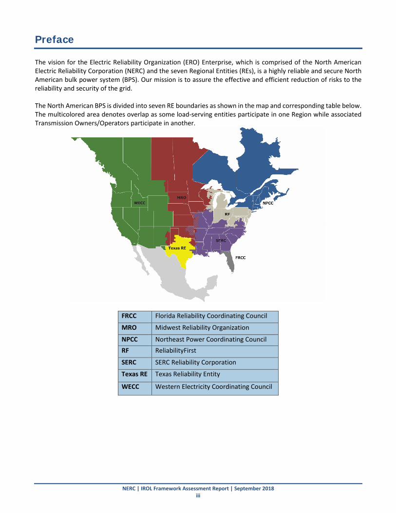
NERC | IROL Framework Assessment Report | September 2018 iii
Preface The vision for the Electric Reliability Organization (ERO) Enterprise, which is comprised of the North American Electric Reliability Corporation (NERC) and the seven Regional Entities (REs), is a highly reliable and secure North American bulk power system (BPS). Our mission is to assure the effective and efficient reduction of risks to the reliability and security of the grid. The North American BPS is divided into seven RE boundaries as shown in the map and corresponding table below. The multicolored area denotes overlap as some load-serving entities participate in one Region while associated Transmission Owners/Operators participate in another.
FRCC Florida Reliability Coordinating Council
MRO Midwest Reliability Organization
NPCC Northeast Power Coordinating Council RF ReliabilityFirst
SERC SERC Reliability Corporation
Texas RE Texas Reliability Entity
WECC Western Electricity Coordinating Council

NERC | IROL Framework Assessment Report | September 2018 iv
Executive Summary The NERC Methods for Establishing IROLs Task Force (MEITF) was formed to provide technical guidance to the Project 2015-09 FAC Standard Drafting Team (SDT) for potential revisions to the FAC standards requirements. One of the tasks assigned to the MEITF focused on reviewing the technical aspects of how IROLs are established (the “IROL framework”), and recommend potential revisions to the FAC Standards for consideration by the FAC SDT. The MEITF presented an IROL framework based on the technical rationales and consensus of industry stakeholders (MEITF membership and NERC Planning Committee (PC) and Operating Committee (OC)), including recommended revisions to the NERC FAC standards as well as proposed revisions (and additions) to the NERC Glossary of Terms to support the IROL framework and revised standards requirements. Following approval of the IROL framework by the NERC PC and OC membership, FERC staff expressed concerns regarding approval of the proposed changes to NERC Standards. Based on the concerns, the NERC MEITF attempted to develop an alternative IROL framework that the MEITF believes could be endorsed by FERC staff, based on their concerns about the approved framework. While the MEITF does not endorse this alternative framework, this document attempts to describe technical aspects of both frameworks and the potential challenges of implementing the framework that is believed to be supported by FERC staff. This includes qualitative and quantitative examples as well as discussion related to potential benefits and challenges of using either the original industry-supported IROL framework or the IROL framework to address FERC staff concerns. This document focuses on these concepts and includes the following:
• Presentation of the IROL frameworks
• Technical considerations and review of IROL frameworks
• RC questionnaire related to IROL frameworks
• Qualitative and quantitative examples of applying IROL frameworks Key Findings and Recommendations The key findings and recommendations described in Table ES.1 are describe in detail throughout this guideline, and are listed in their respective sections.
Table ES.1: Key Findings and Recommendations # Key Finding Recommendation 1 Responses from RCs regarding whether there would be an
increase in the number of IROLs if the industry adopted the framework believed to be supported by FERC varied significantly. This is dependent on existing RC practices (e.g., how they treat SOLs versus IROLs) and operating plans as well as system characteristics. Most of the increases were attributed to cascading and localized voltage instability. Some RCs stated that they would see an increase in pre-contingency load shedding due to the establishment of IROLs, as compared to existing practices.
The MEITF is providing information regarding impacts to existing practices for reference for a future SDT. A future SDT should take these findings into consideration when developing IROL-related standards requirements.
2 Instability, uncontrolled separation, or cascading needs to be quantified such that its impact to the BES is understood ahead of real-time operations. The inability to quantify impact is a serious reliability risk and warrants establishment of an IROL. The MEITF has devised a proposed term for the NERC Glossary of Terms deemed “System Instability” used to describe situations where any type of instability is either unable to be proved to be contained or proved to be too large of an impact to the overall reliability of the BES.
Any instability, uncontrolled separation, or cascading whose impact cannot be quantified should warrant establishing an IROL. On the other hand, more localized instability conditions proved to be contained to a local area ahead of real-time operations should not necessarily warrant establishing an IROL in all situations.

Executive Summary
NERC | IROL Framework Assessment Report | September 2018 v
Table ES.1: Key Findings and Recommendations # Key Finding Recommendation 3 The establishment of IROLs to prevent any instability,
uncontrolled separation, or cascading can present challenges especially for local load service areas where minor instability or cascading events may result in a small amount of load loss. The load service reliability is significantly degraded when shedding load pre-contingency compared to taking the risk of a very low probability contingency occurring that would result in the contained instability, uncontrolled separation, or cascading affective a relatively small amount of load.
Widespread impacts (impacting neighboring RCs, large areas of single RC footprint, etc.) warrant establishing an IROL. However, local instability, uncontrolled separation, or cascading that is proved to be contained to a relatively small amount should not necessarily warrant the establishment of an IROL. Local load issues, and the potential for load loss, should be left up to the local RC to make that determination based on their own risk assessment. Many RCs currently have fairly extensive risk assessment methods for determining whether to establish an IROL on a case-by-case basis.
4 Transient (angular) instability should be quantified and well understood; if the instability cannot be quantified, it warrants establishment of an IROL. Transient instability may or may not have an adverse impact to the BES, based on the system topology and criticality of generation to overall BES reliability. Generator loss of synchronism or other transient instability may not necessarily result in load loss, or the load loss may be minimal and can be restored quickly. Mitigating a unit instability with an IROL versus an SOL has little reliability benefit unless the overall BES is at risk.
Instability that is proved to have no adverse impact to the BES (i.e., does not result in tripping additional (or minimal) transmission elements or load) should not be mitigated with an IROL. Rather, an SOL with appropriate operating plans should be used to return to operating conditions that mitigate the instability.
5 The definition of cascading that currently uses the term widespread creates ambiguity on how it gets practically applied. A definition that eliminates this term is proposed by the MEITF. Some determination of acceptable versus unacceptable levels of cascading is therefore required to gain consistency across RCs for use in developing SOLs versus IROLs. Allowing some amount of load tripping during cascading is reasonable due to minor load pockets and tapped loads tripping during bounded, contained, pre-studied conditions.
Any future revisions by a FAC Standards SDT should consider updating the cascading definition in the NERC Glossary of Terms. Subsequently, any revisions to the FAC Standards requirements (or specified in the RC SOL Methodology) should then specify what is considered acceptable versus unacceptable cascading for purposes of IROL establishment. Some degree of cascading that is bounded, studied ahead of real-time operation, and proved to be contained should not warrant establishment of an IROL. Minor load loss caused by cascading should be acceptably managed through SOLs rather than through the use of an IROL.
6 Pre-contingency load shedding is not the most appropriate action to mitigate potential violations in reliability criteria, and may result in a degradation in reliability of load service. In some situations, post-contingency operator actions can suffice to eliminate the potential risk (e.g., cascading in some cases) without requiring the use of pre-contingency load shedding. Further, studies may prove a contained amount of load loss with no impact to the remaining BES, and should also suffice without taking pre-contingency action.
When the load loss amount is proved to be contained (and possibly below some acceptable level), post-contingency load loss or load tripping may be sufficient and may also improve overall reliability of load service to end-use customers. These situations should not necessarily require the use of pre-contingency load shedding and a necessary actions, and therefore may not warrant the establishment of an IROL.
7 Applying the definition of uncontrolled separation is often challenging for study engineers since reliability studies use known contingencies and operating conditions. Uncontrolled separation applied to small load pockets or generators that have no adverse impact to the BES can be problematic.
Uncontrolled separation should focus on large portions of the BES separating from the rest of the BES. These conditions are well understood in the regions that have these potential issues under certain operating conditions, and IROLs are established accordingly. However, it is not appropriate to apply this concept to smaller load pockets or individual generator(s).

Executive Summary
NERC | IROL Framework Assessment Report | September 2018 vi
Table ES.1: Key Findings and Recommendations # Key Finding Recommendation 8 The system is planned to meet the performance
requirements specified in Table 1 of TPL-001-4 while serving all firm load and including all known firm transmission commitments. If the system is operating the same condition that it was planned for, category P0, there will be no Instability, Cascading, uncontrolled separation, exceedance of facility ratings, or violation of voltage limits for the next contingency. However, since operating conditions often vary from planned conditions, the RC may need to establish IROLs that were not identified in the planning horizon. The RC may shed load pre-contingency to remain within those IROLs; whereas, the planner is prohibited from shedding pre-contingency load. This is logical since the RC may be in an operating condition more severe than the events the system was planned for. However, enhanced coordination on sensitivity studies and operating procedures used in planning and operating analyses could reduce differences between the system conditions studied by the planners and the RC.
A future SDT should consider how the TPL and FAC standards work in concert related to establishing IROLs versus developing corrective action plans to address reliability criteria in the planning horizon. Consideration should be given to the methods planners employ when utilizing operating procedures as part of the corrective action plans.
9 RCs used different methods for applying selected contingency events to the studies for establishing SOLs and IROLs.
Proposed revisions to FAC-011 should address this ambiguity in how selected contingency events in FAC-011, Requirement R5 are applied to studies to establish or set SOLs and IROLs. In particular, the RC should have flexibility in determining how selected contingencies are applied for SOLs and IROLs based on a risk assessment.
10 Unforeseen conditions (e.g., forced or urgent outages) may arise where the unplanned or unforeseen operating conditions do not match the planned, expected conditions. In those cases, priority is given to returning relatively quickly to a state where the system performs acceptably for the next contingency event. On the other hand, IROLs and other SOLs are studied and set accordingly to expected operating conditions (e.g., elements out, load levels, transfers). The limit values may be updated as real-time approaches, yet are typically set in advance.
It should be made very clear in any FAC standards revisions that IROLs are established for expected operating conditions. IROLs should be established prior to real-time operation and may be updated as real-time conditions near or during real-time operations. At the very least, the time allowed to proceed with corrective actions should be different for planned conditions (“N” system) versus following a contingency (“N-1” system) to allow considerations for risk mitigation and probability of occurrence of a second contingency. RCs should study multiple contingencies deep, particularly for stability-related SOLs and IROLs where the post-contingency risk is greater.
11 Any consideration for whether an SOL should be an IROL includes some degree of risk assessment by the RC, otherwise all SOLs related to instability, uncontrolled separation, and cascading would be considered an IROL irrespective of the severity of impact or the relative risks involved on a case-by-case basis. Risk assessment provides the RC with flexibility while ensuring some degree of consistency across all RCs.
Some degree of risk assessment should be allowed by the RC to provide flexibility in the way that IROLs are established. Requiring that all instability, uncontrolled separation, and cascading be mitigated with an IROL should be avoided because it will result in substantially more pre-contingency load shedding for instability, uncontrolled separation, and cascading conditions that are known to be bounded, contained, and have minimal risk to the overall BES.
12 The analytical techniques used for studying the impacts of instability, uncontrolled separation, and cascading are not well documented across SOL Methodologies. The Reliability
The techniques presented in the guideline should be considered by RCs when developing their SOL Methodologies.

Executive Summary
NERC | IROL Framework Assessment Report | September 2018 vii
Table ES.1: Key Findings and Recommendations # Key Finding Recommendation
Guideline: Methods for Establishing IROLs developed by the MEITF seeks to fill that technical gap and provide relevant guidance for the industry. The guideline provides technical information independent of any IROL framework or potential revisions to NERC Reliability Standards.
13 IROLs are used in a number of other NERC Reliability Standards, which can create additional burdens and compliance obligations when establishing IROLs. These links may not be necessary and have possibly led to IROLs not being used temporarily, as they should be, due to these linkages. It is possible that these linkages have discouraged the establishment of IROLs altogether.
MEITF supports the efforts by the SDT to propose revisions to NERC Reliability Standards that eliminate the link between IROLs and the other NERC Reliability Standards that are not related to real-time operations (i.e., specific FAC, IRO, and TOP NERC Reliability Standards). Those proposed revisions allow for IROLs to be established and used solely as for operating purposes. This separation should result in IROLs being used more appropriately in temporary situations such as maintenance outages. The SDT has proposed revisions to the standards to ensure that there are no reliability gaps, and that the intent of those other standards can be fulfilled.
NERC | IROL Framework Assessment Report | September 2018 1
Background The NERC Methods for Establishing IROLs Task Force (MEITF) was formed to provide technical guidance to the Project 2015-09 FAC Standard Drafting Team (SDT) for potential revisions to the FAC standards requirements. The MEITF scope of work included developing technical reference material related to the techniques and analysis for studying instability, uncontrolled separation, and cascading. The other major aspect of the MEITF work focused on reviewing the technical aspects of the IROL frameworks, and developing potential revisions to the FAC Standards for future consideration by the FAC SDT. The MEITF has developed a draft Reliability Guideline: Methods for Establishing IROLs, which is intended to provide technical guidance for analyzing instability, uncontrolled separation, and cascading. That document is a standalone reference that, once approved, should be considered for inclusion in all RC SOL Methodologies. The concepts discussed in that guideline are not discussed here. This report focuses on the IROL framework, and technical aspects related to the revision of IROL-related standards requirements. The MEITF presented a proposed IROL framework based on the technical rationales and consensus of industry stakeholders, including recommended revisions to the NERC FAC standards, to the NERC Planning Committee (PC) and Operating Committee (OC) who approved the IROL framework as presented. The NERC PC and OC also approved a set of revised terms for consideration by the FAC SDT for inclusion in the NERC Glossary of Terms that supported the IROL framework and revised standards requirements. Following approval of the IROL framework by the NERC PC and OC, FERC staff expressed concerns regarding approval of the proposed changes to NERC Standards. Based on the concerns, the NERC MEITF attempted to develop an alternative IROL framework that the MEITF believes could be endorsed by FERC staff based on their concerns about the approved framework. While the MEITF does not endorse this alternative framework, this document attempts to describe technical aspects of both frameworks and the potential challenges of implementing the framework that is believed to be supported by FERC staff. This includes qualitative and quantitative examples as well as discussion related to potential benefits and challenges of using either the original industry-supported IROL framework or the IROL framework to address FERC staff concerns. This document focuses on these concepts and includes the following:
• Presentation of the IROL frameworks
• Technical considerations and review of IROL frameworks
• RC questionnaire related to IROL frameworks
• Qualitative and quantitative examples of applying IROL frameworks
Proposed Frameworks As described above, two frameworks have been developed:
• Framework A: The IROL framework developed and supported by MEITF membership and approved by the NERC PC and OC.
• Framework B: The IROL framework developed by MEITF to address concerns relayed from FERC staff regarding Framework A.
Framework B is not supported by MEITF membership; rather, it is a significant effort by the MEITF to develop a framework that would likely be adopted by FERC based on FERC Staff comments. Framework B is provided for technical reference, and technical discussion throughout this document elaborates on the various considerations that should be made when moving forward with any framework.
Background
NERC | IROL Framework Assessment Report | September 2018 2
Note that both frameworks use the definitions that are provided in Table B.1. The definitions for Instability, System Instability, Uncontrolled Separation, and Cascading are the same as proposed by the MEITF in their originally proposed definitions that were endorsed by the NERC PC and OC. The definition for IROL was modified after receiving FERC feedback, and IROL Tv was unchanged. Framework A – Original Framework The framework presented below was developed by the NERC MEITF, and approved by the NERC Planning and Operating Committees. It was intended to provide recommendations for modifications to the FAC standards for consideration by the Project 2015-09 FAC Standards SDT related to the establishment of SOLs and IROLs governed by the SOL Methodology. The FAC Standards describe the items that are required to be addressed in each RC’s SOL Methodology, and related requirements in FAC-014 require entities to establish SOLs and IROLs consistent with the SOL Methodology. The MEITF maintains that this proposed framework portrays practices consistent with current industry efforts, and is also a significant improvement to the current status of the IROL establishment process documented in the enforceable standards. Although the framework gives a certain level of discretion to the RC regarding its assessment of IROLs, it defines clear elements and boundaries (which are nonexistent today) to incorporate in the SOL Methodology. Each Reliability Coordinator shall include in its SOL Methodology a description of how the subsets of SOLs that qualify as IROLs are established. This methodology should, at a minimum:
1. Describe the analytical techniques used to study and determine Instability, System Instability, Uncontrolled Separation, and Cascading
2. Require that IROLs are established to prevent System Instability
3. Require that loss of load greater than 2000 MW caused by Instability, Uncontrolled Separation, or Cascading is unacceptable and warrants the establishment of an IROL
4. Establish a risk assessment process for determining which SOLs should be considered IROLs to prevent an unacceptable loss of load between 300 MW and 2000 MW due to Instability, Uncontrolled Separation, or Cascading. This risk assessment process shall, at a minimum, include considerations for:
a. Amount of pre-contingency load shedding necessary
b. Resulting impacts to neighboring Reliability Coordinator Areas
c. Nature of the load (e.g., economics, criticality, geographic region, etc.) at risk
d. Restoration plans and estimated time to restore the affected load at risk
e. Risk of contingencies more severe than single contingency events Framework B – Revised Framework to Address Regulatory Concerns NERC MEITF decided to develop a framework, presented below, to address potential regulatory concerns. This framework is not supported by NERC MEITF membership. Rather, it is intended to show the contrast between frameworks and provide a venue to describe the technical aspects of each framework in a side-by-side manner.

Background
NERC | IROL Framework Assessment Report | September 2018 3
The SOL Methodology shall require that IROLs be established for expected1 operating conditions (including planned outage conditions) to prevent the Contingencies selected in (FAC-011-_) Requirement R_2 from resulting in:
1. Any System Instability
2. Any voltage Instability
3. Any transient Instability, excluding unit Instability:
a. That does not result in the apparent impedance swings causing the tripping of any Transmission system Elements other than the generating unit(s) and its directly connected Facilities.
b. Resulting in no exceedance of emergency Facility Ratings and emergency System Voltage Limits upon loss of the unit(s) due to transient Instability
4. Any Cascading resulting in load loss
5. Any Uncontrolled Separation
Table B.1: Proposed Revised Glossary Definitions Associated with IROLs
Continent-Wide Term Definition
Instability The inability of Elements of the Bulk-Power System, for a given initial operating condition, to regain a state of operating equilibrium after being subjected to a Disturbance.
System Instability3 The inability of the Bulk-Power System*, for a given initial operating condition, to regain a state of operating equilibrium after being subjected to a Disturbance. *Refers to the remaining portion of the interconnected Bulk-Power System, with the exception of the Elements disconnected as a result of the Disturbance.
Uncontrolled Separation
The unintended islanding of a portion of the Bulk-Power System that includes generation or load.
Cascading The uncontrolled successive loss of Bulk-Power System Elements triggered by a Disturbance.
Interconnection Reliability Operating Limit (IROL)
A System Operating Limit that, if exceeded, could lead to System Instability, Uncontrolled Separation, or Cascading that adversely impact the reliability of the Bulk Electric System.
IROL Tv The maximum time that an Interconnection Reliability Operating Limit can be exceeded. Each Interconnection Reliability Operating Limit’s Tv shall be less than or equal to 30 minutes.
1 “expected” refers to studies performed to assess expected or anticipated operating conditions one or more days earlier than real-time operations. The intent with this language is to convey that IROLs are not required to be established for unanticipated or unexpected operations such as forced outages or other unforeseen events over which the operator has no control. 2 Both underscores in this sentence are intended as placeholders for pointing to the appropriate requirement once integrated into the new FAC-011 standard. 3 As per the draft Reliability Guideline: “Instability that cannot be sufficiently proven via study to be contained to a pre-determined area should be identified as System Instability. In these cases, simulation results are inconclusive as to the extent or impact such an Instability may have on the BPS.”
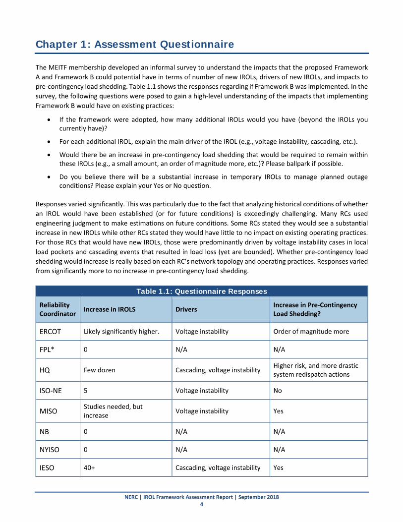
NERC | IROL Framework Assessment Report | September 2018 4
Chapter 1: Assessment Questionnaire The MEITF membership developed an informal survey to understand the impacts that the proposed Framework A and Framework B could potential have in terms of number of new IROLs, drivers of new IROLs, and impacts to pre-contingency load shedding. Table 1.1 shows the responses regarding if Framework B was implemented. In the survey, the following questions were posed to gain a high-level understanding of the impacts that implementing Framework B would have on existing practices:
• If the framework were adopted, how many additional IROLs would you have (beyond the IROLs you currently have)?
• For each additional IROL, explain the main driver of the IROL (e.g., voltage instability, cascading, etc.).
• Would there be an increase in pre-contingency load shedding that would be required to remain within these IROLs (e.g., a small amount, an order of magnitude more, etc.)? Please ballpark if possible.
• Do you believe there will be a substantial increase in temporary IROLs to manage planned outage conditions? Please explain your Yes or No question.
Responses varied significantly. This was particularly due to the fact that analyzing historical conditions of whether an IROL would have been established (or for future conditions) is exceedingly challenging. Many RCs used engineering judgment to make estimations on future conditions. Some RCs stated they would see a substantial increase in new IROLs while other RCs stated they would have little to no impact on existing operating practices. For those RCs that would have new IROLs, those were predominantly driven by voltage instability cases in local load pockets and cascading events that resulted in load loss (yet are bounded). Whether pre-contingency load shedding would increase is really based on each RC’s network topology and operating practices. Responses varied from significantly more to no increase in pre-contingency load shedding.
Table 1.1: Questionnaire Responses
Reliability Coordinator Increase in IROLS Drivers Increase in Pre-Contingency
Load Shedding?
ERCOT Likely significantly higher. Voltage instability Order of magnitude more
FPL* 0 N/A N/A
HQ Few dozen Cascading, voltage instability Higher risk, and more drastic system redispatch actions
ISO-NE 5 Voltage instability No
MISO Studies needed, but increase Voltage instability Yes
NB 0 N/A N/A
NYISO 0 N/A N/A
IESO 40+ Cascading, voltage instability Yes
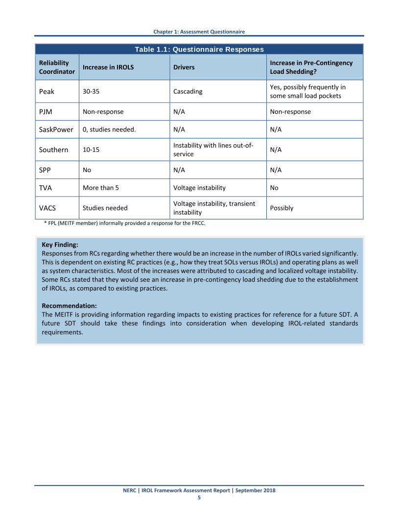
Chapter 1: Assessment Questionnaire
NERC | IROL Framework Assessment Report | September 2018 5
Table 1.1: Questionnaire Responses
Reliability Coordinator Increase in IROLS Drivers Increase in Pre-Contingency
Load Shedding?
Peak 30-35 Cascading Yes, possibly frequently in some small load pockets
PJM Non-response N/A Non-response
SaskPower 0, studies needed. N/A N/A
Southern 10-15 Instability with lines out-of-service N/A
SPP No N/A N/A
TVA More than 5 Voltage instability No
VACS Studies needed Voltage instability, transient instability Possibly
* FPL (MEITF member) informally provided a response for the FRCC.
Key Finding: Responses from RCs regarding whether there would be an increase in the number of IROLs varied significantly. This is dependent on existing RC practices (e.g., how they treat SOLs versus IROLs) and operating plans as well as system characteristics. Most of the increases were attributed to cascading and localized voltage instability. Some RCs stated that they would see an increase in pre-contingency load shedding due to the establishment of IROLs, as compared to existing practices. Recommendation: The MEITF is providing information regarding impacts to existing practices for reference for a future SDT. A future SDT should take these findings into consideration when developing IROL-related standards requirements.
NERC | IROL Framework Assessment Report | September 2018 6
Chapter 2: Considerations for an IROL Framework This section describes technical considerations that should be strongly considered when developing a framework for IROL-related standards requirements. These should be considered for any future FAC standards revisions. Two key principles that the MEITF believes need to be stated up front include:
• Use of SOLs: It is critical to understand that both frameworks use SOLs to address all cascading, instability, and uncontrolled separation. The difference between the frameworks is that Framework A provides flexibility in using SOLs to address some forms of instability, uncontrolled separation, and cascading (rather than using an IROL), and reserves IROLs for instability, uncontrolled separation, and cascading that impacts a more substantial portion of the BES. On the other hand, Framework B uses IROLs to address almost all forms of instability, uncontrolled separation, and cascading regardless of impact.
• MEITF Position: The MEITF strongly disagrees with the principles and implications behind the framework that is believed to be endorsed by FERC staff (Framework B, presented below). Namely, the concept that almost all SOLs with potential post-contingency acceptable bounded loss of elements or load should be classified as IROLs and mitigated as such poses significant issues with reliable operation of the BES as well as providing reliable load service. It is widely recognized that IROLs are a means to put an additional level of scrutiny on parts of the system where reliability of the interconnection could be compromised if the critical contingency were to occur. The MEITF contends that using SOLs to avoid instability, uncontrolled separation, and cascading does not imply that those phenomena are acceptable. The existing SOL framework and body of NERC Reliability Standards, along with the proposed improvement by the FAC SDT, requires engineering analysis and operating plans to ensure reliable operation of the BES. However, the MEITF discussions and examples revealed that establishing IROLs to manage almost all limits (as proposed by FERC staff) would not be logical, would pose significant compliance burden, and be detrimental to BES reliability.
The following topics are described in detail in subsequent subsections of this report:
• Quantifying Impacts: Any instability, uncontrolled separation, or cascading should be quantified such that its impact on the BES is well understood heading into real-time operations. Any instability, uncontrolled separation, or cascading whose impact cannot be quantified should warrant establishing an IROL. Other local areas that can be quantified and contained to a pre-defined area of impact may not warrant establishing an IROL in all situations.
• Load Loss Threshold: Use of a load loss threshold in the IROL framework was proposed and subsequently unsupported by FERC Staff. Both the use of a load loss threshold and the unlikelihood that FERC staff will support this should be considered when developing Reliability Standards requirements.
• Considering Local Load Service: IROLs should protect the overall interconnection from potential widespread reliability issues rather than addressing local load service issues. The ramifications of establishing an IROL for these issues may result in reduced reliability for end-use customers. As more IROLs are established for local issues, where mitigation options are limited, it is expected that there will be more instances of pre-contingency load shedding that will be required to remain below the IROL. This translates to reduced reliability for those end-use customers.
• Forms of Transient Instability: Some forms of transient instability do not warrant the establishment of an IROL and can be managed with an SOL (e.g., local unit(s) instability that is proven to have no negative reliability impact to the rest of the interconnection).
• Bounded Cascading and Load Loss: Updates to the cascading definition should improve its application for use when establishing IROLs, and some forms of cascading that are proved to be contained with some bounded load loss should not warrant establishment of an IROL.

Chapter 2: Considerations for an IROL Framework
NERC | IROL Framework Assessment Report | September 2018 7
• Pre-Contingency Load Shedding: Some situations may warrant allowing post-contingency load shedding when time is allowed to take operator actions. Not all SOLs should necessitate pre-contingency load shedding action by the system operator. However, establishing and communicating ratings is paramount.
• Analyzing Uncontrolled Separation: Uncontrolled separation should focus on large portions of the BES separating from the rest of the BES. These conditions are well understood in the regions that have these potential issues under certain operating conditions, and IROLs are established accordingly. However, it is not appropriate to apply this concept to smaller load pockets or individual generator(s).
• Alignment Issues between Planning and Operations: Future efforts should consider ways in which the NERC TPL and FAC standards can work in concert related to establishing operating limits versus developing corrective action plans. Performance criteria between the two horizons should be relatively uniform, yet mitigating actions may be different in each horizon. Mainly, the way planners perform studies may not be aligned with the reality of the operations horizon, and IROLs are a very stringent concept for operators versus what the system was planned for.
• Contingency Selection: Proposed revisions to FAC-011 should address the ambiguity in how selected contingency events in the current draft version 4 of FAC-011, Requirement R5 are applied to studies to establish or set SOLs and IROLs. In particular, the RC should have flexibility in determining how selected contingencies are applied for SOLs and IROLs based on a risk assessment.
• Establishing IROLs for Expected Operating Conditions: IROLs are established to prevent adverse impacts for the next single contingency or credible multiple contingency for expected operating conditions. IROLs should be established prior to real-time operation and the limit values may be updated as real-time conditions near or during real-time operations. IROLs are not required to be established in same-day or real-time for unexpected operations such as forced outages or other unforeseen events over which the RC has no control. While such conditions need to be mitigated, these mitigations occur outside the auspices of the IROL.
• Understanding Risk: Risk assessment should be allowed by the RC to provide flexibility in the way that IROLs are established. Requiring that all instability, uncontrolled separation, and cascading be mitigated with an IROL could result in substantially more pre-contingency load shedding for instability, uncontrolled separation, and cascading that are known to have minimal risk to the overall BES. A clear distinction must be made between load service and overall system integrity/reliability for low probability, high impact events.
• Recommended Analytical Methods: The Reliability Guideline: Methods for Establishing IROLs provides detailed reference material from which RCs should pull pertinent information to develop effective SOL Methodologies. All RC SOL Methodologies should be reviewed such that they provide explicit documentation on how instability, uncontrolled separation, and cascading are analyzed and how each are characterized as IROLs. This alone will result in a significant improvement in gaining consistency across RC SOL Methodologies and in executing studies consistently.
• Separation of IROLs from Use in Other Reliability Standards: The MEITF is aware that the FAC SDT is revising other Reliability Standards to eliminate the linkage between IROLs and other activities. The MEITF supports this approach and believes the affected standards can be addressed in other ways. This may lead to a willingness to use operating limits more appropriately since there are less external ramifications that are unrelated to real-time operation.
Quantifying Impact The MEITF agreed unanimously that any instability, uncontrolled separation, or cascading should be quantified such that its impact on the BES is well understood heading into real-time operations. Any instability, uncontrolled separation, or cascading whose impact cannot be quantified should warrant establishing an IROL. All RCs agreed

Chapter 2: Considerations for an IROL Framework
NERC | IROL Framework Assessment Report | September 2018 8
that, while conservative and stringent, this concept is built into their existing practices today. The MEITF has even devised a proposed term for the NERC Glossary of Terms deemed “System Instability” used to describe situations where any type of instability is either unable to be proved to be contained or proved to be too large of an impact to the overall reliability of the BES. On the other hand, the MEITF also agreed that more localized instability conditions that are proved to be contained to a local area ahead of real-time operations may not warrant establishing an IROL in all situations. Under certain operating conditions, some load may be at risk of loss due to instability, uncontrolled separation, and cascading. However, the loss of load due to the instability, uncontrolled separation, or cascading should be relatively small in electrical size (MW) as well as geographic size (only a relatively small group of buses). Examples of situations that may not necessarily warrant the establishment of an IROL, according to the MEITF, could include:
• Voltage instability of a small local load pocket where the boundary of the instability is quantified and proved to be local to a specific number of buses (see Figure 2.1).
• Cascading that is proved to be contained (see Figure 2.2). Cascading analysis may show that multiple elements could subsequently trip; however, in many cases, the cascading is bounded to only a small number of elements and does not spread to a wide area.
Both Framework A and B use the term “System Instability” to clearly differentiate those types of instability that are not quantifiable or that have a significant impact on interconnection reliability. Framework A provides flexibility to the RC to apply a risk framework for instability, uncontrolled separation, and cascading that is quantified to be contained to a specific area (and load loss amount). On the other hand, Framework B does not allow for load loss caused by these phenomena and therefore quantifying the impact is not as relevant. Framework B does not provide flexibility to the RC, and states that instability (excluding unit instability), uncontrolled separation, and cascading should be mitigated with an IROL in almost all instances. Regardless, the MEITF still believes that explicitly calling out System Instability is an effective means of gaining consistency across industry.
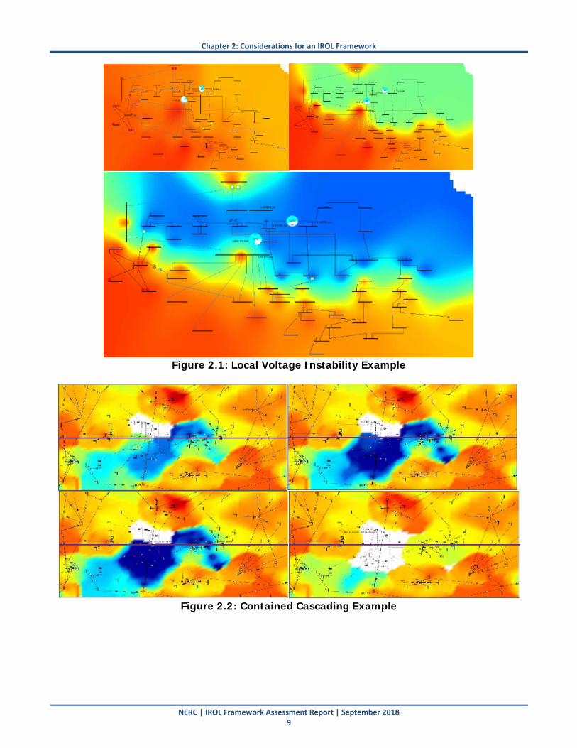
Chapter 2: Considerations for an IROL Framework
NERC | IROL Framework Assessment Report | September 2018 9
Figure 2.1: Local Voltage Instability Example
Figure 2.2: Contained Cascading Example
Chapter 2: Considerations for an IROL Framework
NERC | IROL Framework Assessment Report | September 2018 10
Considering Local Load Service The MEITF discussed at length the potential situations where IROLs should be used to protect against instability, uncontrolled separation, and cascading. The MEITF agreed that widespread impacts (impacting neighboring RCs, large areas of single RC footprint, etc.) warrant establishing an IROL. However, the MEITF disagreed with FERC Staff regarding the situations in which IROLs should protect against local instability, uncontrolled separation, or cascading condition (particularly the instability events). In the real-time operations horizon, IROLs are intended to protect against fairly large-scale or widespread impacts to the BES and not necessarily local load issues. Instability of local load pockets or cascading that results in small amounts of tapped load, for example, should not justify establishment of an IROL. Many of the situations where the potential establishment of an IROL becomes problematic involve using an IROL to prevent any instability or any cascading event, particularly in local load pockets. The NERC TPL Reliability Standard allows for shedding non-consequential load loss between an N-1 contingency and another N-1 contingency (N-1-1 situation). The planner can shed the load either after the first contingency or after the second, depending on practices. The operating conditions where these issues arise in real-time is almost never all-lines-in-service conditions, and typically involves one or more line outages in the initial operating state. Rather than establish an IROL and invoke shedding load pre-contingency, the RCs have opted to take the risk of potential contained instability or cascading in these situations. The amount of load loss may be higher, but the likelihood of the critical contingency occurring is very low. Therefore, from a risk perspective, it is logical to assume that risk to ensure continuity of serving load to the greatest extent possible. The illustrative examples in Chapter 3 highlight the issue of serving the load with the highest degree of service, and how establishing an IROL to prevent post-contingency load loss by regularly shedding load pre-contingency is rarely an economical or reliable practice.
Key Finding: Instability, uncontrolled separation, or cascading needs to be quantified such that its impact to the BES is understood ahead of real-time operations. The inability to quantify impact is a serious reliability risk and warrants establishment of an IROL. The MEITF has devised a proposed term for the NERC Glossary of Terms deemed “System Instability” used to describe situations where any type of instability is either unable to be proved to be contained or proved to be too large of an impact to the overall reliability of the BES. Recommendation: Any instability, uncontrolled separation, or cascading whose impact cannot be quantified should warrant establishing an IROL. On the other hand, more localized instability conditions proved to be contained to a local area ahead of real-time operations should not necessarily warrant establishing an IROL in all situations.
Chapter 2: Considerations for an IROL Framework
NERC | IROL Framework Assessment Report | September 2018 11
Forms of Transient Instability The NERC TPL-001-4 Reliability Standard, Requirement R4.1 (shown below) states that generating units are not allowed to pull out of synchronism for P1 single contingencies with normal system initial conditions. However, in real-time operations, the system is very rarely operated with all elements in service. Typically multiple elements are out-of-service and the system is not operating near the studied conditions from the long-term planning horizon. Therefore, it is generally reasonable to associate any real-time operating condition as already beyond an all-lines-in-service state. TPL-001-4 states that for P2 through P7 contingencies, a generator is allowed to pull out of synchronism in simulation so long as the apparent impedance swings do not result in tripping of any transmission elements other than the generating unit and its directly connected facilities. It therefore would be reasonable to extend this concept to real-time operations and allow for units to lose synchronism so long as their instability does not negatively impact the rest of the BES.
4.1. Studies shall be performed for planning events to determine whether the BES meets the performance requirements in Table 1 based on the Contingency list created in Requirement R4, Part 4.4.
4.1.1. For planning event P1: No generating unit shall pull out of synchronism. A generator being disconnected from the System by fault clearing action or by a Special Protection System is not considered pulling out of synchronism.
4.1.2. For planning events P2 through P7: When a generator pulls out of synchronism in the simulations, the resulting apparent impedance swings shall not result in the tripping of any Transmission system elements other than the generating unit and its directly connected Facilities.
4.1.3. For planning events P1 through P7: Power oscillations shall exhibit acceptable damping as established by the Planning Coordinator and Transmission Planner.
Unless transient instability (or other controls-related instability) of generating units causes adverse impacts to the BES, these types of instability should not warrant establishment of IROLs. One or multiple units may lose synchronism during rare outage conditions if the critical contingency were to occur. Yet that instability can be proved via simulation ahead of time to have no impact on the remaining BES. Figure 2.3 shows an example of rotor angles where one generator is losing synchronism compared to the rest of the system. This may occur at a
Key Finding: The establishment of IROLs to prevent any instability, uncontrolled separation, or cascading can present challenges especially for local load service areas where minor instability or cascading events may result in a small amount of load loss. The load service reliability is significantly degraded when shedding load pre-contingency compared to taking the risk of a very low probability contingency occurring that would result in the contained instability, uncontrolled separation, or cascading affective a relatively small amount of load. Recommendation: Widespread impacts (impacting neighboring RCs, large areas of single RC footprint, etc.) warrant establishing an IROL. However, local instability, uncontrolled separation, or cascading that is proved to be contained to a relatively small amount should not necessarily warrant the establishment of an IROL. Local load issues, and the potential for load loss, should be left up to the local RC to make that determination based on their own risk assessment. Many RCs currently have fairly extensive risk assessment methods for determining whether to establish an IROL on a case-by-case basis.
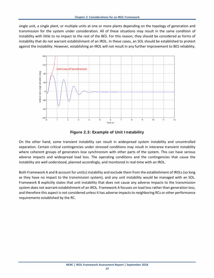
Chapter 2: Considerations for an IROL Framework
NERC | IROL Framework Assessment Report | September 2018 12
single unit, a single plant, or multiple units at one or more plants depending on the topology of generation and transmission for the system under consideration. All of these situations may result in the same condition of instability with little to no impact to the rest of the BES. For this reason, they should be considered as forms of instability that do not warrant establishment of an IROL. In these cases, an SOL should be established to protect against the instability. However, establishing an IROL will not result in any further improvement to BES reliability.
Figure 2.3: Example of Unit Instability On the other hand, some transient instability can result in widespread system instability and uncontrolled separation. Certain critical contingencies under stressed conditions may result in interarea transient instability where coherent groups of generators lose synchronism with other parts of the system. This can have serious adverse impacts and widespread load loss. The operating conditions and the contingencies that cause the instability are well understood, planned accordingly, and monitored in real-time with an IROL. Both Framework A and B account for unit(s) instability and exclude them from the establishment of IROLs (so long as they have no impact to the transmission system), and any unit instability would be managed with an SOL. Framework B explicitly states that unit instability that does not cause any adverse impacts to the transmission system does not warrant establishment of an IROL. Framework A focuses on load loss rather than generation loss, and therefore this aspect is not considered unless it has adverse impacts to neighboring RCs or other performance requirements established by the RC.
Chapter 2: Considerations for an IROL Framework
NERC | IROL Framework Assessment Report | September 2018 13
Bounded Cascading and Load Loss The MEITF discussed at length the existing definition of cascading, and the challenge with including “widespread” in the definition since it leaves the application of the definition up to interpretation. The MEITF proposed a definition, shown below, that addresses this issue and clarifies the phenomena of cascading.
Cascading: The uncontrolled successive loss of System Elements triggered by a Disturbance. Using this definition, it is necessary to clarify the types of cascading that can be managed with an SOL (from a risk perspective) versus the types of cascading that warrant establishment of an IROL, and those operating limits should be established accordingly. The MEITF believes the most appropriate approach is to either define this in the FAC Standards requirements or leave it up to the SOL Methodology of each RC. However, it is acknowledged that some consistency in methods across all RCs would also gain consistency in developing IROLs to mitigate these conditions. For example, the overload threshold and its application to cascading methodologies is known to have inconsistencies among RCs across all interconnections. Disallowing any amount of load loss caused by cascading is unrealistic and should not be the primary focus for establishing IROLs. Often times, a single subsequent overload may cause a minor load pocket to trip or tapped load off a transmission circuit to trip. These small loads tripping often help mitigate the sequence of cascading events, and often the cascading is bounded, studied, and contained. Entities are required to study this, and will use SOLs with operating plans to mitigate any overloads or violations in voltage criteria. The minor risk of cascading, with low probability of multiple thermal overloads with no operator action between contingencies, should not warrant establishing an IROL and therefore mandating potential use of pre-contingency load shedding. Framework A allows for some flexibility in the RC establishing an IROL for cascading as part of its risk assessment. It allows some bounded amount of load loss caused by cascading before an SOL warrants becoming an IROL, and addresses the other cascading cases with SOLs and operating plans. On the other hand, Framework B does not allow any load loss as a result of cascading, and warrants establishing an IROL in all cases of load loss.
Key Finding: Transient (angular) instability should be quantified and well understood; if the instability cannot be quantified, it warrants establishment of an IROL. Transient instability may or may not have an adverse impact to the BES, based on the system topology and criticality of generation to overall BES reliability. Generator loss of synchronism or other transient instability may not necessarily result in load loss, or the load loss may be minimal and can be restored quickly. Mitigating instability that does not have an adverse impact to the BES with an IROL versus an SOL has little reliability benefit unless the overall BES is at risk. Recommendation: Instability that is proved to have no adverse impact to the BES (i.e., does not result in tripping additional (or minimal) transmission elements or load) should not be mitigated with an IROL. Rather, an SOL with appropriate operating plans should be used to return to operating conditions that mitigate the instability.
Chapter 2: Considerations for an IROL Framework
NERC | IROL Framework Assessment Report | September 2018 14
Pre-Contingency Load Shedding In many cases, actions taken to mitigate an SOL exceedance in the post-contingency state may improve reliability of load service since the risk of the contingency actually occurring is very rare and the post-contingency action can sufficiently address the reliability issue. Some phenomena have sufficient time for operators to react post-contingency (e.g., cascading), although others likely do not (e.g., transient voltage instability). However, once an IROL has been established, in accordance with IRO-009-2, Requirement R1, operator actions up to and including pre-contingency load shedding must be implemented to prevent and mitigate exceeding the IROL (and eliminating an exceedance within its IROL Tv), effectively precluding the use of post-contingency actions to mitigate issues (which would improve load service reliability). Cascading is an example of a phenomena that likely could allow for post-contingency operator action over pre-contingency load shedding. The MEITF has provided numerous examples of situations where bounded cascading could exist under certain N-x operating conditions. Figure 2.4 shows a simple example of a local load pocket. If one 230 kV line is out-of-service, then contingency analysis shows overloading on the 115 kV line for potential outage of the other 230 kV line. The TP has decided, as appropriate and allowable in the NERC TPL-001-44 standard, to not construct a new transmission circuit to serve this small load pocket. Rather, during forced or planned maintenance outages (which are already reduced and managed around peak conditions accordingly), the operator has chosen to take a risk of potential cascading that would only sever the load pocket from the rest of the BES and result in a small amount of load tripping.
4 The proposed NERC Reliability Standard TPL-001-5 being drafted will account for planned maintenance outages. However, the concept of allowing load shedding after the second outage in an N-1-1 (after the maintenance outage is taken) remains.
Key Finding: The definition of cascading that currently uses the term widespread creates ambiguity on how it gets practically applied. A definition that eliminates this term is proposed by the MEITF. Some determination of acceptable versus unacceptable levels of cascading is therefore required to gain consistency across RCs for use in developing SOLs versus IROLs. Allowing some amount of load tripping during cascading is reasonable due to minor load pockets and tapped loads tripping during bounded, contained, pre-studied conditions. Recommendation: Any future revisions by a FAC Standards SDT should consider updating the cascading definition in the NERC Glossary of Terms. Subsequently, any revisions to the FAC Standards requirements (or specified in the RC SOL Methodology) should then specify what is considered acceptable versus unacceptable cascading for purposes of IROL establishment. Some degree of cascading that is bounded, studied ahead of real-time operation, and proved to be contained should not warrant establishment of an IROL. Minor load loss caused by cascading should be acceptably managed through SOLs rather than through the use of an IROL.

Chapter 2: Considerations for an IROL Framework
NERC | IROL Framework Assessment Report | September 2018 15
Figure 2.4: Example Cascading System
In this example, an SOL is established and operated to regardless of whether an IROL exists. However, if an IROL were established (that is, if the SOL were considered an IROL), then pre-contingency load shedding may be necessary to mitigate the potential overload of the 115 kV circuit if one of the 230 kV lines is out of service. Again, while the operator takes these outages during conditions where these potential overloads are minimized, some situations may warrant taking these outages when the overload could exist if the contingency were to occur (e.g., forced outages, prolonged maintenance outages). Assume the 115 kV line is overloaded to 120% in RTCA with one of the 230 kV lines out for maintenance. To mitigate this RTCA post-contingency violation, 10 MW needs to be reduced in the load pocket, and all other potential operator actions have been exhausted. The operator knows that if the overload occurs, the time-overcurrent characteristic of the line provides some time less than 15 mins for the operator to take action (yet knows that this is likely around 5 minutes). The operator feels comfortable that he/she can shed 10 MW of load post-contingency if the contingency were to occur, rather than pre-emptively trip the 10 MW prior to the contingency occurring. This improves reliability of load service and addresses the reliability issue accordingly. These types of actions should be allowable rather than requiring pre-contingency load shedding. In scenarios where a there is no time to take post-contingency actions, and a contingency of the remaining 230 kV line would be expected to result in the tripping of the remaining 115 kV line resulting in loss of the contained load pocket, the operators should be allowed to perform the risk assessment and make the decision of whether or not to shed load pre-contingency or to risk the loss of the load pocket should the contingency occur.
Key Finding: Pre-contingency load shedding is not the most appropriate action to mitigate potential violations in reliability criteria, and may result in a degradation in reliability of load service. In some situations, post-contingency operator actions can suffice to eliminate the potential risk (e.g., cascading in some cases) without requiring the use of pre-contingency load shedding. Further, studies may prove a contained amount of load loss with no impact to the remaining BES, and should also suffice without taking pre-contingency action. Recommendation: When the load loss amount is proved to be contained (and possibly below some acceptable level), post-contingency load loss or load tripping may be sufficient and may also improve overall reliability of load service to end-use customers. These situations should not necessarily require the use of pre-contingency load shedding and therefore may not warrant the establishment of an IROL.

Chapter 2: Considerations for an IROL Framework
NERC | IROL Framework Assessment Report | September 2018 16
Uncontrolled Separation Analysis Considerations As part of developing the Reliability Guideline: Methods for Establishing IROLs, the MEITF discussed the difficulty of analyzing uncontrolled separation. In many cases, uncontrolled separation takes the form of instability (either local or widespread) or cascading, depending on how quickly the phenomena occurs. For example, a sequence of overloads may result in a portion of the system separating, which is considered cascading. If no further cascading risk exists, this is considered a bounded cascade even if some portion of load is tripped. On the other hand, a voltage collapse or transient instability may cause a part of a load pocket or generator(s) to trip off-line. Both of these cases could be considered uncontrolled separation, yet (as previously described) could potentially be managed by an SOL due to their proven containment. It becomes challenging to analyze uncontrolled separation in many situations since the reliability studies used to establish or set SOLs and IROLs use a pre-determined set of contingencies and operating conditions. Any known actions (e.g., protective relaying, remedial action schemes, and safety nets) are modeled and studied accordingly, and considered controlled actions. Therefore, any separation of load or generation should not be considered uncontrolled separation in these cases. Some regions have known system instability conditions that could be considered uncontrolled separation, where large portions of the BES may separate from the rest of the BES. Other areas do not have these issues, and struggle with how to apply the definition of uncontrolled separation to their systems. It seems appropriate to keep uncontrolled separation focused on large portions of the BES rather than individual load buses or load pockets that could get separated for certain contingency under specific operating conditions.
Alignment Issues between Planning and Operations Table 1 of TPL-001-4 provides the planning events that must be studied and their performance requirements. For all planning events instability, cascading, and uncontrolled separation shall not occur. If any of these phenomena occur due to a planning event, planners must develop a Corrective Action Plan to resolve the performance deficiency (R2.7.1). The Corrective Action Plan may include operating procedures such as the use of IROLs or SOLS. R1 states that items in the Corrective Action Plan must be included in the system models that represent normal system conditions, category P0. Therefore, any IROL or SOL developed as part of a Corrective Action must not reduce load or interrupt firm transmission service pre-Contingency or it would violate the performance requirements for category P0. Otherwise, it is allowable for planners to use and model operating limits that if violated would result in instability, cascading, and uncontrolled separation for the next P1-P7 event. Although not currently required by the NERC standards, these limits should be communicated to the RC for them to evaluate and possibly establish IROLs. Additionally, planners are not permitted to shed load following a single outage in order to meet system performance requirements for the next outage. Table 1 shows that the initial conditions
Key Finding: Applying the definition of uncontrolled separation is often challenging for study engineers since reliability studies use known contingencies and operating conditions. Establishing IROLs for uncontrolled separation resulting in small load pockets or generators that have no adverse impact to the BES can be problematic. Recommendation: Uncontrolled separation should focus on large portions of the BES separating from the rest of the BES. These conditions are well understood in the regions that have these potential issues under certain operating conditions, and IROLs are established accordingly. However, it is not appropriate to apply this concept to smaller load pockets or individual generator(s).

Chapter 2: Considerations for an IROL Framework
NERC | IROL Framework Assessment Report | September 2018 17
for P3 and P6 events are the loss of a single BES facility with system adjustments and footnote 9 states that the adjustments must not include non-consequential load loss. Table 1 of TPL-001-4 also states that facility ratings must not be exceeded and planned system adjustments are only allowable if they can be executed within the time duration applicable to the facility ratings. If the system remains within short-term facility ratings then operating procedures involving post-contingency actions can be used. However, if the highest facility rating for a given facility is exceeded then post-contingency operating procedures cannot be used. Any pre-contingency operating procedures could include the use of operating limits; however, they must not include reductions to load or firm transmission service. While operational studies that determine SOLs and IROLs stress the study parameters to cover for the worst case scenarios, in planning studies that might not be the case. TPL-001-4 Requirements R2.1.4 and R2.4.3 state that “Planning Assessment must vary one or more of the following conditions by a sufficient amount to stress the System within a range of credible conditions that demonstrate a measurable change in System response.” However, Requirement R2.7 states that “Corrective Action Plan(s) do not need to be developed solely to meet the performance requirements for a single sensitivity case analyzed in accordance with Requirements R2, Parts 2.1.4 and 2.4.3.” Therefore, the sensitivity studies may identify potential issues in the planning horizon but CAPs do not need to be developed to address those issues before the studied conditions become a reality in the operations horizon. If operating conditions are similar to the normal system conditions, represented by category P0 in the planning assessment, then the system is operating in the same state that it was planned for and the next P1-P7 contingency will not result in instability, uncontrolled separation, cascading, exceedance of facility ratings, or violation of voltage limits. However, operating conditions often vary significantly from planned conditions for three common reasons:
1. Planning studies generally do not capture multiple facilities out-of-service pre-contingency
2. RCs typically stress the system beyond planned conditions to determine SOLs/IROLs
3. RCs may not utilize the same operating procedures that planners developed in their Corrective Action Plans
From an operating perspective, the next single contingency represents an N-1 scenario, regardless of how many transmission or generation outages are already in effect. This would be equivalent to an initial condition represented by N-X. In planning assessments, only known outages with duration of at least six months are included in planning models. This results in a relatively small number of outages in the P0 case, compared to the number of facilities that typically unavailable on any given day. As a result, RCs are often required to operate to events that exceed what the system was planned for. Note that planning assessments may include extreme event studies that include a larger number of facilities out-of-service pre-contingency; however, planners typically do not develop Corrective Action Plans for extreme events. RCs perform studies designed to stress the system in order to establish SOLs/IROLs. Planners may perform similar sensitivity analyses and instability, uncontrolled separation, and cascading are more likely to result from P1-P7 events in these conditions. However, R2.7 states that Corrective Action Plans do not need to be developed solely to meet the performance requirements from a single sensitivity case. Therefore, planners may choose not to develop any Corrective Action Plans, including using operating limits, to resolve identified performance deficiencies. TPL-001-4 R2.7.1 requires planners to develop Corrective Action Plans, which may include operating procedures, to resolve performance deficiencies. These operating procedures must be included in the base case representing

Chapter 2: Considerations for an IROL Framework
NERC | IROL Framework Assessment Report | September 2018 18
normal system conditions, category P0. Currently, there are no NERC requirements for these procedures to be reviewed or approved by the RC. This is particularly problematic when Corrective Action plans use operating limits or other pre-contingency operating procedures to prevent instability, uncontrolled separation, or cascading for the next contingency. If the RC does not perform these pre-contingency actions, they will be operating in a different state from what the system was not planned for. When an IROL is established, the RC may have no options other than to drop load pre-contingency to prevent instability, cascading and uncontrolled separation. Similarly, when an SOL is established, the RC may need to decide between dropping load pre-contingency or exceeding facility ratings for the next contingency is warranted. Contrastingly, planners are prohibited from dropping load pre-contingency, excluding for situations beyond their control as described in R2.7.3. The MEITF does not consider this to be an alignment issue since the RC may need to operate to more severe events than what TPL-001-4 requires and the planner always has options beyond dropping load pre-contingency; whereas, the RC may not. However, the MEITF does believe that enhanced coordination between planners and the reliability coordinator would be beneficial during the development of corrective action plans that utilize operating procedures. There may also be benefits in coordinating the sensitivity studies that are performed in planning assessments with the studies used to determine IROL/SOLs in the operating horizon.
Contingency Selection Requirement R5 in the proposed FAC-011-4 standard states that RC shall identify in its SOL Methodology the contingencies for use in determining stability limits and in OPAs and RTAs, and includes:
• Defined N-1 contingencies
• Additional N-1 or multiple contingencies
• Additional N-1 or multiple contingencies provided by the PC in accordance with FAC-015. A potential issue (lack of clarity and inconsistency) arises in how those selected contingencies get applied in the studies performed in the OPAs, RTAs, and in establishing stability limits. In particular, it is not clear in the current or proposed standards whether the full set of selected contingencies need to be applied to both SOLs and IROLs, or if different sets of contingencies can be selected by the RC. For example, RC 1 may use credible multiple
Key Finding: The system is planned to meet the performance requirements specified in Table 1 of TPL-001-4 while serving all firm load and including all known firm transmission commitments. If the system is operating the same condition that it was planned for, category P0, there will be no instability, uncontrolled separation, cascading, exceedance of facility ratings, or violation of voltage limits for the next contingency. However, since operating conditions often vary from planned conditions, the RC may need to establish IROLs that were not identified in the planning horizon. The RC may shed load pre-contingency to remain within those IROLs; whereas, the planner is prohibited from shedding pre-contingency load. This is logical since the RC may be in an operating condition more severe than the events the system was planned for. However, enhanced coordination on sensitivity studies and operating procedures used in planning and operating analyses could reduce differences between the system conditions studied by the planners and the RC. Recommendation: A future SDT should consider how the TPL and FAC standards work in concert related to establishing IROLs versus developing corrective action plans to address reliability criteria in the planning horizon. Consideration should be given to the methods planners employ when utilizing operating procedures as part of the corrective action plans.
Chapter 2: Considerations for an IROL Framework
NERC | IROL Framework Assessment Report | September 2018 19
contingencies for establishing SOLs only while RC 2 may use credible multiple contingencies for establishing IROLs just like SOLs. A potential solution to this issue in the new proposed FAC-011, Requirement R5, is to specify how those contingencies are intended to be applied to both SOLs and IROLs. Another solution is to be explicit in allowing the RC flexibility in how contingencies are selected. Either way, this should be made clear in future standards revisions. The MEITF believes that the RC should have flexibility to perform a risk assessment to determine the contingencies that should be operated to for SOLs and for IROLs. The SOL Methodology should explicitly describe in detail that N-1 contingencies should apply to SOLs and IROLs, and should also describe the method for selecting credible multiple contingencies for SOLs and IROLs.
Establishing IROLs for Expected Operating Conditions It should be made very clear in any FAC standards revisions that IROLs are established for expected operating conditions. IROLs should be established prior to real-time operation and the limit values may be updated as real-time conditions near or during real-time operations. TOPs and RCs are required to study these expected operating conditions ahead of real-time operation, so this paradigm that IROLs should be established in this timeframe (or earlier) aligns well with the study process. Currently, there are no requirements related to how and when studies are performed to establish or identify operating limits for N-1-1 conditions. This may lead to situations where the RC is in an “unknown operating state” immediately following an actual contingency occurring. The potential reliability gap for operation in an “unknown operating state” was created by the retirement of TOP-004-2 Requirement 4 (March 31, 2017). While suitable for the pre-contingency operation and expected operating conditions, the OPA and RTA concepts used in the development of TOP-001-4 Requirements 12, 13 and 14 do not adequately cover for unexpected operating conditions and the post-contingency operation as described here. The RC knows that they were in an N-1 secure operating state before the contingency (no violation of emergency limits post-contingency). However, the RC must now assess whether they are in a new N-1 secure operating state. This N-1-1 condition is not required to be studied before the first N-1 by the existing standards, so inherently an “unknown operating state” could exist as soon as any forced outage occurs on the BPS. Some guidance or framework is needed to require additional studies to be performed to study multiple contingencies deep for known stability limits. For example, assume the system is operated in an N-1 secure operating state (within all SOLs and IROLs for pre- and post-contingency conditions). A contingency occurs and, as expected, the system is within all its emergency limits. Now the system is operated in a new “N-0” initial state with that element out of service that likely was not studied ahead of time. Just after the contingency event occurs, subsequent real-time assessments are based on
Key Finding: RCs used different methods for applying selected contingency events to the studies for establishing SOLs and IROLs. The FAC SDT’s current draft of FAC-011-4 does not specify how the RC’s contingency list are intended to be applied in studies – i.e., are they being applied to assess the establishment of a SOL or an IROL. Recommendation: Proposed revisions to FAC-011 should address this ambiguity in how selected contingency events in FAC-011 and should be documented in the RC’s SOL methodology. Requirement R5 is applied to studies to establish or set SOLs and IROLs. In particular, the RC should have flexibility in determining how selected contingencies are applied for SOLs and IROLs based on a risk assessment.
Chapter 2: Considerations for an IROL Framework
NERC | IROL Framework Assessment Report | September 2018 20
this new N-0 state and may indicate unacceptable N-1 system performance until adjustments are made. The question arises of how to handle this situation with regard to IROL establishment. Most RCs study multiple contingencies deep in offline studies (e.g., seasonal studies, special assessments, and some OPAs) for these purposes so they are prepared for outage conditions. However, as soon as the contingency occurs, the system is expected to be returned to an operating state that is within all SOLs and IROLs for pre- and post-contingency operating conditions. The SOL or IROL limit may need to be updated (particularly for stability cases) and the system will have to be readjusted. Unforeseen operating conditions (extreme unexpected demand levels, unforeseen forced outage conditions, etc.) may configure the system in an operating condition that was not pre-planned or pre-studied. In these cases, the focus should not be on establishing a new IROL (or SOL) within a specified period of time. The focus should be on returning the system to a state that the system operator knows is safe for the next single contingency or credible multiple contingency. This may require drastic action, up to and including load shedding, and many RCs refer to this as “IROL-like conditions” where urgent action is taken to return to a state where the system performs acceptably for the next contingency event. However, these relatively unexpected and rare operating conditions should not necessarily lead to the constant establishment and removal of IROLs. Operating plans should be developed to account for these types of conditions, and those plans should include relatively drastic action to return to expected or studied conditions fairly quickly. The MEITF discussed this at length, and proposes that stability-related SOLs (which could be IROLs) that have been defined in the OPA (or pre-defined some time before) should be studied for ensuring N-1 security for after the contingency occurs. This ensures that operating plans are feasible after the first contingency were to occur to bring the system back to a secure operating state. For stability-related SOLs and IROLs, this is critical since there may not be a time duration associated with the post-contingency risk. For any N-1 or credible N-2 contingencies that could result in instability, the N-1-1 and N-2-1 conditions should also be studied to develop robust operating plans. Some RCs have online stability tools that can do this automatically (as part of the RTA). If these tools are not available, or the instability conditions are too complex, the RC should be studying multiple layers deep to be prepared for the post-contingency operating conditions and timely system readjustment through pre-determined operating plans. Both Frameworks A and B account for this concept. However, Framework B explicitly calls this concept out by using “expected” system conditions. The MEITF believes that any framework should make clear that IROLs are established for expected conditions and then attempt to define what expected conditions may include such as studying multiple layers deep for contingency analysis.

Chapter 2: Considerations for an IROL Framework
NERC | IROL Framework Assessment Report | September 2018 21
Understanding Risk The MEITF, in its first framework that was presented to and approved by the NERC PC and OC, recommended that an upper threshold for load loss be used to set a bookend for which IROLs should always be used to protect reliability of the BES. The MEITF also proposed that below that threshold (i.e., 2000 MW) a risk framework be applied by the RC to determine on a case-by-case basis whether an IROL should be used or whether an SOL would suffice. That framework stated that the risk assessment, at a minimum, would include the following considerations:
a. Amount of pre-contingency load shedding necessary
b. Resulting impacts to neighboring Reliability Coordinator Areas
c. Nature of the load (e.g., economics, criticality, geographic region, etc.) at risk
d. Restoration plans and estimated time to restore the affected load at risk
e. Risk of contingencies more severe than single contingency events The MEITF membership agreed that there is a balance between putting some amount of load at risk of instability, uncontrolled separation, or cascading versus putting that load at risk of pre-contingency load shedding if an IROL is established. The preceding sections describe the challenges with this balance; however, it ultimately comes down to the risk tolerance of the RC and its stakeholders. In any case where the instability, uncontrolled separation, or cascading cannot be proved to be contained, the RCs unanimously believed that an IROL should be established to protect the BES. However, they also believed that each case is unique based on the attributes described above, and that each case warrants a risk assessment to determine whether an SOL can be used (risking that actions may not be completed within 30 minutes and actions may not include load shedding) or an IROL should be used (risking that load is shed pre-contingency for a contingency event that may never occur). Framework A, developed by the MEITF, provides flexibility to the RC in establishing IROLs that have a relatively higher impact to overall interconnection reliability (while still establishing SOLs to protect against any instability, uncontrolled separation, and cascading). Framework B uses a zero risk tolerance and does not allow for any risk assessment. Through any means available, including pre-contingency load shedding, Framework B does not allow
Key Finding: Unforeseen conditions (e.g., forced or urgent outages) may arise where the unplanned or unforeseen operating conditions do not match the planned, expected conditions. In those cases, priority is given to returning relatively quickly to a state where the system performs acceptably for the next contingency event. On the other hand, IROLs and other SOLs are studied and set accordingly to expected operating conditions (e.g., elements out, load levels, transfers). The limit values may be updated as real-time approaches, yet are typically set in advance. Recommendation: It should be made very clear in any FAC standards revisions that IROLs are established for expected operating conditions. IROLs should be established prior to real-time operation and the limit values may be updated as real-time conditions near or during real-time operations. At the very least, the time allowed to proceed with corrective actions should be different for planned conditions (“N” system) versus following a contingency (“N-1” system) to allow considerations for risk mitigation and probability of occurrence of a second contingency. RCs should study multiple contingencies deep, particularly for stability-related SOLs and IROLs where the post-contingency risk is greater.

Chapter 2: Considerations for an IROL Framework
NERC | IROL Framework Assessment Report | September 2018 22
for any load loss caused by instability, uncontrolled separation, or cascading. Framework A enables the RC to manage risk for each specific situation whereas Framework B attempts to eliminate risk while specifying a fairly rigid, inflexible framework for establishing IROLs.
Recommended Analytical Methods The MEITF developed the Reliability Guideline: Methods for Establishing IROLs, which provides technical reference material and guidance for the analytic techniques and approaches for studying instability, uncontrolled separation, and cascading. The guideline is independent of any IROL framework or potential revisions to NERC Reliability Standards. It does not focus on what should be considered an IROL versus an SOL. Rather, it focuses on the analytical methods for studying the various types of phenomena in sufficient detail such that appropriate decisions can be made by the RC. The techniques presented in the guideline should ideally be considered by RCs when developing their SOL Methodologies. Industry should find the material presented useful in understanding assessment techniques for instability, uncontrolled separation, and cascading. Future SDT efforts may also use this guideline as a reference for consideration when developing requirements related to establishing IROLs. Many of the analytical methods presented in the guideline can be applied to other studies performed in the planning and operations horizons, including (but not limited to) stability studies performed for TPL planning assessments and CIP-014 risk assessments.
Key Finding: Any consideration for whether an SOL should be an IROL includes some degree of risk assessment by the RC, otherwise all SOLs related to instability, uncontrolled separation, and cascading would be considered an IROL irrespective of the severity of impact or the relative risks involved on a case-by-case basis. Risk assessment provides the RC with flexibility while ensuring some degree of consistency across all RCs. Recommendation: Some degree of risk assessment should be allowed by the RC to provide flexibility in the way that IROLs are established. Requiring that all instability, uncontrolled separation, and cascading be mitigated with an IROL should be avoided because it will result in substantially more pre-contingency load shedding for instability, uncontrolled separation, and cascading conditions that are known to be bounded, contained, and have minimal risk to the overall BES.
Key Finding: The analytical techniques used for studying the impacts of instability, uncontrolled separation, and cascading are not well documented across SOL Methodologies. The Reliability Guideline: Methods for Establishing IROLs developed by the MEITF seeks to fill that technical gap and provide relevant guidance for the industry. The guideline provides technical information independent of any IROL framework or potential revisions to NERC Reliability Standards. Recommendation: The techniques presented in the guideline should be considered by RCs when developing their SOL Methodologies.

Chapter 2: Considerations for an IROL Framework
NERC | IROL Framework Assessment Report | September 2018 23
Separation of IROLs from Use in Other Reliability Standards The MEITF is aware that the FAC SDT is proposing modifications to other NERC Reliability Standards to eliminate the linkage between IROLs and other activities unrelated to the operations horizon (i.e., the specific CIP, FAC, IRO, and TOP NERC Reliability Standards). In the current body of standards, IROLs are used as a mechanism to determine applicability of requirements in several other standards including CIP, vegetation management, and protection and control. The proposed changes to these standards are driven by the proposed retirement of FAC-010, where IROLs would no longer be established for the planning horizon. The SDT has the opinion that IROLs are not the appropriate mechanism for determining applicability of other standards. Rather, revision to those other standards can replace the use of IROLs with the studied phenomena (often in the planning horizon) – e.g., identifying instability, uncontrolled separation, and cascading and linking those. The proposed revisions to the FAC standards by the SDT are supported by the MEITF, and focus on establishing IROLs in the operations planning and day-ahead time horizons only. These IROLs may be situation-specific or even temporary based on the impending system conditions. Because of the dynamic nature of IROL establishment, the identification of facilities applicable to CIP, vegetation management, and protection and control is more appropriately based on long-term planning studies where their criticality to the System can be determined in a more consistent and practical manner. The MEITF supports this approach and believes this may lead to a willingness to use operating limits more appropriately since there would be less external ramifications unrelated to real-time operation. The frameworks presented here are somewhat irrelevant to this topic. Both framework would establish IROLs, and those IROLs could be linked to other NERC Reliability Standards if those linkages are not removed. It is worth reiterating that Framework B would result in substantially more IROLs, many of which would be temporary. This will cause significant confusion for the other NERC Reliability Standards in how those get applied.
Key Finding: IROLs are used in a number of other NERC Reliability Standards, which can create additional burdens and compliance obligations when establishing IROLs. These links may not be necessary and have possibly led to IROLs not being used temporarily, as they should be, due to these linkages. It is possible that these linkages have discouraged the establishment of IROLs altogether. Recommendation: MEITF supports the efforts by the FAC SDT to propose revisions to NERC Reliability Standards that eliminate the link between IROLs and the other NERC Reliability Standards that are not related to real-time operations (i.e., specific CIP, FAC, IRO, and TOP NERC Reliability Standards). Those proposed revisions allow for IROLs to be established and used solely for operating purposes. This separation should result in IROLs being used more appropriately in temporary situations such as maintenance outages. The SDT has proposed revisions to the standards to ensure that there are no reliability gaps, and that the intent of those other standards can be fulfilled.
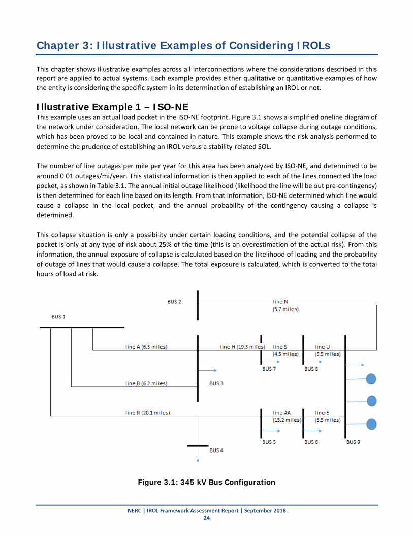
NERC | IROL Framework Assessment Report | September 2018 24
Chapter 3: Illustrative Examples of Considering IROLs This chapter shows illustrative examples across all interconnections where the considerations described in this report are applied to actual systems. Each example provides either qualitative or quantitative examples of how the entity is considering the specific system in its determination of establishing an IROL or not. Illustrative Example 1 – ISO-NE This example uses an actual load pocket in the ISO-NE footprint. Figure 3.1 shows a simplified oneline diagram of the network under consideration. The local network can be prone to voltage collapse during outage conditions, which has been proved to be local and contained in nature. This example shows the risk analysis performed to determine the prudence of establishing an IROL versus a stability-related SOL. The number of line outages per mile per year for this area has been analyzed by ISO-NE, and determined to be around 0.01 outages/mi/year. This statistical information is then applied to each of the lines connected the load pocket, as shown in Table 3.1. The annual initial outage likelihood (likelihood the line will be out pre-contingency) is then determined for each line based on its length. From that information, ISO-NE determined which line would cause a collapse in the local pocket, and the annual probability of the contingency causing a collapse is determined. This collapse situation is only a possibility under certain loading conditions, and the potential collapse of the pocket is only at any type of risk about 25% of the time (this is an overestimation of the actual risk). From this information, the annual exposure of collapse is calculated based on the likelihood of loading and the probability of outage of lines that would cause a collapse. The total exposure is calculated, which is converted to the total hours of load at risk.
Figure 3.1: 345 kV Bus Configuration

Chapter 3: Illustrative Examples of Considering IROLs
NERC | IROL Framework Assessment Report | September 2018 25
Table 3.1: ISO-NE Quantitative Outage Example
Line Length Annual Initial Outage Likelihood
Line Causing Collapse
Annual Probability of Outage Causing Collapse
Likelihood at Load Level with Exposure
Annual Exposure
A 6.3 6.30% N 5.70% 25.00% 0.090% B 6.2 6.20% N 5.70% 25.00% 0.088% R 20.1 20.10% N 5.70% 25.00% 0.286% H 19.3 19.30% N 5.70% 25.00% 0.275% S 4.5 4.50% N 5.70% 25.00% 0.064% AA 19.2 19.20% N 5.70% 25.00% 0.274% U 5.5 5.50% N 5.70% 25.00% 0.078% E 5.5 5.50% N 5.70% 25.00% 0.078% N 5.7 5.70% R 20.10% 40.00% 0.458%
Total Exposure (w/ No Gen Use) 1.692% Total Annual Hourly Exposure 148.2
Based on this information, the following comparison is made between the following scenarios:
1. An IROL is established and load must be shed pre-contingency to mitigate the contained5 voltage instability from occurring. (i.e., Framework B)
2. A stability-related SOL is established and load is not shed pre-contingency; there is some load at risk of voltage instability in the local load pocket. Realistic outage information is used. (i.e., Framework A)
3. A stability-related SOL is established and load is not shed pre-contingency; there is some load at risk of voltage instability in the local load pocket. Conservative outage information is used. (i.e., Framework A)
The following three examples using the scenarios listed above illustrate how it is not prudent to address this local voltage instability with the establishment of an IROL and pre-contingency load shedding required by Framework B. Rather, the issue should be addressed with a stability-related SOL that uses all available mitigating actions to eliminate the SOL exceedance (except pre-contingency load shedding) as allowed by the MEITF recommended Framework A. The amount of unserved energy to the load pocket is orders of magnitude higher when an IROL is established compared with the situations where a stability-related SOL is established to protect the load pocket. Example A: Realistic Comparison Assume that the following information is used to statistically compare the amount of annual energy loss between the establishment of an IROL (#1 above) and establishment of an SOL (#2 above) using realistic data (see Table 3.2). In this case, it is assumed that the amount of pre-contingency load shedding required to remain below the IROL is 30 MW on average. In this example, the generation in the load pocket is not available (e.g., has been recently retired) – therefore, generation redispatch is not considered in this case. The restoration time if voltage collapse occurs is 3 hours. The load at risk of collapsing is 160 MW.
5 The voltage instability was proved with detailed studies to be contained to a local area of approximately 160 MW of load at risk.
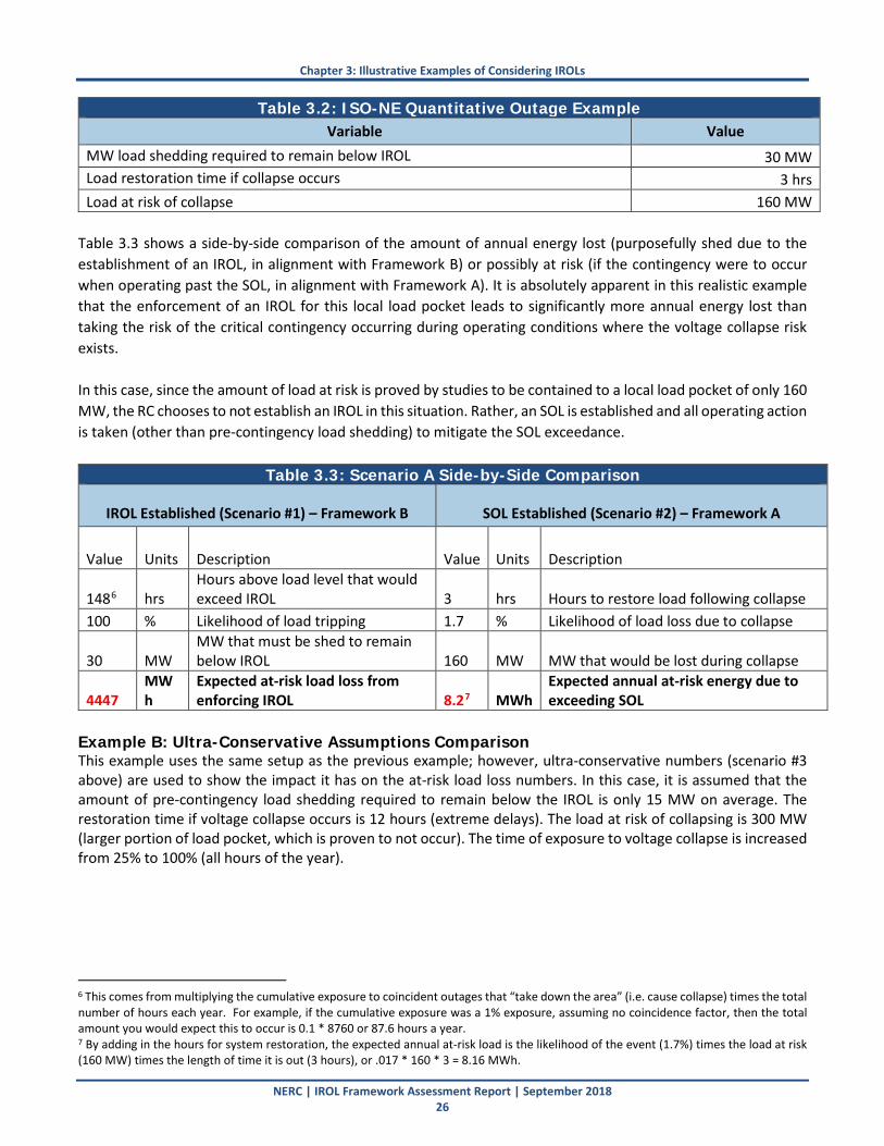
Chapter 3: Illustrative Examples of Considering IROLs
NERC | IROL Framework Assessment Report | September 2018 26
Table 3.2: ISO-NE Quantitative Outage Example Variable Value
MW load shedding required to remain below IROL 30 MW Load restoration time if collapse occurs 3 hrs Load at risk of collapse 160 MW
Table 3.3 shows a side-by-side comparison of the amount of annual energy lost (purposefully shed due to the establishment of an IROL, in alignment with Framework B) or possibly at risk (if the contingency were to occur when operating past the SOL, in alignment with Framework A). It is absolutely apparent in this realistic example that the enforcement of an IROL for this local load pocket leads to significantly more annual energy lost than taking the risk of the critical contingency occurring during operating conditions where the voltage collapse risk exists. In this case, since the amount of load at risk is proved by studies to be contained to a local load pocket of only 160 MW, the RC chooses to not establish an IROL in this situation. Rather, an SOL is established and all operating action is taken (other than pre-contingency load shedding) to mitigate the SOL exceedance.
Table 3.3: Scenario A Side-by-Side Comparison
IROL Established (Scenario #1) – Framework B SOL Established (Scenario #2) – Framework A
Value Units Description Value Units Description
1486 hrs Hours above load level that would exceed IROL 3 hrs Hours to restore load following collapse
100 % Likelihood of load tripping 1.7 % Likelihood of load loss due to collapse
30 MW MW that must be shed to remain below IROL 160 MW MW that would be lost during collapse
4447 MWh
Expected at-risk load loss from enforcing IROL 8.27 MWh
Expected annual at-risk energy due to exceeding SOL
Example B: Ultra-Conservative Assumptions Comparison This example uses the same setup as the previous example; however, ultra-conservative numbers (scenario #3 above) are used to show the impact it has on the at-risk load loss numbers. In this case, it is assumed that the amount of pre-contingency load shedding required to remain below the IROL is only 15 MW on average. The restoration time if voltage collapse occurs is 12 hours (extreme delays). The load at risk of collapsing is 300 MW (larger portion of load pocket, which is proven to not occur). The time of exposure to voltage collapse is increased from 25% to 100% (all hours of the year).
6 This comes from multiplying the cumulative exposure to coincident outages that “take down the area” (i.e. cause collapse) times the total number of hours each year. For example, if the cumulative exposure was a 1% exposure, assuming no coincidence factor, then the total amount you would expect this to occur is 0.1 * 8760 or 87.6 hours a year. 7 By adding in the hours for system restoration, the expected annual at-risk load is the likelihood of the event (1.7%) times the load at risk (160 MW) times the length of time it is out (3 hours), or .017 * 160 * 3 = 8.16 MWh.

Chapter 3: Illustrative Examples of Considering IROLs
NERC | IROL Framework Assessment Report | September 2018 27
Table 3.4: ISO-NE Quantitative Outage Example Variable Value
MW load shedding required to remain below IROL 15 MW Load restoration time if collapse occurs 12 hrs Load at risk of collapse 300 MW Number of line outages per mile per year 0.3 Likelihood at Load Level with Exposure 100%
With these assumptions, the likelihood of the collapse occurring increases to 6.1%. Table 3.5 shows again that establishing an IROL to protect against the local, contained voltage instability is not the prudent or reliable operating decision. In this case, even with conservative assumptions on the load restoration time, the probability of collapse occurring, and the impacted load pocket, the expected annual at-risk energy is an order of magnitude lower when a stability-related SOL is established compared with establishing an IROL. This is ultimately due to the fact that the IROL locks in pre-contingency load shedding for many hours of the year. Even though the amount of load shedding is relatively small, the frequency that this must occur is significant.
Table 3.5: Scenario A Side-by-Side Comparison
IROL Established (Scenario #1) – Framework B SOL Established (Scenario #2) – Framework A
Value Units Description Value Units Description
533 hrs Hours above load level that would exceed IROL 12 hrs
Hours to restore load following collapse
100 % Likelihood of load tripping 6.1 % Likelihood of load loss due to collapse
15 MW MW that must be shed to remain below IROL 300 MW MW that would be lost during collapse
7992 MWh Expected annual at-risk energy from enforcing IROL 219 MWh
Expected annual at-risk energy due to exceeding SOL
Example C: Realistic Comparison with Generation Redispatch Let us again use the Example A realistic data obtained by the RC, except this time consider generation redispatch for mitigating the hours in which the IROL exceedance would occur. In this case, the local generation in the load pocket is assumed to be able to ramp up within 30 minutes (an optimistic assumption in some cases) to eliminate the IROL exceedance and eliminate the need for pre-contingency load shedding. Let us also assume that this results in the need for pre-contingency load shedding only 15 hours out of the year, as opposed to the 148 hours calculated using the outage probabilities. As in, about 90% of the time that the IROL is exceeded, generation redispatch can address the exceedance. Table 3.6 shows the results of this comparison, and even in this case it is still not prudent to establish an IROL since it will result in about 20 times more energy being unserved compared to establishing an SOL and taking the risk of local voltage instability (proved to be contained).
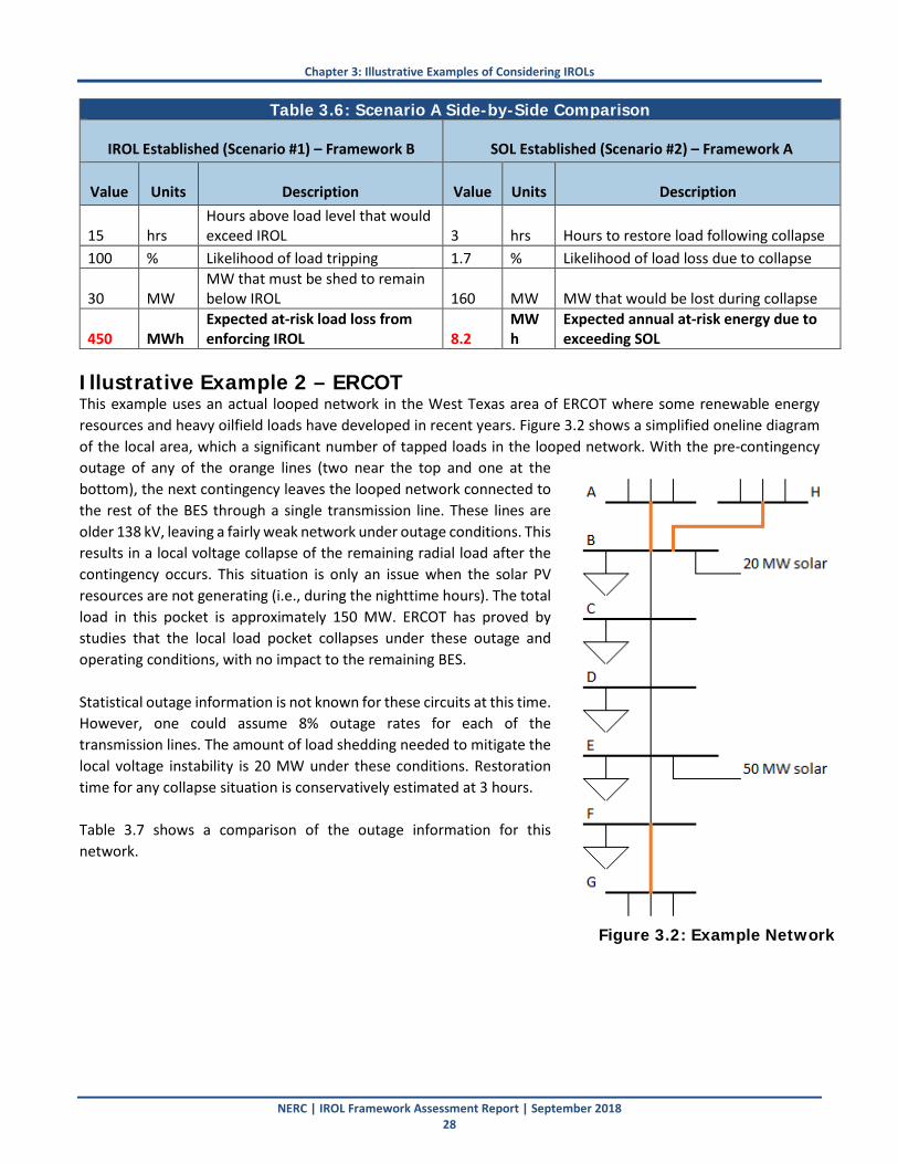
Chapter 3: Illustrative Examples of Considering IROLs
NERC | IROL Framework Assessment Report | September 2018 28
Table 3.6: Scenario A Side-by-Side Comparison
IROL Established (Scenario #1) – Framework B SOL Established (Scenario #2) – Framework A
Value Units Description Value Units Description
15 hrs Hours above load level that would exceed IROL 3 hrs Hours to restore load following collapse
100 % Likelihood of load tripping 1.7 % Likelihood of load loss due to collapse
30 MW MW that must be shed to remain below IROL 160 MW MW that would be lost during collapse
450 MWh Expected at-risk load loss from enforcing IROL 8.2
MWh
Expected annual at-risk energy due to exceeding SOL
Illustrative Example 2 – ERCOT This example uses an actual looped network in the West Texas area of ERCOT where some renewable energy resources and heavy oilfield loads have developed in recent years. Figure 3.2 shows a simplified oneline diagram of the local area, which a significant number of tapped loads in the looped network. With the pre-contingency outage of any of the orange lines (two near the top and one at the bottom), the next contingency leaves the looped network connected to the rest of the BES through a single transmission line. These lines are older 138 kV, leaving a fairly weak network under outage conditions. This results in a local voltage collapse of the remaining radial load after the contingency occurs. This situation is only an issue when the solar PV resources are not generating (i.e., during the nighttime hours). The total load in this pocket is approximately 150 MW. ERCOT has proved by studies that the local load pocket collapses under these outage and operating conditions, with no impact to the remaining BES. Statistical outage information is not known for these circuits at this time. However, one could assume 8% outage rates for each of the transmission lines. The amount of load shedding needed to mitigate the local voltage instability is 20 MW under these conditions. Restoration time for any collapse situation is conservatively estimated at 3 hours. Table 3.7 shows a comparison of the outage information for this network.
Figure 3.2: Example Network
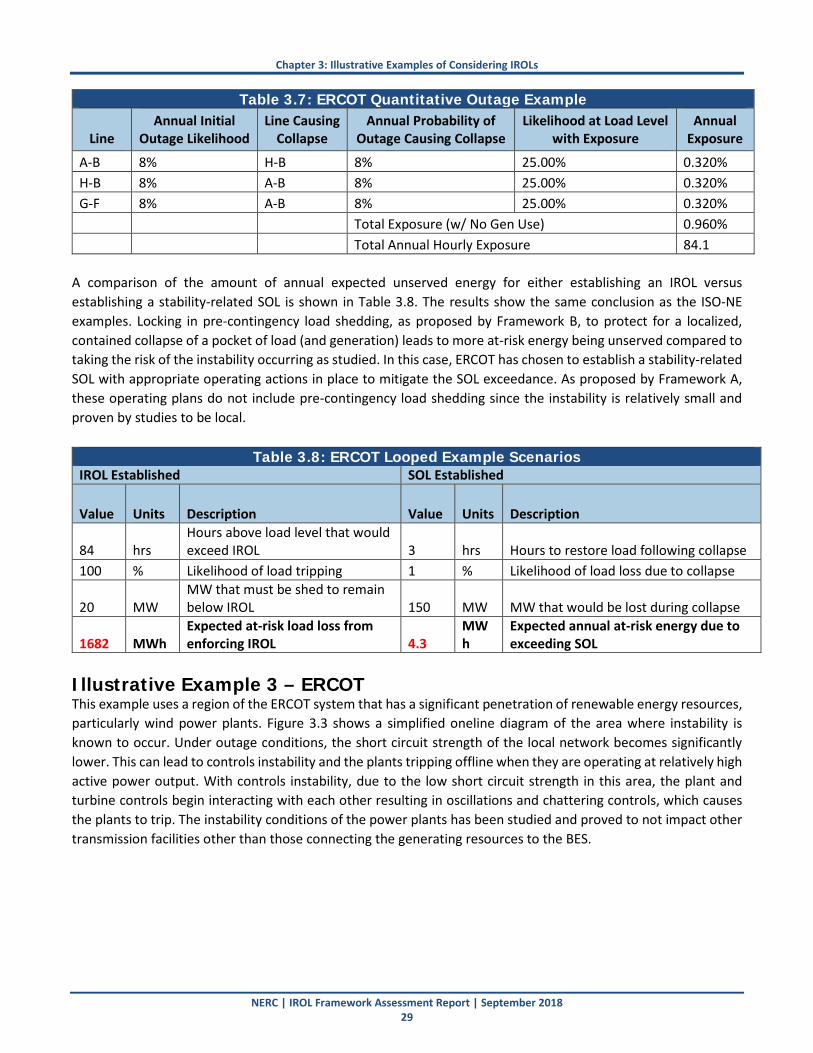
Chapter 3: Illustrative Examples of Considering IROLs
NERC | IROL Framework Assessment Report | September 2018 29
Table 3.7: ERCOT Quantitative Outage Example
Line Annual Initial
Outage Likelihood Line Causing
Collapse Annual Probability of
Outage Causing Collapse Likelihood at Load Level
with Exposure Annual
Exposure
A-B 8% H-B 8% 25.00% 0.320% H-B 8% A-B 8% 25.00% 0.320% G-F 8% A-B 8% 25.00% 0.320% Total Exposure (w/ No Gen Use) 0.960% Total Annual Hourly Exposure 84.1
A comparison of the amount of annual expected unserved energy for either establishing an IROL versus establishing a stability-related SOL is shown in Table 3.8. The results show the same conclusion as the ISO-NE examples. Locking in pre-contingency load shedding, as proposed by Framework B, to protect for a localized, contained collapse of a pocket of load (and generation) leads to more at-risk energy being unserved compared to taking the risk of the instability occurring as studied. In this case, ERCOT has chosen to establish a stability-related SOL with appropriate operating actions in place to mitigate the SOL exceedance. As proposed by Framework A, these operating plans do not include pre-contingency load shedding since the instability is relatively small and proven by studies to be local.
Table 3.8: ERCOT Looped Example Scenarios IROL Established SOL Established
Value Units Description Value Units Description
84 hrs Hours above load level that would exceed IROL 3 hrs Hours to restore load following collapse
100 % Likelihood of load tripping 1 % Likelihood of load loss due to collapse
20 MW MW that must be shed to remain below IROL 150 MW MW that would be lost during collapse
1682 MWh Expected at-risk load loss from enforcing IROL 4.3
MWh
Expected annual at-risk energy due to exceeding SOL
Illustrative Example 3 – ERCOT This example uses a region of the ERCOT system that has a significant penetration of renewable energy resources, particularly wind power plants. Figure 3.3 shows a simplified oneline diagram of the area where instability is known to occur. Under outage conditions, the short circuit strength of the local network becomes significantly lower. This can lead to controls instability and the plants tripping offline when they are operating at relatively high active power output. With controls instability, due to the low short circuit strength in this area, the plant and turbine controls begin interacting with each other resulting in oscillations and chattering controls, which causes the plants to trip. The instability conditions of the power plants has been studied and proved to not impact other transmission facilities other than those connecting the generating resources to the BES.
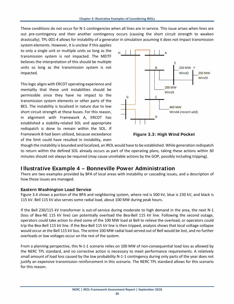
Chapter 3: Illustrative Examples of Considering IROLs
NERC | IROL Framework Assessment Report | September 2018 30
These conditions do not occur for N-1 contingencies when all lines are in service. This issue arises when lines are out pre-contingency and then another contingency occurs (causing the short circuit strength to weaken drastically). TPL-001-4 allows for instability of a generator in simulation assuming it does not impact transmission system elements. However, it is unclear if this applies to only a single unit or multiple units so long as the transmission system is not impacted. The MEITF believes the interpretation of this should be multiple units so long as the transmission system is not impacted. This logic aligns with ERCOT operating experience and mentality that these unit instabilities should be permissible since they have no impact to the transmission system elements or other parts of the BES. The instability is localized in nature due to low short circuit strength at these buses. For this reason, in alignment with Framework A, ERCOT has established a stability-related SOL and appropriate redispatch is done to remain within the SOL. If Framework B had been utilized, because exceedance of the limit could have resulted in instability, even though the instability is bounded and localized, an IROL would have to be established. While generation redispatch to return within the defined SOL already occurs as part of the operating plans, taking these actions within 30 minutes should not always be required (may cause unreliable actions by the GOP, possibly including tripping).
Illustrative Example 4 – Bonneville Power Administration There are two examples provided by BPA of local areas with instability or cascading issues, and a description of how those issues are managed. Eastern Washington Load Service Figure 3.4 shows a portion of the BPA and neighboring system, where red is 500 kV, blue is 230 kV, and black is 115 kV. Bell 115 kV also serves some radial load, about 100 MW during peak hours. If the Bell 230/115 kV transformer is out-of-service during moderate to high demand in the area, the next N-1 (loss of Bea-NE 115 kV line) can potentially overload the Bea-Bell 115 kV line. Following the second outage, operators could take action to shed some of the 100 MW load at Bell to relieve the overload, or operators could trip the Bea-Bell 115 kV line. If the Bea-Bell 115 kV line is then tripped, analysis shows that local voltage collapse would occur at the Bell 115 kV bus. The entire 100 MW radial load served out of Bell would be lost, and no further overloads or low voltages occur on the rest of the system. From a planning perspective, this N-1-1 scenario relies on 100 MW of non-consequential load loss as allowed by the NERC TPL standard, and no corrective action is necessary to meet performance requirements. A relatively small amount of load loss caused by the low probability N-1-1 contingency during only parts of the year does not justify an expensive transmission reinforcement in this scenario. The NERC TPL standard allows for this scenario for this reason.
Figure 3.3: High Wind Pocket
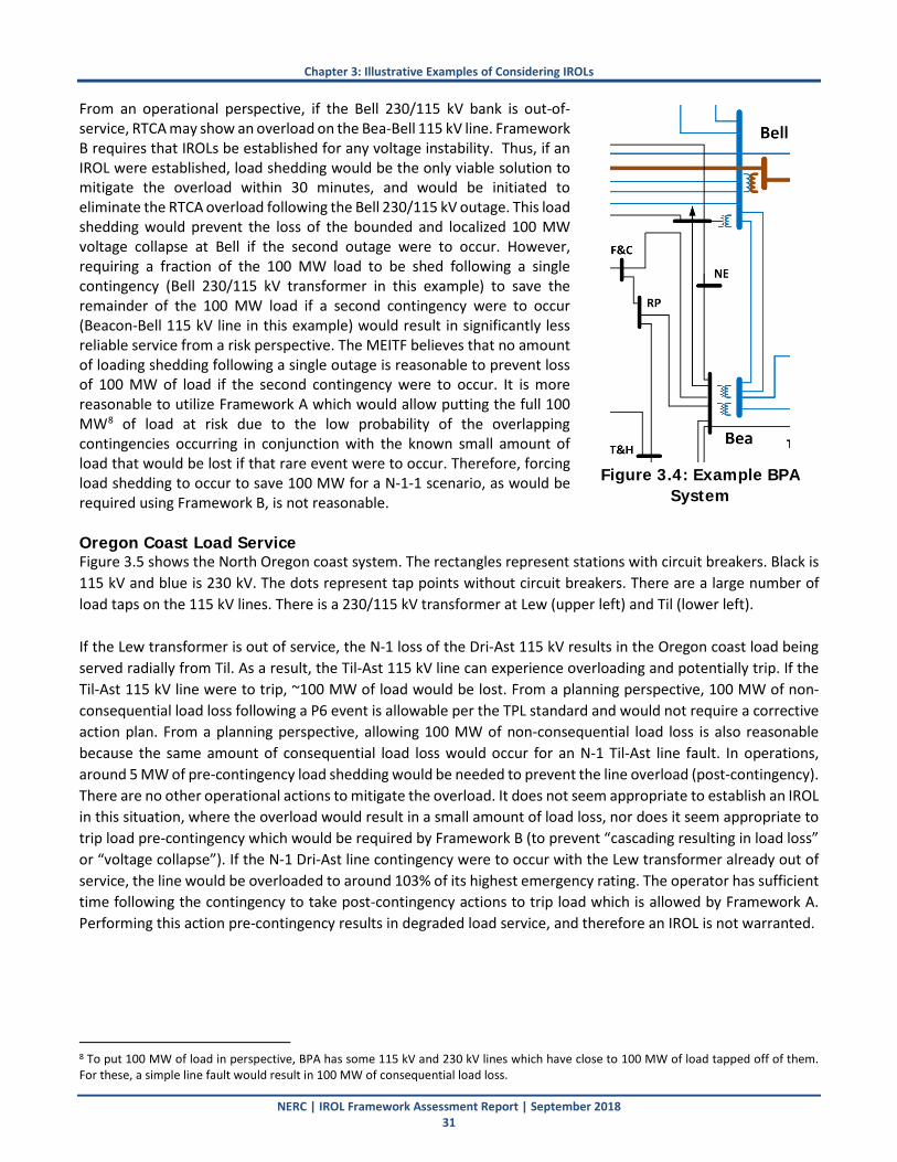
Chapter 3: Illustrative Examples of Considering IROLs
NERC | IROL Framework Assessment Report | September 2018 31
From an operational perspective, if the Bell 230/115 kV bank is out-of-service, RTCA may show an overload on the Bea-Bell 115 kV line. Framework B requires that IROLs be established for any voltage instability. Thus, if an IROL were established, load shedding would be the only viable solution to mitigate the overload within 30 minutes, and would be initiated to eliminate the RTCA overload following the Bell 230/115 kV outage. This load shedding would prevent the loss of the bounded and localized 100 MW voltage collapse at Bell if the second outage were to occur. However, requiring a fraction of the 100 MW load to be shed following a single contingency (Bell 230/115 kV transformer in this example) to save the remainder of the 100 MW load if a second contingency were to occur (Beacon-Bell 115 kV line in this example) would result in significantly less reliable service from a risk perspective. The MEITF believes that no amount of loading shedding following a single outage is reasonable to prevent loss of 100 MW of load if the second contingency were to occur. It is more reasonable to utilize Framework A which would allow putting the full 100 MW8 of load at risk due to the low probability of the overlapping contingencies occurring in conjunction with the known small amount of load that would be lost if that rare event were to occur. Therefore, forcing load shedding to occur to save 100 MW for a N-1-1 scenario, as would be required using Framework B, is not reasonable. Oregon Coast Load Service Figure 3.5 shows the North Oregon coast system. The rectangles represent stations with circuit breakers. Black is 115 kV and blue is 230 kV. The dots represent tap points without circuit breakers. There are a large number of load taps on the 115 kV lines. There is a 230/115 kV transformer at Lew (upper left) and Til (lower left). If the Lew transformer is out of service, the N-1 loss of the Dri-Ast 115 kV results in the Oregon coast load being served radially from Til. As a result, the Til-Ast 115 kV line can experience overloading and potentially trip. If the Til-Ast 115 kV line were to trip, ~100 MW of load would be lost. From a planning perspective, 100 MW of non-consequential load loss following a P6 event is allowable per the TPL standard and would not require a corrective action plan. From a planning perspective, allowing 100 MW of non-consequential load loss is also reasonable because the same amount of consequential load loss would occur for an N-1 Til-Ast line fault. In operations, around 5 MW of pre-contingency load shedding would be needed to prevent the line overload (post-contingency). There are no other operational actions to mitigate the overload. It does not seem appropriate to establish an IROL in this situation, where the overload would result in a small amount of load loss, nor does it seem appropriate to trip load pre-contingency which would be required by Framework B (to prevent “cascading resulting in load loss” or “voltage collapse”). If the N-1 Dri-Ast line contingency were to occur with the Lew transformer already out of service, the line would be overloaded to around 103% of its highest emergency rating. The operator has sufficient time following the contingency to take post-contingency actions to trip load which is allowed by Framework A. Performing this action pre-contingency results in degraded load service, and therefore an IROL is not warranted.
8 To put 100 MW of load in perspective, BPA has some 115 kV and 230 kV lines which have close to 100 MW of load tapped off of them. For these, a simple line fault would result in 100 MW of consequential load loss.
Figure 3.4: Example BPA
System
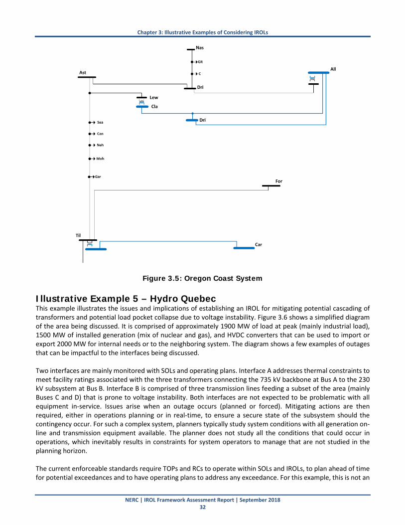
Chapter 3: Illustrative Examples of Considering IROLs
NERC | IROL Framework Assessment Report | September 2018 32
Figure 3.5: Oregon Coast System
Illustrative Example 5 – Hydro Quebec This example illustrates the issues and implications of establishing an IROL for mitigating potential cascading of transformers and potential load pocket collapse due to voltage instability. Figure 3.6 shows a simplified diagram of the area being discussed. It is comprised of approximately 1900 MW of load at peak (mainly industrial load), 1500 MW of installed generation (mix of nuclear and gas), and HVDC converters that can be used to import or export 2000 MW for internal needs or to the neighboring system. The diagram shows a few examples of outages that can be impactful to the interfaces being discussed. Two interfaces are mainly monitored with SOLs and operating plans. Interface A addresses thermal constraints to meet facility ratings associated with the three transformers connecting the 735 kV backbone at Bus A to the 230 kV subsystem at Bus B. Interface B is comprised of three transmission lines feeding a subset of the area (mainly Buses C and D) that is prone to voltage instability. Both interfaces are not expected to be problematic with all equipment in-service. Issues arise when an outage occurs (planned or forced). Mitigating actions are then required, either in operations planning or in real-time, to ensure a secure state of the subsystem should the contingency occur. For such a complex system, planners typically study system conditions with all generation on-line and transmission equipment available. The planner does not study all the conditions that could occur in operations, which inevitably results in constraints for system operators to manage that are not studied in the planning horizon. The current enforceable standards require TOPs and RCs to operate within SOLs and IROLs, to plan ahead of time for potential exceedances and to have operating plans to address any exceedance. For this example, this is not an

Chapter 3: Illustrative Examples of Considering IROLs
NERC | IROL Framework Assessment Report | September 2018 33
issue and all procedures and means are in place to ensure reliability of the 735 kV backbone and limit any risk of outages within the subsystem. However, the question arises if the interfaces shown here warrants establishment of an IROL as proposed by the two frameworks being considered.
Figure 3.6: Hydro Quebec Example System Interface A (thermal) The limits applicable to interface A are studied ahead of real-time and post-contingency analysis is performed though RTCA to ensure that the applicable facility ratings for the transformers are met. For the transmission planner, P1 contingencies (N-1) are not an issue, and P6 (N-1-1) are addressed with the allowable load shedding and system adjustments (that may or may not be aligned with the reality of operating constraints). Therefore, for planned and expected system conditions, transfers will be limited, generation will be committed, or outages will be denied to ensure that the next single contingency will not result in exceeding the SOL linked to that interface (i.e. exceeding the facility ratings of the transformers, the highest being 1500 MW). For example, if an outage needs to be scheduled on one transformer, the impact of the next N-1 contingency will be assessed and operations planning studies will configure the system to operate within the required SOLs. Here is a description of a typical sequence of events managed through operating plans that would otherwise be problematic if forced to establish an IROL:
• Initial condition : 3 transformers in service, 2430 MW transfer (1900 MW of internal load plus internal generation and HVDC export), 3000 MW post-contingency limit (post-contingency emergency rating of 2 remaining transformers)
• Some units at Bus G are unavailable due to planned outages and HVDC transfers are committed
• One transformer trips (forced outage)
• New limit calculated by RTCA: 1500 MW, operating alarm to proceed with system adjustments
400 MW600 MW 500 MW
Interface B (voltage)
HVDC converters (0-2000 MW inbound or outbound)
120 kV
230 kV
735 kV
735 kV backbone
Interface A (thermal)
400 MW
400 MW 500 MW
A
600 MW
B
C
D E F
G H
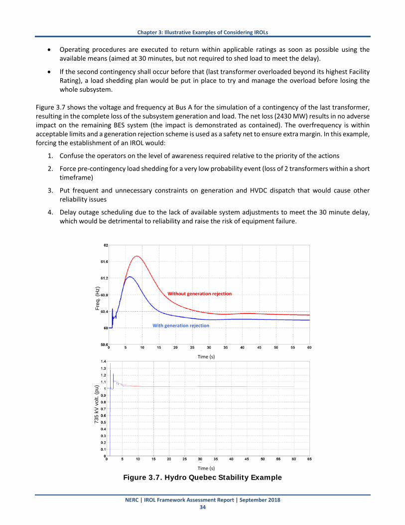
Chapter 3: Illustrative Examples of Considering IROLs
NERC | IROL Framework Assessment Report | September 2018 34
• Operating procedures are executed to return within applicable ratings as soon as possible using the available means (aimed at 30 minutes, but not required to shed load to meet the delay).
• If the second contingency shall occur before that (last transformer overloaded beyond its highest Facility Rating), a load shedding plan would be put in place to try and manage the overload before losing the whole subsystem.
Figure 3.7 shows the voltage and frequency at Bus A for the simulation of a contingency of the last transformer, resulting in the complete loss of the subsystem generation and load. The net loss (2430 MW) results in no adverse impact on the remaining BES system (the impact is demonstrated as contained). The overfrequency is within acceptable limits and a generation rejection scheme is used as a safety net to ensure extra margin. In this example, forcing the establishment of an IROL would:
1. Confuse the operators on the level of awareness required relative to the priority of the actions
2. Force pre-contingency load shedding for a very low probability event (loss of 2 transformers within a short timeframe)
3. Put frequent and unnecessary constraints on generation and HVDC dispatch that would cause other reliability issues
4. Delay outage scheduling due to the lack of available system adjustments to meet the 30 minute delay, which would be detrimental to reliability and raise the risk of equipment failure.
Figure 3.7. Hydro Quebec Stability Example
Time (s)
Time (s)
Freq
. (H
z)73
5 kV
vol
t. (p
u)
With generation rejection
Without generation rejection

Chapter 3: Illustrative Examples of Considering IROLs
NERC | IROL Framework Assessment Report | September 2018 35
According to IROL Framework B, any amount of load loss due to cascading warrants the establishment of an IROL. In this example, applying such a concept goes beyond what the system was planned for and is not warranted. On the other hand, Framework A provides the RC with flexibility to consider the cost of load loss, containment and bounding of any potential instability or cascading conditions, as well as the likelihood of occurrence. In this situation, the RC would balance the risks of the potential load loss versus the requirement to shed load pre-contingency in determining whether the cascading would be mitigated with an SOL or an IROL. In either case, the risk would be managed; however, Framework B drives the RC to manage that risk by shedding load pre-contingency. Interface B (voltage) Interface B is subject to voltage instability for mainly industrial customers with voltage-sensitive loads. The power transfer through this stability-related SOL depends on the available generating units, the status of the transmission lines, and the connected capacitors (mainly at Bus C). The fast voltage collapse can be easily demonstrated as contained with no impact outside of Buses C and D. Still, outages are carefully scheduled to meet the performance requirements with regards to the next N-1 contingency during real-time. Again, issues arise when an unplanned condition or forced outage occurs in real-time. One example would be a situation where a transmission line is scheduled for a long duration outage for which a significant delay is required to cancel the maintenance and bring the line back into service. All studies and procedures are then completed to configure the system properly and operate within SOLs. However, if during real-time operations an unexpected issue occurs with one generating unit (e.g., 600 MW at Bus G), this would result in an SOL exceedance (again, with an impact limited to voltage collapse affecting local load if the contingency were to occur). In this situation, procedures would require the availability of capacitors and commitment of other generating units to limit the transfer level on the interface and maximize voltage support. Similar to many local subsystems, the time required to proceed with those actions greater than 30 minutes. Forcing the establishment of an IROL with compliance obligations, urgency to act, and preventive load shedding does not make sense considering the likelihood of the N-1-1 event and its limited impact on system reliability. For such a case, the preparation of clear operating plans, with realistic steps to mitigate the SOL exceedance within a reasonable timeframe, is aligned with the current standards and industry practices to ensure an adequate level of reliability. Establishing an IROL would require more frequent and unnecessary load shedding of critical industrial customers who would rather tolerate the low risk of complete loss rather than being shed before the contingency actually happened. Again, Framework B in this case would drive the RC to pre-contingency load shedding to mitigate the local voltage instability that is proved to be contained to a load pocket. Framework A would give the RC flexibility in using a stability-related SOL (rather than an IROL) if the instability was of relatively small impact to the overall BES and proven to be contained via studies.
Illustrative Example 6 – ISO-NE This example shows two power plants connected to the same 345 kV breaker-and-a-half bus configuration (see Figure 3.8). With all lines in service, there are no restrictions to generation output. However, under outage conditions, there is a risk to unit(s) angular instability requiring the establishment of an SOL (or IROL). Figure 3.8 (right) shows the bus configuration when one breaker (red) is out of service pre-contingency, and another breaker becomes stuck during clearing (yellow). This puts the output of both plants on the 115 kV system, causing instability of both plants. To mitigate this instability, a 150 MW reduction in output is needed. This can be achieved by either (i) ramping one or both units or (ii) tripping a unit. The question becomes whether the SOL should be
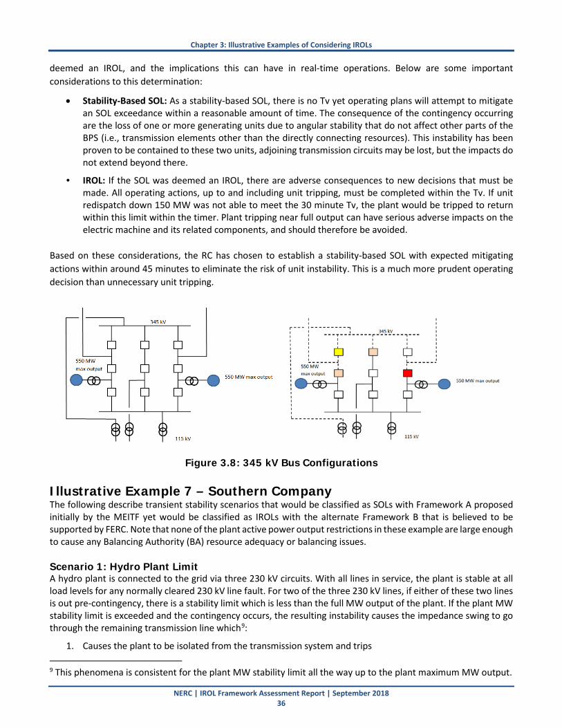
Chapter 3: Illustrative Examples of Considering IROLs
NERC | IROL Framework Assessment Report | September 2018 36
deemed an IROL, and the implications this can have in real-time operations. Below are some important considerations to this determination:
• Stability-Based SOL: As a stability-based SOL, there is no Tv yet operating plans will attempt to mitigate an SOL exceedance within a reasonable amount of time. The consequence of the contingency occurring are the loss of one or more generating units due to angular stability that do not affect other parts of the BPS (i.e., transmission elements other than the directly connecting resources). This instability has been proven to be contained to these two units, adjoining transmission circuits may be lost, but the impacts do not extend beyond there.
• IROL: If the SOL was deemed an IROL, there are adverse consequences to new decisions that must be made. All operating actions, up to and including unit tripping, must be completed within the Tv. If unit redispatch down 150 MW was not able to meet the 30 minute Tv, the plant would be tripped to return within this limit within the timer. Plant tripping near full output can have serious adverse impacts on the electric machine and its related components, and should therefore be avoided.
Based on these considerations, the RC has chosen to establish a stability-based SOL with expected mitigating actions within around 45 minutes to eliminate the risk of unit instability. This is a much more prudent operating decision than unnecessary unit tripping.
Figure 3.8: 345 kV Bus Configurations
Illustrative Example 7 – Southern Company The following describe transient stability scenarios that would be classified as SOLs with Framework A proposed initially by the MEITF yet would be classified as IROLs with the alternate Framework B that is believed to be supported by FERC. Note that none of the plant active power output restrictions in these example are large enough to cause any Balancing Authority (BA) resource adequacy or balancing issues. Scenario 1: Hydro Plant Limit A hydro plant is connected to the grid via three 230 kV circuits. With all lines in service, the plant is stable at all load levels for any normally cleared 230 kV line fault. For two of the three 230 kV lines, if either of these two lines is out pre-contingency, there is a stability limit which is less than the full MW output of the plant. If the plant MW stability limit is exceeded and the contingency occurs, the resulting instability causes the impedance swing to go through the remaining transmission line which9:
1. Causes the plant to be isolated from the transmission system and trips 9 This phenomena is consistent for the plant MW stability limit all the way up to the plant maximum MW output.
Chapter 3: Illustrative Examples of Considering IROLs
NERC | IROL Framework Assessment Report | September 2018 37
2. The only “load” lost is the hydro plant’s running station service The question becomes whether this stability limit should be an IROL or a stability-related SOL. If the limit becomes an IROL, then the RC must direct the GOP to reduce plant output to within the stability limit within 30 minutes (the Tv). Note that is the action that will be taken, as the Southeastern RC requires that SOLs be honored within 30 minutes. However, if the limit is a stability-related SOL, then the RC has the option of developing an operating plan to address the instability which could take longer than 30 minutes. Again the question becomes whether it is necessary or prudent to restrict plant output when it is known and studied that the resulting instability will only affect the plant itself, causing it to trip itself off-line. With the framework believed to be supported by FERC, this would have to be classified as an IROL (for no apparent reliability reason) since the impedance swing enters into a transmission element outside the design zone of protection. However, the resulting outcome does not result in customer load loss nor does the exceedance of the limit coupled with the contingency does not put the interconnection in any type of risk. As such, per the MEITF proposed Framework A, a stability-related SOL would be established rather than an IROL.
Scenario 2: Steam Plant A steam plant is interconnected to the grid via multiple 230 kV lines. With all lines in service and for the outage of one 230 kV line, the plant is stable at all load levels for any normally cleared 230 kV line fault. If a particular second 230 kV circuit is out of service, a stability limit exists that is less than the full MW output of the plant. If the new plant MW stability limit is exceeded by less than 90 MW and the worse contingency occurs, the resulting instability does not include an impedance swing that trips any additional transmission elements. If the new plant MW stability limit is exceeded by 90 MW up to maximum output of the plant and the worse contingency occurs, the resulting instability causes the impedance swing to go through two transmission elements but does not cause any load trip or unit isolation. The plant will be subject to a stability limit(s) if there are two certain lines out of service. The only question is if the limit(s) is a stability-related SOL or an IROL. Again, if Framework B, believed to be supported by FERC were adopted, this unit would have an SOL at one operating point and an IROL beyond that operating point. This is because at some plant active power outputs the impedance swing does not affect transmission elements and at higher outputs it does. However, in either case, the resulting transient instability is proved to have no impact on load loss nor negatively impact reliability of the larger BES. Currently, consistent with their SOL methodology and in alignment with the MEITF-proposed Framework A, Southern monitors and honors these stability limits during outage conditions using SOLs. Scenario 3: Hydro Plant Limit Another hydro plant is connected to the grid via three 230 kV circuits. With all lines in service, the plant is stable at all load levels for any normally cleared 230 kV line fault. For two of the three 230 kV lines, if either of these two transmission lines have a planned or unplanned outage, there is a stability limit that is less than the full MW output of the plant. If the new plant MW stability limit is exceeded by less than 70 MWs and the worse contingency occurs, the resulting instability does not include an impedance swing that trips any additional transmission Elements. If the new plant MW stability limit is exceeded by 70 MWs up to Pmax of the plant and the worse contingency occurs, the resulting instability causes the impedance swing to go through two transmission elements which causes the plant to be isolated from the BES and trips approximately 20 MW of load. Once again, if Framework B, believed to

Chapter 3: Illustrative Examples of Considering IROLs
NERC | IROL Framework Assessment Report | September 2018 38
be supported by FERC were adopted, this unit would have an SOL at one lower operating point, which is the limit that Southern would operate to, and an IROL beyond that operating point. Similar to the previous examples, establishing an IROL with mandatory action within 30 minutes (fairly tight for redispatching this plant) is not warranted by Southern since the outcome for the instability is nearly the same. The 20 MW of load lost during the instability event can be restored very quickly, in the rare occurrence where the contingency occurs with the line out of service already. The system is planned and operated around this local load service, and consistent with the MEITF-proposed Framework A, the instability is bounded and does not impacts BPS reliability and thus does warrant the establishment of an IROL.

NERC | IROL Framework Assessment Report | September 2018 39
Appendix A: Glossary of Terms and Acronyms Acronym/Term Definition BA Balancing Authority BES Bulk Electric System BPS Bulk Power System FERC Federal Energy Regulatory Commission GOP Generator Operator HVDC High Voltage Direct Current IROL Interconnection Reliability Operating Limit IROL Tv IROL Time Limit NERC North American Electric Reliability Corporation NERC MEITF NERC Methods for Establishing IROLs Task Force NERC OC NERC Operating Committee NERC PC NERC Planning Committee OPA Operational Planning Assessment RC Reliability Coordinator RTA Real-Time Assessment RTCA Real-Time Contingency Analysis SDT Standard Drafting Team SOL System Operating Limit TOP Transmission Operator
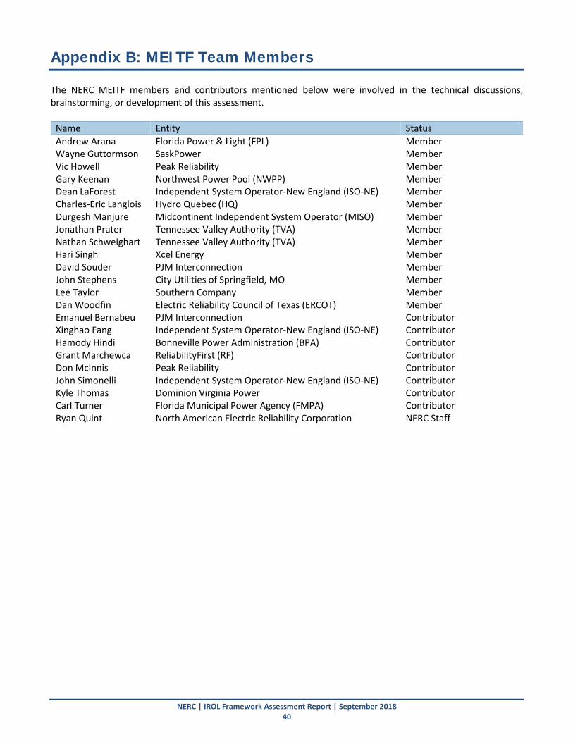
NERC | IROL Framework Assessment Report | September 2018 40
Appendix B: MEITF Team Members The NERC MEITF members and contributors mentioned below were involved in the technical discussions, brainstorming, or development of this assessment.
Name Entity Status Andrew Arana Florida Power & Light (FPL) Member Wayne Guttormson SaskPower Member Vic Howell Peak Reliability Member Gary Keenan Northwest Power Pool (NWPP) Member Dean LaForest Independent System Operator-New England (ISO-NE) Member Charles-Eric Langlois Hydro Quebec (HQ) Member Durgesh Manjure Midcontinent Independent System Operator (MISO) Member Jonathan Prater Tennessee Valley Authority (TVA) Member Nathan Schweighart Tennessee Valley Authority (TVA) Member Hari Singh Xcel Energy Member David Souder PJM Interconnection Member John Stephens City Utilities of Springfield, MO Member Lee Taylor Southern Company Member Dan Woodfin Electric Reliability Council of Texas (ERCOT) Member Emanuel Bernabeu PJM Interconnection Contributor Xinghao Fang Independent System Operator-New England (ISO-NE) Contributor Hamody Hindi Bonneville Power Administration (BPA) Contributor Grant Marchewca ReliabilityFirst (RF) Contributor Don McInnis Peak Reliability Contributor John Simonelli Independent System Operator-New England (ISO-NE) Contributor Kyle Thomas Dominion Virginia Power Contributor Carl Turner Florida Municipal Power Agency (FMPA) Contributor Ryan Quint North American Electric Reliability Corporation NERC Staff
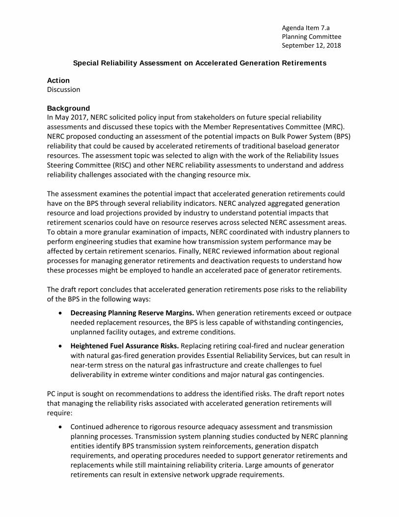
Agenda Item 7.a Planning Committee September 12, 2018
Special Reliability Assessment on Accelerated Generation Retirements
Action Discussion Background In May 2017, NERC solicited policy input from stakeholders on future special reliability assessments and discussed these topics with the Member Representatives Committee (MRC). NERC proposed conducting an assessment of the potential impacts on Bulk Power System (BPS) reliability that could be caused by accelerated retirements of traditional baseload generator resources. The assessment topic was selected to align with the work of the Reliability Issues Steering Committee (RISC) and other NERC reliability assessments to understand and address reliability challenges associated with the changing resource mix. The assessment examines the potential impact that accelerated generation retirements could have on the BPS through several reliability indicators. NERC analyzed aggregated generation resource and load projections provided by industry to understand potential impacts that retirement scenarios could have on resource reserves across selected NERC assessment areas. To obtain a more granular examination of impacts, NERC coordinated with industry planners to perform engineering studies that examine how transmission system performance may be affected by certain retirement scenarios. Finally, NERC reviewed information about regional processes for managing generator retirements and deactivation requests to understand how these processes might be employed to handle an accelerated pace of generator retirements. The draft report concludes that accelerated generation retirements pose risks to the reliability of the BPS in the following ways:
• Decreasing Planning Reserve Margins. When generation retirements exceed or outpace needed replacement resources, the BPS is less capable of withstanding contingencies, unplanned facility outages, and extreme conditions.
• Heightened Fuel Assurance Risks. Replacing retiring coal-fired and nuclear generation with natural gas-fired generation provides Essential Reliability Services, but can result in near-term stress on the natural gas infrastructure and create challenges to fuel deliverability in extreme winter conditions and major natural gas contingencies.
PC input is sought on recommendations to address the identified risks. The draft report notes that managing the reliability risks associated with accelerated generation retirements will require:
• Continued adherence to rigorous resource adequacy assessment and transmission planning processes. Transmission system planning studies conducted by NERC planning entities identify BPS transmission system reinforcements, generation dispatch requirements, and operating procedures needed to support generator retirements and replacements while still maintaining reliability criteria. Large amounts of generator retirements can result in extensive network upgrade requirements.
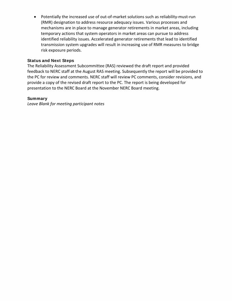
• Potentially the increased use of out-of-market solutions such as reliability-must-run (RMR) designation to address resource adequacy issues. Various processes and mechanisms are in place to manage generator retirements in market areas, including temporary actions that system operators in market areas can pursue to address identified reliability issues. Accelerated generator retirements that lead to identified transmission system upgrades will result in increasing use of RMR measures to bridge risk exposure periods.
Status and Next Steps The Reliability Assessment Subcommittee (RAS) reviewed the draft report and provided feedback to NERC staff at the August RAS meeting. Subsequently the report will be provided to the PC for review and comments. NERC staff will review PC comments, consider revisions, and provide a copy of the revised draft report to the PC. The report is being developed for presentation to the NERC Board at the November NERC Board meeting. Summary Leave Blank for meeting participant notes

Agenda Item 7.b Planning Committee September 12, 2018
2018 Long-Term Reliability Assessment Update
Action Discussion Background NERC is required by Section 215 of the Federal Power Act to conduct periodic assessments of the reliability and adequacy of the Bulk-Power System and to report findings annually. The 2018 Long-term Reliability Assessment (LTRA) is being developed to satisfy NERC’s obligations in accordance with NERC Rules of Procedure. This assessment i s developed based on data and narrative information collected by NERC from the Regional Entities on an assessment area basis to independently assess the long-term reliability of the North American BPS while identifying trends, emerging issues, and potential risks during the 10-year assessment period. The Reliability Assessment Subcommittee (RAS), at the direction of the PC, supports the development of this assessment through a comprehensive and transparent peer review process that leverages the knowledge and experience of system planners, RAS members, NERC staff, and other subject matter experts. During the PC meeting NERC Staff will provide an update on 2018 report development and discuss draft key findings. The report will be provided for PC review in late September. NERC staff will review comments and develop revisions as appropriate, and send the report to the PC for electronic vote for endorsement. The LTRA development schedule is posted here. Summary Leave Blank for meeting participant notes

Agenda Item 7.c Planning Committee September 12, 2018
System Planning Impacts from Distributed Energy Resources Subcommittee
(SPIDERS) Action Discussion Background The PC has been working throughout the year to identify reliability objectives related to a growing penetration of distributed energy resources (DER) that should be included within the activities of the PC. The PC leadership and NERC Staff held a DER working meeting following the PC meeting in March 2018 on this topic. Participants discussed reliability issues related to DER that they are observing or foresee, and shared views on priorities for addressing these issues. PC members reviewed these objectives and provided input on priorities at the June 2018 PC meeting and in a comment period that followed the meeting. During the PC Executive Committee (PCEC) web meeting on June 29, the PCEC supported establishing a group within the PC structure for Addressing identified DER Issues. PC leadership, NERC staff, and SPIDERS leaders will discuss next steps in establishing the group, including anticipated scope, work activities, and opportunities for stakeholders to participate. Summary Leave Blank for meeting participant notes