afp-400 us prog manual
TRANSCRIPT

$)3�����$)3����
$QDORJ�)LUH�3DQHOProgramming Manual
12 Clintonvill e RoadNorthford, CT 06472(203) 484-7161(203) 484-7118 (Fax)
'RFXPHQW������
�������� 5HYLVLRQ� C31 ������&� (&1 ������

WARNING: This equipment generates, uses, and can radiate radio frequencyenergy and if not installed and used in accordance with the instruction manual, maycause interference to radio communications. It has been tested and found to complywith the limits for class A computing device pursuant to Subpart B of Part 15 of FCCRules, which is designed to provide reasonable protection against such interferencewhen operated in a commercial environment. Operation of this equipment in aresidential area is likely to cause interference, in which case the user will be requiredto correct the interference at his own expense.
Installation Precautions - Adherence to the following will aid in problem-free installation with long-term reliability:
WARNING - Several different sources of power can be connected to the fire alarmcontrol panel. Disconnect all sources of power before servicing. Control unit andassociated equipment may be damaged by removing and/or inserting cards,modules, or interconnecting cables while the unit is energized. Do not attempt toinstall, service, or operate this unit until this manual is read and understood.
CAUTION - System Reacceptance Test after Software Changes: To ensureproper system operation, this product must be tested in accordance with NFPA 72-1993 Chapter 7 after any programming operation or change in site-specific software.Reacceptance testing is required after any change, addition or deletion of systemcomponents, or after any modification, repair or adjustment to system hardware orwiring.
All components, circuits, system operations, or software functions known to beaffected by a change must be 100% tested. In addition, to ensure that otheroperations are not inadvertently affected, at least 10% of initiating devices that arenot directly affected by the change, up to a maximum of 50 devices, must also betested and proper system operation verified.
This system meets NFPA requirements for operation at 0-49O C/32-120O Fand at a relative humidity of 85% RH (non-condensing) at 30O C/86O F.However, the useful life of the system's standby batteries and the electroniccomponents may be adversely affected by extreme temperature ranges andhumidity. Therefore, it is recommended that this system and its peripherals beinstalled in an environment with a nominal room temperature of 15-27O C/60-80O
F.
Verify that wire sizes are adequate for all initiating and indicating device loops.Most devices cannot tolerate more than a 10% I.R. drop from the specified devicevoltage.
Like all solid state electronic devices, this system may operate erratically or canbe damaged when subjected to lightning induced transients. Although no system iscompletely immune from lightning transients and interferences, proper grounding willreduce susceptibility. Overhead or outside aerial wiring is not recommended, due toan increased susceptibility to nearby lightning strikes. Consult with the TechnicalServices Department if any problems are anticipated or encountered.
Disconnect AC power and batteries prior to removing or inserting circuit boards.Failure to do so can damage circuits.
Remove all electronic assemblies prior to any drilling, filing, reaming, or punchingof the enclosure. When possible, make all cable entries from the sides or rear.Before making modifications, verify that they will not interfere with battery,transformer, and printed circuit board location.
Do not tighten screw terminals more than 9 in-lbs. Over tightening may damagethreads, resulting in reduced terminal contact pressure and difficulty with screwterminal removal.
This system contains static-sensitive components. Always ground yourself with aproper wrist strap before handling any circuits so that static charges are removedfrom the body. Use static suppressive packaging to protect electronic assembliesremoved from the unit.
Follow the instructions in the installation, operating, and programming manuals.These instructions must be followed to avoid damage to the control panel andassociated equipment. FACP operation and reliability depend upon properinstallation.
Fire Alarm System Limitations While installing a fire alarm system may make lower insurancerates possible, it is not a substitute for fire insurance!
An automatic fire alarm system - typically made up of smoke detectors, heatdetectors, manual pull stations, audible warning devices, and a fire alarm controlwith remote notification capability can provide early warning of a developing fire.Such a system, however, does not assure protection against property damage orloss of life resulting from a fire.
Any fire alarm system may fail for a variety of reasons:
Smoke detectors may not sense fire where smoke cannot reach the detectors suchas in chimneys, in walls, or roofs, or on the other side of closed doors. Smokedetectors also may not sense a fire on another level or floor of a building. A secondfloor detector, for example, may not sense a first floor or basement fire. Further-more, all types of smoke detectors - both ionization and photoelectric types, havesensing limitations. No type of smoke detector can sense every kind of fire causedby carelessness and safety hazards like smoking in bed, violent explosions,escaping gas, improper storage of flammable materials, overloaded electricalcircuits, children playing with matches, or arson.
IMPORTANT! Smoke detectors must be installed in the same room as thecontrol panel and in rooms used by the system for the connection of alarmtransmission wiring, communications, signaling, and/or power. If detectors arenot so located, a developing fire may damage the alarm system, crippling itsability to report a fire.
Audible warning devices such as bells may not alert people if these devices arelocated on the other side of closed or partly open doors or are located on anotherfloor of a building.
A fire alarm system will not operate without any electrical power. If AC power fails,the system will operate from standby batteries only for a specified time.
Rate-of-Rise heat detectors may be subject to reduced sensitivity over time. Forthis reason, the rate-of-rise feature of each detector should be tested at least onceper year by a qualified fire protection specialist.
Equipment used in the system may not be technically compatible with the control.It is essential to use only equipment listed for service with your control panel.
Telephone lines needed to transmit alarm signals from a premise to a centralmonitoring station may be out of service or temporarily disabled.
The most common cause of fire alarm malfunctions, however, is inadequatemaintenance. All devices and system wiring should be tested and maintained byprofessional fire alarm installers following written procedures supplied with eachdevice. System inspection and testing should be scheduled monthly or as requiredby National and/or local fire codes. Adequate written records of all inspections shouldbe kept.
FCC WarningCanadian RequirementsThis digital apparatus does not exceed the Class A limits for radiation noiseemissions from digital apparatus set out in the Radio Interference Regulations of theCanadian Department of Communications.
Le present appareil numerique n'emet pas de bruits radioelectriques depassant leslimites applicables aux appareils numeriques de la classe A prescrites dans leReglement sur le brouillage radioelectrique edicte par le ministere des Communica-tions du Canada.
Technical Publishing Document PRECAULG.P65 12/31/96

.............. 1...... 2.... 2..... 2.... 3..... 4.. 4
.......... 5...... 5...... 5.... 6..... 6.... 6.... 7...... 8..... 9.... 9..... 910. 101112
. 12. 13.. 13..... 14..... 14.... 15... 15... 15.... 16..... 16... 16... 17.. 17.. 17... 17.. 17... 18... 18.. 19.. 20...
... 21.... 21... 22.. 22
7DEOH�RI�&RQWHQWV
���,QWURGXFWLRQOverview ..................................................................................................................1Benefits....................................................................................................................... 1In This Chapter ........................................................................................................Conventions and Symbols .......................................................................................Entering Information from the Control Panel ...........................................................Using Programming Keys ........................................................................................Additional Information..............................................................................................Choosing a Programming Method............................................................................Veri•Fire Off-Line Programming Utility.....................................................................
���3URJUDP�&KDQJHOverview ..................................................................................................................5
Entering Program Change Mode .....................................................................Entering a Password........................................................................................Changing a Password......................................................................................
Clear Programming Information ...............................................................................Autoprogram.............................................................................................................
Displaying a Device..........................................................................................Autoprogramming Defaults ..............................................................................
System Defaults.......................................................................................................Point Programming...................................................................................................
Point Programming Overview ..........................................................................Programming a Detector ..................................................................................Programming a Monitor Module (MMX) ..........................................................MMX Default Zone Assignments......................................................................Type Codes for Monitor Modules (MMX).........................................................Programming a Control Module (CMX) ............................................................Type Codes for Control Modules (CMX)..........................................................Programming NAC/Panel Output Circuits ........................................................NAC/Panel Output Circuit Type Codes............................................................
Changing a Password .............................................................................................Changing the System Message...............................................................................Changing a Custom Label .......................................................................................
Rules for Changing a Custom Label................................................................How to Change a Custom Label ......................................................................
Special Zone Change...............................................................................................Special Function Screens........................................................................................
F0 (Presignal)...................................................................................................R0-R9 (Releasing Functions)...........................................................................F5-F6 (Time Control Functions).......................................................................F7 (Holiday)......................................................................................................F8 (Code Type) ................................................................................................F9 (Pre-Alarm)..................................................................................................
System Function Programming ................................................................................System Functions.............................................................................................Annunciator Options.........................................................................................ACS Selection Group Example ........................................................................
Check........................................................................................................................ 20
���6WDWXV�&KDQJHOverview ..................................................................................................................Disable/Enable.........................................................................................................Detector Sensitivity ..................................................................................................
Overview...........................................................................................................
AFP-300/AFP-400 Programming PN 50259:C1 06/19/97 iii

7DEOH RI &RQWHQWV Appendix A: Releasing Applications
... 22.. 22... 23... 23..... 23.... 2.. 24.. 24.. 24.. 25. 25.. 25
... 26
.... 26
.... 27
.. 27.. 27... 2829
... 29.. 30... 30. 30.. 30
.... 31... 31.. 31.. 31.. 32
.. 33... 33.. 33.. 34. 35.. 35.. 36... 36. 36. 36. 37... 38... 39. 39.. 40.... 41.. 41.. 41. 41... 42.. 42
How to Select a Detector .................................................................................Selecting Detector Sensitivity...........................................................................
Clear Verification Counters......................................................................................Clear the History File ...............................................................................................Set the System Time and Date................................................................................Walk Test.................................................................................................................4
Overview...........................................................................................................What the Control Panel Does in Walk Test ......................................................What to do Before Selecting Walk Test ...........................................................How to do a Walk Test .....................................................................................Entering and Exiting Walk Test Mode ..............................................................Finishing a Walk Test .......................................................................................
$SSHQGL[�$� 5HOHDVLQJ�$SSOLFDWLRQVOverview ..................................................................................................................NFPA Standards ......................................................................................................Programming a Releasing Zone ..............................................................................
Delay Timer ......................................................................................................Abort Timer ......................................................................................................Cross Zoning....................................................................................................Soak Timer (NFPA 16 Applications Only) ........................................................Special Module Types .....................................................................................Initiating Devices..............................................................................................Warning Sounders............................................................................................Auxiliary Control Functions ..............................................................................ACS Annunciation............................................................................................
$SSHQGL[�%��2XWSXWVPresignal and Positive Alarm Sequence (PAS) .......................................................
Presignal...........................................................................................................Positive Alarm Sequence (PAS) .......................................................................
Time Control .............................................................................................................NAC Coding..............................................................................................................
$SSHQGL[�&��$:$&6�$SSOLFDWLRQVAWACS Overview....................................................................................................AWACS Features .....................................................................................................
Drift Compensation and Smoothing .................................................................Maintenance Warnings – Three Levels ............................................................Self-Optimizing Pre-Alarm................................................................................Sensitivity Levels..............................................................................................Cooperating Multi-Detector Sensing ................................................................
Pre-Alarm .................................................................................................................Pre-Alarm Overview..........................................................................................Alert Level .........................................................................................................Action Level ......................................................................................................
Selecting a Pre-Alarm Level ....................................................................................Detector Sensitivity Settings ....................................................................................
Selecting Pre-Alarm and Alarm Sensitivity.......................................................Testing Detectors Set Below 0.50% .................................................................
Detector Maintenance Features ...............................................................................Overview...........................................................................................................Accessing Detector Maintenance Information..................................................Viewing Detector Maintenance for a Detector ..................................................Creating a Detector Maintenance Report.........................................................Interpreting a Detector Status Display or Maintenance Report ........................
iv AFP-300/AFP-400 Programming PN 50259:C1 06/19/97
el. by
re
ble
e
C;
���,QWURGXFWLRQ�
2YHUYLHZ
The AFP-300/AFP-400 is an intelligent, field-programmable Fire Alarm Control PanField-programming the AFP-300/AFP-400 lets you customize the fire alarm systemselecting and setting program options for output circuits, intelligent/addressable devices, Notification Appliance Circuits (NACs), and monitor/control modules.
%HQHILWV
Benefits of AFP-300/AFP-400 programming include the following:
• Ease-of-use – Field program the control panel without needing special softwaskills.
• Autoprogramming Function – Automatically detects newly installed, addressadevices, allowing quicker installation.
• Local programming – program directly from the control panel keypad to reducinstallation time.
• Remote programming – input long data entry programming information on a Ptransfer programming data between a PC and the control panel.
• Security – use passwords to control access to the control panel and protect memory.
• 80-Character (2x40) Liquid Crystal Display – view programming and device information on the control panel.
,Q�7KLV�&KDSWHU1RWH� 7KLV PDQXDO FRQWDLQV
LQIRUPDWLRQ IRU HQWHULQJ
SURJUDPPLQJ GDWD WR WKH
FRQWURO SDQHO XVLQJ
SURJUDPPLQJ NH\V RQ WKH IURQW
SDQHO� )RU GHWDLOV RQ FRQWURO
SDQHO RSHUDWLRQ� UHIHU WR WKH
$)3�����$)3���� 2SHUDWLRQV
0DQXDO�
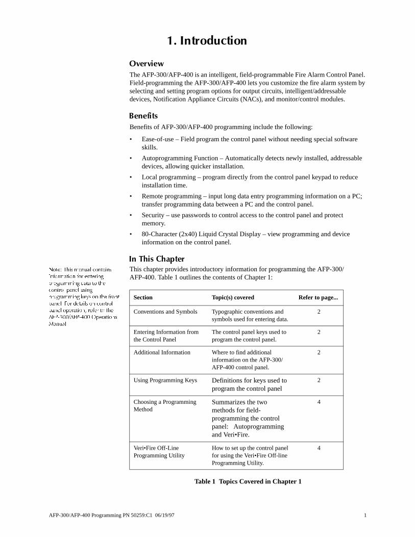
This chapter provides introductory information for programming the AFP-300/AFP-400. Table 1 outlines the contents of Chapter 1:
Table 1 Topics Covered in Chapter 1
Section Topic(s) covered Refer to page...
Conventions and Symbols Typographic conventions and symbols used for entering data.
2
Entering Information from the Control Panel
The control panel keys used to program the control panel.
2
Additional Information Where to find additional information on the AFP-300/AFP-400 control panel.
2
Using Programming Keys Definitions for keys used to program the control panel
2
Choosing a Programming Method
Summarizes the two methods for field-programming the control panel: Autoprogramming and Veri•Fire.
4
Veri•Fire Off-Line Programming Utility
How to set up the control panel for using the Veri•Fire Off-line Programming Utility.
4
AFP-300/AFP-400 Programming PN 50259:C1 06/19/97 1
�� ,QWURGXFWLRQ Conventions and Symbols
cters,
trol
&RQYHQWLRQV�DQG�6\PEROV
This manual uses conventions and symbols to provide the following types of information:
• Note – indicates supplementary information.
• Warning – indicates information about procedures that could cause error, programming errors, runtime errors, or equipment damage.
For presentation and printing purposes, this manual uses different typeface charain place of the actual LCD letters that you see on the panel display.
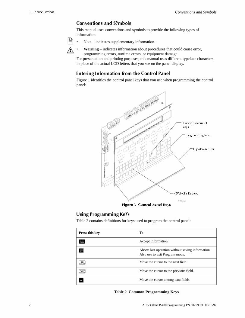
(QWHULQJ�,QIRUPDWLRQ�IURP�WKH�&RQWURO�3DQHO
Figure 1 identifies the control panel keys that you use when programming the conpanel:
)LJXUH � &RQWURO 3DQHO .H\V
8VLQJ�3URJUDPPLQJ�.H\V
Table 2 contains definitions for keys used to program the control panel:
Table 2 Common Programming Keys
�
3URJUDPPLQJ NH\V
4:(57< .H\SDG
&XUVRU PRYHPHQW
NH\V
)OLS�GRZQ GRRU
Press this key To
& Accept information.
6 Aborts last operation without saving information. Also use to exit Program mode.
/ Move the cursor to the next field.
0 Move the cursor to the previous field.
* Move the cursor among data fields.
2 AFP-300/AFP-400 Programming PN 50259:C1 06/19/97

Additional Information �� ,QWURGXFWLRQ
panel
This manual uses the following conventions for entering data and pressing control keys, as listed in Table 3:Table 3 Type Conventions
$GGLWLRQDO�,QIRUPDWLRQ
Table 4 contains a list of documents that contain additional information on the AFP-300/AFP-400:
Table 4 Additional Documentation
When you see Do this Example
<text in brackets> Type the text <1> means to type “1”
a graphic of the key Press the key 6 means to press the key
Document Title Document No.
Veri•Fire 400™ Off Line Programming Utility Product Installation Document
50376
AFP-300/AFP-400 Operations Manual 50260
AFP-300/AFP-400AFP-400 Installation Manual 50253
AFP-300/AFP-400 Programming PN 50259:C1 06/19/97 3
�� ,QWURGXFWLRQ Choosing a Programming Method
nel: the
ps in
).
&KRRVLQJ�D�3URJUDPPLQJ�0HWKRG
The AFP-300/AFP-400 provides two methods for field-programming the control pausing the Autoprogram feature or the Veri•Fire™ Programming Utility. Table 5 lists benefits of each method:
Table 5 Field-Programming Options
9HUL�)LUH 2II�/LQH 3URJUDPPLQJ 8WLOLW\
1RWH� )RU GHWDLOHG LQVWDOODWLRQ
RSHUDWLRQV LQVWUXFWLRQV� UHIHU WR�
WKH 9HUL�)LUH ��� 3URGXFWLRQ
,QVWDOODWLRQ 'RFXPHQW RU WKH
9HUL�)LUH RQOLQH KHOS ILOH�
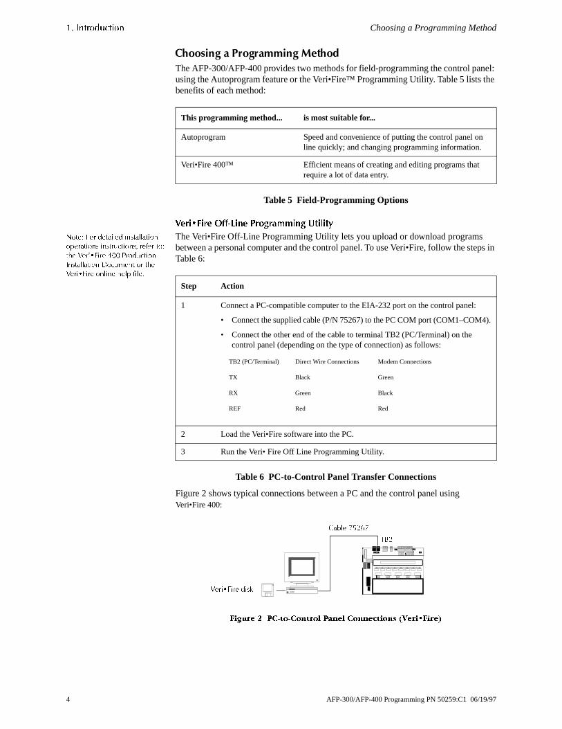
The Veri•Fire Off-Line Programming Utility lets you upload or download programs between a personal computer and the control panel. To use Veri•Fire, follow the steTable 6:
Table 6 PC-to-Control Panel Transfer Connections
Figure 2 shows typical connections between a PC and the control panel using Veri•Fire 400:
)LJXUH � 3&�WR�&RQWURO 3DQHO &RQQHFWLRQV �9HUL�)LUH�
This programming method... is most suitable for...
Autoprogram Speed and convenience of putting the control panel online quickly; and changing programming information.
Veri•Fire 400™ Efficient means of creating and editing programs that require a lot of data entry.
Step Action
1 Connect a PC-compatible computer to the EIA-232 port on the control panel:
• Connect the supplied cable (P/N 75267) to the PC COM port (COM1–COM4
• Connect the other end of the cable to terminal TB2 (PC/Terminal) on the control panel (depending on the type of connection) as follows:
2 Load the Veri•Fire software into the PC.
3 Run the Veri• Fire Off Line Programming Utility.
TB2 (PC/Terminal) Direct Wire Connections Modem Connections
TX Black Green
RX Green Black
REF Red Red
&DEOH �����
7%�
9HUL�)LUH GLVN
4 AFP-300/AFP-400 Programming PN 50259:C1 06/19/97
nge
e or
the
nge ch:
ctions
���3URJUDP�&KDQJH
2YHUYLHZ
This chapter contains instructions and sample screens for using the Program Chaoptions, selected from the Programming Entry Screen.
(QWHULQJ 3URJUDP&KDQJH 0RGH
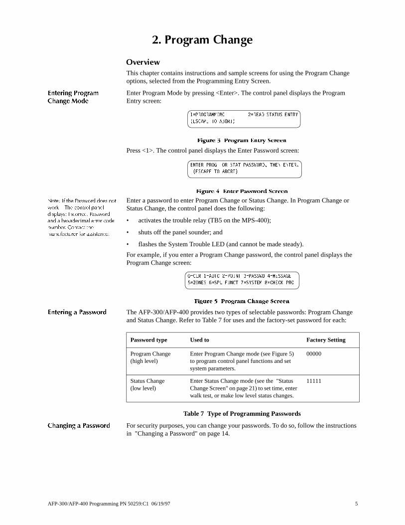
Enter Program Mode by pressing <Enter>. The control panel displays the ProgramEntry screen:
)LJXUH � 3URJUDP (QWU\ 6FUHHQ
Press <1>. The control panel displays the Enter Password screen:
)LJXUH � (QWHU 3DVVZRUG 6FUHHQ
1RWH� ,I WKH 3DVVZRUG GRHV QRWZRUN ² 7KH FRQWURO SDQHOGLVSOD\V� ,QFRUUHFW 3DVVZRUGDQG D KH[DGHFLPDO HUURU FRGHQXPEHU� &RQWDFW WKHPDQXIDFWXUHU IRU DVVLVWDQFH�
Enter a password to enter Program Change or Status Change. In Program ChangStatus Change, the control panel does the following:
• activates the trouble relay (TB5 on the MPS-400);
• shuts off the panel sounder; and
• flashes the System Trouble LED (and cannot be made steady).
For example, if you enter a Program Change password, the control panel displaysProgram Change screen:
)LJXUH � 3URJUDP &KDQJH 6FUHHQ
(QWHULQJ D 3DVVZRUG The AFP-300/AFP-400 provides two types of selectable passwords: Program Chaand Status Change. Refer to Table 7 for uses and the factory-set password for ea
Table 7 Type of Programming Passwords
&KDQJLQJ D 3DVVZRUG For security purposes, you can change your passwords. To do so, follow the instruin "Changing a Password" on page 14.
� 352*5$00,1* � 5($' 67$786 (175<
�(6&$3( 72 $%257�
(17(5 352* 25 67$7 3$66:25'� 7+(1 (17(5�
�(6&$3( 72 $%257�
� &/5 � $872 � 32,17 � 3$66:' � 0(66$*(
� =21(6 � 63/ )81&7 � 6<67(0 � &+(&. 35*
Password type Used to Factory Setting
Program Change(high level)
Enter Program Change mode (see Figure 5) to program control panel functions and set system parameters.
00000
Status Change(low level)
Enter Status Change mode (see the "Status Change Screen" on page 21) to set time, enter walk test, or make low level status changes.
11111
AFP-300/AFP-400 Programming PN 50259:C1 06/19/97 5

�� 3URJUDP &KDQJH Clear Programming Information
. If
reen.
n
uit
re 7:
o not am n. To
lay.
&OHDU�3URJUDPPLQJ�,QIRUPDWLRQ
The Clear option removes all programming information from control panel memoryinstalling the control panel for the first time, use Option 0 to clear control panel memory. To do so, follow these steps:
1. From the Program Change screen, press <0> to display the Clear Program scThe control panel prompts for verification as shown in Figure 6:
)LJXUH � &OHDU 3URJUDP 6FUHHQ
2. Press <Enter> to clear control panel memory or press <Esc> to exit the screewithout clearing.
$XWRSURJUDP
The Autoprogram option provides the following features:
• identifies all installed, addressable devices connected to a Signaling Line Circ(SLC);
• detects new (unprogrammed) devices and new panel modules;
• lets you view, edit, and accept any new devices; and
• loads default program information for new devices. If programming for the first time, the control panel displays a screen similar to Figu
)LJXUH � $XWRSURJUDP 6FUHHQ
SLC devices already programmed into control panel memory do not change and dappear in the Autoprogram Device Count Screen. Devices not matching the progr(not same SLC address and type) display in the Autoprogram Device Count Screeaccept autoprogrammed devices, press <Enter>. The control panel displays the following message:
)LJXUH � $XWRSURJUDP 3URPSW 6FUHHQ
After accepting all devices, the Program Change screen appears in the panel disp
'LVSOD\LQJ D 'HYLFH For each new device, the Autoprogram option selects and displays default programvalues. For example, Figure 9 shows Autoprogram default values for a detector:
)LJXUH � $XWRSURJUDP 'HIDXOW 9DOXHV IRU D 'HWHFWRU
35(66 (17(5 72 &/($5 (17,5( 352*5$0
25 (6&$3( 72 $%257
/���� '(76� �� 02'6 /���� '(76� �� 02'6
3$1(/ 2873876� �� %(//6� ��
6/&� �/RRS �� RQO\ DSSOLHV WRDQ $)3���� FRQWURO SDQHO�
$&&(37 $// '(9,&(6 3/($6( :$,7�
352*50 602.( �3+272� '(7(&725 $''5 ���
=2� = = = = $/�� 3$�� '���
/RRS QXPEHU7\SH &RGH
0XOWL�'HWHFWRU PRGH
&RQWURO�E\�(YHQW �&%(�(TXDWLRQ $ODUP 9HULILFDWLRQ
3UH�$ODUP /HYHO
$ODUP 7KUHVKROG
7ZR�GLJLW DGGUHVV
6 AFP-300/AFP-400 Programming PN 50259:C1 06/19/97
Autoprogram �� 3URJUDP &KDQJH
t
e
in the
—
$XWRSURJUDPPLQJ'HIDXOWV
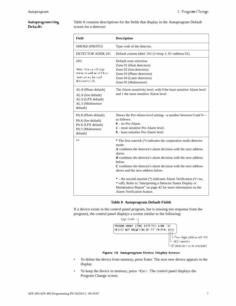
Table 8 contains descriptions for the fields that display in the Autoprogram Defaulscreen for a detector:
Table 8 Autoprogram Default Fields
If a device exists in the control panel program, but is missing (no response from thprogram), the control panel displays a screen similar to the following:
)LJXUH �� $XWRSURJUDP 'HYLFH 'LVSOD\ 6FUHHQ
• To delete the device from memory, press Enter. The next new device appears display.
• To keep the device in memory, press <Esc>. The control panel displays the Program Change screen.
Field Description
SMOKE (PHOTO) Type code of the detector.
DETECTOR ADDR 101 Default custom label: 101 (1=loop 1; 01=address 01).
Z03
1RWH� <RX FDQ FKDQJH]RQHV DV ZHOO DV DGG IRXUPRUH ]RQHV IRU HDFKGHWHFWRU·V &%(�
Default zone selection:Zone 01 (Heat detectors)Zone 02 (Ion detectors)Zone 03 (Photo detectors) Zone 04 (Laser detectors)Zone 05 (Multisensor)
AL:8 (Photo default)
AL:6 (Ion default)AL:6 (LPX default)AL:5 (Multisensor default)
The Alarm sensitivity level, with 9 the least sensitive Alarm leveland 1 the most sensitive Alarm level.
PA:8 (Photo default)
PA:6 (Ion default)PA:6 (LPX default)PA:5 (Multisensor default)
Shows the Pre-Alarm level setting—a number between 0 and 9as follows:0 – no Pre-Alarm.1 – most sensitive Pre-Alarm level.9 – least sensitive Pre-Alarm level.
** * The first asterisk (*) indicates the cooperative multi-detector mode:A combines the detector's alarm decision with the next addressabove.B combines the detector's alarm decision with the next addressbelow.C combines the detector's alarm decision with the next addressabove and the next address below.
* – the second asterisk (*) indicates Alarm Verification (V=on, *=off). Refer to “Interpreting a Detector Status Display or Maintenance Report” on page 42 for more information on the Alarm Verification feature.
352*50 602.( �,21� '(7(&725 $''5 ���
'(9,&( 127 $16:(5,1* '(/(7( )5 0(0� '���
7\SH &RGH
7ZR�GLJLW DGGUHVV �������
' �GHWHFWRU� RU 0 �PRGXOH�
6/& QXPEHU
AFP-300/AFP-400 Programming PN 50259:C1 06/19/97 7

�� 3URJUDP &KDQJH System Defaults
am
6\VWHP�'HIDXOWV
Autoprogram selects the following default system functions the first time you progrthe control panel. System defaults do not appear on the display. Subsequent Autoprogramming will not change previous editing of these functions.
1RWH� )RU GHWDLOV RQ
SURJUDPPLQJ VSHFLDO ]RQHV
)��)� DQG 5��5�� UHIHU WR
�6SHFLDO =RQH &KDQJH� RQ SDJH
��� )RU GHWDLOV RQ SURJUDPPLQJ
V\VWHP SDUDPHWHUV� 5HIHU WR
´6\VWHP )XQFWLRQ
3URJUDPPLQJµ RQ SDJH ���
Table 9 contains a list of the default functions and values:
Table 9 System Defaults
Function Value
Zone 00 Custom label=General Alarm Zone
Zones 01 through 89 Custom label is blank
F0 Label=Presignal/PAS Delay; Delay=180; PAS=N
R0-R9 Label=Release Funct Release Control
ABORT=ULI; CROSS=N; SOAK=0000; Delay=00
N/A
F5 and F6 Label=Time Function Time ControlOff=00:00; Days=SMTWTFSH
F7 Label=Holiday Funct; all days are 00/00
F8 Label=Code Type=March Time
F9 Label=Pre-Alarm FunctDefault=Alert
System Parameters (see Figure 28 on page 18)
SIL INH=000 AUTO=000 VERIFY=30USA TIMETERM_SUPERV=NOLocTBLINK=Y ST=4 ACS=N
Passwords Program Change=00000, Status Change=11111
All Systems Normal N/A
Custom Message 40 blanks
8 AFP-300/AFP-400 Programming PN 50259:C1 06/19/97
Point Programming �� 3URJUDP &KDQJH
elete2> to
the
tor,
reen,
3RLQW�3URJUDPPLQJ
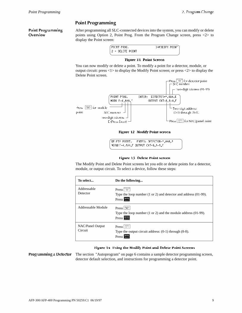
3RLQW 3URJUDPPLQJ2YHUYLHZ
After programming all SLC-connected devices into the system, you can modify or dpoints using Option 2, Point Prog. From the Program Change screen, press <display the Point screen:
)LJXUH �� 3RLQW 6FUHHQ
You can now modify or delete a point. To modify a point for a detector, module, oroutput circuit: press <1> to display the Modify Point screen; or press <2> to displayDelete Point screen.
)LJXUH �� 0RGLI\ 3RLQW VFUHHQ
)LJXUH �� 'HOHWH 3RLQW VFUHHQ
The Modify Point and Delete Point screens let you edit or delete points for a detecmodule, or output circuit. To select a device, follow these steps:
)LJXUH �� 8VLQJ WKH 0RGLI\ 3RLQW DQG 'HOHWH 3RLQW 6FUHHQV
3URJUDPPLQJ D 'HWHFWRU The section "Autoprogram" on page 6 contains a sample detector programming scdetector default selection, and instructions for programming a detector point.
To select... Do the following...
AddressableDetector
Press +Type the loop number (1 or 2) and detector and address (01-99).
Press 5
Addressable Module Press ,Type the loop number (1 or 2) and the module address (01-99).
Press 5
NAC/Panel Output Circuit
Press -Type the output circuit address: (0-1) through (8-8).
Press 5
32,17 352*� � 02',)< 32,17
� '(/(7( 32,17
32,17 352*� (17(5� '(7(&725 �$$$�(
02'8/( ��$$$�( 287387 &.7 �$�$�(
6/& QXPEHU
3UHVV�, IRU PRGXOH
SRLQW
7ZR�GLJLW DGGUHVV �������
6/& QXPEHU
7ZR�GLJLW DGGUHVV
3UHVV+ IRU GHWHFWRU SRLQW
( �3UHVV (QWHU� 3UHVV- IRU 1$&�SDQHO SRLQW
7ZR�GLJLW DGGUHVV������ WKURXJK ������
'(/(7( 32,17� (17(5� '(7(&725 �$$$�(
02'8/( ��$$$�( 287387 &.7 �$�$�(
AFP-300/AFP-400 Programming PN 50259:C1 06/19/97 9

�� 3URJUDP &KDQJH Point Programming
tion
s lists
s
for
ing
3URJUDPPLQJ D 0RQLWRU0RGXOH �00;�
When you select a device, the control panel returns a screen that displays informaabout the point. For example, Figure 15 shows information for a sample monitor module (M101) on the panel display:
1RWH� 6/&� �/RRS �� RQO\
DSSOLHV WR DQ $)3�����
)LJXUH �� 00; 3RLQW 6FUHHQ
The Type Code selection blinks, indicating that you can press the Next or PreviouSelection keys to scroll through the Type Code selections. Refer to Table 11, whichthe function for all Monitor Module Type Codes. You can also do the following:
1. Use the arrow and alphanumeric keys to modify point information, such as theCBE equation.
2. When finished modifying a point, press <Enter>; then use the Next or Previoukeys to select another point.
00; 'HIDXOW =RQH$VVLJQPHQWV
Table 10 lists the monitor module address range and the default zone assignmenteach range:
Table 10 Monitor Module (MMX) Default Zones
Change default zones for a monitor module as shown in Table 11, “AutoprogrammDefault Fields.”
352*50 021,,25 02'8/( $''5 ���
=�� = = = = 0���
7ZR�GLJLW DGGUHVV �������
6/& QXPEHU
' �GHWHFWRU� RU 0 �PRGXOH�
%OLQNLQJ 7\SH &RGH VHOHFWLRQ
Monitor Module Address Zone Default
01 through 19 Z04
20 through 39 Z05
40 through 59 Z06
60 through 79 Z07
80 through 99 Z08
1RWH� 7KH 7\SH &RGH LV XVHG WR
FKDQJH WKH IXQFWLRQ RI D SRLQW�
10 AFP-300/AFP-400 Programming PN 50259:C1 06/19/97

Point Programming �� 3URJUDP &KDQJH
7\SH &RGHV IRU 0RQLWRU0RGXOHV �00;�
Table 11 lists Monitor Module (MMX) Type Codes:
Table 11 Monitor Module (MMX) Type Codes
Type Code Label Special Function
Monitor none (default)
Pull Station none
Smoke Detect none
Heat Detect Use to monitor conventional detectors
Blank (12 spaces) none (use when no other Type Code applies)
Waterflow causes a non-silenceable alarm
Supervisory becomes a supervisory point
Tamper becomes a supervisory point
Non Fire special non-alarm point
Hazard Alert special non-alarm point
Fire Control special non-alarm point
Abort Switch aborts the release zone
Man. Release overrides Abort
Silence functions like the Silence switch
System Reset functions like the Reset switch
Evacuate functions like the Alarm Activate switch
PAS Inhibit overrides Presignal
Trouble Mon short = trouble
Burglar Ala causes a Security alarm on an open or short
Tele. Page allows remote paging to a fire area
AllCall Page allows All Call paging from a remote phone in the installation
Man Rel Delay initiate manual release with 10-second delay
Second Shot reactivate release output, second agent discharge
Sprinklr Sys allows waterflow and supervisory monitoring on same module
Comb. Monitor allows waterflow and supervisory monitoring on same module
AFP-300/AFP-400 Programming PN 50259:C1 06/19/97 11
�� 3URJUDP &KDQJH Point Programming
is ing a
s ).
us
d
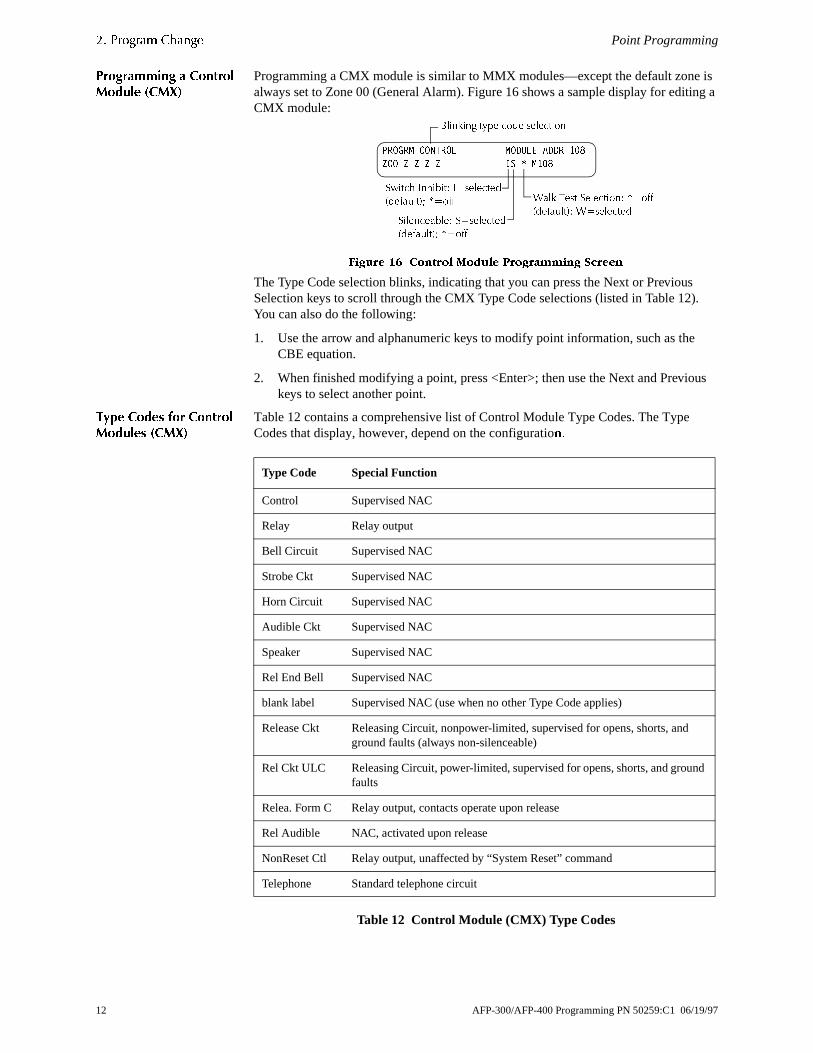
3URJUDPPLQJ D &RQWURO0RGXOH �&0;�
Programming a CMX module is similar to MMX modules—except the default zonealways set to Zone 00 (General Alarm). Figure 16 shows a sample display for editCMX module:
)LJXUH �� &RQWURO 0RGXOH 3URJUDPPLQJ 6FUHHQ
The Type Code selection blinks, indicating that you can press the Next or PreviouSelection keys to scroll through the CMX Type Code selections (listed in Table 12You can also do the following:
1. Use the arrow and alphanumeric keys to modify point information, such as theCBE equation.
2. When finished modifying a point, press <Enter>; then use the Next and Previokeys to select another point.
7\SH &RGHV IRU &RQWURO0RGXOHV �&0;�
Table 12 contains a comprehensive list of Control Module Type Codes. The TypeCodes that display, however, depend on the configuratioQ�
Table 12 Control Module (CMX) Type Codes
:DON 7HVW 6HOHFWLRQ� RII�GHIDXOW�� : VHOHFWHG
6ZLWFK ,QKLELW� , VHOHFWHG�GHIDXOW�� RII
%OLQNLQJ W\SH FRGH VHOHFWLRQ
6LOHQFHDEOH� 6 VHOHFWHG�GHIDXOW�� RII
352*50 &21752/ 02'8/( $''5 ���
=2� = = = = ,6 0���
Type Code Special Function
Control Supervised NAC
Relay Relay output
Bell Circuit Supervised NAC
Strobe Ckt Supervised NAC
Horn Circuit Supervised NAC
Audible Ckt Supervised NAC
Speaker Supervised NAC
Rel End Bell Supervised NAC
blank label Supervised NAC (use when no other Type Code applies)
Release Ckt Releasing Circuit, nonpower-limited, supervised for opens, shorts, andground faults (always non-silenceable)
Rel Ckt ULC Releasing Circuit, power-limited, supervised for opens, shorts, and grounfaults
Relea. Form C Relay output, contacts operate upon release
Rel Audible NAC, activated upon release
NonReset Ctl Relay output, unaffected by “System Reset” command
Telephone Standard telephone circuit
12 AFP-300/AFP-400 Programming PN 50259:C1 06/19/97
Point Programming �� 3URJUDP &KDQJH
gh e
s to
pe
)
s,
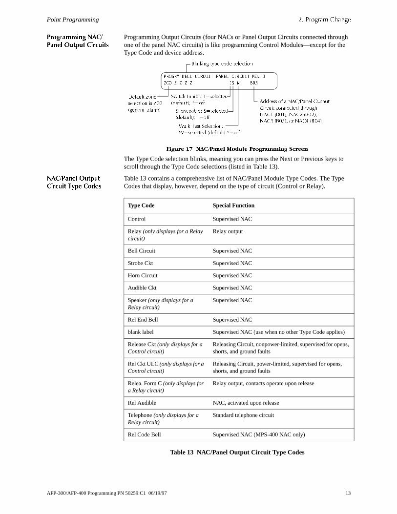
3URJUDPPLQJ 1$&�3DQHO 2XWSXW &LUFXLWV
Programming Output Circuits (four NACs or Panel Output Circuits connected throuone of the panel NAC circuits) is like programming Control Modules—except for thType Code and device address.
)LJXUH �� 1$&�3DQHO 0RGXOH 3URJUDPPLQJ 6FUHHQ
The Type Code selection blinks, meaning you can press the Next or Previous keyscroll through the Type Code selections (listed in Table 13).
1$&�3DQHO 2XWSXW&LUFXLW 7\SH &RGHV
Table 13 contains a comprehensive list of NAC/Panel Module Type Codes. The TyCodes that display, however, depend on the type of circuit (Control or Relay).
Table 13 NAC/Panel Output Circuit Type Codes
352*50 %(// &,5&8,7 3$1(/ &,5&8,7 12� �
=�� = = = = ,6 : %��
:DON 7HVW 6HOHFWLRQ�
: VHOHFWHG �GHIDXOW� RII
6ZLWFK ,QKLELW� , VHOHFWHG
�GHIDXOW�� RII
%OLQNLQJ W\SH FRGH VHOHFWLRQ
6LOHQFHDEOH� 6 VHOHFWHG
�GHIDXOW�� RII
$GGUHVV RI D 1$&�3DQHO 2XWSXW
&LUFXLW FRQQHFWHG WKURXJK
1$&� �%���� 1$&� �%����
1$&� �%���� RU 1$&� �%���
'HIDXOW ]RQH
VHOHFWLRQ LV =��
�JHQHUDO DODUP�
Type Code Special Function
Control Supervised NAC
Relay (only displays for a Relay circuit)
Relay output
Bell Circuit Supervised NAC
Strobe Ckt Supervised NAC
Horn Circuit Supervised NAC
Audible Ckt Supervised NAC
Speaker (only displays for a Relay circuit)
Supervised NAC
Rel End Bell Supervised NAC
blank label Supervised NAC (use when no other Type Code applies
Release Ckt (only displays for a Control circuit)
Releasing Circuit, nonpower-limited, supervised for openshorts, and ground faults
Rel Ckt ULC (only displays for a Control circuit)
Releasing Circuit, power-limited, supervised for opens, shorts, and ground faults
Relea. Form C (only displays for a Relay circuit)
Relay output, contacts operate upon release
Rel Audible NAC, activated upon release
Telephone (only displays for a Relay circuit)
Standard telephone circuit
Rel Code Bell Supervised NAC (MPS-400 NAC only)
AFP-300/AFP-400 Programming PN 50259:C1 06/19/97 13

�� 3URJUDP &KDQJH Changing a Password
e ons in
ge. een:
d line
een:
er.
&KDQJLQJ�D�3DVVZRUG
Password Change lets you customize a high-level or low-level password. From thProgram Change screen, press <3> to display the screen, then follow the instructiTable 14.
)LJXUH �� &KDQJH 3DVVZRUG 6FUHHQ
To change a password, follow the instructions in Table 14:
Table 14 Changing a Password
&KDQJLQJ�WKH�6\VWHP�0HVVDJH�
The Message option lets you change the 40-character All Systems Normal messaFrom the Program Change screen, press <4> to display the Message Change scr
)LJXUH �� 0HVVDJH &KDQJH VFUHHQ
To change the system message, follow these guidelines:
• Change one character at a time, indicated by the blinking cursor on the seconof the display.
• Enter up to 40 characters maximum.Table 15 contains instructions for entering characters in the Message Change scr
Table 15 Changing System Message
To... Press... Then...
Change the Program password.+ type the new Program password.
Change the Status password. , type the new Status password.
Save the password. & the Password Change screen appears.
Leave the edit screen without changing a password.
<Backspace> or <Esc>
the Password Change screen appears.
To... Do this...
Change a blinking character
Type a character from the keypad.
Move to the next character Press *
Enter additional characters (!@#$%^=*:;)
Press then press a number key as follows:
� # � � � A � �
� � � � � � � � � �
For example, press then press <7> to enter a “=” charact
Save the new message Press &
&+$1*( 3$66:25' �11111�( 352*5$0
��11111� ( 67$786
'LVSOD\ DUHD IRU QHZ SDVVZRUG
6<6 1250$/ 0(66$*(
0HVVDJH FKDQJH DUHD%OLQNLQJ FXUVRU SURPSW
/2:(5
&$6(
/2:(5
&$6(
14 AFP-300/AFP-400 Programming PN 50259:C1 06/19/97
Changing a Custom Label �� 3URJUDP &KDQJH
the
n the
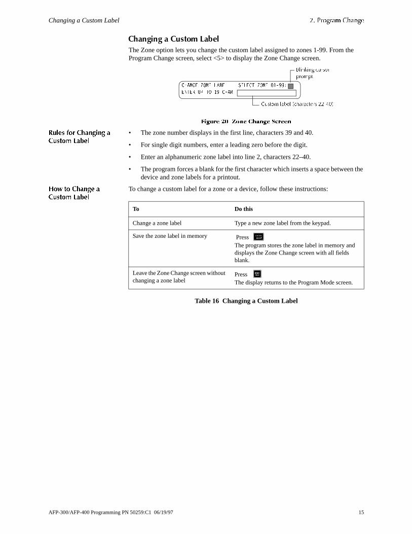
&KDQJLQJ�D�&XVWRP�/DEHO
The Zone option lets you change the custom label assigned to zones 1-99. From Program Change screen, select <5> to display the Zone Change screen.
)LJXUH �� =RQH &KDQJH 6FUHHQ
5XOHV IRU &KDQJLQJ D&XVWRP /DEHO
• The zone number displays in the first line, characters 39 and 40.
• For single digit numbers, enter a leading zero before the digit.
• Enter an alphanumeric zone label into line 2, characters 22–40.
• The program forces a blank for the first character which inserts a space betweedevice and zone labels for a printout.
+RZ WR &KDQJH D&XVWRP /DEHO
To change a custom label for a zone or a device, follow these instructions:
Table 16 Changing a Custom Label
&+$1*( =21( /$%(/ 6(/(&7 =21( ������
(17(5 83 72 �� &+$5
&XVWRP ODEHO �FKDUDFWHUV ������
%OLQNLQJ FXUVRUSURPSW
To Do this
Change a zone label Type a new zone label from the keypad.
Save the zone label in memory Press &The program stores the zone label in memory and displays the Zone Change screen with all fields blank.
Leave the Zone Change screen without changing a zone label
Press 6The display returns to the Program Mode screen.
AFP-300/AFP-400 Programming PN 50259:C1 06/19/97 15

�� 3URJUDP &KDQJH Special Zone Change
0-F9 y the
l
mple, ns
reen.
er
on
6SHFLDO�=RQH�&KDQJH�
The Special Zone Change option lets you change the program for special zones For releasing zones R0-R9. From the Program Change screen, select <6> to displaSpecial Function Change screen.
)LJXUH �� 6SHFLDO )XQFWLRQ &KDQJH 6FUHHQ
Table 17 contains descriptions for each special function that appears in the SpeciaFunction Change screen.
Table 17 Special Functions
6SHFLDO�)XQFWLRQ�6FUHHQV
Select Function screens by entering the special function letter and number (for exaF0, R0, and so on) from the Special Function Change screen. The following sectioshow sample screens that display when you select a special function.
)� �3UHVLJQDO� The Presignal screen provides fields for changing the delay time or PAS. From theSpecial Function Change screen, select <F0> to display the Presignal Function sc
)LJXUH �� 3UHVLJQDO 6FUHHQ
Special Function Specifies...
F0 (Presignal) the delay time or the PAS selection.
F1 (Trouble less AC) an output programmed to turn on/off if a system trouble—oththan an AC power loss—occurs.
F2 (AC Trouble) an output programmed to turn on/off if an AC power loss or a brownout condition occurs.
F3 (Security) an output programmed to turn on/off if a Security input activates.
F4 (Supervisory) an output programmed to turn on/off if a Supervisory input activates.
F5-F6 (Time Control) the start time, stop time, or days of the week.
F7 (Holiday) up to nine holiday dates. An F7-programmed device activates the specified holiday dates.
F8 (Coding) one of four code types: March Time, Temporal, California, or Two Stage. F8 only takes effect if you program one or more NACs to F8.
F9 (Pre-Alarm) the Alert and Action Pre-Alarm level.
R0-R9 (Releasing) the delay times, abort type, cross zoning, or soak time.
63(&,$/ )81&7,21� )� 35(6,* 5��5� 5(/
)��)� 7,0( )� +2/ )� &2'( )� 35(�$/$50
35* 35(6,*1$/ )81&7 35(6,*1$/ '(/$<
'(/$< ��� 3$6 12 )��
16 AFP-300/AFP-400 Programming PN 50259:C1 06/19/97
Special Function Screens �� 3URJUDP &KDQJH
. e
ays the
e
h en,
rm Alarm
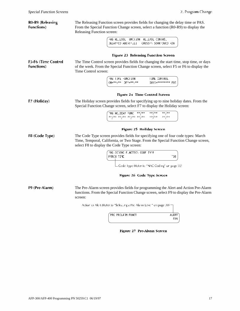
5��5� �5HOHDVLQJ
)XQFWLRQV�
The Releasing Function screen provides fields for changing the delay time or PASFrom the Special Function Change screen, select a function (R0-R9) to display thReleasing Function screen:
)LJXUH �� 5HOHDVLQJ )XQFWLRQ 6FUHHQ
)��)� �7LPH &RQWURO
)XQFWLRQV�
The Time Control screen provides fields for changing the start time, stop time, or dof the week. From the Special Function Change screen, select F5 or F6 to displayTime Control screen:
)LJXUH �� 7LPH &RQWURO 6FUHHQ
)� �+ROLGD\� The Holiday screen provides fields for specifying up to nine holiday dates. From thSpecial Function Change screen, select F7 to display the Holiday screen:
)LJXUH �� +ROLGD\ 6FUHHQ
)� �&RGH 7\SH� The Code Type screen provides fields for specifying one of four code types: MarcTime, Temporal, California, or Two Stage. From the Special Function Change screselect F8 to display the Code Type screen:
)LJXUH �� &RGH 7\SH 6FUHHQ
)� �3UH�$ODUP� The Pre-Alarm screen provides fields for programming the Alert and Action Pre-Alafunctions. From the Special Function Change screen, select F9 to display the Pre-screen:
)LJXUH �� 3UH�$ODUP 6FUHHQ
35* 5(/($6( )81&7,21 5(/($6( &21752/
'(/$< �� $%257 8/, &5266 1 62$. ���� 5��
35* 7,0( )81&7,21 7,0( &21752/
21 � 2)) � '$<6 )��
35* +2/,'$< )81& � � �
� � � � � �
35* &2',1* )81&7,21 &2'( 7<3(
0$5&+ 7,0( )��
&RGH 7\SH �5HIHU WR ´1$& &RGLQJµ RQ SDJH ���
35* 35(/$50 )81&7 $/(57
)��
$FWLRQ RU $OHUW �5HIHU WR ´6HOHFWLQJ D 3UH�$ODUP /HYHOµ RQ SDJH ���
AFP-300/AFP-400 Programming PN 50259:C1 06/19/97 17

�� 3URJUDP &KDQJH System Function Programming
ge
6\VWHP�)XQFWLRQ�3URJUDPPLQJ
6\VWHP )XQFWLRQV The System option lets you set general system functions. From the Program Chanscreen, select <7> to display the System Function screen:
)LJXUH �� 6\VWHP )XQFWLRQ 6FUHHQ
Table 18 contains settings for general system functions.
Table 18 Setting General System Functions
System Function Setting Default
SIL INH (Silence Inhibit time) 0 to 300 seconds 0
AUTO (Auto Silence time) • 000 (none)• 600 to 900 seconds
0
VERIFY (Alarm Verification time) 0 to 30 seconds 30
USA TIME EUR time with Next/Previous keys European time format changes to 24-hour time, and places the day before the month
USA time
TERM_SUPERV No or Yes No
Terminal mode – one of three operating modes of PC or terminal connected to the control panel through TB2 on the CPU. For a complete list of functions, refer to the Installation Manual.
• LocT (terminal connected to control panel and located in same room);
• LocM (same as LocT but requires password); or
• RemT (terminal connected through a modem for Read Status only).
LocT
BLINK=Y (device LED blink) Set to Blink=N (no blink) by pressing the Up/Down keys.
Blink=Y
ST=4 – the NFPA wiring style used for the SLC loop.
ST=6 (Style 6 SLC loop wiring)ST=4 (Style 4 SLC loop wiring)
ST=4
ACS – Use ACS Selection Groups (Refer to “Annunciator Options” on page 19).
N or Y ACS=N
6,/ ,1+ ��� $872 ��� 9(5,)< �� 86$ 7,0(
7(50B683(59 12 /RF7 %/,1. < 67 � $&6 1
18 AFP-300/AFP-400 Programming PN 50259:C1 06/19/97

System Function Programming �� 3URJUDP &KDQJH
S lays
r to
0) to
s of t of
$QQXQFLDWRU 2SWLRQV Use Annunciator Selection screens to select information that will display on the ACannunciators. (Table 19 contains the ACS display selections.) Setting ACS=Y dispthe Annunciator Selection 1 Screen, address A1–A10. If UDACT=Y, you can use addresses A11-A19 with UDACTs having software release #UDACT01.0 or highesend control panel status to a UDACT.
)LJXUH �� $QQXQFLDWRU 6HOHFWLRQ � 6FUHHQ
If UDACT=N:
• The control panel displays the Annunciator Selection 2 Screen (Figure 30), addresses A11-A19.
• You can use addresses A11–A19 on Annunciator Selection 2 Screen (Figure 3select annunciators.
)LJXUH �� $QQXQFLDWRU 6HOHFWLRQ � 6FUHHQ
The control panel’s annunciation points are divided into nine ACS selection group64 points, listed in Table 19. Refer to Appendix A in the Installation Manual for a listhe 64 points within the ACS Selection Groups.
Table 19 ACS Selection Groups
ACS Selection Group Annunciator Display
1 CPU Status and Zones 1-56
2 Zones 57-99, NAC Ckts 1-4 and 16 Special Zones
3 Intelligent Modules 101 to 164
4 Intelligent Modules 201-264 (AFP-400 only)
5 Intelligent Modules 165-196 and 265-296 (AFP-400 only)
6 Detectors 101 to 164 on SLC loop 1
7 Detectors 201-264 on SLC loop 2 (AFP-400 only)
8 Detectors 165-196 and 265-296 (AFP-400 only)
9 NAC/Panel Output Circuit Modules (64 points)
* or 0 Annunciator Not Installed At Address
$1181 6(/(&7,21� $� $� $� $�
$� $� $� $� $� $�� 8'$&7 1
$&6 6HOHFWLRQ *URXS ����� RU QRW VHOHFWHG
$ $&6 $GGUHVV
$1$1181 6(/(&7,21� $�� $�� $��
$�� $�� $�� $�� $�� $��
$&6 6HOHFWLRQ *URXS ������� RU QRW VHOHFWHG
$ $&6 $GGUHVV
AFP-300/AFP-400 Programming PN 50259:C1 06/19/97 19

�� 3URJUDP &KDQJH Check
not
tion
tion
cuit
for
m;
or Point
$&6 6HOHFWLRQ *URXS
([DPSOH
Figure 31 shows an example of a screen listing ACS Selection Groups:
)LJXUH �� $QQXQFLDWRU 6HOHFWLRQ 6FUHHQ ([DPSOH
Figure 31 shows annunciator selections for addresses A1-A3 (addresses A4-A10 selected) and addresses A11–A19 set to send panel status to a UDACT.
• Annunciators set to Address 1 display the status of detectors 1-64 (ACS SelecGroup 6) on SLC loop 1;
• Annunciators set to Address 2 display the status of detectors 1-64 (ACS SelecGroup 7) on SLC loop 2 (SLC2 used only on AFP-400); and
• Annunciators set to Address 3 display the status of the NAC/Panel Output Cirmodules (ACS Selection Group 9).
&KHFN
When finished programming, use the Check option to search the program entries possible errors. From the Program Change screen, select <8>. The Check optionsearches the program for the following conditions:
• Output points mapped to a zone without a mapped input.
• A zone with mapped input points without mapped output points (including Z00outputs).
• Releasing zone inputs (R0-R9) with no RELEASE CKT outputs mapped to theor RELEASE CKT outputs with no R0-R9 inputs mapped to them.
• RO-R9 inputs not mapped to MAN RELEASE.
If the Check option detects multiple devices that fail the check, press the PreviousNext key to step through the devices. If the Check option displays errors, return to Programming ( "Point Programming" on page 9) and correct the errors. Figure 32 shows a sample display of program screen WKDW DSSHDUV DIWHU D VXFFHVVIXO SURJUDP
FKHFN�
)LJXUH �� 'LVSOD\ $IWHU 6XFFHVVIXO 3URJUDP &KHFN
$1181 6(/(&7,21� $� � $� � $� � $�
$� $� $� $� $� $�� 8'$&7 <
$&6 6HOHFWLRQ *URXS �
$ $&6 $GGUHVV
3URJUDP &KHFN 2.�
5(�7(67 3$1(/ 12: �����$ )UL ��������
20 AFP-300/AFP-400 Programming PN 50259:C1 06/19/97
ot
so on.
ules,
en:
or
���6WDWXV�&KDQJH
2YHUYLHZ1RWH� $VVLJQ WKH 6WDWXV &KDQJH
SDVVZRUG WR SHUVRQV ZKR GR
QRW QHHG WR GR DSSOLFDWLRQ
SURJUDPPLQJ RU
DXWRSURJUDPPLQJ�
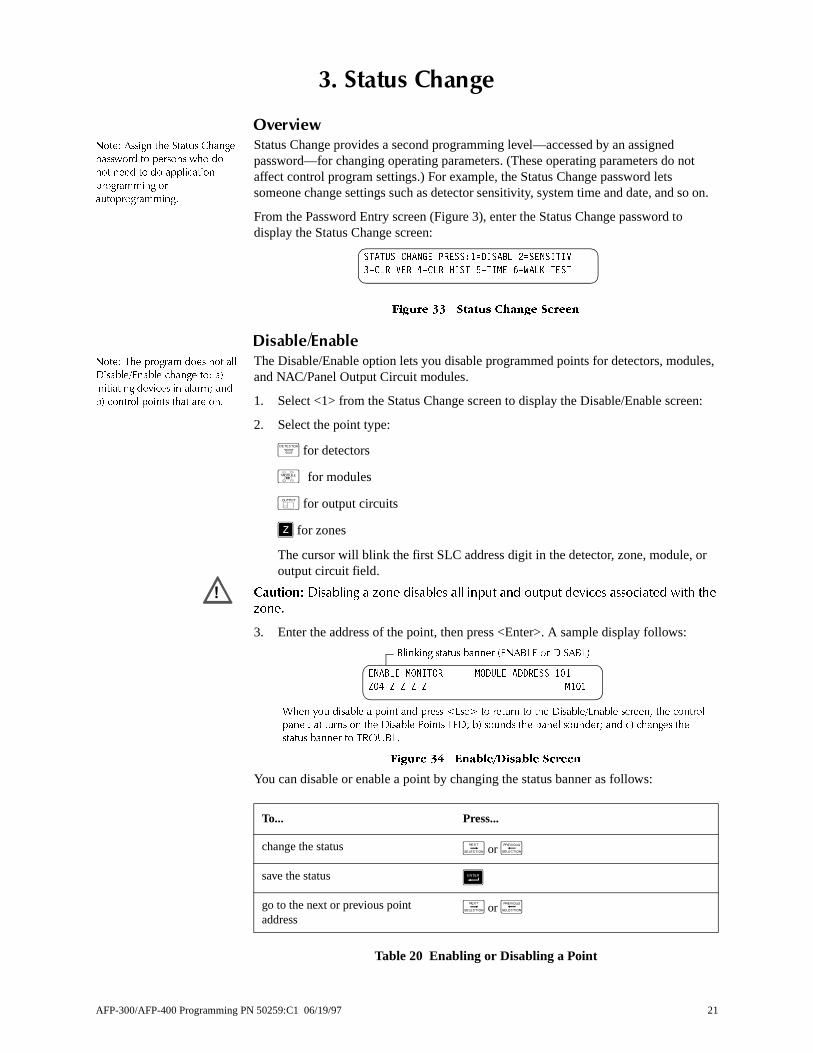
Status Change provides a second programming level—accessed by an assigned password—for changing operating parameters. (These operating parameters do naffect control program settings.) For example, the Status Change password lets someone change settings such as detector sensitivity, system time and date, and
From the Password Entry screen (Figure 3), enter the Status Change password todisplay the Status Change screen:
)LJXUH �� 6WDWXV &KDQJH 6FUHHQ
'LVDEOH�(QDEOH1RWH� 7KH SURJUDP GRHV QRW DOO
'LVDEOH�(QDEOH FKDQJH WR� D�
LQLWLDWLQJ GHYLFHV LQ DODUP� DQG
E� FRQWURO SRLQWV WKDW DUH RQ�
The Disable/Enable option lets you disable programmed points for detectors, modand NAC/Panel Output Circuit modules.
1. Select <1> from the Status Change screen to display the Disable/Enable scre
2. Select the point type:
+ for detectors
,�for modules
- for output circuits
] for zones
The cursor will blink the first SLC address digit in the detector, zone, module, output circuit field.
&DXWLRQ� 'LVDEOLQJ D ]RQH GLVDEOHV DOO LQSXW DQG RXWSXW GHYLFHV DVVRFLDWHG ZLWK WKH
]RQH�
3. Enter the address of the point, then press <Enter>. A sample display follows:
)LJXUH �� (QDEOH�'LVDEOH 6FUHHQ
You can disable or enable a point by changing the status banner as follows:
Table 20 Enabling or Disabling a Point
67$786 &+$1*( 35(66�� ',6$%/ � 6(16,7,9
� &/5 9(5 � &/5 +,67 � 7,0( � :$/. 7(67
To... Press...
change the status / or 0
save the status &
go to the next or previous point address
/ or 0
�
:KHQ \RX GLVDEOH D SRLQW DQG SUHVV �(VF! WR UHWXUQ WR WKH 'LVDEOH�(QDEOH VFUHHQ� WKH FRQWURO
SDQHO� D� WXUQV RQ WKH 'LVDEOH 3RLQWV /('� E� VRXQGV WKH SDQHO VRXQGHU� DQG F� FKDQJHV WKH
VWDWXV EDQQHU WR 7528%/�
%OLQNLQJ VWDWXV EDQQHU �(1$%/( RU ',6$%/�
(1$%/( 021,725 02'8/( $''5(66 ���
=�� = = = = 0���
AFP-300/AFP-400 Programming PN 50259:C1 06/19/97 21
�� 6WDWXV &KDQJH Detector Sensitivity
ity) y the
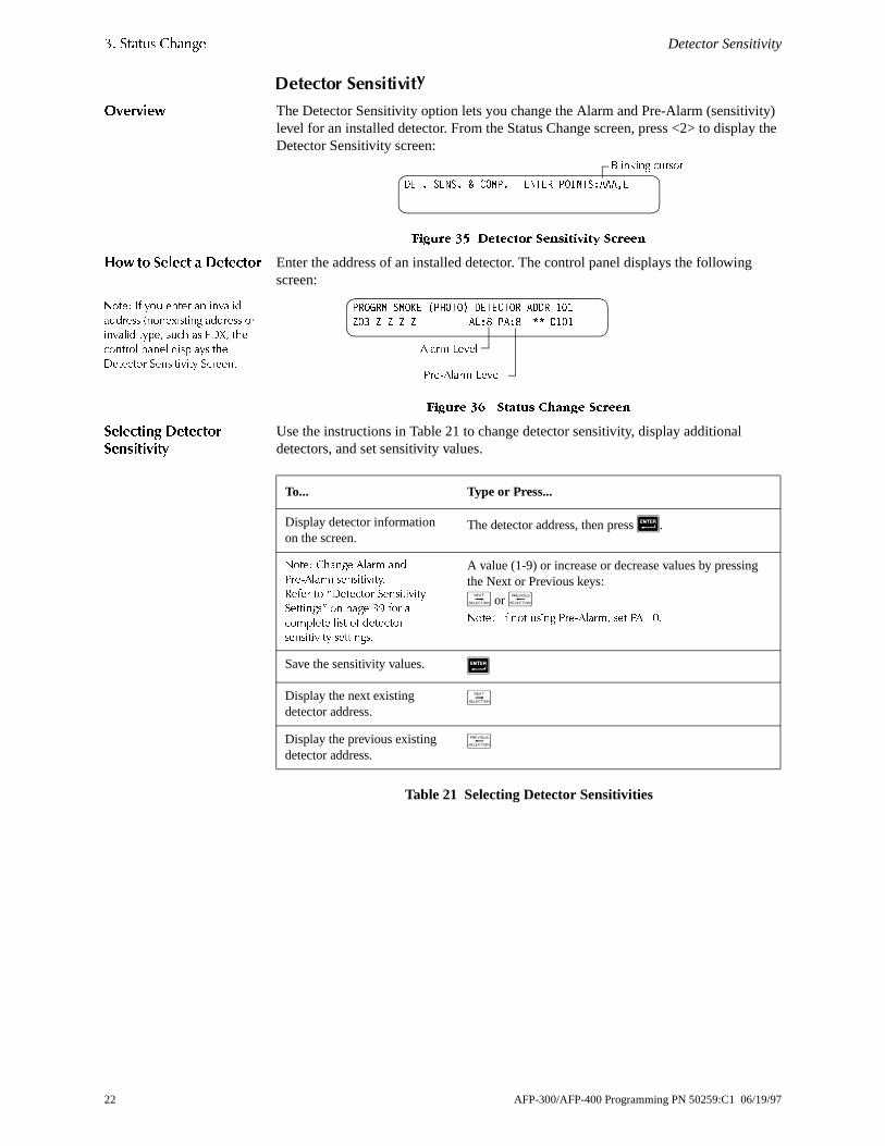
'HWHFWRU�6HQVLWLYLW\
2YHUYLHZ The Detector Sensitivity option lets you change the Alarm and Pre-Alarm (sensitivlevel for an installed detector. From the Status Change screen, press <2> to displaDetector Sensitivity screen:
)LJXUH �� 'HWHFWRU 6HQVLWLYLW\ 6FUHHQ
+RZ WR 6HOHFW D 'HWHFWRU Enter the address of an installed detector. The control panel displays the followingscreen:
)LJXUH �� 6WDWXV &KDQJH 6FUHHQ
6HOHFWLQJ 'HWHFWRU6HQVLWLYLW\
Use the instructions in Table 21 to change detector sensitivity, display additional detectors, and set sensitivity values.
Table 21 Selecting Detector Sensitivities
'(7� 6(16� &203� (17(5 32,176�$$$�(
%OLQNLQJ FXUVRU
352*50 602.( �3+272� '(7(&725 $''5 ���
=2� = = = = $/�� 3$�� '���
$ODUP /HYHO
3UH�$ODUP /HYHO
To... Type or Press...
Display detector information on the screen.
The detector address, then press 5.
1RWH� &KDQJH $ODUP DQG
3UH�$ODUP VHQVLWLYLW\�
5HIHU WR ´'HWHFWRU 6HQVLWLYLW\
6HWWLQJVµ RQ SDJH �� IRU D
FRPSOHWH OLVW RI GHWHFWRU
VHQVLWLYLW\ VHWWLQJV�
A value (1-9) or increase or decrease values by pressing the Next or Previous keys:
/ or 01RWH� ,I QRW XVLQJ 3UH�$ODUP� VHW 3$ ��
Save the sensitivity values. 5
Display the next existing detector address.
/
Display the previous existing detector address.
0
1RWH� ,I \RX HQWHU DQ LQYDOLG
DGGUHVV �QRQH[LVWLQJ DGGUHVV RU
LQYDOLG W\SH� VXFK DV )';� WKH
FRQWURO SDQHO GLVSOD\V WKH
'HWHFWRU 6HQVLWLYLW\ 6FUHHQ�
22 AFP-300/AFP-400 Programming PN 50259:C1 06/19/97

Clear Verification Counters �� 6WDWXV &KDQJH
ors t <3>
e
<4>
5>
m
ad.
&OHDU�9HULILFDWLRQ�&RXQWHUV
The Clear Verification screen lets you clear all verification tally counters for detectselected for Alarm Verification. From the Status Change screen (Figure 33), selecto display the Clear Verification screen:
)LJXUH �� &OHDU 9HULILFDWLRQ 6FUHHQ
From the &OHDU 9HULILFDWLRQ screen, you can do the following:
• Press <Enter> to clear all verification counters and return to the Status Changscreen; or
• Press <Esc> to return to the Status Change screen without clearing.
&OHDU�WKH�+LVWRU\�)LOH
The Clear History screen lets you clear the entire history file from memory. Selectfrom the Status Change screen (Figure 33) to display the Clear History screen:
)LJXUH �� &OHDU +LVWRU\ 6FUHHQ
From the Clear History screen, you can do the following:
• Press <Enter> to clear the contents of the history file and return to the Status Change screen; or
• Press <Esc> to return to the Status Change screen without clearing.
6HW�WKH�6\VWHP�7LPH�DQG�'DWH
The Time/Date option lets you set the time and date for the system clock. Select <from the Status Change screen (Figure 33) to display the Time/Date screen:
)LJXUH �� 6\VWHP 7LPH�'DWH 6FUHHQ
The first digit flashes until you change the value or press <Enter>. To set the systetime and date, follow the instructions in Table 22.
Table 22 Changing the System Time and Date
To... Do this...
Change the time and date values Input values from the numeric keys on the keyp
Change A (AM) or P (PM) Press / or 0
Change the day Press / or 0
Move to another digit Press *
Save the time and date and return Press 5
35(66 (17(5 72 &/($5 9(5,),&$7,21 &28176
25 (6&$3( 72 $%257
35(66 (17(5 72 &/($5 +,6725< ),/(
25 (6&$3( 72 $%257
&+$1*( 7,0(�'$7(
�����$ 78( ��������
AFP-300/AFP-400 Programming PN 50259:C1 06/19/97 23
�� 6WDWXV &KDQJH Walk Test
:
tify in
the plete
mber
r Txx”
hen
r
:DON�7HVW
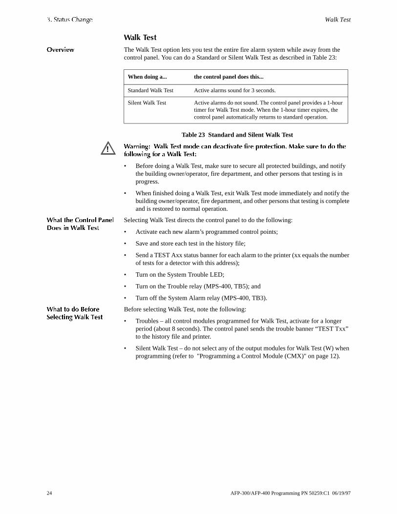
2YHUYLHZ The Walk Test option lets you test the entire fire alarm system while away from thecontrol panel. You can do a Standard or Silent Walk Test as described in Table 23
Table 23 Standard and Silent Walk Test
:DUQLQJ� :DON 7HVW PRGH FDQ GHDFWLYDWH ILUH SURWHFWLRQ� 0DNH VXUH WR GR WKHIROORZLQJ IRU D :DON 7HVW�
• Before doing a Walk Test, make sure to secure all protected buildings, and nothe building owner/operator, fire department, and other persons that testing isprogress.
• When finished doing a Walk Test, exit Walk Test mode immediately and notify building owner/operator, fire department, and other persons that testing is comand is restored to normal operation.
:KDW WKH &RQWURO 3DQHO'RHV LQ :DON 7HVW
Selecting Walk Test directs the control panel to do the following:
• Activate each new alarm’s programmed control points;
• Save and store each test in the history file;
• Send a TEST Axx status banner for each alarm to the printer (xx equals the nuof tests for a detector with this address);
• Turn on the System Trouble LED;
• Turn on the Trouble relay (MPS-400, TB5); and
• Turn off the System Alarm relay (MPS-400, TB3).
:KDW WR GR %HIRUH6HOHFWLQJ :DON 7HVW
Before selecting Walk Test, note the following:
• Troubles – all control modules programmed for Walk Test, activate for a longeperiod (about 8 seconds). The control panel sends the trouble banner “TEST to the history file and printer.
• Silent Walk Test – do not select any of the output modules for Walk Test (W) wprogramming (refer to "Programming a Control Module (CMX)" on page 12).
When doing a... the control panel does this...
Standard Walk Test Active alarms sound for 3 seconds.
Silent Walk Test Active alarms do not sound. The control panel provides a 1-houtimer for Walk Test mode. When the 1-hour timer expires, the control panel automatically returns to standard operation.
�
24 AFP-300/AFP-400 Programming PN 50259:C1 06/19/97

Walk Test �� 6WDWXV &KDQJH
l
tion.
ting
+RZ WR GR D :DON 7HVW From the Status Change screen, press <6>; then press <Enter>. The control panedisplays the Walk Test screen:
)LJXUH �� :DON 7HVW 6FUHHQ
(QWHULQJ DQG ([LWLQJ:DON 7HVW 0RGH
To operate the control panel in Walk Test, follow these instructions:
Table 24 Starting and Stopping a Walk Test
)LQLVKLQJ D :DON 7HVW When finished with a Walk Test, do the following:
1. Press <Esc> to exit Walk Test mode to return the control panel to normal opera
2. Notify the building owner/operator, fire department, and other persons that tesis complete and is restored to normal operation.
3. View the history file to check the results of the Walk Test.
:$/. 7(67 35(66 (17(5 72 67$57
(6&$3( 72 $%257
To... Press...
Put the control panel into Walk Test mode &
Stop a walk test and return to the Status Change screen 6
AFP-300/AFP-400 Programming PN 50259:C1 06/19/97 25

$SSHQGL[ $� 5HOHDVLQJ $SSOLFDWLRQV Overview
g w up y asing
on/
f
$SSHQGL[�$� 5HOHDVLQJ�$SSOLFDWLRQV
2YHUYLHZ1RWH� 5HIHU WR 3URJUDPPLQJ LQ
WKLV $SSHQGL[ IRU GHWDLOHG
LQIRUPDWLRQ RQ WKHVH UHOHDVLQJ
IXQFWLRQV
The control panel includes ten software zones that you can use to control releasinfunctions. Releasing zones R0-R9—reserved for special releasing functions—alloto ten release operations. Each releasing zone operates independently, and is fullprogrammable. From the Special Function Change Screen (Figure 21), select relefunctions (R0-R9) to display the Releasing Function screen:
)LJXUH �� 5HOHDVLQJ )XQFWLRQ 6FUHHQ
1RWH� ´6RDNµ HTXDOV WKH HODSVHG
WLPH� LQ VHFRQGV� EHWZHHQ
DFWLYDWLRQ RI D ]RQH DQG VKXW
GRZQ RI WKH UHOHDVLQJ ]RQH
YDOYHV�
Each releasing zone includes four releasing functions, outlined in Table 25:
Table 25 Releasing Functions
1)3$�6WDQGDUGV
You can use the AFP-300/AFP-400 as a control panel for agent release or preactideluge control applications. When used with compatible, UL-listed actuating and initiating devices, the control panel meets the requirements of the following NFPA standards:
Table 26 NFPA Standards for Releasing Applications
35* 5(/($6( )81&7 5(/($6( &21752/
'(/$< ;; $%257 ;;; &5266 1 62$. ;;;; 5��
Function Lets You...
Delay Program a 0-60-second delay. The delay equals the time that must elapse between activating an initiating device and activating all zones mapped to theactive initiating device.
Abort Select a 3-letter Abort switch-type code (ULI, IRI, NYC, or AHJ) that adds a delay time to a releasing zone, or prevents a release of a releasing zone (seeTable 27 on page 27).
Cross Select one of three types of cross zoning or “N” (not used). Cross zoning requires tripping two or more devices to activate the outputs mapped to one othe releasing zones.
Soak Select a Soak timer (0-9999 seconds) or “0” (not used).
Standard Covers
NFPA 12 CO2 Extinguishing Systems
NFPA 12A Halon 1301 Extinguishing Systems
NFPA 12B Halon 1211 Extinguishing Systems
NFPA 13 Sprinkler Systems
NFPA 15 Water Spray Systems
NFPA 16 Foam-water Deluge and Foam-water Spray Systems
NFPA 17 Dry Chemical Extinguishing Systems
NFPA 17A Wet Chemical Extinguishing Systems
NFPA 2001 Clean Agent Fire Extinguishing Systems
26 AFP-300/AFP-400 Programming PN 50259:C1 06/19/97
Programming a Releasing Zone $SSHQGL[ $� 5HOHDVLQJ $SSOLFDWLRQV
r,
ting elay
on of
on
n
the
h.
3URJUDPPLQJ�D�5HOHDVLQJ�=RQH
This section provides details for programming the releasing functions: Delay TimeAbort Timer, Cross Zoning, and Soak Timer.
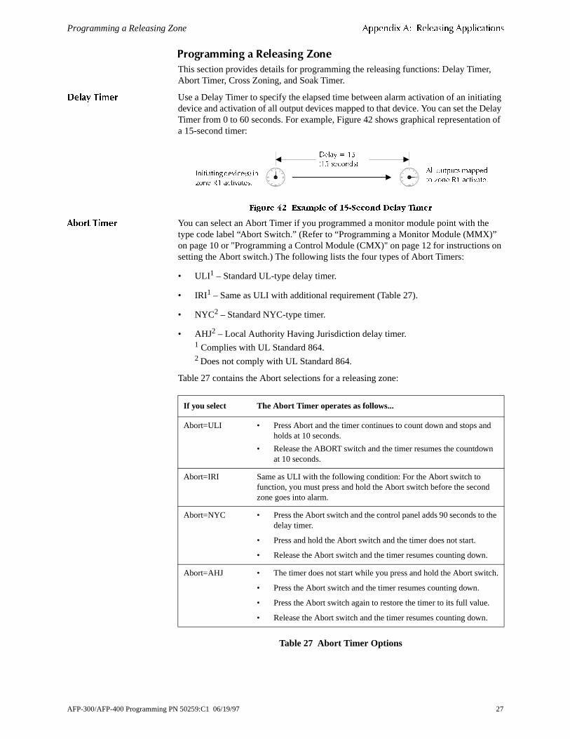
'HOD\ 7LPHU Use a Delay Timer to specify the elapsed time between alarm activation of an initiadevice and activation of all output devices mapped to that device. You can set the DTimer from 0 to 60 seconds. For example, Figure 42 shows graphical representatia 15-second timer:
)LJXUH �� ([DPSOH RI ���6HFRQG 'HOD\ 7LPHU
$ERUW 7LPHU You can select an Abort Timer if you programmed a monitor module point with thetype code label “Abort Switch.” (Refer to “Programming a Monitor Module (MMX)”on page 10 or "Programming a Control Module (CMX)" on page 12 for instructionssetting the Abort switch.) The following lists the four types of Abort Timers:
• ULI1 – Standard UL-type delay timer.
• IRI1 – Same as ULI with additional requirement (Table 27).
• NYC2 – Standard NYC-type timer.
• AHJ2 – Local Authority Having Jurisdiction delay timer.1 Complies with UL Standard 864.2 Does not comply with UL Standard 864.
Table 27 contains the Abort selections for a releasing zone:
Table 27 Abort Timer Options
0
15
30
45
0
15
30
45
'HOD\ ��
��� VHFRQGV�$OO RXWSXWV PDSSHG
WR ]RQH 5� DFWLYDWH�,QLWLDWLQJ GHYLFH�V� LQ
]RQH 5� DFWLYDWHV�
If you select The Abort Timer operates as follows...
Abort=ULI • Press Abort and the timer continues to count down and stops andholds at 10 seconds.
• Release the ABORT switch and the timer resumes the countdowat 10 seconds.
Abort=IRI Same as ULI with the following condition: For the Abort switch to function, you must press and hold the Abort switch before the secondzone goes into alarm.
Abort=NYC • Press the Abort switch and the control panel adds 90 seconds to delay timer.
• Press and hold the Abort switch and the timer does not start.
• Release the Abort switch and the timer resumes counting down.
Abort=AHJ • The timer does not start while you press and hold the Abort switc
• Press the Abort switch and the timer resumes counting down.
• Press the Abort switch again to restore the timer to its full value.
• Release the Abort switch and the timer resumes counting down.
AFP-300/AFP-400 Programming PN 50259:C1 06/19/97 27

$SSHQGL[ $� 5HOHDVLQJ $SSOLFDWLRQV Programming a Releasing Zone
any N.)
ing
ing
t ctors they
ones
es
&URVV =RQLQJ Cross Zoning lets you program the control panel to activate a releasing zone and output mapped to the releasing zone. (If not using Cross Zoning, set CROSS= to Table 28 summarizes the types of cross zoning and the conditions for activating areleasing zone.
Table 28 Cross Zoning Types
1RWH� 2QO\ WKH ILUVW QRQ�VSHFLDO
]RQH OLVWHG LQ WKH ]RQH PDS LV
XVHG WR GHWHUPLQH &URVV =�
&URVV =RQLQJ ([DPSOHV Table 29 contains examples of devices mapped to releaszones (ZR1 stands for Releasing Zone 1).
Table 29 Example: Devices Mapped to Releasing Zones
The following explanations apply to the examples listed in Table 29:
• Cross=N – An alarm from any detector activates the releasing circuit.
• Cross=Y – An alarm from any two detectors in the system activates the releascircuit.
• Cross=Z – Release requires the activation of two detectors mapped to differenzones: D101 and D102 cannot activate the releasing circuit because both deteare mapped to Z01; D101 and D103 can activate the releasing circuit becauseare mapped to different zones.
• Cross=H – Release requires activation of heat detector D104 and one smoke detector (D101, D102, or D103).
Type Activates when...
Y Two or more detectors are alarmed that are mapped to one of the ten releasing z(R0-R9).
Z Two or more detectors are alarmed that are mapped to two different software zonand mapped to one of the ten releasing zones (R0-R9).
H At least one smoke detector mapped to one of the ten releasing zones (R0-R9) isalarmed and at least one heat detector mapped to one of the ten releasing zones (R0-R9) is alarmed.
Device Address Device Type Zone Mapping
D101 Detector Smoke ZR1 Z01
D102 Detector Smoke ZR1 Z01
D103 Detector Smoke ZR1 Z02
D104 Detector Heat ZR1 Z02
B01 Output Circuit (Rel Ckt) ZR1
28 AFP-300/AFP-400 Programming PN 50259:C1 06/19/97

Programming a Releasing Zone $SSHQGL[ $� 5HOHDVLQJ $SSOLFDWLRQV
sing
oak
as
r;
as . h le
vice th g
pt lts
at
6RDN 7LPHU �1)3$ ��$SSOLFDWLRQV 2QO\�
The Soak Timer specifies the length of time (0000 to 9999 seconds) to dump releaagents when a zone activates. When the Soak Timer elapses, the control panel automatically shuts off the releasing solenoids for the active zone. To program a STimer for a point, follow these instructions:
6HOHFW 6RDN On the Release Function Screen, move the cursor to the Soak valueshown in Figure 43:
)LJXUH �� 6RDN 7LPHU 6HOHFWLRQ
(QWHU WKH 6RDN 7LPHU 9DOXH Enter a value for the Soak Timer: 0000=no Soak Timeor 0001-9999 seconds to select the amount of time for the Soak Timer.
6SHFLDO 0RGXOH 7\SHV You can program the following module type codes—which have special releasing functions—into the control panel.
Table 30 Special Releasing Device Types
35* 5(/($6( )81&7,21 5(/($6( &21752/
'(/$< �� $%257 8/, &5266 1 62$. ���� 5��
6RDN 7LPHU 9DOXH ��� VHFRQGV
Type Code Assigned to...
Abort Switch An MMX monitor module—connected to a listed abort station (such asthe Notifier ARA-10)—that performs abort functions. You can install multiple Abort Switch modules that provide a logical “or” function, like multiple conventional abort switches on a conventional zone.
Man. Release An MMX monitor module—connected to a listed manual station (suchthe Notifier ARA-10 or NBG-10) that performs a manual release functionA module programmed to Man. Release overrides all active Abort Switcmodules programmed to the same releasing zone. You can install multipMan. Release modules that provide a logical “or” function like multiple conventional release switches on a conventional zone.
Rel Ckt Ulc A CMX control module, or one of the four NACs on the panel, that activates a releasing solenoid or other releasing device. The release de—and all wiring to the release device—is fully supervised and usable wilimited energy cable. The release device activates when (a) an initiatindevice programmed to the same zone activates (two devices if cross-zoning is selected); and (b) the delay timer (if used) expires; and (c) noAbort Switch (if used) is active. Multiple Rel Ckt Ulc types may be programmed to the same releasing zone, and they all activate togetherwhen the zone becomes active.
Release Ckt A CMX control module that operates like a Rel Ckt Ulc module—excethe release device circuit is supervised for open circuits and ground fauonly. With this type code, do not use for the following:
• an application requiring ULC Listing or with limited energy cable;
• a REL-4.7K (panel output); or
• a REL-47K (CMX module).
Rel End Bell A CMX control module—supervised like a bell circuit—that activates when a releasing solenoid shuts off. This type code is always non-silenceable, and is only turned off by a System Reset. You must call outleast one or more releasing zones in the device's CBE.
1RWH� $OO 00; ZLULQJ IRU
VSHFLDO PRGXOH W\SHV LV IXOO\
VXSHUYLVHG� )RU LQVWUXFWLRQV�
UHIHU WR WKH $)3�����$)3����
,QVWDOODWLRQ 0DQXDO�
AFP-300/AFP-400 Programming PN 50259:C1 06/19/97 29

$SSHQGL[ $� 5HOHDVLQJ $SSOLFDWLRQV Programming a Releasing Zone
by ertain e 6
r to e
re
ny
,QLWLDWLQJ 'HYLFHV Releasing zone initiating devices include the following:
• FDX intelligent heat detectors;
• SDX, CPX, LPX, or IPX intelligent smoke detectors; or
• Conventional detection devices listed for the purpose and connected to MMX modules.
You can use multiple zone initiating devices for the same releasing hazard. Do somapping zone initiating devices to the same releasing zone. Factory Mutual and cLocal Authorities Having Jurisdiction require using redundant wiring (NFPA 72 Stylor Style D) for initiating devices in releasing applications.
:DUQLQJ 6RXQGHUV Warning sounders connect to any of the four panel Notification Appliance Circuits oCMX module circuits (refer to the AFP-300/AFP-400 Installation Manual). The samreleasing hazard can activate multiple Notification Appliance Circuits.
Table 31 Warning Sounder
$X[LOLDU\ &RQWURO)XQFWLRQV
Table 32 contains instructions for using control functions:
Table 32 Using Control Functions
$&6 $QQXQFLDWLRQ Table 33 contains instructions for annunciating ACS points and detectors:
Table 33 Annunciating ACS Points and Detectors
To activate a sounder... Do this....
When the delay timer starts, when the releasing device activates, or both.
Map the CMX module to a releasing hazard zone (R0-R9).
Immediately when one of the initiating devices activate.
Map the CMX to a separate zone (not R0-R9) that isalso mapped to all initiating devices of the hazard.
If... Do this...
A releasing application requires control relays
Use CMX modules set for dry contact operation. Program thecontrol relays for different functions by following the instructions in Table 31.
Providing control functions Use an ACM-8R remote relay module mapped to the softwazones of the control panel.
To Annunciate... Do this...
Points of releasing functions Select Annunciator Selection Group 1 or 2 to annunciate aof the software zones described above, including zones R0-R9. For instructions, refer to "Annunciator Options" on page19.
Individual detectors Select Annunciator Selection Group 6, 7, or 8. For instructions, refer to "Annunciator Options" on page 19.
� ,I VHOHFWLQJ FURVV�]RQLQJ�
WKLV VRXQGHU RQO\ DFWLYDWHV
ZKHQ WZR ]RQHV JR LQWR
DODUP�
� 8QOLNH UHOHDVH VROHQRLGV�
VRXQGHUV GR QRW ZDLW IRU
WKH GHOD\ WLPHU�
� ,I FRGHG VRXQGV DUH
UHTXLUHG IRU ZDUQLQJ
VRXQGHUV� WKH\ PXVW XVH
RQH RI WKH IRXU SDQHO
1RWLILFDWLRQ $SSOLDQFH
&LUFXLWV� QRW D &0; FLUFXLW�
30 AFP-300/AFP-400 Programming PN 50259:C1 06/19/97

ent
ns. If
es not
f a
nd an
fied on ed
F7 ime
$SSHQGL[�%��2XWSXWV
3UHVLJQDO�DQG�3RVLWLYH�$ODUP�6HTXHQFH��3$6�
The control panel delays activation of outputs containing F0 in their Control-By-Ev(CBE) equation for all alarm initiating devices that contain F0 in their Control-By-Event equation. A subsequent alarm will abort the delay and execute CBE equatiousing F0, note the following:
• Do not include F0 in the CBE equation for a releasing device.
• Abort circuit activation by pressing Alarm Silence before the delay expires.
3UHVLJQDO You can set Presignal delay time between 60 and 180 seconds. Presignal delay doapply to the following:
• the System Alarm relay (TB3 on the MPS-400);
• the 4XTM polarity reversal alarm output; and
• the 4XTM municipal box output.
3RVLWLYH $ODUP 6HTXHQFH�3$6�
Do not include F0 in the CBE equation for any monitor module that connects to a device other than an automatic fire detector. NFPA-72-1993 requires installation oPAS Inhibit switch. To do this, use a Monitor Module with type code PAS Inhibit.
Selected outputs delay for 15 seconds. Pressing Acknowledge within the 15-secodelay increases the delay to the full programmed value (60–180 seconds). When alarm comes from an initiating device—with a CBE equation that includes F0—thecontrol panel delays the following outputs:
• the System Alarm relay (TB3 on the MPS-400);
• the 4XTM Polarity Reversal Alarm output; and
• the 4XTM Municipal Box output.
7LPH�&RQWURO1RWH� $OO DFWLYH 7LPH &RQWURO
RXWSXWV ZLOO WXUQ RII WHPSRUDULO\
ZKLOH UHVHWWLQJ RU SURJUDPPLQJ
WKH FRQWURO SDQHO�
All outputs with a CBE equation containing F5 or F6 activate within the times specifor the days of the week listed in F5 or F6. All smoke detectors with a CBE equaticontaining F5 or F6 switch to their lowest sensitivity (AL:9) within the times specififor the days of the week listed in ZF5 or ZF6. Refer to “Appendix C: AWACS Applications” on page 33 for details on setting detector sensitivity.
Time Control is active for all days of the week listed in F5 or F6. Holidays listed in are excluded unless you list Holidays (H) in the day-of-week selection. Enter the tin a 24-hour format with the OFF time later than the ON time. After changing programming using Time Control, always reset the control panel.
AFP-300/AFP-400 Programming PN 50259:C1 06/19/97 31

$SSHQGL[ %� 2XWSXWV NAC Coding
are
Cs de ons:
1$&�&RGLQJ1RWH� 7KH FRQWURO SDQHODXWRPDWLFDOO\ VHQGV DQ DOHUWVLJQDO WR DQ\ RI WKH IRXU1RWLILFDWLRQ $SSOLDQFH &LUFXLWVPDSSHG WR =�� DQG )�� EXW QRWPDSSHG WR WKH DODUP VLJQDO�$IWHU � PLQXWHV ZLWKRXW DQ$FNQRZOHGJH RU 6LOHQFH� WKHDOHUW VLJQDO EHFRPHV VWHDG\�
Control panel Notification Appliance Circuits with a CBE equation that includes F8 coded when activated by a fire alarm. These circuits are steady when activated exclusively by an initiating device with a Hazard Alert Type Code. If using these NAfor releasing or zone coding, do not include F8 in the CBE equation. Select the cotype on a system basis, through special zone F8. Table 34 contains coding selecti
Table 34 NAC Coding Selections
Code Signal
March Time (default) 120 PPM (Pulses Per Minute)
Two-Stage Alert signal – 20 PPM; General alarm signal: Steady on
California 10 sec. on, 5 sec. off, repeats
Temporal 0.5 on, 0.5 off, 0.5 on, 0.5 off, 0.5 on, 1.5 off, repeats
32 AFP-300/AFP-400 Programming PN 50259:C1 06/19/97

are on y the
ons
sate , dirt tector
cally .
ise re
.
$SSHQGL[�&��$:$&6�$SSOLFDWLRQV
$:$&6�2YHUYLHZ
AWACS™ (Advanced Warning Addressable Combustion Sensing) is a set of softwalgorithms that provide the AFP-300/AFP-400 with industry-leading smoke detecticapability. The development of these sophisticated algorithms are made possible bclose cooperation between Notifier and System Sensor, the world leaders in fire detection and alarm technology. These complex algorithms require many calculation each reading of each detector, and are made possible by the very high speed microcomputer used by the AFP-300/AFP-400. Appendix C covers the following topics:
Table 35 AWACS Topics
$:$&6�)HDWXUHV
AWACS features include the following:
• Drift Compensation and Smoothing
• Maintenance Warnings
• Sensitivity Adjust
• Self-optimizing Pre-Alarm
• Cooperating Multi-Detector Sensing
• Pre-Alarm
'ULIW &RPSHQVDWLRQ DQG6PRRWKLQJ
Drift compensation uses algorithms (U.S. patent pending) that identify and compenfor long-term changes in the analog readings from each smoke sensor. (Typicallyand dust accumulation inside the smoke chamber causes long-term changes in dereadings.) Drift compensation does the following:
• Allows a detector to retain its original ability to detect actual smoke, and resistfalse alarms, even as dirt and dust accumulates.
• Reduces maintenance requirements by allowing the control panel to automatiperform the periodic sensitivity measurements required by NFPA Standard 72
AFP-300/AFP-400 software also provides smoothing filters to remove transient nosignals, usually caused by electrical interference. Different smoothing algorithms aused, depending on the sensitivity selection of each detector. Refer to “Detector Sensitivity Settings” on page 39 for more information on detector sensitivity levels
Topic Refer to Page...
$:$&6 IHDWXUHV – Descriptions of AWACS features, such as Drift Compensation, Sensitivity Adjust, and so on.
33
3UH�$ODUP – Alert and Action settings, programming 38
'HWHFWRU 6HQVLWLYLW\ 6HWWLQJV – Pre-Alarm and Alarm sensitivity settings for photo, ion, laser, and multisensor detectors.
39
'HWHFWRU 0DLQWHQDQFH )HDWXUHV – Instructions for viewing and printing detector maintenance information.
41
AFP-300/AFP-400 Programming PN 50259:C1 06/19/97 33

$SSHQGL[ &� $:$&6 $SSOLFDWLRQV AWACS Features
ft
aches arizes
Figure 44 contains a graphic representation of a detector analog reading using dricompensation and smoothing:
)LJXUH �� *UDSKLF 5HSUHVHQWDWLRQ RI 'ULIW &RPSHQVDWLRQ
0DLQWHQDQFH :DUQLQJV² 7KUHH /HYHOV
The software determines when the drift compensation for a detector reaches an unacceptable level that can compromise detector performance. When a detector rean unacceptable level, the software gives a maintenance warning. Table 36 summthe three levels of AWACS maintenance warnings:
Table 36 Definitions of AWACS Maintenance Levels
Figure 45 contains a graphic representation of the maintenance levels:
)LJXUH �� 'LDJUDP RI 0DLQWHQDQFH /HYHOV
Maintenance Level Indicates...
Low Chamber value a hardware problem in the detector.
Maintenance Alert dust accumulation that is near but below the allowed limit.
Maintenance Urgent dust accumulation above the allowed limit. The Maintenance Alert level allows maintenance beforethe performance of the device is compromised.
34 AFP-300/AFP-400 Programming PN 50259:C1 06/19/97

AWACS Features $SSHQGL[ &� $:$&6 $SSOLFDWLRQV
the g the
ay/
t
l
6HOI�2SWLPL]LQJ3UH�$ODUP
Each detector [except FDX (Heat)] may be set for Self-Optimizing Pre-Alarm (PA=1). In this Self-Optimizing mode, a detector learns its normal environment, assoftware measures the peak analog readings over a long period of time, and settinPre-Alarm level just above these normal peaks. This allows extremely sensitive Pre-Alarm capability with reasonable protection against non-fire signals. Figure 46shows a graphical representation of the Self-Optimizing Pre-Alarm level:
)LJXUH �� 6HOI�RSWLPL]LQJ 3UH�$ODUP /HYHO
For more information on setting Pre-Alarm levels, refer to the following sections:
• "Detector Sensitivity" on page 22.
• "Selecting Detector Sensitivity" on page 22.
6HQVLWLYLW\ /HYHOV The control panel provides nine Sensitivity Levels for alarm detection—down to approximately 0.03% per foot obscuration (for laser detectors used in a very cleanenvironment only). You can set the Sensitivity Levels as fixed or programmed for DNight operation. For details, refer to "Time Control" on page 31.
1RWH� )RU D OLVW RI DOO GHWHFWRU
VHQVLWLYLW\ OHYHOV� VHH 7DEOH ��
RQ SDJH ���
• 'HWHFWRU 6HQVLWLYLW\ /HYHOV Set the sensitivity of a detector from 1-9 (1=highessensitivity; 9=lowest sensitivity).
• 3UH�$ODUP 6HQVLWLYLW\ /HYHOV Nine levels from 1 to 9 (0=no Pre-Alarm, 1=self-optimizing, 2=highest sensitivity, 9=lowest sensitivity). You can set Pre-Alarm operation to latching or self-restoring and to activate Special ControFunctions.
1RWH� 3$�� QR 3UH�$ODUP Figure 47 shows a sample sensitivity window for a laser detector:
)LJXUH �� 6HQVLWLYLW\ /HYHOV IRU D /DVHU 'HWHFWRU
AFP-300/AFP-400 Programming PN 50259:C1 06/19/97 35
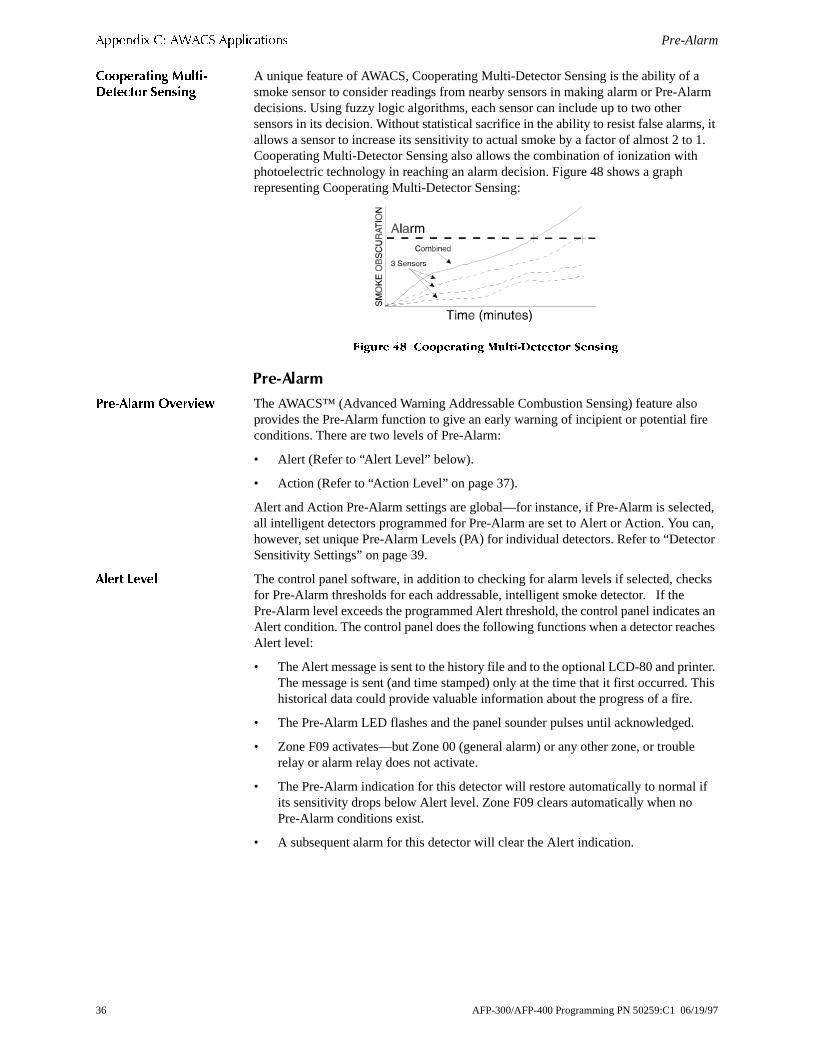
$SSHQGL[ &� $:$&6 $SSOLFDWLRQV Pre-Alarm
larm
s, it 1.
o e
ted, an, ctor
cks
es an ches
nter. This
.
e
if
&RRSHUDWLQJ 0XOWL�'HWHFWRU 6HQVLQJ
A unique feature of AWACS, Cooperating Multi-Detector Sensing is the ability of asmoke sensor to consider readings from nearby sensors in making alarm or Pre-Adecisions. Using fuzzy logic algorithms, each sensor can include up to two other sensors in its decision. Without statistical sacrifice in the ability to resist false alarmallows a sensor to increase its sensitivity to actual smoke by a factor of almost 2 toCooperating Multi-Detector Sensing also allows the combination of ionization withphotoelectric technology in reaching an alarm decision. Figure 48 shows a graph representing Cooperating Multi-Detector Sensing:
)LJXUH �� &RRSHUDWLQJ 0XOWL�'HWHFWRU 6HQVLQJ
3UH�$ODUP
3UH�$ODUP 2YHUYLHZ The AWACS™ (Advanced Warning Addressable Combustion Sensing) feature alsprovides the Pre-Alarm function to give an early warning of incipient or potential firconditions. There are two levels of Pre-Alarm:
• Alert (Refer to “Alert Level” below).
• Action (Refer to “Action Level” on page 37).
Alert and Action Pre-Alarm settings are global—for instance, if Pre-Alarm is selecall intelligent detectors programmed for Pre-Alarm are set to Alert or Action. You chowever, set unique Pre-Alarm Levels (PA) for individual detectors. Refer to “DeteSensitivity Settings” on page 39.
$OHUW /HYHO The control panel software, in addition to checking for alarm levels if selected, chefor Pre-Alarm thresholds for each addressable, intelligent smoke detector. If the Pre-Alarm level exceeds the programmed Alert threshold, the control panel indicatAlert condition. The control panel does the following functions when a detector reaAlert level:
• The Alert message is sent to the history file and to the optional LCD-80 and priThe message is sent (and time stamped) only at the time that it first occurred.historical data could provide valuable information about the progress of a fire.
• The Pre-Alarm LED flashes and the panel sounder pulses until acknowledged
• Zone F09 activates—but Zone 00 (general alarm) or any other zone, or troublrelay or alarm relay does not activate.
• The Pre-Alarm indication for this detector will restore automatically to normal its sensitivity drops below Alert level. Zone F09 clears automatically when no Pre-Alarm conditions exist.
• A subsequent alarm for this detector will clear the Alert indication.
36 AFP-300/AFP-400 Programming PN 50259:C1 06/19/97

Pre-Alarm $SSHQGL[ &� $:$&6 $SSOLFDWLRQV
5 s at e r and own
, a
at
isplay tions
and
fth
n). on or
even
$OHUW /HYHO ([DPSOH� For example, if you program an ion detector for AL:7 and PA:(covered in "Selecting Detector Sensitivity" on page 22), an Alert Pre-Alarm occurmeasured smoke detector levels that exceed 1.00% per foot obscuration. When thsmoke level of this detector exceeds 1.00% per foot obscuration, the panel soundePre-Alarm Warning LED pulse, and a panel display similar to the sample screen shin Figure 49 appears:
)LJXUH �� 6DPSOH 'LVSOD\ RI DQ $OHUW &RQGLWLRQ
1RWH� 7R VLOHQFH D SDQHOVRXQGHU� SUHVV WKH $FNQRZOHGJHVZLWFK RQ WKH FRQWURO SDQHO�
If viewing the Pre-Alarm level of the same detector using the Read Status functionpanel display similar to the sample screen in Figure 50 appears:
)LJXUH �� 6DPSOH 'LVSOD\ RI DQ $OHUW &RQGLWLRQ �5HDG 6WDWXV�
$FWLRQ /HYHO If you program a detector for Action Pre-Alarm and the detector reaches a level thexceeds the programmed Pre-Alarm level, the control panel indicates an Action condition. Figure 51 shows a sample Action message that appears on the panel dwhen a detector reaches an Action level. The control panel does the following funcwhen a detector reaches the programmed Action level:
• The Pre-Alarm LED and panel sounder pulse until acknowledged.
• Zone F09 is activated—but Zone Z00 (general alarm) and the MPS-400 troublealarm relays do not activate.
• The fifth zone programmed (not the first four) for this detector activates. The fizone is the right-most entry on line two of the detector CBE in the point programming screen (refer to the programming manual for detailed informatioThis zone may be used to control functions of a detector or group of detectorsAction level. Fifth zone activations also allow ACS annunciation by a detector group of detectors in Action Pre-Alarm condition.
• The Pre-Alarm condition and the zone programmed latch until System Reset, if the sensitivity drops below the Action level.
• A subsequent alarm condition for this detector clears the Action indication fromthe panel display alarm list.
)LJXUH �� 6DPSOH 'LVSOD\ RI D 3UH�$ODUP $FWLRQ &RQGLWLRQ
3UH�$ODUP VWDWXV EDQQHU
������ LQGLFDWHV WKDW ���� RI3UH�$ODUP OHYHO � LV UHDFKHG�
$/(57 LQGLFDWHV WKDW WKH $OHUW3UH�$ODUP OHYHO LV UHDFKHG�
35($/0 602.( �,21� '(7(&725 $''5 ���
$/(57� ������ �����$ �������� '���
3UH�$ODUP VWDWXV EDQQHU
����$� LQGLFDWHV WKDW ��� RI $/�� LV UHDFKHG�ZKLFK HTXDOV WKH 3UH�$ODUP OHYHO RI 3$�� �VHH7DEOH �� RQ SDJH ����
35($/0 602.( �,21� '(7(&725 $''5 ���
=�� = = = = ����$� 3$�� '���
3UH�$ODUP VWDWXV EDQQHU
35($/0 602.( �,21� '(7(&725 $''5 ���
$&7,21� ������ �����$ �������� '���
������ LQGLFDWHV WKDW WKH $FWLRQ3UH�$ODUP OHYHO LV UHDFKHG�
AFP-300/AFP-400 Programming PN 50259:C1 06/19/97 37

$SSHQGL[ &� $:$&6 $SSOLFDWLRQV Selecting a Pre-Alarm Level
t or
6HOHFWLQJ�D�3UH�$ODUP�/HYHO�
Table 37 contains instructions and sample displays to program Pre-Alarm for AlerAction:
Table 37 Programming a Pre-Alarm Level (Alert or Action)
Do this... And the control panel displays...
1. Access the Program Change screen by entering the Program Change password from the Enter Password Screen (Figure 4 on page 5).
2. From the Program Change screen, select 6=Spl Funct to display the Special Function Zone Change screen.
3. From the Special Function Zone Change screen, select F9=Pre-Alarm, to display the Pre-Alarm Function screen with Alert blinking.
4. To select Action, press the
/ or 0 key.
� &/5 � $872 � 32,17 � 3$66:' � 0(66$*(
� =21(6 � 63/ )81&7 � 6<67(0 � &+(&. 35*
6HOHFW � 63/ )81&7
63(&,$/ )81&7,21� )� 35(6,* 5��5� 5(/
)��)� 7,0( )� +2/ )� &2'( )� 35(�$/$50
6HOHFW )� 35(�$/$50
35* 35(/$50 )81&7 $/(57
)��
$/(57 EOLQNLQJ
35* 35(/$50 )81&7 $&7,21
)��
$&7,21 EOLQNLQJ
1RWH� ,I XVLQJ $&6 DQQXQFLDWLRQ
2QO\ WKH $FWLRQ OHYHO ZLOO
SURYLGH $&6 SRLQW
DQQXQFLDWLRQ�
38 AFP-300/AFP-400 Programming PN 50259:C1 06/19/97
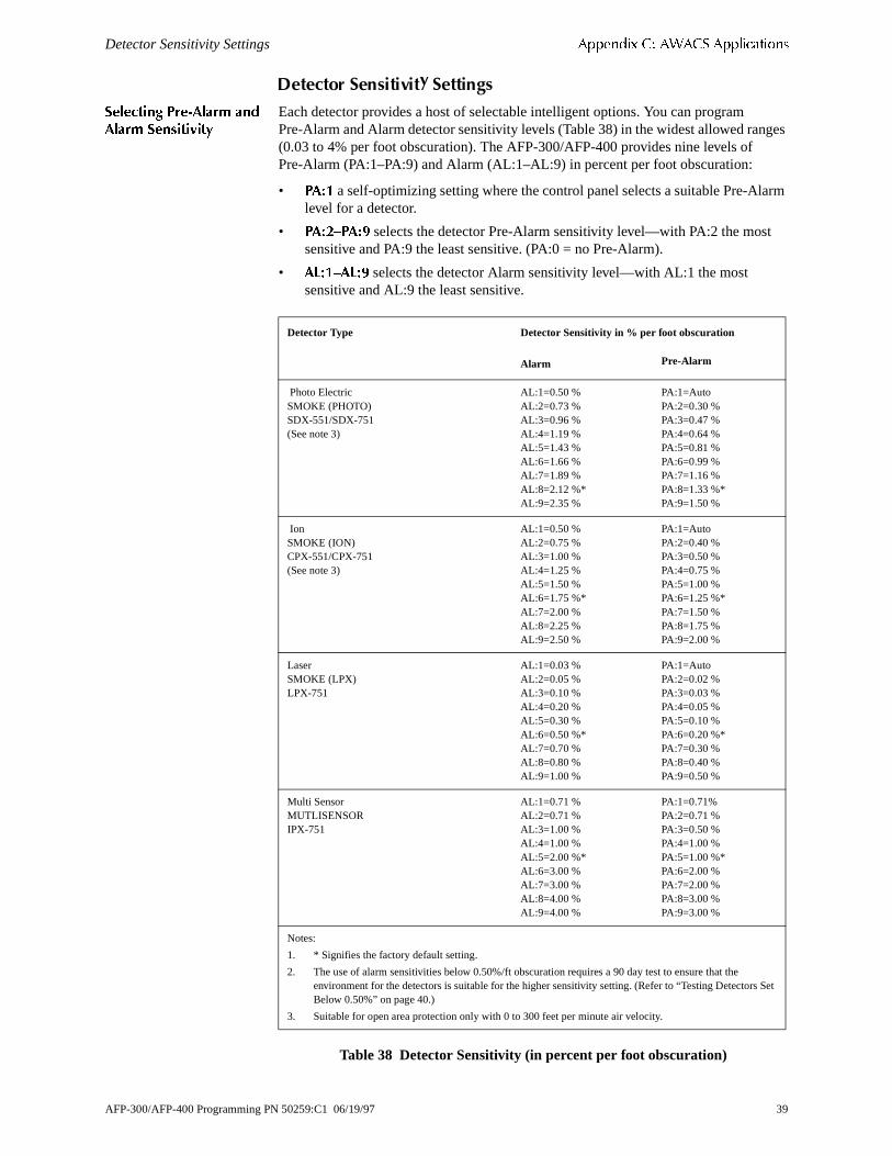
Detector Sensitivity Settings $SSHQGL[ &� $:$&6 $SSOLFDWLRQV
ges
arm
t
et
'HWHFWRU�6HQVLWLYLW\�6HWWLQJV
6HOHFWLQJ 3UH�$ODUP DQG$ODUP 6HQVLWLYLW\
Each detector provides a host of selectable intelligent options. You can program Pre-Alarm and Alarm detector sensitivity levels (Table 38) in the widest allowed ran(0.03 to 4% per foot obscuration). The AFP-300/AFP-400 provides nine levels of Pre-Alarm (PA:1–PA:9) and Alarm (AL:1–AL:9) in percent per foot obscuration:
• 3$�� a self-optimizing setting where the control panel selects a suitable Pre-Allevel for a detector.
• 3$��²3$�� selects the detector Pre-Alarm sensitivity level—with PA:2 the mossensitive and PA:9 the least sensitive. (PA:0 = no Pre-Alarm).
• $/��²$/�� selects the detector Alarm sensitivity level—with AL:1 the most sensitive and AL:9 the least sensitive.
Table 38 Detector Sensitivity (in percent per foot obscuration)
Detector Type Detector Sensitivity in % per foot obscuration
Alarm Pre-Alarm
Photo Electric SMOKE (PHOTO)SDX-551/SDX-751(See note 3)
AL:1=0.50 %AL:2=0.73 %AL:3=0.96 %AL:4=1.19 %AL:5=1.43 %AL:6=1.66 %AL:7=1.89 %AL:8=2.12 %*AL:9=2.35 %
PA:1=AutoPA:2=0.30 %PA:3=0.47 %PA:4=0.64 %PA:5=0.81 %PA:6=0.99 %PA:7=1.16 %PA:8=1.33 %*PA:9=1.50 %
IonSMOKE (ION)CPX-551/CPX-751(See note 3)
AL:1=0.50 %AL:2=0.75 %AL:3=1.00 %AL:4=1.25 %AL:5=1.50 %AL:6=1.75 %*AL:7=2.00 %AL:8=2.25 %AL:9=2.50 %
PA:1=Auto PA:2=0.40 %PA:3=0.50 %PA:4=0.75 %PA:5=1.00 %PA:6=1.25 %*PA:7=1.50 %PA:8=1.75 %PA:9=2.00 %
LaserSMOKE (LPX)LPX-751
AL:1=0.03 %AL:2=0.05 %AL:3=0.10 %AL:4=0.20 %AL:5=0.30 %AL:6=0.50 %*AL:7=0.70 %AL:8=0.80 %AL:9=1.00 %
PA:1=AutoPA:2=0.02 %PA:3=0.03 %PA:4=0.05 %PA:5=0.10 %PA:6=0.20 %*PA:7=0.30 %PA:8=0.40 %PA:9=0.50 %
Multi SensorMUTLISENSORIPX-751
AL:1=0.71 %AL:2=0.71 %AL:3=1.00 %AL:4=1.00 %AL:5=2.00 %*AL:6=3.00 %AL:7=3.00 %AL:8=4.00 %AL:9=4.00 %
PA:1=0.71%PA:2=0.71 %PA:3=0.50 %PA:4=1.00 %PA:5=1.00 %*PA:6=2.00 %PA:7=2.00 %PA:8=3.00 %PA:9=3.00 %
Notes:
1. * Signifies the factory default setting.
2. The use of alarm sensitivities below 0.50%/ft obscuration requires a 90 day test to ensure that the environment for the detectors is suitable for the higher sensitivity setting. (Refer to “Testing Detectors SBelow 0.50%” on page 40.)
3. Suitable for open area protection only with 0 to 300 feet per minute air velocity.
AFP-300/AFP-400 Programming PN 50259:C1 06/19/97 39
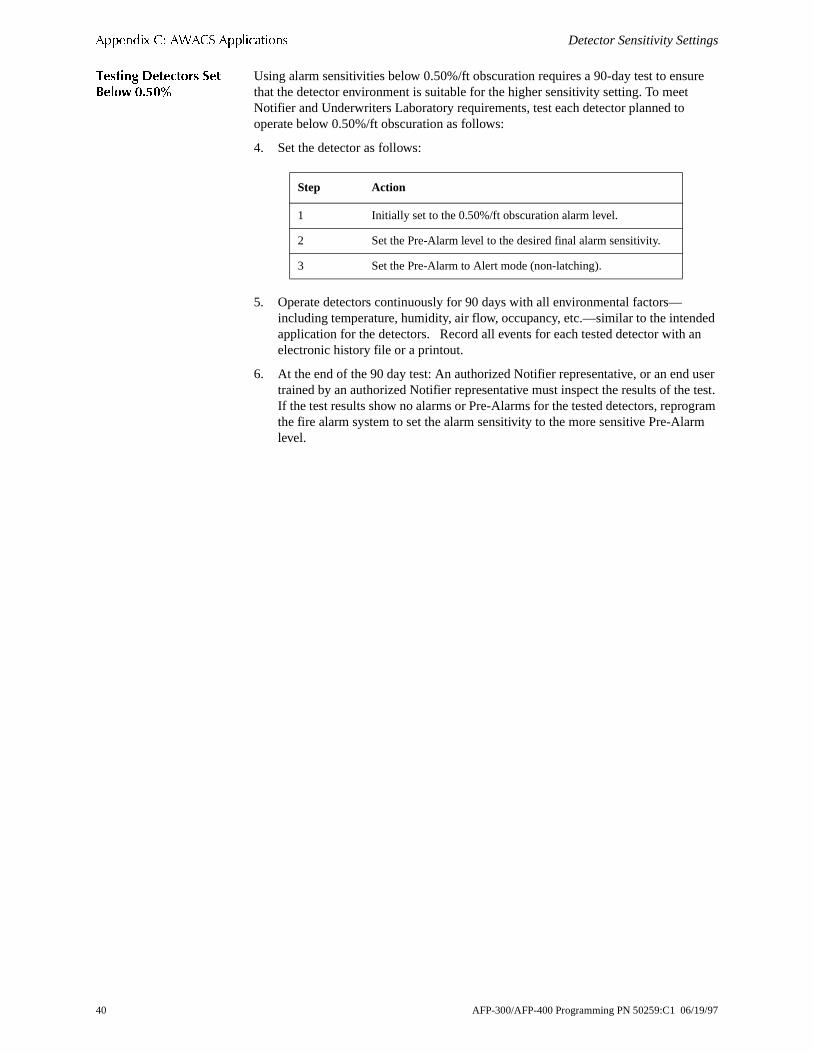
$SSHQGL[ &� $:$&6 $SSOLFDWLRQV Detector Sensitivity Settings
ure
ed an
user test. gram rm
7HVWLQJ 'HWHFWRUV 6HW%HORZ �����
Using alarm sensitivities below 0.50%/ft obscuration requires a 90-day test to ensthat the detector environment is suitable for the higher sensitivity setting. To meet Notifier and Underwriters Laboratory requirements, test each detector planned to operate below 0.50%/ft obscuration as follows:
4. Set the detector as follows:
5. Operate detectors continuously for 90 days with all environmental factors—including temperature, humidity, air flow, occupancy, etc.—similar to the intendapplication for the detectors. Record all events for each tested detector with electronic history file or a printout.
6. At the end of the 90 day test: An authorized Notifier representative, or an endtrained by an authorized Notifier representative must inspect the results of theIf the test results show no alarms or Pre-Alarms for the tested detectors, reprothe fire alarm system to set the alarm sensitivity to the more sensitive Pre-Alalevel.
Step Action
1 Initially set to the 0.50%/ft obscuration alarm level.
2 Set the Pre-Alarm level to the desired final alarm sensitivity.
3 Set the Pre-Alarm to Alert mode (non-latching).
40 AFP-300/AFP-400 Programming PN 50259:C1 06/19/97

Detector Maintenance Features $SSHQGL[ &� $:$&6 $SSOLFDWLRQV
level
plays
us for
re 54
'HWHFWRU�0DLQWHQDQFH�)HDWXUHV
2YHUYLHZ The AFP-300/AFP-400 provides features to check the maintenance performance of addressable, intelligent detectors. Detector maintenance features include the following:
• View detector maintenance information for an individual detector (Figure 54).
• Print a detector maintenance report for all detectors (Figure 55).
$FFHVVLQJ 'HWHFWRU0DLQWHQDQFH,QIRUPDWLRQ
Access detector maintenance functions by pressing <Enter>. The control panel disthe Program Entry screen.
)LJXUH �� 3URJUDP (QWU\ 6FUHHQ
From the Program Entry screen, press P; then, press 5. The control panel displays the Detector Maintenance Selection Screen (Figure 54).
)LJXUH �� 'HWHFWRU 0DLQWHQDQFH 6HOHFWLRQ 6FUHHQ
9LHZLQJ 'HWHFWRU0DLQWHQDQFH IRU D'HWHFWRU
From the Detector Maintenance Selection Screen, you can view Maintenance Stata detector by doing the following: Press +; enter the detector address; then, press <Enter>. The control panel displays the Detector Maintenance Status Screen. Figushows a sample Detector Maintenance Status screen for a laser detector. Refer to“Interpreting a Detector Status Display or Maintenance Report” on page 42 for descriptions of each item.
)LJXUH �� 'HWHFWRU 0DLQWHQDQFH 6WDWXV 6FUHHQ
� 352*5$00,1* � 5($' 67$786 (175<
�(6&$3( 72 $%257�
6HOHFW 'HWHFWRU $GGUHVV �'[[[� �(17(5!
RU 3UHVV �� �(17(5! IRU SULQW DOO�
'HWHFWRU DGGUHVV >6/& QR��
GHYLFH DGGUHVV �������@�
3UHVV �� WKHQ� SUHVV �(QWHU! WR SULQW D 'HWHFWRU
0DLQWHQDQFH 5HSRUW �)LJXUH �� RQ SDJH ����
3UHVV '� W\SH WKH GHWHFWRU DGGUHVV� WKHQ
SUHVV �(QWHU!�
1RUPDO 6PRNH�/$6(5� 'HWHFWRU $''5 ���
&RPS����� 3N������ ����$� 3$�� $ '���
$ODUP 9HULILFDWLRQ VHOHFWLRQ
3HDN YDOXH ² WKH KLJKHVW DODUP
OHYHO UHDFKHG LQ WKH SDVW ZHHN
���FKDUDFWHU FXVWRP ODEHO
&XUUHQW $ODUP UHDGLQJ �SHUFHQWDJH RI DODUP�
3UH�$ODUP VHQVLWLYLW\ VHWWLQJ
�� QRQH� ����
0XOWL�'HWHFWRU VHOHFWLRQ
3HUFHQWDJH RI GULIW
FRPSHQVDWLRQ
$ODUP VHQVLWLYLW\ VHWWLQJ �����
'HYLFH 6WDWXV
$GGUHVV �6/& QXPEHU�
GHYLFH DGGUHVV �������
7\SH &RGH
' DGGUHVV SUHIL[ �LQGLFDWHV D
GHWHFWRU�
1RWH� 2QFH \RX GLVSOD\
LQIRUPDWLRQ IRU D GHWHFWRU� \RX
FDQ XVH WKH0 DQG/ NH\V
WR YLHZ LQIRUPDWLRQ IRU WKH QH[W
RU SUHYLRXV GHWHFWRU RQ WKH 6/&�
AFP-300/AFP-400 Programming PN 50259:C1 06/19/97 41
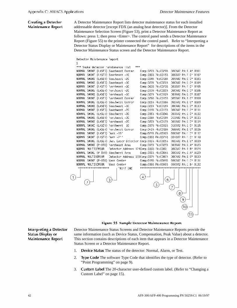
$SSHQGL[ &� $:$&6 $SSOLFDWLRQV Detector Maintenance Features
d
s ance ng a e
the tector. ance
to
g a
&UHDWLQJ D 'HWHFWRU0DLQWHQDQFH 5HSRUW
A Detector Maintenance Report lists detector maintenance status for each installeaddressable detector [except FDX (an analog heat detector)]. From the Detector Maintenance Selection Screen (Figure 53), print a Detector Maintenance Report afollows: press 1; then press <Enter>. The control panel sends a Detector MaintenReport (Figure 55) to the printer connected the control panel. Refer to “InterpretiDetector Status Display or Maintenance Report” for descriptions of the items in thDetector Maintenance Status screen and the Detector Maintenance Report.
)LJXUH �� 6DPSOH 'HWHFWRU 0DLQWHQDQFH 5HSRUW
,QWHUSUHWLQJ D 'HWHFWRU6WDWXV 'LVSOD\ RU0DLQWHQDQFH 5HSRUW
Detector Maintenance Status Screens and Detector Maintenance Reports providesame information (such as Device Status, Compensation, Peak Value) about a deThis section contains descriptions of each item that appears in a Detector MaintenStatus Screen or a Detector Maintenance Report.
1. 'HYLFH 6WDWXV The status of the detector: Normal, Alarm, or Test.
2. 7\SH &RGH The software Type Code that identifies the type of detector. (Refer “Point Programming” on page 9).
3. &XVWRP /DEHO The 20-character user-defined custom label. (Refer to “ChanginCustom Label” on page 15).
'HWHFWRU 0DLQWHQDQFH 5HSRUW
�
6PRNH GHWHFWRU PDLQWHQDQFH OLVW
1250$/ 602.( �/$6(5� 6RXWKHDVW &RUQHU &RPS����� 3N������ ����$� 3$�� $ '���
1250$/ 602.( �/$6(5� 6RXWKHDVW ��� &RPS����� 3N������ ����$� 3$�� & '���
1250$/ 602.( �/$6(5� 6RXWKHDVW ��� &RPS����� 3N������ ����$� 3$�� & '���
1250$/ 602.( �/$6(5� 6RXWKHDVW ��� &RPS����� 3N������ ����$� 3$�� & '���
1250$/ 602.( �/$6(5� 1RUWKHDVW ��� &RPS����� 3N������ ����$� 3$�� & '���
1250$/ 602.( �/$6(5� 1RUWKHDVW ��� &RPS����� 3N������ ����$� 3$�� & '���
1250$/ 602.( �/$6(5� 1RUWKHDVW ��� &RPS����� 3N������ ����$� 3$�� & '���
1250$/ 602.( �/$6(5� 1RUWKHDVW &RUQHU &RPS����� 3N������ ����$� 3$�� & '���
1250$/ 602.( �/$6(5� 6RXWKZHVW &RUQHU &RPS����� 3N������ ����$� 3$�� & '���
1250$/ 602.( �/$6(5� 6RXWKZHVW ��� &RPS����� 3N������ ����$� 3$�� & '���
1250$/ 602.( �/$6(5� 6RXWKZHVW ��� &RPS����� 3N������ ����$� 3$�� & '���
1250$/ 602.( �/$6(5� 6RXWKZHVW ��� &RPS����� 3N������ ����$� 3$�� & '���
1250$/ 602.( �/$6(5� 1RUWKZHVW ��� &RPS����� 3N������ ����$� 3$�� & '���
1250$/ 602.( �/$6(5� 1RUWKZHVW ��� &RPS����� 3N������ ����$� 3$�� & '���
1250$/ 602.( �/$6(5� 1RUWKZHVW ��� &RPS����� 3N������ ����$� 3$�� & '���
1250$/ 602.( �/$6(5� 1RUWKZHVW &RUQHU &RPS����� 3N������ ����$� 3$�� & '���
1250$/ 602.( �/$6(5� 'XFW ���· &RPS����� 3N������ ����$� 3$�� & '���
1250$/ 602.( �/$6(5� 'XFW ��·· &RPS����� 3N������ ����$� 3$�� & '���
1250$/ 602.( �/$6(5� 'XFW /DVHU 'HWHFWRU &RPS����� 3N������ ����$� 3$�� & '���
1250$/ 602.( �3+272� 1RUWKHDVW $UHD &RPS����� 3N������ ����$� 3$�� $ '���
1250$/ 08/7,6(1625 'HWHFWRU $GGUHVV ���&RPS����� 3N����� ����$� 3$�� % '���
1250$/ 602.( �3+272� 6RXWKZHVW $UHD &RPS����� 3N������ ����$� 3$�� $ '���
1250$/ 08/7,6(1625 'HWHFWRU $GGUHVV ���&RPS����� 3N������ ����$� 3$�� & '���
1250$/ 602.( �3+272� :HVW &HQWHU &RPS����� 3N������ ����$� 3$�� & '���
1250$/ 08/7,6(1625 :HVW &HQWHU &RPS����� 3N������ ����$� 3$�� % '���
35,17 (1'
��
��
�
��
�
�
�
�
�
�
42 AFP-300/AFP-400 Programming PN 50259:C1 06/19/97

Detector Maintenance Features $SSHQGL[ &� $:$&6 $SSOLFDWLRQV
d s, uires or d
the
on
r to rm
t ns. ith
he
larm
r a
4. 'ULIW &RPSHQVDWLRQ �&RPS�� The relative cleanliness of a detector determineby sampling the amount of contaminants in the detector, ambient air conditionand the age of the detector. The COMP value also indicates if a detector reqmaintenance. Refer to “Maintenance Warnings – Three Levels” on page 34 fdefinitions of maintenance levels. See Table 39 for a list of the normal level anmaintenance level values for each type of detector:
Table 39 Maintenance Levels by Detector Type
5. 3HDN 9DOXH (0000%) The highest analog value reached by the detector during past week. The peak value slowly returns to zero.
6. $ODUP 5HDGLQJ �[[[�� The current alarm reading of the detector.
7. $ODUP 6HQVLWLYLW\ 6HWWLQJ �$[� The Alarm Sensitivity (x=1-9) entered in the Detector Sensitivity Screen (Figure 35). Refer to “Detector Sensitivity Settings”page 39 for more information on the Alarm Sensitivity settings.
8. 3UH�$ODUP 6HQVLWLYLW\ 6HWWLQJ �3$�[� The Pre-Alarm Sensitivity (1-9; 0 = Pre-Alarm not used) entered in the Detector Settings Screen (Figure 35). Refe“Detector Sensitivity Settings” on page 39 for more information on the Pre-Alaalarm sensitivity settings.
9. &RRSHUDWLYH 0XOWL�'HWHFWRU 6HOHFWLRQA smoke detector programmed so that ievaluates readings from nearby sensors in making Alarm or Pre-Alarm decisioCooperative Multi-Detector sensing also allows the combination of ionization wphotoelectric technology in reaching an alarm decision.
1RWH� 5HIHU WR 7DEOH � IRU
LQVWUXFWLRQV RQ VHWWLQJ
&RRSHUDWLYH 0XOWL�'HWHFWRU
6HWWLQJV�
* – Multi-not used.
A – combines the detector’s alarm decision with the next address above.
B– combines the detector’s alarm decision with the next address below.
C – combines the detector’s alarm decision with the next address above and tnext address below.
10. $ODUP 9HULILFDWLRQ � RU 9[[�* – Alarm Verification not programmed for this detector. xx – Alarm Verification programmed for the detector; xx equals the verificationcounter (00-99). Refer to Table 8 on page 7 for instructions on setting Alarm Verification.
Alarm Verification is a user-defined global time function (set using option 7, System) that can reduce the number of nuisance alarms. When you select AVerification for a detector, the control panel delays an alarm signal for a user-specified time period. (The control panel ignores the Alarm Verification Timer if it detects another alarm during the verification period.)
11. 'HYLFH $GGUHVV The address of the detector. Refer to Figure 54 on page 41 focomplete description.
Type of Detector
NormalLow Chamber Reading
Maint. Alert Maint. Urgent
Ion 006-068 less than 006 92-99 100
Photo 006-069 less than 006 93-99 100
Laser 003-063 less than 003 83-99 100
Multisensor 024-040 less than 024 80-99 100
AFP-300/AFP-400 Programming PN 50259:C1 06/19/97 43

NOTIFIER® warrants its products to be free from defects in materials and workmanshipfor eighteen (18) months from the date of manufacture, under normal use and service.Products are date stamped at time of manufacture. The sole and exclusive obligationof NOTIFIER® is to repair or replace, at its option, free of charge for parts and labor,any part which is defective in materials or workmanship under normal use and service.For products not under NOTIFIER® manufacturing date-stamp control, the warrantyis eighteen (18) months from date of original purchase by NOTIFIER®'s distributorunless the installation instructions or catalog sets forth a shorter period, in whichcase the shorter period shall apply. This warranty is void if the product is altered,repaired or serviced by anyone other than NOTIFIER® or its authorized distributors orif there is a failure to maintain the products and systems in which they operate in aproper and workable manner. In case of defect, secure a Return Material Authorizationform from our customer service department. Return product, transportation prepaid,to NOTIFIER®, 12 Clintonville Road, Northford, Connecticut 06472-1653.
This writing constitutes the only warranty made by NOTIFIER® with respect to itsproducts. NOTIFIER® does not represent that its products will prevent any loss byfire or otherwise, or that its products will in all cases provide the protection for whichthey are installed or intended. Buyer acknowledges that NOTIFIER® is not an insurerand assumes no risk for loss or damages or the cost of any inconvenience,transportation, damage, misuse, abuse, accident or similar incident.
NOTIFIER® GIVES NO WARRANTY, EXPRESSED OR IMPLIED, OFMERCHANTABILITY, FITNESS FOR ANY PARTICULAR PURPOSE, OROTHERWISE WHICH EXTEND BEYOND THE DESCRIPTION ON THE FACEHEREOF. UNDER NO CIRCUMSTANCES SHALL NOTIFIER® BE LIABLE FOR ANYLOSS OF OR DAMAGE TO PROPERTY, DIRECT, INCIDENTAL ORCONSEQUENTIAL, ARISING OUT OF THE USE OF, OR INABILITY TO USENOTIFIER® PRODUCTS. FURTHERMORE, NOTIFIER® SHALL NOT BE LIABLEFOR ANY PERSONAL INJURY OR DEATH WHICH MAY ARISE IN THE COURSEOF, OR AS A RESULT OF, PERSONAL, COMMERCIAL OR INDUSTRIAL USE OFITS PRODUCTS.
This warranty replaces all previous warranties and is the only warranty made byNOTIFIER®. No increase or alteration, written or verbal, of the obligation of this warrantyis authorized.
"NOTIFIER" is a registered trademark.
Limited Warranty
12 Clintonville Road, Northford, CT 06472Phone: (203) 484-7161FAX: (203) 484-7118
Technical Publishing Document WARNBG-C.P65 04/02/96