af120 air/fuel ratio control system for spark ignited ... · on larger engines or low pressure gas...
TRANSCRIPT

AF120 Air/Fuel Ratio ControlSystem for Spark Ignited Gaseous Fuelled Engines
www.gillsc.com1495-PS-001 Iss 4
Copyright © Gill Sensors & Controls Limited 2016
Gill Sensors & Controls LimitedUnit 600 Ampress Park Lymington, Hampshire SO41 8LWUnited Kingdom
Tel: +44 (0) 1590 613 900 Fax: +44 (0) 1590 613 901 [email protected]
User Manual

1495-PS-0001 Issue 3 Page 2
Please read this manual fully before attempting to install the AF120 system.
Contents
1. Introduction 3 2. Installation 4 2.1 Module Installation 5 2.2 Fuel Bypass Valve Installation 5 2.3 Bosch UEGO LSU Oxygen Sensor Introduction and Installation 8 3. AF120 Module LED Display 11 4. Installation of AFPcom Software 12 4.1 Installing the AFPcom Software 12 4.2 Running the AFPcom software 12 4.3 AFPcom Menu Tabs 14 4.3.1 Monitor screen 15 4.3.2 Fuel Valve Screen 16 4.3.3 IDU-10 Display Unit 17 5. AF120 Initial Set-Up 18
Stage 1 Ensure AF120 AFRC system is working correctly 18 Stage 2 Adjust Control Authority 19
Stage 3 Capture Setpoint 21 6. Engine Start-up 22 7. Troubleshooting 22 8. Wiring Diagram (Connector Pin Arrangement) 23
Appendices
Appendix 1 Bosch UEGO Sensor Installation Boss 24 Appendix 2 AF120 AFRC System Wiring Diagram 25 Appendix 3 AF120 Module Assembly 26 Appendix 4 Fuel Bypass Valve Assembly 27 Appendix 5 IDU-10 Display Unit 28 Appendix 6 4-20mA Output 28

1495-PS-0001 Issue 3 Page 3
1. Introduction
The AF120 Air/Fuel Ratio control (AFRC) system is designed to continuously monitor the oxygen content of your engine exhaust and vary the ratio of fuel to air to ensure optimum combustion and exhaust emissions. It is capable of giving precise control of stoichiometric (lambda = 1) engines used with three way catalysts for periods of many months of continuous or intermittent operation without operator intervention. It can also control lean burn engines (lambda > 1) used with or without an oxidation catalyst. When used in conjunction with a Gill GS Series Ignition System, many engines can meet emissions regulations by being run lean and WITHOUT a catalytic converter.
AF120 controls the operation of a fuel valve or mixer by monitoring the output of the engine exhaust mounted Oxygen Sensor. It contains an on-board UEGO Interface and uses a Proportional and Integral control loop that takes the Oxygen Sensor signal as its input and controls the fuel valve’s position to achieve the set-point exhaust oxygen level.
With its UEGO sensing technology, AF120 is able to control engines to stoichiometric (lambda =1) or lean (lambda > 1) air/fuel ratios. Various engine control schemes can be used - eg fuel bypass past the mixer, controllable mixer, turbo waste-gate.
Please Note:
The AF120 AFRC system is not to be used to compensate for incorrect or malfunctioning components in the fuel system / engine. The engine must be capable of stable running under full load conditions; any engine components that are malfunctioning must be replaced and tested before installation of the AF120 AFRC system.
The following aspects of the engine must be verified and working at peak performance before installation of the AF120 system:-
• Ignition system is optimised, with spark timing providing peak performance, and sparkplugs checked and gapped according to manufacturers recommendations.
• To ensure optimum ignition performance it is recommended that the engineoperator install a Gill Instruments ignition system, particularly for lean burn systems.Please see www.gillsc.com for our full range.
• Check valves are in good condition and set to the manufacturers recommendedclearances.
• Air inlet system is to be checked to ensure a clean, constant flow of air at a giventemperature.
• Carburettor or venturi system must deliver a steady controllable amount of air / fuelmixture to the engine.
• Dual carburettor or dual turbocharged engines must be correctly balanced to ensurethat both sides receive the same amount of fuel or boost pressure.
Any condition that causes dramatic and / or adverse changes in exhaust emissions must be corrected if the AF120 AFRC system is to operate successfully.

1495-PS-0001 Issue 3 Page 4
2. Installation
The AF120 AFRC system comprises the following components –
• 1495-00-026 AF120 Programmable Air/Fuel Control Module • 1495-00-030 Fuel Bypass Valve (or other valve as appropriate) • 037-03997 Bosch UEGO LSU • 1495-10-022 AF120 Wiring Harness • AFPcom Programming Software • 1495-PS-0001 Installation and Operating Manual• Fuel adjustment needle valve - if required.
Depending on the package purchased from Gill Instruments, some of the above components may be sourced directly by you.
A typical application would be installed as per the diagram below –
Schematic Diagram for Stoich Engine with Three Way Catalyst
IMPORTANT:
THE FUEL SUPPLY NEEDS TO BE COMPLETELY SHUT OFF WHEN THE ENGINE IS STOPPED, INCLUDING THE FUEL BYPASS LINE. THE FUEL BYPASS VALVE IS NOT INTENDED AS A FUEL SHUTOFF VALVE.

1495-PS-0001 Issue 3 Page 5
2.1 Module Installation
It is strongly advised to mount the AF120 module away from excessive sources of heat and vibration for optimum reliability. If installed in the engine compartment, mount the AF120 module low down and away from exhaust pipes and hot air from radiators. As the Module generates some heat when operating, it is recommended that it is not mounted on a panel that is subject to heat from the engine; alternatively fit the module to the panel with “standoffs” that provide an air gap between it and the supporting panel.
Gill Instruments recommends a torque setting not exceeding 3.5Nm (2.6lbf.ft) for the fixing bolts. Assuming a standard M6 washer (or larger) is fitted.
The wiring to the fuel bypass valve and the UEGO (oxygen) sensor must be securely routed so as to avoid contact with any high temperature engine parts, such as the exhaust manifold and turbocharger.
Important: The wiring to the UEGO (oxygen) sensor MUST be kept clear of the Ignition Coil LT and HT wiring.
Ensure all connections are secure. A 5A fuse is recommended.
2.2 Fuel Bypass Valve Installation
To ensure the correct operation of the fuel bypass valve ensure the following criteria are met –
• The fuel pressure supplied to the fuel bypass valve must be greater then theregulated fuel being delivered to the mixer device. Very low gas pressure cancause the valve to work against the gas regulator.
• On turbocharged engines the fuel pressure being delivered to the fuel bypassvalve must be greater than the full load turbo boost pressure.
• On smaller engines it may necessary to install a manual needle valve, egWhitey IRS6, as shown on page 8, to optimise the control range of the bypassvalve. On larger engines or low pressure gas applications it is not necessary toinstall this valve.
• The maximum recommended fuel pressure at the bypass valve is 5 psig(350mbar). On engines where overcoming maximum boost pressure meansexceeding this figure, please contact your Gill Instruments distributor forassistance and recommendations.
Test Fuel Bypass Valve Before Installation • Power Up the AF120 module with the Fuel Bypass Valve connected, but not installed
in the fuel line.• Run AFPcom software (see section 4) and go to the Fuel Valve Screen (see section
4.3.2).• Click on Test Mode on the Fuel Valve Screen – when looking in the inlet of the Fuel
Bypass Valve you should see the needle opening and closing. If there is nomovement, check connections and re-power the system. If there is still no movementcontact an Applications Engineer at Gill Instruments for further advice.

1495-PS-0001 Issue 3 Page 6
Mounting • Locate a suitable spot to drill, tap and install a 3/8” NPT fitting to supply fuel to the fuel
bypass valve. The typical location is on the gas inlet line into the zero pressureregulator. Gas rated pipe must be used to connect to this NPT fitting. The Whitey IRS6needle valve, or equivalent, (if required) should be connected inline of this tube orpipe, then with additional pipe / tubing connected into the inlet of the fuel bypassvalve.
• All tubing / pipes and threaded connections must use industry standard gastight connector to prevent leaks.
• To ensure longevity of operation the Fuel bypass valve should be mountedaway from high levels of vibration and exhaust heat.
• Use a 3/8” NPT fitting from the outlet side of the fuel bypass valve to the engine side ofthe carburettor. Drill and tap in the selected location for the size of fitting used forfixing.
• Connect the 4-pin connector on the AF120 wiring harness to the fuel bypass valve.Ensure all cabling and gas pipes are routed to avoid hot engine parts.
Fuel Bypass Valve

1495-PS-0001 Issue 3 Page 7
Please refer to diagram below for typical installation on fuel system of a stoichiometric engine.

1495-PS-0001 Issue 3 Page 8
2.3 Bosch UEGO LSU Oxygen Sensor Introduction and Installation Introduction The Bosch LSU sensor requires a controller because it is more complex than a standard switching type sensor. It can be thought of as being made up of a heated narrow band oxygen sensor (comprising a Reference cell & Nernst Cell) coupled to a pump cell in contact with a small chamber with a diffusion gap to the outside (exhaust gas).
The pump cell, in conjunction with a catalytic reaction at the surface of the cell's electrodes, can either consume oxygen or consume hydrocarbon fuel in the pump cell cavity, depending on the direction of the current flow.
During normal sensor operation, a small sample of the exhaust gas passes through the diffusion gap into the pump cell. That exhaust gas is either rich or lean and both conditions are sensed by the reference cell which produces a voltage Vs above or below a reference signal (Vref).
A rich exhaust will produce a high Vs voltage and the electronics produces a pump current Ip in one direction to consume the free fuel. A lean exhaust produces a low Vs and the electronics sends the pump current in the opposite direction to consume free oxygen.
When the free oxygen or free fuel has been neutralised, the Vs feedback signal goes to about 450 mV (the same as the Vref value). The pump current Ip (which is a measure of the number of electrons used in the chemical reaction) required to produce this equilibrium is a measure of the Lambda or Air Fuel Ratio.
Typical Output of a Bosch LSU UEGO Sensor

1495-PS-0001 Issue 3 Page 9
Installation Instructions
Installation in the exhaust system must be at a point guaranteeing representative exhaust gas composition and as close to the engine as possible whilst also satisfying the maximum temperature limits (see also Section 5).
Operating Temperatures: Exhaust gas at sensor element: ≤ 1706°F (≤ 930°C) Hexagon of the sensor housing: ≤ 1058°F (≤ 570°C) Cable grommet (PTFE formed hose) - sensor side: ≤ 482°F (≤ 250°C) Cable grommet (PTFE formed hose) - cable side: ≤ 392°F (≤ 200°C) Cable and protective sleeve: ≤ 482°F (≤ 250°C) Connector: ≤ 248°F (≤ 120°C)
Mechanical data Thread M18 x 1,5 Tightening torque 44lbft (60 Nm) Hex size 22 mm
Design measures: • Locate sensor as close to the engine as possible, respecting maximum allowed
temperature range• Attempt to achieve rapid heating-up of the exhaust pipes in the area in front of
the sensor.• The exhaust pipe in front of the sensor should not contain any pockets,
projections, protrusions, edges, flex-tubes etc. to avoid accumulation ofcondensation water. A downward slope of the pipe is recommended.
• Make sure, that the front hole of the double protection tube does not pointagainst exhaust gas stream.
• Do not use a cleaning / grease fluid or evaporating solid at the sensor plugconnection as this can lead to sensor performance loss and early failure.

1495-PS-0001 Issue 3 Page 10
• The UEGO sensor must not be exposed to strong mechanical shocks otherwisethe sensor element may crack without visible damage to the sensor housing.
• The sensor should not be fitted near to the exhaust outlet, to avoid any influenceof outside air. The exhaust-gas passage opposite the sensor must be free of leaksin order to avoid the effects of leak-air.
• Protect the sensor against condensation water.• The sensor body must be ventilated from the outside in order to avoid
overheating.• The sensor is not to be painted, nor is wax to be applied or any other forms of
treatment.• Only the recommended high temperature grease is to be used for lubricating the
threads (Bosch 5 964 080 112).• The sensor receives the reference air through the connection cable. This means
that the connector must be clean and dry. Contact spray, and anti-corrosionagents etc. must not be used.
• The connection cable must not be soldered. It must only be crimped, clamped, orsecured by screws.
Part No.
Bosch Part Numbers used by the AF120 System –
0 258 007 351 0 258 007 200 0 258 007 057 0 258 007 058
Volkswagen Audi Group Part Number –
021-906-262-B
Standard Motor Products Part number -
SG 897
Gill Instruments Part Number –
037-03997

1495-PS-0001 Issue 3 Page 11
3 AF120 Module LED Display
The AF120 Air / Fuel Module has a 3 LED display next to the 36-way connector that displays the following information:
Left – This LED will flash once every three seconds to indicate that there is power to the Module and the module is in standby. 1 flash every second shows the Module is enabled and in Operating Mode.
Centre - This LED indicates the Module operating status. When lit the module is in normal operating condition.
When not lit there is an abnormal operating condition as follows: Valve control in Open Loop mode Lambda Sensor Temperature out of range Valve position out of range
(Note: - When Commissioning the Module the centre LED will be off when in Open-Loop Mode set-up and should light up when the set-up procedure is completed).
Right - This LED indicates there is Module microprocessor activity.
Note that the digital output from Module connector pin 32 also indicates if the system is operating correctly (as per centre LED).
1495-PS-0001 Issue 3 Page 12
4. Installation of AFPcom SoftwareThis topic covers programming requirements and steps involved to install and run the AFPcom Graphical User Interface (GUI) software. (See Appendix 5 for details of the optional IDU-10 Display Unit.)
Communications Software The system is supplied with a Windows-based AFPcom software CD, designed to run on an IBM PC or equivalent.
A 9 way D type connector is fitted in the wiring loom. This should be connected to a COM port of the user’s PC (via a standard comms cable or USB adapter – not supplied).
Operating Systems Windows NT, Windows 98, Windows 2000, Windows XP
4.1 Installing the AFPcom Software
1. Load the AFPcom Installation CD into the PC.2. Click on Start – Run – Browse – locate the “AFPcom” CD icon and click on it.3. Click on the Setup icon that appears in the window. Click on Open, and then click on
OK.4. Follow the Wizard Instructions.
4.2 Running the AFPcom software Before installation and commissioning, please familiarise yourselves with the AFPcom software by reading the following sections.
Note: When the AFPcom software is first run and the user clicks on the FILE tab on the Menu Bar, an additional ADVANCED tab appears.
Clicking on this tab will generate a pop-up box that requests a password.
This password then allows the user to change any parameter.
The password is only required by development engineers working on a new engine type. For basic engine commissioning and operation, no password is required.

1495-PS-0001 Issue 3 Page 13
Start and run the program with an AF120 module connected and powered up.
The following screen will appear:

1495-PS-0001 Issue 3 Page 14
4.3 AFPcom Menu Tabs File >
Advanced See above regarding password access Log Click on this tab to access the Data Logging facility and the following
screen will appear:
Click on the “Start log” button to start data logging. Enter the file name – it is a .txt file format. Save to a preferred directory. Click on “Stop Log” to end the sequence. The Log.txt file can be retrieved for analysis or forwarded to Gill Instruments.
Comms Click on this tab if there is no communication with the AF120 Module.
Click on this tab if using a USB to Serial adapter and to select an available comms port. After a port is chosen, click on the Connect tab on the Menu Bar to re-establish communication with the Module.
Exit Closes the AFPcom View > See section 4.3.1 Connect > Reconnects comms with the AF120 module

1495-PS-0001 Issue 3 Page 15
4.3.1 Monitor screen This is the normal screen for routine performance checks. To monitor system performance, click on the “View” menu tab, select the “Monitor” drop down tab and the following screen will appear:
Important Aspects: Heater Resistance This is an indication of whether the UEGO sensor is able to achieve and
maintain temperature. This figure MUST be between 8.1 and 8.5 ohms. Valve Position This figure indicates valve position Please note, this relates to the amount of gas flow, not actual size
of opening Lambda Control Lambda This is the measured UEGO sensor pumped current Setpoint This is the target pumped current used when operating closed loop.
Status All boxes should be clear during normal operation.
1495-PS-0001 Issue 3 Page 16
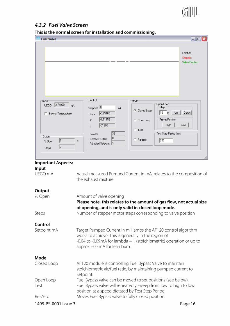
4.3.2 Fuel Valve Screen This is the normal screen for installation and commissioning.
Important Aspects: Input UEGO mA Actual measured Pumped Current in mA, relates to the composition of
the exhaust mixture
Output % Open Amount of valve opening
Please note, this relates to the amount of gas flow, not actual size of opening, and is only valid in closed loop mode.
Steps Number of stepper motor steps corresponding to valve position
Control Setpoint mA Target Pumped Current in milliamps the AF120 control algorithm
works to achieve. This is generally in the region of -0.04 to -0.09mA for lambda = 1 (stoichiometric) operation or up toapprox +0.5mA for lean burn.
Mode Closed Loop AF120 module is controlling Fuel Bypass Valve to maintain
stoichiometric air/fuel ratio, by maintaining pumped current to Setpoint.
Open Loop Fuel Bypass valve can be moved to set positions (see below). Test Fuel Bypass valve will repeatedly sweep from low to high to low
position at a speed dictated by Test Step Period. Re-Zero Moves Fuel Bypass valve to fully closed position.

1495-PS-0001 Issue 3 Page 17
Open Loop These functions only apply in Open Loop Mode. Step The valve moves Up or Down by the percentage amount entered. Eg
entering 10 and clicking Up once will move the valve an additional 10% open.
Preset Position Clicking on High moves the valve to its 90% open position, clicking on Low moves the valve to its 10% open position
Test Step Period This figure is the amount of time between Stepper Motor steps when Test mode is activated. Eg 150ms equates to a sweep of 30 seconds between fully closed and fully open.
4.3.3 IDU-10 Display Unit
An optional display unit is available from Gill Instruments Ltd that allows local monitoring of AF120 operation without use of a PC. The setpoint is also adjustable (under PIN protection). See Appendix 5.

1495-PS-0001 Issue 3 Page 18
5. AF120 Initial Set-Up
To set up and commission the AF120 AFRC system with the standard fuel bypass valve, please follow the process as detailed below. When the procedure mentions a carburettor, this also applies to a mixer or a venturi. See Appendix 6 for notes on use of the 4-20mA output for use with alternative valves.
Stage 1 Ensure AF120 AFRC system is working correctly
1) Ensure Fuel Bypass Valve is connected securely into fuel line.2) Power up AF120 module with the UEGO sensor and Fuel Bypass Valve connected
and check the left hand LED is flashing approximately once per second, and thatthe right hand LED is flashing rapidly.
3) Connect AF120 to PC and run AFPcom software. Select Monitor page.4) Install UEGO sensor into fitting in exhaust5) Close needle valve (if fitted)6) Ensure engine is able to run throughout its normal operating range with air/fuel
ratio set up to approximately stoichiometric (or as required)7) Run engine at idle until it has reached its operating temperature8) Run engine from idle to full load conditions and ensure that UEGO sensor is able
to maintain temperature under all load conditions. Ramp up engine load in 25%load steps and check to see if the UEGO sensor temperature stabilises, using theMonitor page in AFPcom. This can be seen by monitoring on the graph the sensortemperature settling down to a horizontal line, with the Heater Resistancebetween 8.1 – 8.5 Ohms. Check on the Heater page of AFPcom that the requiredheater power is approx 3Watts once the temperature is stable.

1495-PS-0001 Issue 3 Page 19
9) If the UEGO sensor is not able to maintain temperature, move its position. If thesensor is not able to reach temperature (resistance too low, or heater power >3W),move it closer to the engine exhaust manifold; if too hot (resistance too high, orheater power <3W), move it away.
10) Run the engine under normal operating load conditions. Using AFPcom software,on the Monitor page, you should see Input UEGO sensor pump current ofapproximately 0mA for stoich or up to approx 0.5mA for lean burn.
Stage 2 Adjust Control Authority
1) Adjust manual valve (if fitted) to mid position (4 turns from fully closed)2) Using AFPcom software, move Fuel Bypass Valve to mid position by using the
following procedure -
3) With the engine running at normal operating load, use third party emissions testequipment to set air/fuel ratio to the desired value by adjusting the carburettor /venturi mixture screw or equivalent.

1495-PS-0001 Issue 3 Page 20
4) Now test the system’s authority. Using AFPcom software, move the Fuel BypassValve from 10% open to 90% open using the following procedure –
5) If your emission test equipment is able to measure lambda the ideal lambda rangefrom Low position to High position is approximately 0.95 to 1.05 (for stoichoperation with a three way catalyst). The corresponding UEGO pump currentrange is approximately ±0.1mA.a. If lambda range is too high, close needle valve approximately ¼ turn, then go
back to step number 2b. If lambda range is too small, open needle valve approximately ¼ turn, then go
back to step number 2Please Note: Excessive authority might cause the engine to be unstable - the operator should monitor the engine and be prepared to reset the bypass valve to midpoint if problems are detected.

1495-PS-0001 Issue 3 Page 21
Stage 3a Capture Setpoint (for stoich + three way catalyst)
1) Using AFPcom set the Control Setpoint to –0.04mA and press enter (this box willgo red until Enter is pressed).
2) Run engine up to its nominal operating load, wait for engine to reach its normaloperating temperature.
3) Click on Mode > Closed Loop and wait for engine to stabilise.4) Using AFPcom adjust Control Setpoint in small steps while monitoring the Input
UEGO control pumped current output and third party emissions test equipmentuntil emissions are reduced to satisfactory levels This figure is generally in therange of -0.09 to -0.04mA.
5) Run engine from idle to full load in steps on 25% load, and using third partyemissions test equipment, ensure that AF120 system is maintaining stoichiometricconditions.
6) Install catalyst and fine tune set-point with catalyst fitted for optimum emissions(refer to catalyst instructions).
Stage 3b Capture Setpoint (for lean burn operation)
Use the procedure in 3a above, but with a setpoint as required between 0 and approx +0.5mA. If you have access to Advanced mode (see p12), it is possible to configure AF120 touse a MAP sensor to automatically adjust the setpoint as a function of engine load. Contactyour Distributor or Gill Instruments for more information.
Note:- see section 6 for information regarding engine start-up conditions.

1495-PS-0001 Issue 3 Page 22
6. Engine Start-up
The base AF120 configuration provides the following functionality – • On powering the module the AF120 system will close the valve• The valve will stay closed for 60 seconds• After 60 seconds the AF120 will go into closed loop mode and the valve will open• If the valve approaches the top or bottom of its travel within the first 60 seconds of
closed loop mode, the AF120 will not report an error, this is to allow the system tosettle down.
• After 60 seconds of closed loop mode the system will report an error if the valve hitsthe top or bottom of its travel.
If you have advanced access (see page 12) to the AFPcom software you can amend this functionality to change the start-up time and the start-up position. To do this go to the configuration page - the parameters concerned are CloseOnStartPeriod and StartupPos.
To use external control of when AF120 enters closed loop mode, the Enable Input may be used:–
Pin 33 Grounded: Inhibits control – valve moves to start-up position
Pin 33 Open Circuit: Enables closed loop control Closed loop control will not begin until the CloseOnStartPeriod has elapsed AND the enable line is open circuit.
7. Troubleshooting
Power • If the left hand LED on the AF120 is not flashing when the power to the module is
turned on, ensure 12-24V power and ground are connected.• Verify with a voltmeter to check power at module, 12 – 24V is required at Pin 1 and Pin
11. If there are still problems please contact Gill Instruments for an applicationengineer’s assistance.
Oxygen Sensor • If the oxygen sensor is not able to reach the stable, controlled operating temperature
after moving sensor around to find optimum position, use the data logging facility inthe AFPcom software to capture 10 – 20 seconds of module operation and email [email protected] with your contact information. An application engineer will contactyou to assist.

1495-PS-0001 Issue 3 Page 23
8. WIRING DIAGRAM (Module Connector Pin-out arrangement)
Note that Pin 1 is located at the bottom right hand side of the Igniter connector (cable entry side). Pins are numbered right to left in each row.
Pin Description Comment 1 Power +ve Permanent Power In (+31V Max) 2 Power –ve Power Ground (0V) 3 Power –ve Power Ground (0V for RS232) 4 5 6 7 8 9 Lambda Sensor (0V) 10 11 12 13 Stepper D 14 Stepper A 15 16 17 18 19 20 21 22 23 RS232 TX For laptop or Gill IDU-10 Display Unit 24 RS232 RX For laptop or Gill IDU-10 Display Unit 25 Stepper C 26 Stepper B 27 Lambda Heater HI 28 Lambda Pump 29 Lambda 30 Lambda Heater LO 31 4-20mA Output For use with a 3rd Party fuel valve. See App 6. 32 Status Line Indicates error condition 33 Enable Line See section 6. 34 35 36

1495-PS-0001 Issue 3 Page 24
Appendix 1 Bosch UEGO Sensor Installation Boss
Threaded Boss for Installation of UEGO sensor into exhaust
All dimensions in mm
Recommended material – Temperature Resistance Stainless Steel e.g SAE 30305

1495-PS-0001 Issue 3 Page 25
Appendix 2 AF120 AFRC System Wiring Diagram

1495-PS-0001 Issue 3 Page 26
Appendix 3 AF120 Module Assembly
(All dimensions in mm except where shown otherwise)

1495-PS-0001 Issue 3 Page 27
Appendix 4 Fuel Bypass Valve Assembly
(All dimensions in mm except where shown otherwise)

1495-PS-0001 Issue 3 Page 28
Appendix 5 IDU-10 Display Unit
An optional display unit is available from Gill Instruments. The display connects to the AF120 via the RS232 serial communications link and allows all the basic operator functionality that is also provided in AFPcom. All operating parameters can be monitored, and there is a PIN-protected facility to adjust the set-point.
The display is available in panel mount and surface mount formats.
Contact your Gill distributor or visit www.gillsc.com for more details.
Appendix 6 Use of 4-20mA Output
A 4-20mA control output is available instead of the stepper drive. This can be activated by using Advanced access to AFPcom (see p12).
The 4-20mA o/p can be used to control a pneumatic actuator driving a turbo wastegate. It can also be used to drive a controllable mixer or venturi.
All features described in this manual are available with both stepper and 4-20mA drive.
Contact your Distributor or Gill Sensors & Controls for more details.