aerial robotics competition: lessons in autonomy … · figure 2: 15-year competition timeline...
TRANSCRIPT
Aerial Robotics Competition: Lessons in Autonomy
Paul Y. Oh∗, Keith W. Sevcik, and William E. GreenDrexel University, Philadelphia, PA, USA 19104
Email: [paul.yu.oh, Keithicus, weg22]@drexel.edu
Abstract
In May 2005, the Indoor Aerial Robot Competition wasinaugurated. The goal of this annual event is to identifybest design practices and gain insight on technical chal-lenges facing the realization of near-Earth unmanned airvehicles. This paper describes the motivation, goals andobjectives of this competition. Over the past two years,undergraduate teams from the Philadelphia-region par-ticipated from schools like Drexel, Swarthmore, BrynMawr, Rowan, Rutgers and Villanova. Robot de-sign, competition highlights and lessons learned are de-scribed in this paper.
IntroductionIn the United States, congress has mandated that one thirdof all £ghter aircraft are to be unmanned by the year 2015(0). This has far reaching and global impacts to both militaryand civilian aviation where both manned and unmanned air-craft will share a common airspace. With less than a decaderemaining, there are still open problems and technical chal-lenges.
One area of particular interest is ¤ying in near-Earth envi-ronments like caves, forests, tunnels and buildings (0). Suchareas are often characterized by poor GPS reception, de-graded communication and varied illumination. As such,executing missions like search-and-rescue and disaster mit-igation are especially time-consuming, laborious and dan-gerous (0) (0). Aerial robots that can ¤y autonomously innear-Earth environments could provide incident comman-ders, £rst responders and medics with situational awarenessand forward area coverage.
Key to realizing near-Earth aerial robots are collisionavoidance sensor suites. The critical gap in the knowledgebase is the absence of performance metrics and technical de-sign requirements. Unclear are sensor parameters like res-olution, dynamic range, bandwidth and signal-to-noise ra-tios that would be necessary for ¤ying in near-Earth environ-ments. Equally important and unde£ned are ¤ight character-istics like turning radius and cruise speed. The net effect is a
∗IEEE Member. Address all correspondence to this author. Thiswork was supported in part by the National Science FoundationCAREER award IIS 0347430Copyright c© 2007, American Association for Arti£cial Intelli-gence (www.aaai.org). All rights reserved.
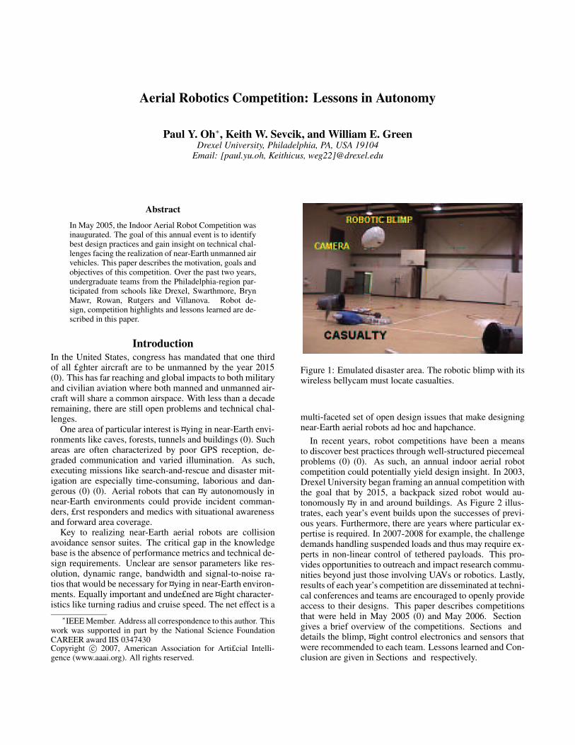
Figure 1: Emulated disaster area. The robotic blimp with itswireless bellycam must locate casualties.
multi-faceted set of open design issues that make designingnear-Earth aerial robots ad hoc and hapchance.
In recent years, robot competitions have been a meansto discover best practices through well-structured piecemealproblems (0) (0). As such, an annual indoor aerial robotcompetition could potentially yield design insight. In 2003,Drexel University began framing an annual competition withthe goal that by 2015, a backpack sized robot would au-tonomously ¤y in and around buildings. As Figure 2 illus-trates, each year’s event builds upon the successes of previ-ous years. Furthermore, there are years where particular ex-pertise is required. In 2007-2008 for example, the challengedemands handling suspended loads and thus may require ex-perts in non-linear control of tethered payloads. This pro-vides opportunities to outreach and impact research commu-nities beyond just those involving UAVs or robotics. Lastly,results of each year’s competition are disseminated at techni-cal conferences and teams are encouraged to openly provideaccess to their designs. This paper describes competitionsthat were held in May 2005 (0) and May 2006. Sectiongives a brief overview of the competitions. Sections anddetails the blimp, ¤ight control electronics and sensors thatwere recommended to each team. Lessons learned and Con-clusion are given in Sections and respectively.
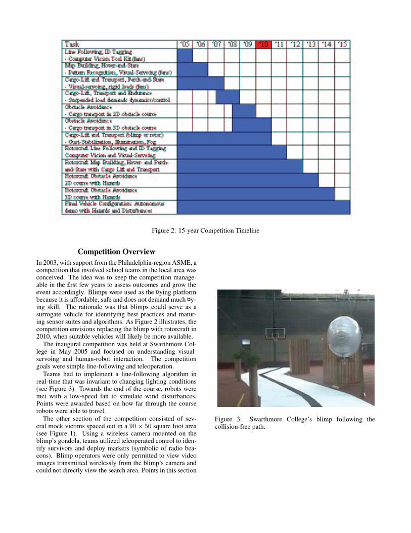
Figure 2: 15-year Competition Timeline
Competition OverviewIn 2003, with support from the Philadelphia-region ASME, acompetition that involved school teams in the local area wasconceived. The idea was to keep the competition manage-able in the £rst few years to assess outcomes and grow theevent accordingly. Blimps were used as the ¤ying platformbecause it is affordable, safe and does not demand much ¤y-ing skill. The rationale was that blimps could serve as asurrogate vehicle for identifying best practices and matur-ing sensor suites and algorithms. As Figure 2 illustrates, thecompetition envisions replacing the blimp with rotorcraft in2010, when suitable vehicles will likely be more available.
The inaugural competition was held at Swarthmore Col-lege in May 2005 and focused on understanding visual-servoing and human-robot interaction. The competitiongoals were simple line-following and teleoperation.
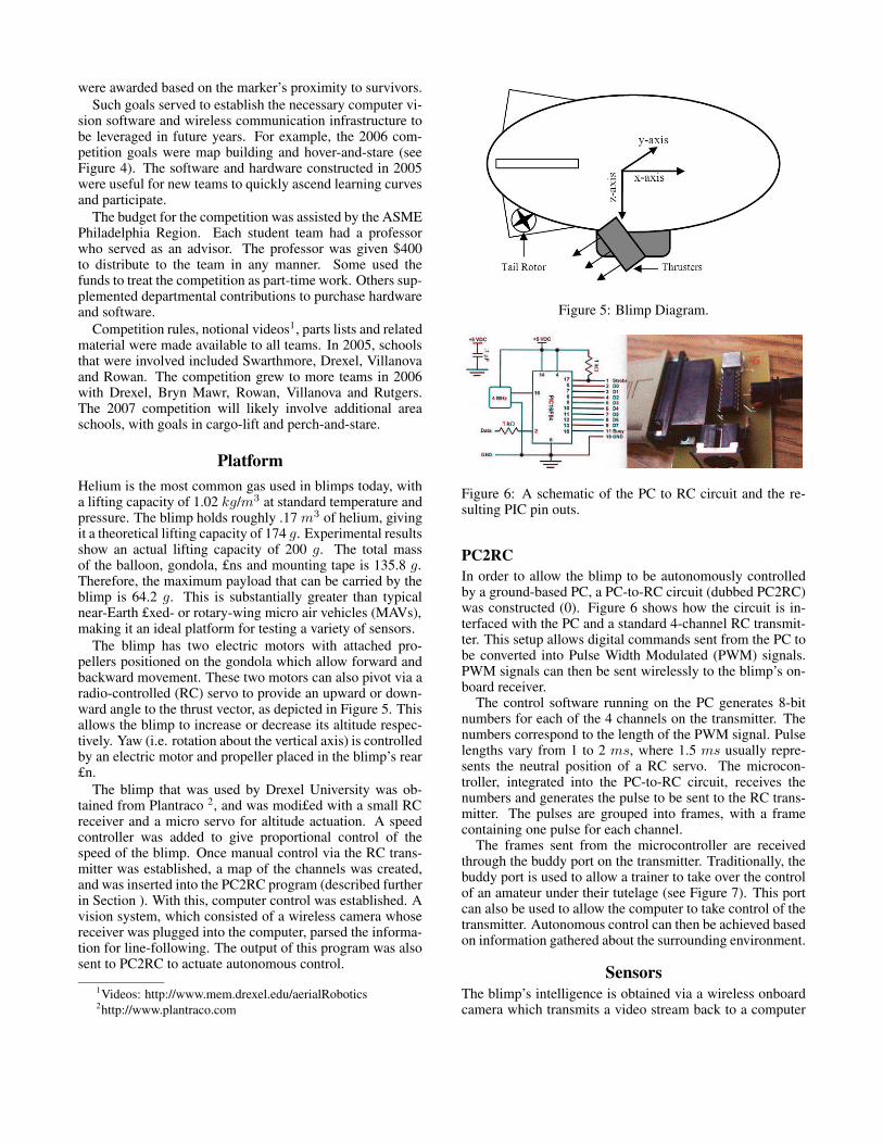
Teams had to implement a line-following algorithm inreal-time that was invariant to changing lighting conditions(see Figure 3). Towards the end of the course, robots weremet with a low-speed fan to simulate wind disturbances.Points were awarded based on how far through the courserobots were able to travel.
The other section of the competition consisted of sev-eral mock victims spaced out in a 90 × 50 square foot area(see Figure 1). Using a wireless camera mounted on theblimp’s gondola, teams utilized teleoperated control to iden-tify survivors and deploy markers (symbolic of radio bea-cons). Blimp operators were only permitted to view videoimages transmitted wirelessly from the blimp’s camera andcould not directly view the search area. Points in this section
Figure 3: Swarthmore College’s blimp following thecollision-free path.
were awarded based on the marker’s proximity to survivors.Such goals served to establish the necessary computer vi-
sion software and wireless communication infrastructure tobe leveraged in future years. For example, the 2006 com-petition goals were map building and hover-and-stare (seeFigure 4). The software and hardware constructed in 2005were useful for new teams to quickly ascend learning curvesand participate.
The budget for the competition was assisted by the ASMEPhiladelphia Region. Each student team had a professorwho served as an advisor. The professor was given $400to distribute to the team in any manner. Some used thefunds to treat the competition as part-time work. Others sup-plemented departmental contributions to purchase hardwareand software.
Competition rules, notional videos1, parts lists and relatedmaterial were made available to all teams. In 2005, schoolsthat were involved included Swarthmore, Drexel, Villanovaand Rowan. The competition grew to more teams in 2006with Drexel, Bryn Mawr, Rowan, Villanova and Rutgers.The 2007 competition will likely involve additional areaschools, with goals in cargo-lift and perch-and-stare.
PlatformHelium is the most common gas used in blimps today, witha lifting capacity of 1.02 kg/m3 at standard temperature andpressure. The blimp holds roughly .17 m3 of helium, givingit a theoretical lifting capacity of 174 g. Experimental resultsshow an actual lifting capacity of 200 g. The total massof the balloon, gondola, £ns and mounting tape is 135.8 g.Therefore, the maximum payload that can be carried by theblimp is 64.2 g. This is substantially greater than typicalnear-Earth £xed- or rotary-wing micro air vehicles (MAVs),making it an ideal platform for testing a variety of sensors.
The blimp has two electric motors with attached pro-pellers positioned on the gondola which allow forward andbackward movement. These two motors can also pivot via aradio-controlled (RC) servo to provide an upward or down-ward angle to the thrust vector, as depicted in Figure 5. Thisallows the blimp to increase or decrease its altitude respec-tively. Yaw (i.e. rotation about the vertical axis) is controlledby an electric motor and propeller placed in the blimp’s rear£n.
The blimp that was used by Drexel University was ob-tained from Plantraco 2, and was modi£ed with a small RCreceiver and a micro servo for altitude actuation. A speedcontroller was added to give proportional control of thespeed of the blimp. Once manual control via the RC trans-mitter was established, a map of the channels was created,and was inserted into the PC2RC program (described furtherin Section ). With this, computer control was established. Avision system, which consisted of a wireless camera whosereceiver was plugged into the computer, parsed the informa-tion for line-following. The output of this program was alsosent to PC2RC to actuate autonomous control.
1Videos: http://www.mem.drexel.edu/aerialRobotics2http://www.plantraco.com
Figure 5: Blimp Diagram.
Figure 6: A schematic of the PC to RC circuit and the re-sulting PIC pin outs.
PC2RCIn order to allow the blimp to be autonomously controlledby a ground-based PC, a PC-to-RC circuit (dubbed PC2RC)was constructed (0). Figure 6 shows how the circuit is in-terfaced with the PC and a standard 4-channel RC transmit-ter. This setup allows digital commands sent from the PC tobe converted into Pulse Width Modulated (PWM) signals.PWM signals can then be sent wirelessly to the blimp’s on-board receiver.
The control software running on the PC generates 8-bitnumbers for each of the 4 channels on the transmitter. Thenumbers correspond to the length of the PWM signal. Pulselengths vary from 1 to 2 ms, where 1.5 ms usually repre-sents the neutral position of a RC servo. The microcon-troller, integrated into the PC-to-RC circuit, receives thenumbers and generates the pulse to be sent to the RC trans-mitter. The pulses are grouped into frames, with a framecontaining one pulse for each channel.
The frames sent from the microcontroller are receivedthrough the buddy port on the transmitter. Traditionally, thebuddy port is used to allow a trainer to take over the controlof an amateur under their tutelage (see Figure 7). This portcan also be used to allow the computer to take control of thetransmitter. Autonomous control can then be achieved basedon information gathered about the surrounding environment.
SensorsThe blimp’s intelligence is obtained via a wireless onboardcamera which transmits a video stream back to a computer
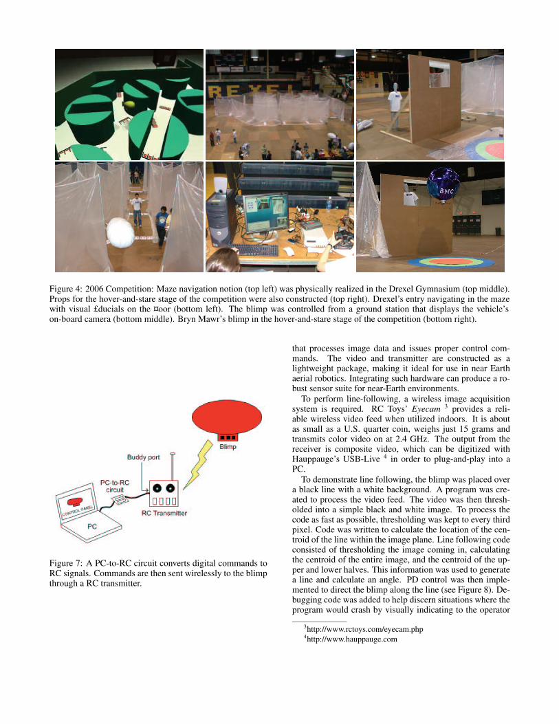
Figure 4: 2006 Competition: Maze navigation notion (top left) was physically realized in the Drexel Gymnasium (top middle).Props for the hover-and-stare stage of the competition were also constructed (top right). Drexel’s entry navigating in the mazewith visual £ducials on the ¤oor (bottom left). The blimp was controlled from a ground station that displays the vehicle’son-board camera (bottom middle). Bryn Mawr’s blimp in the hover-and-stare stage of the competition (bottom right).
Figure 7: A PC-to-RC circuit converts digital commands toRC signals. Commands are then sent wirelessly to the blimpthrough a RC transmitter.
that processes image data and issues proper control com-mands. The video and transmitter are constructed as alightweight package, making it ideal for use in near Earthaerial robotics. Integrating such hardware can produce a ro-bust sensor suite for near-Earth environments.
To perform line-following, a wireless image acquisitionsystem is required. RC Toys’ Eyecam 3 provides a reli-able wireless video feed when utilized indoors. It is aboutas small as a U.S. quarter coin, weighs just 15 grams andtransmits color video on at 2.4 GHz. The output from thereceiver is composite video, which can be digitized withHauppauge’s USB-Live 4 in order to plug-and-play into aPC.
To demonstrate line following, the blimp was placed overa black line with a white background. A program was cre-ated to process the video feed. The video was then thresh-olded into a simple black and white image. To process thecode as fast as possible, thresholding was kept to every thirdpixel. Code was written to calculate the location of the cen-troid of the line within the image plane. Line following codeconsisted of thresholding the image coming in, calculatingthe centroid of the entire image, and the centroid of the up-per and lower halves. This information was used to generatea line and calculate an angle. PD control was then imple-mented to direct the blimp along the line (see Figure 8). De-bugging code was added to help discern situations where theprogram would crash by visually indicating to the operator
3http://www.rctoys.com/eyecam.php4http://www.hauppauge.com
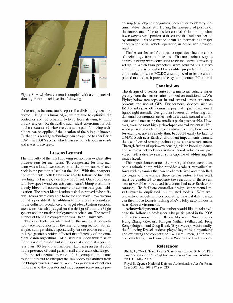
Figure 8: A wireless camera is coupled with a computer vi-sion algorithm to achieve line following.
if the angles became too steep or if a division by zero oc-curred. Using this knowledge, we are able to optimize thecontroller and the program to keep from straying to theseunruly angles. Realistically, such ideal environments willnot be encountered. However, the same path following tech-niques can be applied if the location of the blimp is known.Further, this sensing technology can be applied to near EarthUAV’s with GPS access which can use objects such as roadsand rivers to navigate.
Lessons LearnedThe dif£culty of the line following section was evident afterpractice runs for each team. To compensate for this, eachteam was allotted two restarts (i.e. the blimp can be placedback in the position it last lost the line). With the incorpora-tion of this rule, both teams were able to follow the line untilreaching the fan area, a distance of 75 feet. Once confrontedwith low speed wind currents, each team’s blimp was imme-diately blown off course, unable to demonstrate gust stabi-lization. The target identi£cation task also proved to be dif£-cult. Teams were only able to locate and mark 1 to 4 victimsout of a possible 8. In addition to the scores accumulatedin the collision avoidance and target identi£cation sections,each team was also judged on the design of both the ¤ightsystem and the marker deployment mechanism. The overallwinner of the 2005 competition was Drexel University.
The key challenges identi£ed in the inaugural competi-tion were found mostly in the line following section. For ex-ample, sunlight shined sporadically on the course resultingin large gradients which effected the ef£ciency of the com-puter vision algorithms. Also, wireless video transmissionindoors is diminished, but still usable at short distances (i.e.less than 100 feet). Furthermore, stabilizing an aerial robotin the presence of wind gusts is still a prevalent challenge.
In the teleoperated portion of the competition, teamsfound it dif£cult to interpret the raw video transmitted fromthe blimp’s wireless camera. A bird’s eye view is oftentimesunfamiliar to the operator and may require some image pro-
cessing (e.g. object recognition) techniques to identify vic-tims, tables, chairs, etc. During the teleoperated portion ofthe course, one of the teams lost control of their blimp whenit was ¤own over a portion of the course that had been heatedby sunlight. This observation identi£ed thermals as a majorconcern for aerial robots operating in near-Earth environ-ments.
The lessons learned from past competitions include a mixof technology from both teams. The most robust way tocontrol a blimp were concluded to be the Drexel Universityset up, in which twin propellers were actuated via a servoand turning was propelled by a rudder propeller. For radiocommunications, the PC2RC circuit proved to be the cham-pioned method, as it provided easy to implement PC control.
ConclusionsThe design of a sensor suite for a micro air vehicle variesgreatly from the sensor suites utilized on traditional UAVs.Flying below tree tops or in and around urban structuresprevents the use of GPS. Furthermore, devices such asIMU’s and gyros often strain the payload capacities of small,lightweight aircraft. Design then focuses on achieving fun-damental autonomous tasks such as altitude control and ob-stacle avoidance using the smallest packages possible. How-ever, even the most highly-developed control system will failwhen presented with unforeseen obstacles. Telephone wires,for example, are extremely thin, but could easily be fatal toa MAV. Such near-Earth environment impediments demandthe use of varied sensing technologies to ensure robustness.Through fusion of optic ¤ow sensing, vision based guidanceand wireless network localization, aerial vehicles are pro-vided with a diverse sensor suite capable of addressing theissues faced.
This paper demonstrates the porting of these techniquesonto a robotic blimp, which provides a robust, versatile plat-form with dynamics that can be characterized and modelled.To begin to characterize these sensor suites, future workmust be conducted to measure the reactions of these sen-sors to variables introduced in a controlled near-Earth envi-ronment. To facilitate controller design, experimental re-sults must be duplicated in simulated models. With wellunderstood models and corroborating physical data, designcan then move towards making MAV’s fully autonomous innear-Earth environments.
Acknowledgements: The author would like to acknowl-edge the following professors who participated in the 2005and 2006 competitions: Bruce Maxwell (Swarthmore),Hong Zhang (Rowan), Rungan Nathan (Villanova), PengSong (Rutgers) and Doug Blank (Bryn Mawr). Additionally,the following Drexel students played key roles in organizingand executing the competition: William Green, Keith Sev-cik, Vefa Narli, Dan Hanna, Steve Wilrigs and Paul Gisondi.
ReferencesBlitch, J., “World Trade Center Search-and-Rescue Robots”, Ple-nary Session IEEE Int Conf Robotics and Automation, Washing-ton D.C., May 2002.Floyd D. Spence National Defense Authorization Act for FiscalYear 2001, P.L. 106-398 Sec 220.
Green, W.E., Sevcik, K.W., Oh, P.Y., “A Competition to IdentifyKey Challenges for Unmanned Aerial Robots in Near-Earth Envi-ronments”, IEEE International Conference on Advanced Robotics(ICAR), Seattle, WA, pp. 309-315, July 2005.
Kitano, H.; Asada, M.; Noda, I.; Matsubara, H., “RoboCup: robotworld cup”, IEEE Robotics and Automation Magazine, V5, N3,pp. 30-36, September 1998.
Murphy, R., et al, “Mobility and sensing demands in USAR”,IEEE Industrial Electronics Conference (IECON), V1, pp. 138-142, 2000.
Murray, R.M., “Autonomous Machines: Racing to Win theDARPA Grand Challenge”, Proc. American Control Conf., Port-land, OR, pp. 9-10, June 2005.
Oh, P.Y., Green, W.E., “Closed Quarter Aerial Robot Prototypeto Fly In and Around Buildings”, Int. Conference on Computer,Communication and Control Technologies, Orlando, FL, pp. 302-307, July
Sevcik, K., Oh, P. “PC to RC Interface”, Servo Magazine, July2004