aemc instruments 2015 export catalog
DESCRIPTION
Electrical Testing & Measurement Equipment, megohmmeters, data loggers, ground testers, power, energy, micro-ohmmeters, current, voltage, multimeters, oscilloscopes, electrical test equipment, clamp meters, current probesTRANSCRIPT

TEST & MEASUREMENT INSTRUMENTS
Technical Hotline: (800) 343-1391www.aemc.com
ww
w.aem
c.com
2015
AEMC
® INSTR
UM
ENTS
2015 TE
ST
& M
EA
SU
RE
ME
NT
CA
TAL
OG
Cable Testers
Clamp-On Meters
Current Measurement Probes
Data Loggers
DC Power Supplies
Decade Boxes
Digital Multimeters
Electrical Test Tools
Environmental Testers
Ground Resistance Testers
High Voltage Testers
Leakage Current Meters and Probes
Megohmmeters
Micro-Ohmmeters
Oscilloscopes
Power Quality Analyzers, Meters and Energy Loggers
Transformer Ratiometers
Other Products from the Chauvin Arnoux Group
Our pr
oduc
ts ar
e bac
ked
by o
ver 1
00 y
ears
of e
xper
ienc
e in
test
and
mea
sure
men
t equ
ipm
ent,
and
enco
mpa
ss th
e la
test
inte
rnat
iona
l sta
ndar
ds fo
r qua
lity an
d safe
ty.

HOW TO ORDER
Chauvin Arnoux®, Inc. d.b.a. AEMC® InstrumentsChauvin Arnoux One Source® AEMC
Find us on the WEB at WWW.
.COMDetailed product brochures available on the web!
All AEMC® Instruments products are available through a network of authorized electrical, electronic and instrumentation distributors.
If you have difficulty locating a North American distributor near you, contact AEMC® Instruments or your local AEMC® Instruments sales representative or check www.aemc.com for a distributor in your area by clicking on the "Where to Order" tab:
AEMC® Instruments 200 Foxborough Blvd. Foxborough, MA 02035 USA (508) 698-2115 • Fax (508) 698-2118 Technical Hotline: (800) 343-1391 [email protected] • www.aemc.com
For Ordering Information (within North America): Chauvin Arnoux®, Inc., d.b.a. AEMC® Instruments 15 Faraday Drive Dover, NH 03820 USA (800) 442-2362 • Fax (603) 749-9153 [email protected]
Export Department (all other countries than U.S.A & Canada): Tel +1 (603) 749-6434 ext. 520 Fax +1 (603) 740-7550 [email protected]
When ordering, please use the catalog number and product description.
Example:
Quantity Catalog # Description
1 2141.02 Ground Resistance Tester Model 6417 (Clamp-On) with memory and alarm
A separate price list is available. Contact your AEMC® Instruments distributor or AEMC®
Instruments for an up-to-date copy.
AEMC® Instruments reserves the right to discontinue models at any time, or change specifications, price or design without notice and without incurring any obligation. Please contact us, your local representative, agent or distributor for updates.
950.CAT-MASTER-EXPORT-2015 Digital copy only Rev.00 06/15

CONT
ENTS Megohmmeters 2
Power Quality Analyzers, Meters & Loggers 14
Ground Resistance Testers 27
Cable Testers 40
Data Loggers 43
Environmental Testers 58
Clamp-On Meters 63
Leakage Current Meters and Probes 69
Digital Multimeters 72
Handheld Oscilloscopes 73
Current Measurement Probes 76
DC Power Supplies & Decade Boxes 85
Electrical Test Tools 86
High Voltage Detectors 88
Micro-Ohmmeters 89
Transformer Ratiometers 92
Other Products from Chauvin Arnoux® Group 94
Catalog Cross Reference Index 102
Training Seminars 104
2 www.aemc.com Technical Assistance (800) 343-1391
Learn how to measure insulation on
telephone cables
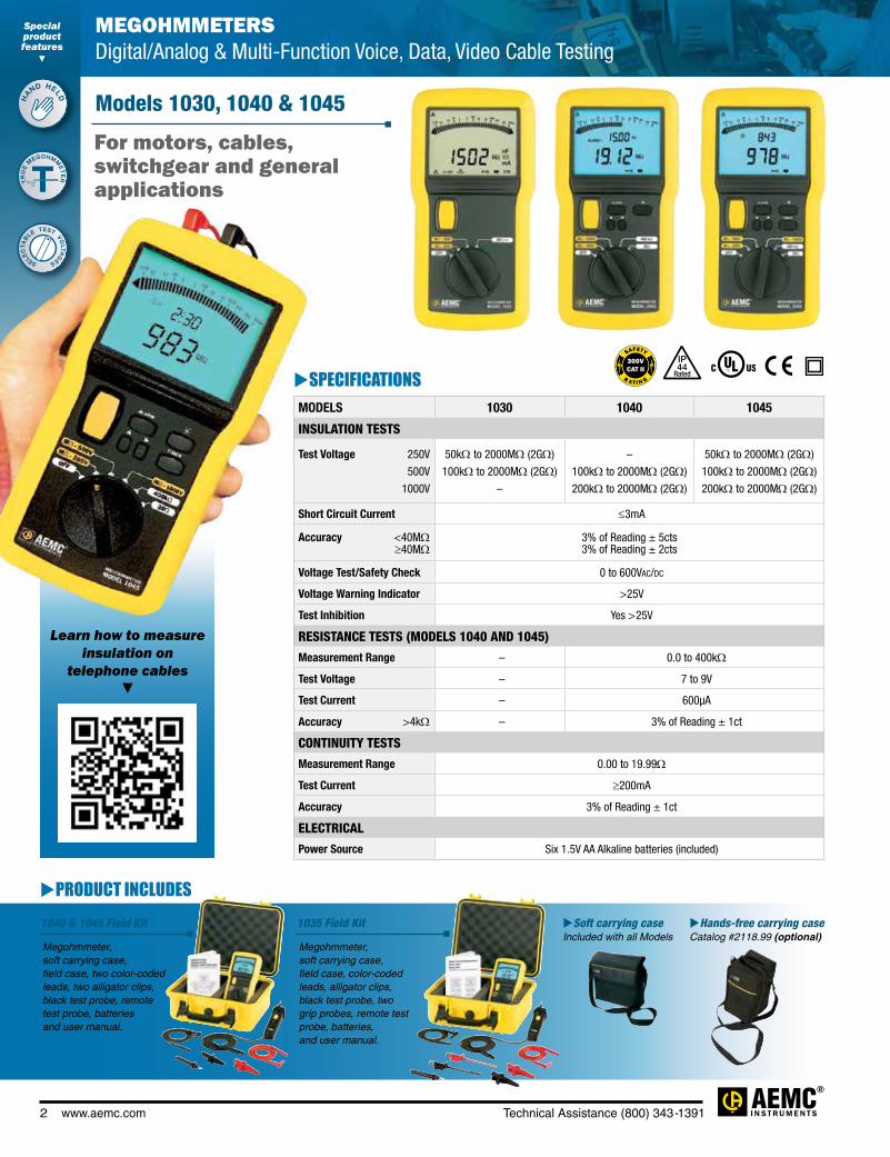
MEGOHMMETERS Digital/Analog & Multi-Function Voice, Data, Video Cable Testing
Models 1030, 1040 & 1045
SPECIFICATIONSMODELS 1030 1040 1045
INSULATION TESTS
Test Voltage 250V
500V
1000V
50kΩ to 2000MΩ (2GΩ)
100kΩ to 2000MΩ (2GΩ)
–
–
100kΩ to 2000MΩ (2GΩ)
200kΩ to 2000MΩ (2GΩ)
50kΩ to 2000MΩ (2GΩ)
100kΩ to 2000MΩ (2GΩ)
200kΩ to 2000MΩ (2GΩ)
Short Circuit Current ≤3mA
Accuracy <40MΩ ≥40MΩ
3% of Reading ± 5cts 3% of Reading ± 2cts
Voltage Test/Safety Check 0 to 600Vac/dc
Voltage Warning Indicator >25V
Test Inhibition Yes >25V
RESISTANCE TESTS (MODELS 1040 AND 1045)
Measurement Range – 0.0 to 400kΩ
Test Voltage – 7 to 9V
Test Current – 600µA
Accuracy >4kΩ – 3% of Reading ± 1ct
CONTINUITY TESTS
Measurement Range 0.00 to 19.99Ω
Test Current ≥200mA
Accuracy 3% of Reading ± 1ct
ELECTRICAL
Power Source Six 1.5V AA Alkaline batteries (included)
For motors, cables, switchgear and general applications
PRODUCT INCLUDES
Megohmmeter, soft carrying case, field case, two color-coded leads, two alligator clips, black test probe, remote test probe, batteries and user manual.
Megohmmeter, soft carrying case, field case, color-coded leads, alligator clips, black test probe, two grip probes, remote test probe, batteries, and user manual.
1040 & 1045 Field Kit 1035 Field Kit Soft carrying case Included with all Models
Hands-free carrying case Catalog #2118.99 (optional)
Special product features
HAND HELD
TRU
E M
EGOHMME
TE
R
SELEC
TAB
LE TEST VOLTA
G
ES
T
IP
Rated44

Technical Assistance (800) 343-1391 www.aemc.com 3
SPECIFICATIONSMODELS 1035 1039INSULATION TESTSTest Voltage 50V 100V 250V 500V
10kΩ to 2000MΩ (2GΩ)20kΩ to 2000MΩ (2GΩ)
50kΩ to 20,000MΩ (20GΩ)100kΩ to 20,000MΩ (20GΩ)
10kΩ to 400MΩ20kΩ to 400MΩ
––
Open Circuit Voltage <75V @ 50V, <150V @ 100V, <375V @ 250V, <750V @ 500VShort Circuit Current ≤3mAAccuracy ±3% of Reading ± 5ctsVoltage Test/Safety Check 0 to 600Vac/dc
Voltage Warning Indicator >25VTest Inhibition Yes >25VRESISTANCE TESTSMeasurement Range 0.0 to 400kΩ 0.0 to 40.0kΩTest Voltage 7 to 9V 7 to 9VTest Current 600µA < 400Ω; 6µA > 40Ω 600µA < 400ΩAccuracy >400kΩ ±3% of Reading ± 1ct ±3% of Reading ± 1ctCURRENT TESTSAC/DC Current Range
– 0.00 to 400mA (240A) (with probe option)
CAPACITANCE/CABLE LENGTHCapacitance Range – 0.00 to 4000nFCable Length Range – 0.000 to 80.0kmVOLTAGE TESTSMeasurement Range – 0 to 400Vac
Accuracy – ±3% of Reading ± 1ctELECTRICALPower Source Six 1.5V AA Alkaline batteries (included)
CATALOG NO. DESCRIPTION
2116.89 Megohmmeter Model 1030 (Digital w/Analog Bargraph, 250V, 500V, soft carrying bag, batteries, leads, alligator clips)
2116.92Megohmmeter Model 1040 (Digital w/Analog Bargraph, Alarm, Backlight, 500V, 1000V, 400kΩ, Continuity, soft carrying bag, batteries, leads, alligator clips)
2116.93Megohmmeter Model 1045 (Digital w/Analog Bargraph, Alarm, Timer, Backlight, 250V, 500V, 1000V, 400kΩ, Continuity, soft carrying bag, batteries, leads, alligator clips)
2117.30 Megohmmeter Model 1040 Field Kit (Model 1040, Remote Test Probe & Field Case)2117.31 Megohmmeter Model 1045 Field Kit (Model 1045, Remote Test Probe & Field Case)2116.90 Megohmmeter Model 1035 (Digital w/Analog Bargraph, Alarm, Backlight, 50V, 100V, 250V, 500V, 400kΩ)2116.91 Megohmmeter Model 1039 (Digital w/Analog Bargraph, Alarm, Timer, ∆Rel, Backlight, 50V, 100V, mA, nF, km)2115.42 Megohmmeter Model 1035 Field Kit (Model 1035, Remote Test Probe & Field Case)Accessories (Optional)2118.97 Remote Test Probe2118.98 Field Case (Waterproof)2118.99 Hands-Free Carrying Case
Models 1035 & 1039
FEATURES• True Megohmmeter®
• Test voltage combinations of 250V, 500V and 1000V
• Insulation measurements to 2000MΩ (2GΩ)• Automatic test inhibition
(if live sample >25V)• Automatic discharge for operator safety• Multi-line, 4000-count, backlit, digital
display with analog bargraph• Resistance measurements to 400kΩ• Continuity with 200mA test current• Timer function for easy DAR and PI
(Model 1045)• Slip-proof, over-molded, protective rubber
housing for rugged field use• Includes test leads and soft carrying case• Test voltage combinations of 50V, 100V,
250V and 500V (Model 1035)• Insulation measurement to 20,000MΩ
(20GΩ) (Model 1035)• Insulation measurement to 400MΩ
(Model 1039)• Capacitance measurement to 4000nF
(Model 1039)• Cable length measurement to 80.0km
(>264,000 ft) (Model 1039)• Ideal for telecom testing and high
sensitivity measurements• Backlit display (Models 1035, 1039, 1040 & 1045)
For voice, data and video cable applications
IP
Rated44

MEGOHMMETERS 5000V Digital
4 www.aemc.com Technical Assistance (800) 343-1391
Model 6527
Specially designed for testing installations and equipment
MEGOHMMETERS 1000V Digital
PRODUCT INCLUDES
Soft carrying case, set of two 5 ft color-coded test leads, alligator clips, one black test probe and user manual.
FEATURES• True Megohmmeter®
• Insulation test voltage selections of 250V, 500V and 1000V
• Measure insulation to 4000MΩ (4GΩ)
• TEST LOCK feature for time sensitive measurements up to 15 minutes
• Auto discharge after insulation test
• AC/DC voltmeter to 600Vac/1000Vdc
• Ohmmeter to 400kΩ• Continuity meter up to 200mA
test current
• Test lead resistance compensation for accurate low resistance measurements
• Auto HOLD function to “freeze” readings
• Large and bright dual display with blue backlight
• Auto Power OFF feature
• Ergonomic over-molded case with back-stand
• Complies with International Insulation Testing Standards including EN61557
SPECIFICATIONSMODEL 6527
INSULATION TESTSTest Voltage 250V 500V 1000V
1kΩ to 4000MΩ (4GΩ) 1kΩ to 4000MΩ (4GΩ) 1kΩ to 4000MΩ (4GΩ)
Accuracy 4MΩ/40MΩ 400MΩ 4000MΩ (4GΩ)
2% of Reading ± 10cts 3% of Reading ± 5cts 4% of Reading ± 5cts
VOLTMETERV AC/DC 600V/1000V
Accuracy DC AC
0.8% of Reading ± 3cts 1.2% of Reading ± 10cts
RESISTANCE TESTS - OHMMETERRange 0.0 to 400.0kΩ
Accuracy 1.2% of Reading ± 3cts
CONTINUITY TESTSRange 0.00 to 400Ω
Accuracy 1.2% of Reading ± 3cts
Test Current >200mA (0.2Ω/2Ω)
Test Lead Compensation Yes – dedicated push-button
Beeper Yes – <35Ω ± 3Ω
ELECTRICALPower Supply Six 1.5V AA batteries – Alkaline recommended (included)
CATALOG NO. DESCRIPTION
2126.53 Megohmmeter Model 6527 (Digital, 250V, 500V, 1000V, Continuity, 400kΩ, V)
Special product features
''' '''''
ME
GO
HMMETER/ D
MM
CONDUCT
BA
C
KLIT DISPLAY
C O M B O
SP
OT & T I M E D T
ES
TS
ΩD
IP
Rated51

MEGOHMMETERS 5000V Digital
Technical Assistance (800) 343-1391 www.aemc.com 5
Test insulation on cables, transformers, motors and wiring
installations
Models 1050 & 1060
FEATURES• True Megohmmeter ®
• Test voltage selections of 50V, 100V, 250V, 500V and 1000V• Insulation measurements to 4000GΩ (4TΩ)• Direct measurement of DAR and PI values• Direct measurement of sample capacitance• Display of test voltage and run time• Programmable test run times and PI times• Smooth and Alarm functions• Automatic test inhibition (if live sample >25V)• Automatic discharge and display of discharge voltage• Large dual display with time, voltage and measurement• Bright blue electroluminescent backlight• Battery powered (Model 1050)• Auto Power OFF when not in use• Remote operation with optional test probe• Rugged, dual wall, weatherproof field case with detachable lead/accessory pouch• EN 61010-1, 600V CAT III, EN 61557
Model 1060 includes the following additional features:• AC rechargeable NiMH battery pack• RS-232 interface with USB 2.0 cable for DataView® easy report printing• 128kB memory to store measurements in specific files• Remote operation of megohmmeter through PC• Includes DataView® software for data storage, real-time display, analysis and report generation
CATALOG NO. DESCRIPTION
2130.01 Megohmmeter Model 1050 (Digital, with Analog Bargraph, Backlight, Alarm, Timer, 50V, 100V, 250V, 500V, 1000V, Auto DAR/PI, Resistance, Continuity)
2130.03 Megohmmeter Model 1060 (Digital, with Analog Bargraph, Backlight, Alarm, Timer, 50V, 100V, 250V, 500V, 1000V, Auto DAR/PI, Resistance, Continuity, USB Sitck w/DataView® software, 128kB Memory)
2118.97 Remote Test Probe
SPECIFICATIONSMODELS 1050 1060
INSULATION TESTSTest Voltage 50V 100V 250V 500V 1000V
2kΩ to 200GΩ 4kΩ to 400GΩ
10kΩ to 1000GΩ (1TΩ) 20kΩ to 2000GΩ (2TΩ) 40kΩ to 4000GΩ (4TΩ)
Accuracy 2kΩ to 40GΩ 40GΩ to 4TΩ
5% of Reading ± 3cts 15% of Reading ± 10cts
Voltage Test/Safety Check 0 to 1000Vac/dc
Voltage Warning Indicator >25VTest Inhibition Yes >25VSmooth Function Yes
RESISTANCE TESTSMeasurement Range 0.01Ω to 400kΩTest Voltage 12.4Vdc maxTest Current <6mAdc
Accuracy >4kΩ ±3% of Reading ± 3cts
CONTINUITY TESTSMeasurement Range 0.01 to 39.99ΩTest Current ≥200mA from 0.01 to 20.00ΩAccuracy ±3% of Reading ± 4cts
COMMUNICATIONMemory of Reading over Time R(t) Yes (20 Readings) Yes
(128kB memory)Memory of Test Results in Files
No128kB memory
with RS-232 to USB adapter (included)
PC Software/Report Generation No DataView®
(included)
ELECTRICALPower Source Eight 1.5V C Cells
(included)
9.6V NiMH Battery Pack (included) 85 to
256V (50/60Hz)
PRODUCT INCLUDES
One red, one blue test lead, one black shielded lead, one each black, red and blue alligator clips,
one black test probe and user manual. Model 1060 also includes RS-232 to USB adapter, DB9 F/F 6 ft null modem cable, rechargeable battery, US 120V
power cord, and USB stick supplied with DataView® software and user manual.
Special product features
US
ER
P
ROGRAM
MA
BL
E
DAT
A STORAGE
SELEC
TAB
LE TEST VOLTA
G
ES
MEGOHMMETERS 1000V Digital/Analog
IP
Rated54

6 www.aemc.com Technical Assistance (800) 343-1391
SPECIFICATIONSMODEL 6505INSULATION TESTSTest Voltage/Range
500V1000V2500V5000V
30kΩ to 2000GΩ (2TΩ) 100kΩ to 4000GΩ (4TΩ) 100kΩ to 10,000GΩ (10TΩ) 300kΩ to 10,000GΩ (10TΩ)
User Programmable Test 40 to 1000V: 10V increments1000 to 5100V: 100V increments
Short Circuit Current <1.6mA ± 5%Accuracy 10kΩ to 40GΩ
40GΩ to 10TΩ±5% of Reading ± 3cts
±15% of Reading ± 10ctsDAR (1 min/30 sec) 0.02 to 50.00PI (10 min/1 min & user programmable) 0.02 to 50.00
Capacitance Measurement 0.005 to 49.99µF; Max resolution 1nF
Leakage Current Measurement
0.00nA to 3mA; Max resolution 1pA
Programmable Run Time R(t) 1 to 60 minutesDischarge After Test Yes, automaticDischarge Voltage Display YesVoltage Test/Safety Check 2500Vac/4000Vdc (16 to 420Hz);
1V ResolutionVoltage Warning Indicator Yes >25VTest Inhibition* Yes >25VGuard Terminal Yes
ELECTRICALPower Source One 9.6V NiMH battery pack (included);
Line power: 85 to 256Vac (50/60Hz)
*Inhibit voltage is selectable at 3, 10 or 20% of test voltage
CATALOG NO. DESCRIPTION
2130.18Megohmmeter Model 6505 (Digital, with Analog Bargraph, Backlight, 500V, 1000V, 2500V, 5000V, Auto DAR/PI)
Accessories (Optional)
2119.76Lead – Set of 3, Color-coded 10ft 5kV Safety w/3 Color-coded Alligator Clips (1000V CAT IV) 15A for use with Megohmmeter Models 5050/5060/5070/6505
2119.77 Lead – Replacement, Set of 3, Color-coded 6ft 5kV safety for Megohmmeter Model 6505
2119.85 Lead – Set of 3, Color-coded 10ft 5kV Safety with Integral Hippo Clips, and jumper lead for use with Megohmmeter Model 6505 (replacement for 5050/5060/5070)
2119.86 Lead – Set of 3, Color-coded 25ft 5kV Safety with Integral Hippo Clips for use with Megohmmeter Models 5050/5060/5070/6505 [Jumper lead not included]
2119.87 Lead – Set of 3, Color-coded 45ft 5kV Safety with Integral Hippo Clips for use with Megohmmeter Models 5050/5060/5070/6505 [Jumper lead not included]
MEGOHMMETERS 5000V Digital/Analog
Model 6505
Contributes to the safety of electrical installations and equipment
PRODUCT INCLUDES
Extra large classic tool bag, three color-coded leads, one blue jumper lead for use with guard terminal, three alligator clips (600V CAT IV), US 115V power cord, rechargeable battery pack and user manual.
FEATURES• True Megohmmeter®
• Simple operation• Test voltage selections of 500V, 1000V, 2500V and 5000V • Insulation measurements from 30kΩ to 10TΩ (10,000GΩ) • Adjustable and programmable test voltage
(40 to 5100V) • Automatic calculation of DAR and
PI values • Direct measurement and display of Capacitance and Leakage Current • Display resistance, test voltage
and run time • Programmable test run times and PI ratio times • Automatic test inhibition
(if live sample >25V) • Automatic discharge and display of discharge voltage • Large backlight LCD dual-display
with time, voltage and measurements shown
• Rugged, dual wall, weatherproof field case • Designed and built to IEC safety standards • EN 61010-1, 1000V CAT III
Special product features
HIG
H R
ES
ISTA
NCE MEASUR
EM
ENTS
AUTOM
AT
IC
RATIO CALC
UL
AT
IO
NS
SELEC
TAB
LE TEST VOLTA
G
ES
Φ
IP
Rated53

Technical Assistance (800) 343-1391 www.aemc.com 7
R AT I N G
SAFETY
Special product features
HIG
H R
ES
ISTA
NCE MEASUR
EM
ENTS
AUTOM
AT
IC
RATIO CALC
UL
AT
IO
NS
SELEC
TAB
LE TEST VOLTA
G
ES
Φ
See page 11 for details
MEGOHMMETERS 5000V Digital/Analog
Designed with the highest level of safety features built in
Models 5050 & 5060
Print measurement
reports directly from your computer using DataView® software
(Models 5060 & 5070)
PRODUCT INCLUDESPC RS-232 Cable Catalog #2119.45 DB9 F/F 6 ft null modem cable Catalog #5000.60 RS-232 to USB adapter
USB Stick Supplied with DataView® software and user manual (Models 5060 & 5070)
5050, 5060 & 5070
Extra large classic tool bag, one red, one blue and one black lead
with integral 5kV rated hippo clips, one jumper lead for use
with guard terminal, 120V power cord, rechargeable battery and
user manual.
IP
Rated53
SPECIFICATIONSMODELS 5050 5060
INSULATION TESTSTest Voltage 500V 1000V 2500V 5000V
30kΩ to 2000GΩ (2TΩ) 100kΩ to 4000GΩ (4TΩ)
100kΩ to 10,000GΩ (10TΩ) 300kΩ to 10,000GΩ (10TΩ)
User Selectable Test Voltage Programmable: 40 to 1000V: 10V increments;
1000 to 5100V: 100V incrementsAutomatic Step Voltage –Accuracy 1kΩ to 40GΩ 40GΩ to 10TΩ
±5% of Reading ± 3cts ±15% of Reading ± 10cts
Voltage Test/Safety Check 2500Vac/4000Vdc
Voltage Warning Indicator Yes >25V
Test Inhibition* Yes — adjustable from 25 to 1000V depending on test voltage range in use
Smooth Function (user selectable) Digital filtering stabilizes display readings
COMMUNICATIONStorage of Readings over Time R(t) 4kB memory 128kB memory
Storage of Test Results 20 Readings Stores over 1500 test resultsCommunication Port – Serial and RS-232 to USB adapter (included) PC Software/Report Generation No DataView® (included)
ELECTRICALPower Source One 9.6V NiMH battery pack (included)
Line power: 85 to 256V (50/60Hz)*Inhibit voltage is selectable at 3, 10 or 20% of test voltage
CATALOG NO. DESCRIPTION
2130.20 Megohmmeter Model 5050 (Digital, with Analog Bargraph, Backlight, Alarm, Timer, 500V, 1000V, 2500V, 5000V, Auto DAR/PI/DD)
2130.21 Megohmmeter Model 5060 (Digital, with Analog Bargraph, Backlight, Alarm, Timer, 500V, 1000V, 2500V, 5000V Auto DAR/PI/DD, USB Stick w/DataView® software)

8 www.aemc.com Technical Assistance (800) 343-1391
SPECIFICATIONSMODEL 5070INSULATION TESTSTest Voltage 500V 1000V 2500V 5000V
30kΩ to 2000GΩ (2TΩ) 100kΩ to 4000GΩ (4TΩ)
100kΩ to 10,000GΩ (10TΩ) 300kΩ to 10,000GΩ (10TΩ)
User Selectable Test Voltage
Programmable: 40 to 1000V: 10V increments; 1000 to 5100V: 100V increments
Automatic Step Voltage Programmable step voltage and duration up to five steps. Three profiles can be stored.
Accuracy 1kΩ to 40GΩ 40GΩ to 10TΩ
±5% of Reading ± 3cts ±15% of Reading ± 10cts
Voltage Test/Safety Check 2500Vac/4000Vdc
Voltage Warning Indicator Yes >25V
Test Inhibition* Yes — adjustable from 25 to 1000V depending on test voltage range in use
Smooth Function (user selectable) Digital filtering stabilizes display readings
COMMUNICATIONStorage of Readings over Time R(t) 128kB memory
Storage of Test Results Stores over 1500 test resultsCommunication Port Serial and RS-232 to USB adapter (included)
PC Software/ Report Generation DataView® (included)
ELECTRICALPower Source One 9.6V NiMH battery pack (included)
Line power: 85 to 256V (50/60Hz)*Inhibit voltage is selectable at 3, 10 or 20% of test voltage
CATALOG NO. DESCRIPTION
2130.30 Megohmmeter Model 5070 (Graphical, Analog Bargraph, Backlight, Alarm, Timer, 500V, 1000V, 2500V, 5000V, Ramp, Auto DAR/PI/DD, USB Stick w/DataView® software)
Accessories (See page 7 for optional accessories)2119.45 Cable, PC RS-232, DB9 F/F 6 ft Null Modem Cable (for use with Models 1060, 5060 & 5070)
Insulation resistance measurement graphically displayed at the completion of the test at the push of a button.
MEGOHMMETERS 5000V Graphical
Model 5070
Offers real-time graphic plot of measurements and digital presentation of test results
Special product features
GRAPHIC
PLO
T OF MEASUR
EM
ENTS
PROGRA
MM
ABLE STEP VO
LTAG
E TEST
AUTOM
ATI
C RATIO CALCU
LAT
IONS
Φ
FEATURES• True Megohmmeter ®
• Test voltage selections of 500V, 1000V, 2500V and 5000V• Insulation measurements from 30kΩ to 10,000GΩ (10TΩ)• Selectable and programmable test voltage (40 to 5100V)• Automatic calculation of DAR, PI and DD ratios• Direct measurement and display of Capacitance and Leakage Current• Display resistance, test voltage and run time• Programmable test run times and PI ratio times• Smooth and Alarm functions• Automatic test inhibition (if live sample >25V)• Automatic discharge and display of discharge voltage• Graphic and digital display of test voltage, resistance and more• Bright blue electroluminescent backlight• Programmable temperature compensation• Programmable test voltage lock-out• Programmable alarm setting• Auto Power OFF when not in use• AC or DC powered with rechargeable NiMH battery pack - run while charging• Rugged, weatherproof field case• Designed and built to IEC safety standards• Includes DataView® software for data storage, real-time display, analysis and report generation (Models 5060 & 5070)• EN 61010-1, 1000V CAT III
R AT I N G
SAFETY
IP
Rated53
Technical Assistance (800) 343-1391 www.aemc.com 9
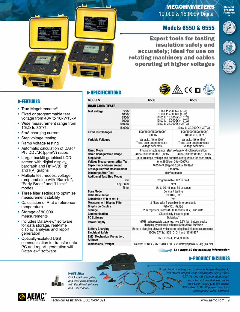
SPECIFICATIONSMODELS 6550 6555
INSULATION TESTSTest Voltage 500V 1000V 2500V 5000V
10,000V
10kΩ to 2000GΩ (2TΩ) 10kΩ to 4000GΩ (4TΩ)
10kΩ to 10,000GΩ (10TΩ) 10kΩ to 15,000GΩ (15TΩ) 10kΩ to 25,000GΩ (25TΩ)
15,000V – 10kΩ to 30,000GΩ (30TΩ)Fixed Test Voltages 500/1000/2500/5000/
10,000V500/1000/2500/5000/
10,000/15,000V
Variable Voltages Variable: 40 to 10kV Three user programmable
voltage schemes
Variable: 40 to 15kV Three user programmable
voltage schemesRamp Mode Programmable ramps: start voltage/end voltage/durationRamp Configuration Range 40 to 1100V/500 to 10,000V 40 to 1100V/500 to 15,000VStep Mode Up to 10 steps (voltage and duration configurable for each step)Voltage Measurement After Test 0 to 2500Vac; 0 to 4000Vdc
Capacitance Measurement 0.05 to 9.999µF/10.00 to 49.99µFLeakage Current Measurement 0 to 8mADischarge After Test Yes/AutomaticAdditional Test Stop Modes
I-Limit Programmable: 0.2 to 5mAEarly-Break di/dt
Timer Up to 99 minutes 59 secondsBurn Mode Constant testingRatio Calculation PI, DAR, DDCalculation of R at ref. T° YesMeasurement Display Filter 3 filters with 3 possible time-constantsGraphs on Display R(t)+V(t); I(t); I(V)Storage 256 registers, stores 80,000 points: R, V, I and dateCommunication USB optically-isolated portPC Software DataView®
Power Supply NiMH rechargeable batteries, two 9.6V 4Ah battery packs charging by external voltage: 90 to 260V; 50/60Hz
Battery Charging Battery charging allowed while performing insulation measurementsElectrical Safety 1000V CAT IV; IEC61010-1 and IEC 61557EMC, Mechanical Protection, Altitude EN 61326-1, IP54, 3000m
Dimensions / Weight 13.39 x 11.81 x 7.87" (340 x 300 x 200mm)/approx. 6.2kg (13.7lb)
MEGOHMMETERS 10,000 & 15,000V Digital
Expert tools for testing insulation safely and
accurately; ideal for use on rotating machinery and cables
operating at higher voltages
Models 6550 & 6555
PRODUCT INCLUDES
Small classic tool bag, set of color-coded (red/blue/black) 9 ft (15kV) integral leads and alligator clips (1000V
CAT IV), one 15kV jumper lead (blue), set of two color-coded test probes (red/black-1000V CAT IV), optical
USB cable, 115V US power cord, 9.6V rechargeable NiMH batteries.
USB Stick Quick start user guide, and USB stick supplied with DataView® software and user manual.
See page 10 for ordering information
Special product features
FIX
ED
, RAMP & S
TE
P
STORES
DIG
ITAL & GRAPH
ICA
L
TE S T I N G
80 ,0 0 0 T E S TS
D IS P L AY
IP
Rated53
FEATURES• True Megohmmeter®
• Fixed or programmable test voltage from 40V to 10kV/15kV
• Wide measurement range from 10kΩ to 30TΩ
• 5mA charging current• Step voltage testing• Ramp voltage testing• Automatic calculation of DAR /
PI / DD /∆R (ppm/V) ratios• Large, backlit graphical LCD
screen with digital display, bargraph and R(t)+V(t), I(t) and I(V) graphs
• Multiple test modes: voltage ramp and step with “Burn-In”, “Early-Break” and “I-Limit” modes
• Three filter settings to optimize measurement stability
• Calculation of R at a reference temperature
• Storage of 80,000 measurements
• Includes DataView® software for data storage, real-time display, analysis and report generation• Optically-isolated USB
communication for transfer onto PC and report generation with DataView® software

MEGOHMMETERS 5000V Digital
Special product features
10 www.aemc.com Technical Assistance (800) 343-1391
Displays
CATALOG NO. DESCRIPTION
2130.31 Megohmmeter Model 6550 (Graphical, Analog Bargraph, Backlight, Alarm, Timer, 500V, 1000V, 2500V, 5000V, 10kV, Ramp, StepV, Variable, Auto DAR/PI/DD, USB Stick w/DataView® software)
2130.32 Megohmmeter Model 6555 (Graphical, Analog Bargraph, Backlight, Alarm, Timer, 500V, 1000V, 2500V, 5000V, 10kV, 15kV, Ramp, StepV, Variable, Auto DAR/PI/DD, USB Stick w/DataView® software)
All stored test results presented on screen.
Clear and straight forward set up of parameters.
DATAVIEW® Software for Megohmmeters
Real-time display of measurement results.
Typical and customized reports generated from DataView® software.

MEGOHMMETERS 5000V Digital
Technical Assistance (800) 343-1391 www.aemc.com 11
Clear and easy setup from one dialog box for Model 5060.Model 5070 includes Ramp Function which allows
programming of three different ramp test profiles, each containing up to five voltage steps between 40 and 5100V and time per step of up to 10 hours.
Four tabbed dialog boxes allow for clear and easy setup of all functions of the Model 5070, including setup for variable voltage and alarm set points, as well as step voltage tests and temperature compensation.
Run test and display text and graphical results from one dialog box. Model 5070 also displays step voltage.
Test result status box displays complete test results in real-time
Test voltage selection
Insulation resistance during the test run
Step voltage during the test run
Insulation resistance with temperature
compensation
One button operation starts test and graphs results
• Print reports of all test results
• Select test voltage and run tests from your computer with a simple click and execute process
• Capture and display data in real-time
• Retrieve data from the instrument’s memory:
• Over 1500 insulation resistance measurements
• Over 4000 resistance measurements
• Display DAR and PI ratios
• Plot graphs of manual and timed tests
• Include your analysis comments section with the report
• Store a library of setups for different applications
• Certification of results through report generation
• Free updates are available on our website www.aemc.com
Configure all functions of the Megohmmeter Models 1060, 5060, 5070, 6550 & 6555
Typical DataView® Functional Displays
Data Analysis and Reporting Software for Megohmmeters

12 www.aemc.com Technical Assistance (800) 343-1391
Models 6501 & 6503
Designed for acceptance testing and preventive maintenance of wiring, cables, switchgear and motors
PRODUCT INCLUDES
Soft carrying case, test leads, blue lead (for use with Model 6503), alligator clips, test probe, and user manual.
SPECIFICATIONSMODELS 6501 6503
INSULATION TESTSTest Ranges* 250V 500V 1000V
–0.5 to 5.5MΩ; 5.5 to 200MΩ
–
1 to 11MΩ; 11 to 500MΩ1 to 11MΩ; 11 to 500MΩ
10 to 110MΩ; 110 to 5000MΩShort Circuit Current 5mA (max)Voltage Measurement/ Safety Check 0 to 600Vac
Accuracy (MΩ) 2.5% of Full Scale Length
Automatic Discharge 5s/µF 8s/µFCharge Time 250V 500V 1000V
–0.5s/µF
–
0.2s/µF0.5s/µF0.5s/µF
RESISTANCE TESTSMeasurement Range 0 to 45kΩ; 45 to 500kΩ –Test Current 1mAdc –
Accuracy 2.5% of Full Scale Length –
CONTINUITY TESTSMeasurement Range 0 to 9Ω; 10 to 100Ω –
Test Voltage 5mAdc (10V max) –
Accuracy 2.5% of Full Scale Length –
* DC test voltage generated 5.5 to 200MΩ in full across the entire measurement range.
CATALOG NO. DESCRIPTION
2126.51 Megohmmeter Model 6501 (Hand-cranked, 500V, 500kΩ, Resistance, Continuity)
2126.52 Megohmmeter Model 6503 (Hand-cranked, 250V, 500V, 1000V)
IP
Rated54
MEGOHMMETERS 500V & 1000V Hand-cranked
FEATURES• True Megohmmeter®
• Test voltages of 250V, 500V and 1000V (model dependent)
• Insulation measurements to 200MΩ and 5000MΩ (model dependent)
• LED indicates constant voltage output and proper cranked speed controlled by voltage regulator
• Automatic discharge when measurement is finished
• Auto-Ranging – dual scale operation for better sensitivity and easier readings
• Compact self-contained package; folded crank
• Voltage displayed prior to, during and at the end of test
• Large direct reading scale• EN 61010-1, 600V CAT II,
300V CAT III

Technical Assistance (800) 343-1391 www.aemc.com 13
MEGOHMMETERSSelection Chart
AEMC MODEL
NUMBER
AEMC CATALOG NUMBER
TEST VOLTAGE
INSULATION RANGE
RESISTANCE RANGE
CONTINUITY RANGE
CAPACITANCE RANGE
VOLTAGE DETECTION
POWER SOURCE DISPLAY
1030 2116.89 250V500V
50kΩ to 2GΩ 100kΩ to 2GΩ — 0.00 to 19.99Ω — 0 to 600Vac/dc Battery Digital/
Analog
1035 2116.90
50V 100V 250V 500V
10kΩ to 2GΩ 20kΩ to 2GΩ 50kΩ to 20GΩ 100kΩ to 20GΩ
0.0 to 400kΩ — — 0 to 600Vac/dc Battery Digital/ Analog
1035 Field Kit 2115.42
50V 100V 250V 500V
10kΩ to 2GΩ 20kΩ to 2GΩ 50kΩ to 20GΩ 100kΩ to 20GΩ
0.0 to 400kΩ — — 0 to 600Vac/dc Battery Digital/ Analog
1039 2116.91 50V100V
10kΩ to 400MΩ 20kΩ to 400MΩ 0.0 to 40.0kΩ — 0 to 4000nF 0 to 600Vac/dc Battery Digital/
Analog
1040 2116.92 500V 1000V
100kΩ to 2GΩ 200kΩ to 2GΩ 0.0 to 400kΩ 0.00 to 19.99Ω — 0 to 600Vac/dc Battery Digital/
Analog
1045 2116.93250V 500V 1000V
50kΩ to 2GΩ 100kΩ to 2GΩ 200kΩ to 2GΩ
0.0 to 400kΩ 0.00 to 19.99Ω — 0 to 600Vac/dc Battery Digital/ Analog
1040 Field Kit 2117.30 500V
1000V100kΩ to 2GΩ 200kΩ to 2GΩ 0.0 to 400kΩ 0.00 to 19.99Ω — 0 to 600Vac/dc Battery Digital/
Analog
1045 Field Kit 2117.31
250V 500V 1000V
50kΩ to 2GΩ 100kΩ to 2GΩ 200kΩ to 2GΩ
0.0 to 400kΩ 0.00 to 19.99Ω — 0 to 600Vac/dc Battery Digital/ Analog
1050 2130.01
50V 100V 250V 500V 1000V
2kΩ to 200GΩ 4kΩ to 4000GΩ
10kΩ to 1TΩ 20kΩ to 2TΩ 40kΩ to 4TΩ
0.01 to 400kΩ 0.01 to 39.99Ω 0.005 to 4.999µF 0 to 1000Vac/dc Battery Digital/ Analog
1060 2130.03
50V 100V 250V 500V 1000V
2kΩ to 200GΩ 4kΩ to 4000GΩ
10kΩ to 1TΩ 20kΩ to 2TΩ 40kΩ to 4TΩ
0.01 to 400kΩ 0.01 to 39.99Ω 0.005 to 4.999µF 0 to 1000Vac/dc
Rechargeable NiMH
Battery
Digital/ Analog
6505 2130.18
500V 1000V 2500V 5000V
30kΩ to 2000GΩ 100kΩ to 4000GΩ
100kΩ to 10,000GΩ 300kΩ to 10,000GΩ
— — 0.005 to 49.99µF 2500Vac 4000Vdc
Rechargeable NiMH
Battery
Digital/ Analog
5050 2130.20
500V 1000V 2500V 5000V
30kΩ to 2TΩ 100kΩ to 4TΩ 100kΩ to 10TΩ 300kΩ to 10TΩ
— — 0 to 49.99µF 2500Vac 4000Vdc
Rechargeable NiMH
Battery
Digital/ Analog
5060 2130.21
500V 1000V 2500V 5000V
30kΩ to 2TΩ 100kΩ to 4TΩ 100kΩ to 10TΩ 300kΩ to 10TΩ
— — 0 to 49.99µF 2500Vac 4000Vdc
Rechargeable NiMH
Battery
Digital/ Analog
5070 2130.30
500V 1000V 2500V 5000V
30kΩ to 2TΩ 100kΩ to 4TΩ 100kΩ to 10TΩ 300kΩ to 10TΩ
— — 0 to 49.99µF 2500Vac 4000Vdc
Rechargeable NiMH
Battery
Graphic/ Digital
6501 2126.51 500V 0.5 to 200MΩ 0 to 500kΩ 0 to 100Ω — 0 to 600Vac Hand-cranked Analog
6503 2126.52250V 500V 1000V
1 to 500MΩ 1 to 500MΩ
10 to 5000MΩ— — — 0 to 600Vac Hand-cranked Analog
6527 2126.53250V 500V 1000V
1kΩ to 4GΩ 1kΩ to 4GΩ 1kΩ to 4GΩ
0.0 to 400.0kΩ 0.00 to 400Ω — 0 to 600Vac 0 to 1000Vdc
Battery Digital/ Analog
6550 2130.31
500V 1000V 2500V 5000V
10,000V
10kΩ to 2000GΩ 10kΩ to 4000GΩ
10kΩ to 10,000GΩ 10kΩ to 15,000GΩ 10kΩ to 25,000GΩ
— — 0.001 to 9999µF 10.00 to 49.99µF
0 to 2500Vac 0 to 4000Vdc
Rechargeable NiMH
Battery
Digital/ Analog
6555 2130.32
500V 1000V 2500V 5000V
10,000V 15,000V
10kΩ to 2000GΩ 10kΩ to 4000GΩ
10kΩ to 10,000GΩ 10kΩ to 15,000GΩ 10kΩ to 25,000GΩ 10kΩ to 30,000GΩ
— — 0.001 to 9999µF 10.00 to 49.99µF
0 to 2500Vac 0 to 4000Vdc
Rechargeable NiMH
Battery
Digital/ Analog

14 www.aemc.com Technical Assistance (800) 343-1391
PRODUCT INCLUDES
One user selectable current probe with 10 ft lead and black connector, black and red 10 ft voltage leads and alligator clips, optical USB cable, six 1.5V batteries, two safety test probes, carrying bag, and USB stick supplied with DataView® software and user manual.
Current probe with 10 ft lead and black connector, black and red 10 ft voltage leads and alligator clips, optical USB cable, NiMH battery, 120V US wall charger, carrying bag, and USB stick supplied with DataView® software and user manual.
8220 Kit
8230 Kit (Model 8230 product details on p.15)
FEATURES• Measures up to 660Vrms or Vdc
• Measures up to 6500Aac or 1400Adc (probe dependent)
• Displays Min, Max and Average Volts and Amps, Crest Factor, Peak Value and K-Factor
• Calculates and displays Watts, VARs and VA, Power Factor and Displacement Power Factor for single-phase and balanced three-phase
• Measures and records power systems (kW, VA, kVAR)• Energy metering (kAh, VARh, kWh)• Displays total harmonic distortion
(THD-F and THD-R) for voltage and current• Displays individual harmonic values and % for
volts and amps through the 50th harmonic• The Max and Min RMS measurements are
calculated every half-period• Captures and displays inrush current • Calculates and displays phase rotation and RPM• Displays temperature in both °F and °C• Displays resistance up to 2000Ω• Conducts continuity and diode tests• Stores up to nine complete sets of readings
for all volt, amp, power and harmonic measurements• Operates on batteries or optional power adapter• Download stored data snapshots to DataView®
software via optical USB port (included)• Includes FREE DataView® software for configuring
data storage, real-time waveform display, analysis and report generation
A measurement tool for electrical parameters and distribution network disturbances
POWER QUALITY ANALYZERS, METERS & LOGGERSPower Quality Meter
Model 8220
SPECIFICATIONSMODEL 8220ELECTRICALVoltage (TRMS) Phase-to-Phase: 660V; Phase-to-Neutral: 600VCurrent (TRMS) MN Clamp: 5mA to 6A/120A or 2 to 240A
MR Clamp: 10 to 1000Aac, 10 to 1400Adc SR Clamp: 3 to 1200A MiniFlex®: 10 to 1000A
AmpFlex®: 10 to 6500A(1)
Frequency (Hz) 40 to 70HzOther Measurements kW, kVAR, PF, DPF, VA, kWh, kVARh, VAh,
Phase Rotation, Temperature, RPM, Resistance, Continuity, Diode Test
Harmonics 1st to 50th
Sampling Frequency 256 samples / cycleData Storage Stores nine sets of readings totaling up to
99 snapshots for volts, amps, power and harmonicsPower Source Six 1.5V AA Alkaline batteries (included)Battery Life ≥8 hrs with display on
≥40 hrs with display off (recording mode)
MECHANICALCommunication Port Optically isolated USB
Display Three-line backlit color LCD digital display with custom icons and adjustable brightness & contrast
Dimensions 8.3 x 4.3 x 2.4" (211 x 108 x 60mm)Weight 1.9 lbs (0.88kg)Safety Rating EN 61010, 600V CAT III, IP54, Pollution Degree 2
(1)Crest factor at 6500 = 1
CATALOG NO. DESCRIPTION
2130.90 Power Quality Meter Model 8220 (no probes)
2130.91 Power Quality Meter Model 8220 w/MN93-BK
2130.92 Power Quality Meter Model 8220 w/SR193-BK
2130.93 Power Quality Meter Model 8220 w/24" 193-24-BK (AmpFlex®)
2130.96 Power Quality Meter Model 8220 w/MN193-BK
2130.97 Power Quality Meter Model 8220 w/MA193-10-BK
Special product features
EN
ERGY METE
R
MEAS
URES HARM
ON
ICS
ME
A
SURES RP
M
''' ' '''
IP
Rated54
See pages 24 & 25 for optional accessories

Technical Assistance (800) 343-1391 www.aemc.com 15
PowerPad® Jr. Model 8230
Measure and carry out diagnostic work and power quality work on single- or three-phase
balanced load networks
POWER QUALITY ANALYZERS, METERS & LOGGERS Single-Phase Power Quality Analyzer
SPECIFICATIONSMODEL 8230ELECTRICALVoltage (TRMS) Phase-to-Phase: 660V;
Phase-to-Neutral: 600VCurrent (TRMS) MN Clamp: 5mA to 6A/120A or 2 to 240A
MR Clamp: 10 to 1000Aac, 10 to 1400Adc SR Clamp: 3 to 1200A MiniFlex®: 10 to 1000A
AmpFlex®: 10 to 6500A(1)
Frequency (Hz) 40 to 70HzOther Measurements kW, kVAR, PF, DPF, kWh, kVARh, kVAh, K-Factor,
Flicker, Harmonic Phase Shift, Phase RotationHarmonics THD-R, THD-F, V, A, VA, 1st to 50th, Direction, SequenceSampling Frequency 256 samples/cycleData Storage 1.5MB partitioned for waveforms,
alarms and trend recordingPower Source NiMH rechargeable battery pack (included)
AC Supply: 120/230Vac (50/60Hz)Battery Life ≥8 hrs with display on
≥40 hrs with display off (recording mode)MECHANICALCommunication Port Optically isolated USBDisplay ¼ VGA (320 x 240) color LCD digital & graphical
display with adjustable brightness & contrastDimensions 8.3 x 4.3 x 2.4" (211 x 108 x 60mm)Weight 1.9 lbs (0.88kg)Safety Rating EN 61010, 600V CAT III, IP54, Pollution Degree 2
(1)Crest factor at 6500 = 1
FEATURES• Measures up to 660Vrms or Vdc
• Measures up to 6500Aac or 1400Adc (probe dependent)
• Displays Min, Max and Average Volts and Amps, Crest Factor, Peak value and K-Factor
• Calculates and displays Watts, VARs and VA, Power Factor and Displacement Power Factor for single-phase and balanced three-phase
• Measures and records power systems (kW, VA, kVAR)• Energy metering (kAh, VARh, kWh)• Displays total harmonic distortion
(THD-F and THD-R) for voltage and current• Displays individual harmonic values and % for Volts
and Amps through the 50th harmonic• Captures, displays and stores inrush current
waveforms and statistics• Stores up to eight screen captures• Stores up to 1MB of trend recorded data• Configurable from DataView® software or front panel• Download stored data to DataView® software via
optical USB port (included)• Captures up to 4096 alarm events from up to
10 different thresholds• Displays and records up to 17 different power
quality parameters• Includes FREE DataView® software for configuring
data storage, real-time waveform display, analysis and report generation
• The Max and Min RMS measurements are calculated every half-period
CATALOG NO. DESCRIPTION
2130.81 PowerPad® Jr. Model 8230 (no probes)
2130.82 PowerPad® Jr. Model 8230 w/MN93-BK
2130.83 PowerPad® Jr. Model 8230 w/SR193-BK
2130.84 PowerPad® Jr. Model 8230 w/24" 193-24-BK (AmpFlex®)
2130.87 PowerPad® Jr. Model 8230 w/MN193-BK
2130.88 PowerPad® Jr. Model 8230 w/MA193-10-BK
Special product features
ME
ASU
RE INRU
SH
DISP
LA
Y WAVEFOR
M
S
SING
LE
P
HASE RECO
RD
ING
1
IP
Rated54
Configuration
Waveform Mode
Recording Setup
Trend Recording
Inrush Mode
Harmonics Mode

16 www.aemc.com Technical Assistance (800) 343-1391
Monitor your energy usage & costs locally or from anywhere in the world!
Models PEL 102 & PEL 103
POWER QUALITY ANALYZERS, METERS & LOGGERS Power & Energy Loggers PEL 100 Series
SPECIFICATIONSMODELS PEL 102 & PEL 103GENERALSampling Frequency 128 samples per cycle; 50/60Hz (16 samples/cycle 400Hz)Data Storage Rate 1 per secondDemand Period Storage Rate User selectable (1, 2, 3, 4, 5, 6, 10, 12, 15, 20, 30 and 60 minutes)Recorded Parameters (Single- and Poly-Phase)
V, I, W, VA, var, PF, Tan, Wh, VAh, VARh, THD (V and I), Individual harmonics (from 1 through 50 per phase); Crest Factor (CF), Cos f / DPF
Event Log Tracks and records status changes and error messages along with recorded dataFront Panel Indicator LEDs Bluetooth active, recording in progress, phase connection reversal, overload, battery charging and SD Card statusStorage Capacity 2GB SD card (included) is used for storage. SD cards (up to 2GB); SDHC cards (4 to 32GB)
formatted FAT32 are supportedINPUTS Voltage 3 voltage input channels via 4mm safety banana jacks
Current 3 current input channels via custom 4 pin jacks that accept AEMC® probes and sensorsELECTRICALVOLTAGE MEASUREMENT RANGE RESOLUTION * ACCURACY (% of Reading)
50/60Hz 42.5 to 69Hz – ±0.1HzSingle-Phase RMS Voltages 10 to 1000Vrms 0.1V ±0.2% Rdg ± 0.2VPhase-to-Phase RMS Voltages 17 to 1700Vrms 0.1 to 1V ±0.2% Rdg ± 0.4V
400Hz 340 to 460Hz – –Single-Phase RMS Voltages 10 to 600Vrms 0.1V ±1% Rdg ± 1VPhase-to-Phase RMS Voltages 17 to 1200Vrms 0.1 to 1V ±1% Rdg ± 1V
DC 100 to 1000V 0.1V ±1% Rdg ± 3V (typical)PT Ratios Programmable from 50V to 65,0000V 0.01V to 0.1V –CURRENT MEASUREMENTCurrent Probe: MiniFlex® Sensor MA193*** 200mA to 100Arms 1 to 100mA ±1.2% ± 50mA
0.8A to 400Arms 10 to 100mA ±1.2% ± 0.2A4A to 2000Arms 0.1 to 1A ±1.2% ± 1A
20A to 10,000Arms 0.1 to 10A ±1.2%CT Ratios Programmable from 1:1 to 25,000:1 (probe dependent)POWER MEASUREMENTSActive Power (P)* -2 to 2GW 0.001W ±0.5% Rdg ± 0.005% PnomReactive Power (Q)* -2 to 2Gvar 0.001var ±1% Rdg ± 0.01% QnomApparent Power (S)* 0 to 2GVA 0.001VA ±0.5% Rdg ± 0.005% SnomPower Factor -1 to +1 0.001 ± 0.05Tangent φ (active/reactive power ratio) -3.2 to +3.2 0.001 ± 0.02ENERGY MEASUREMENTSActive Energy (EP) 0 to 4 x 10¹⁸ 1Wh ±0.5% RdgReactive Energy (EQ) 0 to 4 x 10¹⁸ 1varh ±2% RdgApparent Energy (ES) 0 to 4 x 10¹⁸ 1Vah ±0.5% RdgTHD ± 655%Individual Harmonics 1 to 50 displayed in percentage; 1 to 7 at 400HzExternal Supply 110V/250V (10%) @ 50/60Hz; 400HzBack-Up Power Source/Charge Time Rechargeable 8.4V NiMH battery pack / Approximately 5 hoursBattery Life 30 minutes minimum, 60 minutes typicalMECHANICALCommunication Ports USB 2.0, Ethernet (RJ45), Wireless Bluetooth Class 1 **Dimension/Weight 10.08 x 4.92 x 1.46" (256 x 125 x 37mm) / <1kgCase/Index of Protection Double insulated, rubber over-molded, polycarbonate UL94 V1 rated / IP54 non operatingMounting/Security Embedded magnets on back side, keyhole slot on back side / Kensington anti-theft systemDISPLAYDisplay Type for Model PEL 103 2.63 x 2.16" (67 x 55mm), four line, monochrome, backlit LCD with
adjustable brightness and contrastENVIRONMENTAL / SAFETYOperating Temperature/Relative Humidity 50° to 122°F (10° to 50°C) / up to 85%Storage Temperature -4° to 122°F (-20° to 50°C) with batteries; -4° to 158°F (-20° to 70°C without batteries)Safety Rating/CE Rating Complies with IEC 61010-1:Ed3, and IEC 61010-2-030:Ed1 for 1000V CAT III / 600V CAT IV, Pollution Degree 2 / Yes
* Maximum value is current probe dependent. ** Computers with Class II Bluetooth will restrict range to 40 ft. Computers without Bluetooth will require a Class I or Class II Bluetooth radio adapter. *** Maximum current reduced by a factor of 2 for 400Hz fundamental frequency.
Visit the PEL 100 Series website for more information on
software, specifications
and more!
Special product features
M
EASURES
REMOTE
TRACKS
EN
E
R G Y C OS
T
D
E M A N D
MO
N IT O RING
''' ' '''
$
V1 V2 V3 N1000V CAT III 600V CAT IV
I1 I2 I3
POWER & ENERGY LOGGER
MODEL PEL 103
ON/OFF
START/STOP

Technical Assistance (800) 343-1391 www.aemc.com 17
CATALOG NO. DESCRIPTION
2137.51 Power & Energy Logger Model PEL 102 (no LCD w/3 MA193-10-BK Sensors)
2137.52 Power & Energy Logger Model PEL 103 (with LCD w/3 MA193-10-BK Sensors)
2137.61 Power & Energy Logger Model PEL 102 (no LCD or Sensors)
2137.62 Power & Energy Logger Model PEL 103 (with LCD, no Sensors)
Accessories (Optional)
2137.77 Adapter–Power Adapter for use with Models PEL 102 & PEL 103
Large Functional Displays
Models PEL 102 & PEL 103
FEATURES• Simple to use, single-, dual (split-phase)
and three-phase (Y, ∆) power & energy loggers
• Designed to work in 1000V CAT III and 600V CAT IV environments and fits in many distribution panels
• Power measurements: VA, W and var
• Energy measurements: VAh, Wh (source, load) and VARh (4 quadrants)
• DataView® software for configuring real-time communication with a PC and report generation with pre-defined or user defined templates
• Ethernet compatible
• Minimal programming required
• Displays stored measurements display or via Bluetooth (Class 1 - communicates up to 300 ft) to a PC or the Android™ based mobile application
• Satisfies the requirements of NEC Code 220.87
• Measures AC/DC (current probe dependent)
IP
Rated54
R AT I N G
SAFETY
ETHERNET
TM
Measurement Mode
Android™ App Available!
Information Mode
Max Mode Harmonic Mode
Hook up, voltage and current ratios and aggregation period can be configured from the front panel of the PEL 103.
Max values for voltage, current (including neutral current), power and harmonics.
Total Harmonic Distortion (THD) can be displayed by phase or phase to phase. Neutral current THD can also be displayed.
Real-time updates are displayed for voltage, current, power, frequency, power factor and tangent.
PRODUCT INCLUDESPEL 102 & PEL 103 Kit
Small classic tool bag, three MiniFlex® MA193-10-BK sensors, 5 ft USB cable, four black test leads and
alligator clips, power cord, 12 color-coded ID markers, Multifix
mounting system, safety card, sensor compliance
sheet, 2GB SD-Card with USB-SD-Card reader,
quick start user guide, and USB stick supplied with
DataView® software and user manual.
Configure Measurements and Recordings
Display Data in Real-Time
For Use on any Device with an Android Platform

18 www.aemc.com Technical Assistance (800) 343-1391
POWER QUALITY ANALYZERS, METERS & LOGGERS Three-Phase Power Quality Analyzer
Memory capacity of 2GB for trend data storage: Up to 50 captured snapshots, 210 captured transients, 1 inrush and 10,000 alarm events
PowerPad® III Model 8435
PRODUCT INCLUDES
Extra large tool bag, accessory pouch, 5 ft USB cable, five 10 ft black voltage leads with alligator clips, 110V US power cord, four water-tight AmpFlex® A196-24-BK (included with Cat. #2136.42 only), NiMH battery, SD-Card (2GB), twelve color-coded input ID markers, quick start guide, and a USB stick containing DataView® software and user manual.
8435 Kit
SPECIFICATIONSMODEL 8435ELECTRICALSampling Frequency 256 samples/cycleData Storage 2GB SD Card for trend recording;
Additional separate 12.5MB partitioned memory for snapshots, transient/inrush & alarms
Voltage (TRMS) Phase-to-Phase: 2000V Phase-to-Neutral: 1000V
Voltage Ratio: up to 500kVCurrent (TRMS) MN Clamp: 0 to 6A/120A or 0 to 240A
SR Clamp: 0 to 1200AMR Clamp: 0 to 1000Aac, 0 to 1400Adc
MiniFlex®: 10 to 1000AAmpFlex®: 10 to 6500A(1)
SL261 Clamp: 50mA to 100Aac/dc
Current Ratio: 10mA to 50kAFrequency (Hz) 40 to 69HzOther Measurements kW, kVAR, kVA, PF, DPF, kWh, kVARh,
kVAh, K-Factor, FlickerHarmonics 1st to 50th, Direction, SequencePower Source 9.6V NiMH rechargeable battery pack (included)
External AC supply: 110/230Vac ±10% (50/60Hz)Battery Life ≥8 hours with display on; ≤35 hours with display off
(record mode)MECHANICALCommunication Port Optically isolated USBDisplay ¼ VGA (320 x 240) color LCD display with adjustable
brightness & contrastDimensions 9.8 x 7.8 x 2.6" (250 x 200 x 67mm)Weight 4.3 lbs (1.95kg)
Safety Rating EN 61010, 600V CAT IV(2), 1000V CAT III, Pollution Degree 2
(1)Crest factor at 6500 = 1 (2)When used with SR193 or AmpFlex® probes. 600V CAT III with MN193 or MR193 probes.
Four current and four voltage input terminals
FEATURES• Measurement of TRMS voltages up to 1000Vrms AC/
DC for two-, three-, four- or five-wire systems• Measurement of TRMS currents up to 6500Arms
(sensor dependent)• Direct measurement of neutral current & voltage• Frequency measurement (40 to 69Hz systems)• Record and display trend data as fast as once
per second for one month for up to 25 variables• Transient detection on all V and I inputs (up to 210)• Selectable PT and CT ratios• Inrush current measurement• Calculation of Crest Factors for V and A• Calculation of the K-Factor for transformers• Calculation of short-term flicker and three-phase
voltage unbalance• Measures harmonics (referenced to the fundamental
or RMS value) for voltage, current or power, up to 50th harmonic
• Displays of harmonic sequencing and direction and calculation of overall harmonics
• Real-time display of Phasor diagrams including values and phase angles
• Measurement of active, reactive and apparent power per phase and their respective sum total
• Calculation of power factor, displacement power factor and tangent factor
• Recording, time stamping and characterization of disturbance (swells, sags and interruptions, exceedence of power and harmonic thresholds)
• 2GB internal Trend Recording memory; Alarm, Snapshot and Transient/Inrush memories are separate
• Measurement of energy VAh, VARh & Wh• The Max and Min RMS measurements are
calculated every half-period• Includes DataView® software for configuring, real-time
display, analysis and report generation• 65μs/sample transient recording
Special product features
2GB MEMOR
Y
CAPT
RE TRANSIEN
TS
TRE
ND RECORD
ING
''''
R AT I N G
SAFETYIP
Rated67
cover closed
33WARRANT
Y
YEAR*
* Registration must take place within 30 days of purchase

Technical Assistance (800) 343-1391 www.aemc.com 19
CATALOG NO. DESCRIPTION
2136.41 PowerPad® III Model 8435 (No Sensors - Waterproof IP67)2136.42 PowerPad® III Model 8435 w/4 A196-24-BK (AmpFlex® - Waterproof IP67)Accessories (Optional)2133.73 Extra Large Classic Tool Bag2140.72 Replacement accessory pouch (accessories not included)2140.19 Replacement – Battery 9.6V NiMH2140.28 AC Current Probe Model MR193-BK2140.32 AC Current Probe Model MN93-BK2140.33 AC Current Probe Model SR193-BK2140.35 AmpFlex® Sensor 36" Model 193-36-BK2140.36 AC Current Probe Model MN193-BK 2140.45 Replacement – Set of 12, Color-coded Input ID Markers2140.46 Replacement – 5 ft USB Cable2140.48 MiniFlex® Sensor 10" Model MA193-10-BK
2140.73 Lead – One 10 ft (3M) Black Lead (Waterproof cap) [Rated 1000V CAT IV] & one Black Alligator Clip [Rated 1000V CAT IV, 15A,UL]
2140.74 AmpFlex® Sensor 18" (waterproof - IP67) Model A196-18-BK2140.75 AmpFlex® Sensor 24" (waterproof - IP67) Model A196-24-BK
Configuration
Inrush Peak
Trend Analyze
Phasor Diagram
Harmonics Mode
Transient Mode
PowerPad® III Model 8435
Large Color Functional Displays
Installation of the Leads and Current SensorsColor-coded ID markers are supplied with the PowerPad® III to identify the leads and input terminals.
Cat. #5000.63
Cat. #2140.73
Cat. #2140.75 (For Cat. #2136.42 only)
The voltage and current inputs, as well as the
power cord connection are constructed with screw on, watertight connectors rated to
IP67.

20 www.aemc.com Technical Assistance (800) 343-1391
PowerPad® III Model 8333
PRODUCT INCLUDES
OPTIONAL ACCESSORIES
Three current probes, four black 10 ft voltage leads, four black alligator clips, twelve color-coded input ID markers, NiMH battery, 110/240V power adapter with US power cord, carrying bag, soft carrying pouch, and USB stick supplied with product user manual and DataView® software (See pages 24 and 25 for optional current probes).
8333 Kit
Memory partitioned for trend recordings, and up to 12 snapshot, 51 captured transients and 4000 alarm events
POWER QUALITY ANALYZERS, METERS & LOGGERS Three-Phase Power Quality Analyzer
33WARRANT
Y
YEAR
R AT I N G
SAFETY
Four voltage and three current input terminals
AmpFlex® 193 flexible current probe (6500A) Color-coded, 24", rated 600V CAT IV
MN193 current probe (5A/100A) Color-coded, rated 600V CAT III
Special product features
EA
SY SETUP
DISP
LA
Y WAVEFOR
M
S
EVE
NT RECORD
ING
IP
Rated53
SPECIFICATIONSMODEL 8333Input Terminals 4 voltage / 3 currentInputs 3 voltage / 3 currentVoltage (TRMS AC+DC) 2 to 1000VVoltage Ratio up to 500kVCurrent (TRMS AC+DC) MN93: 500mA to 200Aac; MN193: 0.005 to 100Aac
SR193 Clamp: 1A to 1000Aac AmpFlex® or MA193 Clamps: 100mA to 10000Aac
MR193 Clamp: 1A to 1300Aac/dc SL261 Clamp: 50mA to 100Aac/dc
Current Ratio: up to 60kAFrequency (Hz) 40 to 69HzDistribution Systems 1P 2W, 1P 3W, 2P 2W, 2P 3W, 2P 4W, 3P 3W, 3P 4W,
Split-Phase 2W & 3W, 2 ½ Element & Aron metersPower Values W, VA, var, VAD, PF, DPF, cos ϕ, tan ϕEnergy Values Wh, VARh, VAh, VADhHarmonics 1st to 50th, Direction, Sequence; THD: 0 to 50, phaseTransients up to 51Flicker (Pst) YesUnbalance YesRecording YesAlarm Mode 10 types; 4000 recordedPeak YesPhasor Display AutomaticDisplay Color ¼ VGA TFT screen (320 x 240) diagonal 148mmSnapshots 12Electrical Safety IEC 61010, 1000V CAT III / 600V CAT IVProtection IP53Languages more than 27Communication Interface USBBattery Life >13 hrs, 25 hrs in Record ModePower Supply 9.6V NiMH rechargeable battery pack (included)
External AC supply: 110/230Vac ±10% (50/60Hz)Dimensions / Weight 9.8 x 7.8 x 2.6" (240 x 180 x 55mm) / 4.3 lbs (1.95kg)
*
* Registration must take place within 30 days of purchase

Technical Assistance (800) 343-1391 www.aemc.com 21
FEATURES• True RMS single-, two- and three-phase
measurements at 256 samples/cycle, plus DC• Real-time color waveforms• Easy-to-use on-screen setup• Automatic current probe recognition
and scaling• True RMS voltage and current measurement• Measures DC volts, amps and power• Displays and captures voltage, current and
power harmonics to 50th order, including direction, in real-time
• Captures transients down to 1/256th of a cycle• Stores comprehensive data base of logged data• Phasor diagram display• VA, var and W per phase and total• kVAh, VARh and kWh per phase and total• Neutral current calculated and displayed for three-phase• Transformer K-factor display• Power Factor, displacement PF display• Captures up to 51 transients• Short flicker display• Phase unbalance (current and voltage)• Harmonic Distortion (total and individual)
from 1st to 50th
• Alarms, surges and sags• Screen snapshot function captures waveforms
or other information on the display• Includes FREE DataView® software for
configuring data storage, real-time display, analysis and report generation
CATALOG NO. DESCRIPTION
2136.10 PowerPad® III Model 8333 (no probes)
2136.11 PowerPad® III Model 8333 w/3 193-24-BK AmpFlex® Sensors
2136.12 PowerPad® III Model 8333 w/3 MN193-BK Probes
Accessories (Optional)
2140.28 AC Current Probe Model MR193-BK
2140.32 AC Current Probe Model MN93-BK
2140.33 AC Current Probe Model SR193-BK
2140.34 AmpFlex® Sensor 24" Model 193-24-BK
2140.35 AmpFlex® Sensor 36" Model 193-36-BK
2140.36 AC Current Probe Model MN193-BK
2140.17 5A Adapter Box (special order only)
2140.48 MiniFlex® Sensor 10" Model MA193-10-BK
Configuration
Power and Energy Mode
Recording Mode
Phasor Diagram
Harmonics Mode
Transient Mode
PowerPad® III Model 8333
Large Color Functional Displays

22 www.aemc.com Technical Assistance (800) 343-1391
POWER QUALITY ANALYZERS, METERS & LOGGERS Three-Phase Power Quality Analyzer
2GB of memory for trend data storage and additional memory for : up to 50 snapshots, 210 captured transients/inrush and 10,000 alarm events
PowerPad® III Model 8336
Special product features
2GB MEMOR
Y
CAPT
RE TRANSIEN
TS
TRE
ND RECORD
ING
''''
PRODUCT INCLUDES
Four current probes, five black 10 ft voltage leads, five black alligator clips, twelve color-coded input ID markers, USB cable, NiMH battery, 110/240V power adapter with US power cord, large classic tool bag, soft carrying pouch, quick start user guide, and USB stick supplied with product user manual and DataView® software (See pages 24 and 25 for optional current probes).
8336 Kit
Five voltage and four current input terminals
SPECIFICATIONSMODEL 8336Input Terminals 5 voltage / 4 currentInputs 4 voltage / 4 currentVoltage (TRMS AC+DC) 2 to 1000VVoltage Ratio up to 500kVCurrent (TRMS AC+DC) MN93: 500mA to 200Aac; MN193: 0.005 to 100Aac
SR193 Clamp: 1A to 1000Aac AmpFlex® or MA193 Clamps: 100mA to 10000Aac
MR193 Clamp: 1A to 1300Aac/dc SL261 Clamp: 50mA to 100Aac/dc
Current Ratio: up to 60kVFrequency (Hz) 40 to 69HzDistribution Systems 1P 2W, 1P 3W, 2P 2W, 2P 3W, 2P 4W, 3P 3W, 3P 4W
and 3p 5W, 2 ½ Element & Aron metersPower Values W, VA, var, VAD, PF, DPF, cos ϕ, tan ϕEnergy Values Wh, VARh, VAh, VADhHarmonics 1st to 50th, Direction, Sequence; THD: 0 to 50, phaseTransients up to 210Flicker (Pst & Plt) YesInrush Mode Yes, >10 minUnbalance YesRecording YesAlarm Mode 40 types; 10,000 recordedPeak YesPhasor Display AutomaticDisplay Color ¼ VGA TFT screen (320 x 240) diagonal 148mmSnapshots 50Electrical Safety IEC 61010, 1000V CAT III / 600V CAT IVProtection IP53Languages more than 27Communication Interface USBBattery Life >13 hrs, 25 hrs in Record ModePower Supply 9.6V NiMH rechargeable battery pack (included)
External AC supply: 110/230Vac ±10% (50/60Hz)Dimensions / Weight 9.8 x 7.8 x 2.6" (240 x 180 x 55mm) / 4.3 lbs (1.95kg)
R AT I N G
SAFETY
IP
Rated53
33WARRANT
Y
YEAR*
* Registration must take place within 30 days of purchase
OPTIONAL ACCESSORIES
AmpFlex® 193 flexible current probe (6500A) Color-coded, 24", rated 600V CAT IV
MN193 current probe (5A/100A) Color-coded, rated 600V CAT III

Technical Assistance (800) 343-1391 www.aemc.com 23
CATALOG NO. DESCRIPTION
2136.30 PowerPad® III Model 8336 (no probes)2136.31 PowerPad® III Model 8336 w/4 193-24-BK Sensors2136.32 PowerPad® III Model 8336 w/4 MN193-BK ProbesAccessories (Optional)2133.73 Extra Large Classic Tool Bag2140.15 Replacement – Soft Carrying Pouch2140.17 5A Adapter Box (special order only)2140.19 Replacement – Battery 9.6V NiMH2140.28 AC Current Probe Model MR193-BK2140.32 AC Current Probe Model MN93-BK2140.33 AC Current Probe Model SR193-BK2140.34 AmpFlex® Sensor 24" Model 193-24-BK2140.35 AmpFlex® Sensor 36" Model 193-36-BK2140.36 AC Current Probe Model MN193-BK 2140.43 Replacement – Set of 5, 10 ft (3m) black leads w/5 black alligator clips 2140.44 Lead, 1 10 ft (3m) black lead w/black alligator clip 2140.45 Replacement – Set of 12, Color-coded Input ID Markers2140.46 Replacement – 5 ft USB Cable2140.48 MiniFlex® Sensor 10" Model MA193-10-BK
Configuration
Power and Energy Mode
Recording Mode
Phasor Diagram
Harmonics Mode
Transient Mode
PowerPad® III Model 8336
Large Color Functional Displays
FEATURES• Measurement of TRMS voltages up to 1000Vrms AC/DC
for two-, three-, four- or five-wire systems• Measurement of TRMS currents up to 6500Arms
(sensor dependent)• Direct measurement of neutral current & voltage• Frequency measurement (40 to 69Hz systems)• Record and display trend data as fast as once
per second for one month for up to 25 variables• Transient detection on all V and I inputs (up to 210)• Selectable PT and CT ratios• Inrush current measurement• Calculation of Crest Factors for V and A• Calculation of the K-Factor for transformers• Calculation of short-term and long-term flicker• Calculation of the Three-Phase voltage unbalance• Harmonic measurements (referenced to the
fundamental or RMS value) for voltage, current or power, up to 50th harmonic
• Displays of harmonic sequencing and direction and calculation of overall harmonics
• Real-time display of Phasor diagrams including values and phase angles
• Monitors the average value of any parameter, calculated for a period from 1 sec to 2 hrs
• Measurement of active, reactive and apparent power per phase and their respective sum total
• Calculation of power factor, displacement power factor and tangent factor
• Recording, time stamping and characterization of disturbance (swells, sags and interruptions, exceedence of power and harmonic thresholds)
• 2GB internal Trend Recording memory; Alarm, Photo and Transient Inrush memories are separate
• Measurement of energy VAh, VARh, Wh & VADh• The Max and Min RMS measurements are
calculated every half-period• Includes FREE DataView® software for configuring data
storage, real-time display, analysis and report generation• 65μs/sample trend recording

24 www.aemc.com Technical Assistance (800) 343-1391
POWER QUALITY ANALYZERS, METERS & LOGGERS Optional Accessories
SENSOR TYPE CURRENT RANGE ACCURACY (TYPICAL)
TYPICAL ERROR
ON Φ AT 50/60HZ
MAX CONDUCTOR
SIZE
USED WITH MODEL
LIMITED RANGE IF
USED WITH MODEL
MiniFlex® MA193 *
100mA to 3000Aac ±1% 0° 2.75" (70mm)
PEL 102 PEL 103
8333 8336
8220 8230 8435
MR193
1 to 1000Aac
1 to 1300Adc±2.5% -0.80° 1.6"
(41mm)
PEL 102 PEL 103
8333 8336
8220 8230 8435
SR193
1 to 1200Aac ±0.3% +0.2° 2.05" (52mm)
PEL 102 PEL 103
8333 8336
8220 8230 8435
AmpFlex® 193 *
100mA to 12,000Aac ±1% 0°
7.64" (190mm)
or11.46"
(290mm)
PEL 102 PEL 103
8333 8336
8220 8230 8435
MN93
0.5 to 240Aac ±1% +0.8° 0.78" (20mm)
PEL 102 PEL 103
8333 8336
8220 8230 8435
MN193100A 200mA to 120Aac ±1% +0.75°
0.78" (20mm)
PEL 102 PEL 103
8333 8336
8220 8230 8435
5A 5mA to 6Aac ±1% +1.7°
* Maximum current reduced by a factor of 2 for 400Hz fundamental frequency.
Battery operated
24" or 36" sensor

Technical Assistance (800) 343-1391 www.aemc.com 25
CATALOG NO. DESCRIPTION
1201.51 AC/DC Current Probe Model SL261 (BNC)
2140.37 Adapter – US 110V Power Adapter (eliminates need for batteries) 8220 & 8230 only
2140.28 AC Current Probe Model MR193-BK
2140.32 AC Current Probe Model MN93-BK
2140.33 AC Current Probe Model SR193-BK
2140.34 AmpFlex® Sensor 24" Model 193-24-BK
2140.35 AmpFlex® Sensor 36" Model 193-36-BK
2140.36 AC Current Probe Model MN193-BK
2140.48 MiniFlex® Sensor 10" Model MA193-10-BK
2140.49 AC/DC Current Probe Model J93-BK
2140.74 AmpFlex® Sensor 18" (waterproof - IP67) Model A196-18-BK
2140.75 AmpFlex® Sensor 24" (waterproof - IP67) Model A196-24-BK
POWER QUALITY ANALYZERS, METERS & LOGGERS Optional Accessories
SENSOR TYPE CURRENT RANGE ACCURACY (TYPICAL)
TYPICAL ERROR
ON Φ AT 50/60HZ
MAX CONDUCTOR
SIZE
USED WITH MODEL
LIMITED RANGE IF
USED WITH MODEL
SL261 **100A 5 to 100Aac/dc ±4% ±0.5°
0.46" (11.8mm)
PEL 102 PEL 103
8333 8336
8220 8230 8435
10A 50mA to 10Aac/dc ±3% ±1°
J93
50 to 3500Aac
50 to 5000Adc±1% ±1°
2.83" (72mm)
Busbar:
5 x 1.69" (127 x 43mm)
PEL 102 PEL 103
8333 8336 8435
N/A
A196
10 to 10,000Aac ±2% 0° 5.73" (145mm) 8435 N/A
Note: Refer to the power meter’s product user manual for complete specifications. ** AC/DC Current Probe BNC Adapter for Model SL261 only Catalog #2140.40
Battery operated
Battery operated
18" or 24" sensor IP67

26 www.aemc.com Technical Assistance (800) 343-1391
Configure all functions of the Power Quality Meters
• Display and analyze real-time data on your PC
• Configure functions and parameters from your PC
• Customize views, templates and reports to your exact needs
• Create and store a complete library of configurations that can be uploaded as needed
• Zoom in and out and pan through sections of the graph to analyze the data
• Download, display and analyze recorded data
• Display waveforms, trend graphs, harmonic spectrums, text summaries, transients, event logs and stored alarms
• Print reports using standard or custom templates you design• Free updates are available on our website www.aemc.com
Data Analysis and Reporting Software for Power Quality Meters
DATAVIEW® Software for Power & Energy Loggers
Typical DataView® Functional, Digital & Graphical Displays
Clear and easy setup of all functions from one tabbed dialog box.
Display power and energy parameters – both instantaneous and total.
Display harmonics in a text table from harmonic 0 (DC) through the 50th.Display real-time Phasor diagrams.
Includes unbalance for both voltage and current.
Display real-time waveforms by phase, parameter or total.
Display all harmonics from 1st to 50th in bar graph form for voltage, current and power.

Technical Assistance (800) 343-1391 www.aemc.com 27
FEATURES• Measures ground resistance
(2- and 3-Point) Fall-of-Potential method
• Large analog display (Model 3620)
• Large LCD digital display (Model 3640)
• Designed to reject high levels of noise and interference
• Auto-Ranging: automatically selects the optimum range (Model 3640)
• Battery powered
• Extremely simple to operate: connect - press - hold - read
• Error indicator lights
• Rugged dustproof and rainproof case
• Color-coded terminals and lead identification
Performs ground resistance measurement with speed and accuracy
Models 3620 & 3640
GROUND RESISTANCE TESTERSAnalog/Digital Tester
SPECIFICATIONSMODELS 3620 3640Types of Measurements 2- and 3-PointDisplay Analog DigitalSoil Resistivity Test No
Measurement Ranges0.5 to 1000Ω
20Ω: 0.00 to 19.99Ω
200Ω: 20.0 to 199Ω
2000Ω: 200 to 1999Ω
Resolution 10mΩ 10mΩ 100mΩ 1Ω
Test Current 10mA 10mA 1mA 0.1mA
Open Voltage ≤24V peak 42V peakOperating Frequency 128Hz square wave
Accuracy 5% of Reading ± 0.1% scale length
3% of Reading ± 3cts; 5% of Reading ± 3cts
Interference All models reject high levels of interference voltage (DC, 50 to 60Hz, harmonics)
Power Source Eight 1.5V AA batteries (included)
Battery Life Approx. 1680 15-second
measurements
Approx. 1800 15-second
measurementsLow Battery Indication YesFuse Protection High breaking capacity, 0.1A, >250V
CATALOG NO. DESCRIPTION
2114.90 Ground Resistance Tester Model 3620 (Analog, 3-Point)2114.92 Ground Resistance Tester Model 3640 (Digital, 3-Point)2135.10 Ground Resistance Tester Model 3620 Kit – 150 ft (Model 3620 and Catalog #2135.35)2135.11 Ground Resistance Tester Model 3620 Kit – 300 ft (Model 3620 and Catalog #2135.36)2135.13 Ground Resistance Tester Model 3640 Kit – 150 ft (Model 3640 and Catalog #2135.35)2135.14 Ground Resistance Tester Model 3640 Kit – 300 ft (Model 3640 and Catalog #2135.36)
2130.59 Calibration Checker – 25Ω for Models 3620, 3640, 4620 and 4630
Please refer to page 37 for Test Kit descriptionsModel 3640 Kit – 300 ft shown
IP
Rated50

28 www.aemc.com Technical Assistance (800) 343-1391
GROUND RESISTANCE TESTERS Multi-Function
PRODUCT INCLUDES
Model 6416 includes a hard carrying case, calibration loop, four 1.5V AA batteries and a user manual.
Model 6417 also includes a Bluetooth USB adapter, quick start guide, and a USB stick with DataView® software and user manual.
FEATURES• Ground voltage indication
(warns of possible unsafe conditions)• Large multi-function bright yellow organic LED
display (OLED)• Selectable test frequency
(improves accuracy in inductive environments)• Clamping diameter of 35mm
with large jaw design• Storage of measurements
(Ω and/or A, with time-stamping) Model 6416: up to 300 measurements stored Model 6417: up to 2000 measurements stored• Displays stored measurements on the
OLED display or via Bluetooth (Class 2 - communicates up to 30 ft) to a PC or the Android™ based mobile application (Model 6417)
• Auto Power OFF function• Alarm function with adjustable set point and
buzzer for quick field checks for volts, amps and ohms
• Rugged Lexan® head and body construction resists breakage
• Alarm settings and stored memory information saved during shutdown
• Includes DataView® software for data storage, real-time display, analysis, report generation and system configuration (Model 6417)
• Noise icon and buzzer alert user to presence of dangerous voltage and current levels
• Designed to EN 61010-1, 600V CAT IV safety standards
Special product features
IN
D IC ATI O N
GR
O
UND VOLTAGE
SE
LE
CTABLE TES
T
FR
E Q U E N CIES
G
E N E R ATI ON
AUTO REPORT
Provides high safety level with new ground voltage indication feature
Models 6416 & 6417
GROUND RESISTANCE TESTERS Clamp-On
SPECIFICATIONSMODELS 6416 & 6417ELECTRICALGround Resistance
Auto-Ranging 1 to 199Ω
Measurement Range Resolution Accuracy
(% of Reading)0.010 to 0.099Ω 0.001Ω ±1.5% ±0.01Ω0.10 to 0.99Ω 0.01Ω ±1.5% ±0.01Ω1.0 to 49.9Ω 0.1Ω ±1.5% ±0.1Ω50.0 to 99.5Ω 0.5Ω ±2% ±0.5Ω100 to 199Ω 1Ω ±3% ±1Ω200 to 395Ω 5Ω ±5% ±5Ω400 to 590Ω 10Ω ±10% ±10Ω600 to 1150Ω 50Ω 20% approx
1200 to 1500Ω 50Ω 25% approx
Current Measurement
Auto-Ranging 1mA to 40A
0.200 to 0.999mA 1µA ±2% ±50µA
1.000 to 2.990mA3.00 to 9.99mA 10µA ±2% ±50µA
10.00 to 29.90mA30.0 to 99.9mA 100µA ±2% ±100µA
100.0 to 299.0mA0.300 to 0.990A 1mA ±2% ±1mA
1.000 to 2.990A3.00 to 39.99A 10mA ±2% ±10mA
Selectable Measurement Frequency
50, 60, 128 or 2083Hz
Current Measurement Frequency
47 to 800Hz
Inductance Measurement
10 to 100µH; 100 to 500µH
Current Overload OL displayed above 39.99ArmsCommunication Bluetooth connection (Model 6417 only)
Power Source 4x1.5V LR6 (AA) Alkaline batteries or 4 NiMH batteries; Battery life: 12 hours, or 1440 30-second
measurements approx.
IP
Rated40
*Model 6417 only
* * *

Technical Assistance (800) 343-1391 www.aemc.com 29
POWER QUALITY ANALYZERS, METERS & LOGGERS Three-Phase Power Quality Analyzer
GROUND RESISTANCE TESTERS Multi-Function
CATALOG NO. DESCRIPTION
2141.01 Ground Resistance Tester Model 6416 (Clamp-On, Alarm, Memory)
2141.02 Ground Resistance Tester Model 6417 (Clamp-On, Bluetooth, Alarm, Memory)
Models 6416 & 6417
Functional Displays
Measurement Results Memory Recall Mode Alarm
Ground Voltage Current Disturbance Impedance Over Range
Displays the leakage current and loop impedance at the test frequency
Measurement storage date-time screen Indicates voltage/current alarm threshold along with the direction of impedance
Indicates voltage potential at the point of measurement
Indicates that the current is greater than 10A
Indicates that the impedance is greater than 1500Ω
Advanced Mode selection
HOLD Function activeDisturbance indicator (current) in the loop Incorrect jaw closing indicator
Auto Power OFF activeBuzzer is displayed when active
Measurement date/time display
Battery charge indicator
4000-count upper measurement display
Upper display measurement unit
Main display measurement unit
Alarm measurement display unit
Hazardous voltage indicator
Alarm threshold display
Alarm active indicator
Main measurement display
Indicates when the inductive component is negligible in Advanced Mode
Measurement unit display
Data Storage ModeMemory Recall Mode
Memory index number display
Bluetooth connection indicator(active for 6417 only) Note: Display shown larger than real size.

30 www.aemc.com Technical Assistance (800) 343-1391
Please refer to page 37 for Test Kit descriptions
SPECIFICATIONSMODELS 4620 4630ELECTRICALRange 20Ω 200Ω 2000ΩMeasurement Range 0.00 to 19.99Ω 20.0 to 199.9Ω 200 to 1999ΩResolution 10mΩ 100mΩ 1ΩOpen Voltage ≤42V peak ≤42V peak ≤42V peakResistance Measurement Frequency 128Hz square wave 128Hz square wave 128Hz square wave
Test Current 10mA 1mA 0.1mA
Accuracy 2% of Reading ± 1ct
2% of Reading ± 1ct
5% of Reading ± 3cts
Auxiliary Electrode InfluenceMax Res. in Current Circuit Max Res. in Voltage Circuit
3kΩ 50kΩ
30kΩ 50kΩ
50kΩ 50kΩ
Response Time Approximately four to eight seconds for a stabilized measurement
Withstanding Voltage 250Vac or 100Vdc
Power Source Eight C cell batteries (included); Alkaline recommended
120/230V 50/60Hz Rechargeable 9.6V, 3.5 Ah
NiMH battery pack (included)Battery Life >2000 15-second measurements; LO BAT indication on LCDFuse Protection 0.1A, >250V, 0.25 x 1.25"; 30kA Interrupt Capacity
CATALOG NO. DESCRIPTION
2130.43 Ground Resistance Tester Model 4620 (Digital, 4-Point, Battery Powered)2130.44 Ground Resistance Tester Model 4630 (Digital, 4-Point, Rechargeable Battery)2135.19 Ground Resistance Tester Model 4620 Kit – 150 ft (Model 4620 and Catalog #2135.35)2135.20 Ground Resistance Tester Model 4620 Kit – 300 ft (Model 4620 and Catalog #2135.36)2135.21 Ground Resistance Tester Model 4620 Kit – 500 ft (Model 4620 and Catalog #2135.37)2135.22 Ground Resistance Tester Model 4630 Kit – 150 ft (Model 4630 and Catalog #2135.35)2135.23 Ground Resistance Tester Model 4630 Kit – 300 ft (Model 4630 and Catalog #2135.36)2135.24 Ground Resistance Tester Model 4630 Kit – 500 ft (Model 4630 and Catalog #2135.37)Accessories (Optional)2130.60 Tape Measure (100 ft)2135.35 Test Kit for 3-Point Testing – 150 ft (see page 38 for descriptions)2135.36 Test Kit for 4-Point Testing – 300 ft (see page 38 for descriptions)2135.37 Test Kit for 4-Point Testing – 500 ft (see page 38 for descriptions)
2135.38 Ground Test Kit for 3-Point Testing (Supplemental for 4-Point testing – includes two 100 ft color-coded leads, one 30 ft lead (green), two 14.5" T-shaped auxiliary ground electrodes and soft carrying bag)
2130.59 Calibration Checker – 25Ω for Models 3620, 3640, 4500, 4610, 4620 and 4630
Model 4630 Kit – 500 ft shown
PRODUCT INCLUDES
User manual and USB stick supplied with ground tester workbook.
IP65
Rated
cover closed
FEATURES• Measures soil resistivity (4-Point)• Measures ground resistance (2- and
3-Point) Fall-of-Potential method• Step voltage tests and touch potential
measurements• Auto-Ranging: automatically selects
the optimum resistance range and test current
• Designed to reject high levels of noise and interference
• Extremely simple to operate: connect - press - hold - read
• LED on faceplate informs operator of high input noise, high auxiliary rod resistance and fault connections
• Large easy-to-read backlit display• Battery powered (Model 4620)• AC powered with rechargeable NiMH
battery pack (Model 4630)• Rugged dustproof and rainproof
field case• Can also be used for continuity tests
on bonding• Color-coded terminals
GROUND RESISTANCE TESTERS Digital Tester
Models 4620 & 4630
Both models will perform over 2000 measurements for the 15 second tests between recharging or battery replacement

Technical Assistance (800) 343-1391 www.aemc.com 31
SPECIFICATIONSMODEL 6471ELECTRICAL2 Clamp Measurement
Range 0.10 to 500ΩResolution 0.01 to 1ΩMeasurement Frequency Auto: 1611Hz
Manual: 128Hz-1367Hz-1611Hz-1758Hz3-Point Measurement
Range (Auto-Ranging) 0.09Ω to 99.9kΩResolution 0.01Ω to 100ΩTest Voltage Nominal 16 or 32Vrms user selectableResistance Measurement Frequency
41 to 513Hz automatic or user selectable
Test Current Up to 250mAAccuracy ±2% of Reading + 1ct @ 128Hz
Soil Resistivity 4-Point MeasurementTest Method Wenner or Schlumberger selectable with
automatic calculation in Ω-metersRange (Auto-Ranging) 0.01 to 99.99kΩ; ρ max: 999kΩm Resolution 0.001 to 10ΩTest Voltage 16 or 32V user selectableFrequency From 41 to 128Hz selectable
External Voltage MeasurementRange (Auto-Ranging) 0.1 to 65.0Vac/dc – DC to 440HzAccuracy ±2% of Reading + 1ct
Resistance Measurement (Bond Testing)Measurement Type 2-Pole (with lead resistance compensation) or
4-Pole (Kelvin sensing) user selectableRange (Auto-Ranging) 2-Pole 0.02 to 99.99kΩ;
4-Pole 0.02 to 99.99kΩAccuracy ±2% of Reading + 2ctsTest Voltage 16Vdc (+, - or auto polarity)Test Current Up to 250mA max
Data StorageMemory Capacity 512 test results (64KB)Communication Optically Isolated USB
Power Source 9.6V rechargeable battery pack (included)Recharging Source 110/220V, 50/60Hz external charger
with 18Vdc, 1.9A output
IP
Rated53
cover closed
AC Current Probes Model SR182
The Model 6471 provides a fast and easy way to measure the value of the earth/ground using the 2 Clamp method
(no auxiliary rods needed).
Test ground resistance without the need of auxiliary rods!
Model 6471
Special product features
TEST KITS
PRODUCT INCLUDESACCESSORIES
300 ft Kit: Catalog #2135.50 Includes meter, carrying bag for meter, carrying bag for kit, two 300 ft
color-coded leads on spools (red/blue), two 5 ft color-coded leads (red/blue), two 100 ft color-coded leads (hand-tied, green/black), two SR182 current probes,
rechargeable NiMH batteries, optical USB cable, power adapter 110/240V with power cord 115V US, four T-shaped auxiliary ground electrodes, set of five
spaded lugs, one 100 ft tape measure, and USB stick supplied with DataView® software, ground tester workbook and user manual.
MN82 current probe (2mA to 10Arms) Catalog #2135.71 (optional)
Reel Caddy Catalog #2135.85 (optional) Set of two, for use with ground kit spools
SR182 current probe (0.5mA to 40Arms) Catalog #2135.72
GROUND RESISTANCE TESTERS Multi-Function
AU
TO
FREQUENC
Y
S E L E C TI O
N
U
P TO 25 0 m
A
G
E N E R ATI ON
AUTO REPORT
TE
ST CURRENT
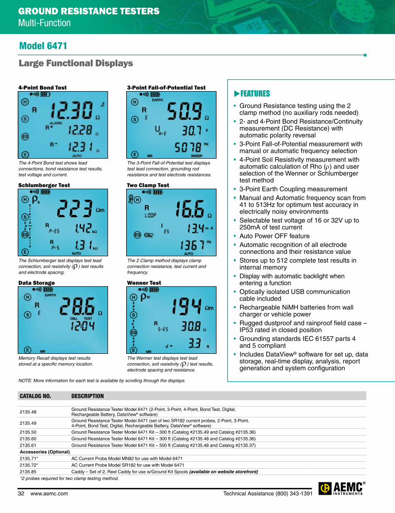
32 www.aemc.com Technical Assistance (800) 343-1391
CATALOG NO. DESCRIPTION
2135.48 Ground Resistance Tester Model 6471 (2-Point, 3-Point, 4-Point, Bond Test, Digital, Rechargeable Battery, DataView® software)
2135.49 Ground Resistance Tester Model 6471 (set of two SR182 current probes, 2-Point, 3-Point, 4-Point, Bond Test, Digital, Rechargeable Battery, DataView® software)
2135.50 Ground Resistance Tester Model 6471 Kit – 300 ft (Catalog #2135.49 and Catalog #2135.36)2135.60 Ground Resistance Tester Model 6471 Kit – 300 ft (Catalog #2135.48 and Catalog #2135.36)2135.61 Ground Resistance Tester Model 6471 Kit – 500 ft (Catalog #2135.48 and Catalog #2135.37)Accessories (Optional)2135.71* AC Current Probe Model MN82 for use with Model 64712135.72* AC Current Probe Model SR182 for use with Model 64712135.85 Caddy – Set of 2, Reel Caddy for use w/Ground Kit Spools (available on website storefront)*2 probes required for two clamp testing method.
NOTE: More information for each test is available by scrolling through the displays.
FEATURES• Ground Resistance testing using the 2
clamp method (no auxiliary rods needed)• 2- and 4-Point Bond Resistance/Continuity
measurement (DC Resistance) with automatic polarity reversal
• 3-Point Fall-of-Potential measurement with manual or automatic frequency selection
• 4-Point Soil Resistivity measurement with automatic calculation of Rho (ρ) and user selection of the Wenner or Schlumberger test method
• 3-Point Earth Coupling measurement• Manual and Automatic frequency scan from
41 to 513Hz for optimum test accuracy in electrically noisy environments
• Selectable test voltage of 16 or 32V up to 250mA of test current
• Auto Power OFF feature• Automatic recognition of all electrode
connections and their resistance value• Stores up to 512 complete test results in
internal memory• Display with automatic backlight when
entering a function • Optically isolated USB communication
cable included• Rechargeable NiMH batteries from wall
charger or vehicle power• Rugged dustproof and rainproof field case –
IP53 rated in closed position• Grounding standards IEC 61557 parts 4
and 5 compliant• Includes DataView® software for set up, data
storage, real-time display, analysis, report generation and system configuration
Model 6471
Large Functional Displays
4-Point Bond Test 3-Point Fall-of-Potential Test
Schlumberger Test
Data Storage
Two Clamp Test
Wenner Test
The 4-Point Bond test shows lead connections, bond resistance test results, test voltage and current.
The Schlumberger test displays test lead connection, soil resistivity (ρ) test results and electrode spacing.
Memory Recall displays test results stored at a specific memory location.
The 3-Point Fall-of-Potential test displays test lead connection, grounding rod resistance and test electrode resistances.
The 2 Clamp method displays clamp connection resistance, test current and frequency.
The Wenner test displays test lead connection, soil resistivity (ρ) test results, electrode spacing and resistance.
GROUND RESISTANCE TESTERS Multi-Function

Technical Assistance (800) 343-1391 www.aemc.com 33
SPECIFICATIONSMODELS 6472 & 6474ELECTRICAL 3-POINT
METHOD
4-POINT SELECTIVE METHOD
EARTH MEASUREMENT WITH 2 CLAMPS
SOIL RESISTIVITY
EARTH POTENTIAL
MEASUREMENT
DC RESISTANCE
MEASUREMENT
MEASUREMENTS WITH 6474
Range (Auto-Ranging)0.01Ω to 99.9kΩ 0.001 to 99.99Ω 0.01 to 500Ω 0.01kΩ to 99.9Ω 0.01mV to 65.00V 0.001Ω to 99.9kΩ 0.001Ω to
99.99kΩResolution
0.01 to 100Ω 0.001 to 10Ω 0.01 to 1Ω 0.01 to 100Ω 0.01 to 10mV
2 wires: 0.01 to 100Ω/
4 wires: 0.001 to 10Ω
0.001 to 10Ω
Accuracy ± (2% + 1 count) ± (2% + 1 count) ± (10% + 1 count) ± (2% + 1 count) ± (5% + 1 count) ± (2% + 2 counts) ± (5% + 1 count)No-Load Voltage 16 or 32Vrms 16 or 32Vrms 16 or 32Vrms 16 or 32Vrms 16 or 32Vrms ± 16Vdc 16 or 32VrmsMeasurement Frequency 41 to 5078Hz 41 to 5078Hz
Auto: 1611 Hz Manual: 128 Hz,
1367 Hz, 1611 Hz, 1758 Hz
41 to 128Hz 41 to 128Hz DC 41 to 5078Hz
Coupling Measurement Yes – – – – – –Auxiliary Rod Resistance Measurement 0.1Ω to 100kΩ 0.01Ω to 100kΩ – – – – 0.01Ω to 100kΩ
Voltage Interference Maximum 60VpeakSoil Resistivity
– – – Wenner and Schlumberger – – –
Type of Measurement 3 wires 4 wires – 4 wires 3 wires 2 wires or 4 wires –Measurement Current – – – – – > 200mA DC –
MECHANICALMemory/Communication 512-record memory / optical link/USBDimensions/Weight 10.7 x 9.84 x 5.04" (272 x 250 x 128mm) / Model 6472: 3.2 kg / Model 6474: 2.3 kgProtection Safety IP53 (cover closed)Electrical Safety 50V CAT IV, complies with IEC 61326-1 / IEC 61010 / IEC 61557-1-4-5
GROUND RESISTANCE TESTERS Tower Ground Resistance Testers
IP
Rated53
cover closed
TEST KITS
Ground Tester Model 6472 Kit-500 ft Includes meter, rechargeable NiMH batteries, optical USB cable, power adapter 110/240V with power
cord 115V US, two 500 ft color-coded leads on spools (red/blue), two 100 ft color-coded leads (hand-tied, green/black), one 30 ft lead (green), four T-shaped auxiliary ground electrodes, one 100 ft AEMC® tape measure, DataView® software, ground tester workbook and user manual on USB stick, carrying bag for
meter and carrying bag for kit. Catalog #2135.54
GroundFlex® Adapter Model 6474 Includes GroundFlex® Adapter Model 6474, four GroundFlex® sensors (5m) with twelve color-coded
rings, connection lead, two extension leads on H reel (black/green) with color-coded alligator clips, one extra black and green alligator clip, six BNC extension leads, calibration loop, three C-clamps, carrying
case with wheels and handle for meters, one inverter 12Vdc to 120Vac 200 watt (vehicle use) and user manual. Catalog #2136.03 (includes Cat. #2135.54)
GroundFlex® Field Kit Models 6472 & 6474
Test active towers safely without de-energizing or disconnecting
any cables
Special product features
TE
ST
LIVE SYSTEM
S
TEST TOWER LEG
GR
O
U N D R E S ISTAN
CE
DE
TE
RMINE GROUN
D
CO
N
DU C T O R Q UA
LIT
Y

34 www.aemc.com Technical Assistance (800) 343-1391
CATALOG NO. DESCRIPTION
2135.54 Ground Resistance Tester Model 6472 Kit – 500 ft (Model 6472 and Cat. #2135.37)2136.03 GroundFlex® Field Kit Model 6474 (Includes Cat. #2135.54)2136.04 GroundFlex® Adapter Model 6474 w/1 10 m GroundFlex® Sensor
2136.05 GroundFlex® Adapter Model 6474 w/1 10 m GroundFlex® Sensor (Includes Cat. #2136.04 & Cat. #2135.54)
GroundFlex® Field Kit Models 6472 & 6474
FEATURES• 3- and 4-Point Fall-of-Potential measurement
with manual or automatic frequency selection
• 4-Point soil resistivity measurement with automatic calculation of Rho (r) and user selection of the Wenner or Schlumberger test method
• 2- and 4-Wire DC resistance measurement (Bond testing) with automatic polarity reversal
• 3-Point earth coupling measurement
• Automatic frequency scan from 40 to 5078Hz for optimum test accuracy in electrically noisy environments
• Selectable test voltage limit of 16 or 32V with up to 250mA of test current
• Automatic recognition of all electrode connections and measurement of their resistance value
• Determines bonding condition of overhead ground conductors
• Auto Power OFF management
• Optically isolated USB communication
• Remote set up and operation of all measurements using DataView® software supplied
• Automatic report generation
• Rechargeable NiMH batteries from wall charger or vehicle power
• Rugged dustproof and rainproof field case — IP53 rated in closed position
• IEC 61557 parts 4 and 5 compliant
• Includes DataView® software for data storage, real-time display, analysis, report generation and system configuration
E
S
H
ES
6472RE
RS
RH
E
S
H
ES
1
2
3
46474
6472
Overheadground conductor
High voltageline
Currentinjection
rod
Potentialmeasurement
rod
4 AmpFlex® channels connected
Automatic recognition and display of input connections to match testThe connections are displayed and flash if incorrect or absent for the test selected.
Ground resistance measurement using 2 ClampsIn the event of a system with parallel ground connections, the Model 6472 is capable of accurately measuring a ground resistance using clamps only. The principle of this method involves placing 2 clamps around the ground conductor to be tested and connecting them each to the instrument. One clamp injects a known signal (32V/1367Hz) while the other clamp measures the current circulating in the loop. This method saves considerable time when ground testing because it is no longer necessary to set up auxiliary rods or to disconnect the ground connector.
Ground measurement on pylons with ground cableHigh-voltage lines are usually equipped with a ground cable to allow lighting to discharge to earth via the pylon. As all the pylons are all connected to this conductor, all the tower's resistances are in parallel. This means it is impossible to measure tower resistance using traditional 3-Point methods unless the earth cable is disconnected, which is a dangerous and time-consuming operation.
GROUND RESISTANCE TESTERS Tower Ground Resistance Testers

Technical Assistance (800) 343-1391 www.aemc.com 35
SPECIFICATIONSMODEL 6472ELECTRICAL3-Point Measurement
Range (Auto-Ranging) 0.09Ω to 99.9kΩResolution 0.01Ω to 100ΩTest Voltage Nominal 16 or 32Vrms user selectableResistance Measurement Frequency
41 to 5078Hz automatic or user selectable
Test Current Up to 250mAAccuracy ±2% of Reading + 1ct @ 128Hz
2 Clamp MeasurementRange 0.1 to 500ΩResolution 0.01 to 1ΩMeasurement Frequency Auto: 1611Hz
Manual: 128Hz-1367Hz-1611Hz-1758HzSoil Resistivity 4-Point Measurement
Test Method Wenner or Schlumberger selectable with automatic calculation of test results in Ω-meters
Range (Auto-Ranging) 0.01 to 99.99kΩ; ρ max: 999kΩm Resolution 0.01 to 100ΩTest Voltage 16 or 32V user selectableFrequency From 41 to 128Hz selectable
External Voltage MeasurementRange (Auto-Ranging) 0.1 to 65.0Vac/dc – DC to 440HzAccuracy ±2% of Reading + 1ct
Resistance Measurement (Bond Testing)Measurement Type 2-Pole (with lead resistance compensation) or
4-Pole (Kelvin sensing) user selectableRange (Auto-Ranging) 2-Pole 0.02Ω to 99.99kΩ;
4-Pole 0.02Ω to 99.99kΩAccuracy ±2% of Reading + 2ctsTest Voltage 16Vdc (+, - or auto polarity)Test Current Up to 250mA max
Data StorageMemory Capacity 512 test results (64KB)
Power Source 9.6V rechargeable battery pack (included)Recharging Source 110/220V, 50/60Hz external charger
with 18Vdc, 1.9A output
IP
Rated53
cover closed
GROUND RESISTANCE TESTERS Multi-Function
Model 6472
The Model 6472 provides an automated way to measure the value of the earth/ground using the Fall-of-Potential method and
storing measurements.
Have a better understanding about Ground Resistance
Testing
TEST KITS
ACCESSORIES
300 ft Kit: Catalog #2135.53 500 ft Kit: Catalog #2135.54
Refer to page 37 for
Model 6472 Kit descriptions Catalog #2135.35, #2135.36
& #2135.37
MN82 current probe (2mA to 10Arms) Catalog #2135.71 (optional)
SR182 current probe (0.5mA to 40Arms) Catalog #2135.72 (optional)
Used under difficult conditions such as the presence of high stray currents that
normally affect accuracy
Reel Caddy Catalog #2135.85 (optional) Set of two, for use with ground kit spools
Special product features
AU
TO
FREQUENC
Y
S E L E C TI O
N
U
P TO 25 0 m
A
G
E N E R ATI ON
AUTO REPORT
TE
ST CURRENT

36 www.aemc.com Technical Assistance (800) 343-1391
CATALOG NO. DESCRIPTION
2135.51 Ground Resistance Tester Model 6472 (2-Point, 3-Point, 4-Point, Bond Test, Digital, Rechargeable Battery, DataView® software)
2135.53 Ground Resistance Tester Model 6472 Kit – 300 ft (Model 6472 and Catalog #2135.36)2135.54 Ground Resistance Tester Model 6472 Kit – 500 ft (Model 6472 and Catalog #2135.37)Accessories (Optional)2135.71* AC Current Probe Model MN82 for use with Model 64722135.72* AC Current Probe Model SR182 for use with Model 64722135.85 Caddy – Set of 2, Reel Caddy for use w/Ground Kit Spools (available on website storefront)*2 probes required for two clamp testing method.
Model 6472
Large Functional Displays
4-Point Bond Test 3-Point Fall-of-Potential Test
Schlumberger Test
Data Storage
Frequency Selection Test
Wenner Test
The 4-Point Bond test shows lead connections, bond resistance test results, test voltage and current.
The Schlumberger test displays test lead connection, soil resistivity (ρ) test results, test electrode resistance and more.
Memory Recall displays test results stored at a specific memory location.
The 3-Point Fall-of-Potential test displays test lead connection, grounding electrode resistance, test voltage and frequency.
The Frequency selection screen displays selected test frequency and voltage for the test as well as lead connection.
The Wenner test displays test lead connection, soil resistivity (ρ) test results, electrode spacing and resistance.
FEATURES• Ground Resistance testing using the 2
clamp method (no auxiliary rods needed) using optional current probes
• 2- and 4-Wire Bond Resistance/Continuity Measurement (DC Resistance) with automatic polarity reversal
• 3-Point Fall-of-Potential measurement with manual or automatic frequency selection
• 4-Point soil resistivity measurement with automatic calculation of Rho (ρ) and user selection of the Wenner or Schlumberger test method
• 3-Point earth coupling measurement• Measures Ground Impedance at frequencies
up to 5kHz to test lightning strike protection• Manual and automatic frequency scan from
41 to 5078Hz for optimum test accuracy in electrically noisy environments
• Selectable test voltage of 16 or 32V up to 250mA of test current
• Auto Power OFF feature• Automatic recognition of all electrode
connections and their resistance value• Stores up to 512 complete test results• Display with automatic backlight when entering
a function • Optically isolated USB communication cable included • Automatic report generation including the fall
of potential plot• Rechargeable NiMH batteries from wall
charger or vehicle power• Rugged dustproof and rainproof field case –
IP53 rated in closed position• Includes DataView® software for set up, data
storage, real-time display, analysis, report generation and system configuration
GROUND RESISTANCE TESTERS Multi-Function

Technical Assistance (800) 343-1391 www.aemc.com 37
2 Clamp Method Setup
Selective 3-Point Testing of Multiple Rods
Bonding
Fall-of-Potential, Step-Touch Potential
4-Point Bonding For Very Low Resistance
Soil Resistivity
Typical DataView® Functional Displays
Ground Testers Models 6471 & 6472
OPTIONAL KITS
Catalog #2135.35 Test Kit for 3-Point testing includes
carrying bag, two 150 ft color-coded leads on spools (red/blue), two 5 ft
color-coded leads (red/blue), one 30 ft lead (green), two 14.5" T-shaped
auxiliary ground electrodes, one set of five spaded lugs and 100 ft tape
measure.
Catalog #2135.36 Test Kit for 4-Point testing includes
carrying bag, two 300 ft color-coded leads on spools (red/blue), two 5 ft
color-coded leads (red/blue), two 100 ft color-coded leads (green and black),
four 14.5" T-shaped auxiliary ground electrodes, one set of five spaded lugs
and 100 ft tape measure.
Catalog #2135.37 Test Kit for 4-Point testing includes
carrying bag, two 500 ft color-coded leads on spools (red/blue), two 5 ft color-coded
leads (red/blue), two 100 ft color-coded leads (green and black), one 30 ft lead
(green), four 14.5" T-shaped auxiliary ground electrodes, one set of five spaded
lugs and 100 ft tape measure.
150 ft Kit 300 ft Kit 500 ft Kit
GROUND RESISTANCE TESTERS Multi-Function

38 www.aemc.com Technical Assistance (800) 343-1391
Configure all functions of the Models 6417, 6471 & 6472
• Run tests and analyze real-time data from your PC
• Configure all test functions and parameters from your PC
• Customize views, templates and reports to your exact needs
• Display Fall-of-Potential plots, tabular listings of test results, resistance vs. frequency plots, soil resistivity and bonding tests
• Print reports using standard or custom templates you design
• Free updates are available on our website www.aemc.com
DataView® software provides a convenient way to configure and control ground resistance tests from your computer. Through the use of clear and easy-to-use tabbed dialog boxes, all ground tester functions can be configured and tests can be initiated. Results can be displayed in real-time and stored in your PC. Reports may be printed along with the operator’s comments and analysis.
DATAVIEW® Software for Ground Resistance Testers
Data Analysis and Reporting Software for Ground Testers

Technical Assistance (800) 343-1391 www.aemc.com 39
AEMC MODEL
NUMBER
AEMC CATALOG NUMBER
RESISTANCE RANGE
POWER SOURCE
2 POINT TEST
3 POINT TEST
4 POINT/
SELECTIVE
SOIL RESISTIVITY
TEST
EARTHCOUPLING
2 CLAMP
BONDING DISPLAYVOLTAGE
INDICATIONINDUCTANCE INDICATION
SWEEP FREQUENCY
6416 2141.01 0.01 to 1500Ω Battery Clamp-On Ground Resistance Tester — — ** Digital
Voltage Displayed (noise icon,
buzzer)
—
6417 2141.02 0.01 to 1500Ω Battery
Clamp-On Ground Resistance Tester w/Alarm, Memory & Bluetooth
communication— — ** Digital
Voltage Displayed (noise icon,
buzzer)
—
GroundFlex® Field Kit Models
6472 & 6474
2136.03 0.001Ω to 99.99kΩ
Rechargeable Battery — — Digital
Value Displayed
—
6471 2135.49 0.01 to 99.99kΩ
Rechargeable Battery Digital
Value Displayed
— —
6471 Kit 300FT
2135.50 0.01 to 99.99kΩ
Rechargeable Battery Digital
Value Displayed
— —
6472 2135.51 0.01 to 99.99kΩ
Rechargeable Battery Digital
Value Displayed
— 6472 Kit 300FT
2135.53 0.01 to 99.99kΩ
Rechargeable Battery Digital
Value Displayed
— 6472 Kit 500FT
2135.54 0.01 to 99.99kΩ
Rechargeable Battery Digital
Value Displayed
—
4620 2130.43 0.0 to 1999Ω Battery — — — — Digital LED/Buzzer — —
4620 Kit150FT
2135.19 0.0 to 1999Ω Battery — * — — — Digital LED/Buzzer — —
4620 Kit300FT
2135.20 0.0 to 2000Ω Battery — — — — Digital LED/Buzzer — —
4620 Kit500FT
2135.21 0.0 to 1999Ω Battery — — — — Digital LED/Buzzer — —
4630 2130.44 0.0 to 1999Ω
Rechargeable Battery — — — — Digital LED/Buzzer — —
4630 Kit 150FT
2135.22 0.0 to 1999Ω
Rechargeable Battery — * — — — Digital LED/Buzzer — —
4630 Kit 300FT
2135.23 0.0 to 1999Ω
Rechargeable Battery — — — — Digital LED/Buzzer — —
4630 Kit 500FT
2135.24 0.0 to 1999Ω
Rechargeable Battery — — — — Digital LED/Buzzer — —
3620 2114.90 0.50 to 1000Ω Battery — — — — — Analog LED — —
3620 Kit150FT
2135.10 0.50 to 1000Ω Battery — — — — — Analog LED — —
3620 Kit300FT
2135.11 0.50 to 1000Ω Battery — — — — — Analog LED — —
3640 2114.92 0.0 to 1999Ω Battery — — — — — Digital LED — —
3640 Kit150FT
2135.13 0.0 to 1999Ω Battery — — — — — Digital LED — —
3640 Kit300FT
2135.14 0.0 to 1999Ω Battery — — — — — Digital LED — —
* Performing soil resistivity tests with this kit requires two additional auxiliary electrodes not supplied in the 150 ft kit and one additional test lead.** Clamp-on Ground Resistance Tester can measure system continuity inclusive of all bonding points.
GROUND RESISTANCE TESTER Selection Chart

40 www.aemc.com Technical Assistance (800) 343-1391
SPECIFICATIONSMODEL CA7024MEASUREMENTSRange @ Vp = 70% 6000 ft or 2000m (selectable)
Resolution 0.1 ft up to 100 ft, then 1 ft (0.1m up to 100m, then 1m)
Accuracy ±2% of Reading
Minimum Cable Length 12 ft (4m)
Cable Library Built-in, user selectable and user programmableVelocity of Propagation (Vp) Adjustable from 0 to 99%
Output Pulse 5V (peak to peak) into open circuit; nanosecond rise Step Function
Output Impedance Automatic compensation
Display Resolution 128 x 64 pixel graphical LCD
Tone Generator Oscillating 810 to 1110Hz
Voltage Warning Triggers at >10VAC/DC
Power Source Four 1.5V AA Alkaline batteries (included)
Auto Power OFF After three minutes
Weight 12 oz (350g)
CATALOG NO. DESCRIPTION
2127.80 Fault Mapper Model CA7024 (Cable Length Meter & Fault Locator – Alphanumeric TDR)
Accessories (Optional)
2127.76 Tone Receiver/Cable Tracer Model TR03
Finds opens, shorts and cable length
PRODUCT INCLUDES
Soft carrying case, BNC pigtail cable with alligator clips, four 1.5V AA batteries and user manual.
Model CA7024
Tone Receiver Cable Tracer Model TR03
available as an accessory
CABLE TESTERSFault Mapper Cable Length Meter & Fault Locator Alphanumeric TDR
Special product features
FEATURES• Hand-held Cable Length Meter and Fault Locator
for multiple conductor cables• Detects opens and shorts and the distance to them from
one end of the cable• Measure cable length up to 6000 ft or 2000m (selectable)• Automatic cable impedance compensation• Built-in library of most common cables
and their Velocity of Propagation (Vp)• Manual selection of Vp for all cables not found in library• User programmable cable library with
15 storage positions• Vp setting displayed along with length and
cable type (if in library)• Built-in tone generator for tracing and locating cables• Large high-visibility blue electroluminescent backlit display
Tone Receiver/Cable Tracer Model TR03 (optional):• Compatible with Models CA7024, CA7027 and CA7028• One button operation• Volume control• Audio output
DETECTS
G
EN ER ATO
R
CA
BLE L ENGT
H
BUILT-IN TONE
MEASURES
OP
ENS & S HO
RT
S

Technical Assistance (800) 343-1391 www.aemc.com 41
SPECIFICATIONSMODEL CA7027MEASUREMENTSRange @ Vp = 70% 23, 49, 98, 197, 394, 820, 1640, 3280,
6560, 9850, 19000 ftRange Selection Manual range controlAccuracy ±1% of rangeResolution Approximately 1% of selected rangeMinimum Cable Length 5 ft (1.5m)
Sensitivity Minimum 3 pixel return on a fault at 4km on 0.6mm 0, PE, TP
Velocity of Propagation (Vp) Adjustable from 1% to 99%
Output Pulse +5V peak to peak into an open circuitOutput Impedance Selectable between 25, 50, 75 & 100ΩOutput Pulse Width 3 ns to 3 ms, Automatic with rangeScan Rate 2 scans / second or scan heldTone Generator Oscillating tone 810 to 1110HzVoltage Protection 250Vac
Power Supply Four 1.5V AA alkaline batteriesBattery Life 60 hours continuous scanningAuto Power OFF Selectable 1, 2, 3, 5 minutes or disabledWeight (with battery) 12oz (350g)
CATALOG NO. DESCRIPTION
2127.84 Fault Mapper Pro® Model CA7027 (Telephone Cable Tester / Graphical TDR)
Accessories (Optional)
2127.76 Tone Receiver/Cable Tracer Model TR03
Maps and pinpoints the locations of faults on power and communication cables
PRODUCT INCLUDES
Soft carrying case, 4mm color-coded banana plugs with alligator clips, four 1.5V AA
batteries and user manual.
Modelo CA7027
CABLE TESTERS Fault Mapper Pro® Telephone Cable Tester / Graphical TDR
Learn the importance of a structured
cable tester
Tone Receiver/Cable Tracer Model TR03 is available as an accessory (see page 40)
Special product features
FEATURES• 11 range scales indicating cable faults and
terminations up to 19,000 ft (6000m) in feet or meters
• Unique graphical and digital display of fault information and length
• Detects opens, shorts, taps, faulty taps, bridge taps, splitters, high resistance, wet cables, splices and more
• Identifies impedance mismatches
• Works with twisted pair, parallel and coaxial cable
• Dead band less than 9 ft
• Selectable cable impedance (25Ω, 50Ω, 75Ω, 100Ω)
• Over-voltage protection up to 250V
• Adjustable cursor assists in locating faults and termination
• Built-in tone generator for tracing and locating cables
• Large high-visibility blue electroluminescent backlit display
GR
APHIC DISPLA
Y
M
ISMATCHES
19 ,0 0 0 f t
DE
TEC
TS IMPEDANC
E
ME
ASU
RES CABLE T
O
OF FAULTS
~

42 www.aemc.com Technical Assistance (800) 343-1391
CATALOG NO. DESCRIPTION
2127.82 Wire Mapper Pro Model CA7028 (LAN Cable Tester)
Accessories (Optional)
2127.76 Tone Receiver/Cable Tracer Model TR03
SPECIFICATIONSMODEL CA7028MEASUREMENTSRange 500 ft or 150m (selectable)
Accuracy ±5% of Reading
Cable Type UTP, STP, FTP and SSTP
Faults Indicated Short Circuit Pair, Open Circuit Wire, Short Between Pairs,Split/Cross Pairs,
Pair Reversals, Shield Continuity
Fault Location Near end, remote end, or distance to fault
Fault Display All fault and setting info displayed textually and graphically
Wiring Schemes TIA 568A/B, USOC and ISDN
Service Indication Telephone, 10BaseT, 100Mbit+, Token Ring
Voltage Warning Audible and visual warning of TNV (Telecom Network Voltage)
Test Inhibit Inhibits testing in the presence of live voltages
Tone Generator Oscillating 810 to 1110Hz
Power Source Four 1.5V AA Alkaline batteries (included)
Display Backlight Blue electroluminescent
Remote Display Green/Red Pass/Fail LED
Auto Power OFF After three minutes
Weight Main unit: 12 oz (350g); Remote unit: 1.5 oz (40g)
The only wire-mapper in its class with graphical and digital display of fault type and fault location
FEATURES• Hand-held LAN Cable Mapping and
Troubleshooting Tester• Indicates all common wiring faults including split pairs,
shorts, opens, reversed pairs and crossed wires• Unique graphical and digital display of fault
information and length• Active remote unit indicates Pass/Fail at remote
end by Green/Red LED during the test• Indicates distances to opens and shorts and
identifies location• Display fault location up to 500 ft or 150m (selectable)• Built-in tone generator for tracing and locating cables• Built-in service check function to detect telephone,
10BaseT, 100Mbit+ and Token Ring• Visual and audible warning of live telephone network
voltages• Works with all category cables• Rugged design weighs less than 12 oz (350g)• Large high-visibility blue electroluminescent
backlit display • Complete with remote unit and mini patch leads• Works with TIA 568A/B, USOC and ISDN
wiring schemes
Model CA7028
Soft carrying case, remote ID (#1), two patch cords, four 1.5V AA batteries, remote unit and user manual.
PRODUCT INCLUDES
Tone Receiver/Cable Tracer Model TR03 is available as an accessory (see page 40)
CABLE TESTERS Wire Mapper Pro LAN & Cable Tester Model CA7028
Special product features
DIS
PLAY OF CAB
LE
OP
ENS & SHORT
S
DETECTS
T
ERMIN ATION
G
EN ER ATO
R
BUILT-IN TONE
' '''

Technical Assistance (800) 343-1391 www.aemc.com 43
SPECIFICATIONSMODEL CL601ELECTRICALChannels One
Input Split CT – AC Current
Measurement Range 0 to 600Aac
Resolution 0.1A
Accuracy (50/60Hz) 0 to 5A: unspecified 5 to 50A: ±(1% of Reading + 1A)
50 to 400A: ±(1% of Reading + 0.5A) 400 to 600A: ±(3% of Reading + 1A)
Sample Rate 64 samples/cycle
Storage Rate Programmable from 8 every second to 1 every day
Storage Modes Start/Stop, FIFO, Extended Recording Mode (XRM™)* and Alarm
Recording Length 15 minutes to 8 weeks, programmable using DataView®
Memory 240,000 measurements (512KB) - The recorded data is stored in non-volatile memory and will be retained even if the
battery is low or removed.
Communication USB 2.0 optically isolated
Power Source 2 x 1.5V AA-cell Alkaline batteries (included)
Battery Life 100 hours to >45 days (dependent on sample rate and recording length)
MECHANICALDimensions 9.25 x 4.0 x 1.63" (235 x 102 x 41mm)
Max Conductor Size 1 conductor - Ø 1.42" (36mm) 2 conductor - Ø 1.00" (25mm) ea
Weight (with battery) 17.1 oz (485g)
Case UL94-V0
Vibration IEC 68-2-6 (1.5mm, 10 to 55Hz)
Shock IEC 68-2-27 (30G)
Drop IEC 68-2-32 (1m)
CATALOG NO. DESCRIPTION
2126.01 Simple Logger® II Model CL601 (1-Channel, TRMS Clamp-On, 600Aac, DataView® software)
IP
Rated40
Model CL601
Designed for plant and field service applications and for use in harsh
environments
DATA LOGGERSSimple Logger® II TRMS Clamp-On Current
FEATURES• 0 to 600Arms• True RMS measurements• Self contained, no exposed connections• Overload indication• Optically isolated USB 2.0 communication cable included • One button operation• Alarm function• 5 LED indicators quickly and clearly display logger status• Powered by standard Alkaline batteries• Includes FREE DataView® software for data storage, real-time display, analysis and report generation• EN 61010-1; 300V CAT IV, 600V CAT III
APPLICATIONS• Machine load monitoring
• HVAC troubleshooting
• Load profiling
• Electrical troubleshooting
• Start-Stop time stamping
*Extended Recording Mode (XRM™)This unique recording mode provides the opportunity to continuously record over long
periods of time by reducing the stored samples of the oldest data and maintaining matching resolution for the newest data. Each time the memory fills up using XRM™
every other of the oldest stored samples is discarded making room for newer samples. This process continues until the recording is manually stopped.
Special product features
LOGGER &
O
P E R ATI O
N
6 0 0 A A
C
CL
A M P M ETER
O
NE BUTTON
RE
CORDS UP TO
'' ''

44 www.aemc.com Technical Assistance (800) 343-1391
SPECIFICATIONSMODELS L101 L102 L111ELECTRICALChannels One Two OneInput Connection BNC One BNC
connector per channel
Two recessed banana jacks
Measurement Range 0 to 1Vac (probe dependent) 0 to 1Aac (probe dependent)Resolution 0.1mV 0.1mAAccuracy (50/60Hz)
0 to 10mV: unspecified 10 to 50mV:
±(0.5% of Reading + 1mV) 50 to 1000mV:
±(0.5% of Reading + 0.5mV)
0 to 10mA: unspecified 10 to 50mA:
±(0.5% of Reading + 1mA) 50 to 1000mA:
±(0.5% of Reading + 0.5mA)Input Impedance 800kΩ 1ΩSample Rate 64 samples/cycleStorage Rate Programmable from 8 every second to 1 every dayStorage Modes Start/Stop, FIFO, Extended Recording Mode (XRM™) and AlarmRecording Length 15 minutes to 8 weeks, programmable using DataView®
Memory 240,000 measurements (512KB) The recorded data is stored in non-volatile memory and will be
retained even if the battery is low or removed.Communication USB 2.0 optically isolatedPower Source 2 x 1.5V AA-cell Alkaline batteries (included)Battery Life 100 hours to >45 days
(dependent on sample rate and recording length)
MECHANICALDimensions 5.38 x 2.75 x 1.28"
(136 x 70 x 32mm)5.18 x 2.75 x 1.28" (132 x 70 x 32mm)
Max Conductor Size Current probe dependentWeight (with battery) 6.4 oz (181g) 6.64 oz (188g)Case UL94-V0Vibration IEC 68-2-6 (1.5mm, 10 to 55Hz)Shock IEC 68-2-27 (30G)Drop IEC 68-2-32 (1m)
CATALOG NO. DESCRIPTION
2126.02 Simple Logger® II Model L101 (1-Channel, TRMS, 0 to 1Vac, DataView® software)
2126.03 Simple Logger® II Model L102 (2-Channel, TRMS, 0 to 1Vac, DataView® software)
2126.04 Simple Logger® II Model L111 (1-Channel, TRMS, 0 to 1Aac, DataView® software)
IP
Rated40
One channel loggers with the ability to perform a variety of recording tasks
Models L101, L102 & L111
FEATURES• Compatible standard current probes with voltage output and BNC connection (Models L101 & L102) (see page 56 & 57 - sold separately)• Fused input (Model L111)• Compatible with standard AC current probes with current output and banana plug connection (Model L111)• 2 inputs (Model L102)• 64 samples per cycle• Programmable storage rates from 8 every second to 1 every day• 4 user selectable storage modes• Stores up to 240,000 measurements in non-volatile memory• Powered by standard Alkaline batteries • Lightweight, compact, fits anywhere• 5 LED indicators quickly and clearly display logger status• Includes FREE DataView® software for data storage, real-time display, analysis and report generation• Optically isolated USB 2.0 communication cable included• EN 61010-1; 50V CAT III
APPLICATIONS ( MODELS L101 & L111 )• Load profiling• Fault current detection• Intermittent problem detection• Demand recording• Neutral current monitoring• Harmonic current recording using DataView® software• Metering CT resizing• Start-Stop time stamping
APPLICATIONS ( MODEL L102 )• Split phase load monitoring• Neutral & ground current monitoring• Intermittent problem detection• Harmonic current monitoring using DataView® software• Machine load monitoring• Start-Stop time stamping
See pages 56 & 57 for current probe selection
DATA LOGGERS Simple Logger® II TRMS Current

Technical Assistance (800) 343-1391 www.aemc.com 45
SPECIFICATIONSMODELS L261 L481ELECTRICALChannels One
Input Connection Two recessed 4mm safety banana jacks
Measurement Range 0 to 600Vac/dc -850 to ±850Vdc
Resolution 0.1V
Accuracy (50/60Hz) 0 to 5V: unspecified 5 to 50V:
± (0.5% of Reading + 1V) 50 to 600V:
± (0.5% of Reading + 0.5V)
0 to 5V: unspecified 5 to 50V:
± (0.5% of Reading + 1V) 50 to 850V:
± (0.5% of Reading + 0.5V)
Input Impedance 40MΩSample Rate 64 samples/cycle Maximum of 8 per second
Storage Rate Programmable from 8 every second to 1 every day
Storage Modes Start/Stop, FIFO, Extended Recording Mode (XRM™) and Alarm
Recording Length 15 minutes to 8 weeks, programmable using DataView®
Memory 240,000 measurements (512KB) The recorded data is stored in non-volatile memory and will be retained even if the battery is low or removed.
Communication USB 2.0 optically isolated
Power Source 2 x 1.5V AA-cell Alkaline batteries (included)
Battery Life 100 hours to >45 days (dependent on sample rate and recording length)
MECHANICAL
Dimensions 4.94 x 2.75 x 1.28" (125 x 70 x 32mm)
Weight (with battery) 6.4 oz (181g)
Case UL94-V0
Vibration IEC 68-2-6 (1.5mm, 10 to 55Hz)
Shock IEC 68-2-27 (30G)
Drop IEC 68-2-32 (1m)
CATALOG NO. DESCRIPTION
2126.05 Simple Logger® II Model L261 (1-Channel, TRMS, 600Vac/dc, DataView® software)
2126.25 Simple Logger® II Model L481 (1-Channel, ±850Vdc, DataView® software)
IP
Rated40
PRODUCT INCLUDES
Set of two color-coded 5 ft voltage leads, color-coded alligator clips (red/black), USB type A to 5 pin Mini-B, and USB
stick supplied with DataView® software and user manual.
DATA LOGGERS Simple Logger® II TRMS Voltage
FEATURES• TRMS voltage recording up to 600Vac/dc (Model L261)• Bipolar voltage recording up to ±850Vdc (Model L481) • AC: 64 samples per cycle and DC: 8 samples per sec (Model L261) • Programmable storage rates from 8 every second to 1 every day• 4 user selectable storage modes• Stores up to 240,000 measurements in non-volatile memory• Powered by standard Alkaline batteries • Lightweight, compact, fits anywhere• 5 LED indicators quickly and clearly display logger status• Includes FREE DataView® software for data storage, real-time display, analysis and report generation• Optically isolated USB 2.0 communication cable included• EN 61010-1; 300V CAT IV; 600V CAT III
APPLICATIONS ( MODEL L261 )• Surge and Sag recording• Long term supply monitoring• Industrial, commercial and residential monitoring• Monitor voltage harmonics• Find intermittent voltage problems• Machine monitoring
APPLICATIONS ( MODEL L481 )• Rail voltage monitoring• Long term supply monitoring• Find intermittent voltage problems• Machine monitoring• Windmill monitoring
600Vac/dc Model L261 & ±850Vdc Model L481
One channel loggers for voltage measuring, monitoring and troubleshooting

46 www.aemc.com Technical Assistance (800) 343-1391
IP
Rated40
SPECIFICATIONSMODEL L562ELECTRICALChannels TwoConnection Current Channel Voltage ChannelInput Connection BNC Two recessed banana jacksInput Range* 0 to 1Vac (for use with current
probes with a voltage output) 0 to 600Vac
Resolution 0.1mV 0.1VAccuracy (50/60Hz) 0 to 10mV unspecified
10 to 50mV: ±(0.5% of Reading + 1mV)
50 to 1000mV: ±(0.5% of Reading + 0.5mV)
0 to 5V unspecified5 to 50V:
±(0.5% of Reading + 1V)50 to 600V:
±(0.5% of Reading + 0.5V)
Input Impedance 800kΩ 40MΩMaximum Input Voltage*** 5Vrms or ± 7.07V peak 1.2 x 600VSample Rate 64 samples/cycleStorage Rate Programmable from 8 every second to 1 every dayStorage Modes Start/Stop, FIFO, Extended Recording Mode (XRM™) and AlarmRecording Length 15 minutes to 8 weeks, programmable using DataView®
Memory 240,000 measurement (512KB). The recorded data is stored in non-volatile memory and will be retained even if the battery is low or removed.
Communication USB 2.0 optically isolatedPower Source** 2 x 1.5V AA-cell Alkaline batteries (included)Battery Life 100 hours to > 45 days
(dependent on sample rate and recording length)
MECHANICALDimensions 5.38 x 2.75 x 1.28" (136 x 70 x 32mm)Max Conductor Size Current probe dependentWeight (with battery) 6.4 oz (181g)Case UL94-VOVibration IEC 68-2-6 (1.5mm, 10 to 55Hz)Shock IEC 68-2-27 (30G)Drop IEC 68-2-32 (1m)
*The native measurement of the instrument is voltage. This voltage is scaled to display current corresponding to the users probe selection. This accuracy specification does not account for probe errors.
**A memory backup provides backup power while the batteries are being changed.
***Input level beyond this range may damage the instrument.
CATALOG NO. DESCRIPTION
2126.35 Simple Logger® II Model L562 (2-Channel, TRMS, Voltage & Current, DataView® software)
PRODUCT INCLUDES
Set of two color-coded 5 ft voltage leads, color-coded alligator clips (red/black), USB type A to 5 pin Mini-B, and USB stick supplied with DataView® software and user manual.
FEATURES• 2 input channels• Voltage: 0 to 600VAC TRMS• Current: compatible with voltage output AC current probes with voltage outputs (see page 56 & 57 - sold separately)• 64 samples per cycle• Records Arms, Vrms & VA (VA displays in DataView® software)• 4 user selectable storage modes• Programmable storage rates from 8 every second to 1 every day • Stores up to 240,000 measurements in non-volatile memory• Powered by standard Alkaline batteries• Lightweight, compact, fits anywhere• 5 LED indicators quickly and clearly display logger status• Includes FREE DataView® software for data storage, real-time display, analysis and report generation• Optically isolated USB 2.0 communication cable included• Complies with EN 61010-1; 300V CAT IV; 600V CAT III (a safety rated current probe is required)
APPLICATIONS• Single phase power monitoring• Residential, commercial, industrial, troubleshooting• Find sags and surges• Track energy usage• Start-Stop time stamping
Model L562
Two input channel logger capable of recording Arms, Vrms and VA
See pages 56 & 57 for compatible current probes (sold separately)
DATA LOGGERS Simple Logger® II TRMS Voltage & Current

Technical Assistance (800) 343-1391 www.aemc.com 47
SPECIFICATIONSMODEL ML912ELECTRICAL
Channels Two
Input Captive MiniFlex® AC Current Flexible Sensors
Range 0.5 to 100Aac 5 to 1000Aac
Accuracy (50/60Hz)
0 to 1A unspecified 1 to 100A:
±(1% of Reading + 0.5A)
0 to 5A unspecified 5 to 1000A:
±(1% of Reading + 1A)
Resolution 0.1A
Sample Rate 64 samples/cycle
Storage Rate Programmable from 8 every second to 1 every day
Storage Modes Start/Stop, FIFO, Extended Recording Mode (XRM™) and Alarm
Recording Length 15 minutes to 8 weeks, programmable using DataView®
Memory 240,000 measurement (512KB) The recorded data is stored in non-volatile memory
and will be retained even if the battery is low or removed.
Communication USB 2.0 optically isolated
Power Source 2 x 1.5V AA-cell Alkaline batteries (included)
Battery Life 100 hrs to >45 days (dependent on storage rate/recording length)
MECHANICAL
Dimensions 4.95 x 2.75 x 1.28" (136 x 70 x 32mm) w/o Sensor
Max Conductor Size Sensor: 6" (152mm)/Cable: 6 ft (2m)
Weight (with battery) 8.67 oz (245g)
Case UL94-V0
Vibration IEC 68-2-6 (1.5mm, 10 to 55Hz)
Shock IEC 68-2-27 (30G)
Drop IEC 68-2-32 (1m)
CATALOG NO. DESCRIPTION
2126.37 Simple Logger® II Model ML912 (2-Channel, TRMS, MiniFlex®, 100/1000Aac, DataView® software)
R AT I N G
SAFETY
IP
Rated40
FEATURES• Includes two integral MiniFlex® flexible current probes that will measure from 0.5A to 1000A TRMS with 0.1A resolution• Dual range 100/1000A user selectable per channel in software• 64 samples per cycle• Programmable storage rates from 8 every second to 1 every day• 4 user selectable storage modes• Stores up to 240,000 measurements in non-volatile memory• Powered by standard Alkaline batteries• Lightweight, compact, fits anywhere• 5 LED indicators quickly and clearly display logger status• Includes FREE DataView® software for data storage, real-time display, analysis and report generation• Optically isolated USB 2.0 communication cable included• EN 61010-1; 600V CAT IV, 1000V CAT III
APPLICATIONS• Single and Split phase load monitoring • Neutral and ground current monitoring • Intermittent problem detection • Harmonic current monitoring using DataView® software • Machine load monitoring • Fault current detection• Load profiling
DATA LOGGERS Simple Logger® II TRMS Current
Dual Channel MiniFlex® Model ML912
Two channel AC recording logger incorporates two selectable
measurement ranges

48 www.aemc.com Technical Assistance (800) 343-1391
CATALOG NO. DESCRIPTION
2126.06 Simple Logger® II Model L322 (2-Channel, 4 to 20mAdc Current, DataView® software)
2126.07 Simple Logger® II Model L432 (2-Channel, DC ±100mV/1V/10Vdc, DataView® software)
SPECIFICATIONSMODELS L322 L432ELECTRICAL
Channels Two
Input Connection One 4-position removable screw-type terminal blockMeasurement Range
-20 to +20mAdc
±100mV/1V/10Vdc (selectable through
DataView® software)
Resolution 0.01mA 0.1mV - 1mV - 10mVAccuracy (DC and 50/60Hz)
Range 1 (0.25% of Reading +0.05mA) ±(0.5% of Reading +1mV)
Range 2 – ±(0.5% of Reading +1mV)
Range 3 – ±(0.5% of Reading +10mV)
Input Impedance50Ω 100mV/1V: 80kΩ
10V: 800kΩ
Sample Rate 8 samples taken at storage interval
Storage Rate Programmable from 8 every second to 1 every day
Storage Modes Start/Stop, FIFO, Extended Recording Mode (XRM™) and Alarm
Recording Length 15 minutes to 8 weeks, programmable using DataView®
Memory 240,000 measurements (512KB) The recorded data is stored in non-volatile memory and will be retained even if the battery is low or removed.
Communication USB 2.0 optically isolated
Power Source 2 x 1.5V AA-cell Alkaline batteries (included)Battery Life 100 hours to >45 days
(dependent on sample rate and recording length)
MECHANICAL
Dimensions 5.45 x 2.75 x 1.28" (136 x 70 x 32mm)
Weight (with battery) 6.4 oz (181g)
Case UL94-V0
Vibration IEC 68-2-6 (1.5mm, 10 to 55Hz)
Shock IEC 68-2-27 (30G)
Drop IEC 68-2-32 (1m)
IP
Rated40
FEATURES• 2 independent input channels• -20 to +20mADC (Model L322)• User-selectable ranges of ± 100mV; ± 1V and ± 10VDC per channel (Model L432)• Programmable storage rates from 8 every second to 1 every day• 4 user selectable storage modes• Stores up to 240,000 measurements in non-volatile memory• Powered by standard Alkaline batteries• Lightweight, compact, fits anywhere• 5 LED indicators quickly and clearly display logger status• Includes FREE DataView® software for data storage, real-time display, analysis and report generation• Optically isolated USB 2.0 communication cable included• EN 61010-1; 50V CAT III
APPLICATIONS ( MODEL L322 )• Process control monitoring and troubleshooting• Profile temperature, pressure, flow and other parameters directly• General purpose DC current monitoring• And many more
APPLICATIONS ( MODEL L432 )• Circuit design troubleshooting• Sensor monitoring• Battery testing• Power supply profiling• And many more
4 to 20mAdc Current Model L322 & DC Voltage Model L432
Two channel logger has the ability to perform a variety of recording tasks with easy and intuitive setup
DATA LOGGERS Simple Logger® II TRMS Current & Voltage

Technical Assistance (800) 343-1391 www.aemc.com 49
CATALOG NO. DESCRIPTION
2126.08 Simple Logger® II Model L642 (2-Channel, Temperature Thermocouple, DataView® software)
Accessories (Optional)
2126.46 Thermocouple-Needle (12 x 5.9", K Type, -58° to 1292°F)
SPECIFICATIONSMODEL L642ELECTRICALChannels Two
Input Connection Two miniature, thermocouple connectors
Measurement Range:JKTNERS
°F (°C)-346 to +2192 (-210 to +1200) -328 to +2501 (-200 to +1372) -328 to +752 (-200 to +400)
-328 to +2372 (-200 to +1300) -238 to 1742 (-150 to +950)
32 to 3212 (0 to 1767) 32 to 3212 (0 to 1767)
Resolution 0.1° C/F < 1000° C/F; 1° ≥ 1000° C/F
Accuracy ±(0.1% to 0.2% of Reading + 0.6° to 1°) depending on the range and T/C type
Sample Rate 8 samples taken at storage interval
Storage Rate Programmable from 5s to 1 per day
Storage Modes Start/Stop, FIFO, Extended Recording Mode (XRM™) and Alarm
Recording Length 15 minutes to 8 weeks, programmable using DataView®
Memory 240,000 measurements (512KB) The recorded data is stored in non-volatile memory and will be retained even if the battery is low or removed.
Communication USB 2.0 optically isolated
Power Source 2 x 1.5V AA-cell Alkaline batteries (included)
Battery Life 100 hours to >45 days (dependent on sample rate and recording length)
MECHANICAL
Dimensions 4.94 x 2.75 x 1.28" (125 x 70 x 32mm)
Weight (with battery) 7 oz (200g)
Case UL94-V0
Vibration IEC 68-2-6 (1.5mm, 10 to 55Hz)
Shock IEC 68-2-27 (30G)
Drop IEC 68-2-32 (1m)
IP
Rated40
Model L642
DATA LOGGERS Simple Logger® II Thermocouple
2 channel specialty logger for recording temperature from thermocouple inputs
PRODUCT INCLUDES ACCESSORY
Catalog #2126.47 (1m) K Type, -58° to 480°F
Catalog #2126.46 (optional) (12 x 5.9") K Type, -58° to 1292°F
Thermocouple-Flexible Thermocouple-Needle
FEATURES• 2 input channels
• User-selectable thermocouple types J, K, T, N, E, R, and S (not included)
• Programmable storage rates from 1 every 5 seconds to 1 every day
• 4 user selectable storage modes
• Stores up to 240,000 measurements in non-volatile memory
• Powered by standard Alkaline batteries
• 5 LED indicators quickly and clearly display logger status
• Includes FREE DataView® software for data storage, real-time display, analysis and report generation
• Optically isolated USB 2.0 communication cable included
• EN 61010-1; 50V CAT III
APPLICATIONS• HVAC monitoring• Process monitoring• Refrigeration monitoring• And many more
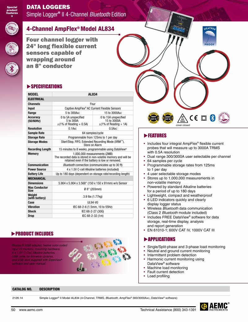
50 www.aemc.com Technical Assistance (800) 343-1391
DATA LOGGERS Simple Logger® II TRMS Clamp-On Current
Special product features
PRODUCT INCLUDES
Bluetooth USB adapter, twelve color-coded input ID markers, mounting hardware, 4 x 1.5V C-Cell Alkaline batteries, USB cable for firmware updates, and USB stick supplied with DataView® software and user manual.
CATALOG NO. DESCRIPTION
2126.14 Simple Logger® II Model AL834 (4-Channel, TRMS, Bluetooth, AmpFlex® 300/3000Aac, DataView® software)
FEATURES• Includes four integral AmpFlex® flexible current probes that will measure up to 3000A TRMS with 0.5A resolution• Dual range 300/3000A user selectable per channel• 64 samples per cycle• Programmable storage rates from 125ms to 1 per day• 4 user selectable storage modes• Stores up to 1,000,000 measurements in non-volatile memory• Powered by standard Alkaline batteries for a period of up to 180 days• Lightweight, compact and weatherproof• 6 LED indicators quickly and clearly display logger status• Wireless Bluetooth data communication (Class 2 Bluetooth module included)• Includes FREE DataView® software for data storage, real-time display, analysis and report generation• EN 61010-1; 600V CAT IV, 1000V CAT III
APPLICATIONS• Single/Split-phase and 3-phase load monitoring • Neutral and ground current monitoring • Intermittent problem detection • Harmonic current monitoring using DataView® software • Machine load monitoring • Fault current detection• Load profiling
4-Channel AmpFlex® Model AL834
DATA LOGGERS Simple Logger® II 4-Channel Bluetooth Edition
SPECIFICATIONSMODEL AL834ELECTRICALChannels FourInput Captive AmpFlex® AC Current Flexible SensorsRange 5 to 300Aac 15 to 3000Aac
Accuracy (50/60Hz)
0 to 5A unspecified 5 to 300A:
±(1% of Reading + 0.5A)
0 to 15A unspecified 15 to 3000A:
±(1% of Reading + 1A)Resolution 0.1Aac 0.5Aac
Sample Rate 64 samples/cycleStorage Rate Programmable from 125ms to 1 per dayStorage Modes Start/Stop, FIFO, Extended Recording Mode (XRM™),
Store on AlarmRecording Length 15 minutes to 8 weeks, programmable using DataView®
Memory 1,000,000 measurements (2MB) The recorded data is stored in non-volatile memory and will be
retained even if the battery is low or removed.Communication Bluetooth connection (communicates up to 30 ft)Power Source 4 x 1.5V C-cell Alkaline batteries (included)Battery Life Up to 180 days (dependent on storage rate/recording length)
MECHANICALDimensions 5.904 x 5.904 x 3.568" (150 x 150 x 91mm) w/o SensorMax Conductor Size Ø 8" (203mm)
Weight (with battery) 3.9 lbs (1.77kg)
Case UL94-V0Vibration IEC 68-2-6 (1.5mm, 10 to 55Hz)Shock IEC 68-2-27 (30G)Drop IEC 68-2-32 (1m)
Four channel logger with 24" long flexible current sensors capable of wrapping around an 8" conductor
Special product features
CO
M
M U N I C ATION
CU
R
RE N T P R O
BE
S
S
EL E C TI O
N
4 INTEGRAL
WIRELESS
U
SER RANGE
R AT I N G
SAFETY
IP65
Rated
cover closed

Technical Assistance (800) 343-1391 www.aemc.com 51
POWER QUALITY ANALYZERS, METERS & LOGGERS Three-Phase Power Quality Analyzer
GROUND RESISTANCE TESTER Multi-Function
Special product features
DATA LOGGERS Simple Logger® II TRMS Current
PRODUCT INCLUDES
Bluetooth USB adapter, twelve color-coded input ID markers, mounting hardware, 4 x 1.5V C-Cell Alkaline batteries, USB cable
for firmware updates, and USB stick supplied with DataView®
software and user manual.
Four channel logger includes four integral 6" flexible current probes
CATALOG NO. DESCRIPTION
2126.40 Simple Logger® II Model ML914 (4-Channel, TRMS, Bluetooth, MiniFlex® 100/1000Aac, DataView® software)
FEATURES• Includes four integral MiniFlex® flexible
current probes that will measure up to 1000A TRMS with 0.1A resolution
• Dual range 100/1000A user selectable per channel• 64 samples per cycle• Programmable storage rates from 125ms
to 1 per day• 4 user selectable storage modes• Stores up to 1,000,000 measurements in
non-volatile memory• Powered by standard Alkaline batteries
for a period of up to 180 days• Lightweight and compact• 6 LED indicators quickly and clearly display
logger status• Wireless Bluetooth data communication
(Class 2 Bluetooth module included)• Includes FREE DataView® software for
data storage, real-time display, analysis and report generation
• EN 61010-1; 600V CAT IV, 1000V CAT III
APPLICATIONS• Single/Split phase and 3 phase
load monitoring • Neutral and ground current monitoring • Intermittent problem detection • Harmonic current monitoring using
DataView® software • Machine load monitoring • Fault current detection• Load profiling
4-Channel MiniFlex® Model ML914
DATA LOGGERS Simple Logger® II 4-Channel Bluetooth Edition
SPECIFICATIONSMODEL ML914ELECTRICALChannels FourInput 6" Captive AC MiniFlex® Flexible Sensors
Range 1 to 100Aac 5 to 1000Aac
Accuracy(50/60Hz)
0 to 1A unspecified 1 to 100A:
±(1% of Reading + 0.5A)
0 to 5A unspecified 5 to 1000A:
±(1% of Reading + 1A)
Resolution 0.1ASample Rate 64 samples/cycleStorage Rate Programmable from 125ms to 1 per dayStorage Modes Start/Stop, FIFO, Extended Recording Mode (XRM™)Recording Length 15 minutes to 8 weeks, programmable using DataView®
Memory 1,000,000 measurements (2MB) The recorded data is stored in non-volatile memory and will be retained even if the battery is low or removed.
Communication Bluetooth connection (communicates up to 30 ft)Power Source 4 x 1.5V C-cell Alkaline batteries (included)Battery Life Up to 180 days
(dependent on storage rate/recording length)
MECHANICALDimensions 5.904 x 5.904 x 3.568" (150 x 150 x 91mm) w/o SensorMax Conductor Size 1.77" (45mm) diameter
Weight (with battery) 2.4 lbs (1.1kg)
Case UL94-V0Vibration IEC 68-2-6 (1.5mm, 10 to 55Hz)Shock IEC 68-2-27 (30G)
R AT I N G
SAFETY
IP
Rated50
cover closed

52 www.aemc.com Technical Assistance (800) 343-1391
DATA LOGGERS Simple Logger® II TRMS Clamp-On Current
Special product features
CATALOG NO. DESCRIPTION
2126.23 Simple Logger® II Model L264 (4-Channel, TRMS, Bluetooth, 600Vac/dc, DataView® software)
DATA LOGGERS Simple Logger® II 4-Channel Bluetooth Edition
Model L264
SPECIFICATIONSMODEL L264ELECTRICALChannels FourInput Connection Five recessed 4mm banana jacksInput Range 0 to 600Vac/dc
Accuracy (50/60Hz)
0 to 5V unspecified 5 to 50V: ±(0.5% of Reading + 1V)
50 to 600V: ±(0.5% of Reading + 0.5V)
Input Impedance 16MΩSample Rate 64 samples/cycleStorage Rate Programmable from 125ms to 1 per dayStorage Modes Start/Stop, FIFO, Extended Recording Mode (XRM™)
and Store on Alarm
Recording Length 15 minutes to 8 weeks, programmable using DataView®
Memory 1,000,000 measurements (2MB). The recorded data is stored in non-volatile memory and will be
retained even if the battery is low or removed.Communication Bluetooth connection (communicates up to 30 ft)Power Source 4 x 1.5V C-cell Alkaline batteries (included)Battery Life Up to 180 days (dependent on storage rate/recording length)MECHANICALDimensions 5.904 x 5.904 x 3.568" (150 x 150 x 91mm)Weight (with battery) 2.1 lbs (0.95kg)
Case UL94-V0Vibration IEC 68-2-6 (1.5mm, 10 to 55Hz)Shock IEC 68-2-27 (30G)Drop IEC 68-2-32 (1m)
Four channel logger with AC/DC voltage inputs that directly measure and record up to 600V
Special product features
CO
M
M U N I C ATION
WIRELESS
4
CHANNELS
1,00 0 ,0 0 0 T ES
TS
STORES
PRODUCT INCLUDES
Bluetooth USB adapter, set of 5 color-coded (4 red/1 black) 5 ft leads with color-coded alligator clips, twelve color-coded input ID markers, mounting hardware, 4 x 1.5V C-Cell Alkaline batteries, USB cable for firmware updates, and USB stick supplied with DataView® software and user manual.
FEATURES• TRMS voltage recording up to 600Vac/dc • 64 samples per cycle • Programmable storage rates from
8 per second to 1 every day• 4 user selectable storage modes• Stores up to 1,000,000 measurements
in non-volatile memory• Powered by standard Alkaline batteries
for a period of up to 180 days• Lightweight, compact, fits anywhere• 6 LED indicators quickly and clearly
display logger status• Includes FREE DataView® software for data
storage, real-time display, analysis and report generation
• Includes set of 5 color-coded (4 red/1 black) 5 ft leads with color-coded alligator clips
• Wireless Bluetooth data communication (Class 2 Bluetooth module included)
• Safety Ratings 600V CAT IV; 1000V CAT III
APPLICATIONS• Single/split phase and poly phase voltage monitoring• Neutral and ground voltage monitoring• Intermittent problem detection• Harmonic voltage monitoring using DataView® software• Residential power monitoring• DC voltage monitoring
R AT I N G
SAFETY
IP
Rated50
cover closed

Technical Assistance (800) 343-1391 www.aemc.com 53
Configure all data logger functions of the Simple Logger® II Models
• Display and analyze real-time data on your PC• Configure all data logger functions and
parameters from your PC including sample rate, recording length, channel configuration and more
• Create and store a complete library of configurations that can be uploaded to the logger as needed
• Zoom in and out and pan through sections of the graph to analyze the data
• Download, display and analyze recorded data• Display waveforms, trend graphs, harmonics (AC models) and
text summaries• Create custom views and reports• Print reports using standard or custom templates you design• Free software upgrades are available on
our website www.aemc.com
Data Analysis and Reporting Software for Data Loggers
DATAVIEW® Software for Data Loggers
Quick and simple configuration of all functions and settings from one dialog box.
Configure all alarm functions with straightforward selections.
Real-time view of trend, waveform and status screens.
Real-time display of all active inputs on computer through DataView® software.
Typical DataView® Functional Displays
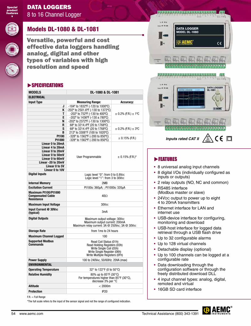
54 www.aemc.com Technical Assistance (800) 343-1391
FEATURES• 8 universal analog input channels• 8 digital I/Os (individually configured as
inputs or outputs)• 2 relay outputs (NO, NC and common)• RS485 interface
(Modbus master or slave)• 24Vdc output to power up to eight
4 to 20mA transmitters• Ethernet interface for LAN and
internet use• USB-device interface for configuring,
monitoring and download• USB-host interface for logged data
retrieval through a USB flash drive• Up to 32 configurable alarms• Up to 128 virtual channels• Detachable display (optional)• Up to 100 channels can be logged at a
configurable rate• Data downloading through the
configuration software or through the freely distributed download DLL
• 4 input channel types: analog, digital, remoted and virtual
• 16GB SD card interface
DATA LOGGERS 8 to 16 Channel Logger
Models DL-1080 & DL-1081
Versatile, powerful and cost effective data loggers handling analog, digital and other types of variables with high resolution and speed
Special product features
RS
48 5 C O M PATIB
LE
D
C I N P U TS
D
IG ITA L I /
O
UNIVERSAL
ETHERNET
PR
O
GRAMMABLE
Inputs rated CAT II IP
Rated20
SPECIFICATIONSMODELS DL-1080 & DL-1081ELECTRICALInput Type Measuring Range: Accuracy:
J -184º to 1832ºF (-120 to 1000ºC)
± 0.2% (F.R.) ± 1ºCK -202º to 2501.6ºF (-130 to 1372ºC)T -202º to 752ºF (-130 to 400ºC)E -202º to 1436ºF (-130 a 780ºC)N -202º to 2372ºF (-130 to 1300ºC)R 68º to 3214.4ºF (20 to 1768ºC)
± 0.2% (F.R.) ± 3ºCS 68º to 3214.4ºF (20 to 1768ºC)B 212º to 3308°F (100 to 1820ºC)
Pt100 -328º to 1562ºF (-200 to 850ºC) ± 0.15% (F.R.)Pt1000 -328º to 1562ºF (-200 to 850ºC)Linear 0 to 20mA
User Programmable ± 0.15% (F.R.)*
Linear 4 to 20mALinear 0 to 20mVLinear 0 to 50mVLinear 0 to 60mV
Linear -20 to 20mVLinear 0 to 5V
Linear 0 to 10VDigital Inputs Logic level “0”: from 0 to 0.8Vdc
Logic level “1”: from 3 to 30Vdc
Internal Memory 2MBExcitation Current Pt100s: 360µA; ; Pt1000s: 320µA
Maximum Pt100/Pt1000 Compensated Cable Resistance
40Ω
Maximum Input Voltage 30Vdc
Input Current @ 30Vdc (typical) 3mA
Digital Outputs Maximum output voltage: 30Vdc Maximum output current: 200mA
Maximum relay current: 3A @ 250Vac; 3A @ 30Vdc
Storage Rate from 1ms to 24 hours
Maximum Channel Logged 100
Supported Modbus Commands
Read Coil Status (01h) Read Holding Registers (03h)
Write Single Coil (05h) Write Single Register (06h)
Write Multiple Registers (0Fh)
Power Supply 100 to 240Vac, 50/60Hz. 20VA (max)ENVIRONMENTALOperating Temperature 32° to 122°F (0 to 50°C)
Relative Humidity 80% up to 85°F (30°C) For temperatures higher than 85°F (30°C),
decrease 3% per °C
Altitude < 2000m
Protection IP20
F.R. = Full Range
*The full scale refers to the input of the sensor signal and not the range of configured indication.

Technical Assistance (800) 343-1391 www.aemc.com 55
CATALOG NO. DESCRIPTION
2134.61 Data Logger Model DL-1080 (8 Analog to 8 Digital Channel, no LCD)
2134.62 Data Logger Model DL-1081 (8 Analog to 8 Digital Channel, LCD)
PRODUCT INCLUDESDL-1080 & DL-1081 software
User manual and drivers also available on USB stick
Model DL-1081
Color Functional Displays
"FAVORITES" Screen
"CONFIGURATION" Screen
"CHART" Screen Software Screens
"ALARMS" Screen
Shows a six-position grid where you can assign a channel to be displayed real-time in each position.
Data logger and display parameters can be changed and viewed on this screen.
Displays a plot of the favorite channels values.
A 32-position grid where each numbered position is related to its equivalent alarm or event. When an alarm is active, its number will be displayed in red on this screen.

56 www.aemc.com Technical Assistance (800) 343-1391
DATA LOGGERS Probe Selection Chart
AEMCMODEL
NUMBER
AEMCCATALOGNUMBER
PROBEOUTPUT
PROBERANGE
MAX RANGEFOR SLII
CABLE DIAMETER
BUS BARSIZE
OUTPUTCONNECTION
USED WITHLOGGERMODEL
NOTES
MN261 2115.82 100mV/Aac
10mV/Aac
0.1 to 24Aac
0.5 to 240Aac
10Aac
100Aac0.78" N/A Lead w/BNC
L101 L102 L562
—
JM830A 2110.83 0.333mA/Aac 1 to 2400A 2400a 2.52" 1.97 x 5.31" Lead L111 —
JM861 2110.9010mV/Aac
1mV/Aac
0.1mV/Aac
1 to 30Aac
1 to 300Aac
1 to 3000Aac
30Aac
300Aac
3000Aac
2.52" 1.97 x 5.31" Lead w/BNCL101 L102 L562
—
MF 300-6-2-10 2126.81 100mV/Aac 10mV/Aac
30Aac
300Aac
10Aac
100Aac1.77" 2.25 x 3/4" Sensor w/BNC
L101 L102 L562
—
300-24-2-1 2112.88 100mV/Aac 10mV/Aac
5 to 30A 5 to 300A
10A 100A 8" N/A Sensor
w/Banana Plugs
L101 L102 L562
Must use adapter # 2118.46
1000-24-1-1 2112.39 1mV/Aac 5 to 1000A 1000A 8" N/A Sensor w/Banana Plugs
L101 L102 L562
Must use adapter # 2118.46
1000-24-2-1 2112.98 10mVac 1mV/Aac
5 to 100A 5 to 1000A
100A 1000A 8" N/A Sensor
w/Banana Plugs
L101 L102 L562
Must use adapter# 2118.46
1000-36-2-1 2113.00 10mVac 1mV/Aac
5 to 100A 5 to 1000A
100A 1000A 11" N/A Sensor
w/Banana Plugs
L101 L102 L562
Must use adapter # 2118.46
3000-24-2-0.3 2114.87 3.3mV/Aac 0.3mV/Aac
5 to 300A 5 to 3000A
300A 3000A 8" N/A Sensor
w/Banana Plugs
L101 L102 L562
Must use adapter # 2118.46
6000-36-2-0.1 2113.21 1mV/Aac 0.1mV/Aac
5 to 600A 5 to 6000A
600A 6000A 11" N/A Sensor
w/Banana Plugs
L101 L102 L562
Must use adapter # 2118.46
30000-24-2-0.1 2113.33 1mV/Aac 0.1mV/Aac
5 to 3000A 5 to 30,000A
1000A 10000A 8" N/A Sensor
w/Banana Plugs
L101 L102 L562
Must use adapter # 2118.46
MN01 2129.17 1mA/Aac 2 to 150A 150A 0.39" N/A Lead L111 —
MN02 2129.20 1mA/Aac
50mA to 100A (1Ω)
50mA to 90A (10Ω)
100Aac 0.39" N/A Lead L111 —
MN03 2129.18 1mV/Aac 2 to 100Aac 100Aac 0.47" N/A Leadw/Banana Plug
L101 L102 L562
Must use adapter # 2118.46
MN93-BK 2140.32 5mV/Aac 2 to 240Aac 200Aac 0.8" N/A Proprietary L104 L564 —
MN193-BK 2140.36 200mV/Aac 10mV/Aac
5 to 100Aac5A
100A 0.8" N/A Proprietary L104 L564 —
MN251 2115.77 1mV/Aac 0.5 to 240A 240Aac 0.78" N/A Leadw/Banana Plug
L101 L102 L562
Must use adapter # 2118.46
MN255 2115.81 100mV/Aac
10mV/Aac
0.1 to 24Aac
0.1 to 240Aac
10Aac
100Aac0.78" N/A Lead
w/Banana Plug
L101 L102 L562
Must use adapter # 2118.46

Technical Assistance (800) 343-1391 www.aemc.com 57
AEMCMODEL
NUMBER
AEMCCATALOGNUMBER
PROBEOUTPUT
PROBERANGE
MAX RANGEFOR SLII
CABLE DIAMETER
BUS BARSIZE
OUTPUTCONNECTION
USED WITHLOGGERMODEL
NOTES
MN313 2116.25 1mA/Aac 0.1 to 200A 200Aac 0.78" 0.79 x 0.2" Lead L111 —
MN353 2116.27 10mV/Aac 0.1 to 150A 100Aac 0.78" N/A Lead w/Banana Plug
L101 L102 L562
Must use adapter # 2118.46
MN373 2116.28 1000mV/Aac
10mV/Aac
0.01 to 2.4Aac
0.1 to 200Aac
1Aac
100Aac0.78" N/A Lead
w/Banana Plug
L101 L102 L562
Must use adapter # 2118.46
MN375 2115.41 100mV/Aac 0.1 to 10A 10Aac 0.78" N/A Lead w/Banana Plug
L101 L102 L562
Must use adapter # 2118.46
MN379 2153.01 200mV/Aac
10mV/Aac
5Aac
100Aac
5Aac
100Aac0.78" N/A Lead
w/Banana Plug
L101 L102 L562
Must use adapter # 2118.46
SR193-BK 2140.33 1mV/Aac 1 to 1200A 1000Aac 2" N/A Proprietary L104 L564 —
SR604 2113.44 1mA/Aac 0.1 to 1000A 1000Aac 2.05" N/A Lead L111 —
SR661 2113.491mV/Aac
10mV/Aac 100mV/Aac
1000Aac
100Aac
10Aac
1000Aac
100Aac
10Aac
2.13" N/A BNCL101 L102 L562
—
SR752 2116.32 1mV/Aac 100mA to 1000A 1000Aac 2.05" 1.96 x 0.19" Lead w/Banana Plug
L101 L102 L562
Must use adapter # 2118.46
SR759 2116.33
1000mV/Aac
100mV/Aac
10mV/Aac
1mV/Aac
1mA to 1Aac
10mA to 10Aac
0.1 to 100Aac
1 to 1000Aac
1Aac
10Aac 100Aac
1000Aac
2.05" 1.96 x 0.19" Lead w/Banana Plug
L101 L102 L562
Must use adapter # 2118.46
DATA LOGGERS Probe Selection Chart

58 www.aemc.com Technical Assistance (800) 343-1391
SPECIFICATIONSMODELS CA811 CA813*Range 20fc, 200fc,
2000fc, 20kfc20fc, 200fc,
2000fc, 20kfc, 200kfc20lux, 200lux,
2000lux, 20k lux20lux, 200lux,
2000lux, 20k lux, 200k lux
Display Resolution 0.01fc or 0.01luxSensor Silicon photodiodeSpectral Response CIE Photoptic CurveAccuracy
2856K Light Source Common Light Source
±5% of Reading ± 10cts ±18% of Reading ± 2cts
±5% of Reading ± 10cts ±11% of Reading ± 2cts
Sample Rate 2.5 times per second, nominal
2.5 times per second, nominal
GENERALDisplay 3½ digit liquid crystal display (LCD), 2000-countOperating Temperature 32° to 122°F (0° to 50°C), <80% RHStorage Temperature -4° to 140°F (-20° to 60°C), 0 to 80% RH without batteryPolarity AutomaticPower Source One 9V Alkaline battery (included)Low Battery Indication is displayed when battery voltage is lowDimensions 6.81 x 2.38 x 1.5" (173 x 60.5 x 38mm)Weight Approx. 7.55 oz (214g)
including batteryApprox. 7.9 oz (224g)
including battery
CATALOG NO. DESCRIPTION
2121.20 Lightmeter Model CA811
2121.21 Lightmeter Model CA813
Features optical sensors that are designed to match the response of the human eye
FEATURES• Easy one-hand operation• Designed to measure a wide range
of lighting types• Removable sensor for remote reading• Measures in footcandles (fc) or lux• Measures incandescent lighting • Cosine corrected• Hold function• Max function (Model CA811)• Peak function (Model CA813)• CIE photoptic (human eye) response• 2000-count backlit LCD• Lightweight and compact• Removable protective sensor cover• Includes rugged, shockproof, protective
and dirt resistant gray holster
APPLICATIONS• Testing for OSHA compliance in
workplace, cleanroom and industrial settings
• Ambient testing for light-sensitive displays and archives in museums and art galleries
Models CA811 & CA813
*Note: Model CA813 offers higher sensitivity (200klux) and has a better spectral response to common light sources. Model CA811 is used to measure incandescent lighting.
ENVIRONMENTAL TESTERSLightmeter
Special product features
C
OR R E C TED
FU N C TI O N
R
E S P O N SE
'' ''
COSINE
CIE
PHOTOPTIC
HOLD

Technical Assistance (800) 343-1391 www.aemc.com 59
CATALOG NO. DESCRIPTION
2121.23 Sound Level Meter Model CA832
SPECIFICATIONSMODEL CA832MEASUREMENTSMeasurement Range 35 to 80dB
50 to 100dB 80 to 130dB
Measurement Rate 2.5 times per secondDynamic Range 50dbFrequency Range 31.5 to 8000HzAccuracy ±1.5dB (ref. 94dB@1kHz)Resolution 0.1dBPrecision ±2.0dBDisplay 2000-countSensor Type 0.5" electric (prepolarized) condenser microphone
True RMS measurement with independent frequency weightingApplicable Standard IEC 651 type 2/ANSI S 1.4 type 2/JIS C 1502Auxiliary Output DC output: 10mV/dB – 50Ω
AC output: 1.0Vrms – 600ΩFrequency Weighting Curves A and CTime Weighting S (slow) and F (fast)
GENERALDisplay 3½ digit liquid crystal display (LCD), 2000-countOperating Temperature 32° to 122°F (0° to 50°C), 80% RH without condensationStorage Temperature -4° to 140°F (-20° to 60°C), 0 to 80% RH without batteryPower Source One 9V Alkaline battery (included)Low Battery Indication is displayed when battery voltage is lowDimensions 9.33 x 2.38 x 1.5" (237 x 60.5 x 38mm)Weight 8.11 oz (230g) including battery
IP
Rated44
FEATURES• Easy one-hand operation• Measures sound according to the
sensitivity of the human ear• Max function• Three measurement ranges from
35 to 130dB• Accuracy ±1.5dB (ref. 94dB@1kHz)• Two time weighting curves:
S (slow) - 550ms and F (fast) - 55ms• Two frequency weighting curves: A and C• Auxiliary output for recording• Tripod mountable• 2000-count backlit LCD• Lightweight and compact• Includes rugged, shockproof,
protective and dirt resistant gray holster
APPLICATIONS• Factories• Schools and Libraries• Airports• Office environments and Studios• Auditoriums• Hospitals
Model CA832
ENVIRONMENTAL TESTERS Sound Level Meter
Tripod mounting screw allows for mounting on a standard tripod stand. (Tripod not included)
PRODUCT INCLUDES
Shockproof holster, protective foam microphone cap, screwdriver, male jack connector, assembly screw for camera type tripod, 9V battery and
user manual.
Designed to assess sound ambiences or nuisances in accordance with
international safety and quality standards
Special product features
FU N C TI O N
R
E C O R DIN
G
M
O U N TA BLE
MAX
TRIPOD
AU
XIL
IARY OUTPU
T

60 www.aemc.com Technical Assistance (800) 343-1391
CATALOG NO. DESCRIPTION
2121.24 Thermo-Hygrometer Model CA846 (NTC)
SPECIFICATIONSMODEL CA846MEASUREMENTS — TEMPERATUREMeasurement Range -4° to 140°F or -20° to 60°C
Display Resolution 0.1°F or 0.1°CSensor NTC Temperature SensorAccuracy -4° to 32°F: ±2°F or -20° to 0°C: ±1°C
32° to 140°F: ±1°F or 0° to 60°C: ±0.5°C
MEASUREMENTS — RELATIVE HUMIDITYMeasurement Range 0 to 100% RHDisplay Resolution 0.1% RHSensor Capacitive Humidity SensorAccuracy ±5.0%, 25°C, 10% to 90% RH
±10.0%, 25°C, 0% to 10% RH, 90% to 100% RH
GENERALDisplay 3½ digit liquid crystal display (LCD), 2000-count
Operating Temperature 32° to 122°F (0° to 50°C), 80% RH
Storage Temperature -4° to 140°F (-20° to 60°C), 0 to 80% RH without battery
Polarity Automatic
Power Source One 9V Alkaline battery (included)
Low Battery Indication is displayed when battery voltage is low
Dimensions 6.81 x 2.38 x 1.5" (173 x 60.5 x 38mm)
Weight Approx. 7 oz (197g) including battery
Provides excellent response time to changes in temperature, good repeatability and accurate readings
Model CA846
FEATURES• Easy one-hand operation
• Measures temperature in °F and °C
• Accurate NTC sensor
• Quick response RH sensor
• Max and Hold functions
• 2000-count backlit LCD
• Lightweight and compact
• Removable protective sensor cover
• Includes rugged, shockproof, protective and dirt resistant gray holster
APPLICATIONS• Greenhouses
• HVAC installation and maintenance
• Office environments
• Labs
• Environmental studies
• Weather monitoring
• Food distribution and storage
• Blood banks
Discover how to maintain an
appropriate humidity level
Características especiales
ENVIRONMENTAL TESTERS Thermo-Hygrometer
Special product features
NTC S E N S O
R
HU
M
ID IT Y S E N
SO
R
F
U N C T I O NS
''''
ACCURATE
M
AX & HOLD
C
APACITIVE

Technical Assistance (800) 343-1391 www.aemc.com 61
CATALOG NO. DESCRIPTION
2121.27 Thermometer Model CA863 (Dual K-type Thermocouple)
2121.34 Infrared Thermometer Model CA876 (Laser, var ε, K-type Thermocouple, -4° to 1022°F)
SPECIFICATIONSMODEL CA863MEASUREMENTSInput Dual K-type thermocoupleTemperature Scale Fahrenheit or Celsius user selectableMeasurement Range -58° to 1999°F or -50° to 1300°CDisplay Resolution 1°F or 1°C, 0.1°F or 0.1°CSensor K-type thermocouple dual input (included)Accuracy (Instrument)
-58° to 1999°F: ±0.3% of Rdg ± 2°F -50° to 1000°C: ±0.3% of Rdg ± 1°C
1000° to 1300°C: ±0.5% of Rdg ± 1°CInput Protection 24Vdc or 24VrmsSample Rate 2.5 times per secondInput Connector Accepts two standard miniature K-type thermocouple plugsGENERALDisplay 3½ digit liquid crystal display (LCD), 2000-countOperating Temperature 32° to 122°F (0° to 50°C), 80% RHStorage Temperature -4° to 140°F (-20° to 60°C), 0 to 80% RH without batteryPolarity AutomaticPower Source One 9V Alkaline battery (included)Low Battery Indication is displayed when battery voltage is low
SPECIFICATIONSMODEL CA876MEASUREMENTS — INFRAREDTemperature Range -4° to 1022°F or -20° to 550°CDisplay Resolution 1°F or 1°CAccuracy ±2% of Reading or ± 6°F (3°C)Response Time One secondEmissivity Adjustable 0.10 to 1.00Sensor ThermopileOptical Lens Fresnel LensLaser <0.5mW (670nm)MEASUREMENTS — K TYPETemperature Range -40° to 2000°F or -40° to 1350°CDisplay Resolution 1°F or 1°C or 0.1°F or 0.1°C (Auto)Sensor K-type thermocouple (included)Accuracy -40° to 2000°F: ±0.1% of Reading ± 2°F
-40° to 1350°C: ±0.1% of Reading ± 1°C
GENERALDisplay 3½ digit liquid crystal display (LCD), 2000-countOperating Temperature 32° to 122°F (0° to 50°C), 80% RHStorage Temperature -4° to 140°F (-20° to 60°C), 0 to 80% RH without batteryPolarity AutomaticPower Source One 9V Alkaline battery (included)Low Battery Indication is displayed when battery voltage is low
FEATURES• Easy one-hand operation• Dual K-type thermocouple included• Measures temperature in °F and °C• 0.1° resolution• Max and hold functions• 2000-count backlit LCD• Lightweight and compact• Includes rugged, shockproof,
protective and dirt resistant gray holster
APPLICATIONS• Process control monitoring and
troubleshooting• HVAC installation and maintenance• Chemical processing• Food processing• Mold injecting and HVAC for
temperature rise and fall• Indoor/outdoor differential
temperature measurements• Plastics
FEATURES• Easy one-hand operation• Non-contact infrared sensor• Laser guide for precise aim• Measures temperature in °F and °C• High 1022°F/550°C measurement• Adjustable emissivity 0.1 to 1.00• Auto-Hold function• 2000-count backlit LCD• Lightweight and compact• Removable protective laser cover• Includes rugged, shockproof,
protective and dirt resistant gray holster
APPLICATIONS• Electrical troubleshooting• Food safety and processing• Automotive repair and maintenance• Marine maintenance and repairs• Test faulty motor winding insulation• Test overheated high voltage
transformers• Test terminals on circuit
breaker panels• Perform HVAC energy audits
ENVIRONMENTAL TESTERS Thermometer
Model CA863
Modelo CA876
Offers the ability to easily switch between temperature readings on both
channels (T1 & T2) and differential (DT)
Features a laser guide for precise infrared temperature measurement

62 www.aemc.com Technical Assistance (800) 343-1391
CATALOG NO. DESCRIPTION
2121.37 Infrared Thermometer Model CA879 (-58˚ to 1022˚F)
SPECIFICATIONSMODEL CA879
ELECTRICALMeasuring Range -58° to 1022°F (-50° to 550°C)
Resolution 0.1°F from -58° to 200°F, 1°F beyond this range0.1°C from -50° to 200°C, 1°C beyond this range
Polarity Automatic (minus only)
Accuracy ±1.5% of Reading ±4°F from -4° to +1022°F / ±9°F of -58° to -4°F
±1.5% of Reading ±2°C from -20° to +550°C / ±5°C of -50° to -20°C
Emissivity Preset at 0.95
Spectral Response 6 to 14µm
Response Time 400ms
Laser Target 1mW (670nm type)
Power Source One 9V Alkaline battery included (6LR61 or 6LF22)
MECHANICALDimensions 9.05 x 3.93 x 2.20" (230 x 100 x 56mm)
Weight 290g
ENVIRONMENTALOperating: Temperature Humidity
32° to 122°F (0° to 50°C)10 to 90% RH
Storage: Temperature Humidity
-4° to 140°F (-20° to 60°C) without battery< 80% RH
SAFETYElectromagnetic Compatibility
EN 50081-1 Ed. 1992: EN 55022EN 50082-1 Ed. 1997: EN 55024
Field of Vision Ratio
PRODUCT INCLUDES
Soft carrying case, 9V battery and user manual
Provides precision measurement with its laser target feature
Model CA879
ENVIRONMENTAL TESTERS Infrared Thermometer
FEATURES• Easy one-hand operation
• Non-contact infrared sensor
• Laser guide for precise aim
• 12:1 Field of Vision Ratio
• Measures temperature in °F and °C
• Fixed 0.95 emissivity
• Auto-HOLD function
• 2000-count backlit LCD
APPLICATIONS• Electrical troubleshooting
• Food safety and processing
• Automotive repair and maintenance
• Marine maintenance and repairs
• Test faulty motor winding insulation
• Test overheated high voltage transformers
• Test terminals on circuit breaker panels
• Perform HVAC energy audits
Special product features
INF
R
A R E D S E N
SO
R
G U I D E
E
MIS S IV IT
Y
ε
NON-CONTAC
T
FIXED 0.95
LASER

Technical Assistance (800) 343-1391 www.aemc.com 63
CATALOG NO. DESCRIPTION
2139.20 Clamp-On Meter Model 401 (TRMS, 1000Vac/dc, 1000Aac, Ohms, Continuity, Temperature)
2139.21 Clamp-On Meter Model 403 (TRMS, 1000Vac/dc, 1000Aac/1500Adc, Ohms, Continuity, Temperature)
2139.50 Power Clamp-On Meter Model 405 (TRMS, 1000Vac/dc, 1000Aac/1500Adc, Phase Rotation, Ohms, Continuity, Power, THD)
2139.30 Clamp-On Meter Model 601 (TRMS, 1000Vac/dc, 2000Aac, Ohms, Continuity, Temperature)
2139.31 Clamp-On Meter Model 603 (TRMS, 1000Vac/dc, 2000Aac/3000Adc, Ohms, Continuity, Temperature)
2139.60 Power Clamp-On Meter Model 605 (TRMS, 1000Vac/dc, 2000Aac/3000Adc, Phase Rotation, Ohms, Continuity, Power, THD)
SPECIFICATIONSMODELS 401/601 TRMS 403/603 TRMS 405/605 TRMS
ELECTRICALCurrent AC (rms) 1000/2000A 1000/2000A 1000/2000ACurrent DC – 1500/3000A 1500/3000ACurrent AC+DC – – 1500/3000AVoltage AC (rms) 1000/1000V 1000/1000V 1000/1000VVoltage DC 1000/1000V 1000/1000V 1000/1000VVoltage AC+DC – – 1000/1000VOhms 100/100kΩ 100/100kΩ 100/100kΩContinuity (Buzzer) Yes (< 40Ω) Yes (< 40Ω) Yes (< 40Ω)Diode Test Yes Yes YesTotal Harmonic Distortion – – YesSingle- and 3-Phase Real Power (AC, DC, AC/DC)*
– – 1000/2000kW 3000/6000kW
Single- and 3-Phase Reactive Power (AC, DC, AC/DC)*
– – 1000/2000kvar 3000/6000kvar
Single- and 3-Phase Apparent Power (AC, DC, AC/DC)*
– – 1000/2000kVA 3000/6000kVA
Temperature (int., ext., C°, F°) Yes Yes –Voltage Frequency (Hz) 20kHz 20kHz 20kHzCurrent Frequency (Hz) 2kHz 2kHz 2kHzPower Function (W, var, VA) – – YesPower Factor – – YesTHD-r/THD-f – – YesAdapter (AC/DC) – 0 to 10V –Phase Rotation – – Yes (2 threads)Auto AC/DC Yes (V) Yes (V & A) Yes (V & A)Auto Power OFF Yes Yes YesHold Button Yes Yes YesBacklight Button Yes Yes YesMin/Max Button Yes Yes YesTrue InRush® Function Yes Yes YesRelative Function – Yes YesPeak ± Function – – YesHz Button Yes Yes YesJaw Opening Size (Diameter) 1.89"/2.36" 1.89"/2.36" 1.89"/2.36"
*3-phase measurements assume balanced load
IP
Rated54
Special product features
CLAMP-ON METERS400 & 600 Series General Purpose Meters
Models 401/601, 403/603 & 405/605
Users can be sure of working in a higher degree of safety with
1000V CAT IV rated meters
FEATURES• 1000V CAT IV Rated
• UL 94 VI flame retardant self-extinguishing
• IP54 Rated
• 10,000 count blue electroluminescent backlit display
• Measures up to 1000Vac (1400V peak), 1000Vdc and AC+DC with resolution to 10mV
• Measures up to 2000Aac and 3000Adc (model dependent)
• Measures single- and three-phase power (real, reactive and apparent) up to 3MW with resolution to 1W (model dependent)
• Measures W, VA, var and PF for 1Φ & 3Φ balanced systems (Models 405 & 605)
• Measures frequency to 20kHz with 0.1Hz resolution
• Auto selects AC or DC measurement voltage
• True InRush® current measurement with 1mS capture
• Jaw opening up to 1.89" (400 series) and up to 2.36" (600 series)
• Leads are constructed with a flexible silicone material
Special product features
F
LA
M
E R E TA R D
AN
T
UL 94 VI
TR
UE INRUSH

64 www.aemc.com Technical Assistance (800) 343-1391
CLAMP-ON METERS 500 Series
CATALOG NO. DESCRIPTION
2139.51 Power Clamp-On Meter Model 407 (TRMS, 1000Vac/dc, 1000Aac/1500Adc, Ohms, Continuity, Energy, Harmonics, Power, THD, Recording)
2139.61 Power Clamp-On Meter Model 607 (TRMS, 1000Vac/dc, 2000Aac/3000Adc, Ohms, Continuity, Energy, Harmonics, Power, THD, Recording)
SPECIFICATIONSMODELS 407 TRMS 607 TRMS
ELECTRICALCurrent AC (rms) 1000A 2000ACurrent DC 1500A 3000ACurrent AC+DC 1500A Peak 3000A PeakVoltage AC (rms) 1000V 1000VVoltage DC 1000V 1000VVoltage AC+DC 1000V 1000VOhms 100kΩ 100kΩContinuity (Buzzer) Yes (< 40Ω) Yes (< 40Ω)Total Harmonic Distortion Yes YesIndividual Harmonics (to 25th) Yes YesSingle- and 3-Phase Real Power (AC, DC, AC/DC)*
1000kW 3000kW
2000kW 6000kW
Single- and 3-Phase Reactive Power (AC, DC, AC/DC)*
1000kvar 3000kvar
2000kvar 6000kvar
Single- and 3-Phase Apparent Power (AC, DC, AC/DC)*
1000kVA 3000kVA
2000kVA 6000kVA
Voltage Frequency (Hz) 20kHz 20kHzCurrent Frequency (Hz) 2kHz 2kHzPower Function (W, var, VA) Yes YesPower Factor Yes YesTHD-r/THD-f Yes YesAuto AC/DC Yes (V & A) Yes (V & A)Auto Power OFF Yes YesHold Button Yes YesBacklight Button Yes YesMin/Max Button Yes YesTrue InRush ® Function Yes YesPeak ± Function Yes YesHarmonics Function Yes YesRec (Record) Function Yes YesWireless BT (Bluetooth) Function Yes YesRecord (Recordings) 1000 1000Hz Button Yes YesJaw Opening Size (Diameter) 1.89" 2.36"
*3-phase measurements assume balanced load
IP
Rated54
FEATURES• 1000V CAT IV Rated• UL 94 VI flame retardant self-extinguishing• IP54 Rated• 10,000 count blue electroluminescent backlit display• Measures up to 1000Vac (1400V peak),
1000Vdc and AC+DC with resolution to 10mV• Measures up to 2000Aac and 3000Adc (Model 607) • Measures W, VA, var and PF for 1Φ & 3Φ balanced systems
• Measures single- and three-phase power (real, reactive and apparent) up to 3MW with resolution to 1W
• Measures frequency to 20kHz with 0.1Hz resolution• Auto selects AC or DC measurement• True InRush® current measurement with 1mS capture• Measures harmonics up to the 25th• Records up to 1000 measurements• Bluetooth communication (communicates up to 30 ft)• Includes FREE DataView® software
for download and report generation• Jaw opening up to 1.89" (400 series) and up to 2.36"
(600 series)• Leads are constructed with a flexible
silicone material
CLAMP-ON METERS 400 & 600 Series Bluetooth Edition Power and Harmonic Meters
PRODUCT INCLUDES
Hard carrying case, set of two color-coded, silicone test leads, test probes and alligator clips, Bluetooth USB adapter, four 1.5V AA batteries, safety information sheet, and USB stick supplied with DataView® software and user manual.
Models 407 & 607
Now available with Android™ mobile application
Models 407 & 607
TR
UE INRUSH
CO
M
M U N I C ATION
WIRELESS
Special product features

Technical Assistance (800) 343-1391 www.aemc.com 65
Jaw Opening: 1.1" (28mm) Conductor Size: one 500kcmil cable
SPECIFICATIONSMODELS 500 502 TRMS 503AC Current (Auto-Ranging) 0.05 to 400A 0.05 to 400Arms 0.05 to 400A Resolution 0.1A 0.01A and 0.1A 0.01A and 0.1A Accuracy 50 to 60Hz 60 to 500Hz
±2% of Reading ± 5cts ±2.8% of Reading ± 5cts
±1.9% of Reading ± 5cts ±2.5% of Reading ± 5cts
±1.5% of Reading ± 10cts ±2.5% of Reading ± 10cts
AC Voltage (Auto-Ranging) 0.5 to 600V 0.5 to 600Vrms 0.5 to 600V Resolution 0.1V and 1V 0.1V and 1V 0.1V and 1V Accuracy 50 to 60Hz 60 to 500Hz
±1.0% of Reading ± 5cts ±1.5% of Reading ± 5cts
±1.5% of Reading ± 5cts ±1.5% of Reading ± 5cts
±0.8% of Reading ± 5cts ±1.5% of Reading ± 5cts
Input Impedance 1MΩ 1MΩ 10MΩDC Current (Auto-Ranging) – – 0.10 to 400A Resolution – – 0.01A and 0.1A Accuracy – – ±2.5% of Reading ± 10ctsDC Voltage (Auto-Ranging) – 0.2 to 600V 0.2 to 600V Resolution – 0.1V and 1V 0.1V and 1V Accuracy – ±1% of Reading ± 2cts ±1% of Reading ± 2cts Input Impedance – 1MΩ 10MΩResistance 0.3 to 400Ω 0.2 to 400Ω 0.2 to 400Ω Accuracy ±1.9% of Reading ± 3cts ±1% of Reading ± 2cts ±1% of Reading ± 2cts Max Test Voltage -1.6Vdc 1.5VDC 1.5VDC
Continuity <35Ω <40Ω <40Ω Max Test Voltage 1.5VDC 1.5VDC 1.5VDC
Frequency (Auto-Ranging) CURRENT INPUT Range 20Hz to 4kHz >4kHz to 10kHz
– –
1Hz Resolution 10Hz Resolution
– –
Accuracy – ±0.1% of Reading ± 1ct – Min Input Signal – 2Arms – Input Impedance – 1MΩ – Overload Protection – 600Arms – VOLTAGE INPUT Range 10Hz to 4kHz >4kHz to 40kHz >40kHz to 400kHz
– 1Hz Resolution –– 10Hz Resolution –– 100Hz Resolution –
Accuracy – ±0.1% of Reading ± 1ct – Min Input Signal 4kHz 40kHz 400kHz
– 5Vrms –– 5Vrms –– 5Vrms –
Input Impedance – 1MΩ – Overload Protection – 600Vrms –Power Source Two 1.5V AAA batteries (included)
CATALOG NO. DESCRIPTION
2117.54 Clamp-On Meter Model 500 (AC, 400Aac, 600Vac, Ohms, Continuity)
2117.66 Clamp-On Meter Model 502 (TRMS, 400Aac, 600Vac/dc, Ohms, Continuity)
2117.22 Clamp-On Meter Model 503 (AC/DC, 400Aac/dc, 600Vac/dc, Ohms, Continuity)
PRODUCT INCLUDES
Soft carrying case, set of two test leads, two 1.5V AAA batteries and user manual.
FEATURES• Compact size - fits into
your pocket
• 400Aac or 400Aac/dc current measurements
• 600Vac/dc volts measurements
• TRMS measurements (Model 502)
• Resistance measurements to 400Ω
• Continuity with beeper below 40Ω
• Frequency measurements from V and A (Model 502)
• Hold function to “freeze” readings
• Push-button for easy Adc zeroing (Model 503)
• Large, easy-to-read 4000-count display
• 42-segment analog bargraph
• Includes test leads and soft carrying pouch
CLAMP-ON METERS 500 Series
Models 500, 502 & 503
Small compact size clamp-meter that fits
comfortably in a tool bag
Special product features
UP TO 400A
AC
DIG
ITA L R E A DOU
T
AN
ALOG BARGRA
PH
S IZ E
'' ''
ME
AS U R E MENT

66 www.aemc.com Technical Assistance (800) 343-1391
CATALOG NO. DESCRIPTION
2117.67 Clamp-On Meter Model 511 (AC, 1000Aac, 750Vac/1000Vdc, Ohms, Continuity, Hz)
2117.68 Clamp-On Meter Model 512 (TRMS, 1000Aac, 750Vac/1000Vdc, Ohms, Continuity, Hz)
2117.70 Clamp-On Meter Model 514 (AC/DC, TRMS, 1000Aac/dc, 750Vac/1000Vdc, Ohms, Continuity, Hz)
SPECIFICATIONSMODELS 511 512 TRMS 514 TRMSAC Current (Auto-Ranging) 0.05 to 1000A 0.05 to 1000Arms 0.05 to 1000Arms Resolution 0.01A, 0.1A and 1A 0.01A, 0.1A and 1A 0.01A, 0.1A and 1A Accuracy 50 to 60Hz 60 to 500Hz
1.9% of Reading ± 5cts 1.9% of Reading ± 5cts
1.9% of Reading ± 5cts 1.9% of Reading ± 5cts
1.9% of Reading ± 5cts 2.5% of Reading ± 5cts
AC Voltage (Auto-Ranging) 0.5 to 750V 0.5 to 750Vrms 0.5 to 750Vrms Resolution 0.1V and 1V 0.1V and 1V 0.1V and 1Vrms Accuracy 60 to 500Hz 1.2% of Reading ± 5cts 1.2% of Reading ± 5cts 1.5% of Reading ± 5cts Input Impedance 10MΩ 10MΩ 10MΩDC Current (Auto-Ranging) – – 1A to 1000A Resolution – – 0.01A, 0.1A and 1A Accuracy – – ±2.5% of Reading ± 10ctsDC Voltage (Auto-Ranging) 0.2 to 1000V 0.2 to 1000V 0.2 to 1000V Resolution 0.1V and 1V 0.1V and 1V 0.1V and 1Vrms Accuracy 0.75% of Reading ± 2cts 0.75% of Reading ± 2cts 1% of Reading ± 2cts Input Impedance 10MΩ 10MΩ 10MΩResistance 0.2 to 4000Ω 0.2 to 4000Ω 0.2 to 4000Ω Accuracy 1% of Reading ± 2cts 1% of Reading ± 2cts 1% of Reading ± 2cts Max Test Voltage 3VDC 3VDC 3VDC
Diode Test 0.6mA 0.6mA 1.7mA Open Circuit Voltage 3VDC 3VDC 3VDC
Continuity <40Ω <40Ω <40Ω Max Test Voltage 3VDC 3VDC 3VDC
Frequency (Auto-Ranging) CURRENT INPUT Range 4kHz 10kHz
1Hz Resolution
1Hz Resolution
1Hz Resolution
– – 10Hz Resolution Accuracy 20Hz to 10kHz 0.1% of Reading ± 1ct 0.1% of Reading ± 1ct 0.1% of Reading ± 1ct Min Input Signal 4kHz 10kHz
2Arms 2Arms 2Arms– – 5Arms
VOLTAGE INPUT Range 4kHz 10kHz
1Hz Resolution 1Hz Resolution 1Hz Resolution10Hz Resolution 10Hz Resolution 10Hz Resolution
Accuracy 10Hz to 10kHz 0.1% of Reading ± 1ct 0.1% of Reading ± 1ct 0.1% of Reading ± 1ct Min Input Signal 4kHz 5Vrms 5Vrms 5Vrms 10kHz 5Vrms 5Vrms 10VrmsPower Source 9V Alkaline battery (included)ENVIRONMENTALOperating Temperature 32° to 104°F (0° to 40°C)
< 80% RH, non-condensing32° to 104°F (0° to 40°C)
< 80% RH, non-condensing*-14° to 122°F (-25° to 50°C),
80% RH, non-condensing
FEATURES• Standard size, full
function clamp-on meter
• 1000Aac or 1000Aac/dc current measurements
• 750Vac or 1000Vdc volt measurements
• TRMS measurements (Models 512 & 514)
• Resistance measurements to 4000Ω
• Continuity with beeper below 40Ω
• Frequency measurements from V and A
• Diode test
• 1ms peak function for fast capture of signals
• Hold function to “freeze” readings
• Push-button for easy Adc zeroing
• Large, easy-to-read, 4000-count display
• 42-segment analog bargraph
• Includes test leads, soft carrying pouch and batteries
PRODUCT INCLUDES
Soft carrying case, a pair of test leads, 9V battery and user manual.
Jaw Opening: 1.575" (40mm) Conductor Size: one 750kcmil cable
or two 350kcmil cables
*Note: If Model 514 is to be used below 32°F (0°C), we suggest that the battery be replaced to ensure proper results.
Full ranges and compliance to international safety and quality standards ensure a professional and reliable tool
Models 511, 512 & 514
Características especiales
Special product features
CLAMP-ON METERS 500 Series
D
IODE TEST
ME
AS U R E M E N
TS
V &
A FREQUENC
Y
TO 4 0 0 0Ω
RESISTANCE

Technical Assistance (800) 343-1391 www.aemc.com 67
SPECIFICATIONSMODELS 670 TRMS 675 TRMSELECTRICALAC Current Measuring Range 0.00 to 99.99A 100 to 1000A 0.00 to 99.99A 100 to 1000A Resolution 0.01A 0.1A 0.01A 0.1A Accuracy 1.5% of Reading ± 5cts (50 to 60Hz)
2.0% of Reading ± 5cts (50 to 500Hz) 4.5% of Reading ± 5cts (500Hz to 3kHz)
1.5% of Reading ± 5cts (50 to 60Hz) 2.0% of Reading ± 5cts (50 to 500Hz)
4.5% of Reading ± 5cts (500Hz to 3kHz)DC Current Measuring Range – 0.00 to 99.99A 100.0 to 999.9A 1000 to 1400A Resolution – 0.01A 0.1A 1A Accuracy
– 1.2% of Reading ± 5cts
2.5% of Reading ± 5cts
2.5% of Reading ± 5cts
AC Voltage Measuring Range 0.0 to 999.9V 0.0 to 999.9V Resolution 0.1V 0.1V Accuracy 1.0% of Reading ± 5cts (50 to 60Hz)
1.2% of Reading ± 5cts (50 to 500Hz) 2.5% of Reading ± 5cts (500Hz to 3kHz)
1.0% of Reading ± 5cts (50 to 60Hz) 1.2% of Reading ± 5cts (50 to 500Hz)
2.5% of Reading ± 5cts (500Hz to 3kHz) Input Resistance 1MΩ 1MΩDC Voltage Measuring Range 0.0 to 999.9V 1000 to 1400V 0.0 to 999.9V 1000 to 1400V Resolution 0.1V 1V 0.1V 1V Accuracy 1% of Reading ± 2cts 1% of Reading ± 2cts Input Resistance 1MΩ 1MΩResistance-Ohms (Ω) Measuring Range 0.0 to 999.9Ω 1000 to 9999Ω 0.0 to 999.9Ω 1000 to 9999Ω Resolution 0.1Ω 1Ω 0.1Ω 1Ω Accuracy 1% of Reading ± 3cts, 3.3Vdc (Vmax) 1% of Reading ± 3cts, 3.3Vdc (Vmax)Continuity ( ) Beeper Activation < 35Ω < 35Ω Accuracy 1% of Reading ± 3cts, 3.3Vdc (Vmax) 1% of Reading ± 3cts, 3.3Vdc (Vmax)Frequency (Hz) Function A - Hz V - Hz A - Hz V - Hz Range 1000Hz 10,000Hz 1000Hz 10,000Hz Resolution 0.1Hz 1Hz 0.1Hz 1Hz Accuracy 1.0% of Reading ± 2cts 1.0% of Reading ± 2ctsTemperature (°C/°F) Measuring Range -40 to 999.5°C 1000 to 1200°C -40 to 2192°F -40 to 999.5°C 1000 to 1200°C -40 to 2192°F Resolution 0.5°C 1°C 1°F 0.5°C 1°C 1°FGENERALPower Supply One 9V, NEDA 1604 (6F22) Alkaline battery (included)Battery Life (no buzzer or backlight) 35 hours (no buzzer or backlight) 30 hoursMECHANICALDigital Display 3 ¾ digits LCD dual display (max reading 9999) 3 ¾ digits LCD dual display (max reading 9999)Jaw Opening 1.65" (42mm) 1.58" (40mm)ENVIRONMENTALOperating Temperature
*-14° to 122°F (-25 to 50°C), 80% RH, non-condensing
*-14° to 122°F (-25 to 50°C), 80% RH, non-condensing
CATALOG NO. DESCRIPTION
2117.49 Clamp-On Meter Model 670 (Dual Display, TRMS, AC Amps, AC/DC Volts, Ohms, Continuity, Frequency, & Temperature)
2117.50 Clamp-On Meter Model 675 (Dual Display, TRMS, AC/DC Amps & Volts, Ohms, Continuity, Frequency & Temperature)
R AT I N G
SAFETY
IP
Rated30
FEATURES• Dual display• Standard size, full
function clamp-on meter• 1000Aac/dc current
measurements (DC current on Model 675 only)
• 1400Vdc volt measurements
• TRMS measurements• Resistance
measurement to 10,000Ω• Continuity with beeper
below 35Ω• Frequency
measurements from V and A inputs
• 1ms peak function for fast capture of signals
• Hold function to “freeze” readings
• Designed to measure amps and volts at the same time
• Push-button for easy Adc zeroing
• Large, easy-to-read 9999-count, backlit LCD display
• Includes test leads and soft carrying case
PRODUCT INCLUDES
Soft carrying case, set of test leads (red/black with safety needle tips), K-type thermocouple, one 9V battery and a user manual.
*Note: If the meter is to be used below 32°F (0°C), we suggest that the battery be replaced to ensure proper results.
CLAMP-ON METERS 670 Series
Models 670 & 675
Dual display simultaneously
measures and displays voltage and
current!
Model 675 Jaw Opening: 1.58" (40mm)
Conductor Size: one 750kcmil cable or two 350kcmil cables
Model 670 Jaw Opening: 1.65" (42mm)
Conductor Size: one 750kcmil cable or two 350kcmil cables
Special product features
TRMS V & A
C A P T U R E
1ms PEAK
DUAL DISPLAY
ME
ASUREMENT
ST

68 www.aemc.com Technical Assistance (800) 343-1391
CATALOG NO. DESCRIPTION
7000.02 Clamp-On Meter Model CM605 (100Aac/dc, Low Current)
SPECIFICATIONSMODEL CM605ELECTRICALAC Current
Measurement Ranges 2 Ranges: 10A, 100AAccuracy & Resolution 10A: 2.0% of Reading ± 10cts - 1mA Resolution
80A: 2.0% of Reading ± 10cts - 10mA Resolution> 80A: 3.5% of Reading ± 10cts - 10mA Resolution
Frequency Range 2 Ranges: 50 to 500HzDC Current (positive only)
Measurement Ranges 2 Ranges: 10A, 100AAccuracy & Resolution 10A: 2.5% of Reading ± 10cts - 1mA Resolution
80A: 2.5% of Reading ± 10cts - 10mA Resolution> 80A: 4.5% of Reading ± 10cts - 10mA Resolution
AC VoltsMeasurement Ranges 600VrmsAccuracy & Resolution 1.5% of Reading ± 5cts - 100mV ResolutionFrequency 40 to 500HzInput Impedance 10MΩ, < 50pF
DC Volts (positive only)*Measurement Ranges 600VAccuracy & Resolution 1.0% of Reading ± 2cts - 100mV ResolutionInput Impedance 10MΩ
Resistance (Ohms)Measurement Ranges 10kΩ (9999Ω)Accuracy & Resolution 1.0% of Reading ± 3cts - 1Ω ResolutionTest Voltage < 3.0Vdc
ContinuityMeasurement Ranges Buzzer < 100Ω ± 25ΩResolution 1ΩTest Voltage < 3.0Vdc
Analog OutputOutput 10mV/Aac & Adc through front banana jacksFrequency 0 to 20kHz @ ± 3dbOutput Impedance 3kΩ, < 50pF
Other FunctionsAdc Zero & Relative Function
One touch push button (∆ZERO Button) to Zero Adc, or other readings.Relative function also used in the other ranges to compare two measurements.
HOLD Function Holds A & V measurements when pressed (HOLD button)PEAK Function Captures PEAK (1ms) V or A measurement when activated (PEAK Button)Auto-Ranging “AUTO” displayed on LCDOver Range “OL” displayed on LCD for all measurementsAuto Power OFF Auto Power OFF after approx 10 minute with Over-RideLow Battery Low Battery indication on LCD
MECHANICALMax. Cable Diameter Ø 0.45" (12mm)Max. Jaw Opening Ø 0.60" (15mm)Power Source Two 1.5V AAA (LR03) batteries (included)Dimensions & Weight 7.95 x 2.76 x 1.33" (202 x 70 x 34mm) – 6.5 oz (180g)Safety Standards IEC/EN 61010-1 and 2-032 – 600V CAT II and 300V CAT III – Pollution Degree 2
Class 2 – Double or reinforced insulation, CE mark*For negative measurement, add 2cts to the accuracy
FEATURES• 10,000-count LCD display -
excellent resolution• 100Aac/dc Ammeter with low
10A range (1mA resolution)• Tapered jaws for crowded
wiring areas (Ø.60"- 15mm Jaw opening) (Ø.45"- 12mm Cable diameter)
• 600Vac/dc voltmeter• Analog output in Aac/dc to
data loggers, etc• Auto-ranging & Adc zero
push-button• Data HOLD & PEAK
functions• Relative function to compare
two measurements• Ohm range & continuity test
with beeper• Auto Power OFF and low
battery indicator• IEC/EN 61010 safety rated &
CE mark• 600Vrms overload protection
PRODUCT INCLUDES
Soft carrying case, test leads, two 1.5V AAA batteries and user manual.
CLAMP-ON METERS 100Aac/dc Low Current
For general industrial monitoring and troubleshooting
Model CM605
Special product features
AC & DC
FU N C TI O N
RELATIVE
1mA AC/DC
AN
ALOG OUTPUT
CU
RR
E
N T R E S OLUT
IONR

Technical Assistance (800) 343-1391 www.aemc.com 69
SPECIFICATIONSMODEL AN-1ELECTRICALWorking Voltage 30 to 600VFrequency 45 to 65HzResistance Per Phase 3.9kΩ ± 5%Relay Duty Time Slow position: 500mS / Fast position: 2.3 secondsPower Source 12VDC – Eight 1.5V AA batteries (included)Power Consumption 180mABattery Life Approx. 40 hours of useMECHANICALDimensions 8.7 x 5.4 x 5.9" (220 x 136 x 150mm)Weight 2.9 lbs (1.3kg)Case Fire resistant polycarbonate UL94 VOENVIRONMENTALReference Temperature 73.4° ± 5°F (23° ± 3°C)Operating Temperature 32° to 122°F (0° to 50°C); 10 to 90% RH (non-condensing)Storage Temperature -40° to 158°F (-40° to 70°C); 10 to 90% RH (non-condensing)
CATALOG NO. DESCRIPTION
1971.01 Artificial Neutral Model AN-1Accessories (Optional)2125.52 Leakage Current Probe Model 2620 (4A-1V/A, 400A-1mV/A output)
SPECIFICATIONSMODEL 2620ELECTRICAL
4A Range 400A RangeCurrent Range 500µA to 4A 500mA to 400AOutput Signal 1mV/mA (4V max) 1mV/A (400mV max)Accuracy 500µA to 10mA
3% of Reading ± 1mV
–
10mA to 100mA 0.5% of Reading ± 0.5mV – 100mA to 4A 0.5% of Reading ± 0.5mV – 500mA to 10A – 0.5% of Reading ± 0.5mV 10A to 100A – 0.35% of Reading ± 0.5mV 100A to 400A – 0.35% of Reading ± 1mVPhase Shift 500µA to 10mA
<15°
–
10mA to 100mA <10° – 100mA to 4A – <1° 500mA to 10A – <0.6°Load Impedance 1MΩ min 1MΩ minFrequency Range 48 to 1000Hz 48 to 1000HzMECHANICALDimensions 11.22 x 6.89 x 1.77" (285 x 175 x 45mm)Weight 2.87 lbs (1300g)
FEATURES• Designed
for ungrounded networks - provides intermittent path to ground for leakage current measurements
• Works from 30 to 600Vac
• Red LED phase voltage indicators• Switch selectable ground fault
cycling of 500mS or 2.3 seconds• Buzzer alerts each momentary fault• Battery operated• Double insulated, fire retardant case• Four color-coded 5 ft 1000V rated leads supplied with
alligator clips• Works with Model 2620 and other leakage current probes
FEATURES• Very high sensitivity• Differential or leakage
current from 500μA• Current up to 400A• Two switch-selectable
measurement ranges: 4Aac/400Aac
• Large inside jaw diameter allows use on large or multiple conductors
• Works with single-, dual- and three-phase systems
• Connect directly to DMMs on mV or VAC range
Model AN-1
Modelo 2620
Generates a momentary grounded artificial neutral to allow the
measurement of fault currents on ungrounded three-phase systems
Check for leakage and locate insulation breakdowns on live circuits
LEAKAGE CURRENT METERS AND PROBESArtificial Neutral & Leakage Current Probe
Jaw Opening: 4.4" (112mm)
Conductor Size: 4.4" (112mm)

70 www.aemc.com Technical Assistance (800) 343-1391
SPECIFICATIONSMODEL 565 TRMSmA AC Current (TRMS, Auto-Ranging) 0 to 600mA Resolution 60mA 600mA
0.01mA (10µA) 0.1mA (100µA)
Accuracy 50 to 60Hz 50 to 500Hz 500Hz to 3kHz
1.2% of Reading ± 5cts 2.5% of Reading ± 5cts 3.5% of Reading ± 10cts
AC Current (TRMS, Auto-Ranging) 10 to 100A Resolution 10A 100A
0.001A (1mA) 0.01A (10mA)
Accuracy 50 to 60Hz 50 to 500Hz 500Hz to 3kHz
1.0% of Reading ± 5cts 1.2% of Reading ± 5cts 2.5% of Reading ± 10cts
AC Voltage (TRMS) 0 to 600V Accuracy 50 to 60Hz 50 to 500Hz 500Hz to 3kHz
1.0% of Reading ± 5cts 1.2% of Reading ± 5cts 2.5% of Reading ± 10cts
DC Voltage 0 to 600V Resolution 0.1V Accuracy 1.0% of Reading ± 3ctsResistance 0 to 1kΩ Accuracy 1.0% of Reading ± 3ctsContinuity Buzzer activates <35Ω (0 to 1kΩ)Frequency (Auto-Ranging) Function A-Hz V-Hz Resolution 0 to 100Hz 100Hz to 1kHz
0.1Hz 1Hz
0.1Hz 1Hz
Sensitivity 10mArms min 5Vrms min Accuracy 0.5% of Reading ± 2ctsFilter On (50/60Hz only); Off (Full frequency range)In-Rush Max 100mS sample timePower Source Two 1.5V AAA batteries (included)
CATALOG NO. DESCRIPTION
2117.56 Clamp-On Leakage Current Meter Model 565 (TRMS, 60mA, 600mA, 10A, 100A, 600Vac/dc, Hz, Ohms, Continuity)
PRODUCT INCLUDES
Two color-coded 5 ft test leads, carrying case, batteries and user manual.
Designed to measure low AC currents, which are typically leakage currents in ground conductors
LEAKAGE CURRENT METERS AND PROBES TRMS Clamp-On Leakage Current Meter
Model 565
FEATURES• Check for leakage and locate
insulation breakdowns on live circuits
• Measures leakage current down to 0.1mA with up to 10μA resolution
• Measures current up to 100Arms
• Measures up to 600VAC/DC
• Measures Hz on either V or A inputs
• Measures resistance and continuity
• Hold feature freezes value• Max feature keeps track of
highest measured in-rush value
• Zero button ideal for measuring relative values
• Filter to isolate 50/60Hz fundamental from harmonics
• Compatible with VDE 0404• Backlight display
Jaw Opening: 1.10" (28mm) Conductor Size: 1" (26mm)
LOAD
Special product features
RES O L U TIO
N
V, A & Ω
& C O N TI N UIT
Y
R10µA
ME
AS
URES FREQUE
NC
Y
M
EASURES

Technical Assistance (800) 343-1391 www.aemc.com 71
SPECIFICATIONSMODEL SR759MEASUREMENTSMeasurement Range 1mA to 1Aac
10mA to 10Aac
0.1 to 100Aac
1 to 1000Aac
Output Signal 1000mVAC/Aac (1V @ 1A)100mVAC/AAC (1V @ 10A)10mVAC/AAC (1V @ 100A)1mVAC/AAC (1V @ 1000A)
MECHANICALMaximum Conductor Size 2.05"Ø (52mm)
Maximum Bus Bar Size
One 1.95 x 0.19" (50 x 5mm)
Output Termination 5 ft (1.5m) Lead
SPECIFICATIONSMODELS MN05 MN114MEASUREMENTSMeasurement Range
5ma to 10aac 1a to 100aac
1ma to 10aac
Output Signal 1mVAC/mAAC (100mV @ 100A)
100mVAC/AAC (1V @ 10A)
MECHANICALMaximum Conductor Size 0.39"Ø (10mm) 0.47"Ø (12mm)
Output Termination 5 ft (1.5m) Lead 5 ft (1.5m) LeadSecurity Rating 600V CAT III; CE approved 250V max.; Not CE approved
CATALOG NO. DESCRIPTION
2116.33 AC Current Probe Model SR759 (1/10/100/1000A, mV/A, High Accuracy, Lead)2129.19 AC Current Probe Model MN05 (1mV/mA – 10A max & 1mV/A – 100A max, Lead)
2110.71 AC Current Probe Model MN114 (100mV/A – 10A max, Lead)
IP
Rated40
FEATURES• Measurement range of 1mA to 1200Aac
• Large jaw opening accommodates up to two 500kcmil conductors
• Ergonomic design and easy operation
• Low phase shift for power measurements
• Designed for DMMs, recorders, loggers, oscilloscopes, power and harmonic meters
• Output terminated with 4mm safety shrouded banana plugs on 5 ft (1.5m) leads
• EN 61010, 600V CAT III safety standard
FEATURES• Small, compact and durable AC probes• “Clothes pin” shape makes them ideal for use
in tight areas, such as breaker panels, controller panels or outlets
• Measurements from 5mA to 100Aac (Model MN05)
• Measurements from 1mA to 10Aac (Model MN114)
• Excellent companion to all DMMs• Permits very low AC current measurements
Model SR759
Models MN05 & MN114
Range selectable probe that offers four switch selectable ranges:
1, 10, 100 or 1000A
Provides AC current measuring capabilities to instruments
with mV inputs
LEAKAGE CURRENT METERS AND PROBES AC Current Probes

72 www.aemc.com Technical Assistance (800) 343-1391
SPECIFICATIONSMODELS 5231 5233Display 6000-count backlit display + 61-segment bargraphAcquisition True RMSAuto-Range or Manual YesBandwidth 3kHz (V)/1kHz (A)Best Accuracy 0.2%AC Voltage 6 ranges/60mV to 1000V
Resolution: 0.01mV6 ranges/60mV to 1000V
Resolution: 0.01mVAC LowZ Voltage 4 ranges/60mV to 1000V
Resolution: 0.01mV4 ranges / 60mV to 1000V
Resolution: 0.01mVDC Voltage 6 ranges/600mV to 1000V
Resolution: 0.01mV6 ranges/600mV to 1000V
Resolution: 0.01mVAC Current/DC Current With 1mV/A clamp:
1 range/600A; Resolution: 0.1A
2 ranges/6 to 10A; Resolution: 0.001A
Resistance Measurement 6 ranges / 60MΩ - Resolution: 0.1Ω
Audible Continuity/ Diode Test Yes
Frequency/Duty Cycle – 3 ranges: up to 3kHz/YesCapacitance 6 ranges / 1000µF - Resolution: 0.01nFTemperature (with external K thermocouple)
–1 range: -20° to +760°C/
4° to +1400°F; Resolution: 1°
Non-contact Voltage Detection (NCV) Yes
Display Hold Function YesRelative Mode – YesMin-Max – YesPower Supply 9V Alkaline battery (6LF22)Protection Rating IP54Dimensions 6.1 x 2.9 x 2.17" (155 x 75 x 55mm)Weight .70 lb (320g)Safety Rating 600V CAT IV/1000V CAT III
R AT I N G
SAFETY
CATALOG NO. DESCRIPTION
2125.64 Digital Multimeter Model 5231 (TRMS, 6000-cts, V, AC/DC, Ohm, CT, NCV)
2125.65 Digital Multimeter Model 5233 (TRMS, 6000-cts, V, A, AC/DC, CAP, Ohm, T, NCV)
IP
Rated54
PRODUCT INCLUDES
Soft carrying case, set of two 5 ft color-coded test leads and user manual.
FEATURES• Non-contact detection of network voltage
(NCV Function-AC only)• AC/DC current up to 10A or 600A with a current
clamp giving direct readings (Model 5231)• High sensitivity with a resolution of 0.01mV• Their protection enables them to withstand
overloads up to 8000V• VLowZ function detect the presence of ghost
voltage by placing a burden on the circuit• Multi-position mounting• 2-Off positions
Models 5231 & 5233
Compact and simple, these multimeters with a large backlit display and non-contact voltage detection are exceptional products and a great value for today's market
DIGITAL MULTIMETERS5000 Series
Thermocouple Included with Model 5233
Special product features
NO
N-CONTACT
MEA
SURE AC/DC
PH
ANTOM VOLTAG
E
VOLTAGE
D
ETECTIO
N
VO
LTAGE & CURRENT

Technical Assistance (800) 343-1391 www.aemc.com 73
SPECIFICATIONSMODELS OX7102III OX7104III
INTERFACEScreen Specifications Color 5.7" LCD (115 x 86mm) 320 x 240 – CCFL backlightingDisplay Mode Vectors with interpolationNo. of Traces on Screen Four traces and four references – split screen and
full screen modes (tracing zone 110 x 74)Front Panel Control 32 direct shortcutsScreen Control Touch screen – Windows-like menus and graphic commandsVERTICALVertical Sensitivity 16 ranges from 2.5mV – 200V/div and up to 156μV/div in verticle
zoom mode (12-bit converter) – Accuracy ± 1% of ReadingBandwidth 100MHzChannels Two isolated channels Four isolated channelsAccuracy ±0.1% of ReadingInput Impedance 1MΩ ± 0.5%Max Input Voltage 600Vdc, 600Vrms, 850Vpk (DC + peak AC at 1kHz)
without 10/1 probe 1000Vrms with 10/1 probe derating -20 dB/decade from 100kHz to 100MHz
Vertical Zoom Zoom factor: from 1 to x 100HORIZONTALTime Base Speed 35 ranges from 1ns/div to 200s/divAccuracy ± 0.1% – Roll mode from 100ms to 200s/divHorizontal Zoom x100 maximumDIGITAL MEMORYMax. Sampling Speed 100GS/s in ETS – 2.5GS/s in Single Shot Mode on each channelVertical Resolution 12 bitsMemory Capacity per Channel “TRC” approx. 10kB, “TXT” approx. 20kB
User Memory 2MBOther Modes Envelope mode (Factors from 2 to 64)XY Mode Between two from the four traces – math functions and cursorsOTHER FUNCTIONSAutoset Complete autoset < 3s with recognition of channels,
Frequency >30HzTrigger Mode Automatic Triggered, Single shot, Auto Level 50%FT Analyzer & Math Functions FT, +, –, x, / – Editor of mathematical functions
Cursors Two or three cursors: V and T simultaneous or Phase Resolution 12 bits, display four digits
Power Source Rechargeable 9V 3.8Ah battery (included)Battery Life Four hour operation when fully chargedCommunication Ethernet, RS-232, Web Server
IP
Rated51
HANDHELD OSCILLOSCOPESOXIII Series
FEATURES• 5 complementary tools in a single
instrument: oscilloscope, FFT analyzer, multimeter/wattmeter, harmonic analyzer on voltage/current/power and recorder
• Sampling rate 2.5GS/s in one-shot mode and 100GS/s in ETS mode (repetitive signals)
• 2 or 4 isolated measurement channels (600V CAT III) and up to 8 traces on screen
• 2 or 4 independent TRMS digital multimeters (8000 counts, 200kHz)
• LCD touch screen and Windows-like menus on screen
• Probix “plug & play” input terminals and smart sensors
• Standard “real-time” FFT analysis and calculation functions on channels
• Multi-interface communication connectors: USB, Centronics and Ethernet
• Memory depth of up to 50,000 points per channel (oscilloscope and recorder modes)
• Triggering on measurement thresholds in oscilloscope and multimeter modes
• Adapter for measuring up to 700Vac RMS 1000Vdc in meter mode
• Web Server (FTP server/client) with cursors and automatic measurements
• MiniFlex® sensors, powered by the instrument (sold as accessory)
• Power measurement option included for power measurements
PRODUCT INCLUDESOX7102III & OX7104III Kit
Aluminum carrying case, two red and black 1.5m color-coded leads with needle probe tips, two PROBIX PRHX1 1/10 Probes 250MHz
(600V CAT III), two red and black grip probes, two stylus, two Ethernet cables (one straight/one crossover), two for OX7102 & four for OX7104
PROBIX 4mm banana plug adapters; one US power adapter (115/230V), one 110V US power cord, one NiMH 9.6V battery pack,
SX-METRO software on CD-ROM, Recorder/Harmonic/Power/50K memory option (installed) and user manual on CD-ROM.
Models OX7102III & OX7104III
Rugged, self-contained, handheld oscilloscope
with 100MHz bandwidth33W
ARRANTY
YEAR
Special product features
12 BIT
B
A N D W I DTH
10
0 & 200MHz
2 OR 4
R
ESOLUTIO
N
ISO
LA
TE D C H ANN
EL
S
R

74 www.aemc.com Technical Assistance (800) 343-1391
HANDHELD OSCILLOSCOPES OXIII Series
SPECIFICATIONSMODELS OX7202III OX7204III
INTERFACEScreen Specifications Color 5.7" LCD (115 x 86mm) 320 x 240 – CCFL backlightingDisplay Mode Vectors with interpolationNo. of Traces on Screen
Four traces and four references – split screen and full screen modes (tracing zone 110 x 74)
Front Panel Control 32 direct shortcutsScreen Control Touch screen – Windows-like menus and graphic commandsVERTICALVertical Sensitivity 16 ranges from 2.5mV – 200V/div and up to 156μV/div in verticle
zoom mode (12-bit converter) – Accuracy ± 1% of ReadingBandwidth 200MHzChannels Two isolated channels Four isolated channelsAccuracy ±0.1% of ReadingInput Impedance 1MΩ ± 0.5%Max Input Voltage 600Vdc, 600Vrms, 850Vpk (DC + peak AC at 1kHz) without 10/1
probe, 1000Vrms with 10/1 probe derating -20 dB/decade from 100kHz to 200MHz
Vertical Zoom x5 maximumHORIZONTALTime Base Speed 35 ranges from 1ns/div to 200s/divAccuracy ± 0.1% - Roll mode from 100ms to 200s/divHorizontal Zoom x100 maximumDIGITAL MEMORYMax. Sampling Speed 100GS/s in ETS – 2.5GS/s in Single Shot Mode on each channelVertical Resolution 12 bitsMemory Capacity per Channel “TRC” approx. 10kB, “TXT” approx. 20kB
User Memory 2MBOther Modes Envelope mode (Factors from 2 to 64)XY Mode Between two from the four traces – math functions and cursorsOTHER FUNCTIONSAutoset Complete autoset < 3s with recognition of channels,
Frequency >30HzTrigger Mode Automatic Triggered, Single shot, Auto Level 50%FT Analyzer & Math Functions FT, +, –, x, / – Editor of mathematical functions
Cursors Two or three cursors: V and T simultaneous or Phase Resolution 12 bits, display four digits
Power Source Rechargeable 9V 3.8Ah battery (included)Battery Life Four hour operation when fully chargedCommunication Ethernet, RS-232, Web Server
IP
Rated51
Models OX7202III & OX7204III
Rugged, self-contained, handheld oscilloscope with 200MHz bandwidth
FEATURES• 5 complementary tools in a single
instrument: oscilloscope, FFT analyzer, multimeter/wattmeter, harmonic analyzer on voltage/current/power and recorder
• Sampling rate 2.5GS/s in one-shot mode and 100GS/s in ETS mode (repetitive signals)
• 2 or 4 isolated measurement channels (600V CAT III) and up to 8 traces on screen
• 2 or 4 independent TRMS digital multimeters (8000 counts, 200kHz)
• LCD touch screen and Windows-like menus on screen
• Probix “plug & play” input terminals and smart sensors
• Standard “real-time” FFT analysis and calculation functions on channels
• Multi-interface communication connectors: USB, Centronics and Ethernet
• Memory depth of up to 50,000 points per channel (oscilloscope and recorder modes)
• Triggering on measurement thresholds in oscilloscope and multimeter modes
• Adapter for measuring up to 700Vac RMS 1000Vdc in meter mode
• Web Server (FTP server/client) with cursors and automatic measurements
• MiniFlex® sensors, powered by the instrument (sold as accessory)
• Power measurement option included for power measurements
PRODUCT INCLUDESOX7202III & OX7204III Kit
Aluminum carrying case, two PROBIX PRHX1 1/10 Probes 250MHz (600V CAT III), two red and black 1.5m color-coded leads with needle probe tips, two red and black grip probes, two stylus, two Ethernet cables (one straight/one crossover), two for OX7202 & four for OX7204 PROBIX 4mm banana plug adapters, one US power adapter (115/230V), one 110V US power cord, one NiMH 9.6V battery pack, one 512MB SD memory card, SX-METRO software on CD-ROM, Recorder/Harmonic/Power/50K memory option (installed) and user manual on CD-ROM.
HANDHELD OSCILLOSCOPES OXIII Series
33WARRANT
Y
YEAR12 BIT
B
A N D W I DTH
10
0 & 200MHz
2 OR 4
R
ESOLUTIO
N
ISO
LA
TE D C H ANN
EL
S
R
Special product features

Technical Assistance (800) 343-1391 www.aemc.com 75
HANDHELD OSCILLOSCOPES OXIII Series
CATALOG NO. DESCRIPTION
2124.58 Handheld Oscilloscope Model OX7102III 100MHz (2 x 100MHz, Color, 50k memory, Harmonics, Recorder, Power)
2124.59 Handheld Oscilloscope Model OX7202III 200MHz (2 x 200MHz, Color, 50k memory, Harmonics, Recorder, Power)
2124.67 Handheld Oscilloscope Model OX7104III 100MHz (4 x 100MHz, Color, 50k memory, Harmonics, Recorder, Power)
2124.68 Handheld Oscilloscope Model OX7204III 200MHz (4 x 200MHz, Color, 50k memory, Harmonics, Recorder, Power)
Accessories (Optional)
2124.75 PROBIX PRHX5, 50Ω Adapter
2124.91 AmpFlex® 0.5A to 3kA, 200kHz for use with Oscilloscope OX Series
2124.92 MiniFlex® 0.5A to 300A, 3MHz for use with Oscilloscope OX Series
HANDHELD OSCILLOSCOPES OXIII Series
Models OX7102III, OX7104III, OX7202III & OX7204III
Four Tools in One!
Recorder
Oscilloscope
The OX III Series supports a great variety of sensors (voltage, current, temperature, 0 to 10V, 4 to 20mA, etc) and displays them in their original physical scale and units.
Triggering menu allows selection of type, duration, delay, count and more using touch screen drop-down menu.
Multimeter Analyzer
Automatic recording of the measured values are stored in memory on all active channels allowing review of periods lasting from five minutes to 24 hours.
Harmonic analysis results are displayed in bargraph form.
OPTIONAL ACCESSORIESProbe options for Models OXIII Series Oscilloscopes
AmpFlex® 0.5A to 3kA, 200kHz Catalog #2124.91
MiniFlex® 0.5A to 300A, 3mHz Catalog #2124.92
PROBIX PRHX5 50Ω Adapter Catalog #2124.75
PROBIX 20mA to 20A Current Probe Catalog #2124.77
PROBIX 4 to 20mA Adapter Catalog #2124.99
Visit our storefront for complete list of accessories www.aemc.com/store

76 www.aemc.com Technical Assistance (800) 343-1391
Learn more on how to select a proper
Clamp-On Current Probe for your specific needs
CURRENT MEASUREMENT PROBESSelection for General Purpose & Oscilloscope/BNC Terminated Probes
Note: Product image size not proportionate. Not all models are CE and UL approved; please consult factory.
• Measurement range of 100mA to 1200Aac
• Large jaw opening accommodates up to two 500kcmil conductors
• Ergonomic design and easy operation
• Low phase shift for power measurements
• Available with mA or mV output signals
• Designed for DMMs, recorders, loggers, oscilloscopes, power and harmonic meters
• CE Mark, UL approved
MN200 & MN300 Series AC Current Probes
Flexible Current Probes
MR400 & MR500 Series AC/DC Current Probes
MD Series AC Current Probes
MN100 Series AC Current ProbesMN01 to MN05 Series AC Current Probes
JM Series AC Current Probes
SL Series AC/DC Current Probes
• Small, compact size
• Measurement range of 5mA to 240Aac
• Jaw opening accommodates conductors up to 250kcmil
• Designed for DMMs, loggers, recorders and oscilloscopes
• 40Hz to 10kHz response
• Available with mA or mV output signals
• Available with jack outputs, integral leads with shrouded safety banana plugs or BNC terminated lead
• CE Mark, UL approved
• Models ranging from 30 to 30,000Arms
• Accuracy 1% of Reading
• TRMS measurements when connected to a TRMS instrument
• No core saturation or damage if overloaded
• Overrange LED for measurement circuitry
• CE Mark
• Small, compact and very tough AC probes
• “Clothes pin” shape makes them ideal for use in tight areas, such as breaker panels, controller panels or outlets
• Measurements from 1mA to 150Aac
• Excellent companions to all DMMs Permits very low AC current measurements
• CE Mark
• Small, compact and very tough AC probes
• “Clothes pin” shape makes them ideal for use in tight areas, such as breaker panels, controller panels or outlets
• Measurements from 1mA to 150Aac
• Excellent companions to all DMMs Permits very low AC current measurements
• Current range: up to 3000Aac (continuous cycle for the full temperature range)
• Output: 1mA/A voltage or V/A voltage
• Designed for use on DMMs, power and harmonic meters, recorders of instruments with AC current ranges
• CE Mark
• Low AC and DC measurements
• 50mA to 100A peak
• Unique design for probing in crowded wiring in industrial and automotive environments
• Hall effect sensor technology
• Use with DMMs, voltmeters and other voltage measuring instruments
• CE Mark
R AT I N G
SAFETY
SR Series Current Probes
• 600A Range with mA or mV output
• Unique hook-shaped jaws that enable the user to “pry” into or “hook” onto cables
• Maximum conductor size is 2 x 500kcmil
• Works as a traditional current transformer with ratio of 1000:1
• AC/DC outputs available
• CE Mark
R AT I N G
SAFETY
• Measurement range of 400Aac/600Adc (MR400 Series)
• Measurement range of 1000Aac/1500Adc (MR500 Series)
• Two distinct jaw shapes to be used for hooking or prying around the conductor
• Low phase shift for power measurements
• Designed for DMMs, recorders, oscilloscopes, power and harmonic meters
• CE Mark
• Measures from 0.5 to 3000Arms
• Accuracy 1% of Reading ± from 0.2 to 0.25A
• TRMS measurements when connected to a TRMS instrument
• No core saturation or damage if overloaded
• Low phase shift for power measurements• Measures only AC• High frequency models available
for oscilloscopes• Excellent linearity• CE Mark
• Measures extremely low level DC from 100μA
• Outputs signal proportional to total current (DC + AC)
• Low noise
• Ultra-compact size and non-contact clamp-on convenience
• Simple plug-in operation
• Designed for use with digital multimeters and oscilloscopes
• No range or mode (AC/DC) switching required
• CE Mark
MiniFlex® Series DC/AC MicroProbes

Technical Assistance (800) 343-1391 www.aemc.com 77
CATALOG NO. DESCRIPTION
1201.51 AC/DC Current Probe Model SL261 (10A-100mV/A, 100A-10mV/A, BNC)2115.82 AC Current Probe Model MN261 (24A-100mV/A, 240A-10mV/A, BNC)1200.72 AC Current Probe Model MR461 (60A-10mV/A, 600A-1mV/A, BNC)1200.73 AC Current Probe Model MR561 (150A-10mV/A, 1500-1mV/A, BNC)2113.49 AC Current Probe Model SR661 (10A-100mV/A, 100A-10mV/A, 1000A-1mV/A, BNC)
2110.90 AC Current Probe Model JM861 (30A-10mV/A, 300A-1mV/A, 3000A-0.1mV/A, BNC)
MODELMEASUREMENT RANGE OUTPUT SIGNAL PHASE
SHIFT*
MAXIMUM CONDUCTOR SIZE OUTPUT CONNECTIONAC DC VOLTAGE Ø CABLE BUS BAR
SL261
100mA to 10A 1 to 100A
100mA to 10A 1 to 100A
100mV/Aac/dc 10mV/Aac/dc
<1.5° 0.46" (11.8mm) N/A
Lead w/BNC
UL
MN261
0.1 to 24A 0.5 to 240A – 100mVac/Aac
10mVac/Aac<2.5° 0.78"
(19.8mm) N/ALead
w/BNC UL
MR461
0.2 to 40A 0.5 to 400A
0.4 to 60A 0.5 to 600A
10mV/Aac/dc 1mV/Aac/dc
<1.5°One 1.18" (30mm) Two 0.95" (24mm)
2 x 500kcmil
Two 1.2 x 0.4" (31.5 x 10mm)
Lead w/BNC
MR561
0.2 to 100A 0.5 to 1000A
0.4 to 150A 0.5 to 1500A
10mV/Aac/dc 1mV/Aac/dc
<1.5° One 1.5" (39mm) Two 0.98" (25mm)
One 1.96 x 0.49" (50 x 12.5mm)
Two 1.96 x 0.19" (50 x 5mm)
Lead w/BNC
SR661
0.1 to 12A 0.1 to 120A 1 to 1200A
—100mVac/Aac 10mVac/Aac 1mVac/Aac
<1° 2.05" (52mm)
1.96 x 0.19" (50 x 5mm)
Lead w/BNC
UL
JM861
1 to 30A 1 to 300A 1 to 3000A
—10mVac/Aac 1mVac/Aac
0.1mVac/Aac<1°
2.52" (64mm) 2.52 x 3.94"
(64 x 100mm)
1.97 x 5.31" (50 x 135mm)
Lead w/BNC
*Phase shift indicated at maximum rating. Note: All probes are rated 600V CAT III and CE compliant. Not all models are UL approved; please consult factory.
CURRENT MEASUREMENT PROBES Oscilloscope/BNC Terminated Probes Selection Chart
Oscilloscope & BNC Terminated Probes
Oscilloscope current probes expand oscilloscope applications in industrial or power measurement environments, and are ideal for analysis and
measurement of distorted current waveforms and harmonics

SERIES MODEL RATIOMEASUREMENT RANGE OUTPUT SIGNAL PHASE
SHIFT**
MAXIMUM CONDUCTOR SIZE OUTPUT
CONNECTIONCATALOG
NO. PRICE***AC DC CURRENT VOLTAGE Ø CABLE BUS BAR
MN01 – 2 to 150A – 1mAAC/AAC – N/A 0.39" (12mm) N/A Lead 2129.17
MN02 1000:1 50mA to 100A 50mA to 90A – 1mA/A – N/A 0.39"
(10mm) N/A Lead 2129.20
MN03 – 2 to 100A – – 1mV/A N/A 0.39" (12mm)
N/A
Lead 2129.18
MN05 – 5mAAC to 10AAC 1 to 100AAC
– – 1mVAC/mAAC 1mVAC/AAC
N/A 0.39" (10mm) Lead 2129.19
MN103 – 1mA to 10A 1 to 100A – – 1mVAC/mAAC
1mVAC/AACN/A
0.47" (12mm)
Lead 1031.02
MN106 1000:1 2 to 150A – 1mAAC/AAC – <10° Lead 1031.17
MN114 – 1mA to 10A – – 100mVAC/AAC <8° Lead 2110.71
MN185 1000:1 50mA to 120A – 1mAAC/AAC – <3.5° Jack 100.185
MN213 1000:1 0.5 to 240A – 1mAAC/AAC* – <2.5°
0.78" (19.8mm) N/A
Lead 2115.75
MN251 – 0.5 to 240A – – 1mVAC/AAC <2.5° Lead 2115.77
MN253 – 0.5 to 240A – – 10mVAC/AAC <2.5° Lead 2115.79
MN255 – 0.1 to 24A 0.1 to 240A – – 100mVAC/AAC
10mVAC/AAC<2.5° Lead 2115.81
MN291 – 0.5 to 240A – – 100mVDC/AAC N/A Lead 2115.84
MN307 – 10mA to 12A – – 100mV/AAC <2.5°
0.78" (19.8mm) N/A
Lead 2116.23
MN312 1000:1 0.1 to 200A – 1mAAC/AAC – <2.5° Jack 2116.24
MN313 1000:1 0.1 to 200A – 1mAAC/AAC – <2.5° Lead 2116.25
MN352 – 0.1 to 150A – – 10mV/AAC <2.5° Jack 2116.26
MN353 – 0.1 to 150A – – 10mV/AAC <2.5° Lead 2116.27
MN373 – 0.01 to 2.4A 0.1 to 200A – – 1000mV/AAC
10mV/AAC<3° Lead 2116.28
MN375 – 0.1 to 10A – – 100mV/AAC <1.5° Lead 2115.41
MN379 – 5 to 100A – – 200mV/AAC 10mV/AAC
<1.5° Lead 2153.01
SL206 – 10mA to 1.5A 50mA to 60A
10mA to 2A 50mA to 80A – 1mV/mAAC/DC
10mV/AAC/DC<1° 0.46"
(11.8mm) N/A Lead 1201.45
MD301 1000:1 2 to 500A – – 1mVDC/AAC N/A
1.18" (30mm)
2 x 500kcmil
2.48 x 0.20" (63 x 5mm)
Lead 1201.07
MD304 100:1 1 to 600A – 10mAAC/AAC – <3° Lead 1201.37
MD305 1000:1 1 to 600A – 1mAAC/AAC – <1° Lead 1201.36
*Diode Protection for open secondary (Output) **Phase shift indicated at maximum rating ***Consult factory for list and NIST Calibration prices Note: Models MN103, MN106, MN114 & MN185 are not CE compliant. MN200 & MN300 series probes are UL approved.
78 www.aemc.com Technical Assistance (800) 343-1391
CURRENT MEASUREMENT PROBES General Purpose Probes Selection Chart
General Purpose Probes
The most complete line of current probes offering a variety of output options and terminations for recorders, data loggers, oscilloscopes, DMMs and other instruments

SERIES MODEL RATIOMEASUREMENT RANGE OUTPUT SIGNAL PHASE
SHIFT**
MAXIMUM CONDUCTOR SIZE
OUTPUT CONNECTION
CATALOG NO.
PRICE***
AC DC CURRENT VOLTAGE Ø CABLE BUS BAR
SR600 1000:1 0.1 to 1000A – 1mAAC/AAC – <0.5°
2.05" (52mm)
1.96 x 0.19" (50 x 5mm)
Jack 2113.42
SR601 1000:1 0.1 to 1000A – 1mAAC/AAC* – <0.5° Jack 2113.43
SR604 1000:1 0.1 to 1000A – 1mAAC/AAC* – <0.5° Lead 2113.44
SR632 1000:5 0.1 to 1000A – 5mAAC/AAC* – <1° Lead 2114.79
SR634250:5 500:5 1000:5
1 to 250A 1 to 500A 1 to 1000A
–20mAAC/AAC 10mAAC/AAC 5mAAC/AAC*
– <1° Jack 2113.48
SR651 – 0.1 to 1000A – – 1mVAC/AAC <0.5° Jack 2113.45
SR701 1000:1 1mA to 1000A – 1mAAC/AAC* – <0.5°
2.05" (52mm)
1.96 x 0.19" (50 x 5mm)
Jack 2116.29
SR704 1000:1 1mA to 1000A – 1mAAC/AAC* – <0.5° Lead 2116.30
SR752 – 100mA to 1000A – – 1mVAC/AAC <0.7° Lead 2116.32
SR759 –
1mA to 1A 10mA to 10A 0.1 to 100A 1 to 1000A
– –
1000mVac/Aac 100mVAC/AAC 10mVAC/AAC 1mVAC/AAC
<1° Lead 2116.33
JM810A 2000:2 1 to 2000A – 1mAAC/AAC – <0.5°
2.52" (64mm)
1.97 x 5.31" (50 x 135mm) 2.52 x 3.94"
(64 x 100mm)
Lead 2110.80
JM813 3000:3 1 to 2400A – 1mAAC/AAC – <0.5° Jack 2110.93
JM830A 3000:1 1 to 2400A – .333mAAC/AAC – <0.5° Lead 2110.83
JM850A1000:1 2000:1 3000:1
1 to 1000A 1 to 2000A 1 to 2400A
–1mAAC/AAC .5mAAC/AAC
.333mAAC/AAC– <0.5° Jack 2110.87
JM865A1000:5 2000:5 3000:5
1 to 1000A 1 to 2000A 1 to 2400A
–5mAAC/AAC
2.5mAAC/AAC 1.67mAac/Aac
– <0.5° Jack 2110.88
*Diode Protection for open secondary (Output) **Phase shift indicated at maximum rating ***Consult factory for list and NIST Calibration prices Note: SR series probes are UL approved.
Technical Assistance (800) 343-1391 www.aemc.com 79
Lead with BNC Jack Leads Shrouded Banana Plugs
Insulated 6.5 ft (2m) coaxial cable with insulated BNC connector rated 600Vrms
Two standard safety banana jacks (4mm)
Double/reinforced 5 ft (1.5m) lead with 4mm safety banana plug
Two 4mm safety banana plugs; standard ¾" (19mm) spacing
CURRENT MEASUREMENT PROBES General Purpose Probes Selection Chart
General Purpose Probes
The most complete line of current probes offering a variety of output options and terminations for recorders, data loggers, oscilloscopes,
DMMs and other instruments
OUTPUT TERMINATIONS

80 www.aemc.com Technical Assistance (800) 343-1391
CATALOG NO. DESCRIPTION
2153.30 Digital FlexProbe® Model 400D-6 w/6' Lead (TRMS, 4Aac, 40Aac, 400Aac)
2153.31 Digital FlexProbe® Model 400D-10 w/6' Lead (TRMS, 4Aac, 40Aac, 400Aac)
2153.32 Digital FlexProbe® Model 4000D-14 w/6' Lead (TRMS, 40Aac, 400Aac, 4000Aac)
Accessories (Optional)
5000.44 MultiFix Multi-Position Magnetic Accessory (available on website storefront)
SPECIFICATIONSMODEL 400D
ELECTRICAL
Display Range 4Aac 40Aac 400Aac
Measurement Range 0.020 to 3.999A 4.00 to 39.99A 40.0 to 399.9A
Resolution 1ma 10ma 100ma
Accuracy ±(2% + 10cts) ±(1.5% + 2cts) ±(1.5% + 2cts)
Sensor Diameter 400D-6: Ø 1.77" (45mm) / 400D-10: Ø 2.75" (70mm)
Sensor Length 400D-6: 6" (170mm) / 400D-10: 10" (250mm)
Bandwidth 10Hz to 3kHz
MODEL 4000D
Display Range 40Aac 400Aac 4000Aac
Measurement Range 0.20 to 39.99A 40.0 to 399.9A 400 to 3999A
Resolution 10ma 100ma 1a
Accuracy ±(2% + 10cts) ±(1.5% + 2cts) ±(1.5% + 2cts)
Sensor Diameter Ø 3.94" (100mm)
Sensor Length 14" (350mm)
Bandwidth 10Hz to 3kHz
MECHANICAL
Power Supply 2 x 1.5V AAA / LR3 batteries
Safety IEC 61010, 600V CAT IV
Operating Temperature 32° to 122°F (0° to 50°C)
Weight Approx. 130g
Casing Dimensions 3.94 x 2.36 x 0.79" (100 x 60 x 20mm)
Connection Cable Length 2.62 ft (0.8 m)
FEATURES• Easy access and measurement,
even in confined spaces where access is difficult
• Measurement from 20mAac to 4000A (model dependent)
• Available with 6", 10" and 14" sensor lengths
• Sensor diameter 1.77" to 3.94" (sensor dependent)
• Resolution down to 1mA (model dependent)
• HOLD feature
• Direct reading
• Compact and simple to use
• Flexible current sensor
• True RMS
• Safety rating of 600V CAT IV
Models 400D & 4000D
Provide a welcomed solution when accessing electrical conductors is difficult in tight places
CURRENT MEASUREMENT PROBES Digital FlexProbe®
Model 4000D-14 (14" probe)
Model 400D-10 (10" probe)
Special product features
T
DIRECT
TRUE RMS
FLE
XI
BLE CURREN
T
RE A D I N G
SE N S O R

Technical Assistance (800) 343-1391 www.aemc.com 81
CATALOG NO. DESCRIPTION
2126.83 MiniFlex® Model MF 300-6-2-10-HF
2126.84 MiniFlex® Model MF 300-10-2-10-HF
SPECIFICATIONSMODELS MF 300-6-2-10-HF MF 300-10-2-10-HFELECTRICALRange 30/300ASignal Output 100mV/10mV/AFrequency Range 5 to 1MHz @ -3dbInfluence of Conductor Positioning 1.5% typical, 3% maxInfluence of Conductor Positioning in Sensor Against Handle 4% typical, 6% max
External Conductor Influence 35dB to 40dB on contactPower Source 9V Alkaline battery (6LF22)
MECHANICALSensor Diameter 5mm ØSensor Length 6" (152mm) 10" (250mm)Max Conductor Size 1.77" (45mm) 2.95" (70mm)Connection Cable Length 6.5 ft (2m)Drop Test Per IEC 68-2-32Vibration Per IEC 68-2-6Mechanical Shock Per IEC 68-2-27Weatherproofing IP 50
ENVIRONMENTALOperating Temperature Range 14° to 131°F (-10° to +55°C)Storage Temperature Range -40° to 158°F (-40° to +70°C)Altitude Operating: 0 to 2000m, working voltage derating above;
Non-operating: 0 to 12,000m
SAFETYSafety Rating EN 61010, 1000V CAT III; 600V CAT IV
R AT I N G
SAFETY
FEATURES• Measures from 0.5 to 300Arms
• Accuracy 1% of Reading ± 0.2A
• TRMS measurements when connected to a TRMS instrument
• No core saturation or damage if overloaded
• 9V battery for typical 140 hours continuous operation
• 1MHz frequency response
• Low phase shift for power measurements
• Insensitive to DC, measures only AC component on DC + AC signals
• Excellent linearity
• Lightweight
• Sensor is resistant to oils and aliphatic hydrocarbons
• Perfect accessory for all oscilloscopes
Model MF 300-6-2-10-HF (6" probe)
Model MF 300-10-2-10-HF (10" probe)
CURRENT MEASUREMENT PROBES Flexible Current Probes
High Frequency Oscilloscope Compatible MiniFlex® Probes
A compact AC current measurement device composed of a flexible sensor and an
electronic module designed to measure frequency response up to 1MHz
Special product features
1MHz
M
EASURES
PE
RFECT FOR ALL
B
AN D W I D TH
OSCILLOSCOPE
S
0.5 T O 3 0 0 Arm
s

82 www.aemc.com Technical Assistance (800) 343-1391
CATALOG NO. DESCRIPTION
2126.81 MiniFlex® Model MF 300-6-2-102126.82 MiniFlex® Model MF 3000-10-2-1Accessories (Optional)2119.94 Adapter – BNC (Female) to 4mm Banana (Male)
SPECIFICATIONSMODELS MF 300-6-2-10 MF 3000-10-2-1ELECTRICALRange 30/300A 300/3000ASignal Output 100mV/10mV/A 10mV/1mV/AFrequency Range 10 to 20kHz with current deratingInfluence of Conductor Positioning 1.5% typical, 3% max
Influence of Conductor Positioning in Sensor Against Handle
4% typical, 5% max
External Conductor Influence 35dB to 40dB on contactPower Source 9V Alkaline battery (included)
MECHANICALSensor Diameter 5mm Ø (vs 12.5 for AmpFlex®)Sensor Length 6" (152mm) 10" (250mm)Max Conductor Size 1.77" (45mm) 2.95" (74.9mm)Connection Cable Length 6.5 ft (2m)Drop Test Per IEC 68-2-32Vibration Per IEC 68-2-6Mechanical Shock Per IEC 68-2-27
ENVIRONMENTALOperating Temperature Range 14° to 131°F (10° to +55°C)Storage Temperature Range -40° to 158°F (-40° to +70°C)Altitude Operating: 0 to 2000m, working voltage
derating above; Non-operating: 0 to 12,000m
SAFETYSafety Rating EN 61010, 1000V CAT III; 600V CAT IV; Pollution Degree II
CURRENT MEASUREMENT PROBES Flexible Current Probes
R AT I N G
SAFETY
MiniFlex® Flexible Current Probes for General Use
A flexible sensor equipped with banana or BNC connector and can be connected directly to any multimeter, wattmeter or logger for effective measurements at the standard frequencies
FEATURES• Measures from 0.5 to 3000Arms• Accuracy 1% of Reading ± 0.25A• TRMS measurements when
connected to a TRMS instrument• No core saturation or damage if
overloaded• Overrange LED for measurement
circuitry• 20kHz frequency response• Low phase shift for power
measurements• Insensitive to DC, measures only AC
component on DC + AC signals• Excellent linearity• 9V Alkaline battery, provides typical
150 hours of continuous operation• EN 61010; 1000V CAT III;
600V CAT IV
Model MF 300-6-2-10 (6" probe)Model MF 3000-10-2-1 (10" probe)
Special product features
LOW PHASE
M
EASURES
20kHz
SH
IF T E R R O
R
FR
EQ
UENCY RESP
ON
SE
0.5 T O 3 0 0 0 Arm
s
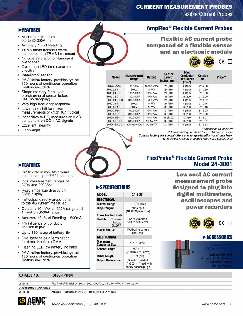
Model Measurement Range Output
Sensor Length
inches (mm*)
Max Conductor Size inches
(mm*)
Catalog No. Price**
300-24-2-10 30/300A 100/10mV/A 24 (610) 8 (190) 2112.881000-24-1-1 1000A 1mV/A 24 (610) 8 (190) 2112.391000-24-2-1 100/1000A 10/1mV/A 24 (610) 8 (190) 2112.981000-36-2-1 100/1000A 10/1mV/A 36 (910) 11 (290) 2113.003000-24-2-0.3 300/3000A 3.3/0.3mV/A 24 (610) 8 (190) 2114.873000-24-1-1 3000A 1mV/A 24 (610) 8 (190) 2112.463000-36-1-1 3000A 1mV/A 36 (910) 11 (290) 2112.483000-24-2-1 300/3000A 10/1mV/A 24 (610) 8 (190) 2113.053000-36-2-1 300/3000A 10/1mV/A 36 (910) 11 (290) 2112.003000-48-2-1 300/3000A 10/1mV/A 48 (1220) 15 (390) 2112.016000-36-2-0.1 600/6000A 1/0.1mV/A 36 (910) 11 (290) 2113.2130000-24-2-0.1 3000/30,000A 1/0.1mV/A 24 (610) 8 (190) 2113.33
*Dimensions rounded off **Consult factory for list and NIST Calibration prices
Consult factory for special offers and ranges/lengths not shown here. Note: Output is safety shrouded 4mm male banana plug
Technical Assistance (800) 343-1391 www.aemc.com 83
SPECIFICATIONSMODEL 24-3001ELECTRICALCurrent Range 300/3000aac
Output Signal mV output (4000mV peak max)
Three Position SlideSwitch 10mV/A 1mV/A ON/OFF
5A to 300Arms 50A to 3000Arms
Power Source 9V Alkaline battery (included)
MECHANICALMaximum Conductor Size 7.6" (193mm)
Sensor Length 24" ± 1" (610mm ± 25.4mm)
Cable Length 6.5 ft (2m)Output Connection Double insulated
14" (355mm) lead with safety banana plugs
CATALOG NO. DESCRIPTION
2120.81 FlexProbe® Model 24-3001 (300/3000Aac, 24", 10mV/A/1mV/A, Lead)Accessories (Optional)2118.46 Adapter – Banana (Female) – BNC (Male) (XM-BB)
FEATURES• Models ranging from
0.5 to 30,000Arms• Accuracy 1% of Reading• TRMS measurements when
connected to a TRMS instrument• No core saturation or damage if
overloaded• Overrange LED for measurement
circuitry• Waterproof sensor• 9V Alkaline battery, provides typical
150 hours of continuous operation (battery included)
• Shape memory for custom pre-shaping of sensor before use (no drooping)
• Very high frequency response• Low phase shift for power
measurements of <1.3°, 0.7° typical• Insensitive to DC, measures only AC
component on DC + AC signals• Excellent linearity• Lightweight
FEATURES• 24" flexible sensor fits around
conductors up to 7.6" in diameter
• Dual measurement ranges of 300A and 3000Aac
• Read amperage directly on DMM display
• mV output directly proportional to the AC current measured
• Output is 10mV/A on 300A range and 1mV/A on 3000A range
• Accuracy of 1% of Reading ± 500mA
• 4% influence of conductor position in jaw
• Up to 150 hours of battery life
• Dual banana plug termination for direct input into DMMs
• Flashing LED low battery indicator
• 9V Alkaline battery, provides typical 150 hours of continuous operation (battery included)
R AT I N G
SAFETY
R AT I N G
SAFETY
ACCESSORIESBanana (female)
BNC (male) (XM-BB)
Catalog #2118.46 (optional for AmpFlex® &
FlexProbe® Flexible Current Probes)
CURRENT MEASUREMENT PROBES Flexible Current Probes
AmpFlex® Flexible Current Probes
FlexProbe® Flexible Current Probe Model 24-3001
Flexible AC current probe composed of a flexible sensor
and an electronic module
Low cost AC current measurement probe
designed to plug into digital multimeters,
oscilloscopes and power recorders
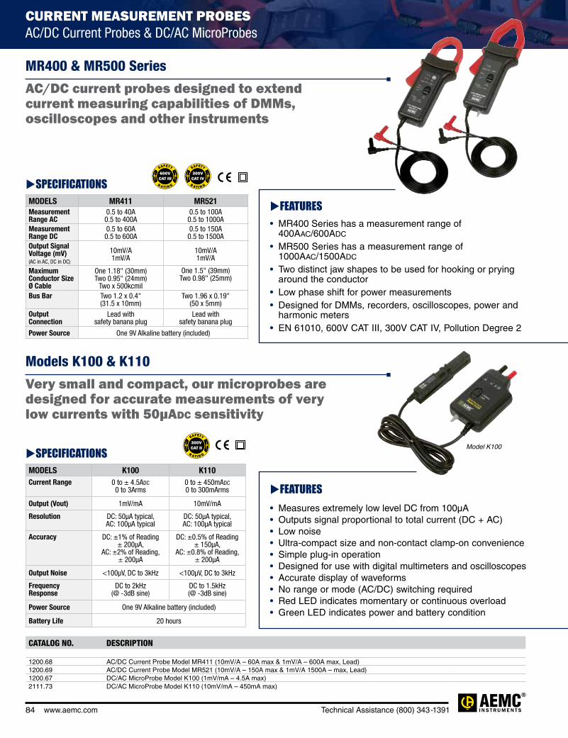
84 www.aemc.com Technical Assistance (800) 343-1391
CATALOG NO. DESCRIPTION
1200.68 AC/DC Current Probe Model MR411 (10mV/A – 60A max & 1mV/A – 600A max, Lead)1200.69 AC/DC Current Probe Model MR521 (10mV/A – 150A max & 1mV/A 1500A – max, Lead)1200.67 DC/AC MicroProbe Model K100 (1mV/mA – 4.5A max)2111.73 DC/AC MicroProbe Model K110 (10mV/mA – 450mA max)
SPECIFICATIONSMODELS MR411 MR521Measurement Range AC
0.5 to 40A 0.5 to 400A
0.5 to 100A 0.5 to 1000A
Measurement Range DC
0.5 to 60A 0.5 to 600A
0.5 to 150A 0.5 to 1500A
Output Signal Voltage (mV) (AC in AC, DC in DC)
10mV/A 1mV/A
10mV/A 1mV/A
Maximum Conductor Size Ø Cable
One 1.18" (30mm) Two 0.95" (24mm)
Two x 500kcmil
One 1.5" (39mm) Two 0.98" (25mm)
Bus Bar Two 1.2 x 0.4" (31.5 x 10mm)
Two 1.96 x 0.19" (50 x 5mm)
Output Connection
Lead with safety banana plug
Lead with safety banana plug
Power Source One 9V Alkaline battery (included)
SPECIFICATIONSMODELS K100 K110Current Range 0 to ± 4.5ADC
0 to 3Arms0 to ± 450mADC 0 to 300mArms
Output (Vout) 1mV/mA 10mV/mA
Resolution DC: 50µA typical, AC: 100µA typical
DC: 50µA typical, AC: 100µA typical
Accuracy DC: ±1% of Reading ± 200µA,
AC: ±2% of Reading, ± 200µA
DC: ±0.5% of Reading ± 150µA,
AC: ±0.8% of Reading, ± 200µA
Output Noise <100µV, DC to 3kHz <100µV, DC to 3kHz
Frequency Response
DC to 2kHz (@ -3dB sine)
DC to 1.5kHz (@ -3dB sine)
Power Source One 9V Alkaline battery (included)
Battery Life 20 hours
FEATURES• MR400 Series has a measurement range of
400AAC/600ADC
• MR500 Series has a measurement range of 1000AAC/1500ADC
• Two distinct jaw shapes to be used for hooking or prying around the conductor
• Low phase shift for power measurements• Designed for DMMs, recorders, oscilloscopes, power and
harmonic meters• EN 61010, 600V CAT III, 300V CAT IV, Pollution Degree 2
FEATURES• Measures extremely low level DC from 100μA• Outputs signal proportional to total current (DC + AC)• Low noise• Ultra-compact size and non-contact clamp-on convenience• Simple plug-in operation• Designed for use with digital multimeters and oscilloscopes• Accurate display of waveforms• No range or mode (AC/DC) switching required• Red LED indicates momentary or continuous overload• Green LED indicates power and battery condition
Model K100
MR400 & MR500 Series
Models K100 & K110
AC/DC current probes designed to extend current measuring capabilities of DMMs, oscilloscopes and other instruments
Very small and compact, our microprobes are designed for accurate measurements of very low currents with 50µAdc sensitivity
CURRENT MEASUREMENT PROBES AC/DC Current Probes & DC/AC MicroProbes

Technical Assistance (800) 343-1391 www.aemc.com 85
SPECIFICATIONSMODELS AX502 AX503Number of Outputs 2 3VOLTAGEOutput 1 & 2 0 to 30VDC 0 to 30VDC
Output 3 (No display) – 2.7 to 5.5VDC
Display Resolution 100mV 100mVBasic Accuracy ±0.5% of Reading ± 1ct ±0.5% of Reading ± 1ctResidual Ripple ±1mVrms ±1mVrmsLINE REGULATION±10% Line Voltage ±0.03% of Reading ± 2mVLOAD REGULATION0 to 2.5A ±0.02% of Reading ± 5mV0 to 5A – ±0.2% Reading ±10mVCURRENTOutput 1 & 2 0 to 2.5A 0 to 2.5AOutput 3 – 5A max (no adjustment)Resolution 10mA 10mABasic Accuracy ±0.5% of Reading ± 1ct ±0.5% of Reading ± 1ctLimit Indicator LED, Outputs 1 and 2 LED, Outputs 1, 2 and 3Short-circuit Protection Electronic current limitation with voltage shutdownOverheating Protection Thermal protectionOUTPUT COUPLINGTracking Output 1: Master/Output 2: Slave Proportional Slave Tracking
(0 to 100% of Master)Series Mode 0 to 60VDC/0 to 2.5AParallel Mode 0 to 30VDC/0 to 5A
CATALOG NO. DESCRIPTION
2130.06 DC Power Supply Model AX502 (Dual outputs, 0 to 2.5A; 0 to 30Vdc)2130.07 DC Power Supply Model AX503 (Triple outputs, two 0 to 2.5A; 0 to 30Vdc; 5A; 2.7 to 5.5Vdc)2131.25 Resistance Decade Box Model BR07 (x1Ω, x10Ω, x100Ω, x1kΩ, x10kΩ, x100kΩ, x1MΩ, 1%)2131.26 Capacitance Decade Box Model BC05 (x0, 1nF, x1nF, x10nF, x100nF, x1knF, 3%)Accessories (Optional)
2117.78 Lead – Set of 3, (2 Color-coded Safety Leads, 1 Ground Lead, 2 Color-coded Alligator Clips and 2 Color-coded Grip Probes) for Power Supply Models AX501-AX503
2131.35 Lead – Replacement, 6 ft. Safety Lead, 4mm Female to Female for use with Decade Boxes
SPECIFICATIONSDECADE 1 2 3 4 5 6 7BR07 1 to 10Ω;
Max current: 700mA
10 to 100Ω; Max current:
200mA
100Ω to 1kΩ; Max current:
70mA
1 to 10kΩ; Max current:
20mA
10 to 100kΩ; Max current:
7mA
100kΩ to 1MΩ;
Max current: 1mA
1 to 10MΩ; Max current:
0.1mA
BC05 0.1 to 1nF 1 to 10nF 10 to 100nF 100nF to 1µF 1 to 10µF – –MODELS BR07 BC05Accuracy 1% 3% (low residual capacitance)Residual Capacitance – 25pF (approx.)
Max Operating Voltage – 300VDC, 230VAC (50Hz)
IP
Rated50
FUENTE DE ALIMENTACIÓN DE CC Y CAJAS DECÁDICAS
FEATURES• Capacitance and resistance
decade boxes• Rotary switch selector• Stop position to prevent
accidental switching from 10 to 0• Male ground (earth) terminal
with safety jack• Outputs on Ø 4mm safety
terminals• Ground jumper lead EN
61010-2-03,150V CAT II, 50V CAT III, Pollution Degree 2
• Resistance ranges are 1Ω to 11.11111MΩ for BR07 and 0.1nF to 11.111μF for BC05
Optional lead set includes two color-coded leads, one ground lead (stripped), two alligator clips and two grip probes.
Catalog #2117.78
FEATURES• Dual 0 to 30Vdc/0 to 2.5A
outputs
• 5.5V/5A output (Model AX503)
• Series and parallel operation permit 0 to 60V or 0 to 5A output
• Low noise (<1mV ripple) and stable linear technology for clean output
• High efficiency toroidal transformers: no fan and low electromagnetic emissions
• Active protection against overloads, short circuits and overheating
• Unique variable tracking mode for master/slave operation: slave or master track proportionally to the original setting
• Simultaneous display of voltage and current
• Highly visible green (V) and red (A) LED displays
• Compact design for bench tops
• Designed to EN 61010-1 safety standards
Models AX502 & AX503
Models BR07 & BC05

86 www.aemc.com Technical Assistance (800) 343-1391
CATALOG NO. DESCRIPTION
2121.10 Phase Rotation Meter Model 66082121.11 Phase & Motor Rotation Meter Model 6609
2121.12 Phase Rotation Meter Model 6610 (Non-contact)
SPECIFICATIONSMODELS 6608 6609 6610
ELECTRICALOperating Voltage 40 to 850Vac
between phasesWith leads connected: 40 to 600Vac between
phases
Static induction
Frequency Range 15 to 400Hz 45 to 65HzPower Supply Self-powered via the
measurement inputs9V Alkaline battery
(included)One 9V Alkaline battery
(included)
MECHANICALDimensions 5.1 x 2.7 x 1.3"
(130 x 69 x 32mm)5.0 x 2.8 x 1.8"
(128 x 72 x 44mm)Weight 4.5 oz (130g) 6 oz (170g) .82 lbs (380g)
battery included
ENVIRONMENTALOperating Temperature 32° to 104°F
(0° to 40°C)
14° to 122°F (-10° to 50°C); max. 80% R.H.
Storage Temperature
-4° to 122°F (-20° to 50°C);
RH < 80%
-4° to 140°F (-20°C to 60°C); max. 80% R.H.
SAFETYSafety Ratings IEC 61010-1, DIN VDE 0411;
IEC 61557-7, DIN VDE 0413-7;Tightness: IP 40 (as per IEC 60529 Ed.92)
EN 61010-1, EN 61326-1
Electrical Safety 600V CAT III 1000V CAT III; 600V CAT IV
R AT I N G
SAFETY
(Model 6610 only) (Models 6608 & 6609 only)
IP
Rated40
PRODUCT INCLUDES
Carrying case, three test leads (4 ft), three alligator clips and a user manual.
Soft carrying case, meter with attached test leads (black, red & blue) with alligator clips, 9V battery and user manual.
FEATURES• Voltage sensing detector clips – no metal
contact points to promote greater safety (Model 6610)
• Indication of live phase presence or phase absence
• Designed for checking a wider range of 3-phase power source from 75V to 1000Vac (Model 6610)
• Determination of a motor's rotation direction (Model 6609)
• Automatic testing as soon as the instrument is connected
• Terminals and cables identified by color-coding to simplify connection (test leads are attached to Model 6610)
• Phase rotation indicators (Model 6608)
• Phase and motor rotation indicators (Models 6609 & 6610)
• Color-coded leads (red, black, blue) and alligator clips (black)
• Color-coded jacks for common U.S. phase colors
• Line supplied - no battery needed (Model 6608)
• Protected internally by high impedance circuit to limit the current to user safe limits
Models 6608, 6609 & 6610
ELECTRICAL TEST TOOLSPhase and Motor Rotation Meters
Ideal for installing rotating machinery or motors, and for checking generator output phase direction
6608 & 6609
6610

Technical Assistance (800) 343-1391 www.aemc.com 87
CATALOG NO. DESCRIPTION
2121.05 AC Line Splitter Model ALS-1
2121.09 Non-Contact AC Voltage Detector Model NC-1
SPECIFICATIONSMODEL NC-1Voltage Sensitivity 120 to 240VAC
Frequency 50/60HzDetection Distance <5mmOver Voltage 600V CAT IIIBattery 2 x 1.5V AAA Alkaline (included)Safety For indoor use and in accordance with over voltage 600V CAT III, Pollution Degree 2
ELECTRICAL TEST TOOLS Tester, Splitter and Detector
FEATURES• Avoids splitting lines -
makes reading current easy
• Increases sensitivity of clamp-on current probes and clamp-on meters ten times in X10 mode
• Direct reading X1 mode
• Voltmeter input jacks
• Integral ground conductor
• Facilitates reading current draw of device plugged into it
• Facilitates reading current draw through extension cords
• 120V, 15A capacity
AC Line Splitter Model ALS-1
Non-Contact AC Voltage Detector Model NC-1
For use with clamp-on meters & multimeters using current probes

88 www.aemc.com Technical Assistance (800) 343-1391
SPECIFICATIONSMODEL 275HVDELECTRICALDetection Frequency 45 to 70Hz
Ranges 240V, 2kV, 6kV, 11kV, 22kV, 33kV, 132kV, 275kV
Detection Selection range is detected at approximately 10" (25cm) from the voltage. Greater detection distances can be
obtained at lower voltage positions
Power Source Three 1.5V C cell batteries (included)MECHANICALSelf Test User selectableIndicators Bright red LED and audible buzzerENVIRONMENTALOperating Temperature 5° to 130°F (-15° to 55°C)Storage Temperature -4° to 150°F (-20° to 65°C)Humidity 0 to 93% RH @ 104°F (40°C)
CATALOG NO. DESCRIPTION
2131.12 Non-Contact High Voltage Detector Model 275HVD (240V to 275kV) Manual self-test
Model 275HVD
Warns the operator of live conductors with the use of its detection sensor
FEATURES• Non-contact high voltage detector
• Wide range of detection; 80V to 275kV; one instrument fits all applications
• Eight switch-selectable voltage sensitivity ranges
• Lightweight, minimizes sway at the end of long hot sticks
• Audible and visual (LED) indication of live voltage
• Self-test ensures that all system functions and indicators are working properly by energizing the complete system
• Designed for use with hot sticks incorporating a shotgun adapter
HIGH VOLTAGE DETECTORSNon-Contact AC High Voltage Detector
PRODUCT INCLUDES
Hard carrying case, three C cell batteries, shotgun adapter and user manual.
Note: Not designed to work on shielded cable or enclosure.
Special product features
R A N G E S
NO
N-CONTACT
8 S
WIT
CH-SELECTAB
LE
AU
DIB
LE & VISUA
L
D
E T E C T OR
INDIC ATIO
N
'' '

Technical Assistance (800) 343-1391 www.aemc.com 89
CATALOG NO. DESCRIPTION
2129.80 Micro-Ohmmeter Model 6240 Accessories (Optional)1017.84 Kelvin Clips 10 ft (10A – Hippo)2118.70 Kelvin Clips 20 ft (10A – Hippo)2118.73 Kelvin Probes 10 ft (1A, Spring Loaded)2118.74 Kelvin Probes 20 ft (1A, Spring Loaded)2118.75 Kelvin Probes Pistol Grip (10A – spring loaded), set of two, 10 ft2118.76 Kelvin Probes Pistol Grip (10A – spring loaded), set of two, 20 ft2118.77 Kelvin Probes (10A – spring loaded), set of two, 10 ft2118.78 Kelvin Probes (10A – spring loaded), set of two, 20 ft2118.79 Kelvin Clips 10 ft (1-10A) Replacement for Cat #2118.712118.80 Kelvin Clips 20 ft (1-10A) Replacement for Cat #2118.72
SPECIFICATIONSMODEL 6240Range 4000µΩ 40mΩ 400mΩ 4000mΩ 40Ω 400ΩAccuracy 0.25% of
Reading ± 2cts
0.25% of Reading ± 2cts
0.25% of Reading ± 2cts
0.25% of Reading ± 2cts
0.25% of Reading ± 2cts
0.25% of Reading ± 2cts
Resolution 1µΩ 10µΩ 0.1mΩ 1mΩ 10mΩ 100mΩTest Current 10A 1A 1A 100mA 10mA 10mAMax. Inductive Load 0 to 5 HMemory Stores up to 99 test resultsPower Source Rechargeable 6V, 8.5Ah NiMH battery pack (included)
ACCESSORIESKelvin clips, set of twoCatalog #1017.84 (included)(10A – Hippo) 10 ftCatalog #2118.70 (optional) (10A – Hippo) 20 ft
Kelvin probes, set of two (optional)Catalog #2118.73 (1A – spring loaded) 10 ft Catalog #2118.74 (1A – spring loaded) 20 ft
Kelvin clips, set of two (optional)Catalog #2118.79(1-10A) 10 ft Catalog #2118.80 (1-10A) 20 ft
Kelvin probes, set of two (optional)Catalog #2118.77 (10A – spring loaded) 10 ftCatalog #2118.78 (10A – spring loaded) 20 ft
Kelvin probes pistol grip, set of two (optional)Catalog #2118.75 (10A – spring loaded) 10 ftCatalog #2118.76 (10A – spring loaded) 20 ft
USB Stick Supplied with DataView® software and user manual
IP
Rated54
cover closed
FEATURES• Reliable low resistance measurements from 5μΩ to 400Ω• Four-terminal Kelvin resistance measurement eliminates
test lead resistance• 10A test current up to 4000μΩ• 0.25% basic accuracy• 1μΩ resolution• Direct reading, easy to operate• Six selectable resistance ranges• Reverse polarity switch• Overload and input fuse protection• Manufactured to international safety and environmental
standards• Automatic decimal point and zeroing• Large terminals accept banana plugs and spaded lugs• Rechargeable NiMH battery with internal charger
(110/220V)• Large multifunctional backlit display • Includes power cord and isolated USB cable • Includes FREE DataView® software for data storage,
real-time display, analysis and report generation
MICRO-OHMMETERS10A Digital
Model 6240
Auto calculates resistance from 5µΩ to 400Ω with resolutions
down to 1µΩ
Special product features
&
Z E R O I N
G
R
1µΩ
AU
TO
DECIMAL PO
INT
RE
VER
SE POLARIT
Y
RES O L U TIO
N
S W IT C H

90 www.aemc.com Technical Assistance (800) 343-1391
CATALOG NO. DESCRIPTION
2129.81 10A Micro-Ohmmeter Model 6250Accessories (Optional)1017.84 Kelvin Clips 10 ft (10A – Hippo)2118.70 Kelvin Clips 20 ft (10A – Hippo)2118.73 Kelvin Probes 10 ft (1A, Spring Loaded)2118.74 Kelvin Probes 20 ft (1A, Spring Loaded)2118.75 Kelvin Probes Pistol Grip (10A – spring loaded), set of two, 10 ft2118.76 Kelvin Probes Pistol Grip (10A – spring loaded), set of two, 20 ft2118.77 Kelvin Probes (10A – spring loaded), set of two, 10 ft2118.78 Kelvin Probes (10A – spring loaded), set of two, 20 ft2118.79 Kelvin Clips 10 ft (1-10A) Replacement for Cat #2118.712118.80 Kelvin Clips 20 ft (1-10A) Replacement for Cat #2118.722119.45 Cable, PC RS-232, DB9 F/F 6 ft Null Modem Cable2129.95 RTD Temperature Probe (plug into faceplate for ambient temperature)2129.96 RTD Temperature Probe with 7 ft extension cable
ACCESSORIESKelvin clips, set of twoCatalog #1017.84 (included)(10A – Hippo) 10 ftCatalog #2118.70 (optional) (10A – Hippo) 20 ft
Kelvin clips, set of two (optional)Catalog #2118.79(1-10A) 10 ft Catalog #2118.80 (1-10A) 20 ft RTD Temperature Probe
(optional)Catalog #2129.95 RTD probe plugs into faceplate
Catalog #2129.96 RTD probe w/7 ft extension cable
Kelvin probes, set of two (optional)Catalog #2118.73 (1A – spring loaded) 10 ft Catalog #2118.74 (1A – spring loaded) 20 ft
Kelvin probes pistol grip, set of two (optional)Catalog #2118.75 (10A – spring loaded) 10 ftCatalog #2118.76 (10A – spring loaded) 20 ft
Kelvin probes, set of two (optional)Catalog #2118.77 (10A – spring loaded) 10 ftCatalog #2118.78 (10A – spring loaded) 20 ft
USB Stick Supplied with DataView® software and user manual
Model 6250
Special product features
FEATURES• Measure from 1µΩ
(0.1μΩ resolution) to 2500.0Ω• Test current selection of 1mA, 10mA,
100mA, 1A and 10A• RTD temperature probe to check
tested sample (optional)• Selectable metal types• Automatic and manual temperature
correction• Two programmable alarm set points• Stores up to 1500 test results• Selectable inductive or resistive
test modes• Automatic multiple test mode (multiple
tests without pressing the test button)• Large multi-line
electroluminescent display• Local or remote test setup and control• Internal rechargeable batteries
conduct up to 5000 – 10A tests• Rugged, double insulated waterproof case• Includes RS-232 to USB 2.0 cable
and AC line cord• Includes FREE DataView® software for
data storage, real-time display, analysis and report generation
Accurate with results within 0.05%
MICRO-OHMMETERS 10A Digital
CO
R R E C TIO
N
''''
0.15%
TEM
PERATURE
STORES
A
C C U R A CY
1500 T E STS
SPECIFICATIONSMODEL 6250
Range 5.0000 mΩ
25.000 mΩ
250.00 mΩ
2500.0 mΩ
25.000 Ω
250.00 Ω
2500.0 Ω
Accuracy 0.15% of Reading +1.0µΩ
0.05% of Reading + 3µΩ
0.05% of Reading + 30µΩ
0.05% of Reading
+ 0.3mΩ
0.05% of Reading + 3mΩ
0.05% of Reading + 30mΩ
0.05% of Reading
+ 300mΩ
Resolution 0.1µΩ 1µΩ 10µΩ 0.1mΩ 1mΩ 10mΩ 100mΩTest Current 10A 10A 10A 1A 100mA 10mA 1mA
Measurement Mode
Selectable: Inductive (continuous test), Resistive (instantaneous test) or Auto (multiple tests)
Metal Type Alpha
Selectable: Copper, Aluminum or Other Metal Programmable from 000.00 to 99.99
Alarms Two – programmable set points from 0.0 to 2500.0Ω
Memory Stores up to 1500 test results; Data in memory can be reviewed on the instrument display, on a PC or via direct printout
Power Source Rechargeable 6V, 8.5Ah NiMH battery pack (included)
Battery Life Approximately 5000 10A tests
IP65
Rated
cover closed
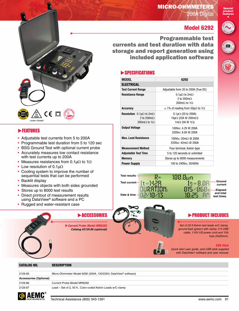
Technical Assistance (800) 343-1391 www.aemc.com 91
CATALOG NO. DESCRIPTION
2129.83 Micro-Ohmmeter Model 6292 (200A, 120/230V, DataView® software)
Accessories (Optional)
2129.86 Current Probe Model MR6292
2129.87 Lead – Set of 2, 50 ft., Color-coded Kelvin Leads w/C-clamp
SPECIFICATIONSMODEL 6292ELECTRICALTest Current Range Adjustable from 20 to 200A (True DC)
Resistance Range 0.1µΩ to 2mΩ2 to 200mΩ
200mΩ to 1Ω
Accuracy ± 1% of reading from 50µΩ to 1Ω
Resolution 0.1µΩ to 2mΩ 2 to 200mΩ 200mΩ to 1Ω
0.1µΩ (20 to 200A)10µΩ (25A @ 200mΩ)
1mΩ (5A @ 1Ω)
Output Voltage 100Vac: 4.2V @ 200A220Vac: 8.6V @ 200A
Max. Load Resistance 100Vac: 20mΩ @ 200A220Vac: 42mΩ @ 200A
Measurement Method Four-terminal, Kelvin-type
Adjustable Test Time 5 to 120 seconds or unlimited
Memory Stores up to 8000 measurements
Power Supply 100 to 240Vac, 50/60Hz
IP
Rated54
cover closed
It I s
Test results
Test current Ground current
Date & time
Elapsed and total
test times
Model 6292
Programmable test currents and test duration with data storage and report generation using
included application software
MICRO-OHMMETERS 200A Digital
FEATURES• Adjustable test currents from 5 to 200A• Programmable test duration from 5 to 120 sec• BSG Ground Test with optional current probe• Accurately measures low contact resistance
with test currents up to 200A• Measures resistances from 0.1μΩ to 1Ω• Low resolution of 0.1μΩ• Cooling system to improve the number of
sequential tests that can be performed• Backlit display• Measures objects with both sides grounded• Stores up to 8000 test results• Direct printout of measurement results
using DataView® software and a PC• Rugged and water-resistant case
PRODUCT INCLUDESACCESSORIES
Set of 20 ft Kelvin test leads w/C clamp, ground lead (green) with clamp, 5 ft USB
cable, 110V US power cord and 15A fuse (5x20mm).
Current Probe Model MR6292 Catalog #2129.86 (optional)
USB Stick Quick start user guide, and USB stick supplied
with DataView® software and user manual.
Special product features
TE
ST CURRENT
S
U
P T O 2 00A
BO
TH
S ID E S G R O UND
ED
MEA
SURES SYSTEMS
ST
ORES TEST RE
SU
LTS I N T E RNA
LLY

92 www.aemc.com Technical Assistance (800) 343-1391
SPECIFICATIONSMODEL 8505ELECTRICALShort <20Ω
Open >20Ω
Transformer >1mh
Capacitor 0.5µf to <1mf
Power Source 4 x 1.5V AA (LR6) Alkaline batteries (included)
Battery Life More than 2500 ten second tests on a full charge
Low Battery Indicator
Red LED blinks; approximately 100 tests can be conducted when LED starts to blink
MECHANICALDimensions 7.2" x 3.65" x 1.26" (182.9 x 92.7 x 32mm) w/o leads
Weight (with battery) 14.4 oz. (408 g)
Case UL94
Vibration IEC 68-2-6 (1.5mm, 10 to 55Hz)
Shock IEC 68-2-6 (1.5mm, 10 to 55Hz)
Drop IEC 68-2-32 (1m)
ENVIRONMENTALOperating Temperature 14° to 122°F (-10° to 50°C)
Storage Temperature -4° to 140°F (-20° to 60°C)
Relative Humidity 0 to 85% @ 95°F (35°C), non-condensing
Altitude 2000m
SAFETYSafety Rating EN61010-1; 50V CAT IV
Environmental IP30
Reference Conditions: 23°C ± 3°C, 30-50% RH, battery voltage: 4.5V ± 10%.
CATALOG NO. DESCRIPTION
2136.51 Quick Tester Model 8505
Quick Tester Model 8505
Designed to check the basic integrity of power transformers and capacitors
TRANSFORMER RATIOMETERSDigital
FEATURES• Checks coil continuity on single- and three-
phase transformers
• Detects open or shorted coils and capacitor
• Detects switch open and closed positions
• Automatically identifies device as a transformer or capacitor
• Single button operation
• Bright LED indicators and buzzer for T and C
• Coiled captive test lead extends to 6 ft each
• Test probe with 5.75" (146mm) shaft ideal for insertion into protective shroud to reach test point
• Multi-frequency source signals improves test reliability and accuracy
• Microprocessor based design for control, stability and repeatability
• Built-in self-test for inductance and capacitance
• Fuse protected
• Battery operated; more than 2500 tests on a full charge
• Low battery indicator begins to blink when capacity of ~100 tests remain
Special product features
CH
EC
KS TRANSFORM
ER
CO
IL CONTINUITY
CH
ECKS CAPACITO
R
FU
NCTIONALITY
BU
ILT-IN SELF-TES
T
C
OMPONENTS
[BIST]
IP
Rated30

Technical Assistance (800) 343-1391 www.aemc.com 93
SPECIFICATIONSMODEL DTR® 8510VT/PT Ratio Range Auto-Ranging 0.8000:1 to 8000:1CT Ratio Range Auto-Ranging 0.8000 to 1000.0Accuracy* Ratio <10 to 1: ±0.2% of Reading
Ratio 0 to 1000 to 1: ±0.1% of Reading Ratio >1000 to 1: ±0.2% of Reading
Ratio 5000 to 8000.0: ±0.25% of ReadingExcitation Signal VT/PT Mode: 32Vrms maximum
CT Mode: 0 to 1A, 0.1 to 4.5Vrms
Excitation Current Display
Range: 0 to 1000mA; Accuracy: ±2% of Reading ± 2mA
Excitation Frequency 70HzMeasurement Method In accordance with
ANSI/IEEE C57.12.90™-2006
Display LCD 16 character, 2 line, large format, LED backlight, day/night visible
Languages Supported English, Spanish, French, Italian, German, Portuguese
Communication Optically isolated USB 2.0Data Storage Stores up to 10,000
complete measurementsPower Source Two rechargeable 12V NiMH batteries
(included)External Charger 90/240V, 50/60Hz (smart charger)Battery Life Up to 10 hours continuous operation;
May not be used while recharging; Low battery LED/LCD indication
Charging Time <4 hours
*23°C ± 5°C, 50 to 70% RH, full battery charge, no external fields or noise.
CATALOG NO. DESCRIPTION
2136.50 Digital Transformer Ratiometer DTR® Model 8510Accessories (Optional)2136.76 Lead-Set of 2, 30 ft for use with DTR® Models 8500 & 8510
2136.77 Lead-Replacement set of 2, 15 ft for use with DTR® Models 8500 & 8510
IP
Rated54
cover closed
TRANSFORMER RATIOMETERS Digital
DTR® Model 8510
PRODUCT INCLUDES
USB Stick Supplied with DataView®
software and user manual.
NiMH batteries (installed), 115V power cord, set of two 15 ft leads, 10 ft USB cable, external battery
charger (90-264Vac, 50/60Hz) and soft carrying case.
Designed for on-site testing of power, potential and current transformers
FEATURES• Measures power transformers, VT/PTs and current
transformer CT turns ratios• Displays turn ratio, excitation current, winding polarity
and % deviation from the nameplate values• Universal voltage (90-240V supply, 50-60Hz)
via external smart/fast battery charger; complete charge in less than 4 hours
• Two internal NiMH batteries provide up to 10 hours of continuous operation
• Tests performed by exciting the primary and reading the secondary; provides safer conditions for the operator
• Display warns of incorrect lead connection, reverse polarity, open and short circuits
• Easy connection and test setup; no calibration or balancing required
• Large dual display with adjustable contrast ensures clearer visibility in any lighting environment day or night
• Low battery indicator• Includes 15 foot lead set and soft carrying bag• Stores up to 10,000 test results in internal memory• USB port facilitates configuring the instrument and
downloading test results• Includes FREE DataView® analysis software for
programming, downloading, storing and report generation of test data
• EN 61010-1; 50V CAT IV
Special product features
M
EASURES
PT
s, V T & C T R
ATI O
S
10 ,0 0 0 T E STS
STORES
PR
ESE
NT DEVIATION
IN
D I C ATIO
N
%

94 www.aemc.com Technical Assistance (800) 343-1391
Portable Test & Measurement instruments for electrical and environmental parameters (Chauvin Arnoux®, Metrix® & Multimetrix® brandnames):
Whatever your application, on site or in the laboratory, the Test & Measurement division can provide professional electricians and electronic engineers with hand-held instruments from the Chauvin Arnoux® and Metrix® brands. Multimetrix® offers an economical product line of clamp-on meters, power supplies and digital multimeters.
Power Measurement & Control instruments for measurement, metering and supervision of electrical networks:
Enerdis® is an acknowledged expert in energy management. Today, Enerdis® is also a key player in the field of electrical network quality analysis and service. Enerdis® service: Quality (ISO 9001:2009/12).
Thermosensors and temperature measurement, control and supervisory instruments:
Pyro-Contrôle® provides temperature measurement, control and calibration solutions for the most demanding process industry requirements, serving industry partners in the chemical, nuclear, metallurgy, glass-making and semiconductor industries. Pyro-Contrôle® has implemented a rigorous (ISO 9001:2009/12) certified Quality Assurance system.
The Chauvin Arnoux Group is a worldwide company organized into activity-based divisions around its traditional areas of expertise
OTHER PRODUCTS FROM CHAUVIN ARNOUX® GROUP
Take a look at Chauvin Arnoux's website for more
product selections

Technical Assistance (800) 343-1391 www.aemc.com 95
SPECIFICATIONSMODEL MTX 162INTERFACEScreen Specifications Color PC screen (min. resolution: 1024 x 768)Display Mode 8 x 10 div.- Multi-windowing
(control panel, trace, zoom, FFT, etc.)Traces on Screen 4 traces + 4 referencesScreen Control Windows-like & online help; All commands available via mouseVERTICALVertical Sensitivity 5mV to 100V/divBandwidth 60MHz (bandwidth limiter: 15MHz, 1.5MHz or 5kHz)Channels 2 channels, class 1, common groundHORIZONTALTime Base Speed 32 ranges from 5ns to 100s/divTRIGGERMode Auto, Triggered, One-shot ROLL, Auto-level at 50%Source CH1, CH2, LineType Rising or falling edge, adjustable pretriggering from 0 to 100%DIGITAL MEMORYMax. Sampling Speed Repetitive = 20GS/s; One-shot = 50MS/sVertical Resolution 8 bitsMemory Capacity Depth = 50,000 points – storage capacity depends on
PC configuration usedCOMMUNICATIONSoftware PC operating software and LabWindows/LabView drivers
(included)SPO (SMART PERSISTENCE OSCILLOSCOPE)Duration of Persistence Analog remanent modeMEASUREMENT PROCESSINGFFT Analyzer/ MATH Functions FFT, +, -, x, /
Manual Cursors dv, dt, 1/dt, phase – cursors linked or unlinked to traceAutomatic Measurements
2 or 19 measurements out of 19 + automatic phase on/any type of curve markers and limits
RECORDER MODEDuration/Sampling Dedicated ROLL mode from 2s to 33min
CATALOG NO. DESCRIPTION
2150.14 PC Scope Module Model MTX 162UE (2-Channel, 60MHz)
2150.15 PC Scope Module Model MTX 162UEW (2-Channel, WiFi, 60MHz)
IP
Rated30
OTHER PRODUCTS FROM CHAUVIN ARNOUX® GROUP PC Oscilloscopes
Model MTX 162
Compact, lightweight and stackable, these instruments can be connected
directly to a PC via USB or Ethernet
Special product features
Real-time trace Typical PC setup screen
FEATURES• 2-channel/60MHz (software only)
• Oscilloscope with FFT and recorder
• Sampling rate 50MS/s in one-shot mode and 20GS/s in ETS mode
• Detects 10ns transients
• 8-bit A/D converter
• Vertical sensitivities of 250μV-100V/div (300V CAT II)
• Advanced trigger modes and SPO (Smart Persistence Oscilloscope) analysis
• Stackable with direct PC connection via USB or Ethernet
• PC operating software (included) and LabWindows/LabView drivers with Windows-like environment (printing, standard files, etc.)
• Local or remote Ethernet universal communication
2 OR 4
CH
AN
N E L M ODE
LS
T
RA N SI E NTS
DETECTS 10ns
STA
CKABLE DIRECT
PC
C O N N E CTION

96 www.aemc.com Technical Assistance (800) 343-1391
SPECIFICATIONSMODELS MTX 1052 / MTX 1054INTERFACEScreen Specifications Color PC screen (min. resolution: 1024 x 768)Display Mode 8 x 10 div.- Multi-windowing (control panel, trace, zoom, FFT, etc.)Traces on Screen 4 traces + 4 referencesScreen Control Windows-like & online help – all commands available via mouseVERTICALVertical Sensitivity 2.5mV – 100V/div, up to 250µV/div with vertical expansionBandwidth 150MHz (bandwidth limiter: 15MHz, 1.5MHz or 5kHz)Channels 2 or 4 channels, class 1, common groundHORIZONTALTime Base Speed 35 ranges from 1ns to 200s/divTRIGGERMode Auto, Triggered, One-shot ROLL, Auto-level at 50%Source CH1, CH2, EXT, Line or CH1 to CH4, LineType Edge, Pulse Width or Delay (40ns to 10.5s),
counting (2 to 16,384 events), TV (525 = NTSC, 625 = PAL/SECAM), Pre-trigger adjustable from 0 to 100%, Hold-off (40ns to 10.5s)
DIGITAL MEMORYMax. Sampling Speed Repetitive = 100GS/s; One-shot = 200MS/sVertical Resolution 10 bits (9 bits used)Memory Capacity Depth = 50,000 points – storage capacity depends
on PC configuration usedCOMMUNICATIONSoftware PC operating software and LabWindows/LabView drivers includedSPO (SMART PERSISTENCE OSCILLOSCOPE)Duration of Persistence 100ms, 200ms, 500ms, 1s, 2s, 5s, 10s and infinite
Performance Acquisition rate 50k waveforms/s/channel, no. of samples acquired: 19MS/s/channel
MEASUREMENT PROCESSINGFFT Analyzer/ MATH Functions
FFT (calculation over 2048 points), + , - , x , / – "Made-to-measure" function editor
Manual Cursors dv, dt, 1/dt, phase – cursors linked or unlinked to traceAutomatic Measurements
2 or 19 measurements out of 19 + automatic phase on any type of curve markers and limits
RECORDER MODEDuration/Sampling Duration: 2s to 31 days / Sampling interval: 40µs to 53.57sHARMONIC ANALYZERAnalysis Range Fundamental from 40Hz to 1kHz + 31 orders on 1 to 4 channelsProcessing Total RMS value, THD and selected order (%F, phase, frequency, Vrms)
CATALOG NO. DESCRIPTION
2150.10 PC Scope Module Model MTX 1052B-PC (2-Channel, 150MHz)2150.11 PC Scope Module Model MTX 1052BW-PC (2-Channel, WiFi, 150MHz)2150.12 PC Scope Module Model MTX 1054B-PC (4-Channel, 150MHz)
2150.13 PC Scope Module Model MTX 1054BW-PC (4-Channel, WiFi, 150MHz)
IP
Rated30
FEATURES• 2- & 4-channel models/150MHz
• Oscilloscope with FFT and recorder
• Harmonic analyzer
• Sampling rate 200MS/s in one-shot mode and 100GS/s in ETS mode
• Detects 10ns transients
• 10-bit A/D converter
• Vertical sensitivities of 250μV-100V/div (300V CAT II)
• Advanced trigger modes and SPO (Smart Persistence Oscilloscope) analysis
• Stackable with direct PC connection via USB or Ethernet
• PC operating software (included) and LabWindows/LabView drivers with Windows-like environment (printing, standard files, etc.)
• Local or remote Ethernet universal communication
Models MTX 1052 & MTX 1054
Browse through Chauvin Arnoux's
Metrix® Test & Measurement Catalog
OTHER PRODUCTS FROM CHAUVIN ARNOUX® GROUP PC Oscilloscopes
Special product features
2 OR 4
CH
AN
N E L M ODE
LS
T
RA N SI E NTS
DETECTS 10ns
STA
CKABLE DIRECT
PC
C O N N E CTION

Technical Assistance (800) 343-1391 www.aemc.com 97
SPECIFICATIONSMODELS OX5022 OX5042INTERFACEDisplay 3.5" color TFT LCD screen; Resolution 320x240 – LED backlightingCommands Direct adjustments on front panel & on-screen menus via browser
(principal & secondary without “hidden menus”)Display Mode 2500 real acquisition points on screenDisplay of Curves on Screen 2 curves + 2 references + memory trace or mathematical calculation
Integrated Interactive Help Function
11 languages: French, English, German, Spanish, Italian, Swedish, Romanian, Russian, Finnish, Polish, Dutch
OSCILLOSCOPE MODEVertical DeflectionBandwidth 20MHz 40MHzBandwidth Limiter 1.5MHz, 5kHzNumber of Channels 2 totally isolated channelsInput Impedance 1MΩ ±0.5%, approx. 17pFMaximum Input Voltage 600V CAT III – Derating -20dB per decade from 100kHz
Vertical Sensitivity 5mV to 200V/divHorizontal DeflectionSweep Speed 25ns/div to 200s/div – Roll Mode from 100ms to 200s/divHorizontal Zoom Zoom factor: x1, x2, x5TriggeringMode Automatic, triggered, one-shot & triggered RollType Edge, pulse width (20ns – 20s)Coupling AC or DC (depending on the coupling of the triggering channel) HF, LF or noise rejectionSensitive ≤ 1.2 divisions p-p up to 20MHz ≤ 1.2 divisions p-p up to 40MHzDigital MemoryMaximum Sampling Rate 2GS/s in ETS mode – 50MS/s in one-shot mode on each channelVertical Resolution 9 bitsMemory Depth 2500 points per channelUser Storage 2MB for storing files: trace (.trc), text (.txt), configuration (.cfg), image files (.bmp)Glitch Mode Duration ≥ 20ns – 1250 min/max pairsDisplay Modes Envelope, Averaging (factors 2 to 64) and XY (vector)Other FunctionsMath Functions Channel inversion, addition, subtraction, multiplication and division (adjustable scaling)Cursor Measurement 2 cursors: V, T, dV, dt simultaneously – 4-digit display resolutionAutomatic Measurement 18 time or level measurements and phase measurementMULTIMETER MODEGeneral Specifications 2 channels, 8000-count display + min/max bargraph
Graphic recording of 2700 measurements (5min to 1 month)Operating Modes Absolute or relative display (absolute, deviation, ref, ref%)
Monitoring (instantaneous, min, max, Avg)AC, DC & AC+DC Voltages
Ranges from 600mV to 600Vrms, 800mV to 800Vdc Accuracy for Vdc 1% reading+20D –50kHz bandwidth
Resistance Range from 80Ω to 32MΩ - accuracy 2% reading + 10D –10ms quick continuity testCapacitance Ranges from 5nF to 5mF – basic accuracy 2% reading + 10DOther Measurements Frequency, rotation speed, 3.3V diode test, temperature measurement
(with K-type thermocouple or infrared probe)POWERMeasurements Single-phase and balanced three-phase active power values (with or without neutral),
simultaneous display of currentHARMONIC ANALYZER MODEMulti-Channel Analysis 2 channels, 31 orders, fundamental frequency from 40 to 450HzSimultaneous Measurements
Total VRMS, THD and selected order (% fundamental, phase, frequency, VrMs)
GENERAL SPECIFICATIONSScreenshots Up to 100 files in standard “.bmp” format, viewable on the instrumentPC Communication Isolated optical USB interface “SX-Metro” PC application software (included)Power Supply 6 LR6 or 6AA NiMh batteries – Battery life up to 8hrs 30min
Universal line adapter isolated from the channels – Quick charging in 2hrs 30minSafety/EMC Safety according to IEC61010-1 Ed3 – 600V CAT III,
EMC according to EN61000-3, 2001 & EN61326-1, 2006
IP
Rated54
The only oscilloscopes, on the market, with isolated channels that fit into one hand
Models OX5022 & OX5042
OTHER PRODUCTS FROM CHAUVIN ARNOUX® GROUP Handscope
Special product features
FEATURES• Two isolated channels
• Three instruments in one
- 20 or 40MHz oscilloscope
- Double 8000-count TRMS multimeter / Power analyzer
- Harmonic analyzer
• 3.5" color LCD screen LED backlighting technology
• Integrated interactive multilingual help function
• 2MB recording data
• Store graphic recordings of 2700 measurements (5min to 1 month)
• Communication via isolated USB SCPI protocol
2
ISOLATED
C
H A N N E LS
D ATA
2MB RECORDIN
G
ST
ORES 2700
ME
AS U R E M ENT
S

98 www.aemc.com Technical Assistance (800) 343-1391
CATALOG NO. DESCRIPTION
2150.20 Handscope Portable Oscilloscope Model OX5022-CK (2-Channel, 20MHz)
2150.21 Handscope Portable Oscilloscope Model OX5042-CK (2-Channel, 40MHz)
Functional Displays
Models OX5022 & OX5042
PRODUCT INCLUDES
“Hands-free” soft carrying case, set of 2 color-coded (red/black) 5 ft silicone leads, set of 2 color-coded (red/black) alligator clips, set of 2 color-coded (red/black) needle tip probes, two 10:1 600V/BNC-M probes, one 100 to 240V power supply (12V output), one US power plug adapter (115/230V), one 4mm banana plug adapter, optical USB cable, six NiMH 1.2V rechargeable batteries, SX-METRO software on CD-ROM, user manual on CD-ROM.
High Performance
Automatically displays measurements for both isolated channels from your choice of 19 measurement types.
Instantly displays measurements in multimeter mode at the press of a button.
Two Independent 8000-count TRMS Digital Multimeters
Storage Communication & PC SoftwareHarmonic Analyzer
Measures two channels of individual harmonic content up to the 31st harmonic.
View real-time measurements on your PC, configure the Handscope, export data to spreadsheet using the SX-Metro included software.
OTHER PRODUCTS FROM CHAUVIN ARNOUX® GROUP Handscope

Technical Assistance (800) 343-1391 www.aemc.com 99
CATALOG NO. DESCRIPTION
2138.02 Function Generator Model GX320 (DDS, 20MHz, USB)
SPECIFICATIONSMODEL GX320INTERFACEDisplay LCD (125 x 45mm) – Adjustable brightness
Display of frequency on 5 digits 20mm highCommands 19 direct-access commands (9 backlit and adjustable)
1 Line Out On/Off key – 1 digital encoder wheelAdjustment of Signal Parameters
Continuous by the encoder, automatic frequency and level ranges, selection of the increment digit (F,P,N…)
BNC Output Terminals TTL, Sweep, Clock and Synch outputsBNC Intput Terminals VCG, Gate, Clock and Synch inputsCONTINUOUS SIGNAL GENERATIONFrequency 0.001Hz to 20.000MHz (11 ranges)Resolution/Accuracy 5-digit display – resolution from 1mHz to 1kHz according to
frequency range, ± 20ppm for F > 10kHz, ± 30ppm for F < 10kHzAmplitude 1mV to 20.0Vpp with open circuit in 3 automatic
ranges – 3-digit Vpp or Vrms displayFlatness ± 1dB up to 20MHz (specs. for level from 0.1Vpp to 20Vpp)Vdc Offset ± 10Vdc with open circuit – accuracy ± 5% ± 5mVWaveforms Sine/Triangle (max frequency 2MHz)/Square & "LOGIC"/TTL outputFREQUENCYModes LIN (linear) or LOG (logarithmic)"INT" internal sweep "Sawtooth" or "Triangle" mode
Unlimited excursion between "F Start" & "F Stop" (256 steps) Sweep time adjustable from 10ms to 100s
"EXT" internal sweep Sweep by signal < 15kHz, amplitude ± 10V VCF IN input impedance 10kΩ approx.
MODULATIONSInternal AM Modulation by a sine signal with a frequency of 1kHz
Modulation rate 20% or 80%External AM Modulation by a signal with a frequency < 15kHzInternal FM Modulation by a sine signal with a frequency of 1kHzExternal FM Modulation by a signal with a frequency < 15kHzFUNCTIONSShift K FSK (Internal/External) = switching between F start & F stop
PSK (Internal/External) = phase switching ± 180°Burst Internal 1 to 65,535 impulsions pulse train period from 10ms to 100s
External 1 to 65,535 impulsions – Synch/Period by a TTL signal with a frequency <200 kHz (VCG IN input)
Gate Validation of the AC component of "Line Out" by a TTL signal with a frequency <2MHz (GATE IN input)
Synch Maximum frequency of signals generated 100kHz Adjustment of phase shift across ± 180° (resolution 1°)
EXTERNAL FREQUENCYMETERMeasurement Range 5Hz to 100MHzAccuracy ± 0.05% + 1 countSafety/Max Acceptable Voltage 300V CAT I/300VrMs
GENERAL SPECIFICATIONSConfiguration Memories Storage/Recall of 15 complete instrument configurationsCommunication Interface "USB A/B" link for the programmable versions and Ethernet interfacePower Supply 115V ±10% or 230V ±10%; 50/60Hz – 20Va max. – Internal selectionSafety/EMC Safety as per IEC 61010-1 (2001) – EMC as per EN 61326-1 (2004)
FEATURES• Frequency range from 20MHz
• DDS technology and frequency accuracy of ±20ppm
• Frequency adjustment stable to the nearest digit
• "LOGIC signal" function for direct adjustment of high and low levels
• LIN or LOG sweep, triangle or sawtooth, with adjustable duration from 10ms to 100s
• Internal and external AM & FM modulation, GATE, BURST, FSK and PSK functions
• Adjustable phase synchronization of several generators in a cascade arrangement
• 100MHz frequency meter, 300V CAT I
• Storage of 15 complete instrument configurations
• Versions programmable via USB link and Ethernet with standard SCPI protocol
OTHER PRODUCTS FROM CHAUVIN ARNOUX® GROUP DDS Generator and Frequency Meter
Model GX320
Cascade arrangement for simulating complex signals with 20MHz and
integrated external frequency meter
Special product features
FR
EQUENCY
FR
O M 2 0 M Hz
& DC O UTPUTS
SIN
E, S
QUARE, TRIANG
LE
STORES 15
CO
N
F IG U R ATION
S

100 www.aemc.com Technical Assistance (800) 343-1391
FEATURES• TRMS measurements• LCI 07: 0010X• Safety rating:
IEC 61010-1: 2001• Agency Approval: IECEx
LC107.0010 X, LCIE 02 ATEX 6005 X, II 2 G D or I M2, Ex ib I, Ex ib IIC T5 or T4 or T3 ,Ex ibD 21 T
• Logic signal measurement and ADP input
• Min/Max/Avg functions• Bargraph with zoom (x5) and
center zero• Rugged design - IP67 rating• Protection by 500mA intrinsic
safety fuse for the current range
• Includes test leads
CATALOG NO. DESCRIPTION
2130.66 Digital Multimeter Model MX 57EX TRMS (IECEx LCIE 07.0010 X, LCIE 02 ATEX 6005 X, Intrinsically Safe, TRMS, 50,000-count, 0.025%)
SPECIFICATIONSMODEL MX 57EX IECEX TRMSAC Current 500μA 5mA 50mA 500mAResolution 10nA 100nA 1µA 10µABandwidth DC to 5kHz DC to 5kHz DC to 5kHz DC to 5kHzAccuracy ±0.75% of
Reading ± 30cts±0.6% of
Reading ± 30cts±0.6% of
Reading ± 30cts±0.7% of
Reading ± 30ctsProtection 600Vrms 600Vrms 600Vrms 600Vrms
AC VoltageResolutionBandwidthAccuracy
Imput ImpedanceProtection
DC Current 500μA 5mA 50mA 500mAResolution 10nA 100nA 1µA 10µAAccuracy ±0.2% of
Reading ± 5cts±0.2% of
Reading ± 2cts±0.05% of
Reading ± 2cts±0.2% of
Reading ± 2ctsProtection 600Vrms 600Vrms 600Vrms 600Vrms
DC VoltageResolutionAccuracy
Imput ImpedanceProtection
ResistanceResolutionAccuracy
Max Open-Circuit VoltageProtection
Continuity 10 to 20ΩResponse Time 1ms
Diode Test 0 to 2VTest Current 1mA ± 20%
Capacitance 50nF to 50mFAccuracy 1% of Reading ± 2cts
Frequency 0.62Hz to 500kHzAccuracy 0.03% of Reading ± 2cts
TemperatureRange (User selectable in °F or °C) -328° to 1472°F (-200° to 800°C)
Sensor PT100/PT1000Digital Display 50,000-countAnalog Bargraph One 9V Alkaline battery (included)Power Source 34-segmentSafety Rating NF EN 50014, EN 50014: 1992; NF EN 50020, EN 50020: 1994Agency Approval Agency Approval: IECEx LC107.0010 X, LCIE 02 ATEX 6005 X,
ExII 2 G D or ExI M2, Ex ib I, Ex ib IIC T5 or T4 or T3, Ex ibD 21 T
*Operating voltages are limited to 60V peak value or currents to 500mA for intrinsically safe operation **User selectable
500mV 5V 50V 500V* 600V*10µV 100µV 1mV 10mV 100mV
40Hz to 1kHz 1kHz to 4kHz 4kHz to 10kHz 10kHz to 30kHz 30kHz to 50kHz±0.3% of
Reading ± 30cts1% of
Reading ± 30cts±2% of
Reading ± 30cts±2% of
Reading ± 30cts±3% of
Reading ± 30cts11MΩ 11MΩ 10MΩ 10MΩ 10MΩ
1100Vpk 1100Vpk 1100Vpk 1100Vpk 1100Vpk
500mV 5V 50V 500V* 600V*10µV 100µV 1mV 10mV 100mV
±0.025% of Reading ± 2cts
±0.025% of Reading ± 2cts
±0.025% of Reading ± 2cts
±0.025% of Reading ± 2cts
±0.2% of Reading ± 2cts
10MΩ/1GΩ** 11MΩ 10MΩ 10MΩ 10MΩ1100Vpk 1100Vpk 1100Vpk 1100Vpk 1100Vpk500Ω 5kΩ 50kΩ 500kΩ 5MΩ 50MΩ10mΩ 100mΩ 1Ω 10Ω 100Ω 1kΩ
±0.07% of Reading ± 5cts
±0.07% of Reading ± 2cts
±0.07% of Reading ± 2cts
±0.07% of Reading ± 2cts
±0.3% of Reading ± 2cts
±1% of Reading ± 2cts
7V
600V
• IECEx• ATEx
IP
Rated67
Model MX 57EX TRMS
An intrinsically safe multimeter for use in dangerous or explosive atmospheres
OTHER PRODUCTS FROM CHAUVIN ARNOUX® GROUP Intrinsically Safe Digital Multimeter
Special product features
TRMS
ME
A
S U R E M ENT
S
INTR
INSICALLY SA
FE
50
,000 COUNT
DIG
ITA L D I SPLAY
T

Technical Assistance (800) 343-1391 www.aemc.com 101
IP
Rated51
CATALOG NO. DESCRIPTION
1748.10 Tachometer Model CA17251748.30 Tachometer Model CA1727
1749.02 Mechanical accessories kit
SPECIFICATIONSMODELS CA1725 & CA1727MEASUREMENTS Rotational Speed Function
Range: 6 to 100,000rpm Resolution: 0.0006 to 6rpm depending on range
Accuracy: 1x10⁻⁴ of Reading ± 6 countsLinear Speed Function
Range: 0.1 to 10,000m/min or ft/min Resolution: 0.0006 to 6m/min depending on range
Accuracy: 1x10⁻⁴ of Reading ± 1 incrementFrequency Function Range: 0.1 to 10,000Hz
Resolution: 0.0004 to 0.4Hz depending on range Accuracy: 4x10⁻⁵ of Reading ± 4 counts
Period Function Range: 0.1 to 10,000msResolution: 0.0003 to 0.3ms depending on range
Accuracy: 1x10⁻⁴ of Reading ± 5 countsDuty Cycle Function Range: 10 to 10,000%
Resolution: 0.1 to 1% depending on range Accuracy: 0.1% of scale from 0.2 to 50Hz
0.2% of scale from 50 to 125Hz / 1% of scale otherwiseCount function Range: 0 to 99,999 events; Accuracy: ± 1 event (Model CA1727)GENERAL Power Source 9V battery Alkaline (included)Battery life 250 x 5 min measurements with optical sensor;
600 x 5 min measurements with external sensorData Storage 4000 measurements (Model CA1727)Dimensions 8.5 X 2.83" (216 x 72 x 47mm)Weight 8.8 oz (250g)Weatherproofing IP51Environment Storage: -4 to +158°F (-20 to +70°C) 95% RH;
Operation: 32 to 131°F (0 to 55°C) 90% RHSENSOR Optical Reflective area: 10 to 90% of the target area.
Measurement distance: 1 to 50cm. The maximum distance is given for a reflective adhesive strip with a minimum area of 10cm2.
Measurement angle: ±15° in relation to the perpendicular of the reflective surface.Mechanical Mechanical adapter: End-fittings: elastomer with a durometer hardness of 80
Pressure on moving part: between 2 and 40N; maximum speed: 10,000rpm Service life: approx. 1000 hours at 3000rpm with a pressure of 20N
Conical end-fitting accessory: Minimum diameter of measurement shaft: 5mmCylindrical end-fitting accessory: Speed measurements on shafts with a diameter
greater than 5mm or flat-ended shaftsEnd-fitting accessory with wheel; Wheel diameter: 30.183mm;
Wheel development: 10cm ± 0.1mm
FEATURES• Measurements up to
100,000rpm
• Multiple functions and automatic routines for data acquisition and storage: measurement of rotational speed, linear speed, count, frequency and period
• Extensive programming possibilities
• Digital display with analog bargraph
• USB interface for processing results on a PC (Model CA1727)
• Includes TachoGraph software on CD-ROM (Model CA1727) download memory only
• Stores up to 4000 measurements results
Models CA1725 & CA1727
Simple to use and offers numerous measurement possibilities with
or without contact
OTHER PRODUCTS FROM CHAUVIN ARNOUX® GROUP Infrared Tachometers
PRODUCT INCLUDES
ACCESSORY
Catalog #1749.02 Mechanical adapter, calibrated wheel, conical
end fitting and cylindrical end fitting
Mechanical Accessories Kit
Special product features
Hard case, FRB Fconnector, 9V battery, a set of 15 reflective strips, quick start guide and user manual. The Model CA1727 also includes a USB cable
and TachoGraph software on CD-ROM.
10,0
00 COUNT
DIG
ITA L D IS PLA
Y
EXT
EN
SIVE PROGRAM
MIN
G
P
O S S I B I L IT IE
S
ME
ASU R E MENT
S
ST
ORES 4000

100.185 AC Current Probe Model MN185 78
1017.84 Kelvin Clips 10 ft (10A – Hippo) 89, 90
1031.02 AC Current Probe Model MN103 78
1031.17 AC Current Probe Model MN106 78
1200.67 DC/AC MicroProbe Model K100 84
1200.68 AC/DC Current Probe Model MR411 84
1200.69 AC/DC Current Probe Model MR521 84
1200.72 AC Current Probe Model MR461 77
1200.73 AC Current Probe Model MR561 77
1201.07 AC Current Probe Model MD301 78
1201.36 AC Current Probe Model MD305 78
1201.37 AC Current Probe Model MD304 78
1201.45 AC Current Probe Model SL206 78
1201.51 AC/DC Current Probe Model SL261 25, 77
1748.10 Tachometer Model CA1725 101
1748.30 Tachometer Model CA1727 101
1749.02 Mechanical accessories kit 101
1971.01 Artificial Neutral Model AN-1 69
2110.71 AC Current Probe Model MN114 71, 78
2110.80 AC Current Probe Model JM810A 79
2110.83 AC Current Probe Model JM830A 56, 79
2110.87 AC Current Probe Model JM850A 79
2110.88 AC Current Probe Model JM865A 79
2110.90 AC Current Probe Model JM861 56, 77
2110.93 AC Current Probe Model JM813 79
2111.73 DC/AC MicroProbe Model K110 84
2112.00 AmpFlex® Flexible Current Probe Model 3000-36-2-1 83
2112.01 AmpFlex® Flexible Current Probe Model 3000-48-2-1 83
2112.39 AmpFlex® Flexible Current Probe Model 1000-24-1-1 56, 83
2112.46 AmpFlex® Flexible Current Probe Model 3000-24-1-1 83
2112.48 AmpFlex® Flexible Current Probe Model 3000-36-1-1 83
2112.88 AmpFlex® Flexible Current Probe Model 300-24-2-1 56, 83
2112.98 AmpFlex® Flexible Current Probe Model 1000-24-2-1 56, 83
2113.00 AmpFlex® Flexible Current Probe Model 1000-36-2-1 56, 83
2113.05 AmpFlex® Flexible Current Probe Model 3000-24-2-1 83
2113.21 AmpFlex® Flexible Current Probe Model 6000-36-2-0.1 56, 83
2113.33 AmpFlex® Flexible Current Probe Model 30000-24-2-0.1 56, 83
2113.42 AC Current Probe Model SR600 79
2113.43 AC Current Probe Model SR601 79
2113.44 AC Current Probe Model SR604 57, 79
2113.45 AC Current Probe Model SR651 79
2113.48 AC Current Probe Model SR634 79
2113.49 AC Current Probe Model SR661 57, 77
2114.79 AC Current Probe Model SR632 79
2114.87 AmpFlex® Flexible Current Probe Model 3000-24-2-0.3 56, 83
2114.90 Ground Resistance Tester Model 3620 (Analog, 3-Point) 27, 39
2114.92 Ground Resistance Tester Model 3640 (Digital, 3-Point) 27, 39
2115.41 AC Current Probe Model MN375 57, 78
2115.42 Megohmmeter Model 1035 Field Kit 3, 13
2115.75 AC Current Probe Model MN213 78
2115.77 AC Current Probe Model MN251 56, 78
2115.79 AC Current Probe Model MN253 78
2115.81 AC Current Probe Model MN255 56, 78
2115.82 AC Current Probe Model MN261 56, 77
2115.84 AC Current Probe Model MN291 78
2116.23 AC Current Probe Model MN307 78
2116.24 AC Current Probe Model MN312 78
2116.25 AC Current Probe Model MN313 57, 78
2116.26 AC Current Probe Model MN352 78
2116.27 AC Current Probe Model MN353 57, 78
2116.28 AC Current Probe Model MN373 57, 78
2116.29 AC Current Probe Model SR701 79
2116.30 AC Current Probe Model SR704 79
2116.32 AC Current Probe Model SR752 57, 79
2116.33 AC Current Probe Model SR759 57, 71, 79
2116.89 Megohmmeter Model 1030 3, 13
2116.90 Megohmmeter Model 1035 3, 13
2116.91 Megohmmeter Model 1039 3, 13
2116.92 Megohmmeter Model 1040 3, 13
2116.93 Megohmmeter Model 1045 3, 13
2117.22 Clamp-On Meter Model 503 65
2117.30 Megohmmeter Model 1040 Field Kit 3, 13
2117.31 Megohmmeter Model 1045 Field Kit 3, 13
2117.49 Clamp-On Meter Model 670 67
2117.50 Clamp-On Meter Model 675 67
2117.54 Clamp-On Meter Model 500 65
2117.56 Clamp-On Leakage Current Meter Model 565 70
2117.66 Clamp-On Meter Model 502 65
2117.67 Clamp-On Meter Model 511 66
2117.68 Clamp-On Meter Model 512 66
2117.70 Clamp-On Meter Model 514 66
2117.78 Lead – Set of 3, (2 Color-coded Safety Leads, 1 Ground Lead, 2 Color-coded Alligator Clips and 2 Color-coded Grip Probes) for Power Supply Models AX501 & AX503 85
2118.46 Adapter – Banana (Female) – BNC (Male) (XM-BB) 83
2118.70 Kelvin Clips 20 ft (10A – Hippo) 89, 90
2118.73 Kelvin Probes 10 ft (1A, Spring Loaded) 89, 90
2118.74 Kelvin Probes 20 ft (1A, Spring Loaded) 89, 90
2118.75 Kelvin Probes Pistol Grip (10A – spring loaded), set of two, 10 ft 89, 90
2118.76 Kelvin Probes Pistol Grip (10A – spring loaded), set of two, 20 ft 89, 90
2118.77 Kelvin Probes (10A – spring loaded), set of two, 10 ft 89, 90
2118.78 Kelvin Probes (10A – spring loaded), set of two, 20 ft 89, 90
2118.79 Kelvin Clips 10 ft (1-10A) Replacement for Cat #2118.71 89, 90
2118.80 Kelvin Clips 20 ft (1-10A) Replacement for Cat #2118.72 89, 90
2118.97 Remote Test Probe 3, 5
2118.98 Field Case (Waterproof) 3
2118.99 Hands-Free Carrying Case 3
2119.45 Cable, PC RS-232, DB9 F/F 6 ft Null Modem Cable (for use with Models 1060, 5060 & 5070) 8
2119.76 Lead – Set of 3, Color-coded 10ft 5kV Safety w/3 Color-coded Alligator Clips (1000V CAT IV, 15A) for use with Megohmmeter Models 5050/5060/5070/6505 6
2119.77 Lead – Replacement, Set of 3, Color-coded 6ft 5kV safety for Megohmmeter Model 6505 6
2119.85 Lead – Set of 3, Color-coded 10ft 5kV Safety with Integral Hippo Clips, and jumper lead for use with Megohmmeter Model 6505 (replacement for 5050/5060/5070) 6
2119.86 Lead – Set of 3, Color-coded 25ft 5kV Safety with Integral Hippo Clips for use with Megohmmeter Models 5050/5060/5070/6505 [Jumper lead not included] 6
2119.87 Lead – Set of 3, Color-coded 45ft 5kV Safety with Integral Hippo Clips for use with Megohmmeter Models 5050/5060/5070/6505 [Jumper lead not included] 6
2119.94 Adapter – BNC (Female) to 4mm Banana (Male) 82
2120.81 FlexProbe® Model 24-3001 83
2121.05 AC Line Splitter Model ALS-1 87
2121.09 Non-Contact AC Voltage Detector Model NC-1 87
2121.10 Phase Rotation Meter Model 6608 86
2121.11 Phase & Motor Rotation Meter Model 6609 86
2121.12 Phase Rotation Meter Model 6610 (Non-contact) 86
2121.20 Lightmeter Model CA811 58
2121.21 Lightmeter Model CA813 58
2121.23 Sound Level Meter Model CA832 59
2121.24 Thermo-Hygrometer Model CA846 60
2121.27 Thermometer Model CA863 61
2121.34 Infrared Thermometer Model CA876 (Laser, Var, ε, K Thermocouple) 61
2121.37 Infrared Thermometer Model CA879 62
2124.58 Handheld Oscilloscope Model OX7102III 100MHz 75
2124.59 Handheld Oscilloscope Model OX7202III 200MHz 75
2124.67 Handheld Oscilloscope Model OX7104III 100MHz 75
2124.68 Handheld Oscilloscope Model OX7204III 200MHz 75
2124.75 PROBIX PRHX5 50Ω Adapter 75
2124.77 PROBIX 20mA to 20A Current Probe 75
2124.91 AmpFlex® 0.5A to 3kA, 200kHz 75
2124.92 MiniFlex® 0.5A to 300A, 3mHz 75
2124.99 PROBIX 4 to 20mA Adapter 75
2125.52 Leakage Current Probe Model 2620 69
2125.64 Digital Multimeter Model 5231 72
2125.65 Digital Multimeter Model 5233 72
2126.01 Simple Logger® II Model CL601 43
2126.02 Simple Logger® II Model L101 44
2126.03 Simple Logger® II Model L102 44
2126.04 Simple Logger® II Model L111 44
2126.05 Simple Logger® II Model L261 45
2126.06 Simple Logger® II Model L322 48
2126.07 Simple Logger® II Model L432 48
2126.08 Simple Logger® II Model L642 49
2126.14 Simple Logger® II Model AL834 50
2126.23 Simple Logger® II Model L264 52
2126.25 Simple Logger® II Model L481 45
2126.35 Simple Logger® II Model L562 46
2126.37 Simple Logger® II Model ML912 47
2126.40 Simple Logger® II Model ML914 51
2126.46 Thermocouple-Needle 49
2126.47 Thermocouple-Flexible 49
2126.51 Megohmmeter Model 6501 12, 13
2126.52 Megohmmeter Model 6503 12, 13
2126.53 Megohmmeter Model 6527 4, 13
2126.81 MiniFlex® Model MF 300-6-2-10 56, 82
2126.82 MiniFlex® Model MF 3000-10-2-1 82
2126.83 MiniFlex® Model MF 300-6-2-10-HF 81
2126.84 MiniFlex® Model MF 300-10-2-10-HF 81
2127.76 Tone Receiver/Cable Tracer Model TR03 40, 41, 42
2127.80 Fault Mapper Model CA7024 40
2127.82 Wire Mapper Pro Model CA7028 42
2127.84 Fault Mapper Pro® Model CA7027 41
2129.17 AC Current Probe Model MN01 56, 78
2129.18 AC Current Probe Model MN03 56, 78
2129.19 AC Current Probe Model MN05 71, 78
2129.20 AC Current Probe Model MN02 56, 78
CATALOG CROSS REFERENCE INDEX Cat. No. Model No. Page No. Cat. No. Model No. Page No. Cat. No. Model No. Page No. Cat. No. Model No. Page No.

2129.80 Micro-Ohmmeter Model 6240 89
2129.81 10A Micro-Ohmmeter Model 6250 90
2129.83 Micro-Ohmmeter Model 6292 91
2129.86 Current Probe Model MR6292 91
2129.87 Lead – Set of 2, 50 ft., Color-coded Kelvin Leads w/C-clamp 91
2129.95 RTD Temperature Probe 90
2129.96 RTD Temperature Probe w/7 ft extension cable 90
2130.01 Megohmmeter Model 1050 5, 13
2130.03 Megohmmeter Model 1060 5, 13
2130.06 DC Power Supply Model AX502 85
2130.07 DC Power Supply Model AX503 85
2130.18 Megohmmeter Model 6505 6, 13
2130.20 Megohmmeter Model 5050 7, 13
2130.21 Megohmmeter Model 5060 7, 13
2130.30 Megohmmeter Model 5070 8, 13
2130.31 Megohmmeter Model 6550 10, 13
2130.32 Megohmmeter Model 6555 10, 13
2130.43 Ground Resistance Tester Model 4620 (Digital, 4-Point, Battery Powered) 30, 39
2130.44 Ground Resistance Tester Model 4630 (Digital, 4-Point, Rechargeable Battery) 30, 39
2130.59 Calibration Checker – 25Ω 27, 30
2130.60 Tape Measure (100 ft) 30
2130.66 Digital Multimeter Model MX 57EX TRMS 100
2130.81 PowerPad® Jr. Model 8230 (no probes) 15
2130.82 PowerPad® Jr. Model 8230 w/MN93-BK (200A) 15
2130.83 PowerPad® Jr. Model 8230 w/SR193-BK (1200A) 15
2130.84 PowerPad® Jr. Model 8230 w/24" 193-24-BK (AmpFlex® 6500A) 15
2130.87 PowerPad® Jr. Model 8230 w/MN193-BK (5A/100Aac) 15
2130.88 PowerPad® Jr. Model 8230 w/MA193-10-BK (3000A) 15
2130.90 Power Quality Meter Model 8220 (no probes) 14
2130.91 Power Quality Meter Model 8220 w/MN93-BK (200A) 14
2130.92 Power Quality Meter Model 8220 w/SR193-BK (1200A) 14
2130.93 Power Quality Meter Model 8220 w/24" 193-24-BK (AmpFlex® 6500A) 14
2130.96 Power Quality Meter Model 8220 w/MN193-BK (5A/100A) 14
2130.97 Power Quality Meter Model 8220 w/MA193-10-BK (3000A) 14
2131.12 Non-Contact High Voltage Detector Model 275HVD 88
2131.25 Resistance Decade Box Model BR07 85
2131.26 Capacitance Decade Box Model BC05 85
2131.35 Lead – Replacement, 6 ft. Safety Lead, 4mm Female to Female for use with Decade Boxes 85
2133.73 Extra Large Classic Tool Bag 19, 23
2134.61 Data Logger Model DL-1080 55
2134.62 Data Logger Model DL-1081 55
2135.10 Ground Resistance Tester Model 3620 Kit – 150 ft 27, 39
2135.11 Ground Resistance Tester Model 3620 Kit – 300 ft 27, 39
2135.13 Ground Resistance Tester Model 3640 Kit – 150 ft 27, 39
2135.14 Ground Resistance Tester Model 3640 Kit – 300 ft 27, 39
2135.19 Ground Resistance Tester Model 4620 Kit – 150 ft 30, 39
2135.20 Ground Resistance Tester Model 4620 Kit – 300 ft 30, 39
2135.21 Ground Resistance Tester Model 4620 Kit – 500 ft 30, 39
2135.22 Ground Resistance Tester Model 4630 Kit – 150 ft 30, 39
2135.23 Ground Resistance Tester Model 4630 Kit – 300 ft 30, 39
2135.24 Ground Resistance Tester Model 4630 Kit – 500 ft 30, 39
2135.35 Test Kit for 3-Point Testing – 150 ft 30
2135.36 Test Kit for 4-Point Testing – 300 ft 30
2135.37 Test Kit for 4-Point Testing – 500 ft 30
2135.38 Ground Test Kit for 3-Point Testing 30
2135.48 Ground Resistance Tester Model 6471 32
2135.49 Ground Resistance Tester Model 6471 (with set of two SR182 current probes) 32, 39
2135.50 Ground Resistance Tester Model 6471 Kit – 300 ft 32, 39
2135.51 Ground Resistance Tester Model 6472 36, 39
2135.53 Ground Resistance Tester Model 6472 Kit – 300 ft 36, 39
2135.54 Ground Resistance Tester Model 6472 Kit – 500 ft 34, 36, 39
2135.60 Ground Resistance Tester Model 6471 Kit – 300 ft 32
2135.61 Ground Resistance Tester Model 6471 Kit – 500 ft 32
2135.71 AC Current Probe Model MN82 32, 36
2135.72 AC Current Probe Model SR182 32, 36
2135.85 Caddy – Set of 2, Reel Caddy 32, 36
2136.03 GroundFlex® Field Kit 34, 39
2136.04 GroundFlex® Adapter Model 6474 (Includes 10 m GroundFlex®) 34
2136.05 GroundFlex® Field Kit for monopole 34
2136.10 PowerPad® III Model 8333 (no probes) 21
2136.11 PowerPad® III Model 8333 w/3 193-24-BK AmpFlex® Sensors 21
2136.12 PowerPad® III Model 8333 MN193-BK Probes 21
2136.30 PowerPad® III Model 8336 (no probes) 23
2136.31 PowerPad® III Model 8336 w/4 193-24-BK Sensors 23
2136.32 PowerPad® III Model 8336 w/4 MN193-BK Probes 23
2136.41 PowerPad® III Model 8435 (No Sensors - Waterproof IP67) 19
2136.42 PowerPad® III Model 8435 w/4 A196-18-BK (AmpFlex® - Waterproof IP67) 19
2136.50 Digital Transformer Ratiometer DTR® Model 8510 93
2136.51 Quick Tester Model 8505 92
2136.76 Lead-Set of 2, 30 ft for use with DTR® Models 8500 & 8510 93
2136.77 Lead-Replacement set of 2, 15 ft for use with DTR® Models 8500 & 8510 93
2137.51 Power & Energy Logger Model PEL 102 (no LCD w/3 MA193-10-BK Sensors) 17
2137.52 Power & Energy Logger Model PEL 103 (with LCD w/3 MA193-10-BK Sensors) 17
2137.61 Power & Energy Logger Model PEL 102 (no LCD or Sensors) 17
2137.62 Power & Energy Logger Model PEL 103 (with LCD, no Sensors) 17
2137.77 Adapter–Power Adapter for use with Models PEL 102 & PEL 103 17
2138.02 Function Generator Model GX320 99
2139.20 Clamp-On Meter Model 401 63
2139.21 Clamp-On Meter Model 403 63
2139.30 Clamp-On Meter Model 601 63
2139.31 Clamp-On Meter Model 603 63
2139.50 Power Clamp-On Meter Model 405 63
2139.51 Power Clamp-On Meter Model 407 64
2139.60 Power Clamp-On Meter Model 605 63
2139.61 Power Clamp-On Meter Model 607 64
2140.15 Replacement – Soft Carrying Pouch 23
2140.17 5A Adapter Box (special order only) 21, 23
2140.19 Replacement – Battery 9.6V NiMH 19, 23
2140.28 AC Current Probe Model MR193-BK (1000Aac/1400Adc) with 10 ft leads 19, 21, 23, 25
2140.32 AC Current Probe Model MN93-BK (200A) with 10 ft leads 19, 21, 23, 25, 56
2140.33 AC Current Probe Model SR193-BK (1200A) with 10 ft leads 19, 21, 23, 25, 57
2140.34 AmpFlex® Sensor 24" Model 193-24-BK (6500A) with 10 ft leads 21, 23, 25
2140.35 AmpFlex® Sensor 36" Model 193-36-BK (6500A) 19, 21, 23, 25
2140.36 AC Current Probe Model MN193-BK (5A/100A) with 10 ft leads 19, 21, 23, 25, 56
2140.37 Adapter – US 110V Power Adapter
for Model 8220 25
2140.43 Replacement – Set of 5, 10 ft (3m) black leads w/5 black alligator clips 23
2140.44 Lead, 1 10 ft (3m) black lead w/black alligator clip 23
2140.45 Replacement – Set of 12, Color-coded Input ID Markers 19, 23
2140.46 Replacement – 5 ft USB Cable 19, 23
2140.48 MiniFlex® Sensor 10" Model MA193-10-BK (3000A) 19, 21, 23, 25
2140.72 Replacement accessory pouch (accessories not included) 19
2140.73 Lead – One 10 ft (3M) Black Lead (Waterproof cap) [Rated 1000V CAT IV] & one Black Alligator Clip [Rated 1000V CAT IV, 15A, UL] 19
2140.74 AmpFlex® Sensor 18" (waterproof - IP67) Model A196-18-BK 19, 25
2140.75 AmpFlex® Sensor 24" (waterproof - IP67) Model A196-24-BK 19, 25
2141.01 Ground Resistance Tester Model 6416 29, 39
2141.02 Ground Resistance Tester Model 6417 29, 39
2150.10 PC Scope Module Model MTX 1052B-PC 96
2150.11 PC Scope Module Model MTX 1052BW-PC 96
2150.12 PC Scope Module Model MTX 1054B-PC 96
2150.13 PC Scope Module Model MTX 1054BW-PC 96
2150.14 PC Scope Module Model MTX 162UE 95
2150.15 PC Scope Module Model MTX 162UEW 95
2150.20 Handscope Portable Oscilloscope Model OX5022-CK 98
2150.21 Handscope Portable Oscilloscope Model OX5042-CK 98
2153.01 AC Current Probe Model MN379 57, 78
2153.30 Digital FlexProbe® Model 400D-6 80
2153.31 Digital FlexProbe® Model 400D-10 80
2153.32 Digital FlexProbe® Model 4000D-14 80
5000.44 Multifix Multi-Position Magnetic Accessory 80
7000.02 Clamp-On Meter Model CM605 68
CATALOG CROSS REFERENCE INDEXCat. No. Model No. Page No. Cat. No. Model No. Page No. Cat. No. Model No. Page No. Cat. No. Model No. Page No.

TRAINING SEMINARSAEMC® One-Day Training Seminars
Understanding Ground Resistance Testing
Understanding Insulation Resistance Testing (Future)
Understanding Power Quality (Future)
TRAINING SEMINARS AEMC® One-Day Training Seminars
Understanding Ground Resistance Testing
Understanding Insulation Resistance Testing (Future)
Understanding Power Quality (Future)
Offered throughout the USA on Ground Resistance Testing, Insulation Resistance Testing and Power Quality. Public and private courses are available.For the schedule of upcoming training seminars contact [email protected], visit our website at www.aemc.com or call (800) 343-1391.
For field engineers, technicians, utility engineers, supervisors, electricians and inspectors who need or have an interest in testing and certifying electrical power grounding systems.
Key topics covered include:• Soil Resistivity• Ground Resistance• 3-Point Measurements• 4-Point Measurements• Clamp-On Measurements• Step and Touch Potential Measurements
For field engineers, technicians, supervisors, electricians, plant maintenance personnel and inspectors who need or have an interest in insulation resistance testing on motors, cables and transformers.
Key topics covered include:• Motor Theory• Spot Testing• Timed Tests• Polarization Index• Dielectric Discharge Testing• Temperature correction of test results
For field engineers, technicians, supervisors, electricians, plant maintenance personnel and inspectors who need or have an interest in monitoring, recording and analyzing power quality.
Key topics covered include:• Why power quality is important to you• Symptoms and problems associated with poor power quality• Types of disturbances and how to tell them apart• Harmonic analysis - what, why and how to measure• THD - what is it and how much is too much• Power Factor - what is it, why know it and how to measure it

TECHNICAL SALES AND ASSISTANCEIf you are experiencing technical problems, or require any assistance with the proper use or application of any AEMC® instrument, please call our technical hotline at (800) 343-1391 ext. 351.
Chauvin Arnoux®, Inc. d.b.a. AEMC® Instruments 200 Foxborough Blvd. • Foxborough, MA 02035 USA Tel: (800) 343-1391 • (508) 698-2115 • Fax: (508) 698-2118 [email protected] • www.aemc.com
REPAIR AND CALIBRATIONTo guarantee that your instrument complies with the factory specifications, we recommend that the product be submitted to our factory service center at one year intervals for recalibration, or as required by other standards.
For instrument repairs and/or calibrations, please call our factory, toll-free, at (800) 945-2362.
Chauvin Arnoux®, Inc. d.b.a. AEMC® Instruments 15 Faraday Drive • Dover, NH 03820 USA Tel: (800) 945-2362 • (603) 749-6434 • Fax: (603) 749-6309 [email protected] • www.aemc.com
Costs for repair, normal recalibration, and calibration traceable to NIST are available. NIST calibration pricing is listed within each product ordering chart. All customers must call for an authorization number (CSA#) before returning any instrument.
WARRANTYAll AEMC® Instruments products carry a warranty against defects of material and workmanship which develop under normal and proper use within one to three years (product dependent) of original date of purchase when inspection proves the fault to be one of manufacturing. Detailed warranty coverage is located on our website. Products can be registered online at www.aemc.com. Specifications and prices are subject to change without notice.
CORPORATE AND MANUFACTURING Chauvin Arnoux®, Inc. d.b.a. AEMC® Instruments 15 Faraday Drive • Dover, NH 03820 USA Tel: (603) 749-6434 • Fax: (603) 742-2346 Order entry: Tel: (800) 442-2362 • Fax: (603) 749-9153 [email protected] • www.aemc.com
STOREFRONTThe AEMC® online store offers the opportunity to purchase replacement parts such as fuses, test leads and other accessory items for your test instruments. The online store also offers refurbished and discontinued items at a reduced price. Product specials also offered. Visit the store at www.aemc.com/store.
AEMCFind us on the WEB at WWW.
.COM

New Products
Chauvin Arnoux®, Inc. d.b.a. AEMC® Instruments 200 Foxborough Blvd. • Foxborough, MA 02035-2872 • USA (508) 698-2115 • (800) 343-1391 • Fax (508) 698-2118 • [email protected] • www.aemc.com
Export Department (603) 749-6434 ext. 520 • Fax (603) 742-2346 • [email protected]
VISIT US
Power & Energy Logger
Models PEL 102 & PEL 103 p. 16-17
Ground Resistance Tester Models 6416 & 6417 p. 28-29
Digital FlexProbe® Models 400D & 4000D p. 80
Power Quality Analyzer PowerPad® III Model 8435 p. 18-19
GroundFlex® Field Kit Models 6472 & 6474 p. 33-34
200 Amp Micro-Ohmmeter Model 6292 p. 91
Power Quality Analyzer PowerPad® III Models 8333 & 8336 p. 20-23
Data Logger Models DL-1080 & DL-1081 p. 54-55
Quick Tester Model 8505 p. 92
950.CAT-MASTER-EXPORT_2015 Rev.00 06/15 Digital copy only Specifications and prices subject to change without notice.
Your authorized AEMC® Instruments distributor is: